Embed Size (px)
Citation preview
2A
IGNITION
90-884822 DECEMBER 2001 Page 2A-1
ELECTRICALSection 2A – Ignition
Table of Contents
Specifications 2A-1. . . . . . . . . . . . . . . . . . . . . . . . . . . . . . . . Special Tools 2A-4. . . . . . . . . . . . . . . . . . . . . . . . . . . . . . . . Electrical Components – Coil Plate Assembly 2A-6. . . . Electrical Components – Solenoid/ECU 2A-8. . . . . . . . . Theory of Operation 2A-10. . . . . . . . . . . . . . . . . . . . . . . . . Ignition Component Description 2A-11. . . . . . . . . . . . . . .
Fuses 2A-11. . . . . . . . . . . . . . . . . . . . . . . . . . . . . . . . . . . Electronic Control Module (ECM) 2A-12. . . . . . . . . . . Flywheel 2A-12. . . . . . . . . . . . . . . . . . . . . . . . . . . . . . . . Ignition Coils 2A-13. . . . . . . . . . . . . . . . . . . . . . . . . . . . . Crank Position Sensor 2A-14. . . . . . . . . . . . . . . . . . . . Throttle Position Sensor (TPS) 2A-14. . . . . . . . . . . . . Throttle Position Sensor Troubleshooting 2A-15. . . . Charging System Alternator 2A-16. . . . . . . . . . . . . . . . Temperature Sensor 2A-17. . . . . . . . . . . . . . . . . . . . . . Air Temperature Sensor 2A-17. . . . . . . . . . . . . . . . . . . Manifold Absolute Pressure (MAP) Sensor 2A-19. .
Ignition Troubleshooting and Fault Chart 2A-20. . . . . . . Ignition Coil Ohms Test 2A-24. . . . . . . . . . . . . . . . . . . . . . Manifold Absolute Pressure (MAP) Sensor OhmsTest 2A-25. . . . . . . . . . . . . . . . . . . . . . . . . . . . . . . . . . . . . . EFI Detonation Control System 2A-26. . . . . . . . . . . . . . . Detonation Circuit Test 2A-26. . . . . . . . . . . . . . . . . . . . . . . Troubleshooting Without Digital DiagnosticTerminal 2A-27. . . . . . . . . . . . . . . . . . . . . . . . . . . . . . . . . . . Troubleshooting With the Digital DiagnosticTerminal 2A-28. . . . . . . . . . . . . . . . . . . . . . . . . . . . . . . . . . . DDT Functions 1.2 (P/N 880118A2) 2A-29. . . . . . . . . . . . Ignition Components Removal and Installation 2A-31. .
Flywheel Cover Removal and Installation 2A-31. . . . Electronic Control Module (ECM) 2A-32. . . . . . . . . . . Ignition Module (Coil) 2A-33. . . . . . . . . . . . . . . . . . . . . Crank Position Sensor 2A-34. . . . . . . . . . . . . . . . . . . . Throttle Position Sensor (TPS) 2A-35. . . . . . . . . . . . .
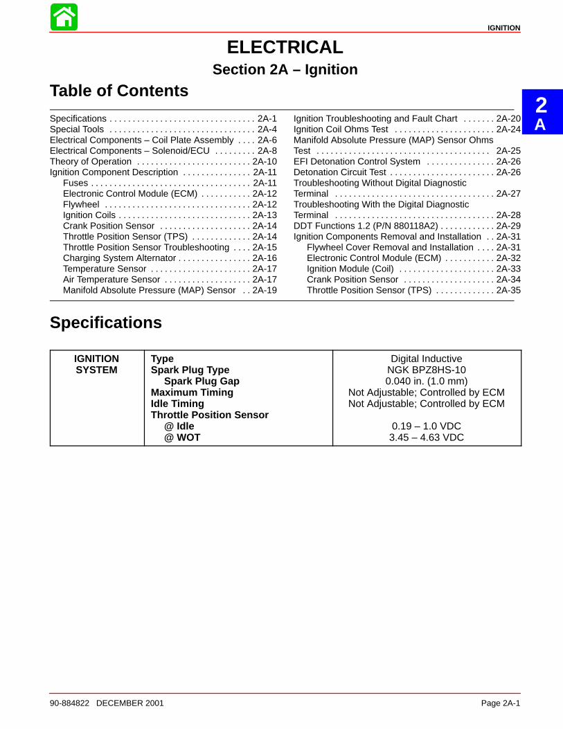
Specifications
IGNITIONSYSTEM
TypeSpark Plug Type
Spark Plug GapMaximum TimingIdle TimingThrottle Position Sensor
@ Idle@ WOT
Digital InductiveNGK BPZ8HS-100.040 in. (1.0 mm)
Not Adjustable; Controlled by ECMNot Adjustable; Controlled by ECM
0.19 – 1.0 VDC3.45 – 4.63 VDC
IGNITION
Page 2A-2 90-884822 DECEMBER 2001
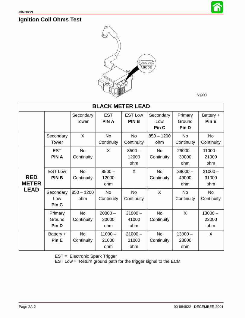
Ignition Coil Ohms Test
58903
BLACK METER LEAD
SecondaryTower
ESTPIN A
EST LowPIN B
SecondaryLow
Pin C
PrimaryGroundPin D
Battery +Pin E
SecondaryTower
X NoContinuity
NoContinuity
850 – 1200ohm
NoContinuity
NoContinuity
ESTPIN A
NoContinuity
X 8500 –12000ohm
NoContinuity
29000 –39000ohm
11000 –21000ohm
REDMETERLEAD
EST LowPIN B
NoContinuity
8500 –12000ohm
X NoContinuity
39000 –49000ohm
21000 –31000ohm
LEAD SecondaryLow
Pin C
850 – 1200ohm
NoContinuity
NoContinuity
X NoContinuity
NoContinuity
PrimaryGroundPin D
NoContinuity
20000 – 30000ohm
31000 –41000ohm
NoContinuity
X 13000 – 23000ohm
Battery +Pin E
NoContinuity
11000 –21000ohm
21000 –31000ohm
NoContinuity
13000 – 23000ohm
X
EST = Electronic Spark TriggerEST Low = Return ground path for the trigger signal to the ECM
IGNITION
90-884822 DECEMBER 2001 Page 2A-3
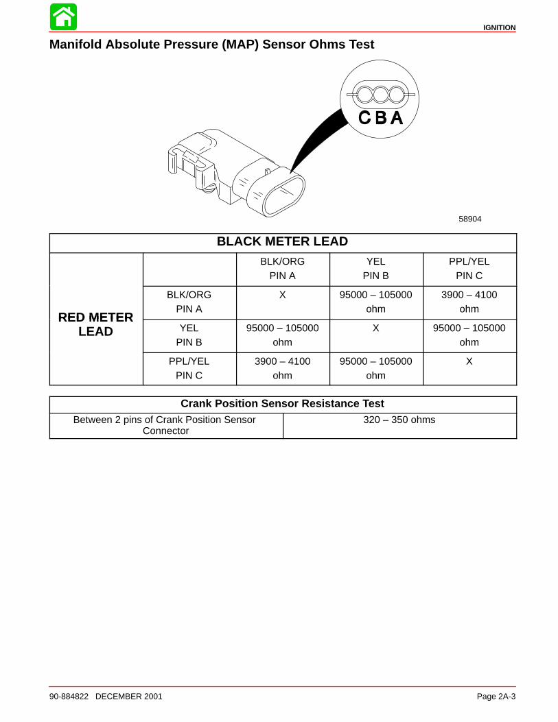
Manifold Absolute Pressure (MAP) Sensor Ohms Test
58904
BLACK METER LEAD
BLK/ORGPIN A
YELPIN B
PPL/YELPIN C
RED METER
BLK/ORGPIN A
X 95000 – 105000ohm
3900 – 4100ohm
RED METERLEAD YEL
PIN B95000 – 105000
ohmX 95000 – 105000
ohm
PPL/YELPIN C
3900 – 4100ohm
95000 – 105000ohm
X
Crank Position Sensor Resistance TestBetween 2 pins of Crank Position Sensor
Connector320 – 350 ohms
IGNITION
Page 2A-4 90-884822 DECEMBER 2001
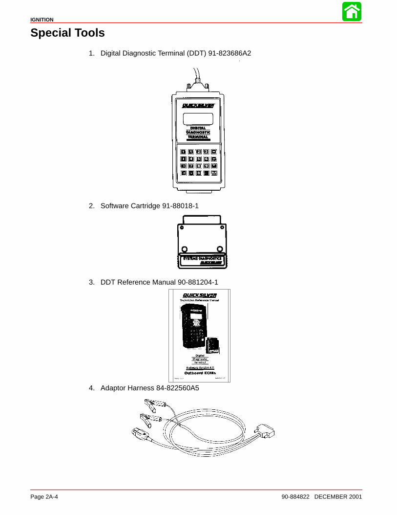
Special Tools
1. Digital Diagnostic Terminal (DDT) 91-823686A2
2. Software Cartridge 91-88018-1
3. DDT Reference Manual 90-881204-1
4. Adaptor Harness 84-822560A5
IGNITION
90-884822 DECEMBER 2001 Page 2A-5
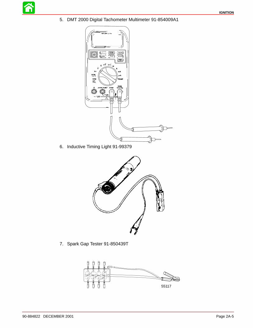
5. DMT 2000 Digital Tachometer Multimeter 91-854009A1
6. Inductive Timing Light 91-99379
7. Spark Gap Tester 91-850439T
55117
IGNITION
Page 2A-6 90-884822 DECEMBER 2001
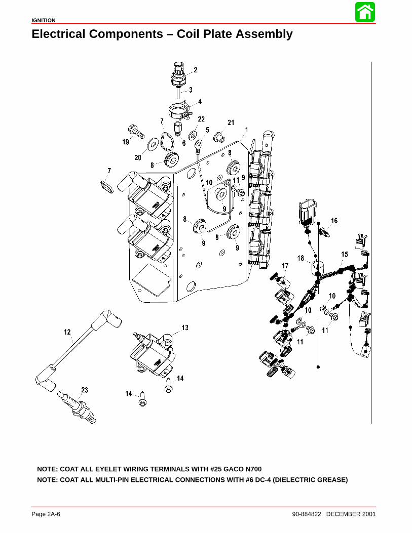
Electrical Components – Coil Plate Assembly
NOTE: COAT ALL EYELET WIRING TERMINALS WITH #25 GACO N700
NOTE: COAT ALL MULTI-PIN ELECTRICAL CONNECTIONS WITH #6 DC-4 (DIELECTRIC GREASE)
IGNITION
90-884822 DECEMBER 2001 Page 2A-7
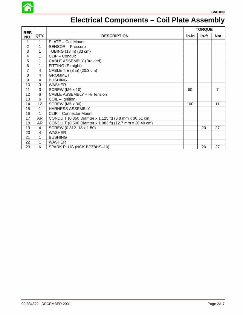
Electrical Components – Coil Plate Assembly
REFTORQUE
REF.NO. QTY. DESCRIPTION lb-in lb-ft Nm
1 1 PLATE – Coil Mount2 1 SENSOR – Pressure3 1 TUBING (13 in) (33 cm)4 1 CLIP – Conduit5 1 CABLE ASSEMBLY (Braided)6 1 FITTING (Straight)7 4 CABLE TIE (8 in) (20.3 cm)8 4 GROMMET9 4 BUSHING10 3 WASHER11 3 SCREW (M6 x 10) 60 712 6 CABLE ASSEMBLY – Hi Tension13 6 COIL – Ignition14 12 SCREW (M6 x 30) 100 1115 1 HARNESS ASSEMBLY16 1 CLIP – Connector Mount17 AR CONDUIT (0.350 Diamter x 1.125 ft) (8.8 mm x 30.51 cm)18 AR CONDUIT (0.500 Diamter x 1.083 ft) (12.7 mm x 30.49 cm)19 4 SCREW (0.312–18 x 1.50) 20 2720 4 WASHER21 1 BUSHING22 1 WASHER23 6 SPARK PLUG (NGK BPZ8HS–10) 20 27
IGNITION
Page 2A-8 90-884822 DECEMBER 2001
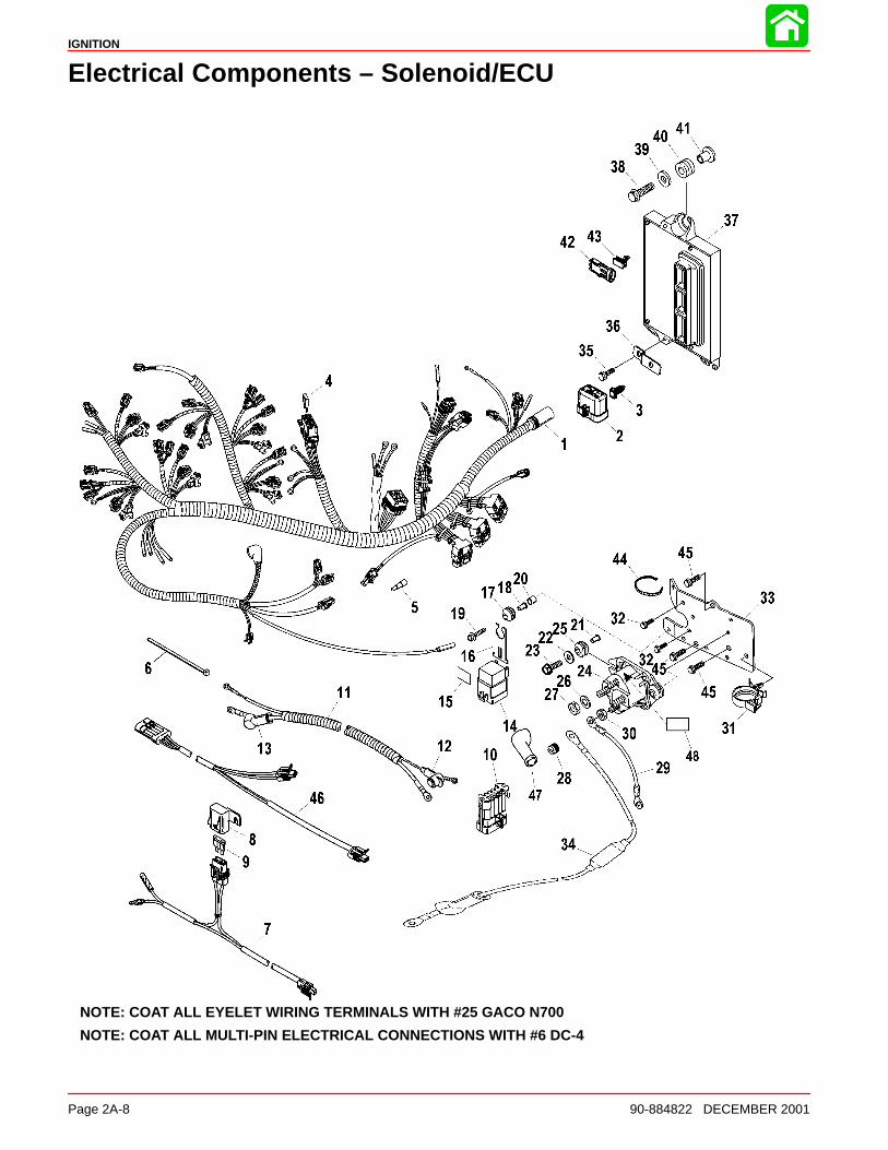
Electrical Components – Solenoid/ECU
NOTE: COAT ALL EYELET WIRING TERMINALS WITH #25 GACO N700
NOTE: COAT ALL MULTI-PIN ELECTRICAL CONNECTIONS WITH #6 DC-4
IGNITION
90-884822 DECEMBER 2001 Page 2A-9
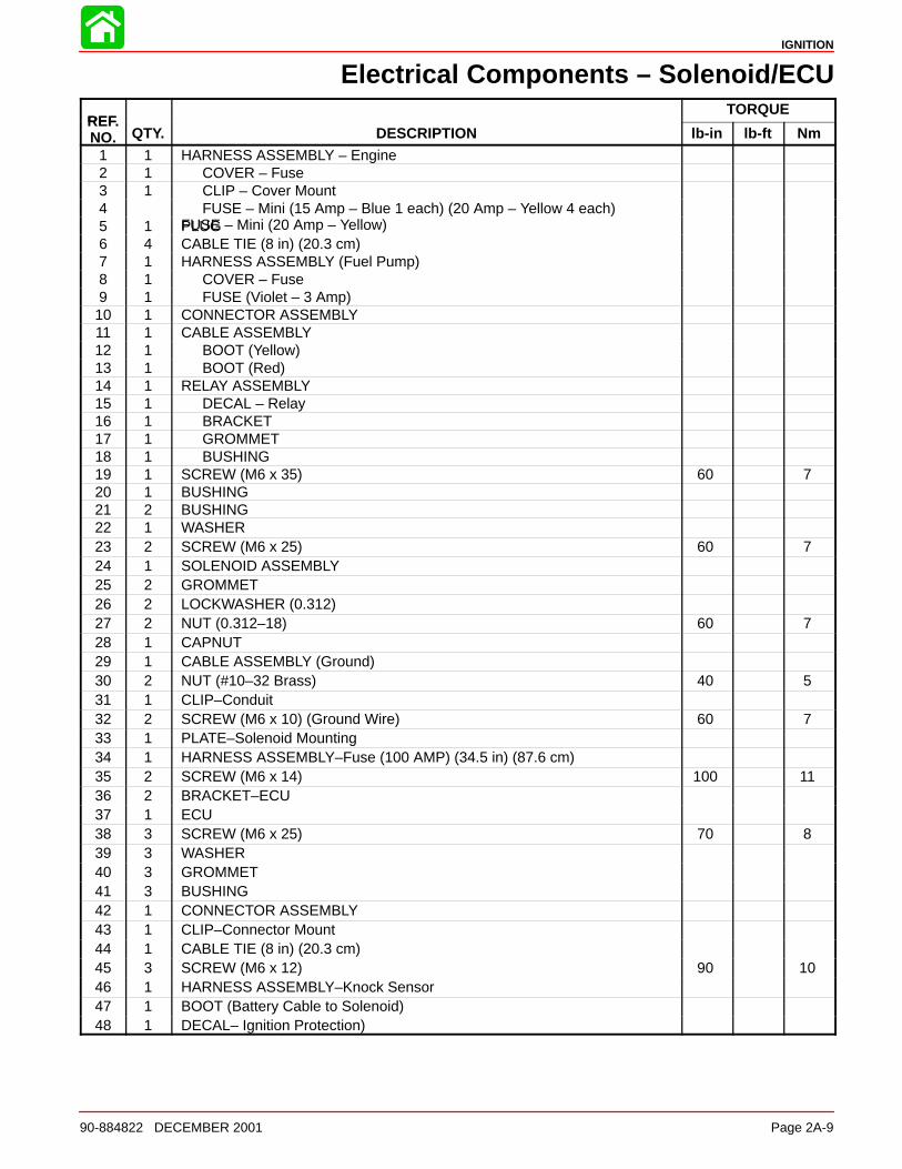
Electrical Components – Solenoid/ECU
REFTORQUE
REF.NO. QTY. DESCRIPTION lb-in lb-ft Nm
1 1 HARNESS ASSEMBLY – Engine2 1 COVER – Fuse3 1 CLIP – Cover Mount4 FUSE – Mini (15 Amp – Blue 1 each) (20 Amp – Yellow 4 each)
FUSE – Mini (20 Amp – Yellow)5 1 PLUG6 4 CABLE TIE (8 in) (20.3 cm)7 1 HARNESS ASSEMBLY (Fuel Pump)8 1 COVER – Fuse9 1 FUSE (Violet – 3 Amp)10 1 CONNECTOR ASSEMBLY11 1 CABLE ASSEMBLY12 1 BOOT (Yellow)13 1 BOOT (Red)14 1 RELAY ASSEMBLY15 1 DECAL – Relay16 1 BRACKET17 1 GROMMET18 1 BUSHING19 1 SCREW (M6 x 35) 60 720 1 BUSHING21 2 BUSHING22 1 WASHER23 2 SCREW (M6 x 25) 60 724 1 SOLENOID ASSEMBLY25 2 GROMMET26 2 LOCKWASHER (0.312)27 2 NUT (0.312–18) 60 728 1 CAPNUT29 1 CABLE ASSEMBLY (Ground)30 2 NUT (#10–32 Brass) 40 531 1 CLIP–Conduit32 2 SCREW (M6 x 10) (Ground Wire) 60 733 1 PLATE–Solenoid Mounting34 1 HARNESS ASSEMBLY–Fuse (100 AMP) (34.5 in) (87.6 cm)35 2 SCREW (M6 x 14) 100 1136 2 BRACKET–ECU37 1 ECU38 3 SCREW (M6 x 25) 70 839 3 WASHER40 3 GROMMET41 3 BUSHING42 1 CONNECTOR ASSEMBLY43 1 CLIP–Connector Mount44 1 CABLE TIE (8 in) (20.3 cm)45 3 SCREW (M6 x 12) 90 1046 1 HARNESS ASSEMBLY–Knock Sensor47 1 BOOT (Battery Cable to Solenoid)48 1 DECAL– Ignition Protection)
IGNITION
Page 2A-10 90-884822 DECEMBER 2001
Theory of Operation
When the ignition key switch is turned to the “RUN” position, battery voltage is applied toboth the Electronic Control Module (ECM) through the purple wire and the main powerrelay through the red/purple wire. As the ECM receives the “RUN” signal, it internally com-pletes the ground circuit of the main relay, for a short period of time, energizing the fuelpump for start-up. As the engine is cranked with the starter motor, the ECM receives therun signal from the Crank Position Sensor (CPS) and completes the ground circuit to themain relay for engine operation. With the main relay closed (completed circuit), D.C. cur-rent from the battery/charging system is transferred through the 20 ampere main relayfuse to the positive terminal of all ignition coil primary windings. The negative terminalsof the ignition coil primaries are connected to engine ground through the coils’ internaldriver, which is triggered by the ECM. With the coil drivers closed, a electric magnetic fieldis allowed to build up within the ignition coil. As the flywheel rotates, the CPS senses thelocation of the 54 teeth on the flywheel and supplies the trigger signal information to theECM. The ECM utilizes the CPS information and determines when to remove the triggersignal from the coil driver of each ignition coil. The coil driver then opens the coil primaryground circuit, allowing it’s magnetic field to rapidly collapse across the coil secondarywinding, which induces a high voltage charge (28,000 volts) that fires the spark plug.
IGNITION
90-884822 DECEMBER 2001 Page 2A-11
Ignition Component Description
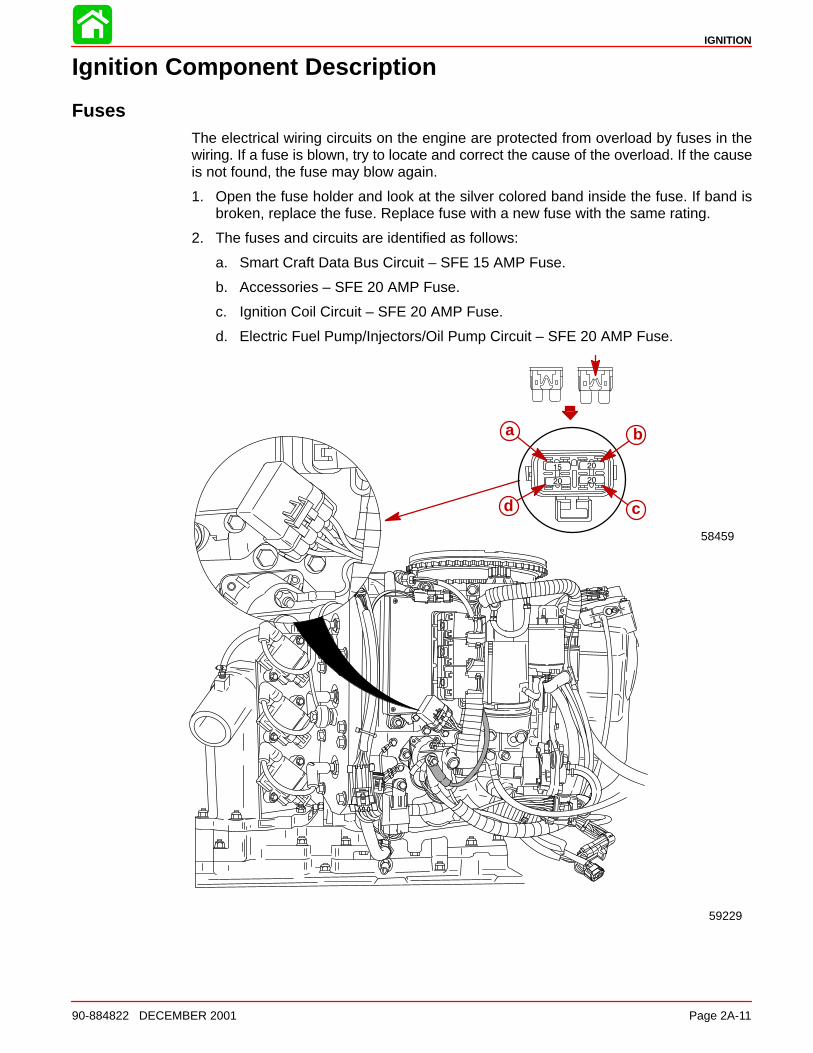
FusesThe electrical wiring circuits on the engine are protected from overload by fuses in thewiring. If a fuse is blown, try to locate and correct the cause of the overload. If the causeis not found, the fuse may blow again.
1. Open the fuse holder and look at the silver colored band inside the fuse. If band isbroken, replace the fuse. Replace fuse with a new fuse with the same rating.
2. The fuses and circuits are identified as follows:
a. Smart Craft Data Bus Circuit – SFE 15 AMP Fuse.
b. Accessories – SFE 20 AMP Fuse.
c. Ignition Coil Circuit – SFE 20 AMP Fuse.
d. Electric Fuel Pump/Injectors/Oil Pump Circuit – SFE 20 AMP Fuse.
a
58459
d c
b
59229
IGNITION
Page 2A-12 90-884822 DECEMBER 2001
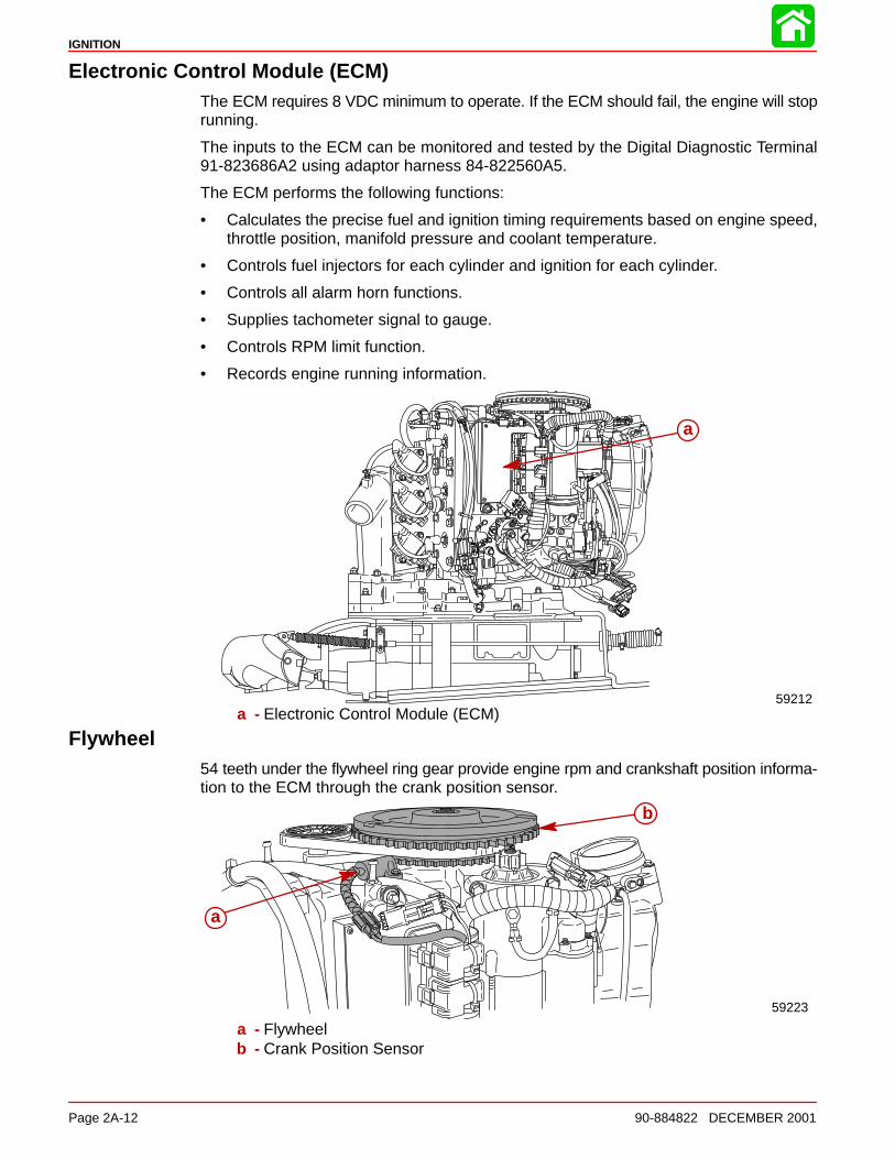
Electronic Control Module (ECM)The ECM requires 8 VDC minimum to operate. If the ECM should fail, the engine will stoprunning.
The inputs to the ECM can be monitored and tested by the Digital Diagnostic Terminal91-823686A2 using adaptor harness 84-822560A5.
The ECM performs the following functions:
• Calculates the precise fuel and ignition timing requirements based on engine speed,throttle position, manifold pressure and coolant temperature.
• Controls fuel injectors for each cylinder and ignition for each cylinder.
• Controls all alarm horn functions.
• Supplies tachometer signal to gauge.
• Controls RPM limit function.
• Records engine running information.
a
59212a - Electronic Control Module (ECM)
Flywheel54 teeth under the flywheel ring gear provide engine rpm and crankshaft position informa-tion to the ECM through the crank position sensor.
b
a
59223
a - Flywheelb - Crank Position Sensor
IGNITION
90-884822 DECEMBER 2001 Page 2A-13
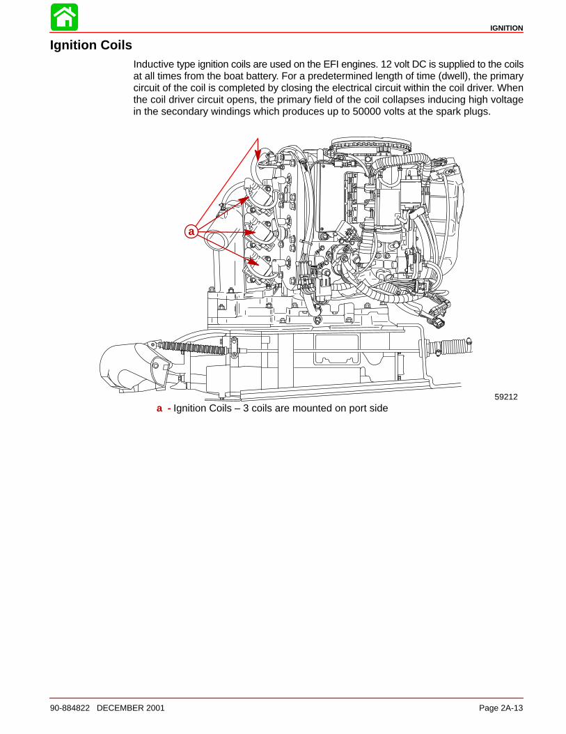
Ignition CoilsInductive type ignition coils are used on the EFI engines. 12 volt DC is supplied to the coilsat all times from the boat battery. For a predetermined length of time (dwell), the primarycircuit of the coil is completed by closing the electrical circuit within the coil driver. Whenthe coil driver circuit opens, the primary field of the coil collapses inducing high voltagein the secondary windings which produces up to 50000 volts at the spark plugs.
a
59212a - Ignition Coils – 3 coils are mounted on port side
IGNITION
Page 2A-14 90-884822 DECEMBER 2001
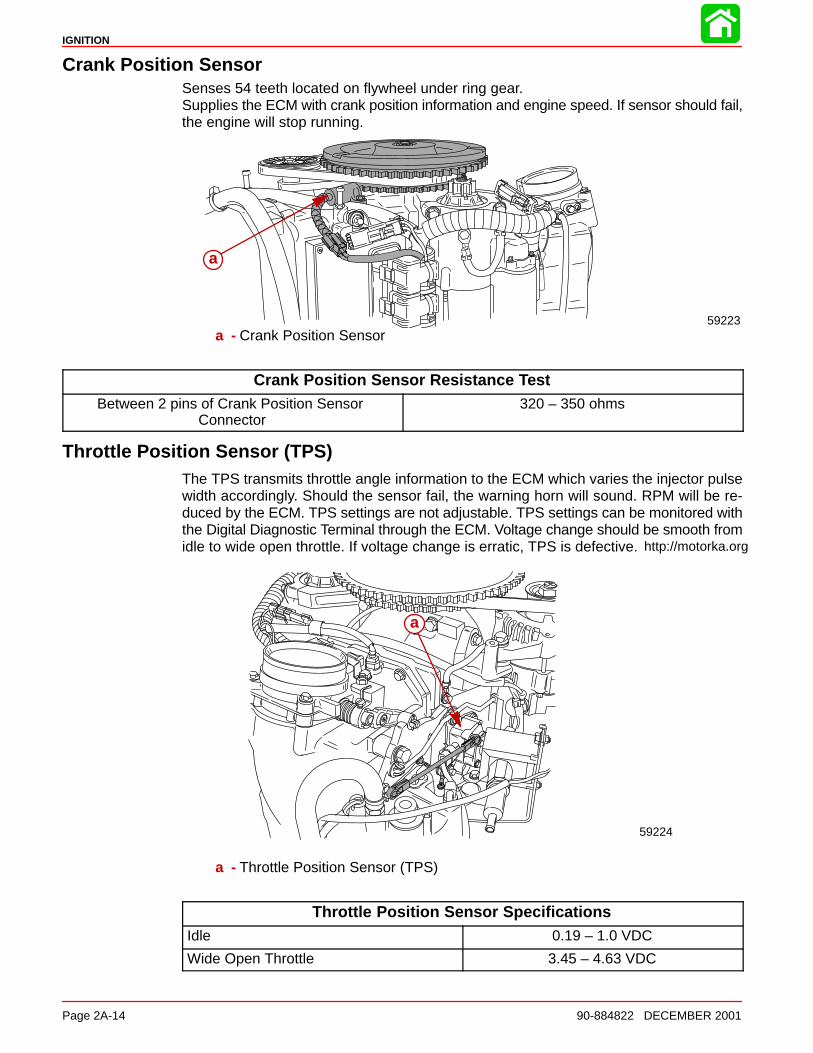
Crank Position SensorSenses 54 teeth located on flywheel under ring gear.Supplies the ECM with crank position information and engine speed. If sensor should fail,the engine will stop running.
a
59223a - Crank Position Sensor
Crank Position Sensor Resistance TestBetween 2 pins of Crank Position Sensor
Connector320 – 350 ohms
Throttle Position Sensor (TPS)The TPS transmits throttle angle information to the ECM which varies the injector pulsewidth accordingly. Should the sensor fail, the warning horn will sound. RPM will be re-duced by the ECM. TPS settings are not adjustable. TPS settings can be monitored withthe Digital Diagnostic Terminal through the ECM. Voltage change should be smooth fromidle to wide open throttle. If voltage change is erratic, TPS is defective.
59224
a
a - Throttle Position Sensor (TPS)
Throttle Position Sensor SpecificationsIdle 0.19 – 1.0 VDC
Wide Open Throttle 3.45 – 4.63 VDC
http://motorka.org

IGNITION
90-884822 DECEMBER 2001 Page 2A-15
Throttle Position Sensor (TPS) TroubleshootingIf the throttle position sensor is out of the intended operating range when the engine isstarted, the Electronic Control Module (ECM) will sense that the Throttle Position Sensor(TPS) has failed. The warning horn will sound, check engine light will illuminate, DDT willindicate failed TPS and the engine will go into RPM reduction. When the engine is started,the throttle arm on the engine must be against the throttle stop screw. Do not move throttleor fast idle control lever forward.
• Check throttle cable adjustment. The throttle stop screw on the throttle arm must beagainst the throttle stop on the cylinder block when the engine is started. Pre-load thethrottle cable barrel 1 or 2 turns if necessary.
• Verify driver is not pushing on throttle (if foot throttle is used) or advancing the throttleonly on the control box.
• Check throttle cam to roller adjustment. If the roller is not down in the pocket/valleyarea on the cam, there is a tendency for the roller to ride up or down on the cam whichcauses the TPS link arm to push/pull on the TPS lever resulting changing values.
IGNITION
Page 2A-16 90-884822 DECEMBER 2001
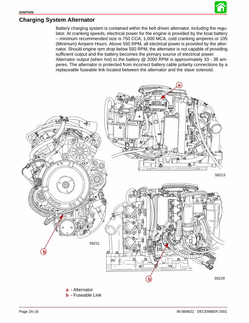
Charging System AlternatorBattery charging system is contained within the belt driven alternator, including the regu-lator. At cranking speeds, electrical power for the engine is provided by the boat battery– minimum recommended size is 750 CCA, 1,000 MCA, cold cranking amperes or 105(Minimum) Ampere Hours. Above 550 RPM, all electrical power is provided by the alter-nator. Should engine rpm drop below 550 RPM, the alternator is not capable of providingsufficient output and the battery becomes the primary source of electrical power. Alternator output (when hot) to the battery @ 2000 RPM is approximately 33 - 38 am-peres. The alternator is protected from incorrect battery cable polarity connections by areplaceable fuseable link located between the alternator and the slave solenoid.
59213
a
b
b
59211
59229
a - Alternatorb - Fuseable Link
IGNITION
90-884822 DECEMBER 2001 Page 2A-17
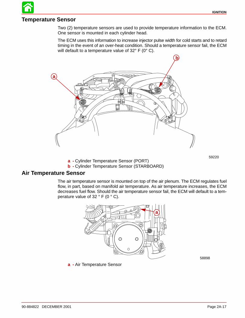
Temperature SensorTwo (2) temperature sensors are used to provide temperature information to the ECM.One sensor is mounted in each cylinder head.
The ECM uses this information to increase injector pulse width for cold starts and to retardtiming in the event of an over-heat condition. Should a temperature sensor fail, the ECMwill default to a temperature value of 32° F (0° C).
a
b
59220a - Cylinder Temperature Sensor (PORT)b - Cylinder Temperature Sensor (STARBOARD)
Air Temperature SensorThe air temperature sensor is mounted on top of the air plenum. The ECM regulates fuelflow, in part, based on manifold air temperature. As air temperature increases, the ECMdecreases fuel flow. Should the air temperature sensor fail, the ECM will default to a tem-perature value of 32 ° F (0 ° C).
58898
a
a - Air Temperature Sensor
IGNITION
Page 2A-18 90-884822 DECEMBER 2001
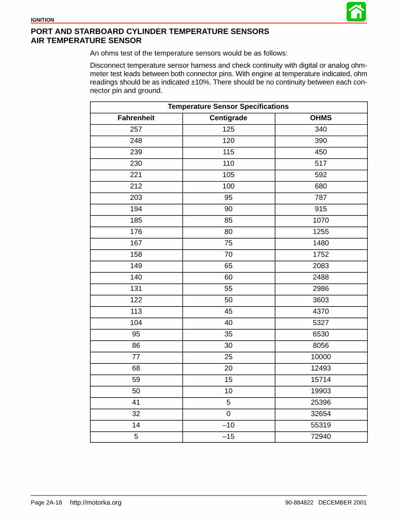
PORT AND STARBOARD CYLINDER TEMPERATURE SENSORSAIR TEMPERATURE SENSOR
An ohms test of the temperature sensors would be as follows:
Disconnect temperature sensor harness and check continuity with digital or analog ohm-meter test leads between both connector pins. With engine at temperature indicated, ohmreadings should be as indicated ±10%. There should be no continuity between each con-nector pin and ground.
Temperature Sensor Specifications
Fahrenheit Centigrade OHMS
257 125 340
248 120 390
239 115 450
230 110 517
221 105 592
212 100 680
203 95 787
194 90 915
185 85 1070
176 80 1255
167 75 1480
158 70 1752
149 65 2083
140 60 2488
131 55 2986
122 50 3603
113 45 4370
104 40 5327
95 35 6530
86 30 8056
77 25 10000
68 20 12493
59 15 15714
50 10 19903
41 5 25396
32 0 32654
14 –10 55319
5 –15 72940
http://motorka.org
IGNITION
90-884822 DECEMBER 2001 Page 2A-19
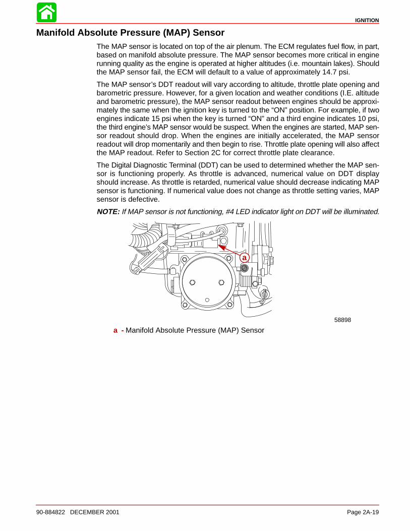
Manifold Absolute Pressure (MAP) SensorThe MAP sensor is located on top of the air plenum. The ECM regulates fuel flow, in part,based on manifold absolute pressure. The MAP sensor becomes more critical in enginerunning quality as the engine is operated at higher altitudes (i.e. mountain lakes). Shouldthe MAP sensor fail, the ECM will default to a value of approximately 14.7 psi.
The MAP sensor’s DDT readout will vary according to altitude, throttle plate opening andbarometric pressure. However, for a given location and weather conditions (I.E. altitudeand barometric pressure), the MAP sensor readout between engines should be approxi-mately the same when the ignition key is turned to the “ON” position. For example, if twoengines indicate 15 psi when the key is turned “ON” and a third engine indicates 10 psi,the third engine’s MAP sensor would be suspect. When the engines are started, MAP sen-sor readout should drop. When the engines are initially accelerated, the MAP sensorreadout will drop momentarily and then begin to rise. Throttle plate opening will also affectthe MAP readout. Refer to Section 2C for correct throttle plate clearance.
The Digital Diagnostic Terminal (DDT) can be used to determined whether the MAP sen-sor is functioning properly. As throttle is advanced, numerical value on DDT displayshould increase. As throttle is retarded, numerical value should decrease indicating MAPsensor is functioning. If numerical value does not change as throttle setting varies, MAPsensor is defective.
NOTE: If MAP sensor is not functioning, #4 LED indicator light on DDT will be illuminated.
a
58898
a - Manifold Absolute Pressure (MAP) Sensor
IGNITION
Page 2A-20 90-884822 DECEMBER 2001
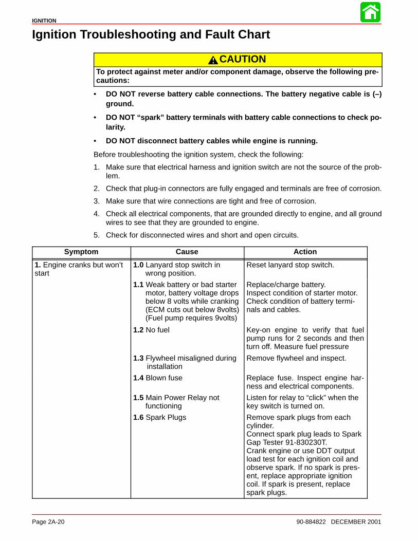
Ignition Troubleshooting and Fault Chart
CAUTIONTo protect against meter and/or component damage, observe the following pre-cautions:
• DO NOT reverse battery cable connections. The battery negative cable is (–)ground.
• DO NOT “spark” battery terminals with battery cable connections to check po-larity.
• DO NOT disconnect battery cables while engine is running.
Before troubleshooting the ignition system, check the following:
1. Make sure that electrical harness and ignition switch are not the source of the prob-lem.
2. Check that plug-in connectors are fully engaged and terminals are free of corrosion.
3. Make sure that wire connections are tight and free of corrosion.
4. Check all electrical components, that are grounded directly to engine, and all groundwires to see that they are grounded to engine.
5. Check for disconnected wires and short and open circuits.
Symptom Cause Action
1. Engine cranks but won’tstart
1.0 Lanyard stop switch in wrong position.
Reset lanyard stop switch.
1.1 Weak battery or bad starter motor, battery voltage dropsbelow 8 volts while cranking(ECM cuts out below 8volts)(Fuel pump requires 9volts)
Replace/charge battery.Inspect condition of starter motor.Check condition of battery termi-nals and cables.
1.2 No fuel Key-on engine to verify that fuelpump runs for 2 seconds and thenturn off. Measure fuel pressure
1.3 Flywheel misaligned during installation
Remove flywheel and inspect.
1.4 Blown fuse Replace fuse. Inspect engine har-ness and electrical components.
1.5 Main Power Relay notfunctioning
Listen for relay to “click” when thekey switch is turned on.
1.6 Spark Plugs Remove spark plugs from eachcylinder.Connect spark plug leads to SparkGap Tester 91-830230T.Crank engine or use DDT outputload test for each ignition coil andobserve spark. If no spark is pres-ent, replace appropriate ignitioncoil. If spark is present, replacespark plugs.
IGNITION
90-884822 DECEMBER 2001 Page 2A-21
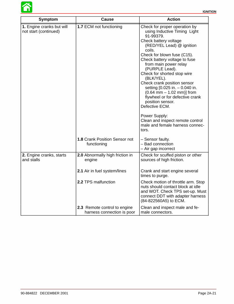
Symptom Cause Action
1. Engine cranks but willnot start (continued)
1.7 ECM not functioning
1.8 Crank Position Sensor not functioning
Check for proper operation byusing Inductive Timing Light91-99379.
Check battery voltage(RED/YEL Lead) @ ignitioncoils.
Check for blown fuse (C15).Check battery voltage to fuse
from main power relay(PURPLE Lead).
Check for shorted stop wire(BLK/YEL).
Check crank position sensorsetting [0.025 in. – 0.040 in. (0.64 mm – 1.02 mm)] fromflywheel or for defective crankposition sensor.
Defective ECM.
Power Supply:Clean and inspect remote controlmale and female harness connec-tors.
– Sensor faulty.– Bad connection– Air gap incorrect
2. Engine cranks, startsand stalls
2.0 Abnormally high friction inengine
Check for scuffed piston or othersources of high friction.
2.1 Air in fuel system/lines Crank and start engine severaltimes to purge.
2.2 TPS malfunction Check motion of throttle arm. Stopnuts should contact block at idleand WOT. Check TPS set-up. Mustconnect DDT with adapter harness(84-822560A5) to ECM.
2.3 Remote control to engineharness connection is poor
Clean and inspect male and fe-male connectors.
IGNITION
Page 2A-22 90-884822 DECEMBER 2001
Symptom Cause Action
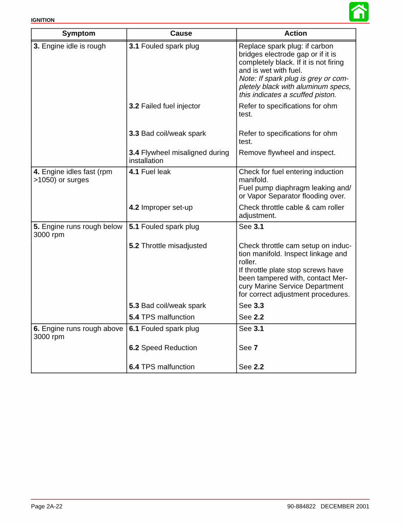
3. Engine idle is rough 3.1 Fouled spark plug Replace spark plug: if carbonbridges electrode gap or if it iscompletely black. If it is not firingand is wet with fuel.Note: If spark plug is grey or com-pletely black with aluminum specs,this indicates a scuffed piston.
3.2 Failed fuel injector Refer to specifications for ohmtest.
3.3 Bad coil/weak spark Refer to specifications for ohmtest.
3.4 Flywheel misaligned during installation
Remove flywheel and inspect.
4. Engine idles fast (rpm>1050) or surges
4.1 Fuel leak Check for fuel entering inductionmanifold.Fuel pump diaphragm leaking and/or Vapor Separator flooding over.
4.2 Improper set-up Check throttle cable & cam rolleradjustment.
5. Engine runs rough below3000 rpm
5.1 Fouled spark plug See 3.1
5.2 Throttle misadjusted Check throttle cam setup on induc-tion manifold. Inspect linkage androller.If throttle plate stop screws havebeen tampered with, contact Mer-cury Marine Service Departmentfor correct adjustment procedures.
5.3 Bad coil/weak spark See 3.3
5.4 TPS malfunction See 2.2
6. Engine runs rough above3000 rpm
6.1 Fouled spark plug See 3.1
6.2 Speed Reduction See 7
6.4 TPS malfunction See 2.2
IGNITION
90-884822 DECEMBER 2001 Page 2A-23
Symptom Cause Action
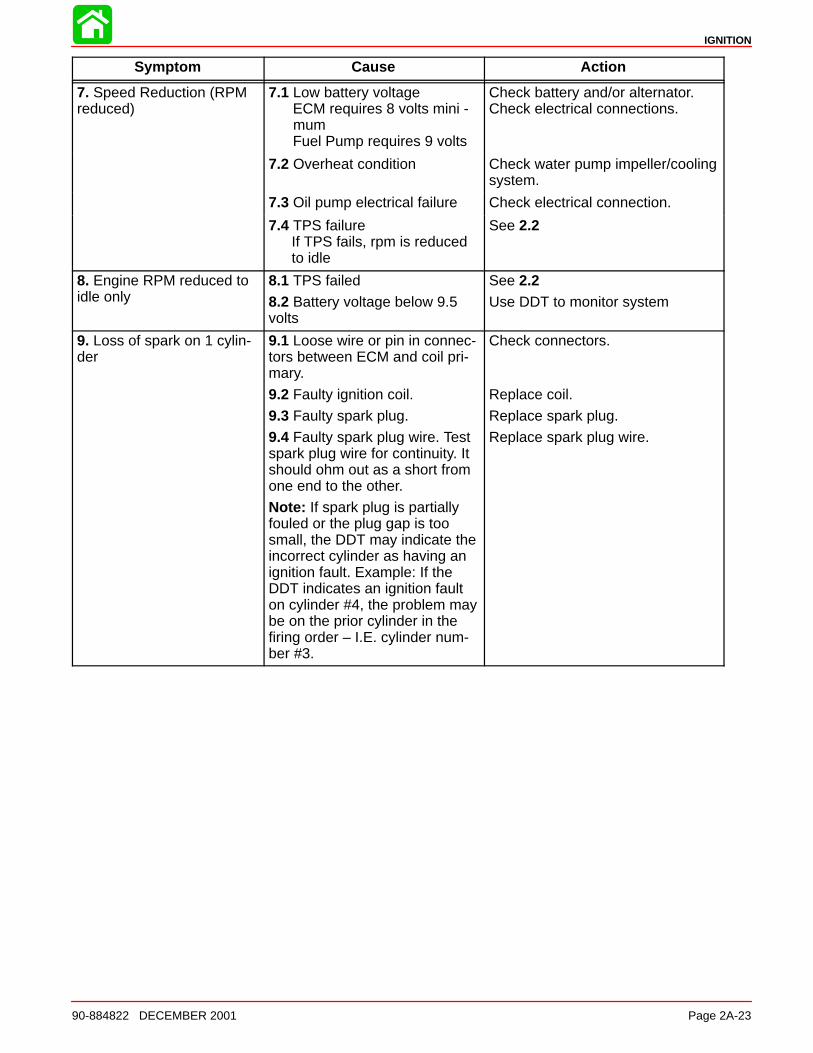
7. Speed Reduction (RPMreduced)
7.1 Low battery voltageECM requires 8 volts mini -
mumFuel Pump requires 9 volts
Check battery and/or alternator.Check electrical connections.
7.2 Overheat condition Check water pump impeller/coolingsystem.
7.3 Oil pump electrical failure Check electrical connection.
7.4 TPS failureIf TPS fails, rpm is reduced to idle
See 2.2
8. Engine RPM reduced toidle only
8.1 TPS failed
8.2 Battery voltage below 9.5volts
See 2.2Use DDT to monitor system
9. Loss of spark on 1 cylin-der
9.1 Loose wire or pin in connec-tors between ECM and coil pri-mary.
9.2 Faulty ignition coil.
9.3 Faulty spark plug.
9.4 Faulty spark plug wire. Testspark plug wire for continuity. Itshould ohm out as a short fromone end to the other.
Note: If spark plug is partiallyfouled or the plug gap is toosmall, the DDT may indicate theincorrect cylinder as having anignition fault. Example: If theDDT indicates an ignition faulton cylinder #4, the problem maybe on the prior cylinder in thefiring order – I.E. cylinder num-ber #3.
Check connectors.
Replace coil.
Replace spark plug.
Replace spark plug wire.
IGNITION
Page 2A-24 90-884822 DECEMBER 2001
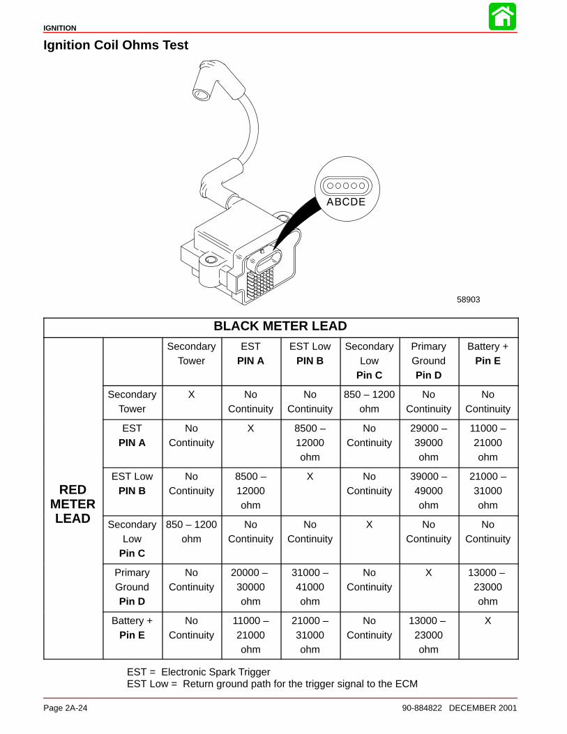
Ignition Coil Ohms Test
58903
BLACK METER LEAD
SecondaryTower
ESTPIN A
EST LowPIN B
SecondaryLow
Pin C
PrimaryGroundPin D
Battery +Pin E
SecondaryTower
X NoContinuity
NoContinuity
850 – 1200ohm
NoContinuity
NoContinuity
ESTPIN A
NoContinuity
X 8500 –12000ohm
NoContinuity
29000 –39000ohm
11000 –21000ohm
REDMETERLEAD
EST LowPIN B
NoContinuity
8500 –12000ohm
X NoContinuity
39000 –49000ohm
21000 –31000ohm
LEAD SecondaryLow
Pin C
850 – 1200ohm
NoContinuity
NoContinuity
X NoContinuity
NoContinuity
PrimaryGroundPin D
NoContinuity
20000 – 30000ohm
31000 –41000ohm
NoContinuity
X 13000 – 23000ohm
Battery +Pin E
NoContinuity
11000 –21000ohm
21000 –31000ohm
NoContinuity
13000 – 23000ohm
X
EST = Electronic Spark TriggerEST Low = Return ground path for the trigger signal to the ECM
IGNITION
90-884822 DECEMBER 2001 Page 2A-25
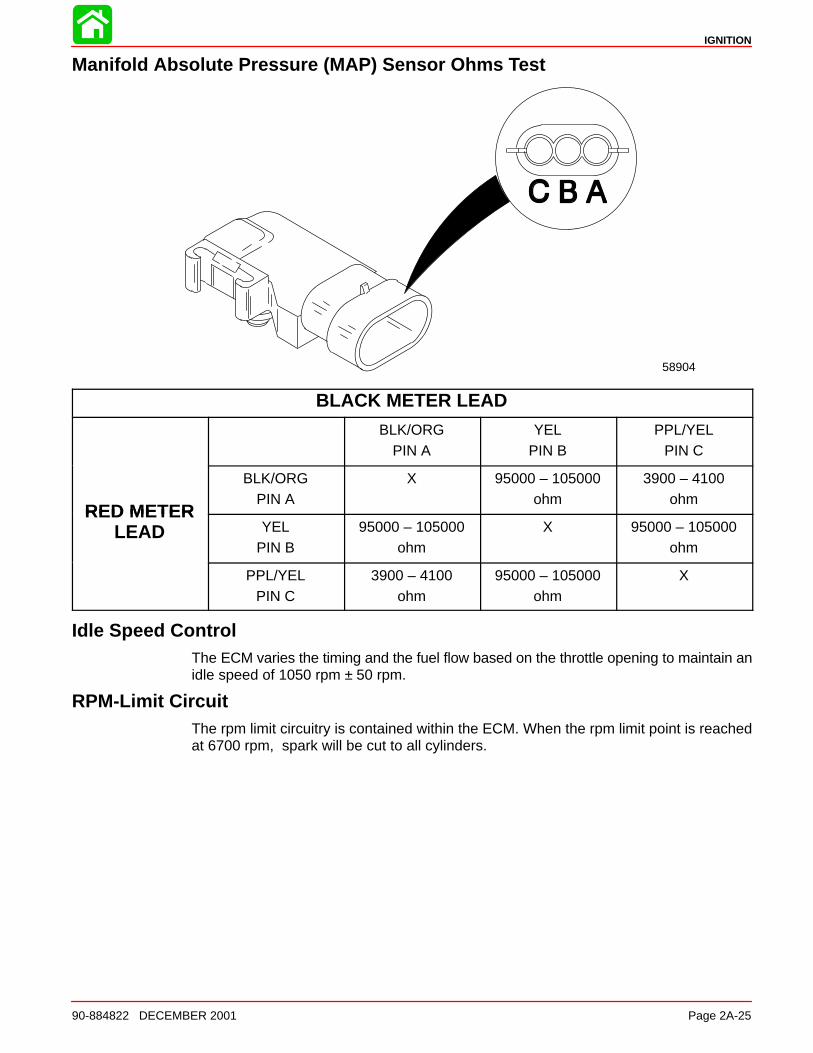
Manifold Absolute Pressure (MAP) Sensor Ohms Test
58904
BLACK METER LEAD
BLK/ORGPIN A
YELPIN B
PPL/YELPIN C
RED METER
BLK/ORGPIN A
X 95000 – 105000ohm
3900 – 4100ohm
RED METERLEAD YEL
PIN B95000 – 105000
ohmX 95000 – 105000
ohm
PPL/YELPIN C
3900 – 4100ohm
95000 – 105000ohm
X
Idle Speed ControlThe ECM varies the timing and the fuel flow based on the throttle opening to maintain anidle speed of 1050 rpm ± 50 rpm.
RPM-Limit CircuitThe rpm limit circuitry is contained within the ECM. When the rpm limit point is reachedat 6700 rpm, spark will be cut to all cylinders.
IGNITION
Page 2A-26 90-884822 DECEMBER 2001
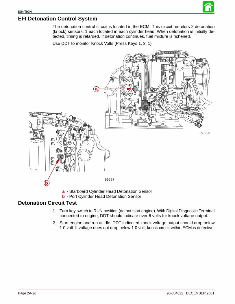
EFI Detonation Control SystemThe detonation control circuit is located in the ECM. This circuit monitors 2 detonation(knock) sensors; 1 each located in each cylinder head. When detonation is initially de-tected, timing is retarded. If detonation continues, fuel mixture is richened.
Use DDT to monitor Knock Volts (Press Keys 1, 3, 1)
59227
a
b
59228
a - Starboard Cylinder Head Detonation Sensorb - Port Cylinder Head Detonation Sensor
Detonation Circuit Test1. Turn key switch to RUN position (do not start engine). With Digital Diagnostic Terminal
connected to engine, DDT should indicate over 6 volts for knock voltage output.
2. Start engine and run at idle. DDT indicated knock voltage output should drop below1.0 volt. If voltage does not drop below 1.0 volt, knock circuit within ECM is defective.
IGNITION
90-884822 DECEMBER 2001 Page 2A-27
TroubleshootingThe ECM is designed such that if a sensor fails, the ECM will compensate so that the en-gine does not go into an over-rich condition.
Disconnecting a sensor for troubleshooting purposes may have no noticeable effect.
Troubleshooting Without Digital Diagnostic Terminal
Troubleshooting without the DDT is limited to checking resistance on some of the sen-sors.
Typical failures usually do not involve the ECM. Connectors, set-up, and mechanical wearare most likely at fault.
• Verify spark plug wires are securely installed (pushed in) into the coil tower.
• The engine may not run or may not run above idle with the wrong spark plugs installed.
• Swap ignition coils to see if the problem follows the coil or stays with the particularcylinder.
NOTE: ECMs are capable of performing a cylinder misfire test to isolate problem cylin-ders. Once a suspect cylinder is located, an output load test on the ignition coil and fuelinjector may be initiated through use of the DDT.
• Any sensor or connection can be disconnected and reconnected while the engine isoperating without damaging the ECM. Disconnecting the crank position sensor willstop the engine.
IMPORTANT: Any sensor that is disconnected while the engine is running will berecorded as a Fault in the ECM Fault History. Use the DDT to view and clear the faulthistory when troubleshooting/repair is completed.
• If all cylinders exhibit similar symptoms, the problem is with a sensor or harness inputto the ECM.
• If problem is speed related or intermittent, it is probably connector or contact related.Inspect connectors for corrosion, loose wires or loose pins. Secure connector seating;use dielectric compound 92-823506-1.
• Inspect the harness for obvious damage: pinched wires, chaffing.
• Secure grounds and all connections involving ring terminals (coat with Liquid Neo-prene).
• Check fuel pump connections and fuel pump pressure.
IGNITION
Page 2A-28 90-884822 DECEMBER 2001
Troubleshooting with the Digital Diagnostic Terminal
a
bdc
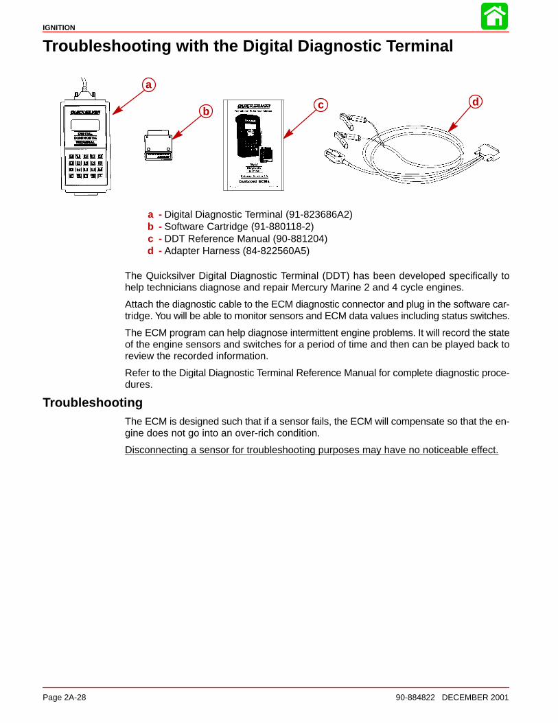
a - Digital Diagnostic Terminal (91-823686A2)b - Software Cartridge (91-880118-2)c - DDT Reference Manual (90-881204)d - Adapter Harness (84-822560A5)
The Quicksilver Digital Diagnostic Terminal (DDT) has been developed specifically tohelp technicians diagnose and repair Mercury Marine 2 and 4 cycle engines.
Attach the diagnostic cable to the ECM diagnostic connector and plug in the software car-tridge. You will be able to monitor sensors and ECM data values including status switches.
The ECM program can help diagnose intermittent engine problems. It will record the stateof the engine sensors and switches for a period of time and then can be played back toreview the recorded information.
Refer to the Digital Diagnostic Terminal Reference Manual for complete diagnostic proce-dures.
TroubleshootingThe ECM is designed such that if a sensor fails, the ECM will compensate so that the en-gine does not go into an over-rich condition.
Disconnecting a sensor for troubleshooting purposes may have no noticeable effect.
IGNITION
90-884822 DECEMBER 2001 Page 2A-29
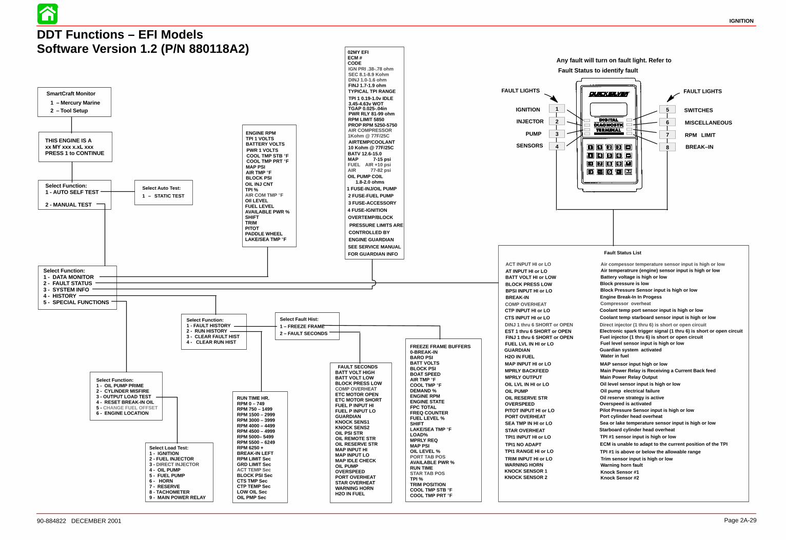
DDT Functions – EFI ModelsSoftware Version 1.2 (P/N 880118A2)
IGNITION
INJECTOR
PUMP
SENSORS
SWITCHES
MISCELLANEOUS
RPM LIMIT
BREAK–IN
SmartCraft Monitor
1 – Mercury Marine2 – Tool Setup
Select Auto Test:
1 – STATIC TEST
Select Fault Hist:
1 – FREEZE FRAME2 – FAULT SECONDS
1
2
3
4
5
6
7
8
FAULT LIGHTSFAULT LIGHTS
Any fault will turn on fault light. Refer to
Fault Status to identify fault
ACT INPUT HI or LOAT INPUT HI or LOBATT VOLT HI or LOWBLOCK PRESS LOWBPSI INPUT HI or LOBREAK-INCOMP OVERHEATCTP INPUT HI or LO
CTS INPUT HI or LODINJ 1 thru 6 SHORT or OPENEST 1 thru 6 SHORT or OPENFINJ 1 thru 6 SHORT or OPENFUEL LVL IN HI or LOGUARDIANH2O IN FUEL
MAP INPUT HI or LO
MPRLY OUTPUTOIL LVL IN HI or LOOIL PUMPOIL RESERVE STROVERSPEEDPITOT INPUT HI or LOPORT OVERHEATSEA TMP IN HI or LO
STAR OVERHEAT
TPI1 RANGE HI or LO
TRIM INPUT HI or LOWARNING HORN
Air compessor temperature sensor input is high or lowAir temperatrure (engine) sensor input is high or lowBattery voltage is high or lowBlock pressure is lowBlock Pressure Sensor input is high or low
Compressor overheatCoolant temp port sensor input is high or low
Coolant temp starboard sensor input is high or low
Direct injector (1 thru 6) is short or open circuitElectronic spark trigger signal (1 thru 6) is short or open circuitFuel injector (1 thru 6) is short or open circuitFuel level sensor input is high or lowGuardian system activatedWater in fuel
MAP sensor input high or low
Oil level sensor input is high or lowOil pump electrical failureOil reserve strategy is activeOverspeed is activatedPilot Pressure Sensor input is high or lowPort cylinder head overheatSea or lake temperature sensor input is high or lowStarboard cylinder head overheat
TPI #1 is above or below the allowable rangeTrim sensor input is high or lowWarning horn fault
MPRLY BACKFEED
TPI1 INPUT HI or LO TPI #1 sensor input is high or low
TPI1 NO ADAPT ECM is unable to adapt to the current position of the TPI
02MY EFI ECM # CODEIGN PRI .38-.78 ohmSEC 8.1-8.9 KohmDINJ 1.0-1.6 ohmFINJ 1.7-1.9 ohmTYPICAL TPI RANGE
TGAP 0.025-.04in
1 FUSE-INJ/OIL PUMP
AIR COMPRESSOR1Kohm @ 77F/25CAIRTEMP/COOLANT10 Kohm @ 77F/25C
RPM LIMIT 5850PROP RPM 5250-5750
2 FUSE-FUEL PUMP
3 FUSE-ACCESSORY
4 FUSE-IGNITION
OIL PUMP COIL1.8-2.0 ohms
OVERTEMP/BLOCK
PRESSURE LIMITS ARE
CONTROLLED BY
ENGINE GUARDIAN
SEE SERVICE MANUAL
FOR GUARDIAN INFO
ENGINE RPMTPI 1 VOLTSBATTERY VOLTSPWR 1 VOLTSCOOL TMP STB °FCOOL TMP PRT °FMAP PSIAIR TMP °FBLOCK PSIOIL INJ CNTTPI %AIR COM TMP °FOIl LEVELFUEL LEVELAVAILABLE PWR %SHIFTTRIMPITOTPADDLE WHEELLAKE/SEA TMP °F
RUN TIME HR.RPM 0 – 749RPM 750 – 1499RPM 1500 – 2999RPM 3000 – 3999RPM 4000 – 4499RPM 4500 – 4999RPM 5000– 5499RPM 5500 – 6249RPM 6250 +BREAK-IN LEFTRPM LIMIT SecGRD LIMIT SecACT TEMP SecBLOCK PSI SecCTS TMP SecCTP TEMP SecLOW OIL SecOIL PMP Sec
Engine Break-In In Progess
Main Power Relay is Receiving a Current Back feedMain Power Relay Output
Fault Status List
Select Load Test:1 - IGNITION2 - FUEL INJECTOR3 - DIRECT INJECTOR4 - OIL PUMP5 - FUEL PUMP6 - HORN7 - RESERVE8 - TACHOMETER9 - MAIN POWER RELAY
Select Function:1 - OIL PUMP PRIME2 - CYLINDER MISFIRE3 - OUTPUT LOAD TEST4 - RESET BREAK-IN OIL5 - CHANGE FUEL OFFSET6 - ENGINE LOCATION
THIS ENGINE IS Axx MY xxx x.xL xxxPRESS 1 to CONTINUE
Select Function:1 - DATA MONITOR2 - FAULT STATUS3 - SYSTEM INFO4 - HISTORY5 - SPECIAL FUNCTIONS
Select Function:1 - FAULT HISTORY2 - RUN HISTORY3 - CLEAR FAULT HIST4 - CLEAR RUN HIST
FREEZE FRAME BUFFERS0-BREAK-INBARO PSIBATT VOLTSBLOCK PSIBOAT SPEEDAIR TMP °FCOOL TMP °FDEMAND %ENGINE RPMENGINE STATEFPC TOTALFREQ COUNTERFUEL LEVEL %SHIFTLAKE/SEA TMP °FLOAD%MPRLY REQMAP PSIOIL LEVEL %PORT TAB POSAVAILABLE PWR %RUN TIMESTAR TAB POSTPI %TRIM POSITIONCOOL TMP STB °FCOOL TMP PRT °F
FAULT SECONDSBATT VOLT HIGHBATT VOLT LOWBLOCK PRESS LOWCOMP OVERHEATETC MOTOR OPENETC MOTOR SHORTFUEL P INPUT HIFUEL P INPUT LOGUARDIANKNOCK SENS1KNOCK SENS2OIL PSI STROIL REMOTE STROIL RESERVE STRMAP INPUT HIMAP INPUT LOMAP IDLE CHECKOIL PUMPOVERSPEEDPORT OVERHEATSTAR OVERHEATWARNING HORNH2O IN FUEL
Select Function:1 - AUTO SELF TEST
2 - MANUAL TEST
BATV 12.6-15.0MAP 7-15 psiFUEL AIR +10 psiAIR 77-82 psi
PWR RLY 81-99 ohm
TPI 1 0.19-1.0v IDLE3.45-4.63v WOT
KNOCK SENSOR 1KNOCK SENSOR 2
Knock Sensor #1Knock Sensor #2
IGNITION
90-884822 DECEMBER 2001 Page 2A-31
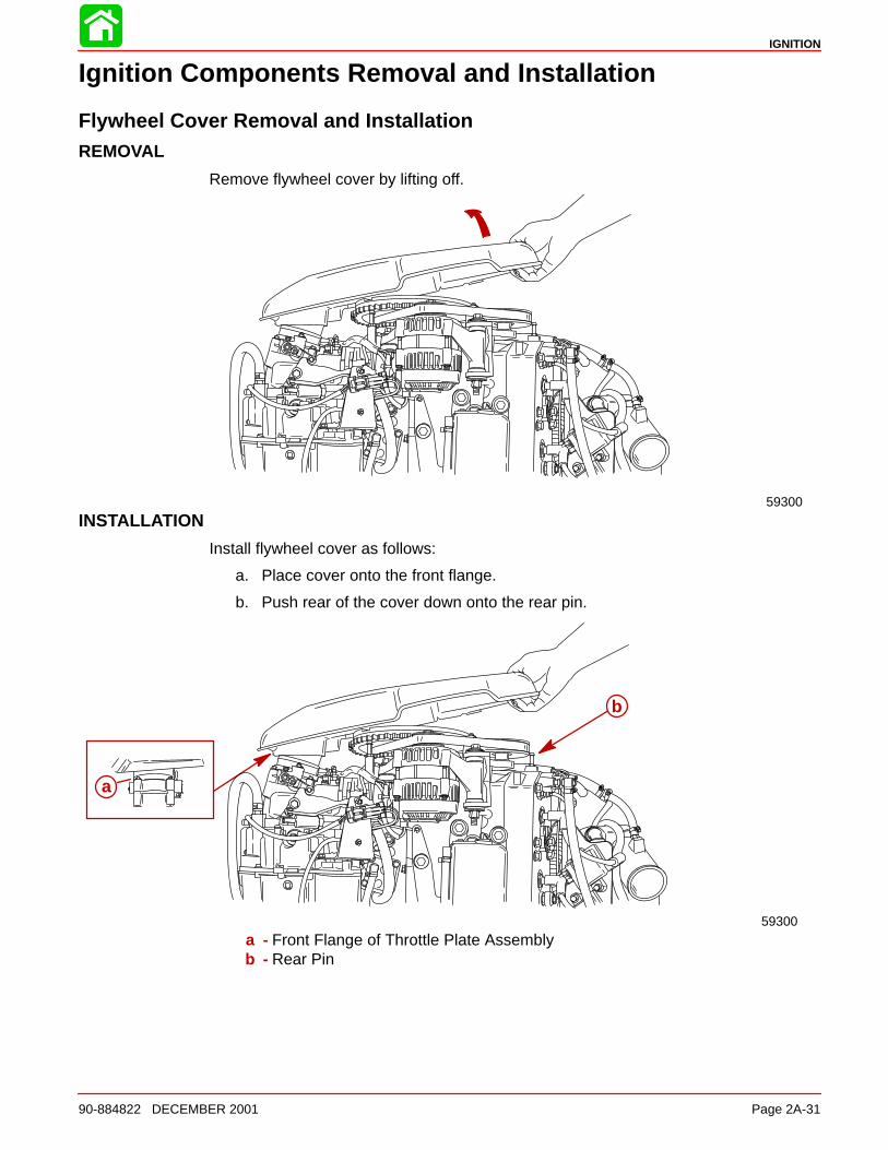
Ignition Components Removal and Installation
Flywheel Cover Removal and InstallationREMOVAL
Remove flywheel cover by lifting off.
59300
INSTALLATION
Install flywheel cover as follows:
a. Place cover onto the front flange.
b. Push rear of the cover down onto the rear pin.
a
59300
b
a - Front Flange of Throttle Plate Assemblyb - Rear Pin
IGNITION
90-884822 DECEMBER 2001Page 2A-32
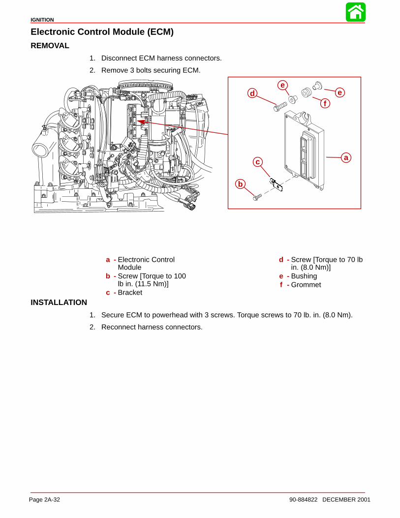
Electronic Control Module (ECM)REMOVAL
1. Disconnect ECM harness connectors.
2. Remove 3 bolts securing ECM.
a
b
f
c
de
e
a - Electronic ControlModule
b - Screw [Torque to 100lb in. (11.5 Nm)]
c - Bracket
d - Screw [Torque to 70 lbin. (8.0 Nm)]
e - Bushingf - Grommet
INSTALLATION
1. Secure ECM to powerhead with 3 screws. Torque screws to 70 lb. in. (8.0 Nm).
2. Reconnect harness connectors.
IGNITION
90-884822 DECEMBER 2001 Page 2A-33
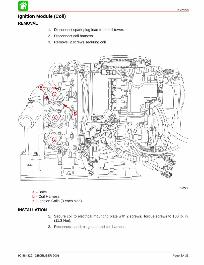
Ignition Module (Coil)REMOVAL
1. Disconnect spark plug lead from coil tower.
2. Disconnect coil harness.
3. Remove 2 screws securing coil.
a
b
c
c
c
59229a - Boltsb - Coil Harnessc - Ignition Coils (3 each side)
INSTALLATION
1. Secure coil to electrical mounting plate with 2 screws. Torque screws to 100 lb. in.(11.3 Nm).
2. Reconnect spark plug lead and coil harness.
IGNITION
90-884822 DECEMBER 2001Page 2A-34
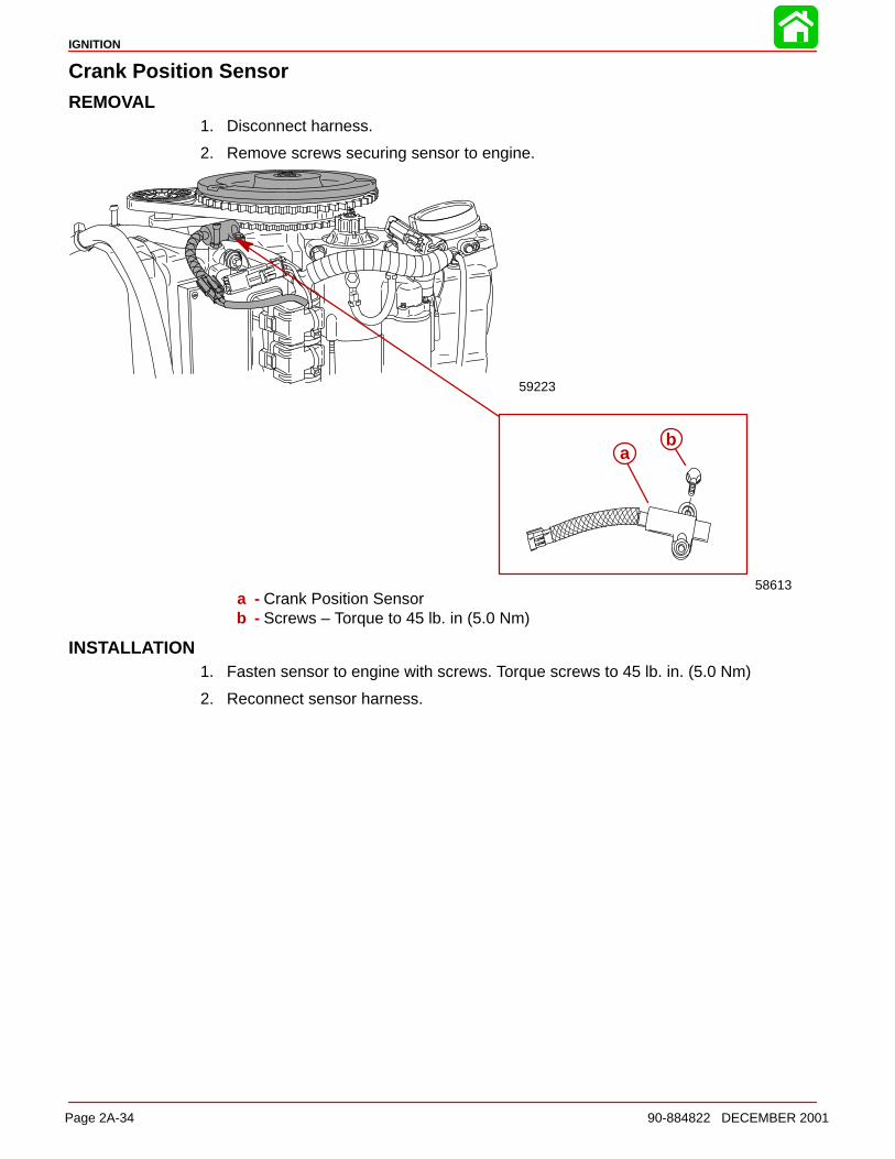
Crank Position SensorREMOVAL
1. Disconnect harness.
2. Remove screws securing sensor to engine.
58613
ab
59223
a - Crank Position Sensorb - Screws – Torque to 45 lb. in (5.0 Nm)
INSTALLATION1. Fasten sensor to engine with screws. Torque screws to 45 lb. in. (5.0 Nm)
2. Reconnect sensor harness.
IGNITION
90-884822 DECEMBER 2001 Page 2A-35
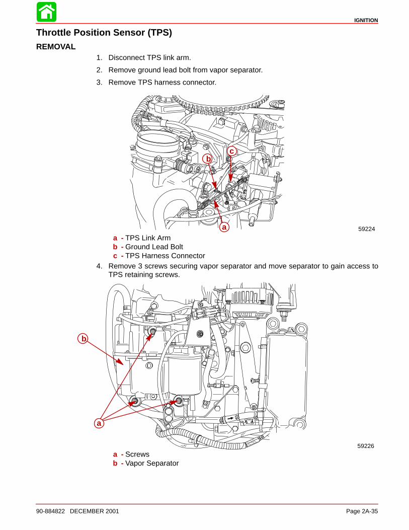
Throttle Position Sensor (TPS)REMOVAL
1. Disconnect TPS link arm.
2. Remove ground lead bolt from vapor separator.
3. Remove TPS harness connector.
59224a
bc
a - TPS Link Armb - Ground Lead Boltc - TPS Harness Connector
4. Remove 3 screws securing vapor separator and move separator to gain access toTPS retaining screws.
a
b
59226
a - Screwsb - Vapor Separator
IGNITION
90-884822 DECEMBER 2001Page 2A-36
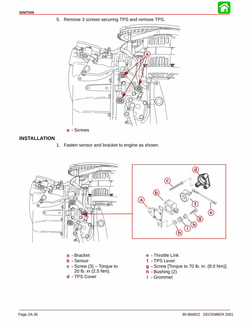
5. Remove 3 screws securing TPS and remove TPS.
a
a - Screws
INSTALLATION1. Fasten sensor and bracket to engine as shown.
ab
c
d
e
f
gh
ih
a - Bracketb - Sensorc - Screw (3) – Torque to
20 lb. in (2.5 Nm).d - TPS Cover
e - Throttle Linkf - TPS Leverg - Screw [Torque to 70 lb. in. (8.0 Nm)]h - Bushing (2)i - Grommet
IGNITION
90-884822 DECEMBER 2001 Page 2A-37
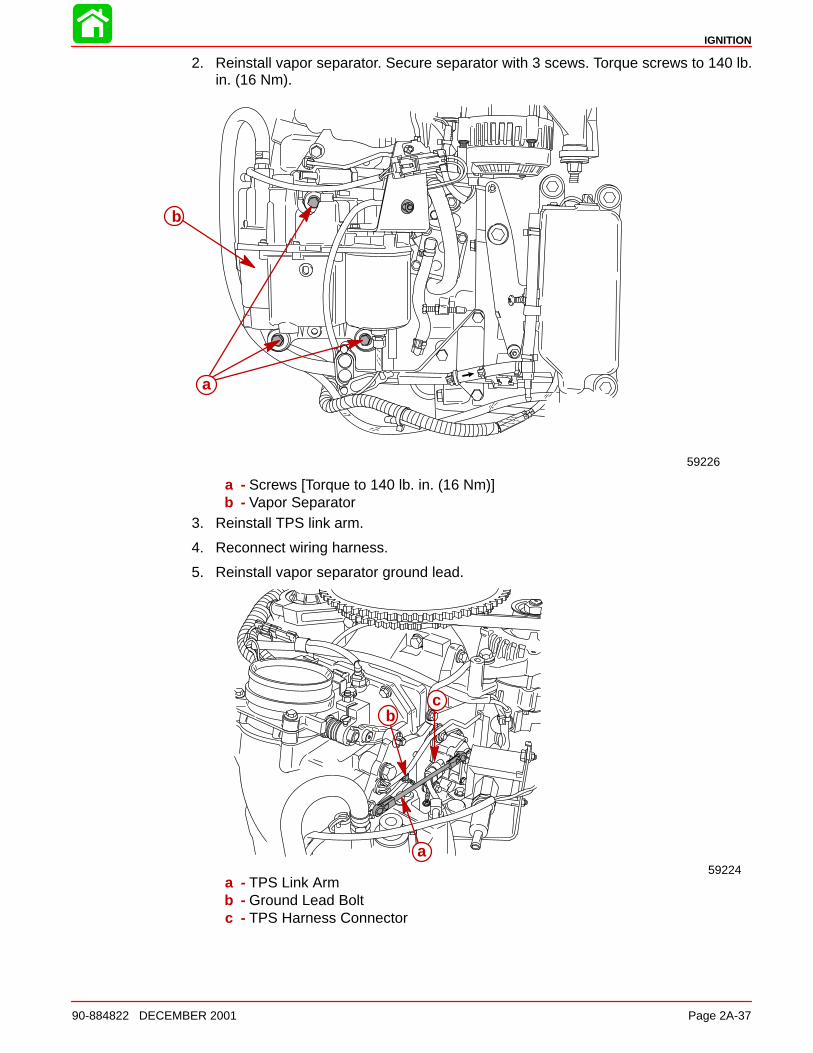
2. Reinstall vapor separator. Secure separator with 3 scews. Torque screws to 140 lb.in. (16 Nm).
a
b
59226
a - Screws [Torque to 140 lb. in. (16 Nm)]b - Vapor Separator
3. Reinstall TPS link arm.
4. Reconnect wiring harness.
5. Reinstall vapor separator ground lead.
59224
a
bc
a - TPS Link Armb - Ground Lead Boltc - TPS Harness Connector


![2a Dasar Lagrand Ok 2a [Compatibility Mode]](https://img.pdfslide.net/doc/110x75/563dbb2b550346aa9aaad652/2a-dasar-lagrand-ok-2a-compatibility-mode.jpg)