Embed Size (px)
Citation preview
1
Electrical Signature Analysis
Howard W Penrose, Ph.D.T-Solutions, Inc.
Welcome to a brief presentation on Electrical Signature Analysis.
My name is Dr Howard Penrose and I will be your narrator.
T-Solutions is a maintenance and reliability management consulting firm based in Chesapeake Virginia. Our primary clients include the US Navy and US Coast Guard.
This presentation is part 1 of 2
2
Flowchart For Problem Resolution
Don’t Mess With It!
YES NO
YES
YOU IDIOT!
NO
Will it Blow UpIn Your Hands?
NO
Look The Other Way
Anyone ElseKnows? You’re SCREWED!
YESYES
NO
Hide ItCan You Blame Someone Else?
NO
NO PROBLEM!
Yes
Is It Working?
Did You Mess With It?
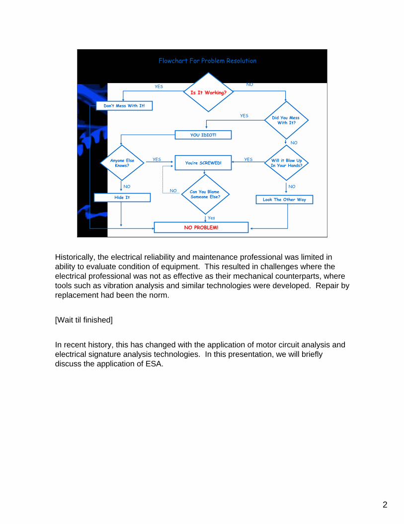
Historically, the electrical reliability and maintenance professional was limited in ability to evaluate condition of equipment. This resulted in challenges where the electrical professional was not as effective as their mechanical counterparts, where tools such as vibration analysis and similar technologies were developed. Repair by replacement had been the norm.
[Wait til finished]
In recent history, this has changed with the application of motor circuit analysis and electrical signature analysis technologies. In this presentation, we will briefly discuss the application of ESA.

3
This is a cutaway of a three-phase induction motor.The fan is used to cool the motor.Bearings and end shields hold the rotor centered in the motorStator laminations are designed to expel heat from the motor and reduce lossesStator windings are designed to be 120 degrees out of phase from each other and should be balanced.Rotor windings are a series of bars that are shorted at each end of the rotor and have current induced into them during motor operation.Between the stator and rotor windings is an air gap that must be maintained evenly about the stator. Uneven air gaps will cause low level vibration and will cause bearings to fail early.
The Polyphase Induction Motor
StatorWindings
Stator Laminations
RotorBearing
Fan

4
A motor uses the magnetic properties of attraction and repulsion to turn a shaft.In this simple diagram, wound coils around the stators create polarity.As the current changes direction, polarity changes, causing the rotor to be continually attracted and repulsed as it moves.Changes to impedance, inductance, and phase angle will effect the operation of the motor: its reliability, efficiency, and ability to develop torque.
In effect, an electric motor is an energy converter, converting electrical energy to mechanical torque.
Interaction of Rotor Field and Stator Field
Interaction of Two Magnetic Fields
Stator FieldRotor Field
N
S
NS
Electrical Energyto
Mechanical Torque
5
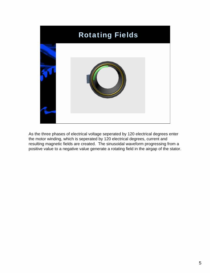
Rotating Fields
As the three phases of electrical voltage seperated by 120 electrical degrees enter the motor winding, which is seperated by 120 electrical degrees, current and resulting magnetic fields are created. The sinusoidal waveform progressing from a positive value to a negative value generate a rotating field in the airgap of the stator.

6
Rotating Field and Rotor Cage
The rotating fields cut through the conductors, or rotor bars, of the rotor. The result is current flow and a second magnetic field. The motor acts, quite literally, as a transformer with a rotating secondary with the stator as the primary and rotor as the secondary.
The current flow in the rotor, with it at a standstill, is the same frequency as the supply voltage. For example, a 60 hertz supply provides a 60 Hz field in the rotor. This generates a very high current, which is reflected through the stator windings as the four to eight times running current seen at the motor leads.
7
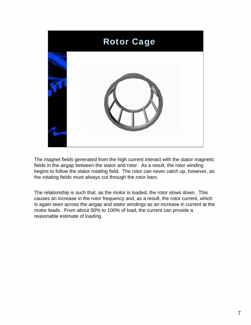
Rotor Cage
The magnet fields generated from the high current interact with the stator magnetic fields in the airgap between the stator and rotor. As a result, the rotor winding begins to follow the stator rotating field. The rotor can never catch up, however, as the rotating fields must always cut through the rotor bars.
The relationship is such that, as the motor is loaded, the rotor slows down. This causes an increase in the rotor frequency and, as a result, the rotor current, which is again seen across the airgap and stator windings as an increase in current at the motor leads. From about 50% to 100% of load, the current can provide a reasonable estimate of loading.
8
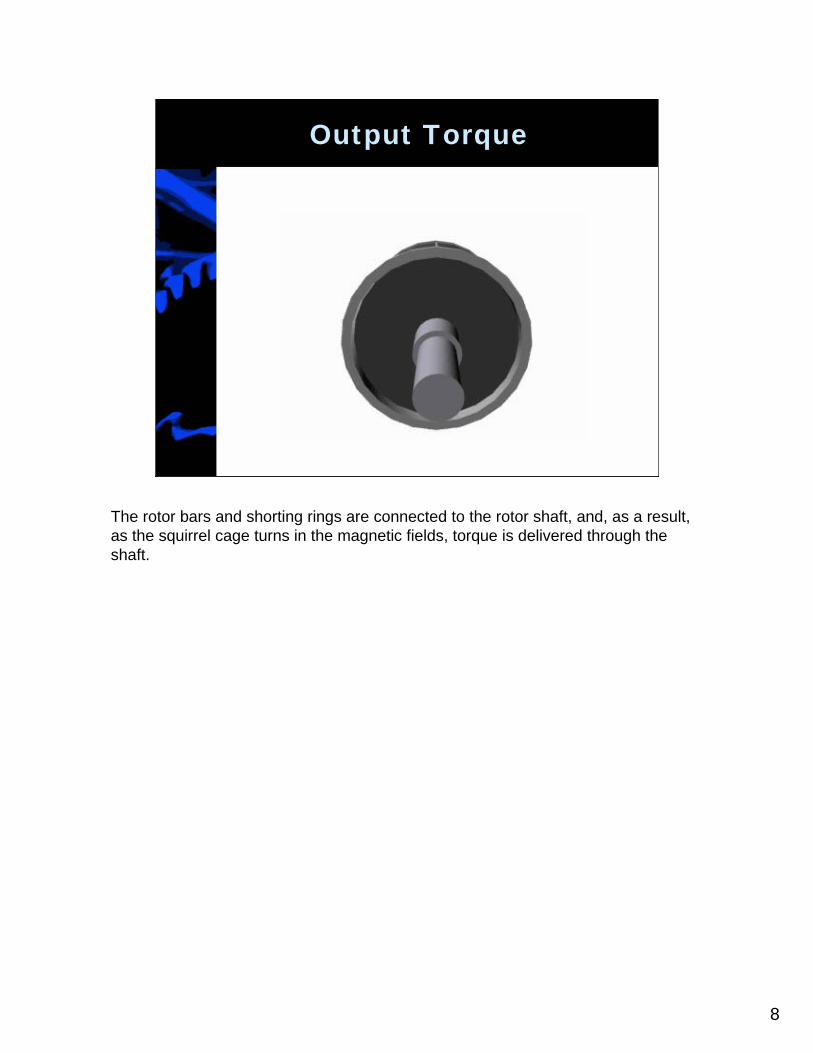
Output Torque
The rotor bars and shorting rings are connected to the rotor shaft, and, as a result, as the squirrel cage turns in the magnetic fields, torque is delivered through the shaft.
9
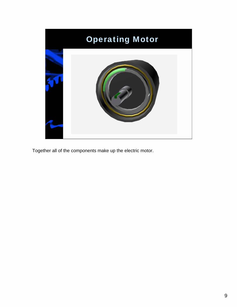
Operating Motor
Together all of the components make up the electric motor.
10
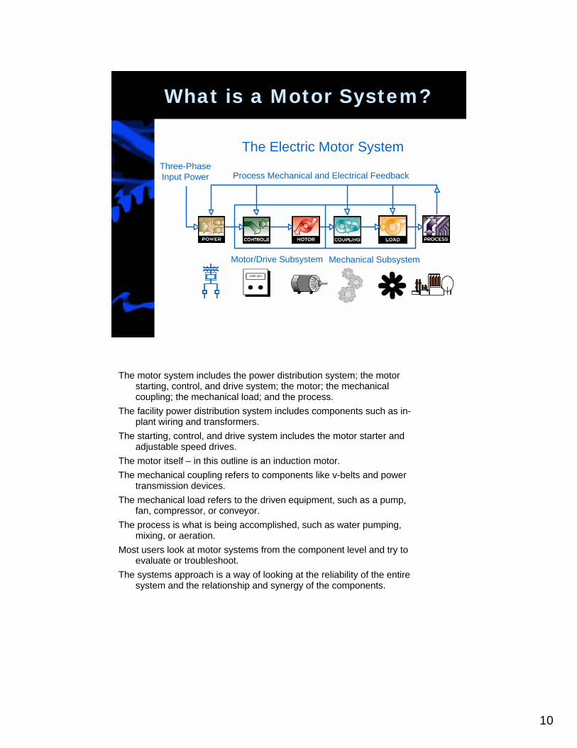
The motor system includes the power distribution system; the motor starting, control, and drive system; the motor; the mechanical coupling; the mechanical load; and the process.
The facility power distribution system includes components such as in-plant wiring and transformers.
The starting, control, and drive system includes the motor starter and adjustable speed drives.
The motor itself – in this outline is an induction motor.The mechanical coupling refers to components like v-belts and power
transmission devices.The mechanical load refers to the driven equipment, such as a pump,
fan, compressor, or conveyor.The process is what is being accomplished, such as water pumping,
mixing, or aeration.Most users look at motor systems from the component level and try to
evaluate or troubleshoot.The systems approach is a way of looking at the reliability of the entire
system and the relationship and synergy of the components.
What is a Motor System?
The Electric Motor SystemThree-PhaseInput Power Process Mechanical and Electrical Feedback
Motor/Drive Subsystem Mechanical Subsystem1200 rpm
11
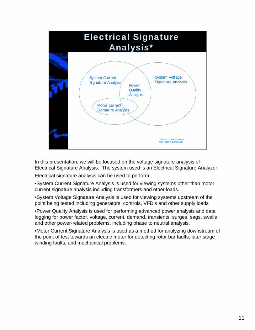
Electrical Signature Analysis*
Motor CurrentSignature Analysis
System CurrentSignature Analysis
PowerQualityAnalysis
System VoltageSignature Analysis
*Source: Howard HaynesOak Ridge National Labs
In this presentation, we will be focused on the voltage signature analysis ofElectrical Signature Analysis. The system used is an Electrical Signature Analyzer.Electrical signature analysis can be used to perform:•System Current Signature Analysis is used for viewing systems other than motor current signature analysis including transformers and other loads.•System Voltage Signature Analysis is used for viewing systems upstream of the point being tested including generators, controls, VFD’s and other supply loads•Power Quality Analysis is used for performing advanced power analysis and data logging for power factor, voltage, current, demand, transients, surges, sags, swells and other power-related problems, including phase to neutral analysis.•Motor Current Signature Analysis is used as a method for analyzing downstream of the point of test towards an electric motor for detecting rotor bar faults, later stage winding faults, and mechanical problems.
12
Airgap - Current
Howard W Penrose, Ph.D., RCM2T-Solutions, Inc.
The area that needs to be concentrated on, in order to understand electrical signature analysis, is the motor airgap and how it effect current.

13
Magnetic Fields
• Strength Decreases by Square of Distance from Source
• Line Frequency is provided to motor (load)
• Motor converts Voltage frequency to Current frequency. Defects in motor generate additional current frequencies.
• Line Frequency acts as Carrier Frequency
In order to understand how ESA works, it is important to know a few rules as to how magnetic fields, current and the supply frequency work to produce the signal we analyze.
First, the strength of the magnetic field decreases by the square of the distance from the source. This means, that as the rotor bars recede or approach the stator magnetic fields, it will result in a change to the current in the stator.
A line frequency voltage is provided to the motor.
The motor converts the voltage frequency to the current frequency. Any defects in the motor or load generate additional frequencies within the current. In effect, the motor is a fault generator.
The line frequency acts as the carrier frequency which can be put through a fast fourier transform, or FFT, in order to pull the amplitude modulated frequencies out for analysis in an amplitude versus frequency spectra.

14
Good Airgap
In a perfect motor, the rotor is centered in the stator and all of the fields are even. If a perfect voltage sine wave is introduced, a perfect current sine wave results.If there are any defect frequencies in the voltage sine wave, then those frequencies will appear in the current FFT, but at a smaller magnitude due to the dampening effect through the motor and fields. In order to compare equivalent magnitudes, the results of both are shown in dB.When looking around the line frequency, it is common to ‘demodulate’ or remove the carrier frequency in order to look at the low frequency issues in the motor current.
15
Static Eccentricity
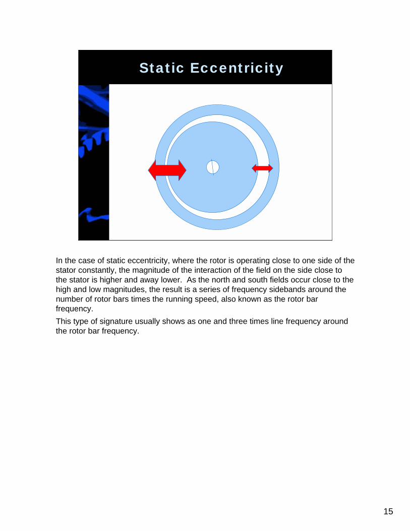
In the case of static eccentricity, where the rotor is operating close to one side of the stator constantly, the magnitude of the interaction of the field on the side close to the stator is higher and away lower. As the north and south fields occur close to the high and low magnitudes, the result is a series of frequency sidebands around the number of rotor bars times the running speed, also known as the rotor bar frequency.This type of signature usually shows as one and three times line frequency around the rotor bar frequency.
16
Dynamic Eccentricity
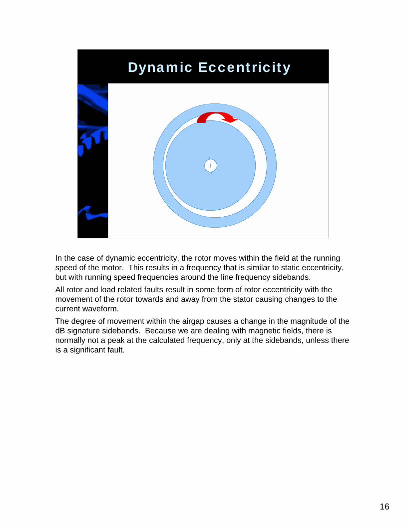
In the case of dynamic eccentricity, the rotor moves within the field at the running speed of the motor. This results in a frequency that is similar to static eccentricity, but with running speed frequencies around the line frequency sidebands.All rotor and load related faults result in some form of rotor eccentricity with the movement of the rotor towards and away from the stator causing changes to the current waveform.The degree of movement within the airgap causes a change in the magnitude of the dB signature sidebands. Because we are dealing with magnetic fields, there is normally not a peak at the calculated frequency, only at the sidebands, unless there is a significant fault.

17
Effect on Shaft
The shaft and rotor in the motor is not truly rigid. It moves.One cause of movement is unbalance which puts a force on the rotor and resulting movement in the airgap.Another cause is outside forces on the shaft, such as misalignment, belt tensioning, etc.Torque on the output shaft will also cause the rotor to flex within the airgap, usually causing a raised noise floor around the line frequency or other frequencies.Hot spots in the rotor will cause the rotor to bend causing dynamic eccentricity.

18
Line Frequency Amplitude Modulation (LF = Carrier)
mc
mcmcc tbCostbCostCosS
ωω
ωωωωω
−+
−+++= )(21)(
21
Sidebands: Intensity proportional to strength!
xLFRPM
RPMRPMPPFs
rs )(2 −=
Rotor fault sidebands: Twice Slip Frequency
In a quick overview, the modulated carrier frequency is the line frequency. As a result higher frequency faults will end up as multiples of the rotor bars and running speed for rotating problems and stator slots and running speed for stator problems. In almost all cases, there will be sidebands of the line frequency as it is the carrier frequency. The amplitude of these sidebands are relative to the magnitude of the fault.Rotor bar faults, one of the strengths of ESA, show as sidebands of twice slip frequency around the line frequency current.
19
Rule of DC Analysis
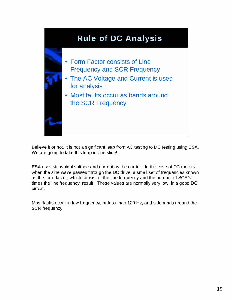
• Form Factor consists of Line Frequency and SCR Frequency
• The AC Voltage and Current is used for analysis
• Most faults occur as bands around the SCR Frequency
Believe it or not, it is not a significant leap from AC testing to DC testing using ESA. We are going to take this leap in one slide!
ESA uses sinusoidal voltage and current as the carrier. In the case of DC motors, when the sine wave passes through the DC drive, a small set of frequencies known as the form factor, which consist of the line frequency and the number of SCR’s times the line frequency, result. These values are normally very low, in a good DC circuit.
Most faults occur in low frequency, or less than 120 Hz, and sidebands around the SCR frequency.
20
Performing an Analysis
Howard W Penrose, Ph.D.T-Solutions, Inc.
Knowing this, we will run through a short analysis of a DC system utilizing an RCM-Based approach.

21
Gears
1750 RPM
10 Teeth
20 Teeth
25 Teeth
RPMRPMxTeethTeeth 8751750
2010
=
RPMRPMxTeethTeeth 700875
2520
=
Gearbox = Torque Multiplier
As the system we will be analyzing includes gears, we will quickly discuss gear ratios.
In a system that has a series of gears which include a 10 tooth gear, 20 tooth gear and 25 tooth gear, the intitial RPM is 1750, the reduced mid-speed is 875 RPM and the output speed is 700 RPM. The related frequencies are these speeds divided by 60 Hz.

22
Example
DCMotor
Shaft w/ coupling
1800 RPM, 500V Armature
Gears3.71 Ratio
Output Shaft485 RPM MaxBearings and Seals
4 Propellors
The system under review consists of a DC drive, a DC motor, a shaft with a coupling, a right angle gear with a 3.71 gear ratio, an output shaft that has bearings and mechanical seals and a four blade propellor on the output.The max speed is 1800 RPM on the DC motor and 485 RPM on the output shaft.

23
How to Walk Through an Analysis
• Determine components of the system
• Basic Failure Modes and Effects Analysis
• Determine Associated Fault Frequencies
• Analyze data
The way that I have successfully walked through most analysis on systems include four basic steps:
1. Determine the components of the system2. Determine the basic failure modes and effects of the system3. Determine the associated fault frequencies of the most common faults4. Analyze the data and FFT’s

24
Components of System
• Voltage Signature– DC Drive
• Current Signature– DC Motor– Couplings– Shaft– Gears– Bearings– Seals– Propellor
When reviewing the system, the components are as follow:
Voltage signature issues identify problems in the DC drive.
In Current, the following components are reviewed:•The DC motor•Couplings•Shaft•Gears•Bearings•Seals•Propellor
25
FMEA
• Determine all possible failures– Functional System– Functional Hidden
• Determine probability• Analyze for probable faults
– 20% of failures will be 80% of findings• Analyze less likely faults later
In the Failure Modes and Effects Analysis, the following is performed:•Determine all possible failures, both obvious and hidden•Determine the probability•Understand that 20% of the potential faults will be 80% of the findings•Analyze less likely faults if the primary faults do not show, in the instance of troubleshooting.
26
DC Drive Faults
• Failures– SCR Failure – Fields– SCR Failure – Armature– Firing Cards – Fields– Firing Cards – Armature– Loss of incoming phase
• Functional Issues– Loss of fields – overspeed or loss of torque– Loss of Armature – torsional pulsation or loss
of speed– Loss of incoming phase – Rectifying issues
With the DC drive, the possible faults include:•SCR Failure for either the fields or armature•Firing cards for the fields or armature•The loss of an incoming phase
The functional issues show as:•Overspeed or loss of torque due to a loss of the fields•Torsional pulsation or loss of speed due to armature issues•The loss of an incoming phase results in rectifying issues
27
DC Motor Faults
• Fields– Shorted fields: Overspeed/Reduced Torque– Grounded fields: Same
• Armature– Brushes– Commutator worn– Grounded– Shorted– Bearings– Unbalance
DC motor faults include:
In the fields:•Shorted fields which result in overspeed or reduced torque•Grounded fields will end with the same
In the armature:•Brushes, commutator wear, grounding, shorted coils, failing bearings or unbalance.

28
Driven Equipment
• Coupling Misalignment• Driver (Before Gears)
– Bearings– Seals
• Gears– Backlash– Broken Teeth
• Driven (After Gears)– Bearings– Seals
• Propellor
In the driven equipment, the following issues may result:•Coupling misalignment•Bearings and seals of the driven shaft before the gears•Gear backlash or broken or cracked gear teeth•Bearings and seals of the output shaft•Propellor blade or cavitation problems
29
Most Likely Faults
• VSA– Armature Drive Circuit – SCR or Firing Card
• ESA– DC Motor
• Brushes and Comm• Grounded• Unbalance
– Load• Misalignment• Seals• Gears• Propellor Blades
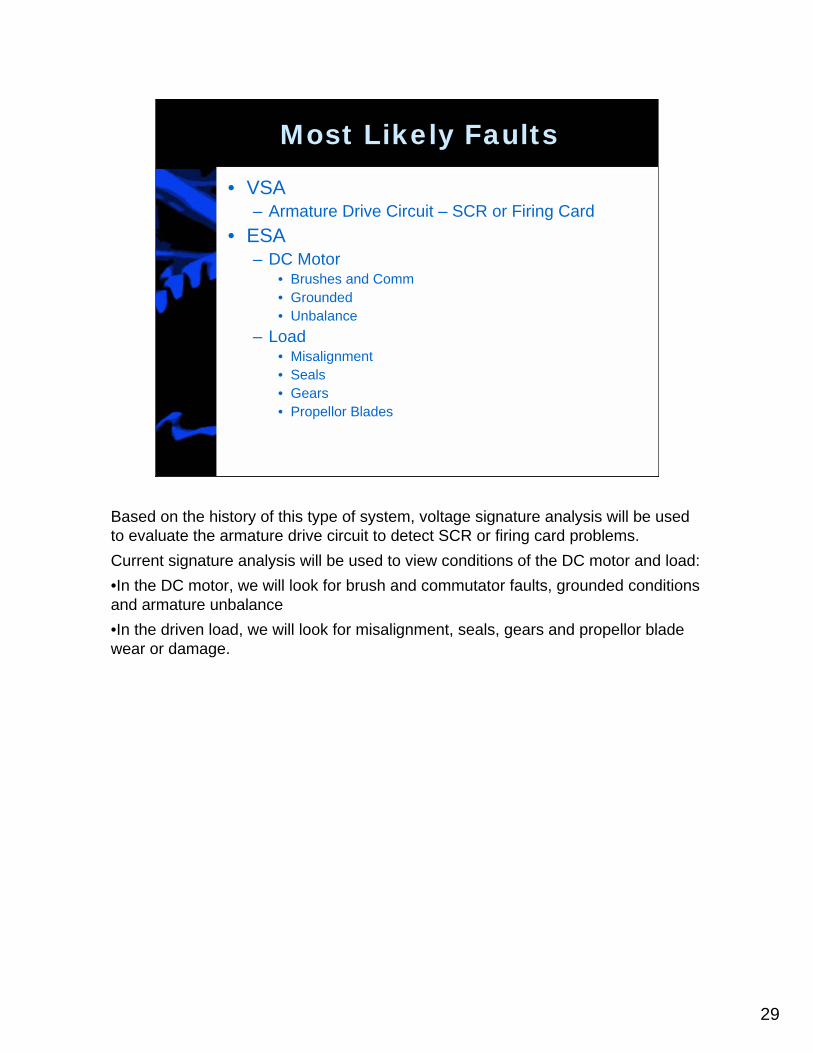
Based on the history of this type of system, voltage signature analysis will be used to evaluate the armature drive circuit to detect SCR or firing card problems.Current signature analysis will be used to view conditions of the DC motor and load:•In the DC motor, we will look for brush and commutator faults, grounded conditions and armature unbalance•In the driven load, we will look for misalignment, seals, gears and propellor blade wear or damage.
30
Clean Signatures (DC)
• Voltage and Current High Frequency– Line Frequency with degrading harmonics– SCR Frequency with degrading harmonics
• Current Low Frequency– Running Speed – Low– Possible turbulence
• Estimated running speed:
edRunningSpeRPMxNameplateoltageNameplateVageActualVolt
=
ESAAnalysis of
System
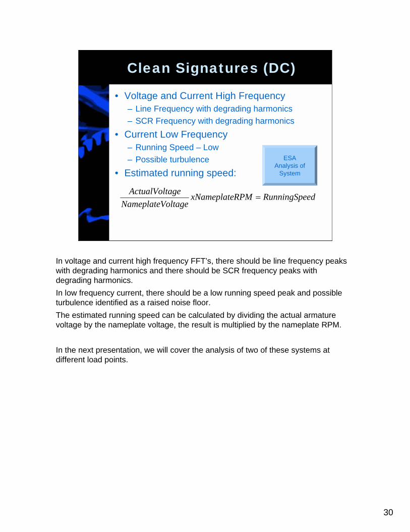
In voltage and current high frequency FFT’s, there should be line frequency peaks with degrading harmonics and there should be SCR frequency peaks with degrading harmonics.In low frequency current, there should be a low running speed peak and possible turbulence identified as a raised noise floor.The estimated running speed can be calculated by dividing the actual armature voltage by the nameplate voltage, the result is multiplied by the nameplate RPM.
In the next presentation, we will cover the analysis of two of these systems at different load points.

31
135 Hanbury Rd, Suite C-1Chesapeake, VA 23320
ph: 757-410-0233/0350fax: 757-410-7809
Howard W Penrose, Ph.D.Vice President, Electrical Reliability [email protected]/fax: 860-577-8537
Website:http://www.tsoln-inc.com
T-Solutions, Inc.
For more information on the development of your maintenance and reliability programs, contact:
T-Solutions, 135 Hanbury rd, suite c1, Chesapeake, virginia. Phone 757-410-0233 or go to our website: http://www.tsoln-inc.com.
For direct information on the development of your motor management program or service, contact Howard Penrose, Vice President of electrical reliability programs at [email protected] or phone 860-577-8537
Join us for a three day class on motor systems maintenance and management on April 6-8, 2005, at the Crowne Plaza Metro Airport in Romulus, Michigan.

Is your maintenance program effective? If not, what is preventing its success?
Join the leaders in maintenance and reliability for a three day seminar taught in
an open classroom environment. Bring your questions and an appetite to
learn. Learn to be more proactive in your maintenance programs by selecting
the right maintenance, on the right equipment, at the right time, for the right
reasons using a simple process.
At the completion of this seminar, the attendee will have the tools and
knowledge to have an immediate impact on the reliability of your motor
systems and your bottom line! Review and correct your maintenance, repair
vendor issues, best practices, repetitive failures and more!
Dr. Penrose has over 20 years in the electric motor industry from motor repair
to advanced reliability research and applications using modern CBM and
maintenance technologies.
T-Solutions, Inc. provides the Knowledge,
Understanding and Experience of the
Maintenance and Reliability Professional!
T-SOLUTIONS, INC.
Electric Motor System Maintenance and Management Workshop 93% of Motor Management
Programs Fail!
66% of PdM Recommendations are Ignored!
Properly Implemented Programs Have ROI Measured in Days!
135 Hanbury Rd, Suite C-1 Chesapeake, VA 23322
Phone: 757-410-0233 Fax: 757-410-7809
E-mail: [email protected] Web: http://www.tsoln-inc.com
T-SOLUTIONS, INC.
Topics Covered In Class:
Basic Motor Systems Basic System Maintenance
Condition Based Monitoring Technologies and Capabilities
RCM-Based Motor Management Setting Condemning Criteria Time To Failure Estimation
Selecting Test Frequencies for CBM Root-Cause-Failure-Analysis
Repair vs Replace
Who Should Attend?
Maintenance and Reliability Professionals, Planners, Managers
and others with motor system maintenance responsibilities
The Instructor: Howard W Penrose, Ph.D. The Dates: April 6-8, 2005 Where:
Crowne Plaza Detroit Metro Airport 8000 Merriman Road Romulus, MI 48174
Room Rate: $119 per night
Cost: $1,495 per person, check or PO.
Reserve your place early! Limited Attendance!
See Next Page for Reservation Information

Motor Management Workshop
The Dates: April 6-8, 2005 Where:
Crowne Plaza Detroit Metro Airport 8000 Merriman Road Romulus, MI 48174
Room Rate: $119 per night
Cost: $1,495 per person, check or PO.
Hotel reservations can be made by calling Crowne Plaza between Monday and Friday from 9am to 4pm EST and identify that you are making a reservation under Motor Management. The rate is $119 per night plus 14% sales and occupancy tax. This rate is available for April 4 through 8, 2005. Ph: (734) 729-2600 ext 7160 The Crowne Plaza Detroit Metro Airport is directly across from the Detroit Metro Airport with hotel transportation available.
Reservation Form
Name ______________________________________________ Company ______________________________________________ Address ______________________________________________ ______________________________________________ City _____________________ State/Province __________ Phone _____________________ Fax ____________________ Email ______________________________________________ Additional Attendees: ____________________________________ ______________________________________________
___ Purchase Order to Follow ___ Purchase Order Attached ___ Check to Follow ___ Check Enclosed
Make Checks or Purchase Orders to: T-Solutions, Inc. 135 Hanbury Rd, Suite C-1 Chesapeake, VA 23322 Ph: 757-410-0233 Fax: 757-410-7809 Email: [email protected] Web: http://www.tsoln-inc.com
Reserve Your Place Contact Charlene Beamon or
Michael McHenry by phone, fax this form to us or email now! [email protected]
T-Solutions, Inc. 135 Hanbury Rd, Suite C-1
Chesapeake, VA 23322
Ph: 757-410-0233 Fax: 757-410-7809
Email: [email protected]
Web: http://www.tsoln-inc.com
Instructor: Howard W Penrose, Ph.D.
Note: Agenda will vary as necessary
Electric Motor System Maintenance and Management Workshop
Wednesday, April 6, 2005
7:30am – 8:00am Continental Breakfast in Classroom
8:00am – 8:20am Introductions and attendees
8:20am – 9:00am *Basic electricity for electric motors
9:00am – 9:45am *Basic Electromagnetism and AC Induction Motor System Theory
9:45am – 10:00am Break
10:00am – 11:00am *Basic Electromagnetism and AC Induction Motor System Theory (Continued)
11:00am- 11:30am *Electrical Insulation System Theory
11:30am – 12 noon *Electric Motor Bearings
12 noon – 12:45pm Boxed Lunch
12:45pm – 2:15pm Traditional Electrical and Mechanical Maintenance Practices for Active and Spare Motors
2:15pm – 2:30pm Break
2:30pm – 4:00pm Electrical and Mechanical Condition-Based Monitoring Technologies and Capabilities (MCA, ESA, Infrared, Vibration, Insulation Testing, etc.)
4:00pm – 4:30pm General Discussion and Homework Assignment
*Does not require any electrical or mechanical maintenance background. Required basic principles for understanding class materials and goals.
©2005, T-Solutions, Inc.
©2005, T-Solutions, Inc.
Thursday, April 7, 2005
7:30am – 8:00am Continental Breakfast in Classroom
8:00am – 8:20am Homework Discussion
8:20am – 9:45am Principles of Classical RCM
9:45am – 10:00am Break
10:00am – 12 noon Principles of Classical RCM and Backfit RCM
12 noon – 12:45pm Lunch
12:45pm – 2:15pm Applying RCM Principles to Motor Maintenance
2:15pm – 2:30pm Break
2:30pm – 4:00pm Setting Condemning Criteria
4:00PM – 4:30PM General Discussion and Homework Assignment
Friday, April 8, 2005
7:30am – 8:00am Breakfast in Classroom
8:00am – 8:15am Homework Discussion
8:15am – 9:45am Time to Failure Estimation (TTFE)
9:45am – 10:00am Break
10:00am – 11:00am TTFE and Selecting Test Frequencies for Maintenance Practices
11:00am – 12 noon Root-Cause-Failure Analysis on Motor Systems
12:00 noon – 12:45pm Lunch
12:45pm – 1:30pm Root-Cause-Failure Analysis on Motor Systems (Continued)
1:30pm – 2:15pm Repair vs Replace Decisions and Tools
2:15pm – 2:30pm Break
2:30pm – 4:00pm Working with Vendors for Program Success