Embed Size (px)
Citation preview

872019 electrical transformers basics
httpslidepdfcomreaderfullelectrical-transformers-basics 15
2 Basic Principles
As mentioned earlier the transformer is a static device working on the principle of
Faradayrsquos law of induction Faradayrsquos law states that a voltage appears across the terminals
of an electric coil when the flux linkages associated with the same changes This emf is
proportional to the rate of change of flux linkages Putting mathematically
e =dψ
dt(1)
Where e is the induced emf in volt and ψ is the flux linkages in Weber turn Fig 1 shows a
Figure 1 Flux linkages of a coil
coil of N turns All these N turns link flux lines of φ Weber resulting in the Nφ flux linkages
In such a case
ψ = Nφ (2)
and
e = N dφ
dtvolt (3)
The change in the flux linkage can be brought about in a variety of ways
bull coil may be static and unmoving but the flux linking the same may change with time
3
872019 electrical transformers basics
httpslidepdfcomreaderfullelectrical-transformers-basics 25
bull flux lines may be constant and not changing in time but the coil may move in space
linking different value of flux with time
bullboth 1 and 2 above may take place The flux lines may change in time with coil moving
in space
These three cases are now elaborated in sequence below with the help of a coil with a simple
geometry
L
B
X
+-
Figure 2 Static coil
Fig 2 shows a region of length L m of uniform flux density B Tesla the
flux lines being normal to the plane of the paper A loop of one turn links part of this flux
The flux φ linked by the turn is L lowastB lowastX Weber Here X is the length of overlap in meters
as shown in the figure If now B does not change with time and the loop is unmoving then
no emf is induced in the coil as the flux linkages do not change Such a condition does notyield any useful machine On the other hand if the value of B varies with time a voltage is
induced in the coil linking the same coil even if the coil does not move The magnitude of B
4
872019 electrical transformers basics
httpslidepdfcomreaderfullelectrical-transformers-basics 35
is assumed to be varying sinusoidally and can be expressed as
B = Bm sin ωt (4)
where Bm is the peak amplitude of the flux density ω is the angular rate of change withtime Then the instantaneous value of the flux linkage is given by
ψ = Nφ = NLXBm sin ωt (5)
The instantaneous value of the induced emf is given by
e =dψ
dt= Nφmω cos ωt = Nφmω sin(ωt +
π
2) (6)
Here φm = BmLX The peak value of the induced emf is
em = Nφmω (7)
and the rms value is given by
E =Nφmωradic
2volt
Further this induced emf has a phase difference of π2 radian with respect to the
flux linked by the turn This emf is termed as lsquotransformerrsquo emf and this principle is used
in a transformer Polarity of the emf is obtained by the application of Lenzrsquos law Lenzrsquos
law states that the reaction to the change in the flux linkages would be such as to oppose
the cause The emf if permitted to drive a current would produce a counter mmf to oppose
this changing flux linkage In the present case presented in Fig 2 the flux linkages are
assumed to be increasing The polarity of the emf is as indicated The loop also experiences
a compressive force
Fig 2(b) shows the same example as above but with a small difference The flux
density is held constant at B Tesla The flux linked by the coil at the current position is
5
872019 electrical transformers basics
httpslidepdfcomreaderfullelectrical-transformers-basics 45
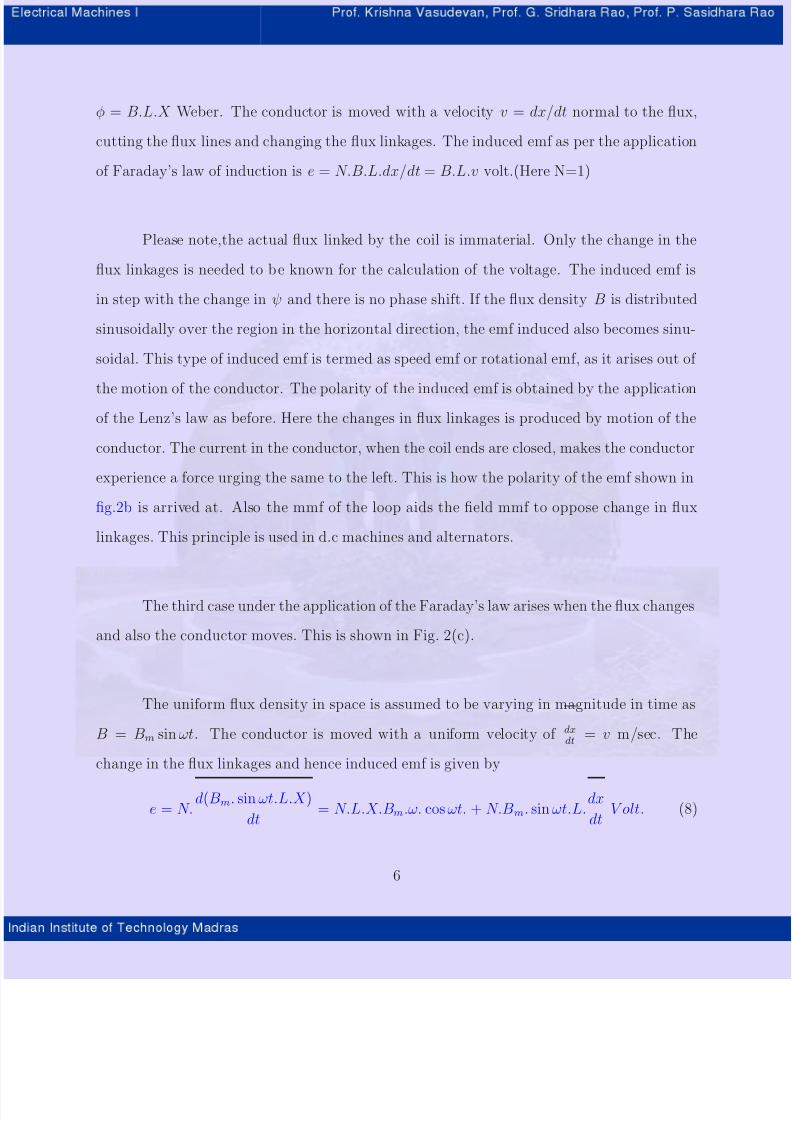
φ = BLX Weber The conductor is moved with a velocity v = dxdt normal to the flux
cutting the flux lines and changing the flux linkages The induced emf as per the application
of Faradayrsquos law of induction is e = NBLdxdt = BLv volt(Here N=1)
Please notethe actual flux linked by the coil is immaterial Only the change in the
flux linkages is needed to be known for the calculation of the voltage The induced emf is
in step with the change in ψ and there is no phase shift If the flux density B is distributed
sinusoidally over the region in the horizontal direction the emf induced also becomes sinu-
soidal This type of induced emf is termed as speed emf or rotational emf as it arises out of
the motion of the conductor The polarity of the induced emf is obtained by the applicationof the Lenzrsquos law as before Here the changes in flux linkages is produced by motion of the
conductor The current in the conductor when the coil ends are closed makes the conductor
experience a force urging the same to the left This is how the polarity of the emf shown in
fig2b is arrived at Also the mmf of the loop aids the field mmf to oppose change in flux
linkages This principle is used in dc machines and alternators
The third case under the application of the Faradayrsquos law arises when the flux changes
and also the conductor moves This is shown in Fig 2(c)
The uniform flux density in space is assumed to be varying in magnitude in time as
B = Bm sin ωt The conductor is moved with a uniform velocity of dxdt
= v msec The
change in the flux linkages and hence induced emf is given by
e = Nd(Bm sin ωtLX )
dt= NLXBmω cos ωt + NBm sin ωtL
dx
dtV olt (8)
6
872019 electrical transformers basics
httpslidepdfcomreaderfullelectrical-transformers-basics 55
The first term is due to the changing flux and hence is a transformer emf The second
term is due to moving conductor or is a speed emf When the terminals are closed such as
to permit a current the conductor experiences a force and also the mmf of the coil opposes
the change in flux linkages This principle is used in ac machines where the field is time
varying and conductors are moving under the same
The first case where there is a time varying field and a stationary coil resulting in
a transformer emf is the subject matter in the present section The case two will be re-
visited under the study of the dc machines and synchronous machines Case three will be
extensively used under the study of ac machines such as induction machines and also in accommutator machines
Next in the study of the transformers comes the question of creating a time varying
filed This is easily achieved by passing a time varying current through a coil The winding
which establishes the field is called the primary The other winding which is kept in that
field and has a voltage induced in it is called a secondary It should not be forgotten that
the primary also sees the same time varying field set up by it linking its turns and has an
induced emf in the same These aspects will be examined in the later sections At first
the common constructional features of a transformer used in electric power supply system
operating at 50 Hz are examined
7

872019 electrical transformers basics
httpslidepdfcomreaderfullelectrical-transformers-basics 25
bull flux lines may be constant and not changing in time but the coil may move in space
linking different value of flux with time
bullboth 1 and 2 above may take place The flux lines may change in time with coil moving
in space
These three cases are now elaborated in sequence below with the help of a coil with a simple
geometry
L
B
X
+-
Figure 2 Static coil
Fig 2 shows a region of length L m of uniform flux density B Tesla the
flux lines being normal to the plane of the paper A loop of one turn links part of this flux
The flux φ linked by the turn is L lowastB lowastX Weber Here X is the length of overlap in meters
as shown in the figure If now B does not change with time and the loop is unmoving then
no emf is induced in the coil as the flux linkages do not change Such a condition does notyield any useful machine On the other hand if the value of B varies with time a voltage is
induced in the coil linking the same coil even if the coil does not move The magnitude of B
4
872019 electrical transformers basics
httpslidepdfcomreaderfullelectrical-transformers-basics 35
is assumed to be varying sinusoidally and can be expressed as
B = Bm sin ωt (4)
where Bm is the peak amplitude of the flux density ω is the angular rate of change withtime Then the instantaneous value of the flux linkage is given by
ψ = Nφ = NLXBm sin ωt (5)
The instantaneous value of the induced emf is given by
e =dψ
dt= Nφmω cos ωt = Nφmω sin(ωt +
π
2) (6)
Here φm = BmLX The peak value of the induced emf is
em = Nφmω (7)
and the rms value is given by
E =Nφmωradic
2volt
Further this induced emf has a phase difference of π2 radian with respect to the
flux linked by the turn This emf is termed as lsquotransformerrsquo emf and this principle is used
in a transformer Polarity of the emf is obtained by the application of Lenzrsquos law Lenzrsquos
law states that the reaction to the change in the flux linkages would be such as to oppose
the cause The emf if permitted to drive a current would produce a counter mmf to oppose
this changing flux linkage In the present case presented in Fig 2 the flux linkages are
assumed to be increasing The polarity of the emf is as indicated The loop also experiences
a compressive force
Fig 2(b) shows the same example as above but with a small difference The flux
density is held constant at B Tesla The flux linked by the coil at the current position is
5
872019 electrical transformers basics
httpslidepdfcomreaderfullelectrical-transformers-basics 45
φ = BLX Weber The conductor is moved with a velocity v = dxdt normal to the flux
cutting the flux lines and changing the flux linkages The induced emf as per the application
of Faradayrsquos law of induction is e = NBLdxdt = BLv volt(Here N=1)
Please notethe actual flux linked by the coil is immaterial Only the change in the
flux linkages is needed to be known for the calculation of the voltage The induced emf is
in step with the change in ψ and there is no phase shift If the flux density B is distributed
sinusoidally over the region in the horizontal direction the emf induced also becomes sinu-
soidal This type of induced emf is termed as speed emf or rotational emf as it arises out of
the motion of the conductor The polarity of the induced emf is obtained by the applicationof the Lenzrsquos law as before Here the changes in flux linkages is produced by motion of the
conductor The current in the conductor when the coil ends are closed makes the conductor
experience a force urging the same to the left This is how the polarity of the emf shown in
fig2b is arrived at Also the mmf of the loop aids the field mmf to oppose change in flux
linkages This principle is used in dc machines and alternators
The third case under the application of the Faradayrsquos law arises when the flux changes
and also the conductor moves This is shown in Fig 2(c)
The uniform flux density in space is assumed to be varying in magnitude in time as
B = Bm sin ωt The conductor is moved with a uniform velocity of dxdt
= v msec The
change in the flux linkages and hence induced emf is given by
e = Nd(Bm sin ωtLX )
dt= NLXBmω cos ωt + NBm sin ωtL
dx
dtV olt (8)
6
872019 electrical transformers basics
httpslidepdfcomreaderfullelectrical-transformers-basics 55
The first term is due to the changing flux and hence is a transformer emf The second
term is due to moving conductor or is a speed emf When the terminals are closed such as
to permit a current the conductor experiences a force and also the mmf of the coil opposes
the change in flux linkages This principle is used in ac machines where the field is time
varying and conductors are moving under the same
The first case where there is a time varying field and a stationary coil resulting in
a transformer emf is the subject matter in the present section The case two will be re-
visited under the study of the dc machines and synchronous machines Case three will be
extensively used under the study of ac machines such as induction machines and also in accommutator machines
Next in the study of the transformers comes the question of creating a time varying
filed This is easily achieved by passing a time varying current through a coil The winding
which establishes the field is called the primary The other winding which is kept in that
field and has a voltage induced in it is called a secondary It should not be forgotten that
the primary also sees the same time varying field set up by it linking its turns and has an
induced emf in the same These aspects will be examined in the later sections At first
the common constructional features of a transformer used in electric power supply system
operating at 50 Hz are examined
7

872019 electrical transformers basics
httpslidepdfcomreaderfullelectrical-transformers-basics 35
is assumed to be varying sinusoidally and can be expressed as
B = Bm sin ωt (4)
where Bm is the peak amplitude of the flux density ω is the angular rate of change withtime Then the instantaneous value of the flux linkage is given by
ψ = Nφ = NLXBm sin ωt (5)
The instantaneous value of the induced emf is given by
e =dψ
dt= Nφmω cos ωt = Nφmω sin(ωt +
π
2) (6)
Here φm = BmLX The peak value of the induced emf is
em = Nφmω (7)
and the rms value is given by
E =Nφmωradic
2volt
Further this induced emf has a phase difference of π2 radian with respect to the
flux linked by the turn This emf is termed as lsquotransformerrsquo emf and this principle is used
in a transformer Polarity of the emf is obtained by the application of Lenzrsquos law Lenzrsquos
law states that the reaction to the change in the flux linkages would be such as to oppose
the cause The emf if permitted to drive a current would produce a counter mmf to oppose
this changing flux linkage In the present case presented in Fig 2 the flux linkages are
assumed to be increasing The polarity of the emf is as indicated The loop also experiences
a compressive force
Fig 2(b) shows the same example as above but with a small difference The flux
density is held constant at B Tesla The flux linked by the coil at the current position is
5
872019 electrical transformers basics
httpslidepdfcomreaderfullelectrical-transformers-basics 45
φ = BLX Weber The conductor is moved with a velocity v = dxdt normal to the flux
cutting the flux lines and changing the flux linkages The induced emf as per the application
of Faradayrsquos law of induction is e = NBLdxdt = BLv volt(Here N=1)
Please notethe actual flux linked by the coil is immaterial Only the change in the
flux linkages is needed to be known for the calculation of the voltage The induced emf is
in step with the change in ψ and there is no phase shift If the flux density B is distributed
sinusoidally over the region in the horizontal direction the emf induced also becomes sinu-
soidal This type of induced emf is termed as speed emf or rotational emf as it arises out of
the motion of the conductor The polarity of the induced emf is obtained by the applicationof the Lenzrsquos law as before Here the changes in flux linkages is produced by motion of the
conductor The current in the conductor when the coil ends are closed makes the conductor
experience a force urging the same to the left This is how the polarity of the emf shown in
fig2b is arrived at Also the mmf of the loop aids the field mmf to oppose change in flux
linkages This principle is used in dc machines and alternators
The third case under the application of the Faradayrsquos law arises when the flux changes
and also the conductor moves This is shown in Fig 2(c)
The uniform flux density in space is assumed to be varying in magnitude in time as
B = Bm sin ωt The conductor is moved with a uniform velocity of dxdt
= v msec The
change in the flux linkages and hence induced emf is given by
e = Nd(Bm sin ωtLX )
dt= NLXBmω cos ωt + NBm sin ωtL
dx
dtV olt (8)
6
872019 electrical transformers basics
httpslidepdfcomreaderfullelectrical-transformers-basics 55
The first term is due to the changing flux and hence is a transformer emf The second
term is due to moving conductor or is a speed emf When the terminals are closed such as
to permit a current the conductor experiences a force and also the mmf of the coil opposes
the change in flux linkages This principle is used in ac machines where the field is time
varying and conductors are moving under the same
The first case where there is a time varying field and a stationary coil resulting in
a transformer emf is the subject matter in the present section The case two will be re-
visited under the study of the dc machines and synchronous machines Case three will be
extensively used under the study of ac machines such as induction machines and also in accommutator machines
Next in the study of the transformers comes the question of creating a time varying
filed This is easily achieved by passing a time varying current through a coil The winding
which establishes the field is called the primary The other winding which is kept in that
field and has a voltage induced in it is called a secondary It should not be forgotten that
the primary also sees the same time varying field set up by it linking its turns and has an
induced emf in the same These aspects will be examined in the later sections At first
the common constructional features of a transformer used in electric power supply system
operating at 50 Hz are examined
7
872019 electrical transformers basics
httpslidepdfcomreaderfullelectrical-transformers-basics 45
φ = BLX Weber The conductor is moved with a velocity v = dxdt normal to the flux
cutting the flux lines and changing the flux linkages The induced emf as per the application
of Faradayrsquos law of induction is e = NBLdxdt = BLv volt(Here N=1)
Please notethe actual flux linked by the coil is immaterial Only the change in the
flux linkages is needed to be known for the calculation of the voltage The induced emf is
in step with the change in ψ and there is no phase shift If the flux density B is distributed
sinusoidally over the region in the horizontal direction the emf induced also becomes sinu-
soidal This type of induced emf is termed as speed emf or rotational emf as it arises out of
the motion of the conductor The polarity of the induced emf is obtained by the applicationof the Lenzrsquos law as before Here the changes in flux linkages is produced by motion of the
conductor The current in the conductor when the coil ends are closed makes the conductor
experience a force urging the same to the left This is how the polarity of the emf shown in
fig2b is arrived at Also the mmf of the loop aids the field mmf to oppose change in flux
linkages This principle is used in dc machines and alternators
The third case under the application of the Faradayrsquos law arises when the flux changes
and also the conductor moves This is shown in Fig 2(c)
The uniform flux density in space is assumed to be varying in magnitude in time as
B = Bm sin ωt The conductor is moved with a uniform velocity of dxdt
= v msec The
change in the flux linkages and hence induced emf is given by
e = Nd(Bm sin ωtLX )
dt= NLXBmω cos ωt + NBm sin ωtL
dx
dtV olt (8)
6
872019 electrical transformers basics
httpslidepdfcomreaderfullelectrical-transformers-basics 55
The first term is due to the changing flux and hence is a transformer emf The second
term is due to moving conductor or is a speed emf When the terminals are closed such as
to permit a current the conductor experiences a force and also the mmf of the coil opposes
the change in flux linkages This principle is used in ac machines where the field is time
varying and conductors are moving under the same
The first case where there is a time varying field and a stationary coil resulting in
a transformer emf is the subject matter in the present section The case two will be re-
visited under the study of the dc machines and synchronous machines Case three will be
extensively used under the study of ac machines such as induction machines and also in accommutator machines
Next in the study of the transformers comes the question of creating a time varying
filed This is easily achieved by passing a time varying current through a coil The winding
which establishes the field is called the primary The other winding which is kept in that
field and has a voltage induced in it is called a secondary It should not be forgotten that
the primary also sees the same time varying field set up by it linking its turns and has an
induced emf in the same These aspects will be examined in the later sections At first
the common constructional features of a transformer used in electric power supply system
operating at 50 Hz are examined
7