Embed Size (px)
Citation preview
ELECTRICAL WATER HEATER
Installation, Use and conservation
TNC 10
TNC 15 TNC 30 TNC 50 TNC 80 TNC 80 H TNC 100 TNC 100 H TNC 150 TNC 150 H
We would like to congratulate and thank you for acquiring our product. The electrical thermoses COINTRA you have chosen has been designed and manufactured with great care by our specialists and carefully tested to meet your requirements.
To achieve the best performance from your new COINTRA electrical water heater and prolong its durability, we would advise you to read the instructions contained in this manual carefully.
This product conforms to EU Directive 2002796/EC The crossed out bin symbol reproduced in the appliance indicates that the product, at the end of its working life, should be treated separately from household waste, meaning that it has to be deposited in a selective waste centre for electrical and electronic appliances or it has to be returned to the
istributor when purchasing a new equivalent appliance dThe user is responsible for submitting the appliance, at the end of its
working life, to the established collection centres.
.
The correct ollection of the appliance, allowing the recycling of the appliance at the end of its working life in line with the environment, contributes to avoiding any possible negative impacts on the environment and health, nd fosters the recycling of the materials whereof the product is made up
c .
a.
For more detailed information about the collection systems available, please go to the collection facilities of the local bodies or the distributors where the purchase was made
TABLE OF CONTENTS PAGE
1. INSTALLATION, USE AND CONSERVATION INSTRUCTIONS ……… 3 1.1 General characteristics ……………………………………………… 3 1.2. Installation instructions ……………………………………………… 3 1.3. Product localisation ……………………………………………………3 1.4. Placement and securing ………………………………………………4 1.5. Installation of water system ....................................................….....4 1.6. Description of safety valve ……………………………………………4 1.7. Electrical installation ………………………………………………….. 5 1.8. Coming on line …………………………………………………………..5 1.9. Conservation …………………………………………………………….5 1.10. Thermostat adjustable from the exterior ………………………….5
2. PROHIBITION VOLUME AND PROTECTION VOLUME
3. GENERAL DIMENSIONS OF THE ELECTRICAL WATER HEATER
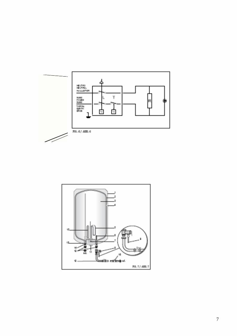
4. ELECTRICAL INSTALLATION DIAGRAM
5. OPERATING DIAGRAM 5.1. Vertical installation
6. TECHNICAL ASSISTANCE SERVICE 7. WARRANTY CERTIFICATE
2
I. INSTALLATION, USE AND CONSERVATION INSTRUCTIONS
The smooth operation of your thermos depends not only on the quality of the product but also on its correct installation by a qualified professional. 1.1. General characteristics MODELS: TNC-10, TNC-15, TNC-30, TNC-50, TNC-80, TNC-80 H, TNC-100, TNC-100 H TNC-150, TNC-50 H NOMINAL CAPACITY LITRES: 10, 15, 30, 50, 80, 100, 150 WEIGH WHEN FULL OF WATER* KG: 16, 23, 43, 69, 104, 104, 128, 128, 187, 187 ADJUSTABLE WATER TEMPERATURE °C: UP TO 75° C MAXIMUM WORK PRESSUR bar: 8 bar ELÉCTRICAL VOLTAGE: V-Hz 230 V / 50 Hz ELÉCTRICAL POWER: W 1.200 W 1.500 W * To be borne in mind when carrying out anchorage to the wall 1.2. Installation instructions Installation shall comply with official regulations such as the “Low Voltage Electrotechnical Regulations”, the Technical Building Code and the local Regulations applicable. In particular for installation in a bathroom or toilet, the volumes established by the “Low voltage electrotechnical Regulations” shall be respected. • No switches, current outlets nor lighting appliances shall be installed in prohibition volume (fig 1) page 12. • No switches shall be installed in the protection volume (fig.2), page 19, but safety current outlets may be installed. 1.3. Product localisation The thermo should be located as close as possible to the hot water outlets to avoid heat losses in the piping. The TNC electrical water heater shall always be installed vertically, with the water connections below (see fig. 7), page 19, except the models TNC 80 H, TNC 100 H and TNC 150 H, that will always settle in horizontal, also with the water connections down (to see fig 8), page 16
3
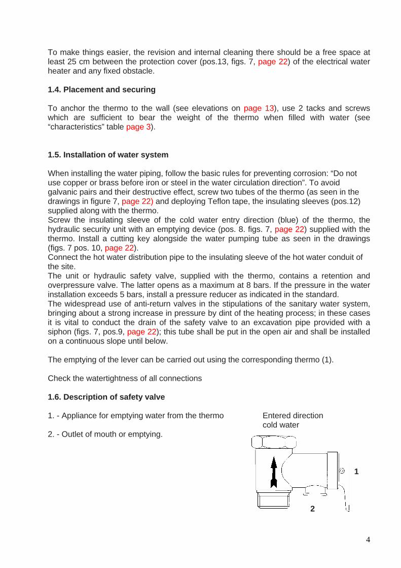
To make things easier, the revision and internal cleaning there should be a free space at least 25 cm between the protection cover (pos.13, figs. 7, page 22) of the electrical water heater and any fixed obstacle. 1.4. Placement and securing To anchor the thermo to the wall (see elevations on page 13), use 2 tacks and screws which are sufficient to bear the weight of the thermo when filled with water (see “characteristics” table page 3). 1.5. Installation of water system When installing the water piping, follow the basic rules for preventing corrosion: “Do not use copper or brass before iron or steel in the water circulation direction”. To avoid galvanic pairs and their destructive effect, screw two tubes of the thermo (as seen in the drawings in figure 7, page 22) and deploying Teflon tape, the insulating sleeves (pos.12) supplied along with the thermo. Screw the insulating sleeve of the cold water entry direction (blue) of the thermo, the hydraulic security unit with an emptying device (pos. 8. figs. 7, page 22) supplied with the thermo. Install a cutting key alongside the water pumping tube as seen in the drawings (figs. 7 pos. 10, page 22). Connect the hot water distribution pipe to the insulating sleeve of the hot water conduit of the site. The unit or hydraulic safety valve, supplied with the thermo, contains a retention and overpressure valve. The latter opens as a maximum at 8 bars. If the pressure in the water installation exceeds 5 bars, install a pressure reducer as indicated in the standard. The widespread use of anti-return valves in the stipulations of the sanitary water system, bringing about a strong increase in pressure by dint of the heating process; in these cases it is vital to conduct the drain of the safety valve to an excavation pipe provided with a siphon (figs. 7, pos.9, page 22); this tube shall be put in the open air and shall be installed on a continuous slope until below. The emptying of the lever can be carried out using the corresponding thermo (1). Check the watertightness of all connections 1.6. Description of safety valve 1. - Appliance for emptying water from the thermo Entered direction
cold water 2. - Outlet of mouth or emptying. 1
2
4
1.7. Electrical installation Ensure that the electrical voltage available is 230 / 50 Hz The connection cable of the thermo has a Schuko type pin with earth outlet side contacts. Make sure that the current outlet is a suitable connection base for the pin and that the three conductors (one being earth) up to the connection base have enough section for the power to be consumed Make sure that the electrical installation has the regulatory differential switch (fig.6, page 14). The power cable is of the type H05 V V F 3 x 1 mm white 1.8. Coming on line Fill the thermo with water, opening the cold water stopcock and the hot water taps. When water comes out of the latter, close them, starting with the lowest (bidet) and finishing with the highest (shower). In this way the air shall be eliminated from the thermo and the piping. Connect the thermo connecting the pin. The pilot lamp (pos.7, figs. 7, page 22) on means that the water is being heated up; if off, this means that all the hot water is at the temperature selected in the regulation thermostat (pos.11, figs 7, pages 22). 1.9. Conservation It is vital that the Technical Assistance Service (SAT) annually revises its thermo to eliminate the lime deposited in the heating element (pos.5, figs. 7, page 22) and check the status of the magnesium anode (pos.5, figs. 7, page 22). If the water in your area is very hard and corrosive you should ask for more frequent revisions. If the magnesium anode of your thermo is very worn, the SAT shall replace it with a new one. Don’t forget to regularly operate the pressure valve so as to prevent it from blocking using lever no. 1, a safety valve device for emptying water from the thermo (page 4). To clean the exterior of the thermo you should use a damp cloth with soapy water. Do not use abrasive products or those which contain dissolvents (for example, alcohol). For safety reasons, COINTRA GODESIA, S.A is not responsible for using any other elements which are not of origin and installed by your Technical Assistance Service. 1.10. Thermostat adjustable from the exterior The exterior temperature regulating thermostat is situated inside the thermo To increase the temperature of the accumulated water, turn the control clockwise and anticlockwise to reduce it.
5
5. SERVICIO DE ASISTENCIA TÉCNICA
SERVICIO DE ASISTENCIA TÉCNICA DEL FABRICANTE
Más de 120 puntos en toda España. Estamos a su disposición en el teléfono:
902 40 20 10
NADIE MEJOR QUE COINTRA CONOCE SU TERMO
Asegure la vida y buen funcionamiento de su aparato. COINTRA le ofrece la seriedad y garantía que sólo puede dar el Servicio
Técnico Oficial del Fabricante.
Solicite información en su teléfono amigo 902 40 20 10
6
7