Embed Size (px)
Citation preview
Product advantagesMobile crane LTM 1100/2
Max. lifting capacity: 100 tMax. height under hook: 72 m with biparted swing-away jibMax. radius: 64 m with biparted swing-away jib
Performance profile of the LTM 1100/2 at a glance.P Rapid-cycle telescoping system ìTelematikî with
patented internal interlocking system, fully automaticor manually controlled telescoping is practicable
P 10.8 m ñ 19 m long biparted swing-away jib, mountableat 0°, 20° and 40°, hydraulic erection aid
P LICCON, the most modern crane computer system world-wide with comprehensive informative, monitoring andcontrol functions
P Diesel engine, slewing rim, slewing gear and winchesare self-manufactured and quality-checked components
P The LTM 1100/2 is manufactured by Liebherr within the scope of a quality assurance system acc. toDIN ISO 9001
P Operative weight 60 t, incl. 15 t counterweight, drive10 x 6, tyres 14.00 R 25
P Powerful, energy-saving and emission-optimizedLiebherr Diesel engines, carrier engine of 400 kW output(EURO 3) and with fully electronic engine management,crane engine of 149 kW output.
P Ultramodern data bus technique with CAN bus and3 Liebherr system busses
P Travel control and outrigger actuation from the cranecabin, a standard feature
P Comfortable electric/electronic crane control withintegrated LICCON system
P Compact, 6-section telescopic boom of 11.5 m ñ 52 m length, with oviform boom profile of high lateral stability
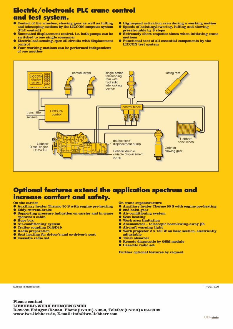
Electric/electronic PLC crane controland test system.P Control of the winches, slewing gear as well as luffing
and telescoping motions by the LICCON computer system(PLC control)
P Summated displacement control, i.e. both pumps can beswitched to one single consumer
P Electric load sensing, open oil circuits with displacementcontrol
P Four working motions can be performed independentof one another
P High-speed activation even during a working motionP Speeds of hoisting/lowering, luffing and slewing
preselectable by 6 stepsP Extremely short response times when initiating crane
motionsP Functional test of all essential components by the
LICCON test system
Optional features extend the application spectrum andincrease comfort and safety.On the carrierP Auxiliary heater Thermo 90 S with engine pre-heatingP Eddy-current-brakeP Supporting pressure indication on carrier and in crane
operator's cabinP Rope boxP Air-conditioning systemP Trailer coupling D12/D19P Radio preparationP Seat heating for driver's and co-driver's seatP Cassette radio set
On crane superstructureP Auxiliary heater Thermo 90 S with engine pre-heatingP 2nd hoist gearP Air-conditioning systemP Seat heatingP Work area limitationP Anemometer ñ telescopic boom/swing-away jibP Aircraft warning lightP Work projector 2 x 150 W on base section, electrically
adjustableP Twist absorberP Remote diagnostic by GSM moduleP Cassette radio set
Further optional features by request.
The better crane.
Please contactLIEBHERR-WERK EHINGEN GMBH, Postfach 1361, D-89582 EhingenS (0 73 91) 5 02-0, Fax (0 73 91) 5 02-3 99www.lwe.liebherr.de, E-Mail: [email protected]
Subject to modification. TP 297. 3.00
LICCON-displayscreen
control levers single-actiontelescopingram withhydraulicinterlockingdevice
luffing ram
transmitter,
sensors
LICCON-control
control block
double fixeddisplacement pump
Liebherrslewing gear
Liebherrhoist winch
Liebherr doublevariable displacementpump
LiebherrDiesel engine
D 924 TI-E

PN LTM 1100/2 DEF 07.04.2000 18:39 Uhr Seite 2
Probedruck
C M Y CM MY CY CMY K
2 3 4
The LTM 1100/2 – more benefitthrough advanced technology.
Compact, manoeuvrable andweight-optimized.� Overall length 13.6 m, length of carrier 11.2 m� Large front and rear overhang angles of up to 25°� Small turning radius of 10.05 m with all-wheel steering� Just 3.84 m tail radius of counterweight� 60 t total weight, incl. 15 t counterweight, drive
10 x 6, tyre size 14, 8.8 t load hook (axle load 5 x 12 t)� 2 optional tyre sizes
14.00 R 25 – vehicle width 2.75 m16.00 R 25 – vehicle width 2.75 m
Variable drive and steeringconcept.� Drive 10 x 6, axles 1, 4 and 5 are driven� Drive 10 x 8 (optional), axles 1, 2, 4 and 5 are driven,
for road travel 1st, 4th and 5th axle are driven, 2nd axleactivatable for off-road travel
� Axles 1, 2, 4 and 5 are steered, the 4th and 5th axle arealso steerable independent of axles 1 and 2 (for crabsteering/diagonal displacement, the 3rd axle is raisedhydraulically for that purpose); all steering modes arealso controllable from the crane cabin.
Setting crane on outriggers –quick, convenient and safe� Variable supporting basis
Outriggers retractedSupporting basis 5 m x 7.2 mSupporting basis 7 m x 7.2 m
� Fix-mounted supporting pads, protected by splashguards
� Supporting ram travel up to 700 mm� Levelling control for outrigger system, fully automatic
levelling of the crane during the supporting procedureby “pushbutton”
� 2 x 8° lateral inclination of carrier and cranesuperstructure
� The control panels on either side of the carrier, withmembrane keyboard and electronic inclinometer as wellas keyboard for ENGINE/START/STOP and enginecontrol, are illuminated and lockable
� Operation of the outrigger system can equally beperformed from the crane cabin (standard)
� Operation of the outrigger system in accordance withthe rules for the prevention of accidents
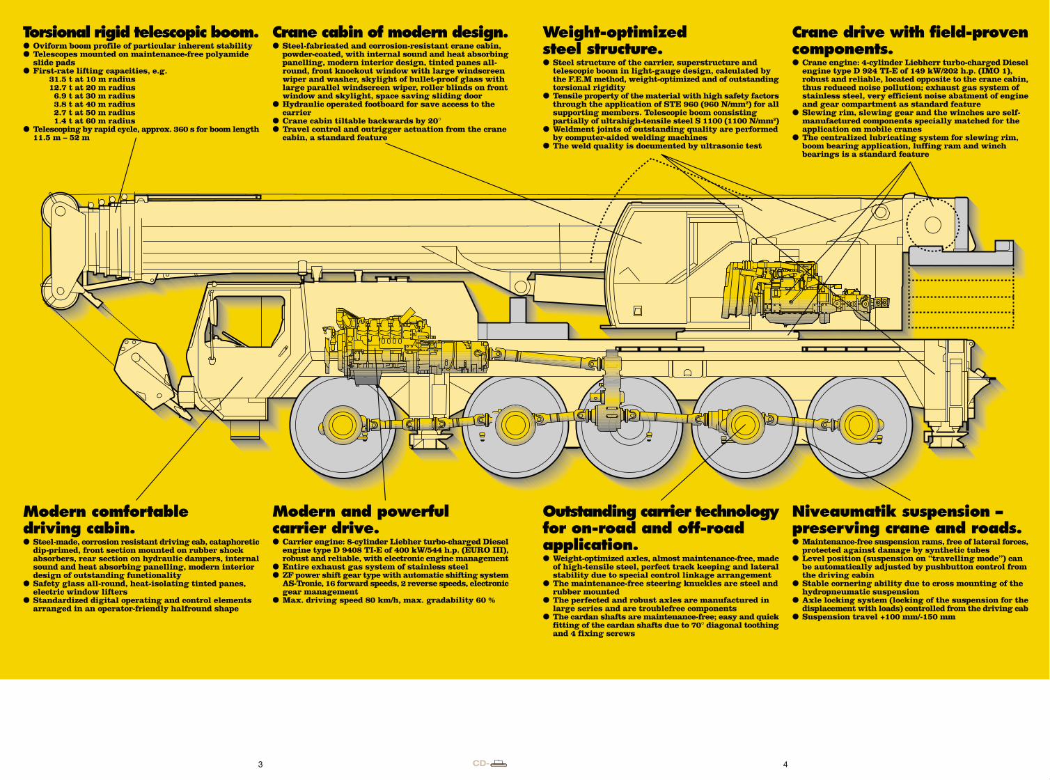
Torsional rigid telescopic boom.� Oviform boom profile of particular inherent stability� Telescopes mounted on maintenance-free polyamide
slide pads� First-rate lifting capacities, e.g.
31.5 t at 10 m radius12.7 t at 20 m radius 6.9 t at 30 m radius 3.8 t at 40 m radius 2.7 t at 50 m radius 1.4 t at 60 m radius
� Telescoping by rapid cycle, approx. 360 s for boom length11.5 m – 52 m
Modern and powerfulcarrier drive.� Carrier engine: 8-cylinder Liebher turbo-charged Diesel
engine type D 9408 TI-E of 400 kW/544 h.p. (EURO III),robust and reliable, with electronic engine management
� Entire exhaust gas system of stainless steel� ZF power shift gear type with automatic shifting system
AS-Tronic, 16 forward speeds, 2 reverse speeds, electronicgear management
� Max. driving speed 80 km/h, max. gradability 60 %
Crane cabin of modern design.� Steel-fabricated and corrosion-resistant crane cabin,
powder-coated, with internal sound and heat absorbingpanelling, modern interior design, tinted panes all-round, front knockout window with large windscreenwiper and washer, skylight of bullet-proof glass with large parallel windscreen wiper, roller blinds on frontwindow and skylight, space saving sliding door
� Hydraulic operated footboard for save access to the carrier
� Crane cabin tiltable backwards by 20°� Travel control and outrigger actuation from the crane
cabin, a standard feature
Crane drive with field-provencomponents.� Crane engine: 4-cylinder Liebherr turbo-charged Diesel
engine type D 924 TI-E of 149 kW/202 h.p. (IMO 1),robust and reliable, located opposite to the crane cabin,thus reduced noise pollution; exhaust gas system ofstainless steel, very efficient noise abatment of engineand gear compartment as standard feature
� Slewing rim, slewing gear and the winches are self-manufactured components specially matched for theapplication on mobile cranes
� The centralized lubricating system for slewing rim,boom bearing application, luffing ram and winchbearings is a standard feature
Modern comfortabledriving cabin.� Steel-made, corrosion resistant driving cab, cataphoretic
dip-primed, front section mounted on rubber shockabsorbers, rear section on hydraulic dampers, internalsound and heat absorbing panelling, modern interiordesign of outstanding functionality
� Safety glass all-round, heat-isolating tinted panes,electric window lifters
� Standardized digital operating and control elementsarranged in an operator-friendly halfround shape
Outstanding carrier technologyfor on-road and off-roadapplication.� Weight-optimized axles, almost maintenance-free, made
of high-tensile steel, perfect track keeping and lateralstability due to special control linkage arrangement
� The maintenance-free steering knuckles are steel andrubber mounted
� The perfected and robust axles are manufactured inlarge series and are troublefree components
� The cardan shafts are maintenance-free; easy and quickfitting of the cardan shafts due to 70° diagonal toothingand 4 fixing screws
Niveaumatik suspension –preserving crane and roads.� Maintenance-free suspension rams, free of lateral forces,
protected against damage by synthetic tubes� Level position (suspension on “travelling mode”) can
be automatically adjusted by pushbutton control fromthe driving cabin
� Stable cornering ability due to cross mounting of thehydropneumatic suspension
� Axle locking system (locking of the suspension for thedisplacement with loads) controlled from the driving cab
� Suspension travel +100 mm/-150 mm
Weight-optimizedsteel structure.� Steel structure of the carrier, superstructure and
telescopic boom in light-gauge design, calculated bythe F.E.M method, weight-optimized and of outstandingtorsional rigidity
� Tensile property of the material with high safety factorsthrough the application of STE 960 (960 N/mm2) for allsupporting members. Telescopic boom consistingpartially of ultrahigh-tensile steel S 1100 (1100 N/mm2)
� Weldment joints of outstanding quality are performedby computer-aided welding machines
� The weld quality is documented by ultrasonic test
13.66 t
25°
3.99
25°
5.5 t
7.2
16.00 R 25 12 t 12 t 12 t 12 t 12 t11.261.9
7
2.75 5
R = 8.74
R = 10.05
R = 10.7R = 11.3 R
= 5.2
7.2
700
R = 3.83
0.55 m
3,5 t
2 3 4
The LTM 1100/2 – more benefitthrough advanced technology.
Compact, manoeuvrable andweight-optimized.� Overall length 13.6 m, length of carrier 11.2 m� Large front and rear overhang angles of up to 25°� Small turning radius of 10.05 m with all-wheel steering� Just 3.84 m tail radius of counterweight� 60 t total weight, incl. 15 t counterweight, drive
10 x 6, tyre size 14, 8.8 t load hook (axle load 5 x 12 t)� 2 optional tyre sizes
14.00 R 25 – vehicle width 2.75 m16.00 R 25 – vehicle width 2.75 m
Variable drive and steeringconcept.� Drive 10 x 6, axles 1, 4 and 5 are driven� Drive 10 x 8 (optional), axles 1, 2, 4 and 5 are driven,
for road travel 1st, 4th and 5th axle are driven, 2nd axleactivatable for off-road travel
� Axles 1, 2, 4 and 5 are steered, the 4th and 5th axle arealso steerable independent of axles 1 and 2 (for crabsteering/diagonal displacement, the 3rd axle is raisedhydraulically for that purpose); all steering modes arealso controllable from the crane cabin.
Setting crane on outriggers –quick, convenient and safe� Variable supporting basis
Outriggers retractedSupporting basis 5 m x 7.2 mSupporting basis 7 m x 7.2 m
� Fix-mounted supporting pads, protected by splashguards
� Supporting ram travel up to 700 mm� Levelling control for outrigger system, fully automatic
levelling of the crane during the supporting procedureby “pushbutton”
� 2 x 8° lateral inclination of carrier and cranesuperstructure
� The control panels on either side of the carrier, withmembrane keyboard and electronic inclinometer as wellas keyboard for ENGINE/START/STOP and enginecontrol, are illuminated and lockable
� Operation of the outrigger system can equally beperformed from the crane cabin (standard)
� Operation of the outrigger system in accordance withthe rules for the prevention of accidents
Torsional rigid telescopic boom.� Oviform boom profile of particular inherent stability� Telescopes mounted on maintenance-free polyamide
slide pads� First-rate lifting capacities, e.g.
31.5 t at 10 m radius12.7 t at 20 m radius 6.9 t at 30 m radius 3.8 t at 40 m radius 2.7 t at 50 m radius 1.4 t at 60 m radius
� Telescoping by rapid cycle, approx. 360 s for boom length11.5 m – 52 m
Modern and powerfulcarrier drive.� Carrier engine: 8-cylinder Liebher turbo-charged Diesel
engine type D 9408 TI-E of 400 kW/544 h.p. (EURO III),robust and reliable, with electronic engine management
� Entire exhaust gas system of stainless steel� ZF power shift gear type with automatic shifting system
AS-Tronic, 16 forward speeds, 2 reverse speeds, electronicgear management
� Max. driving speed 80 km/h, max. gradability 60 %
Crane cabin of modern design.� Steel-fabricated and corrosion-resistant crane cabin,
powder-coated, with internal sound and heat absorbingpanelling, modern interior design, tinted panes all-round, front knockout window with large windscreenwiper and washer, skylight of bullet-proof glass with large parallel windscreen wiper, roller blinds on frontwindow and skylight, space saving sliding door
� Hydraulic operated footboard for save access to the carrier
� Crane cabin tiltable backwards by 20°� Travel control and outrigger actuation from the crane
cabin, a standard feature
Crane drive with field-provencomponents.� Crane engine: 4-cylinder Liebherr turbo-charged Diesel
engine type D 924 TI-E of 149 kW/202 h.p. (IMO 1),robust and reliable, located opposite to the crane cabin,thus reduced noise pollution; exhaust gas system ofstainless steel, very efficient noise abatment of engineand gear compartment as standard feature
� Slewing rim, slewing gear and the winches are self-manufactured components specially matched for theapplication on mobile cranes
� The centralized lubricating system for slewing rim,boom bearing application, luffing ram and winchbearings is a standard feature
Modern comfortabledriving cabin.� Steel-made, corrosion resistant driving cab, cataphoretic
dip-primed, front section mounted on rubber shockabsorbers, rear section on hydraulic dampers, internalsound and heat absorbing panelling, modern interiordesign of outstanding functionality
� Safety glass all-round, heat-isolating tinted panes,electric window lifters
� Standardized digital operating and control elementsarranged in an operator-friendly halfround shape
Outstanding carrier technologyfor on-road and off-roadapplication.� Weight-optimized axles, almost maintenance-free, made
of high-tensile steel, perfect track keeping and lateralstability due to special control linkage arrangement
� The maintenance-free steering knuckles are steel andrubber mounted
� The perfected and robust axles are manufactured inlarge series and are troublefree components
� The cardan shafts are maintenance-free; easy and quickfitting of the cardan shafts due to 70° diagonal toothingand 4 fixing screws
Niveaumatik suspension –preserving crane and roads.� Maintenance-free suspension rams, free of lateral forces,
protected against damage by synthetic tubes� Level position (suspension on “travelling mode”) can
be automatically adjusted by pushbutton control fromthe driving cabin
� Stable cornering ability due to cross mounting of thehydropneumatic suspension
� Axle locking system (locking of the suspension for thedisplacement with loads) controlled from the driving cab
� Suspension travel +100 mm/-150 mm
Weight-optimizedsteel structure.� Steel structure of the carrier, superstructure and
telescopic boom in light-gauge design, calculated bythe F.E.M method, weight-optimized and of outstandingtorsional rigidity
� Tensile property of the material with high safety factorsthrough the application of STE 960 (960 N/mm2) for allsupporting members. Telescopic boom consistingpartially of ultrahigh-tensile steel S 1100 (1100 N/mm2)
� Weldment joints of outstanding quality are performedby computer-aided welding machines
� The weld quality is documented by ultrasonic test
13.66 t
25°
3.99
25°
5.5 t
7.2
16.00 R 25 12 t 12 t 12 t 12 t 12 t11.261.9
7
2.75 5
R = 8.74
R = 10.05
R = 10.7R = 11.3 R
= 5.2
7.2
700
R = 3.83
0.55 m
3,5 t
5 76
16
17
18
15
1413
7
19 19
8
4a
3a
5
20
21
6
1
2
2a
1a
11
4
3
8
9
10
LSB-Bus 1
CAN-Bus
LSB-Bus 3
LSB-Bus 2
CAN-Bus
12
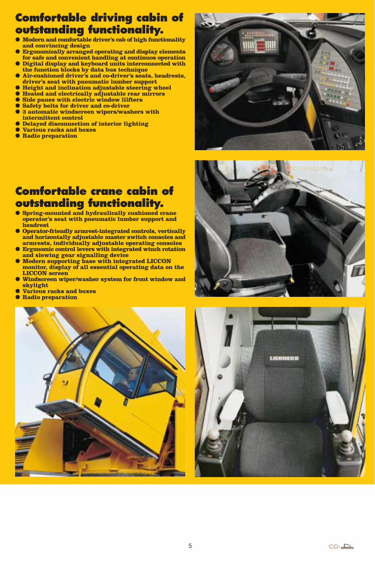
Comfortable driving cabin ofoutstanding functionality.P Modern and comfortable driver’s cab of high functionality
and convincing designP Ergonomically arranged operating and display elements
for safe and convenient handling at continuos operationP Digital display and keyboard units interconnected with
the function blocks by data bus techniqueP Air-cushioned driver’s and co-driver’s seats, headrests,
driver’s seat with pneumatic lumber supportP Height and inclination adjustable steering wheelP Heated and electrically adjustable rear mirrorsP Side panes with electric window lilftersP Safety belts for driver and co-driverP 3 automatic windscreen wipers/washers with
intermittent controlP Delayed disconnection of interior lightingP Various racks and boxesP Radio preparation
Comfortable crane cabin ofoutstanding functionality.P Spring-mounted and hydraulically cushioned crane
operator’s seat with pneumatic lumber support andheadrest
P Operator-friendly armrest-integrated controls, verticallyand horizontally adjustable master switch consoles andarmrests, individually adjustable operating consoles
P Ergonomic control levers with integrated winch rotationand slewing gear signalling device
P Modern supporting base with integrated LICCONmonitor, display of all essential operating data on theLICCON screen
P Windscreen wiper/washer system for front window andskylight
P Various racks and boxesP Radio preparation
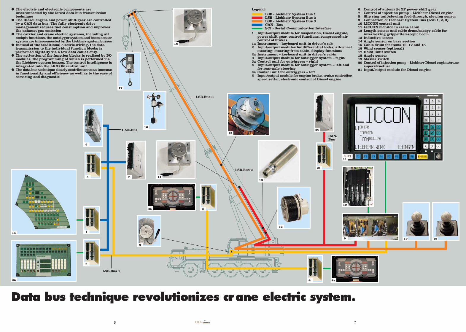
P The electric and electronic components areinterconnected by the latest data bus transmissiontechnique
P The Diesel engine and power shift gear are controlledby a CAN data bus. The fully electronic drivemanagement reduces fuel consumption and improvesthe exhaust gas emission
P The carrier and crane electric systems, including all cockpit functions, the outrigger system and boom sensorsystem are interconnected by the Liebherr system busses
P Instead of the traditional electric wiring, the data transmission to the individual function blocks isperformed digitally via a few data cables only.
P The activation of the function blocks is realized by I/Omodules, the programming of which is performed viathe Liebherr system busses. The control intelligence isintegrated into the LICCON central unit
P The data bus technique clearly contributes to an increasein functionality and efficiency as well as to the ease ofservicing and diagnostic
Data bus technique revolutionizes crane electric system.
Legend:LSB - Liebherr System Bus 1LSB - Liebherr System Bus 2LSB - Liebherr System Bus 3CAN - BusSCI - Serial Communication Interface
1 Input/output module for suspension, Diesel engine, power shift gear, control functions, compressed-air control of brakes
1a Instrument – keyboard unit in driver’s cab2 Input/output modules for differential locks, all-wheel
steering, steering from cabin, display functions2a Instrument – keyboard unit in driver’s cabin3 Input/output module for outrigger system – right3a Control unit for outriggers – right4 Input/output module for outrigger system – left and
for rear-axle steering4a Control unit for outriggers – left5 Input/output module for engine brake, cruise controller,
speed setter, electronic control of Diesel engine
6 Control of automatic ZF power shift gear7 Control of injection pump – Liebherr Diesel engine8 Slip ring unit/slewing feed-through, slewing sensor9 Connection of Liebherr System Bus (LSB 1, 2, 3)10 LICCON central unit11 LICCON monitor in crane cabin12 Length sensor and cable drum/energy cable for
interlocking gripper/telescopic boom13 Inductive sensor14 Angle sensor on base section15 Cable drum for items 16, 17 and 1816 Wind sensor (optional)17 Hoist limit switch18 Angle sensor19 Master switch20 Control of injection pump – Liebherr Diesel engine/crane
superstructure21 Input/output module for Diesel engine
5 76
16
17
18
15
1413
7
19 19
8
4a
3a
5
20
21
6
1
2
2a
1a
11
4
3
8
9
10
LSB-Bus 1
CAN-Bus
LSB-Bus 3
LSB-Bus 2
CAN-Bus
12
Comfortable driving cabin ofoutstanding functionality.P Modern and comfortable driver’s cab of high functionality
and convincing designP Ergonomically arranged operating and display elements
for safe and convenient handling at continuos operationP Digital display and keyboard units interconnected with
the function blocks by data bus techniqueP Air-cushioned driver’s and co-driver’s seats, headrests,
driver’s seat with pneumatic lumber supportP Height and inclination adjustable steering wheelP Heated and electrically adjustable rear mirrorsP Side panes with electric window lilftersP Safety belts for driver and co-driverP 3 automatic windscreen wipers/washers with
intermittent controlP Delayed disconnection of interior lightingP Various racks and boxesP Radio preparation
Comfortable crane cabin ofoutstanding functionality.P Spring-mounted and hydraulically cushioned crane
operator’s seat with pneumatic lumber support andheadrest
P Operator-friendly armrest-integrated controls, verticallyand horizontally adjustable master switch consoles andarmrests, individually adjustable operating consoles
P Ergonomic control levers with integrated winch rotationand slewing gear signalling device
P Modern supporting base with integrated LICCONmonitor, display of all essential operating data on theLICCON screen
P Windscreen wiper/washer system for front window andskylight
P Various racks and boxesP Radio preparation
P The electric and electronic components areinterconnected by the latest data bus transmissiontechnique
P The Diesel engine and power shift gear are controlledby a CAN data bus. The fully electronic drivemanagement reduces fuel consumption and improvesthe exhaust gas emission
P The carrier and crane electric systems, including all cockpit functions, the outrigger system and boom sensorsystem are interconnected by the Liebherr system busses
P Instead of the traditional electric wiring, the data transmission to the individual function blocks isperformed digitally via a few data cables only.
P The activation of the function blocks is realized by I/Omodules, the programming of which is performed viathe Liebherr system busses. The control intelligence isintegrated into the LICCON central unit
P The data bus technique clearly contributes to an increasein functionality and efficiency as well as to the ease ofservicing and diagnostic
Data bus technique revolutionizes crane electric system.
Legend:LSB - Liebherr System Bus 1LSB - Liebherr System Bus 2LSB - Liebherr System Bus 3CAN - BusSCI - Serial Communication Interface
1 Input/output module for suspension, Diesel engine, power shift gear, control functions, compressed-air control of brakes
1a Instrument – keyboard unit in driver’s cab2 Input/output modules for differential locks, all-wheel
steering, steering from cabin, display functions2a Instrument – keyboard unit in driver’s cabin3 Input/output module for outrigger system – right3a Control unit for outriggers – right4 Input/output module for outrigger system – left and
for rear-axle steering4a Control unit for outriggers – left5 Input/output module for engine brake, cruise controller,
speed setter, electronic control of Diesel engine
6 Control of automatic ZF power shift gear7 Control of injection pump – Liebherr Diesel engine8 Slip ring unit/slewing feed-through, slewing sensor9 Connection of Liebherr System Bus (LSB 1, 2, 3)10 LICCON central unit11 LICCON monitor in crane cabin12 Length sensor and cable drum/energy cable for
interlocking gripper/telescopic boom13 Inductive sensor14 Angle sensor on base section15 Cable drum for items 16, 17 and 1816 Wind sensor (optional)17 Hoist limit switch18 Angle sensor19 Master switch20 Control of injection pump – Liebherr Diesel engine/crane
superstructure21 Input/output module for Diesel engine
8 9
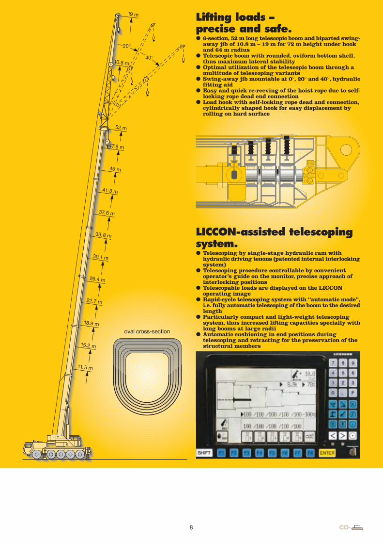
Lifting loads –precise and safe.P 6-section, 52 m long telescopic boom and biparted swing-
away jib of 10.8 m – 19 m for 72 m height under hookand 64 m radius
P Telescopic boom with rounded, oviform bottom shell,thus maximum lateral stability
P Optimal utilization of the telescopic boom through amultitude of telescoping variants
P Swing-away jib mountable at 0°, 20° and 40°, hydraulicfitting aid
P Easy and quick re-reeving of the hoist rope due to self-locking rope dead end connection
P Load hook with self-locking rope dead and connection,cylindrically shaped hook for easy displacement byrolling on hard surface
oval cross-section
LICCON-assisted telescopingsystem.P Telescoping by single-stage hydraulic ram with
hydraulic driving tenons (patented internal interlockingsystem)
P Telescoping procedure controllable by convenient operator’s guide on the monitor, precise approach of interlocking positions
P Telescopable loads are displayed on the LICCONoperating image
P Rapid-cycle telescoping system with “automatic mode”,i.e. fully automatic telescoping of the boom to the desiredlength
P Particularly compact and light-weight telescopingsystem, thus increased lifting capacities specially withlong booms at large radii
P Automatic cushioning in end positions duringtelescoping and retracting for the preservation of the structural members
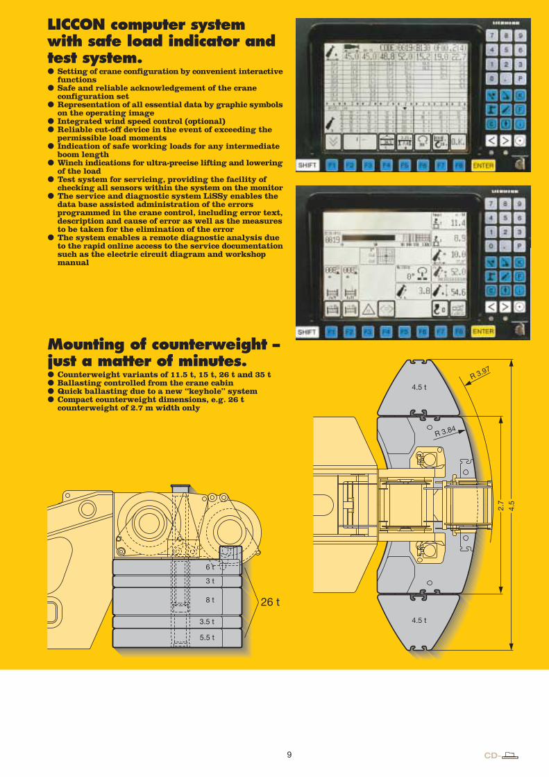
LICCON computer systemwith safe load indicator andtest system.P Setting of crane configuration by convenient interactive
functionsP Safe and reliable acknowledgement of the crane
configuration setP Representation of all essential data by graphic symbols
on the operating imageP Integrated wind speed control (optional)P Reliable cut-off device in the event of exceeding the
permissible load momentsP Indication of safe working loads for any intermediate
boom lengthP Winch indications for ultra-precise lifting and lowering
of the loadP Test system for servicing, providing the facility of
checking all sensors within the system on the monitorP The service and diagnostic system LiSSy enables the
data base assisted administration of the errorsprogrammed in the crane control, including error text,description and cause of error as well as the measuresto be taken for the elimination of the error
P The system enables a remote diagnostic analysis dueto the rapid online access to the service documentationsuch as the electric circuit diagram and workshopmanual
Mounting of counterweight –just a matter of minutes.P Counterweight variants of 11.5 t, 15 t, 26 t and 35 tP Ballasting controlled from the crane cabinP Quick ballasting due to a new “keyhole” systemP Compact counterweight dimensions, e.g. 26 t
counterweight of 2.7 m width only
11.5 m
15.2 m
18.9 m
22.7 m
26.4 m
45 m
41.3 m
37.6 m
33.8 m
30.1 m
52 m
47.8 m
19 m
10.8 m
20°
40°
2.7
4.5
R 3.84
R 3.97
6 t
8 t
3.5 t
3 t
5.5 t
26 t
4.5 t
4.5 t
8 9
Lifting loads –precise and safe.P 6-section, 52 m long telescopic boom and biparted swing-
away jib of 10.8 m – 19 m for 72 m height under hookand 64 m radius
P Telescopic boom with rounded, oviform bottom shell,thus maximum lateral stability
P Optimal utilization of the telescopic boom through amultitude of telescoping variants
P Swing-away jib mountable at 0°, 20° and 40°, hydraulicfitting aid
P Easy and quick re-reeving of the hoist rope due to self-locking rope dead end connection
P Load hook with self-locking rope dead and connection,cylindrically shaped hook for easy displacement byrolling on hard surface
oval cross-section
LICCON-assisted telescopingsystem.P Telescoping by single-stage hydraulic ram with
hydraulic driving tenons (patented internal interlockingsystem)
P Telescoping procedure controllable by convenient operator’s guide on the monitor, precise approach of interlocking positions
P Telescopable loads are displayed on the LICCONoperating image
P Rapid-cycle telescoping system with “automatic mode”,i.e. fully automatic telescoping of the boom to the desiredlength
P Particularly compact and light-weight telescopingsystem, thus increased lifting capacities specially withlong booms at large radii
P Automatic cushioning in end positions duringtelescoping and retracting for the preservation of the structural members
LICCON computer systemwith safe load indicator andtest system.P Setting of crane configuration by convenient interactive
functionsP Safe and reliable acknowledgement of the crane
configuration setP Representation of all essential data by graphic symbols
on the operating imageP Integrated wind speed control (optional)P Reliable cut-off device in the event of exceeding the
permissible load momentsP Indication of safe working loads for any intermediate
boom lengthP Winch indications for ultra-precise lifting and lowering
of the loadP Test system for servicing, providing the facility of
checking all sensors within the system on the monitorP The service and diagnostic system LiSSy enables the
data base assisted administration of the errorsprogrammed in the crane control, including error text,description and cause of error as well as the measuresto be taken for the elimination of the error
P The system enables a remote diagnostic analysis dueto the rapid online access to the service documentationsuch as the electric circuit diagram and workshopmanual
Mounting of counterweight –just a matter of minutes.P Counterweight variants of 11.5 t, 15 t, 26 t and 35 tP Ballasting controlled from the crane cabinP Quick ballasting due to a new “keyhole” systemP Compact counterweight dimensions, e.g. 26 t
counterweight of 2.7 m width only
11.5 m
15.2 m
18.9 m
22.7 m
26.4 m
45 m
41.3 m
37.6 m
33.8 m
30.1 m
52 m
47.8 m
19 m
10.8 m
20°
40°
2.7
4.5
R 3.84
R 3.97
6 t
8 t
3.5 t
3 t
5.5 t
26 t
4.5 t
4.5 t
Product advantagesMobile crane LTM 1100/2
Max. lifting capacity: 100 tMax. height under hook: 72 m with biparted swing-away jibMax. radius: 64 m with biparted swing-away jib
Performance profile of the LTM 1100/2 at a glance.P Rapid-cycle telescoping system “Telematik” with
patented internal interlocking system, fully automaticor manually controlled telescoping is practicable
P 10.8 m – 19 m long biparted swing-away jib, mountableat 0°, 20° and 40°, hydraulic erection aid
P LICCON, the most modern crane computer system world-wide with comprehensive informative, monitoring andcontrol functions
P Diesel engine, slewing rim, slewing gear and winchesare self-manufactured and quality-checked components
P The LTM 1100/2 is manufactured by Liebherr within the scope of a quality assurance system acc. toDIN ISO 9001
P Operative weight 60 t, incl. 15 t counterweight, drive10 x 6, tyres 14.00 R 25
P Powerful, energy-saving and emission-optimizedLiebherr Diesel engines, carrier engine of 370 kW output(EURO 3) and with fully electronic engine management,crane engine of 149 kW output (IMO 1).
P Ultramodern data bus technique with CAN bus and3 Liebherr system busses
P Travel control and outrigger actuation from the cranecabin, a standard feature
P Comfortable electric/electronic crane control withintegrated LICCON system
P Compact, 6-section telescopic boom of 11.5 m – 52 m length, with oviform boom profile of high lateral stability
Electric/electronic PLC crane controland test system.P Control of the winches, slewing gear as well as luffing
and telescoping motions by the LICCON computer system(PLC control)
P Summated displacement control, i.e. both pumps can beswitched to one single consumer
P Electric load sensing, open oil circuits with displacementcontrol
P Four working motions can be performed independentof one another
P High-speed activation even during a working motionP Speeds of hoisting/lowering, luffing and slewing
preselectable by 6 stepsP Extremely short response times when initiating crane
motionsP Functional test of all essential components by the
LICCON test system
Optional features extend the application spectrum andincrease comfort and safety.On the carrierP Auxiliary heater Thermo 90 S with engine pre-heatingP Eddy-current-brakeP Supporting pressure indication on carrier and in crane
operator’s cabinP Rope boxP Air-conditioning systemP Trailer coupling D12/D19P Radio preparationP Seat heating for driver’s and co-driver’s seatP Cassette radio set
On crane superstructureP Auxiliary heater Thermo 90 S with engine pre-heatingP 2nd hoist gearP Air-conditioning systemP Seat heatingP Work area limitationP Anemometer – telescopic boom/swing-away jibP Aircraft warning lightP Work projector 2 x 150 W on base section, electrically
adjustableP Twist absorberP Remote diagnostic by GSM moduleP Cassette radio set
Further optional features by request.
The better crane.
Subject to modification. TP 297. 3.00
LICCON-displayscreen
control levers single-actiontelescopingram withhydraulicinterlockingdevice
luffing ram
transmitter,
sensors
LICCON-control
control block
double fixeddisplacement pump
Liebherrslewing gear
Liebherrhoist winch
Liebherr doublevariable displacementpump
LiebherrDiesel engine
D 924 TI-E
Please contactLIEBHERR-WERK EHINGEN GMBH
www.lwe.liebherr.de, E-mail: [email protected] Ehingen/Donau, Phone (07391) 5 02-0, Telefax (07391) 5 02-3399