Embed Size (px)
Citation preview

JPL Publication 86-31
Electricity from Photovoltaic Solar Cells
11 Years of Progress
',i: I •
October 1986
Project Managed by the Jet Propulsion Laboratory for the U.S. Department of Energy
(_S_-CE-1806_4) FLA_-fLA_I1; SCLAB #,BRAYE_(JJEC_. VGLUI'I_ 6:EBGINkESlb6 SCIE_iCRS A_iD_£LIABILI_¥ final Befcct (Oet EIopulsion
lat.) S_ p CSCL 10aG 3/_ 4
N87-2065 1
https://ntrs.nasa.gov/search.jsp?R=19870011218 2020-03-29T21:49:07+00:00Z
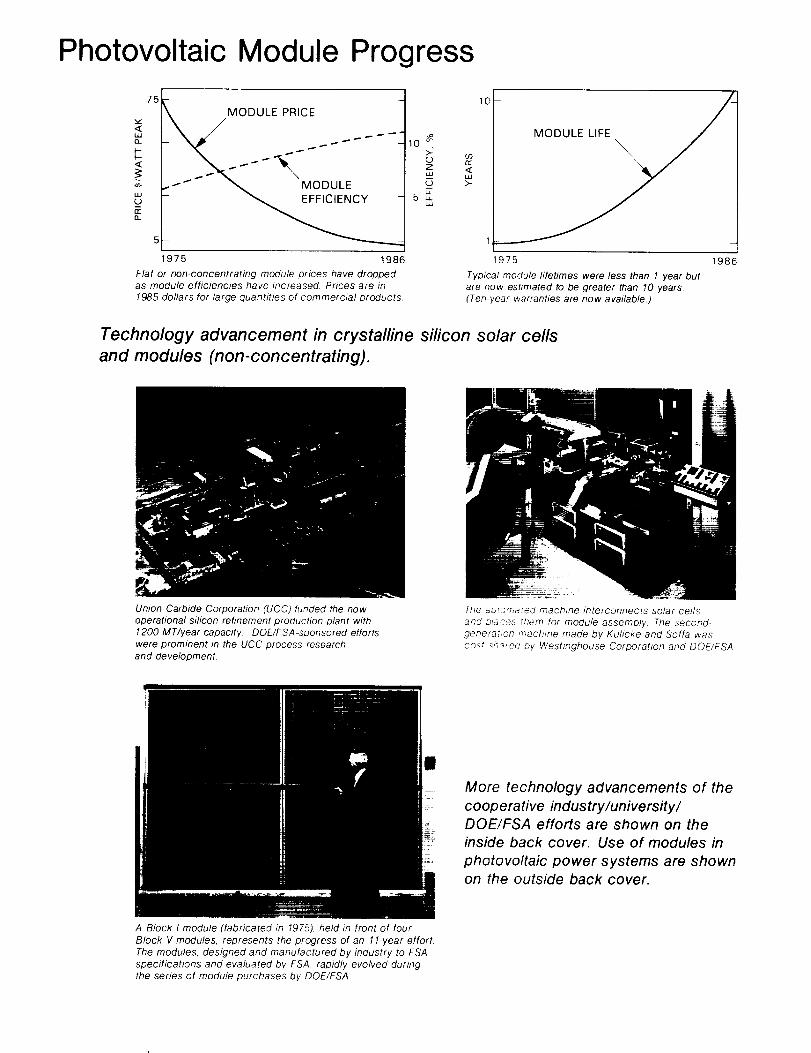
Photovoltaic Module Progress
75
F-
5
1975 1986
Flat or non-concentrating module prices have droppedas module efficiencies have increased. Prices are in
1985 dollars for large quantities of commercial products.
io
0
5_klJ
10
r_
<w
1
1-975 198,
Typical module lifetimes were less than 1 year but
are now estimated to be greater than 10 years.
(Ten-year warranties are now available.)
Technology advancement in crystalline silicon solar cells
and modules (non-concentrating).
Union Carbide Corporation (UCC) funded the now
operational silicon refinement production plant with1200 MT/year capacity. DOE/FSA-sponsored efforts
were prominent in the UCC process research
and development.
The a_,tomated machine mterconnects solar cells
and places tnem for module assembly The second-
generatmn machine made by Kuhcke and Sofia was
cos t -_ha_ed by Westinghouse Corporahon and DOE/FSA
U
More technology advancements of the
cooperative industry/university/DOE/FSA efforts are shown on theinside back cover. Use of modules in
photovottaic power systems are shownon the outside back cover.
A Block I module (fabricated in 1975), held in front of four
Block V modules, represents the progress of an 11-year effort
The modules, designed and manufactured by industry to FSA
specifications and evaluated by FSA, rapidly evolved during
the series of module purchases by DOE/FSA

5101-289
Flat-Plate
Solar Array Project
DOE/JPL-1012-125
Distribution Category UC-63b
Electricity from Photovoltaic Solar Cells
Flat-Plate Solar Array ProjectFinal Report
Volume VI: Engineering Sciences and Reliability
R.G. Ross, Jr.M.I. Smokier
11 Years of Progress
October 1986
Prepared for
U.S. Department of Energy
Through an Agreement with
National Aeronautics and Space Administration
by
Jet Propulsion Laboratory
California Institule of Technology
Pasadena, California
Project Managedby the
Jet Propulsion Laboratory
for the
U.S. Department of Energy's
National Photovoltaics Program
JPL Publication 86-31

Final Report Organization
This FSA Final Report (JPL Publication 86-31,5101-289, DOE/JPL 1012-1 25, October 1986) is composed of eightvolumes, consisting of an Executive Summary and seven technology reports:
Volume I: Executive Summary.
Volume It: Silicon Material.
Volume II1: Silicon Sheet: Wafers and Ribbons
Volume IV: High-Efficiency Solar Cells.
Volume V: Process Development.
Volume VI: Engineering Sciences and Reliability.
Volume VII: Module Encapsulation.
Volume VIII: Project Analysis and Integration.
Two supplemental reports included in the final report package are:
FSA Project. 10 Years of Progress, JPL Document 400-279, 5101-279, October 1985.
Summary of FSA Prolect Documentation: Abstracts of Pubhshed Documents, 1975 to 1986, JPL Publication 82-79(Revision 1), 5101-221, DOE/JPL-1012-76, September 1986.
Upon request, this FSA Final Report (JPL Publication 86-31 ) and the two supplemental reports {JPL Document400-279 and JPL Publication 82-79) are individually available in print from:
National Technical Information Service
U.S. Department of Commerce5285 Port Royal RoadSpringfield, VA 221 61

Abstract
The Flat-Plate Solar Array (FSA) Project, funded by the U.S. Government and managed by the Jet PropulsionLaboratory, was formed in 1975 to develop the module/array technology needed to attain widespread terrestrial useof photovoltaics by 1985. To accomplish this, the FSA Project established and managed an Industry, University, andFederal Government Team to perform the needed research and development.
This volume of the series of final reports documenting the FSA Project deals with the Project's activities directedat developing the engineering technology base required to achieve modules that meet the functional, safety andreliability requirements of large-scale terrestrial photovoltaic systems applications. These activities included: (1) devel-opment of functional, safety, and reliability requirements for such applications; ('2) development of the engineeringanalytical approaches, test techniques, and design solutions required to meet the requirements; ('3) synthesis and pro-curement of candidate designs for test and evaluation; and (4) performance of extensive testing, evaluation, and failureanalysis to define design shortfalls and, thus, areas requiring additional research and development.
During the life of the FSA Project, these activities were known by and included a variety of evolving organiza-tional titles: Design and Test, Large-Scale Procurements, Engineering, Engineering Sciences, Operations, ModulePerformance and Failure Analysis, and at the end of the Project, Reliability and Engineering Sciences.
This volume provides both a summary of the approach and technical outcome of these activities and provides acomplete Bibliography (Appendix A) of the published documentation covering the detailed accomplishments andtechnologies developed.
iii

Foreword
Throughout U.S. history, the Nation's main source of energy has changed from wood to coal to petroleum. It isinevitable that changes will continue as fossil fuels are depleted. Within a lifetime, it is expected that most US. energywill come from a variety of sources, including renewable energy sources, instead of from a single type of fuel. Morethan 30 % of the energy consumed in the United States is used for the generation of electricity. The consumption ofelectricity is increasing at a faster rate than the use of other energy forms and this trend is expected to continue.
Photovoltaics, a promising way to generate electricity, is expected to provide significant amounts of power in years tocome. It uses solar cells to generate electricity directly from sunlight, cleanly and reliably, without moving parts.Photovoltaic (PV) power systems are simple, flexible, modular, and adaplabte to many different applications in analmost infinite number of sizes and in diverse environments. Although photovoltaics is a proven technology that iscost-effective for hundreds of small applications, it is not yet cost-effective for large-scale utility use in the UnitedStates. For widespread economical use, the cost of generating power wilh Dhotovoltaics must continue to bedecreased by reducing the initial PV system cost, by increasing efficiency (reduction of land requirements), and byincreasing the operational lifetime of the PV systems.
In the early 1970s, the pressures of the increasing demand for electrical power, combined with the uncertainty offuel sources and ever-increasing prices for petroleum, led the U.S. Government to initiate a terrestrial PV research anddevelopment (R&D) project. The objective was to reduce the cost of manufacturing solar cells and modules. Thiseffort, assigned to the Jet Propulsion Laboratory, evolved from more than a decade-and-a-half of spacecraft PV power-system experience and from recommendations of a conference on Solar Photovoltaic Energy held in 1973 at CherryHill, New Jersey.
This Project, originally called the Low-Cost Solar Array Project, but later kP,own as the Flat-Plate Solar Array (FSA)Project, was based upon crystalline-silicon technology as developed for the space program. During the t960s and1970s, it had been demonstrated that photovoltaics was a dependable eqectrical power source for spacecraft. In thistime interval, solar-cell quality and performance improved while the costs decreased. However, in 1975 the costs werestill much too high for widespread use on Earth. It was necessary to reduce the manufacturing costs of solar cells by afactor of approximately 100 if they were to be a practical, widely used terrestrial power source.
The FSA Project was initiated to meet specific cost, efficiency, production capacity, and lifetime goals by R&D in allphases of flat-plate module (non-concentrating) technology, from solar-celt silicon material purification through verifica-tion of module reliability and performance.
The FSA Project was phased out at the end of September 1986.
Jv

Acknowledgments
During the life of the Flat-Plate Solar Array Project, many Jet Propulsion Laboratory personnel played importantroles in the Engineering Sciences and Reliability activities. Key contributors included:
Area Management
L. Dumas (1976 to 1981)R Ross (1975 to 1986)D. Runkle (1981 to 1984)M. Smokier (1984 to 1 986)
Engineering and Reliability Research
J, Arnett D. Grippi J. StultzA. Cantu G. Hill R. SugimuraB. Chen A. Hoffman P. SuttonS. Gasher G. Mon R. WeaverS. Glazer D. Moore L. Wen
C. Gonzalez E. Royal A. Wilson
Module Development and Testing
R. Baisley J. Griffith R. MuellerW. Bishop P. Jaffe D. RunkleG. Downing Q. Kim A. ShumkaJ. Fortenberry R Lee M SmokierR. Greenwood E. Miller S. Sollock
In addition to the above engineers, the contributions of the many technicians, administrative assistants, andsecretaries who supported these activities through the years are gratefully acknowledged. Special appreciation isexpressed to W. Caldwell, J. Gomez, E. Jetter, A. Johnson, J. Kiehl, S. Leeland, D. Robinson, K. Stern, and O. Witte.
The area-management personnel listed above were also line-management group supervisors. As with mostpersonnel, they served both the Project management and their line section managers. Both sources greatly facilitatedthe accomplishments described herein. The unwavering support of Project Managers Bob Forney and Bill Callaghan,and Section Managers Joe Spiegel and Larry Dumas are much appreciated.
We also recognize R. Sugimura and L. Wen, who assembled the lengthy Bibliography appended to this docu-ment, and J. Kiehl who typed the manuscript.
This document reports on work done under NASA Task RE-152, Amendment 419, DOE/NASA IAANo. DE-A101-85CE89008.

FSA Project Summary
The Flat-Plate Solar Array (FSA) Project, a Government-sponsored photovoltaic (PV) project, was initiated inJanuary 1975 with the intent to stimulate the development of PV systems for economically competitive, large-scale terrestrial use. The Project's goal was to develop, by 1985, the technology needed to produce PV modules
with 10% energy conversion efficiency, a 20-year lifetime, and a selling price of $0.50/Wp (in 1975 dollars). Thekey achievement needed was cost reduction in the manufacture of solar cells and modules.
As manager, the Jet Propulsion Laboratory organized the Project to meet the stated goals through research anddevelopment (R&D)in all phases of flat-plate module technology, ranging from silicon-material refinement throughverification of module reliability and performance. The Project sponsored parallel technology efforts with periodic pro-gress reviews. Module manufacturing cost analyses were developed that permitted cost-goal allocations to be madefor each technology. Economic analyses, performed periodically, permitted assessment of each technical option'spotential for meeting the Project goal and of the Project's progress toward the National goal. Only the most promisingoptions were continued. Most funds were used to sponsor R&D in private organizations and universities, and led toan effective Federal Government-University-Industry Team that cooperated to achieve rapid advancement in PVtechnology.
Excellent technical progress led to a growing participation by the pr.,vate sector. By 1981, effective energy conser-vation, a leveling of energy prices, and decreased Government emphasis had altered the economic perspective forphotovoltaics. The US. Department of Energy's (DOE's) National Photovoltaics Program was redirected to longer-range research efforts that the private sector avoided because of higher risk and longer payoff time. Thus, FSA con-centrated its efforts on overcoming specific critical technological barriers to high efficiency, long life, reliability, andlow-cost manufacturing.
To be competitive for use in utility central-station generation plants Ln the 1990s, it is estimated that the price of
PV-generated power will need to be $0.1 7/kWh (1985 dollars). This price is the basis for a DOE Five-Year Photo-voltaics Research Plan involving both increased cell efficiency and module lifetime. Area-related costs for PV utilityplants are significant enough that flat-plate module efficiencies must be raised to between 13 and 17%, and modulelife extended to 30 years. Crystalline silicon, research solar cells (non-concentrating) have been fabricated with morethan 20% efficiency. A full-size experimental 15% efficient module also has been fabricated. It is calculated that amultimegawatt PV power plant using large-volume production modules that incorporate the latest crystalline silicontechnology could produce power for about $0.27/kWh (1985 dollars), tt is believed that $0.17/kWh (1985 dollars) isachievable, but only with a renewed and dedicated effort.
Government-sponsored efforts, plus private investments, have resulted in a small, but growing terrestrial PV in-dustry with economically competitive products for stand-alone PV power systems. A few megawatt-sized, utility-connected, PV installations, made possible by Government sponsorship and tax incentives, have demonstrated thetechnical feasibility and excellent reliability of large, multimegawatt PV power-generation plants using crystalline sili-oon solar cells.
Major FSA Project Accomplishments
• Established basic technologies for all aspects of the manufacture of nonconcentrating, crystalline-silicon PVmodules and arrays for terrestrial use. Module durability also has been evaluated. These resulted in:
• Reducing PV module prices by a factor of 15 from $75/Wp (1985 dollars) to $5/Wp (1985 dollars).• Increasing module efficiencies from 5 to 6% in 1975 to more than 15% in 1985.
• Stimulating industry to establish 10-year warranties on production modules. There were no warranties in 1975
• Establishing a new, tow-cost high-purity silicon feedstock-material refinement process.
• Establishing knowledge and capabilities for PV module/array engineering/design and evaluation.
• Establishing long-life PV module encapsulation systems.
• Devising manufacturing and life-cycle cost economic analyses.
• Transferred technologies to the private sector by interactive activities in research, development, and fielddemonstrations. These included 256 R&D contracts, comprehensive module development and evaluation efforts,26 Project Integration Meetings, 10 research forums, presentations at hundreds of technical meetings, and ad-visory efforts to industry on specific technical problems.
• Stimulated the establishment of a viable commercial PV industry in the United States.
vi
Engineering Sciences And Reliability Summary
The Engineering Science and Reliability activities of the Flat-Plate Solar Array (FSA) Project were directed atdeveloping the engineering technology base required to achieve modules that meet the functional, safety, and relia-bility requirements of future large-scale terrestrial photovoltaic (PV) systems. Key objectives of this activity included:(1) identification of functional, safety, and reliability requirements for such applications; (2) development of theengineering analytical approaches, test techniques, and design solutions required to meet the requirements; ('3) syn-thesis and procurement of candidate module designs for test and evaluation; and (4) performance of testing, evalua-
tion and failure analysis to define design shortfalls and thus areas requiring additional research and development.
In 1975, an important first emphasis of the engineering activity was to determine the detailed requirements that amodule must meet to perform cost-effectively in future large-scale power-generation applications. Because such appli-cations did not exist in 1975, the Jet Propulsion Laboratory (JPL) contracted with leading architecture-engineeringfirms such as Bechtel Corp. and Burr Hill Kosar Rittelmann Associates to develop array concepts for future central-station, residential, and commercial PV systems.
During the studies the contractors developed detailed module functional requirements for each application,assessed various operation and maintenance scenarios, and identified the implications of applicable building and safetycodes and standard construction practices. An important finding from these early studies was that existing electricalsafety codes were inappropriate for PV systems because of the inability of a PV system to be turned off and theinability of solar cells to provide the high short-circuit currents needed to activate normal fuses and circuit breakers.Underwriters Laboratories, Inc. (UL) was subsequently contracted with to develop the needed technologies includingdetailed safety system concepts and safety construction requirements for PV modules. During the life of the Project,UL's research led to Article 690 (Solar Photovoltaic Systems, in the 1984 National Electrical Code), and to UL Docu-ment 1703, defining detailed requirements for UL listing of PV modules for electrical safety.
In parallel with the contracted requirement-generation efforts, JPL in-house activities quantified the environmentalweather stresses that would be encountered by a module during 20 to 30 years of field exposure. Important accom-plishments included definition of module hail-impact probabilities, operating temperature levels, soiling levels andultraviolet exposure levels. In another contract, the Boeing Engineering and Construction Company developeddetailed data on array wind pressure loading levels including considerations of array structural flutter.
As the engineering requirements were definitized, additional engineering research was conducted to developways of satisfying the requirements. Important research was conducted to define optimum array structural configura-tions, determine optimum installation, maintenance, and replacement strategies, and identify needed electrical safety,fire safety, wiring, and module interconnection technologies. Important analytical and test methods were developedfor achieving optimum module thermal designs, optimum series-parallel array circuit designs, and optimum array-loadelectrical control strategies. A necessary part of defining cost-effective solutions was to reconcile and iterate initial
goals with the realities of available technologies used in the most cost-optimum manner. When available technologiesfell short, they were highlighted for continued research.
Achieving the engineering technologies required for 30-year life was another important thrust of the FSA engineeringactivities. During the 11-year Project life, reliability-physics studies developed definitive design data and analysis andtest methods in the following areas:
• Interconnect fatigue. • Module temperature-humidity endurance.
• Optical surface soiling. • Hot-spot heating.
• Hail-impact resistance. • Bypass diode reliability.
• Glass-fracture strength. • Electrical breakdown of insulation systems.
• Cell-fracture strength. • Electrochemical corrosion.
• Cell temperature-humidity endurance.
Based on these technologies, together with the development of improved module encapsulants within the FSAEncapsulation Task, module lifetimes increased from 1 or 2 years in the mid 1970s, to lifetimes of 20 to 30 years atthe end of the Project.
vii

Tomeasuremodulecostandperformance,andprovidemodulesforuseinapplicationexperiments,theengineer-ingactivityconductedaseriesofmodulepurchasesfromindustrystartingin1975.Thismoduleprocurementactivityplayedacentralrolein theProjectbyprovidingaconduitforthetransferofcellandmoduletechnologiesto theman-ufacturersandfortheidentificationofdesignshortfallsrequiringcontinuedresearch.Morethan30differentmoduledesignscontainingthelateststate-of-the-arttechnologieswereprocuredfromindustryinaseriesoffiveblockbuysconductedbetween1975and1981.Eachmoduledesignwasrequiredtomeetdetailedspecificationsforsafetyandreliabilityandwas tested against these requirements in an extensive qualification testing program. During the courseof the Project, the JPL module design specifications achieved widespread international acceptance and use in theprocurement of PV modules and systems.
In support of the block procurements, the module quality assurance and failure analysis activities played importantroles in the quantification of design deficiencies and in the determination of the exact causes of observed failures. Duringthe period of the Project, failure analyses were conducted on more than 400 module designs in the process of investi-gating 1200 reported design problems. Important progress also was made in the development of electrical measure-ments, environmental testing, and failure analysis technologies. Many of the measurements and testing technologieshave found their way into national and international consensus standards.
By the close of the Project, state-of-the-art modules were being successfully integrated into numerous residentialand multi-megawatt central-station applications, thus validating the requirements and technologies developed. Life-testdata on these modules suggest that the best should have lives on the order of 20 to 30 years.
In addition to providing a detailed overview of the FSA engineering activities and accomplishments, this volumecontains a detailed Bibliography ('Appendix A) containing references to 350 published works documenting the detailsof the technologies developed.
viii

Contents
INTRODUCTION ....................................................................... 1
A. HISTORICAL OVERVIEW ............................................................ 1
B. DOCUMENT ORGANIZATION ........................................................ 3
GENERATION OF MODULE ENGINEERING REQUIREMENTS .................................... 5
A. BACKGROUND .................................................................. 5
B. APPLICATION REQUIREMENTS RESEARCH ............................................. 6
C. ENVIRONMENTAL REQUIREMENTS RESEARCH ......................................... 6
1. Environmental Stress Characterization .............................................. 7
2. Qualification Tests ............................................................ 8
D. SOLAR ARRAY MEASUREMENTS AND TESTING STANDARDS .............................. 8
E. SIGNIFICANT ACCOMPLISHMENTS ................................................... 8
II • ENGINEERING RESEARCH .............................................................. 11
A. MODULE AND ARRAY STRUCTURES RESEARCH ....................................... 11
B. INSTALLATION, MAINTENANCE, AND REPLACEMENT STUDIES ............................ 12
C. THERMAL DESIGN STUDIES ....................................................... 12
D. SAFETY TECHNOLOGY DEVELOPMENT ............................................... 13
E. ELECTRICAL CIRCUITS ........................................................... 13
F. ELECTRICAL COMPONENTS ........................................................ 17
G. ARRAY-LOAD INTERFACE CHARACTERIZATION ........................................ 17
H. SIGNIFICANT ACCOMPLISHMENTS .................................................. 18
IV RELIABILITY TECHNOLOGY DEVELOPMENT ............................................... 19
A. BACKGROUND ................................................................... 19
B. RELIABILITY MANAGEMENT ........................................................ 20
1. Identification of Failure Mechanisms ................................................ 20
2. Establishment of Mechanism-Specific Reliability Goals ................................. 20
C. RELIABILITY PHYSICS INVESTIGATIONS ............................................... 21
1. Interconnect Fatigue ........................................................... 22
2. Optical Surface Soiling .......................................................... 23
3. Hail-Impact Resistance ......................................................... 24
ix

V
4,
5.
6.
7.
8.
9.
10.
11.
Glass-Fracture Strength ..................................
Cell-Fracture Strength ......................................
Cell-Reliability Investigations ...................
Long-Term Module Temperature-Humidity Endurance ....
Hot-Spot Heating .......................
Bypass Diode Reliability ......................
Electrical Breakdown of Insulation Systems .........
Electrochemical Corrosion ...................
D, SIGNIFICANT ACCOMPLISHMENTS ............
MODULE DEVELOPMENT AND TESTING .................................
A. BACKGROUND ............................
B. THE BLOCK PROGRAM .................................
C.
D.
1. Qualification Tests .................
2. Failure Analysis ..........................
3. Field Tests ......
4. Application Experiments .............
5. Electrical Performance Measurements ....
6. Quality Assurance ...................
MODULE EVOLUTION ...................
ACCOMPLISHMENTS .......
24
24
24
26
26
26
27
29
29
31
31
31
32
34
34
35
36
37
37
43
V REFERENCES .... 45
APPENDIXES
A. BIBLIOGRAPHY ................................... A-1
B. ACQUISITION OF REFERENCES ....................... B-1
C. GLOSSARY ..................................... C-1
Figures
1. Low-Cost Silicon Solar Array Project 1975 Organization Chart
2. Module and Array Research Approach ..............
3. Artist's Early Renditions of Future Large-Scale PV Applications

4. NavigationalBuoyPVApplicationof1975TimePeriod.......................................... 5
5. SchematicDiagramofElectricalSafetyFeaturesofaPVPowerSystem............................. 6
6. StatisticalRelationshipDescribingtheFractionof AnnualPVEnergyGeneratedDuringPeriodsWhentheSolarIrradianceisAboveaSpecificLevel...................................... 7
7. StatisticalRelationshipDescribingtheFractionof AnnualPVEnergyGeneratedDuringPeriodsWhentheSolarCellsareOperatingataGivenTemperatureorHigher................................... 7
8. FoundationlessGround-MountedArrayConceptandPrototypeUndergoingStructuralTestingatJPL........................................................................ 11
9. EarlyThermalTestingandTypicalThermalPerformanceofFlat-PlatePVModules..................... 12
10. Flamingof ModuleRear-SurfaceEncapsulantDuringBurning-BrandFlammabilityTestingofEarlyPVBandEVAModules........................................................... 14
11. VisualizationofRandomCellFailuresThroughoutaPVArrayField................................. 15
12. Series-ParallelCircuitNomenclature...................................................... 15
13. PlotforPowerLossDetermination....................................................... 15
14. RelativeLife-CycleEnergyCostVersusSeries-ParallelingandMaintenanceStrategy................... 16
15. Low-CostConnectorsDevelopedforPVApplications........................................ 17
16. Dual60-ABypassDiodeUsedinSMUDPVPowerPlant......................................... 17
17. PeriodsofOccurrenceofSignificantFieldFailuresinVariousMechanismCategories.................. 19
18. ReliabilityandDurabilityDevelopments,1974to1984........................................... 19
19. TypicalTargetAllocationforTime-DependentPowerDegradation............................... 20
20. PhotovoltaicNomenclature............................................................... 22
21. ScanningElectronMicroscopeImageofFatiguedInterconnect.................................... 23
22. FatigueCurvesforOFHC1/4-HardCopperVersusFailureProbability(p)............................ 23
23. Life-CycleCostContributionofDoublyRedundantInterconnectsasa Functionof MaterialThickness(1rail: .0254mm)........................................................... 23
24. LossinArrayShort-CircuitCurrent(Isc)BecauseofSoitingVersusYearsofFieldExposure............. 24
25. Hail°ImpactTestDevelopmentandData................................................. 25
26. GlassStressCurves:MaximumPrincipalStressVersusLoad..................................... 25
27. MaximumStressLevel(ol1}RequiredtoBreakaGivenPercentageofIdenticalGlassPlates ............. 26
28. EffectofCellProcessesontheFractureStrengthofSiliconWafersandCells......................... 26
29. VisualizationofHot-SpotCellHeating............................................... 27
30. Hot-SpotEnduranceTestDevelopment.................................................. 27
31. TypicalBypass-DiodeInstallationIntegraltoaPVModule........................................ 28
32. InsulationBreakdownResearch........................................................ 28
33. SchematicRepresentationofElectrochemicalCorrosion..................................... 29
xi

34. DendriticGrowthfromElectrochemicalCorrosionofSolarCellMetaltization.......................... 29
35. CellPowerDegradation(FinalPowerDividedbyInitialPower)VersusTotalCorrosion-CurrentChargeTransfer(QL)............................................ 30
36. Module/ArrayTechnologyDevelopment........................................ 31
37. InformationandFlow............................................................ 31
38, ModuleQualification............................................................ 33
39. ModuleProblem/FailureAnalysis............................................... 34
40. ModuleFieldTesting{16Sites)........................................................ 35
41. PVApplicationExperiment....................................................... 35
42. SpectralIrradiance(JPLUnfilteredLAPSS)............................................... 36
43. Spectraltrradiance(AM1.5DirectLAPSSVersusASTMAM1.5Direct) ......................... 36
44. SpectralIrradiance(AM1.5GlobalLAPSSVersusASTMAM1.5Global)............................ 36
45. BlockI:1975tot976,Off-the-ShelfDesign,54kW.............................................. 37
46. BlockII.1976to1977,DesignedtoFSASpecifications,127kW ................................ 37
47. BlockII1:1978to1979,SimilarSpecificationstoBlockII,259kW............................... 38
48. BlockIV:1980to1981,IndustryDesignsReviewedbyFSA,26kWofPrototypeModules............... 38
49. BlockV:1981to1985,IndustryDesignsReviewedbyFSA,SmallQuantitiesforEvaluationOnly......... 39
50. UtilityPVPowerPlant................................................................... 39
51. ComparisonofBlockItoVModules................................................ 40
52. RepresentativeExamplesofBlockIthroughVModules....................................... 40
53. ModuleCostTrend......................................................... 41
54. ModuleEfficiencyTrend.............................................................. 41
55. ModulePowerTrend.................................................................... 41
56. CellEfficiencyTrend................................................................... 41
57. PackingFactorTrend.................................................................. 41
58. 15.2%EfficiencyModule................................................................ 43
Tables
1. Project Module Design and Test Specifications ................................................ 8
2. Project Block V Module Qualification Tests ................................................. 8
3. Fire-Ratable Module Constructions ...................................................... 14
4. Effect of Source Circuit Features on System Energy Loss Caused by Various Failure Mechanisms .......... 15
5. Fraction Power Loss Caused by 0.05% Shorted Cells and 0.05% Open-Circuit Cells for a450-V (1000 Series Cell) Source Circuit Versus Series-Parallel Configuration, withOne Bypass Diode per Series Block ....................................... 16
xii

,
7.
8.
9.
10.
System Life-Cycle Energy Cost Impact and Allowable Degradation Levels forFlat-Plate Crystalline Silicon Modules
Representative Characteristics of Block Modules
Module Cell and Circuit Characteristics
Module Performance Characteristics
Module Mechanical Characteristics
21
41
42
42
43
xiii


SECTION I
Introduction
A. HISTORICAL OVERVIEW
At the start of the Flat-Plate Solar Array (FSA)Project, originally known as the Low-Cost Silicon Solar
Array (LSSA) Project, the program recognized the need
for a function to define the detailed technical require-
ments of photovoltaic (PV) modules to be used in future
large-scale terrestrial energy-generation applications.
Such a requirement-generation activity was implementedto focus the technology development activities toward
the critical technical requirements of future PV applica-
tions, thereby expanding upon the earlier defined module
cost, efficiency, and lifetime requirements. The need for
a testing and evaluation function also was recognized
and implemented at the beginning of the Project. The
purpose of this function was to measure the progress ofthe technology development activities. The instrument
that enabled the measurement of progress was the pro-
curement of a broad variety of modules for qualification
testing, field testing, and failure analysis. The acquired
performance data played a central role in focusing the
subsequent development of many engineering and relia-
bility technologies needed to achieve the moduleperformance required for the future PV applications.
In 1975, when the Project began, the above
described functions originated as the Design and Test and
Large-Scale Production Activities noted in Figure 1.
Subsequently, the Design and Test Activity became theEngineering Area, and then the Engineering Sciences
Area, as the importance of developing the PV engineer-
ing technology base was recognized as a task compara-ble in importance to development of solar cell materials
and processing technologies. The early Large-Scale Pro-
duction Activity evolved into the Operations Area and
then into the Module Performance and Failure Analysis
(MPFA) Area as the function of buying large numbers of
modules for demonstration projects and application
experiments was transferred to other U.S. Department
of Energy (DOE)laboratories. The JPL activity thenconcentrated on procurements of developmental mod-
ule designs for qualification testing, performance mea-
surement, and failure analysis. In 1983, the Engineer-
ing Sciences Area, the MPFA Area, and the Encap-sulation Task* were merged to form the Reliability and
Engineering Sciences Area. The merger reflected the
increasing role of reliability research and the close tie
between reliability research, encapsulant develop-ment, and module testing activities.
!PROJECT
ANALYSIS ANDINTEGRATION
I
PLANNINGt JREPORTINGa
DOCUMENTATION
LSSAPROJECT
MANAGER
!PROCUREMENT
!
RESOURCES
1QUALITY
ASSURANCEAND RELIABILITY
ENGINEERINGAND
TECHNOLOGY
tDESIGN
AND TEST
i 1
SILICON J J LARGE AREA
MATERIAL SILICON SHEETTASK TASK
IENCAPSULATIO N
TASK
TECHNOLOGY DEVELOPMENT
i
I AUTOMATEDARRAY ASSEMBLY
TASK
!LARGE SCALEPRODUCTION
TASK
Figure 1. Low-Cost Silicon Solar Array Project 1975 Organization Chart
*The history and accomplishments of the Module Encapsulation Task are described in Volume VII of this report sequence.

Organizational Approach
From the beginning of the Project, engineering,testing, and evaluation activities were closely integratedand performed as the closed-loop development processshown in Figure 2. In this process, engineering require-ments for PV modules intended for future large-scaleapplications were developed through a research activitythat heavily involved industry organizations that wereexpert in the application sectors identified as importantfuture large-scale markets (References 1 through 3).
The Jet Propulsion Laboratory (JPL) researchersdeveloped detailed environmental test requirements todefinitize the 20-year life project reliability goals (Refer-ences 4 and 5). As requirements evolved, they werepublished in interim design specifications and used toprocure modules in a series of five block buys fromindustry; each module design was required to employthe latest state-of-the-art technologies. The module block-
buy procurements served as effective vehicles for trans-ferring the requirements to module manufacturers, and
assessing the implications of the requirements on moduleperformance and cost (References 6 and 7).
Module procurements also enabled close collabo-ration between manufacturers and JPL researchers
developing module technologies and conducting evalua-
tion testing and failure analysis. Thus, JPL researchersgained data to identify research priorities as manufac-turers also received information on the latest module
technologies being developed under the FSA Project.
After successfully passing the JPL QualificationTests, most module designs were manufactured inmodestly large quantities sufficient for fielding andevaluation _none or more DOE application experi-
ments ranging from 1 kW to 1 MW (Reference 8). Per-formance data from these application experimentswere invaluable in validating or suggesting changes tothe JPL module design requirements and to the mod-ule designs themselves. The feedback of field and
qualification test data is schematically illustrated inFigure 2.
A key element of the feedback process was detailedanalysis of module failures observed to occur at anypoint in the development process, from early develop-mental testing to field applications (References 9 and10). This function was built upon a previously existingJPL failure-analysis capability devoted to performingdetailed analyses of spacecraft parts failures. Thefunction was instrumental in accurately identifying theexact cause of failures so that research activities couldbe focused in the proper areas.
TECHNOLOGY
RESEARCH
DESIGN
REQUIREMENTS
tDESIGN SYNTHESIS
(ANALYSIS AND
COMPONENTTESTING)
FAILURE
ANALYSIS
MODULE t_ MODULE _..LABORATORY PRODUCTION
TESTING
FAILURE
DATA
ACQUISITION
APPROACH
• Derive requirements
• Synthesize designs
• Evaluate designs using laboratory and field tests• Acquire and feed back performance data
• Develop improved technologies
• Use feedback and technology to improve designs
Figure 2. Module and Array Research Approach
APPLICATIONEXPERIMENTS

Although the engineering and testing function ofthe Project originally was thought to offer little in theway of contributions to technology development (seeFigure 1), the results of early module testing and rede-sign soon indicated a substantial need for improvedengineering technologies in the areas of reliability andsafety design and in the development of testing andmeasurement methods. Thus, research of engineeringsciences and reliability technologies became a majorthrust as the Project matured and module designsbecame increasingly more sophisticated for large, high-voltage, central-station applications (References 11through 15).
B. DOCUMENT ORGANIZATION
The remainder of this document is divided into
four sections that deal with details and accomplish-ments of the activities described above. These include
Generation of Module Engineering Requirements, Engi-neering Research, Reliability Technology Develop-ment, and Module Development and Testing. Togetherwith extensive referencing within the body of these sec-tions, Appendix A includes a complete bibliography of allpublished work resulting from this research. The Bibli-ography is subdivided by topical subject as a partialguide to the contents of each reference. Appendix B pro-vides guidelines for acquisition of the references.


SECTIONII
Generation of Module Engineering
OAIG_NAL p:,SGIF
OF pOOR QI_;\L_Ttt
Requirements
A. BACKGROUND
At the start of the FSA Project, the definition of mod-
ule development goals was limited to cost ($0.50/Wp),minimum efficiency ('> 10%), and useful life ('20 years).Undefined were detailed requirements specifying theenvironments in which the module must survive, appli-cation requirements such as mechanical and electricalinterfaces, institutional constraints such as building codesand industrial practices, and safety issues. Althoughfuture applications had been hypothesized in artist-renditions ('Figure 3), it was clear that technology devel-opments would have to be guided by an accurate pictureof the requirements for end-use applications if the NationalPhotovoltaics Program was to be a success. An impor-tant program risk was that a significant requirement, suchas product/application safety, could jeopardize the pro-gram if not systematically factored in at the beginning.
In 1975, to define future cost-effective applica-tions, the DOE National Photovoltaics Program estab-lished a Photovoltaic Systems Definition function atSandia National Laboratories in Albuquerque, New
Figure 3. Artist's Early Renditions of Future Large-Scale PV Applications
5
Mexico, and a Mission Analysis function at AerospaceCorp. in Los Angeles, California. These two organiza-tions conducted in-house analyses and contracted withleading systems organizations such as General Elec-tric (GE), Westinghouse, and Spectrolab ('a leadingmanufacturer of early terrestrial PV systems) to definefuture large-scale PV applications and optimum PVsystems for each application ('References 16 through18). Architecture-engineering firms, such as BechtelCorp. and Burt Hill Kosar Rittelmann Associates, werebrought in by GE, Westinghouse, and Spectrolab toassist in the system definition studies.
FSA engineering personnel closely followed theprogress of these studies to gradually assemble neededinsight into the important application demands on futureflat-plate PV modules and arrays. Typical findings fromthese studies included optimum operating voltage levelsfor various types of systems, inferences on importantinstitutional constraints such as building and safety codesand labor practices, and conceptual designs for arrayfields in residential, commercial, and central-stationapplications.
In a parallel effort, FSA engineering personnelmade an extensive tour of existing small-remote PVsystems deployed in the early 1970s by budding ter-restrial PV manufacturers. Figure 4 shows one of theearly navigational aides that used 2 x 2 cm space solar
cells in an expensive, but reliable glass-silicone rubbermodule. Discussions with users and maintainers of these
small systems, and firsthand evidence of the disrepairand poor construction of many of the systems providedinvaluable insight into the need for both enhancedreliability and improved user-interface issues such asmaintenance practices and array assembly methods.
The insights gained from these early encounterswith existing small, remote applications as well as from
Figure 4.
m.
Na vigational Buoy P V Application of 1975Time Period
_=._ INTENflONArLI' 1_l_/I,ffl(

conceptualdesignsforfuturelarge-scaleapplications,servedtofocusmuchoftherequirements-generationresearchthatfollowed.JPL'sphilosophyandexperiencewiththedefinitionoffunctionalandenvironmentalrequirementsforspacecraftmissionsprovidedanencouragingin-houseinstitutionalenvironmentfortheconductof thework,despiteearlyindustrysensitivityto the"aerospaceapproach"torequirementgenera-tion,andtheinferredadverseimplicationsonproductcost.Intheend,JPLrequirementshavebeenadoptedinternationallyandareconsideredtohavebeenhighlyinstrumentalindevelopingtheexcellentworldwiderepu-tationofthepresentlineofcommerciallow-costPVproducts.
B. APPLICATIONREQUIREMENTSRESEARCH
Inresponseto theneedfordefinitiverequirementsto guidethedevelopmentof PVmodulestowardtheneedsoffuturelarge-scaleapplications,researchcon-tractswereinitiatedwithleadingindustrialteams.TheseteamsnotonlywereknowledgeableoffuturePVsystemsconceptsthroughinvolvementwiththeSandiasystemsstudies,butalsowereinapositiontoapplytheircorpo-rateexpertisetoidentifyanddevelopdetailedguidelinesforflat-platemodulesandarrays.BechtelCorp.ofSanFranciscocontributedextensivelytotheearlydefinitionofguidelinesforoptimummodulesandarraysforcentral-stationapplications(References1and19).Similarly,BurtHillKosarRittelmannAssociatesdefinedguidelinesforresidentialandcommercialapplicationsincludingcon-siderationofapplicablebuildingandsafetycodesandlaborpractices(seeReferences2and3).
AlthoughbuildingcodeswerenotfoundtoposeasignificantconstraintonthedesignofPVarrays,existingstandardsafetypracticesassociatedwithtypicalhigh-voltageACelectricalsystemswerefoundtobeinconsis-tentwiththesafetyattributesofphotovoltaics.Thisabsenceofapplicablesafetycodesanddesignpracticeswasidentifiedasasignificantproblem.Unlikeconven-tionalelectricalsources,PVmodulescannotbeturnedoffandtheycannotgeneratetheovercurrentneededtoblowfusesandcircuitbreakersintheeventofashortcircuitorshorttoground.Todeveloptheneededsafetytechnology,JPLcontractedwithUnderwritersLabora-tories,Inc.(UL)todevelopdetailedmodulesafetyrequirementsandconceptualapproachestotheentireelectricalsafetysystemforacompletePVpowersystem(Figure5).Onthebasisofthiswork,requirementsforaULlistingofmodulesweredeveloped(References20through22)andanewArticle690,coveringrequiredelectricalsafetyfeaturesinhigh-voltagePVpowersys-tems,wasincludedinthe1984revisionoftheNationalElectricalCode(NEC)(Reference23).Detailedrequire-mentswerealsogeneratedbyULforarraywiringtech-niquesandallowablewiretypes(Reference24).
GeneralproductliabilityissuesalsowereresearchedbyCarnegie-MellonUniversitytofurtheridentifyimplica-tionsthatshouldbeincorporatedinthemoduledevelop-mentprocess(Reference25).
FRAME
STRUCTURE
6ROUNO
EIRCUIT 5ROUNO
Figure 5. Schematic Diagram of Electrical SafetyFeatures of a PV Power System
C. ENVIRONMENTAL REQUIREMENTS RESEARCH
In parallel with research to define requirementsassociated with the integration and use of PV modulesin future large-scale applications, a substantial researchthrust also was mounted to understand and quantify theenvironmental loads and stresses that a PV module and
array must withstand in the outdoor weathering environ-ment.
Use of crystalline-silicon solar cells in space had
demonstrated that PV power systems were a practicaland reliable method of generating electrical power. Envi-ronmental requirements of the proposed terrestrial appli-cations, however, were significantly different from thoseof the vacuum environment of space. In addition to theultraviolet (UV) and thermal environments of space, ter-restrial modules had to deal with a host of moisture-
related weathering phenomena: wind, hail, salt fog, air-borne soiling, and chemical reactivity with the constit-uents in our air.
One element of controversy that entered early intothe definition of environmental requirements was thetrade-off between the design of a high-reliability, long-life product and one that was inexpensive and replace-able. Important considerations included such items asthe service environment and expected duration of theintended application, expected future cost reductionsor product obsolescence, ease and cost of periodicmaintenance and replacement, and consistency of theproduct's reliability with the manufacturer's image andreputation.
The approach taken was not only to investigatethe expected environmental stress levels and their prob-abilities, but also to study their implications on moduledesign, manufacturing costs, and the life-cycle cost ofelectrical energy from the total PV system. This led tothe need to understand, in detail, the technology requiredto survive the various field stresses and to predict thereliability and life of a given design. It also required devel-

opmentoftoolstounderstandtheimpactofindividualmodulefailuresonsystemlife-cycleenergycostsinclud-ingconsiderationsofoptimalrepairandreplacement.Theaboveresearchactivitiesresultedinsubstantialengi-neeringtechnologydevelopmentsdescribedin latersec-tionsofthisreport.Akeypointisthatthederivedenvi-ronmentalrequirementsdidnotresultfromanautonomousenvironmentalrequirementsdevelopmentactivity,butratherfromanintegratedsystemsengineeringanalysisoftheoptimumlevelsofenvironmentaldurabilityfromthepointofviewofa life-cyclesystemcost.Theywerebuiltuponanextensiveengineering-sciencesandreliability-researchactivitytodefinethefundamentalrelationshipsbetweentechnologyattributesandfield-lifeandreliability.
1. EnvironmentalStressCharacterization
Duringidentificationoftheimportantapplication-dependentandsite-dependentstresses,difficultywasencounteredinreducingthemtospecificstress-timerequirementsagainstwhichmodulescouldbedesignedandverified.Someenvironments,suchassystemvoltagelevel,wereeasilyquantified.Others, such astemperature and humidity extremes, and maximum windvelocity, required historical weather data and considera-tions of statistical likelihood over the design-life of anintended application.
One of the more extensive analyses of the naturalenvironment dealt with definition of the probability ofbeing struck by large hailstones in different regions ofthe United States (References 26 and 27). This effort
integrated historical hail-impact data with a uniquestatistical analysis to predict probability of impact as afunction of hailstone size and module area.
One environment that eluded accurate quantifica-tion is the integrated UV flux level seen by a PV moduleduring the course of its life. Although early researchscoped the nature of the problem and developed roughestimates of UV flux levels (Reference 28), accuratedeterminations would require in situ measurements dur-ing extended periods at a variety of sites in the UnitedStates. This level of effort was beyond the scope of theprogram. Some point measurements were made, how-ever, of terrestrial UV spectral irradiance levels, andaccelerated UV test apparatuses were accuratelycharacterized (Reference 29).
The most useful characterizations of temperature,humidity, and solar irradiance levels were achieved usingcomputer simulations of operating conditions based onSolar Radiation-Surface Meteorological Observations(SOLMET) (References 30 and 31 ) hourly weather datafor sites in the United States. These computer simula-tions were used in a variety of reliability life-predictionstudies (References 32 and 33) and array performancecharacterization studies (References 34 and 35). In onenovel analysis (References 36 and 37), hourly data that
spanned a time period of more than 20 years were usedto characterize the statistical likelihood of daily, weekly.and monthly average solar-irradiance levels lying belowthose defined by historical monthly average values for avariety of sites in the United States. This cloudy-day
statistical analysis was developed to assist in determiningthe optimum energy-storage requirements for stand-alonePV systems.
Figures 6 and 7 provide summary data descriptiveof the range of irradiance levels and module operatingtemperatures encountered during periods of significantPV energy production (see Reference 34). Similar dataalso were generated characterizing the fraction of energygenerated versus angle of incidence (Reference 38) andsolar spectrum (Air Mass) (Reference 39).
I ",'L%."'. --(<o,_cE,,,ATo,ll
"E',X"
o,, r,0_ ',),\\\\ -_
\,\_k,,LO 66 _ _ i_o tN
Figure 6. Statistical Relationship Describing theFraction of Annual PV Energy GeneratedDuring Periods When the Solar Ifradianceis Above a Specific Level
100 ' _ i ( "" ( ' l
9O
"0 \ \_MI
AB(_
-- IFLAT PLATE) \t _.1,
--- ICO_C_,'qJ_TORI _ '_
_ CH C,:F_.riATTE"_AS'CCl{} MI MIA\II ?L / CH
L_ (]M OMA_,_ "t8a ! 1 i ! --- '
-_0 -30 -20 -18 0 10 20 30
Figure 7. Statistical Relationship Describing theFraction of Annual PV Energy GeneratedDuring Periods When the Solar Cells areOperating at a Given Temperature orHigher

2. Qualification Tests
Analytical stress4ime models and site weathercharacterizations were found very useful in life-predictionsimulations, but they failed to provide quick and inex-
pensive tests for a fabricated module. This need was metby development of module qualification tests. During the11 years of the FSA Project, several module qualifica-tion tests were developed and refined (References 4,5, and 40), and used extensively in the block-buy mod-ule procurements described in Section V of this report.Table 1 lists the six design and test specifications thatdetail the qualification test procedures used in the fiveblock procurements and in a sixth procurement of mod-ules for an extensive set of DOE application experimentsconstructed via a Program Research and DevelopmentAnnouncement (PRDA)in 1980. Table 2 lists thequalification tests associated with the latest, Block V,Specification (Reference 41).
Table 1. Project Module Design and Test Specifications
Block I: 5-342 First Generation Oct 75
Block I1: 5-342-1B Second Generation Dec 76
Block IIh 5-342-1C Second Generation Update May 77
PRDA 38: 5101-65 Intermediate Load Center Oct 77
Block IV: 5101-16A ILC IThird Generation) Nov 78
5101-83 Residential (Third Generation} Nov 78
Block V: 5101-161 ILC Applications Feb 81
5101-162 Residential Feb 81
Table 2. Project Block V Module Qualification Tests
Test Level and Duration
Temperature cyclillg 200 cycles; each cycle: 4 h, --40°C to +90°C
Humidity-freeze 10 cycles: each cycle: 20 h at 85°C, 85% RH
followed by 4 h excursion to -40°C
Cyclic pressure loading 1000(] cycles. ± 2400 Pa ( ± 50 Ib/ft 2}
Underwritr.ys Lnb Stenderd UL 997
1.7 k Pa (35 Iblft2)
Wind resistance
(shingles onlyl
Hail impact 10 impacls at most sensitive locations using
25.4 rnm I1 in.) iceball at 23.2 m/sec 152 mph)
Electrical isolation Leakage current _50 /LA at twice worst-case system
open circuit voltage plus 1000 V
Hot-spot endurance 3 cells back-biased to maximum bypass-diode
voltage and cell-string current for 100 h
of on-#me
Development of the qualification tests was one ofthe important focuses of the reliability research activitydescribed in Section IV of this report. In addition to
development of the test procedures themselves, animportant contributor to the definition of environmentaltest levels was the feedback of field-reliability perform-ance data from the many systems fielded by the Sys-tems and Applications portion of the DOE NationalPhotovoltaics Program. During the years of the Project,the environmental requirement levels continually wererefined so as to fail module designs that exhibited unac-
ceptable field reliability while passing module designswith good field performance. Lessons learned from thequalification test development effort have been docu-mented for application by those developing new thin-filmmodules or by other interested users (Reference 42).
D. SOLAR ARRAY MEASUREMENTS AND TESTINGSTANDARDS
Early in the history of the National PhotovoltaicsProgram, it was recognized that the development ofmeasurement and testing standards was necessary foraccurate communication of performance goals andprogress among PV researchers. While developingmodule requirements for the block-buy procurements,a substantial effort was made to standardize arraynomenclature, electrical efficiency definitions (Refer-ence 43), and performance measurement methods(Reference 44).
Throughout the FSA Project, engineering personnelplayed an active role in the development of performancemeasurement techniques (References 45 and 46) andrating methods (References 34, 47, and 48), and servedon a wide variety of concensus standards committees.
In 1978, DOE established a collaborative Perform-ance Criteria and Test Standards Project involving theSolar Energy Research Institute (SERI), JPL, the Mass-achusetts Institute of Technology (MIT), and SandiaNational Laboratories (References 49 and 50). Theobjective of the Project was to provide standardizationacross the DOE program and to generate measurementand testing approaches for consideration by private con-sensus standards organizations such as the American
Society for Testing and Materials (ASTM) and the Instituteof Electrical and Electronics Engineers, Inc. (IEEE). TheProject was initiated in response to Legislative directivesof the Photovoltaic Research, Development, and Demon-stration Act of 1978 (P.L. 95-590) that required the DOEto develop and publish performance criteria for PV
energy systems. Building on its work related to the blockprocurements, JPL managed the generation of perform-ance criteria and test methods for modules and arrays,while Sandia managed the work related to the overall PVsystem, and MIT managed the work on power condition-ing and storage (see References 34 and 35). SERI coor-dinated the entire Project and integrated the variousresults into a comprehensive two-volume document thatrepresents the contributions of more than 100 experts inphotovoltaics and related technologies (Reference 51 ).
E. SIGNIFICANT ACCOMPLISHMENTS
Specific design data and recommendations thatevolved from the engineering requirements activityinclude:
Detailed assessments of residential and com-
mercial building codes and their implicationsfor the use of photovoltaics.
8
I

(2)
(3)
(4)
(s)
Detailed assessments of utility design andconstruction practices and the implicationsfor their use of photovoltaics.
Module electrical safety design requirementsand practices (UL 1703).
Safety system design concepts and recom-mendations (National Electrical Code Article690).
Array wire selection and safety designguidelines.
(6)
(7)
(8)
(9)
(1O)
Module product-liability guidelines.
Module design specifications including envi-ronmental endurance test requirements.
Hail-impact probability data and statisticalanalysis methodology.
Cloudy-day statistical analysis methodologyand solar irradiance deficit data.
Energy performance estimation techniquesbased on Nominal Operating Cell Temper-ature (NOCT).


SECTIONIII
Engineering Research
OF pOOR, Of'
During the course of the FSA Project, severalimportant technology gaps were identified relating toneeded, but unavailable engineering analysis and testmethods and data defining the functional interfaces forflat-plate modules intended for future large-scale PVapplications. If low-cost modules were to lead to low-cost PV systems, they also had to be consistent withlow array costs, including structures and wiring, andwith low installation and maintenance costs. The engi-neering research approach described in this sectionwas to study the module in the context of the com-
plete array so as to understand how its electrical cir-cuit and mechanical design affected the life-cycleeconomics of the total array. Minimizing the total arraylife-cycle costs led to the definition of needed moduledesign attributes, and to the development of importantanalytical approaches to array optimization.
The following paragraphs describe the technologydevelopments in each topical area of engineeringresearch. These include:
(1) Module and Array Structures Research
(2) Installation, Maintenance, and ReplacementStudies
(3) Thermal Design Studies
(4) Safety Technology Development
(5) Electrical Circuits
(6) Electrical Components
(7) Array-Load Interface Characterization
A. MODULE AND ARRAY STRUCTURESRESEARCH
Early PV systems studies indicated the structuralelements of modules and arrays (module/panel frames,field support structures, and foundations) would representapproximately 30 % of the installed cost of future, low-cost, large-scale PV applications. This early conclusionhas proven correct and required that module and arraystructures be carefully researched to achieve minimumcost designs consistent with application constraints.
Early in the program, JPL contracted with BechtelCorp. to study array structural cost sensitivities to defineoptimum array concepts for utility-scale, ground-mountedarrays, and to define cost drivers amenable to reductionthrough research (References 1, 19, and 52). Bechtelidentified the presence of a high cost sensitivity to PVmodule size (larger is lower cost) and wind loading level,and a low sensitivity to array structural configurationdetails. Foundations were highlighted as a major costdriver, as were uncertainties in wind loading forces.
The above studies led to several follow-on activi-
ties, funded by both JPL and Sandia Laboratories, todevelop low-cost, ground-mounted, array structures('References 53 through 58). An example is the founda-tionless, ground-mounted array concept (Figure 8)developed by JPL engineers (see Reference 56): thisconcept used rolled sheet-steel frame members andframeless modules for the first time.
To reduce uncertainties in wind loading levels, JPLcontracted with Boeing Corp., in conjunction with Colo-rado State University, to develop both the tools neces-sary to convert from maximum design wind speed to
SOLAR ARRAY STRUCTURE
4 x 4 PANEL
20
°v I
G
LEVEL _p_
NOTE
PLACE TRUSS STRUCTURE IN
1 12 WIDE • 3 1 2 D_P X
9 LOf_G TRENCHES
REFILl AND TAMP [RE_CH_S
USIhiG REMOVED EARTN
SHADED POR]I()_ !)f STRUCTURf
Figure 8. Foundationless Ground-Mounted Array Concept and Prototype Undergoing Structural Testing at JPL

array-pressure loading, and to assess cost-effectivenessof wind-barrier fences. They conducted both analyticalstudies and wind tunnel test programs, and provideddefinitive data on the relationship between wind velocityand module and array structural loads including consider-ations of structural flutter (Reference 59).
In the early 1980s, with the increased programmatic
emphasis of residential arrays, several studies also wereconducted to develop low-cost roof-mounted arrays.Building on the early work of Burt Hill Kosar RittelmannAssociates (see Reference 2), these studies examined allaspects of residential roof-mounted arrays includingdesign requirements, installation and maintenance prac-tices, and electrical circuit design. The research devel-oped several roof-mounted array concepts and high-lighted key cost trade-offs such as reducing the cost of aconventional roof by replacing its watershedding functionin the area of the array (References 60 through 64).
In a parallel effort, Burt Hill Kosar RittelmannAssociates also examined arrays for commercial/industrial applications (see Reference 3).
B. INSTALLATION, MAINTENANCE, ANDREPLACEMENT STUDIES
Installation, maintenance, and replacement ofmodules in the field was an area of early concern in
life-cycle cost studies of PV plants and, to someextent, remains an issue yet to be totally resolved.Aside from the subject of module failure rates andusable life (discussed in Section IV), an importantingredient in plant installation, operation, and mainte-nance costs is the level of modularity, the ease ofassembly-disassembly of PV modules, and the placeof assembly-disassembly (factory versus field). Theseconsiderations create a cost sensitivity to module sizeand electrical and mechanical attachment method that
must be factored into the module design. Data on thecost of typical installation, maintenance, and replace-ment actions also were needed to allow system-level
optimizations to be conducted, and module reliabilitytargets to be generated.
Bechtel Corp. and Burt Hill Kosar RittelmannAssociates, as part of their JPL contract activities,studied various installation, maintenance, and replace-ment scenarios and developed detailed cost estimatesfor the preferred least-cost approaches (References 1through 3, 52, and 65). They also explored methods
for washing arrays in central-station and residential-roof settings and made detailed estimates of array-washing costs and the cost-effectiveness of washing(see References 1 and 65). One result of these studieswas the identified need for quantitative data on expectedfield-soiling levels of PV modules. This led to the soilinginvestigations described in Section IV of this report.
C. THERMAL DESIGN STUDIES
At the beginning of the Project, array operating tem-perature was identified as an important issue because of
its direct influence on the electrical efficiency of solarcells. Electrical power output and voltage of crystalline-silicon solar cells drops at a rate of approximately 0.5%for each 1°C increase in operating temperature.
Early JPL thermal analyses and field tests (Figure 9)identified key parameters controlling module cell temper-ature. This led to the development of the NominalOperating Cell Temperature (NOCT) test procedure foraccurately quantifying module cell temperature (Refer-ences 66 through 68).
A module's NOCT is the temperature the cellsattain in an external environment of 80 mW/cm2 irra-
diance, 200C air temperature, and 1 m/s wind velocity.This environment was chosen so that the annual energyproduced by a module is well approximated by its effi-ciency at NOCT times the number of kilowatt-hours per
50 _..... _ i i i i m _ I I0PE,BACKS 0E .1
I W ,0=, ml. //Io'-'
4 • PLEXIGLAS WITH AIR GAP '_ _4OL o ALUMINUMFINNEDSUBSTRATE j_p,,"t..
e, e
30 - • • TYPICAL AVERAGEMOOU
."Y",i;o*.,e_. ,u- ._=_v'- _ _o v °%
oOO O
0 k._°, _ I , J J J , I0 10 20 30 40 50 60 70 80 90 100
SOLAR IRRADIANCE (SI, mW/cm2
Figure 9. Early Thermal Testing and TypicalThermal Performance of Flat-Plate PVModules
12

yearofirradianceincidentonthemoduleatthesiteofinterest(seeReferences34and47).TypicalvaluesofNOCTrangefromabout48°Cforground-mountedarraysto 60°Cforroof-mountedarrayswithinsulatedrearsurfaces.BasedonthefunctionaldependencesuggestedinFigure9,celltemperaturewasfoundtobewellcharacterizedbythesimpleexpression:
Tcell= Tair+ / \(NOCT.20) S80
where:
Tceli,Tair, NOCTare°C; S - mWcm2
TheNOCTconceptwasdevelopedto provideaconvenientmeanstoquantifyamodule'sthermaldesignandtoprovideameaningfulreferencetempera-tureforratingpoweroutput(seeReferences34and66).Theprocedurehassubsequentlybeenadoptedinternationally.
FromthebeginningoftheDOEPVprogram,variousstudiesalsoexaminedthefeasibilityofcombiningPVcollectorswithflat-plateheatingandcoolingcollectors.Theconceptwastosimultaneouslygeneratehotwater(orhotair)andelectricity.Althoughasubjectofmuchdebateandanalysis,thisconceptneverwasreducedtocommercialpracticeforavarietyofreasons,including:
(1) Photovoltaicsachievesitsmaximumefficiencyandweatheringendurancewhenmaintainedascoolaspossible,whereasthermalenergyismaximizedat hightemperatures.
(2) CommonlyusedPVcircuitandencapsulationcomponentscouldnoteasilysurvivestagna-tionconditions.Thisrequiresaseparatecool-ingsystemto beusedduringperiodsoflowornosolar-heatingdemand.
Toresolvetheabovedifficulties,JPLconductedavarietyofanalysesofunglazedphotovoltaic-thermal(PV-T)collectors(References67and69)anddevelopedPV-Ttestingproceduresinsupportofitsworkonperformancecriteriaandtestmethods(seeReference51).
Intheearly1980s,twooccurrencesfocusedincreasedattentiononthethermaldesignof modulesandarrays.First,someresidentialroof-mountedarrayswerefoundtobeoperatingsignificantlyhotterthanothers.Second,reliabilityresearchhadconfirmedthatmoduledegradationwasindeedArrheniusinnature,witha degradationratedoublingforevery100Cincreaseintemperature.Thisimpliedthatanarraydesignthatran10°Chotterthananothercouldbeexpectedtolastonlyhalfaslong.
SubsequentthermalanalysiseffortsatJPLdevelopedimprovedunderstandingsofthecomplexinterrelationshipbetweenmoduletemperatureandthethermalparametersassociatedwithroof-mounting,suchasatticventilationandmodulestandoffdistance(Reference70).
InlateryearsoftheProject,additionalthermalstudieswereconductedtoresolvemeasurementscatterobservedintheearlydefinedNOCTtestprocedure.Theseinvestigationsfocusedonthedetailedeffectsofbothwindcoolingandreflectedlightonthemodulerearsurface(References71through73).A modifiedNOCTtestprocedure(Reference74)wasdevelopedincorporat-ingtheseimprovedunderstandings,andhasbeenpro-posedasadraftASTMtestmethod.
D. SAFETYTECHNOLOGYDEVELOPMENT
AsdescribedinSectionII,GenerationofModuleEngineeringRequirements,asubstantialeffortwasinitiatedin1979todefinesafetyrequirementsfor PVmodulesthroughcontractswithULandCarnegie-MellonUniversity.Therequirement-generationactivityquicklyledtotheneedfordevelopmentof moduleandarraytechnologiescapableof meetingtheguidelines,forimprovedunderstandingofthefundamentalsunder-lyingthesafetyofPVsystems,andfordataonthesafetyperformanceofavailablemodules.
Supportingthisactivity,ULgeneratedguidelines(seeReference21)detailingmoduleconstructionattri-butesrequiredtosatisfytheelectricalsafetysystemconceptsit wasdeveloping.BechtelCorp.,inaparallelstudy,researchedutilitysafetypracticesanddevelopeddataonthedesignofelectricalinsulationsystemsforhighvoltagemodules(Reference75).Akeyfindingof theBechtelstudywasthepoorfunda-mentalunderstandingofelectrical-insulationdesignandlifeprediction.Thissubsequentlyledto significantJPLresearchinthisarea.
Inadditionto researchonelectricalsafetyattri-butes,JPLinitiatedaseriesoftestsat ULin 1980toevaluatetheflammabilityattributesofPVmodulesandtheirabilityto achievetheClassA andBfireratingsrequiredforhighfire-riskapplicationssuchasschoolsandpublicbuildings.Duringthesetests(seeRefer-ence21),itwasfoundthatnewlydevelopedmodulesthatincorporatedpolyvinylbutyral(PVB)orethylene-vinyl-acetate(EVA)encapsulantswereunabletoachievethesefire-resistanceratingsdespitetheirprimarycon-structionofglass(Figure10).JPLsubsequentlyinitiatedacollaborativeresearchprogramwithmodulemanufac-turersandmaterialssuppliersandsuccessfullydevel-opedfire-ratablemoduleconstructiontechniques(Refer-ence76through78)ashighlightedinTable3.
E. ELECTRICALCIRCUITS
AkeyroleoftheelectricalcircuitofaPVarrayistoreducetheimpactonelectricalenergygenerationofindi-vidualcomponentfailuressuchascrackedsolarcellsandfatiguedinterconnectswithinmodules.Table4 high-lightsthosefailuremechanismsthatareaffected,eitherpositivelyornegatively,bythelistedcircuitfeatures(seeReference14).Noticethattheproperseries-parallelingof thecircuitrequiresabalancebetweenenhancingthearray'sresistancetoopen-circuitandcurrent-reductionmechanisms,andloweringthe
13

Figure 10. Flaming of Module Rear-Surface Encapsulant During Burning-Brand Flammability Testing of Early PVBand EVA Modules
Table 3. Fire-Ratable Module Constructions
Back-Cover Material Description a Manufacturer _ $/ft 2
Class B
Kapton (2 mils)
Vonar/SurmatlConhond 1560/T (4 mils)
FG (4 mils) - red silicone rubber (1 side)
FG (4 mils) - Neoprene rubber (1 side)
Mylar/AI (0.7 mils)/ruhberized back coat
AI (3 mils)in 4-layer laminate
T (1½ mils) - Mylar (5 mils} - AI (0.5 mils) -
EVA (4 mils)
T (1½ mils) - FG (8 mils - epoxy)- T (1Vz mils) h
Class A
RefrasiI (15 mils) - Z-mix (1 side)
FG (24 mils) - Z-mix (1 side)
FG (13 mils) - Z-mix (1 side)
FG (7 mils) - Z-mix {2 sides)
Stainless steel foil (2 mils)
DuPont 200H
DuPont
3M SFIG 0607 1/c
3M FGN-0605 1/c
Spire Block IV
Gila River - Solar 2
Gila River - Solar 5
HITCO C100-28 w/Z-mix
HITCO 1584 w/Z-mix
HITCO 1582 wlZ-mix
HITCO Solar-Tex
0.75
1.08-0.76
0.80-0.64
i
0.80
2.22
t.42
1.12
0.63-0.73 c
0.45
a T - Tedlar; FG - fiberglass; AI - aluminum; EVA - ethylene vinyl acetate
bpossible candidate for Class A. Cprice varies accordin[] to color: black/black; white/white; black/while
14
I
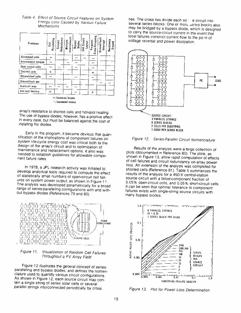
Table 4. Effect of Source Circuit Features on System
Energy Loss Caused by Various FailureMechanisms
. "?, _ _ _ .__ .5
Shadowedceils -- ____ -- -- -- jInterconnectfaligue .... ,
...... i
Open-circuitcells
Shorted cells
Mismatched'cells
Ground.faultarc
In-circuitarcs
Hot.spotheating
.... ,
-F .t- I.... i
+ L - "- '
+: Loweredlosses-: Jllcreased losses
i,,..,
4
u --
array's resistance to shorted cells and hot-spot heating.
The use of bypass diodes, however, has a positive effect
in every case, but must be balanced against the cost of
installing the diodes.
Early in the program, it became obvious that quan-
tification of the implications of component failures on
system Nfe-cycle energy cost was critical both to thedesign of the array's circuit and to optimization of
maintenance and replacement options. It also was
needed to establish guidelines for allowable compo-nent failure rates.
In 1978, a JPL research activity was initiated to
develop analytical tools required to compute the effectof statistically small numbers of open-circuit cell fail-
ures on system power output, as shown in Figure 11.
The analysis was developed parametrically for a broad
range of series-paralleling configurations with and with-out bypass diodes (References 79 and 80).
ties. The cross ties divide each so e circuit into
several series blocks. One or more Dories blocks also
may be bridged by a bypass diode, which is designedto carry the source-circuit current in the event that
local failures constrict current flow to the point of
voltage reversal and power dissipation.
_ SOURCECIRCUIT:
3 PARALLELSTRINGS6 SERIESBLOCKS2 CELLSPERSUBSTRING1 DIODEPERSERIESBLOCK
Figure 12. Series-Parallel Circuit Nomenclature
Results of the analysis were a large collection of
plots (documented in Reference 80). The plots, asshown in Figure 13, allow rapid computation of effects
of cell failures and circuit redundancy on array power
loss. An extension of the analysis was completed for
shorted cells (Reference 81 ). Table 5 summarizes the
results of the analysis for a 450-V central-station
source circuit with a failed-component fraction of0.05% open-circuit cells, and 0.05% short-circuit cells.
It can be seen that optimal tolerance to component
failures exists with single-string source circuits withmany bypass diodes.
Figure 11. Visualization of Random Cell Failures
Throughout a PV Array Field
Figure 12 illustrates the general concept of series-paralleling and bypass diodes, and defines the nomen-
clature used to quantify various circuit configurations.
As shown in Figure 12, each source circuit may con-
tain a single string of series solar cells or severalparallel strings interconnected periodically by cross
L0 _,_F-_--_,,r_-, ..... r---,--,7_ _[! 8 PARALLELSIRINGS //7/I--_r•o.m ._/
g o.i-
0.0[_ _4o0
•_ O. 001 " / ' 50 PER
P/Z/Z_ _ _ _ .......F',?.-/- )
O.0001 0.001 O.Ol 0.] 0
SUBSTRINGFAILUREDENSITY
Figure 13. Plot for Power Loss Determination
15

Table 5. Fraction Power Loss Caused by 0.05% Shorted Cells and 0.05% Open-CircuitCells for a 450-V (1000 Series Cell) Source Circuit Versus Series-ParallelConfiguration, with One Bypass Diode per Series Block
CellsPer
Substring
2O
10
SeriesBlocks
5O
IO0
20O
5OO
Top Line: Short-Circuit Losses
Cells in Parallel
0.0010.0110.012
0.0010.0050.006
0.0010.0030.004
0.0010.0010.002
4
0.0010.0500.051
0.0010.0220.023
0.0020.0100.012
0.0020.0040.006
0.0010.0250.026
0.0020.0130.015
0.0020.0070.000
0.004[].0030.007
16
0.0010.0150.016
0.0020.0080.010
0.0020.0040.006
O.OOG0.0020.000
Mid Line: Open-Circuit Losses
OptimumDesignRegion
Selisitiveto ShortedCells
Bottom Line: Total Losses
In 1979, development of the above circuit-analysistools allowed, for the first time, prediction of the life-cycle cost impact of various failure mechanisms andrates (Reference 82). A key first use of the analysis,therefore, was to examine the cost effectiveness ofvarious maintenance-relDlacement strategies based onthe replacement cost estimates resulting from theearlier Bechtel studies.
Figure 14 displays the relative life-cycle energycost for two replacement strategies as a function ofthe number of series blocks and parallel cells persource circuit. In the first strategy (solid curves), nomodule replacement is allowed, and it can be seenthat life-cycle costs increase sharply with low numbersof series blocks. This reflects the rapid array degrada-tion shown in Table 5 in the same circumstances.
0.14
0.]2
S
0.10
,,z,
o, 0.08
O.06
Figure 14.
l_ I I I l I I I I I I I 1 '1 I I I I I I 1
, CELLFAILURERATE: 1 PERlO000PERYEARi_ _ SOURCECIRCUIT" 2400SERIESBYN PARALLEL, -L _ ONE DIODEPER SERIESBLOCK
-- __DULE : 4 x 4 FOOT(144CELLS) --
"_-_ PER CELLFAILURE -
WITHNOMODULE 4 PARALLEL"_'_..,. /8 PARALLELJ .... "-- ....... _
I l I I I till I 1 l I I ltl] I I I 1 I 111[
10 100 1000SERIESBLOCKSPERSOURCECIRCUIT
Relative Life-Cycle Energy Cost Versus Series-Paralleling and Maintenance Strategy
16

For the second strategy (dashed curve) in Figure 14,modules are replaced each time a solar cell falls duringthe 30-year life of the plant. This results in no powerdegradation, but does cause a substantial modulereplacement-cost contribution. This cost also varies withthe number of series blocks because of improvements inmodule manufacturing yield that occur when moduleseries-paralleling achieves high levels.
The key conclusion drawn from Figure 14 is thatthe optimal maintenance strategy is not to replacemodules for routine sporadic cell failures, but insteadto absorb the small economic penalty associated withcorresponding gradual decrease in plant power output.
The analysis was repeated for various sizes ofmodules and system voltage levels to define optimumcircuit configuration, module size, and replacementstrategy for each system type (see References 80 and82).
F. ELECTRICAL COMPONENTS
Although a PV module primarily is composed ofsolar cells and encapsulants, two additional electricalcomponents with important functions and cost contribu-tions are bypass diodes and electrical terminations (junc-tion boxes and/or connectors). Reliability and cost issuesrelated to module electrical terminations led to earlyJPL studies of off-the-shelf candidates (Reference 83),and subsequently to a contract with Motorola and Can-non to define alternatives (Reference 84). Through theyears, collaborative work with Amp, Inc. has led to acomplete family of low-cost termination productsespecially designed for PV applications (Figure 15).
Figure 15. Low-Cost Connectors Developed for PVApplications
In circuit analysis and hot-spot heating studiesconducted by JPL, strong evidence was generated foruse of bypass diodes in array applications. Because
OF !:"L;'_, ,'
periodic estimates of the cost of bypass diodes ranged
as high as $0.50/Wp of array capacity, GE received acontract to develop improved cost estimates and todevelop low-cost mounting approaches for integratingthe diodes into modules and arrays (References 85through 88). Large-capacity bypass diodes, such as thedual 60 A diode (Figure 16), have been shown to cost
about $0.03/Wp of array capacity. One of the picturedunits is used for each 1 kW panel in the first 1 MW plantof the Sacramento Municipal Utility District (SMUD).
Figure 16. Dual 60-A Bypass Diode Used in SMUDPV Power Plant
G, ARRAY-LOAD INTERFACE CHARACTERIZATION
To control 12R power losses in power-conversionequipment, or to otherwise satisfy the load, an arraygenerally is required to provide maximum power at aspecified voltage level. Small systems (up to a fewhundred watts) generally require 12 to 24 V, residen-tial and intermediate load-center systems (from 5 to100 kW) generally require 100 to 300 V, and largemegawatt-level installations require a maximum of1000 V.
An important consideration in the design of thearrayqoad interface is that the array current is propor-tional to the instantaneous irradiance level, and the arrayvoltage decreases about 0.5% per 1 °C of increasingsolar-cell temperature. The array load, therefore, mustaccommodate substantial current and voltage variationscaused by changing ambient conditions while continu-ously maximizing the power received from the array.
To assist the designers of power-conversion equip-ment, JPL conducted an extensive study of array-loadinterface design considerations including quantification ofthe pros and cons of various load-control strategies andestimation of maximum expected array voltage and cur-rent levels (References 89 and 90). The results weregenerated parametrically in a manner useful for any arraysize, voltage level, or geographic location.
17

H. SIGNIFICANTACCOMPLISHMENTS
Specifictechnologydevelopmentsthatevolvedfromtheengineeringresearchactivityinclude:
(1) Low-costground-mountedarray-designapproachesincludingframelessmodules.
(2) Roof-mountedarraydesignapproaches.
(3) Windpressureloadsonflatmodulesandarraysincludingdynamicflutterloads.
(4) Dataonarraycleaningcostsandautomatedwashingtechniques.
(5) Guidelinesforoptimummaintenance/replacementoffailedmodulesinthefield.
(6) Module and array thermal-design guidelines forcooler operation, resulting in increased poweroutput and longer life.
(7)
(8)
Standardized module thermal testing methods.
Module electrical insulation system-designguidelines and testing techniques.
(9) Fire-resistant module designs and encapsulantmaterials.
(to)
(11)
(12)
(13)
Array series/parallel electrical circuit-designguidelines including grounding and bypass-diode design guidelines.
Module electrical terminal needs and designs.
Bypass-diode packaging and mountingapDroaches.
Design guidelines for optimally interfacingarrays with power conditioners.
18

SECTIONIV
Reliability Technology Development
A. BACKGROUND
Another key objective of the Engineering Scienceand Reliability Area of the FSA Project, together with theEncapsulation Task, was to guide and develop the tech-nology base required to achieve modules with 30-yearlives. At the beginning of the Project in the early 1970s,typical terrestrial modules were either very expensive, orhad lifetimes ranging from 6 months to 2 to 3 years. As aresult of site visits to early commercial applications andexperience with the first block procurements, it becameclear that substantial research was needed to provide the
technology required to achieve 20- to 30-year life modules.
The reliability issues of the early PV industry werenot unique to its technology, but stemmed from thegeneral lack of technology enabling prediction of thecomplex chemical and physical reactions involved inlong-term aging. Unlike more complex systems, how-ever, PV modules had the advantage of a very limitednumber of different types of components. This alloweda high level of research and testing to be focused oneach failure mechanism. Conversely, in the classicalcase of having all of your eggs in one basket, if thereis a generic problem with a component of a PV mod-ule, a large fraction of the PV system is at risk. Thisalso demanded that PV failure mechanisms be wellunderstood and solved.
During the course of the Project, a steady streamof module failure mechanisms (shown in Figure 17)was observed and identified through module testing,application experiments, and failure analyses (seeReferences 8 and 9). To resolve the reliability prob-lems, a systematic research effort was undertaken(References 1 2, 1 4, 15, and 91 ) with parallel effortsfocused on the most troublesome failure mechanisms
(Figure 18). In carrying out the research, the engineer-ing area of the Project emphasized mechanismsassociated with the solar cells, the module structure,and the electrical circuit and safety, while the Encap-sulation Task emphasized issues dealing with polymerencapsulants.
An important initial focus of the engineering researchwas the development of test methods useful for quanti-fying reliability weaknesses during the module designphase. This led to the early definition, development, andextensive refining of module qualification tests to catchknown design deficiencies, while passing modules withgood in-the-field performance (see References 4, 5, and42). As progress was made, emphasis continually wasrefocused toward achieving a physical understanding ofthe less-well-understood failure mechanisms and to
devising design solutions for them.
Yoor
Problem Aree _ 77 7g 79 'gO-[ 01 02 63" 04
Bond DelaminatJon
Interconnect Fatigue i _ ,,ll h
Metaillzatlon Corrosion i ="-.. •
Electrochemical Corrosion •
Photothermnl Degradation ,
Structural Failure
tinil-lmpact Damage
Class Breakage I i,
Cell Cracking
Voltage Breakdown • • _L
Hot-Spot Heating ,dz m_
Excessive Soiling
Module Arcs and Fixes • •
Iligh Operating Temperatures -de nil J i L
Figure 17. Periods of Occurrence of Significant FieldFailures in Various Mechanism Categories
YearTechnology
J._ I TBond Delaminetion r-J 6 v _
Interconnect Fatigue CZ _ _
Galvanic Corrosion r-z , _.
Electrochemical Corrosion _ _ E _
Phntothermel Degradation "-- -* -" -;
Structural Failure I _ Ir _ _
Hail Impact _ ]E_ILr
Glass Breakage ] _ F
Cell Fracture Mechanics _ •
Voltage Breakdown _ -* , _- ._E
Hot-spot Heating J (_. k ___ _ _ _ .._a,
Soiling I ' _
• = Major Contribution
A = Significant Contribution
Figure 18. Reliability and Durability Developments,19 74 to 1984
During the course of the Project, reliabilityresearch evolved into a general methodology with sixmajor elements:
(1) Identification of key degradation and failuremechanisms.
(2) Establishment of mechanism-specific reliabilitygoals.
(3) Quantification of mechanism parameterdependencies.
(4) Development of degradation predictionmethods and qualification tests.
(5) Identification of cost-effective solutions.
19

B. RELIABILITYMANAGEMENT
Incarryingouttheaboveresearch,thefirsttwoelements evolved naturally into an overall reliabilitymanagement function, and the third through the fifthelements were implemented as separate integratedactivities for each failure mechanism. This approach
allowed specialist teams to address individual mecha-nisms while the management activity scoped the prob-lem as a whole, established priorities for mechanism-level research within budget constraints, and providedspecific reliability goals for each mechanism.
1. Identification of Failure Mechanisms
An important reliability management activity wasto ensure that all important failure and degradationmechanisms were identified and that significantresources were not expended on less important prob-lems. A key criterion in this regard was the extent towhich a failure mechanism was generic to a majorityof state-of-the-art module designs as opposed to beingassociated with a single module or manufacturing pro-cess. Inclusion of a wide variety of test modules fromvarious manufacturers allowed this separation andhelped ensure the broad applicability of analysis andtest methods developed and solutions identified.
The most important indicator of failure mechanismimportance was found to be well documented field fail-ures (see Reference 42). This required careful monitoringof field applications with statistically significant numbersof modules, and an active problem-failure reporting sys-tem. Detailed failure analysis to identify fundamentalfailure mechanisms was a critical step.
Qualification testing also highlighted large numbersof failures, but this evidence was much less convincingbecause of the small number of samples in test and thelack of quantitative correlation to field performance.Similarly, good performance in non-operating field testracks, as contrasted to performance in operating PV sys-tems, was found to be a necessary, but not sufficientcondition for long life. In effect, system interface stressessuch as applied voltages and currents play a significantrole in PV failure mechanisms. Hot-spot heating failures,
shorts to ground, and in-circuit arcs are importantexamples of failures that required operating systems forquantification.
Unfortunately, none of the failure-identificationtechniques discussed above was found effective inidentifying long-term failure mechanisms that onlyshow up after prolonged field exposure. The study ofthese mechanisms required the development of inter-mediate length (6-month to 2-year)life tests thatincluded relevant stresses and achieved accelerationlevels of 10 to 50.
Experience during the Project has shown thatincreased temperature is the most reliable accelerator
for a variety of mechanisms. Increased humidity,applied voltage, and accentuated stress cycling also
2O
were found to be useful accelerators. Cell testing atClemson University, module testing at Wyle Labora-tories, and encapsulant testing at Springborn Labora-tories are examples of key research activities addressedto identifying important long-term mechanisms (Refer-ences 32, and 92 through 94).
2. Establishment of Mechanism-SpecificReliability Goals
Once key failure-mechanisms were identified, animportant next step in the management process wasto establish target degradation allocations for eachmechanism, consistent with the overall goal (Figure 19)of 20- to 30-year module life. A critical step in this pro-cess was quantification of the economic importance atthe system level of each failure or degradation occur-rence. For some mechanisms, such as encapsulantsoiling, the economic impact is directly proportional tothe degradation level and is easily calculated. Forothers, such as open-circuit or short-circuit failures ofindividual solar cells, elaborate statistical-economic analy-ses that included effects of circuit redundancy, mainte-nance practices, and life-cycle costing were required(see References 12, 82, and 91). Development of theseanalytical tools was described in Section III of this report.
BASELINE
s /TAaGET
mN
N
0 I I . 1
0 10 20 30 40
z YEARS
Fzgure 19. Typical Target Allocation for Time-Dependent Power Degradation
Table 6 lists 1 3 principal failure mechanisms iden-tified for flat-plate crystalline-silicon PV modules,together with their economic significances and target-allocation tevels (see Reference 14). The units ofdegradation, listed in the third column, provide conve-nient means to quantify the failure levels of individualmechanisms according to their estimated time to fail-ure. For example, units of percent per year in the con-text of component or module failures reflect a constantpercentage of components failing each year. For com-ponents that fail with increasing rapidity, percent peryear per year (%/y2) is the unit used to indicate lin-early increasing failure rate. This failure trend is mosteasily interpreted by noting that the failure rate after(A) years is (A) times the %ly 2 value. For those

Table 6. System Life-Cycle Energy Cost Impact and Allowable Degradation Levels for Flat-Plate Crystalline SiliconModules
Type of
Degradation
Componentfailures
Power
degradation
Module
failures
Failure Mechanism
Open-circuit cracked cellsShort-circuit cells
Interconnect open circuits
cell gradual power loss
Unitsof
Degrad.
I
Front surface soiling
%/yr
%/yr
%/yr 2
%/yr
Module optical degradation %/yr
%
Module, glass breakage %/yr
, M.o_u!e .open circuits %/yr
Module hot-spot failures %/yr
By-pass diode failures %/yr
Module' shorts to ground
Module delamination%/yr 2
%)yr 2
Life-limiting Encapsulant failure due Yearswearout to loss of stabilizers of'life
*k = Discount rate
Level for 10%
Energy CostIncrease*
k=O k=lO
0.08 0.13
0.24 0.40
0.05 0.25
0.67 1.15
0.67 " 1.15
10 10
0.33 1.18
0.33 1,18
0.33 1.18
0.70 2.40
0.022 0.122
0.022 0.122
27 20
Allocation
for Economic
30-year PenaltyLife
Module
0.005 Energy
0.050 Energy0.00i Energy
0.20 Energy
8.20 Energy
3 Energy
0.1 O&M
0.1 O&M
0.1 O&M
0.05 O&M
0.01 O&M
0.01 O&M
End of35
life
mechanisms classified under power degradation, thepercent per year units refer to percentage of powerreduction each year.
Using the units described above, columns 4 and 5 ofTable 6 indicate the level of degradation for each mecha-nism that will result in a 10% increase in the cost of
delivered energy from a large PV system. Because themechanisms generally will occur concurrently, the totalcost impact is the sum of the 13 cost contributions. Col-
umn 6 lists the strawman allocation of allowable degra-' dation among the 13 mechanisms to achieve a totalreliability performance consistent with expectations of a30-year life. The total effect of the allowable levels is a20% increase in the cost of energy compared to thatfrom a perfect, failure-free system.
C. RELIABILITY PHYSICS INVESTIGATIONS
Once a key failure mechanism was identified andquantitative goals were established for field-failurelevels, the challenge was to achieve the levels andknow that they had been achieved. This very difficultphase can be described as containing three researchelements: quantification of parameter dependencies,development of degradation prediction methods, andidentification of cost-effective solutions. These research
elements were integrated into the study of each failuremechanism and were the focus of the research team
addressing each mechanism. Thus, once mechanism-specific reliability goals were established, research activ-ity was divided up on a failure mechanism basis, witheach mechanism-specific team responsible for under-standing the mechanism, developing predictive test and
analysis methods (including qualification tests), andinvestigating design solutions.
A key thrust of each mechanism-specific researcheffort was to attempt to quantify the chemical and physi-cal processes involved in the degradation. Although onlya qualitative insight into the mechanism physics was nor-mally achieved, the improved level of understanding gen-erally was invaluable in identification of principal degra-dation parameters and qualitatively understanding theirinfluence. Heavy emphasis was placed on empiricalcharacterization of failure rates based on least squaresfitting a general mathematical function through a largequantity of empirical test data gathered at parametricstress levels. This technique of using carefully selectedmathematical functions to unify and interpolate amongparametric test data was found to be an excellent way toquantify mechanism-parameter dependencies. Knowl-edge of the mechanism physics played a key role inselecting the experimental parameter to be measuredand in choosing the form of the mathematical functionsto be fit to the data.
Once parameter dependencies were characterized,the problem of life-prediction required understanding thetime-history of applied stresses associated with thesubject exposure, be it 30 years of field weathering or6 months in an accelerated test environment. Substan-
tial skill generally was necessary to achieve an ade-quately accurate prediction with available resources.
During the course of the Project, a variety ofenvironmental stress characterizations were devel-
oped. These include models of hail-impact probability(see Reference 26), wind loading pressures (see Refer-
21

ence59),andarrayvoltageandcurrentdurations.Inaddition,SOLMETweather-datatapes(seeReferences30and31)wereusedextensivelytomodelUV,tempera-ture,andhumidityexposurelevelsofmodules(seeReferences32and33).Thesemodelsoftenwerecom-binedwithcomplex,degradationparameterdependen-ciestoachieveusefullife-predictionsforvariousfailuremechanisms(seeReference33).
Asa normalpartofeachmechanism-specificresearchactivity,variousdesignapproachesandmaterialswereincludedintheparametrictestingandlife-predictionanalyses.Asaresult,theseactivitiesalsoservedto identifyviablesolutionconceptsandprovidethetoolstocomputetheircost-effectiveness.Thelatterrequiredtrade-offsofdegradationrates,failurerates,andlifeagainstinitialmanufacturingcosts,field-maintenancecosts,andlostenergy revenues. Life-cyclecosting served as an excellent mathematical tool to inte-grate these disparate economic terms and to allow cost-effectiveness to be quantified and trade-offs to be made
(References 82 and 95). Models for predicting the eco-nomic impact of individual failures upon the system wereused here, as they also were in establishing the quantita-tive reliability goals described earlier. A necessary part ofdefining cost-effective solutions was to reconcile anditerate initial goals with the realities of available technolo-gies used in the most cost-optimum manner. When avail-able technologies fell short, they were highlighted forcontinued research.
The following paragraphs highlight the key reliability-physics investigations carried out during the course ofthe Project. These include research on:
(1) Interconnect fatigue.
(2) Optical surface soiling.
(3) Hail-impact resistance.
(4) Glass-fracture strength.
(5) Celt-fracture strength.
(6) Celt reliability.
(7) Long4erm temperature-humidity endurance ofmodules.
(8) Hot-spot heating.
(9) Bypass-diode reliability.
(10) Electrical breakdown of insulation systems.
(t 1) Electrochemical corrosion.
1. Interconnect Fatigue
Individual solar cells of a module generally areinterconnected in series by metallic ribbon conductorsthat lead from the bottom of each cell to the top of thenext, as shown in Figure 20. The large number ofseries cells in a high voltage (> 100 V) array makes anarray very sensitive to open-circuits caused by eithercell failures or failure of the interconnects that connect
adjacent cells (see Reference 14). Achieving highreliability requires cell and interconnect failures to beheld to low levels and that fault-tolerant circuit redun-
dancy be optimally used.
During the course of the Project, extensive researchwas conducted on interconnect failure caused bymechanical fatigue (Figure 21). This is a classical failuremechanism that has been prevalent in spacecraft arraysas well as terrestrial arrays. It primarily is caused by ther-
ARRAY
PANEL
CELL
/.- SUPERSTRATE
/-INTERCONNECT
p .........._--TOP METALLIZATION (-) •N-IYPE
DIFFUSED
S_ BOTTOM METALLIZATION1+1
Figure 20. Photovoltaic Nomenclature
22

Figure 21. Scanning Electron Microscope Image ofFatigued Interconnect
mal and humidity expansion differences between the celland its supporting substrata or superstrate.
Mon, Moore, and Ross (References 96 through 98)empirically characterized the fatigue-failure statistics ofa variety of both interconnect materials and geometries,and published detailed design methods for achievingoptimal levels of interconnect reliability. From empiricaldata, interconnects were found to fail with a log-normaldistribution, with the weakest failure occurring as muchas 100 times sooner than the average. Figure 22 pre-sents example fatigue curves that quantify the probabi-listic nature of the failure of copper interconnects.Because of statistical variability, the use of multiple inter-connects was found useful in preventing open circuitscaused by failure of the interconnects or their attach-ments to the cells. Methods also were derived that allowusers to select optimal levels of interconnect redundancybased on minimizing life-cycle energy costs of an array(see References 96 through 98).
100 ....... ,-, ...... ,,_ ...... _,.
10-1
10-2
10-3101
log &_ = -0.3228 log N - 1.0148 * 0.9998p-1.4839p2 • 0.9019p3
J
e_
j0.99jO.80_0.50_0.30_0.10jO.03
102 103 104 105 106
CYCLES,N
Figure 22. Fatigue Curves for OFHC 1�4-HardCopper Versus Failure Probability (p)
(_]__,,L_'[t'_ Figure 23 presents the life-cycle energy cost (as a
percentage of total PV system cost) for a variety ofsolar cell interconnect materials as a function of inter-connect thickness (see Reference 97). The plottedcosts include manufacturing costs, efficiency lossesbecause of solar cell shading and 12R losses, andpower degradation because of interconnect fatiguefailures. The latter are responsible for the rapidly risingtrend on the right side of each cost curve, Such ananalysis allowed quantitative judgments to be madeand cost-effective levels of reliability to be selected.
a_
;E
uJ
s
1oo
1o
STRAIN,/%60.004 0.008 0.0012 0.0016
, i i i
/ ALUM,.UM C/// 16 Cul68SSI16
12.5 Cu175INVII2.5Cu
7THICKNESSIt),rolls
Figure 23. Life-Cycle Cost Contribution of DoublyRedundant Interconnects as a Function of
Material Thickness (1 mil = .0254 mm)
2. Optical Surface Soiling
Loss of module power because of soiling of thefront surface encapsulant was a critical problem withearly silicone-rubber modules of the mid 1970s (Refer-ence 99). As a result, an extensive test program was
conducted at a variety of site locations throughout theUnited States to characterize the nature and level of
soiling with various encapsulants (Reference 100).
Although similar in effect to other optical-lossmechanisms, the experimental data indicated that opti-cal surface soiling caused by dust and atmosphericcontaminants reached equilibrium levels in a fewweeks and then fluctuated somewhat with natural
cleaning mechanisms such as rain. Figure 24 illus-trates this soiling behavior for a variety of module sur-face materials in two site environments: one urban, the
other remote. The severe soiling behavior of a typicalunprotected silicone rubber is clearly visible.
Although the data indicate that, without washing,average soiling levels below 5% should be easilyachievable with glass or Tedlar-like optical-surfacematerials, it also was observed that the effect of soil-
ing is greater at non-normal angles of incidence. Astudy subsequently was conducted that characterizedthe angular dependence of module electrical efficiency
23

5O
4O
Z
03 3C03
oF-z 20wU
1G
JPL (URBAN}I ' i I I
.fTEDLAR.-. • ,*.,/-GLASS
,.'N-. "'. x ... ..... "
I I I .I I
0 I 2
FIELD EXPOSURE, years
TABLE MOUNTAIN (REMOTE]50I I I .... I I I
40I
3ot
20}
lol
OIO
AS_
1 2
FIELD EXPOSURE, years
Figure 24. Loss in Array Short-Circuit Current (Isc)Because of Soifing Versus Years of FieldExposure
(with and without soiling) on off-normal irradiance, anddeveloped analytical models for use in energy per-formance calculations (Reference 101 ).
Research attempts also were made to develop alaboratory soiling-resistance test (see References 4 and100). These were only marginally successful because ofthe complex soilingand cleaning processes in the naturalenvironment. Because the soiling behavior becomesapparent quickly in the field, natural outdoor soiling testswere adopted as the most reliable means of characteriz-ing the self-cleaning properties of front-surface encapsu-lants. Based on empirical soiling data, general theories ofsoiling were hypothesized and anti-soiling coatings-weredeveloped within the Project's Encapsulation activity(Reference 102).
3. Hail-Impact Resistance
Another source of early module failures wasimpact by hailstones. In the 1976 to 1978 time frame,extensive research was conducted to develop meansof testing hail-impact resistance of various moduleconstructions and to define cost-effective protectionapproaches and levels (Figure 25). As an excellentexample of the integrated nature of the reliability-physics efforts, research developed the hail-impactgun shown in Figure 25, defined the qualification testnoted in Table 1, and provided definitive designguidance for achieving the required levels of protec-tion (References 103 and 104). The final Block Vrequirement for resistance to f-in.-diameter hailstonesis based on field experience that indicated this level ofprotection is necessary to achieve acceptably lowprobabilities of failure, even in low hail-incidenceregions of the country.
4. Glass-Fracture Strength
During the first central-station array-design studyconducted by Bechtel Corp., it was discovered therewere neither readily available methods for determiningthe stress in glass associated with uniform wind pres-
sure loads, nor were there reliable data on the strengthof glass. Typical linear theory for stress versus load ledto unreatisticty thick glass, thus ruling out large 4 x 8 ftPV modules. The principal problem was thin glass sheetsundergo large out-of-plane deflections that make linearstress-deflection relationships in error by as much as afactor of two. The fracture strength of glass also is acomplex, poorly-documented function of such things asglass area, time of loading, flaw.distribution statistics, andresidual stress (temper).
In 1978, JPL and Bechtel (see Reference 19) con-ducted detailed investigations of stress distribution inglass using non-linear finite-element structural-analysiscomputer codes. These investigations were successfulin understanding the stress in glass during large out-of-plane deflections and set the stage for close collabora-tion with the community of glass researchers. As onesolution to reducing glass support requirements,Bechtel Corp. studied the concept of a curved glassmodule (see Reference 75).
JPL researchers collaborated with glass researchersat Texas Tech University, Pittsburgh Plate Glass Corp.,and Ubby Owens Ford, and developed definitive stress-prediction algorithms and glass-strength data (Refer-ence 105). Non-linear finite-element computer codeswere used to develop generic non-dimensional solu-tions for stress versus loading level (Figure 26) andmore than 2000 individual breaking-strength data wereused to characterize accurately the breaking probabilityof glass as a function of maximum tensile stress, platearea, time of loading, and temper (Figure 2_7)(Reference 106).
5. Cell Fracture Strength
Breaking of thin, crystalline-silicon solar cells wasanother problem prevalent in early PV modules. Tobetter understand the parameters that determined thebreaking strength of silicon solar cells, a novel testmethod was developed and an extensive test programwas conducted. Definitive data, as shown in Figure 28,provided an extensive characterization of the effect ofvarious cell-processing steps on the fracture probabil-ity of crystalline-silicon wafers (References 107through t 09).
6. Ceil-Reliability Investigations
CrystaWine-siticon solar cells sometimes exhibitreliability problems related to increased series resis-tance, junction shunting, and deterioration of the cellantireflective (AR) coating. Increased series resistanceoften is associated with a gradual deterioration ofadherence between the cell metallization and the cell
bulk material caused by corrosion-related processes,or the deterioration of the ohmic contact through theformation of a Schottky barrier. Junction shunting,which is much less common, may be caused by diffu-sion or migration of metallization elements into the celljunction or over the external surfaces of the cell. Thethird cell-degradation mechanism relates to the deteri-oration of the AR coating on the solar cell's irradiated
24

HAIL IMPACT RESEARCH
OBJECTIVES
• DEVELOP HAIL TEST APPARATUS AND
PROCEDURE AND CONDUCT RESEARCH
ON MODULE FAILURE MECHANISMS
CAUSED BV HAlL IMPACT
• DEVELOP STATISTICAL DATA DEFINING
PROBABILITY OF IMPACT BY VARIOUS
HAIL SIZES IN GEOGRAPHIC REGIONS OF
UNITED STATES
• CONDUCT MODULE HAIL RESISTANCE
COST/BENEFIT ASSESSMENT
SUSCEPTIBLE PARTS
• CELLS (ESPECIALLY EDGES NEAR
ELECTRICAL CONTACTS)
ENCAPSULANT SYSTEM (CORNERS AND
EDGES, POINTS OF SUPERSTRATE SUPPORT,
POINTS OF MAXIMUM DISTANCE FROM
SUPERSTRATE SUPPORT)
EXPERIMENTAL HAILRESISTANCE
TEST APPARATUS
HAIL IMPACT RESISTANCE
HAIL iMPACT DAMAGE
ON DEVELOPMENTAL MODULE
13/4An. ICE BALL)
Figure 25.
TOP SURFACE MATERIAL
CLEAR SILICONE POTTING
0.10 in+ ACRYLIC SHEET
0.09 in. ANNEALEO GLASS
(ALUM SUBSTRATE
0.12 in. ANNEALED GLASS
0.12 in+ TEMPERED GLASS
0.19 in+ TEMPERED GLASS
Hail-Impact Test Development and Data
_ FAILURE RANGE
NO DAMAGE
1B
BE
/05 1'o 1'5 2'o
HAILSTONE DIAMETER - in.
100G0
• 1000%b
I
loJ1o
Figure 26.
_. _,3 /Z///
//// C_R,.RESSB_,OW.R_AK,.CURVES
_//./// CORNER SIRESS ABOVE BREAK IN CURVES
lO0 I000 I0_ I0_0
pb4
LIF • LOAD INTENSITY FACTOR --_.
Glass Stress Curves. Maximum Principal Stress Versus Load
25

24
20
18
_N T4
•.,_d 12
EI0 8
4i
zl
0OOI
TEM_
0 _,_'Q BOWLEGANDSUGARMANOAT,_,PL,_TEGLASS• • • 80WLESANDSUGARMANDATA,SHEETGLASS
_) TEXASTECHDATA, WEATHEREEIGLASS.JPL_ATA. TEMPEREDgLASS
&2 05 I 2 5 lO 20 30 AJO 80 70 90 90 95 98 99 99.8 999
PI " PgOBABILITYOFFAILURE,%
Figure 2 7. Maximum Stress Level (al 1) Required toBreak a Given Percentage of IdenticalGlass Plates
1.o
>-0,8._J
"_ 0.6
0.4
_ 0.2
00
TWIST STRENGTH, ";-s' MNm-2
100 200 300 400 500
i I [ O[ C_I [ r I I I
t'F _,
_, _ s-cuTI 0 _ ,'
_ OO_ /_j//'_ • EDGE R©UNDED WAFERS
_ 7//. ,_, CHEM. POLISHED WAFERS_J TEXTURE ETCHED WAFERS, LOT E
, C-' COMPLETED CELLS, LOT AI I I . i I
10 20 30 40 50 60 70 80
TWISTSTRENGTH, "rs, ksi
Figure 28. Effect of Cell Processes on the FractureStrength of Silicon Wafers and Cells
surface because of leaching or contamination fromplating or corrosion products. All of these mechanismslead to a gradual reduction in a cell's electrical effi-ciency and are quite sensitive to the choice of metalli-zation and AR coating materials and processes.
In 1976, JPL initiated a contract with ClemsonUniversity to conduct an investigation and characteri-zation of the reliability attributes of a broad cross-section of available commercial and research solarcells. Between 1976 and 1986, Clemson personnel
tested hundreds of solar ceils from most of the leadingcell manufacturers and developed definitive methodsfor cell-reliability testing. Their work shows thatmoisture and thermal aging are key environmentalstresses, and that the module encapsulant systemexacerbates the problem as often as it helps(References 92 and 1 t0).
In all three mechanisms, the most effective tech-niques identified for quantification of expected levelsof degradation involve accelerated temperature/
humidity testing together with Arrhenius plotting andother means of relating the data to long-term useconditions.
7. Long-Term Module Temperature-HumidityEndurance
Complementing the Clemson University researchon cells, long-term temperature-humidity testing ofcomplete modules was conducted by JPL personnelusing the facilities of Wyle Laboratories in Huntsville,Alabama, This test program focused on the synergisticreactions between cells and the module encapsulantsystem and highlighted problems such as electro-chemical corrosion of cell metallization, chemical con-
tamination from edge seals and gaskets, and catalysisof encapsulant yellowing by cell and bus bar metallicions. Research results provided definitive estimates ofthe expected reliability of several module constructiontypes that used leading encapsulants and cell-metallization systems (see References 32 and 93).
8. Hot-Spot Heating
A unique failure mechanism associated with solarcells is excessive local hot-spot heating that can occurwhen a cell or group of cells is subjected to a currentlevel greater than the cell's short-circuit current. Asshown in Figure 29, this condition can be caused by avariety of circuit faults such as cell cracking, localshadowing, and open-circuiting of series/parallel con-nections When the degree of heating exceeds safelevels (100 to 120°C in most modules), the module's
encapsuiant system can suffer severe permanentdamage (Figure 30). Preventing such damage requiresthe use of bypass diodes or other corrective measuresto limit the maximum heating level. Many investiga-tions have led to a definitive understanding of thephenomena, rneans of determining the number ofbypass diodes required, and test methods to verifythat hot-spot heating is limited to safe levels(References 111 through 11 3). For most cells andmodule constructions, a bypass diode is requiredabout every 10 to 15 series cells.
9. Bypass Diode Reliability
Bypass diodes, as shown in Figure 31, are animportant means of improving array reliability. At thesame time. they introduce additional failure mecha-nisms including diode shorting under conditions ofexcessive junction temperature, and diode shorts toground because of inadequate electrical isolation from
26

---CRACKEDORSHADOWEDCELL
FOPEN CIRCUITSUBSTRING
/ \
\ / Y-v ? -"-"v DISS,'^T,o
OF POOR QUALITY
.._A+B
V
Figure 29. Visualization of Hot-Spot Cell Heating
EXPERIMENTALAPPARATUS HOT SPOT
EMPERATURE, °C
MODULECONSTRUCTION 100 120
I
SILICONE JRUBBER
OVER
FIBERGLASS
POLYESTER
SUBSTRATE
SILICONE
RUBBER
OVER
ALUMINUM
SUBSTRATE
ONSETOE I JGLAss CARBON_TIONISUPERSTRATE
PVB
MY LAR
OBSERVEDMODULERESPONSEvs CELLTEMPERATURE
140 160 I B0
I I i
CELL BREAKDOWN JENCAPSULANT DE LAMINATION
J CRACKED CELLS
J CELLBREAKDOWN
CARBONATION
OVER HALF OF CELL
J ENCAPSULANF DISCLORED JAND SMOKING
Figure 30. Hot-Spot Endurance Test Development
grounded heat-sink assemblies. Work carried out at
GE (see Reference 88), as part of its bypass-diodepackaging study, indicates that very little historicalreliability data are applicable to the PV module-bypassapplication, which involves long periods of low reversevoltage (5 V) together with periodic high forward cur-rents. Because diode junction temperature is thecritical factor related to long-term reliability, JPLdeveloped detailed test procedures for measuringjunction temperature in situ under simulated worst-case field conditions, and defined guidelines recom-mending that the junction temperature of silicon diodesbe maintained below 125°C under conditions of max-
imum bypass current and ambient temperature(Reference 114).
10. Electrical Breakdown of Insulation Systems
From a safety point of view, an important modulefailure-mechanism is breakdown of the electrical insu-
lation system between the cell circuit and groundedmodule exterior surfaces. The maximum voltage stressincludes consideration of maximum open-circuit arrayvoltages achieved under low temperature (O°C) andhigh irradiance (1O0 mW/cm2), as well as transientovervoltages, for example, because of system feed-back of lightning transients. The latter is bounded bythe characteristics of incorporated voltage-limitingdevices such as metal-oxide varistors (MOVs).
27

Figure 31. Typical Bypass-Diode Installation Integralto a P V Module
Early interest in voltage-withstand criteria for high-voltage central-station applications led to a first explora-tory study of insulation design practices for PV modulesby Bechtel Corp. in 1978 (see Reference 75). The workpointed up a major deficiency in our understanding of thebreakdown phenomena in general, and highlighted a lackof available insulation design methods, specifically fortong-term direct-current applications involving outdoorweathering of insulation materials.
Research was conducted on various aspects ofthis problem and has led to extensive characterization
of insulation flaws present in films of Mylar and Tedlar(Figure 32), and of the field-stress enhancement thatoccurs in the vicinity of sharp edges of conductors(References 11 5 and 116). Other work on the voltage-withstand ability of encapsulants led to improvedunderstanding of the intrinsic breakdown-strength ofpolymers (References 117 and 118). Work on electro-chemical corrosion led to leakage-current studies thatdeveloped a definitive understanding of the role ofmoisture in the determination of ionic conduction prop-erties of module encapsulants and in the quantificationof the relative roles of surface, bulk, and interface con-
duction (References 119 through 121 ).
HIGH VOLTAGE THIN FILM
INSULATION BREAKDOWN
RESEARCH APPARTUS
Figure 32.
10.0
>
>IJJ
<
b 1.00
121
_J
<
0.1
0.0001 0.001 0.0t 0.10 0.50 0.80
PROBABILITY OF BREAKDOWN p
.... - .....
____i///A!__7;L_k___I '__ ..... ._A/:_ _ HhPOT__S_z_TENTIALZ
/// /
i | E : 100 SO 30 TR, l-rail1 F : 100 BG 30TR, l-railG : 200 SG 40 TR, 2-rail
i i i i i i I I i I I I i I I i i
0.99
THIN FILM
TEST BREAKDOWN DATA
Insulation Breakdown Research
.OEpomRqUALiTY
28

11.ElectrochemicalCorrosion
Electrochemicalcorrosionofsolarcellmetallizationsfirstwasobservedinlong-termtestsofmodulesunderacceleratedtemperature-humidityconditionsatWyleLaboratories.Corrosioniscausedbyleakagecurrentsassociatedwithmigrationofmetallicionsbetweenmodulecomponentsoperatingatdifferentvoltagelevels.Ofmostconcern,asshowninFigure33,isthetransportofcellmetallizationbetweenadjacentcellsandbetweenthecellsandthegroundedmoduleframe.Withtime,cellperformanceisdestroyedandcorrosionproducts,suchasthedendritesshowninFigure34,maybridgetheinsulationwithaconductivepaththatresultsinashorttothegroundedmoduleframe.
ResearchconductedduringtheProjectquantifiedtherelationshipbetweenchargetransferandcell-performancedegradation(Figure35)anddevelopedadefinitiveunderstandingof theroleofencapsulants,moisture,andtemperatureinestablishingcorrosionrates(References119through124).
D. SIGNIFICANTACCOMPLISHMENTS
Keyaccomplishments,resultingfromreliability-researchactivities,includedthefollowing:
(1) Developeddefinitiveallocations for the relia-bility required for each module failure-mechanism and defined the economic
impact of each failure.
(2)
(3)
Developed analytical tools and design data forboth the prediction of interconnect fatigue andthe design of Iong4ife, reliable cell interconnec-tions.
Developed long-term soiling data for variousmodule surface materials.
Figure 34. Dendritic Growth from ElectrochemicalCorrosion of Solar Cell Metallization
CELL
METALLIZATION _
"" I / / CELLf':'::'l / / {ANODE) I,"
"Ill i I':"• ..-,'.': ;..'.,,:.,...... .:;::,':POTTANT .... :,. II I I I I I
-'q'.. _,-$ i,'ELECTROLYTE_..:,.,olll | II | | | II | II II |.,. ,.,
;-.,_... ..... .#.. ,#..... ,......... .,.,• L,,:t,'__. :"; ';"-'.'-": -""- " -"".';'-'-'*";': :." 'r" N\\\|"_--_\I
FRAME POTENTIAL(CATHODE} DIFFERENCE
METALLIZATION IONS FOLLOWELECTRIC FIELD LINES BETWEENCELL AND FRAME
1GLASS
. , . . . _,-_ . " METALLIZATION IONS OFTENCELL---..._._., • = #. :, " ..;1 .. -..." PROCEEDTO,ANDTHENALONG,
I,_-'_'__ + "{",/''' ":,<" ': : INTERFACIAL SURFACES
I..-'_...: ".,_'. ..',..-',..':.,,\SUBSTRATE [. ° "- - ,, '. _, ,Z,... "% ..... •
Figure 33. Schematic Representation of Electrochemical Corrosion
29
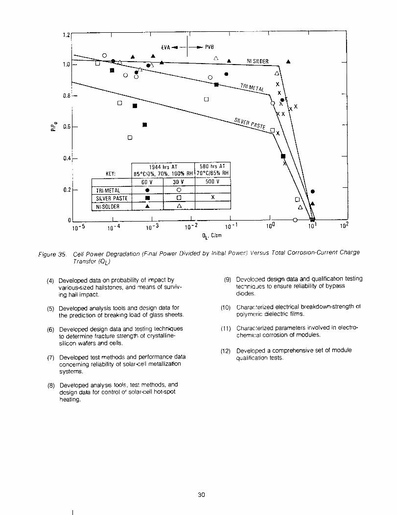
[]0 0 0
=__
[]
[]
KEY:
Figure 35.
1944 hrs AT85°C10%,70%, 100% RH
580 hrs AT70°CI85% RH
60 V 30 V 500 V
TBI.METAI_ • .... 0
SILVERPASTE II [3 X
NI.SOLDER • ,'_
0¸ I [ I I I
10 -5 10-4 10-3 10-2 10-1 100 101 102
0L, Clcm
Cell Power Degradation (Final Power Divided by Initial Power) Versus Total Corrosion-Current ChargeTransfer (QL)
(4)
(5)
(6)
(7)
(e)
Developed data on probability of impact byvarious-sized hailstones, and means of surviv-ing hail impact.
Developed analysis tools and design data forthe prediction of breaking load of glass sheets.
Developed design data and testing techniquesto determine fracture strength of crystalline-silicon wafers and cells.
Developed test methods and performance dataconcerning reliability of solar-cell metallizationsystems.
Developed analysis tools, test methods, anddesign data for control of solar-cell hot-spotheating.
(9)
(10)
(11)
(12)
Developed design data and qualification testingtechniques to ensure reliability of bypassdiodes.
Characterized electrical breakdown-strength ofpolymeric dielectric films.
Characterized parameters involved in electro-chemical corrosion of modules.
Developed a comprehensive set of modulequalification tests.
3O

SECTIONV
Module Development and Testing
A. BACKGROUND
Through the years, the FSA Project engaged in anextensive effort to develop the module technology(materials, processes, and reliability) required to meetthe early-defined cost, efficiency, and lifetime goals.To measure technology progress, it was necessary todevelop modules embodying the developed technol-ogy and to evaluate the modules. For this purpose, aseries of five "block buys" of modules was conducted.This effort was supported by development of methodsto: (1) conduct qualification tests, (2) perform accurateelectrical measurements of module power, (3) performfailure analysis on modules, and (4) conduct field tests.
An important by-product of the block buys was thecontinuous transfer of technology directly into the com-panies manufacturing modules for the market. This pro-cess permitted the latest technology to become availablenot only in production modules, but also for procurementby the Project and by other DOE-sponsored organiza-tions for use in large application experiments from whichreports on module performance could be obtained.Throughout the life of the Project, the results from qualifi-cation tests, field tests, application experiments, and fail-ure analyses were used in refinement of module designand test requirements and in identification of needs forengineering science and reliability-physics research.These interrelationships are shown in Figures 36 and 37.
B. THE BLOCK PROGRAM
The block buys consisted of a sequence of fivemodule procurements: Block I through Block V (seeReference 7). In early 1 976, at the infancy of the tech-nology, Block I was a procurement of existing terres-trial modules from four manufacturers. This first mod-
ule procurement was to establish the state of the art.The Block II procurement (Reference 125), initiated inlate 1976 with higher performance and reliability stan-dards, also involved four manufacturers. The Block Illprocurement (Reference 126), started in early 1978,consisted of large orders of modules (30 to 50 kW each)from five manufacturers. These essentially were pro-duction quantities of the Block II modules, with slightlyrevised specifications, needed for large applicationsprojects. The Block IV program (Reference 127), initiatedin 1980, included a pre-production phase that was fol-
lowed, after satisfactory completion of qualification tests,by small production contracts. This program, whichincluded more severe module requirements than theprevious blocks, produced eight qualified designs fromseven manufacturers. The Block V program (Refer-ence 128), in response to yet more rigorous specifica-tions, yielded successful designs from five contractors.
INFORMATION FLOW
IFIELD SITES AND r
APPLICATIONS
K>
I FSA JENGINEERING
K>INDUSTRY
FSA PROJECTSYSTEMS ENGINEERING
TESTS AND APPLICATIONSSTANDARDS ACTIVITIES
• SYSTEM NEEDS/SENSITIVITIES• ARRAY FIELD EXPERIENCE• TECHNOLOGY CAPABILITY• RAW WEATHER DATA
• ENGINEERING ANALYSIS• ENVIRONMENTAL ASSESSMENT• EXPLORATORY TESTING• DESIGN OPTIMIZATION
• ENVIRONMENTAL STRESS LEVELS• PERFORMANCE CRITERIA• PERFORMANCE DATA• DESIGN GUIDELINES• LOW COST DESIGNS• ANALYSIS TOOLS• TEST METHODS
Figure 37. Information and Flow
MODULE AND _._
ARRAYDESIGNREQUIREMENTS
RELATED ]TECHNOLOGIES
RESEARCH
t t
DESIGN SYNTHESIS
ANALYSES,EXPERIMENTS,
AND COST
EFFECTIVE SOLUTIONSMODULE EVALUATION
PROTOTYPE MODULE
OUALIFICATION AND
ACCELERATED TESTING
f
-t°u"""'°°"'°tt-I"LIFE PREDICTION QUANTIFICATION OF
AND ACCELERATION DEGRADATION
TEST CAPABILITIES MECHANISMPARAMETERS
IN-FIELD EVALUATIONPRODUCTION MODULES
AND ARRAYS
LONG-TERMOPERATIONAL
CONDITIONS
30-YEARLIFE
TECHNOLOGY
Figure 36. Module/Array Technology Development
31
Thegeneralmodelfortheblockprogram(seeReference6)consistsofthefollowingsequenceofevents:
(1) FSApreparesdesignandtestspecification.
(2) FSAconductscompetitiveprocurementsculminatinginawardofparallelcontracts.
(3) Contractorperformsmoduledesign.
(4) FSAconductsdesignreview.
(5) Contractormanufactures10modules.
(6) FSAperformsmodulequalificationtests(andfailureanalysis,asapplicable).
(7) Contractor modifies design and/or processingprocedure to correct problems revealed byqualification tests.
(8) FSA conducts design review.
(9) Contractor manufactures 10 modules.
(10) FSA performs module qualification tests (andfailure analysis, as applicable).
(11) Contractor modifies design and/or processingas necessary and supplies modules for retest.
(12) FSA completes final testing.
(13) FSA prepares and issues User Handbook (seeReferences 125 through 128) describing con-struction details and performance of successfulmodule design by each contractor.
Principal ingredients responsible for the successof this approach are the competitive procurements, theFSA design-and-test specification, and the continuouscooperative interaction between FSA and the contrac-tor. The competitive procurement provides incentive toincorporate the latest technology. The design and testspecification identifies design improvements needed toimprove performance, as revealed by results of priorqualification tests (from preceding block), field experi-ence, and Project research. Interaction between FSAand the contractor is the means to apply all availabletechnical resources to the guidance of the design andsolution of problems. Not the least part of this inter-action is the provision that FSA qualification tests andfailure analysis provide the vehicle for unearthing andcorrecting flaws, rather than merely identifying successor failure.
1. Qualification Tests
The purpose of the qualification tests (seeReferences 6 and 7) ('Figure 38) was to assess theability of the modules to withstand environmental and
electrical stresses expected in the field. Because the
most basic criterion for degradation is module power-output, preparation for the tests included a modulecharacterization-phase that included the followingmeasurements:
(1) Voltage and current temperature coefficients.
(2) NOCT.
(3) Current-voltage (I-V) characteristic.
After characterization and visual inspection,modules were subjected to two electrical tests:
(1) High-voitage isolation.
(2) Ground continuity.
The next events, a series of environmental tests,included:
(1)
(2)
(3)
(4)
(5>
Temperature cycling.
Humidity soak at high temperature.
Mechanical load cycling.
Hail impact.
Twisted mounting surface.
After each test, module power output wasmeasured and visual inspection was performed. Aftercompletion of all tests, the high-voltage isolation andground continuity tests were repeated.
One additional test, Hot-Spot Endurance, was per-formed on a single, specially instrumented module setaside for this test only,
Among the unique environmental testing facilitiesthat had to be developed to perform the above testswere hait guns, mechanical cyclic-loading apparatus(Figure 38), hot-spot test equipment, and test racksand instrumentation for NOCT.
Qualification tests were performed on more than1 50 different module designs, including:
(1) Blocks I through V.
(2) Commercial (U.S. and foreign).
(3) DOE Residential Experiment Stations.
(4) Georgetown Project.
(5) india Project.
(6) SMUD Project.
32

ELECTRICAL PERFORMANCE MEASURED AND PHYSICAL DURABILITY ASSESSED
INITIAL EVALUATION
- ELECTRICAL PERFORMANCE
-- V_SUAL AN0 MECHANICALINSPECTION ANDCHA_CTEmZAT_
INSULATION TEST
-- NOMINA L OPERATING CELLTEMPIRATURE {NOCTIDETERMINATION
- VOLTAGE AND CURRENTTEMPERATURE COEFF)CIENT
D(TERMI NAI'IO N
THERMAL CYCLE HU M IO1TITE_IFREEZl N LOADINGTEST TEST
I EXTENDED THERMAL CYCLE
'' II EV I I ELECTRICAL PERFORMANC[VISUAL INSPECTION
TWIST _ HAIL
IMPACT
I
FINALEVALUATION
E_CTnlCAL_RFORMANCE
_L VISUAL INSPECTION
INSULATION TEST
EVALUATION OFCHANGES
TYPICAL THERMAL CYCLING TEST
MAXIMUM CYCLE TIME_
wl_ liTrlr r Ilr_Iil; il fi_ ilwilr Iil_l_
i 90I _--"--_ iCONTINUED FOR
<[ / I(XPC/hr / \150 cycles
"¢' 2Sk /MAXfMUM/ _k _ 7
| IY / ,'-401- " " II _------J -
_J JlJ I_JlJJl] ltl Jlllllll_liJLIJ L_ llil
1 2 3 4 5 i
TIME (hi)
HUMIDITY-FREEZING CYCLE
k-<(
tr
_0p-
:S
CONDITION FREEZING
_al;% ± 2.§% RH I /_06% I 25%RH-
- f _ \ C .....
i_---_--100eC_hr MAXIMUM----_--_ / FOR 10
_mr
MAXIMUM_ x 0.Shr MINJMUN
TiME Ihr)
I
CYCLIC PRESSURE LOADING TEST APPARATUS
t
HAIL TEST APPARATUSVISUAL INSPECTION
LARGE-AREA
SOLAR SIMULATOR TESTINGTESTS
THERMAL CYCLE
HUMIDITY CYCLE
MECHANICAL
LOADING CYCLE
WIND RESISTANCE
TWIST
HAIL IMPACT
! ELECTRICAL
ISOLATION (rolls)
GROUND
CONTINUITY
HOT.SPOT
ENDURANCE
• REB - RESIDENTIAL
BLOCK I
SO
5
QUALIFICATION TEST SPECIFICATIONS
MODULES
BLOCK It BLOCK lit BLOCK IV" BLOCK V"- REStlL RESelL
SO 50 50 SO/2SO
5 5 5 10
10_ 11_ 10000 i0000
X X
X X X X
l X X
X
TEST LEVELS
-40'C TO + _r cYCLES AS INDICATED
§ CYCLES AT 16% RH. 23_C TO 40_C OR
10 CYCLES AT 85% RH, 40"C TO +8E_C
2400 Nlm 2 (50 Ib/ftZ), CYCLES AS
INDICATED
UNOERWRITERS LAB TEST NO _17
(Ree_dentll onlyl
ONE CORNER LIFTED 2 cm/meter OF
LENGTH
20 mm DIAMETER HAIL - 23 roll
50 p A MAX CURRENT AT VOLTAGE
INDICATED
SO m/lBcd_ MINIMUM REBIBTANCE TO
GROUND FOR EXPOSED CONOUCTORB
100 hr SHORT CIRCUITED AT NORMAL
OPERATIN100mW_c_m _ CELL TEMPERATURE AND
IL - INTERMEDIATE LOAD
Figure 38. Module Qualification
33

These qualification tests provided internationallyrecognized assessments of PV module electrical per-formance and reliability that provided needed credibilityfor the developing PV industry.
2. Failure Analysis
When problems occurred during qualification testsor field tests, or at array installations, it was necessaryto perform an in-depth failure analysis to find the exactcause of the problem. A Problem Failure Reportingsystem (Reference 129) was established by the FSAProject in 1975 to provide formal reporting of all fail-ures, regardless of site of occurrence. This system
reported about 1200 module failures. The reports andfailed modules were delivered to failure-analysis per-sonnel who then applied a variety of sophisticatedtechniques to isolate the specific cause of the failure(see Reference 10) (Figure 39). Some of these tech-niques were derived from the National Aeronauticsand Space Administration (NASA) space explorationprogram and some were developed especially for theterrestrial PV program. A highly detailed report,describing each such analysis, presented the resultsalong with recommendations for correcting the moduledeficiencies. These Performance and Failure AnalysisReports were supplied to the manufacturer of the mod-ule and to JPL personnel responsible for module-development research. Such analyses, performed onmore than 435 modules, were instrumental in correct-ing design and processing problems to the extent thatnew modules incorporating the recommended changesthen were successful in passing the qualification tests.
Among special test devices developed specificallyfor failure analysis of PV modules were the Sun-U-Lator(see Reference 9) and the Solar Cell Laser Scanner(Reference 130). The Sun-U-Lator is a test chamber inwhich illuminatior_ is applied cyclically to enable detec-tion of module intermittent failures observed in the field
during thermal stress changes. The Solar Cell LaserScanner provides a laser sweep of an entire module. Theoutput photocurrent produces a two-axis image on acathode ray tube (CRT). The image appears as a photo-graph of the module, with an intensity pattern showingthe performance of every cell, as affected by anomaliessuch as cell cracks, variations in shunt resistance, andcircuit discontinutties.
3. Field Tests
From the initiation of the Project, it was obviousthat data on performance of modules in the field werenecessary to identify both research needs and technol-ogy progress, tn 1976, JPL set up four field test sitesin California. in 1977, NASA Lewis Research Centerset up 12 sites in the contiguous United States,Alaska, and the Panama Canal Zone. Modules suppliedby JPL were deployed at all t6 sites (Figure 40). In1979, the Lewis sites were turned over to JPL. Thiscomplex of 16 sites provided a broad variety of environ-ments: mountain, desert, marine, hot and dry, hot andhumid, cold, moderate, windy, and high pollution(Reference 131 ).
MODULE PROBLEM/FAILURE ANALYSISX-RAY OF OVERHEATED
CELLS SHOWING MELTED SOLDER
PHOTOMICROGRAPH OF HAIL DAMAGE
LASER SCAN OF MODULE
OUTPUT SHOWING CRACKED CELL
HIGH VOLTAGE
BREAKDOWN
OFINSULATOR
CELL INTERCONNECT FAILURE
• PROBLEMS/FAILURES AT TESTIAPPLICATION
SITES REPORTED
• JPL AND MANUFACTURER EVALUATE
PtF AND DETERMINE CORRECTIVE ACTIONS
• MANUFACTURER CHANGES MODULE
DESIGNOR WORKMANSHIP AS NEEDED
F/gure 39. Modufe Problem�Failure An_/ysis
34
ORIGINAL PAGE ISOF POOR QUALIFY

MODULE FIELDTESTING-16 SITES
PASADENA. CA (JPL)
PRIME SITE FOR FIELD
TESTING
HOUGHTON, MI
TYPICAL REMOTE SITE
Figure 40.
FIELD TEST SITES
EXTREME WEATHER
FORT GREELY. ALASKA (ARCTIC)
FORT CLAYTON, CANAL ZONE (TROPIC)
MARINE
KEY WEST, FLORIDA
SAN NICOLAS ISLAND, CALIFORNIA
POINT VICENTE, CALIFORNIA
HIGH DESERT
ALBUQUERQUE, NEW MEXICO
DUGWAY, UTAH
GOLDSTONE. CALIFORNIA
MOUNTAIN
MINES PEAK. COLORADO
TABLE MOUNTAIN, CALIFORNIA
URBAN COASTAL
NEW ORLEANS, LOUISIANA
NEW LONDON, CONNECTICUT
MIDWEST
CRANE. INDIANA
UPPER GREAT LAKES
HOUGHTON, MICHIGAN
NORTHWEST
SEATTLE, WASHINGTON
URBAN SOUTHWEST
PASADENA, CALIFORNIA
Module Field Testing (16 Sites)
Modules were deployed at the field sites as theybecame available from Blocks I, tl, and Ill procure-ments. Periodically, the modules at these sites werevisited by a JPL team to perform visual inspection formechanical degradation and to measure electrical per-formance. These visits identified problems that thenwere solved by improvements in design, materials,and processes. Statistical data on failure rates showedessentially a stepwise improvement from block toblock (Reference 132).
In 1981, a reduction in Project funding and thedesire to detect problems early in the test period led toa new plan (Reference 133) that involved the closingof most of the test sites. Only four sites were retained.Some Block IV modules were installed at three of
these sites and the prior program of occasional moni-toring was continued. At the remaining site (at JPL),Block IV modules were set up in system configurationsand an automated data collection system was devel-oped to provide daily monitoring of performance. Fur-ther budget restrictions ted to restructuring of the JPLsite so that data-taking did not begin until the begin-ning of 1983. Additional budget cuts resulted in termi-nation of regular operations in 1984.
Although statistics have not been compiled for theBlock IV modules, none have failed during the approxi-mately 2 years that the modules have been in the field.
4. Application Experiments
In support of the DOE program to establish applica-tion experiments to test PV modules within the system
context, the FSA Project supplied about 11,000 modules(from Blocks t, II, and III) for installation in systems atmany locations in the United States. Systems ranged insize from the 1.5 kW system at the Chicago Museum ofScience and Industry to the 100 kW system at NationalBridges National Monument (Reference 134). One suchsystem is shown in Figure 41.
Figure 41. PV Application Experiment
These application experiments, monitored by MITLincoln Laboratory, included inspection of modules andremoval of failed modules that then were sent to FSA
for failure analysis. Results of these analyses weresupplied to module manufacturers as part of the effortto motivate improvements in design and processing tocorrect deficiencies found in the field.
35

5. ElectricalPerformanceMeasurements
BecausethebasiccriterionforPVmoduleefficiencyanddegradationis themeasurementofelectricalper-formance,it wasnecessarytodevelopanaccuratemeansof performingthesemeasurements.A low-costmethodofmeasurementwas needed because everyproduction module had to be measured. Although astandard irradiance (magnitude and spectral distribu-tion) was defined, no solar simulator existed that couldduplicate the standard spectrum. Measurement undernatural sunlight did not solve the problem because theterrestrial solar spectrum is a function of atmosphericconditions, the necessary atmospheric conditions donot commonly occur, and instrumentation to verify theexistence of these conditions is prohibitively complex.
A variety of solar simulators existed, but none ofthese provided the standard spectrum and most werenot spectrally stable. One solution to the problem wasto calibrate a standard reference cell for each manu-
facturer. The reference cell was made from a cell,chosen to represent the spectral response of the mod-ules produced by that manufacturer. A primary calibra-tion was performed on the cell under natural sunlightduring a period when the standard spectral irradianceoccurred. Measurement of a module then could be
performed by first exposing the reference cell to thesimulator and adjusting the simulator output to equalthe calibration value for that cell. Under the assump-tion that the spectral response of the reference cellclosely matches the spectral response of the module,it could be shown that accurate module power mea-surements could be obtained relatively independent ofthe spectrum of the simulator.
One disadvantage of the above scheme was thatit required a different reference cell for each manufac-turer's product and the primary calibration of the cellwas costly and could take several months. This prob-lem was solved by designing a simulator/filter combi-nation that produced the standard spectrum. Such asystem has now been implemented for both of thepresently used U.S. standard irradiances: the air mass
1.5 direct normal irradiance (ASTM E 891-82), and theair mass 1.5 global spectrum, combining direct anddiffuse components of the spectrum (ASTM E 892-82).With this system, highly accurate measurements canbe obtained without the need for a reference cell spec-trally matched to the module.
The simulator used in this system, known as theLarge-Area Pulsed Solar Simulator (LAPSS) (see Refer-ence 46), produces the spectrum shown in Figure 42when it is not filtered. The filtered spectra for the directnormal case and the global case are shown in Figures 43and 44, respectively, along with the desired standardspectra. These spectral matches are close enough inboth cases so that the module measurement error
caused by the mismatch is no greater than 1% evenwithout a spectrally-matched reference cell. Therefore,when filtered to the desired reference spectrum, theLAPSS can be used without design-specific referencecells to perform secondary calibration of additional
reference cells, and to measure modules made of anypresent type of silicon cell.
180
_ ,6o
b
_ 1{I]
0 .__.._L__ J_ i I I I I i I
300 400 500 600 700 800 900 II_0 II00 1200 1300
WAVELENGTH Inanom_ers}
Figure 42. Spectral #radiance (JPL UnfilteredLAPSS)
.... ASTM ESgl-82 DIRECT iRRAD {
|_, _ FILTERED LAPSS D,RECT ,RRAD V
60 i11 _ _ -4
40 cb t t 4
/20 -I I. I
' Vto !_8 400 500 600 700 800 900 1000 1100 1200 DO(]
WAVELENGTH (nanometersl
Figure 43. Spectral #radiance (AM1.5 Direct LAPSSVersus ASTM AM1.5 Direct)
_,o- '- -f'_--_-- _.'t,. ' ' ' ' ' ' -_|- /l '_', ....ASTME_Z-SZ_.O_ALIRRA.4
I60- /_ \ "',, _ FILIERED LAPSS GLOBAL IRRAD
,_o- _ I \",_'_ : /: \'-', -1
o,o.,, Nix 1" ._ ;F ' Vi,/\ ', J
4_ ! / llb ",,,.-_._"-'-,4; ,,,"-'- ; ,_ .• I , ,, 1/ '
300 400 50(I 6_ 100 800 900 1000 llO0 1200 130(I
WAVELENGTH {nanomeler sl
Figure 44. Spectral #radiance (AM1.5 Global LAPSSVersus ASTM AM1.5 Global)
36

ORIGINAL PAGE r3 ...............
POORQuALrrY
Before the secondary calibration capability existed,primary (outdoor) calibration was performed on referencecells from most U.S. manufacturers. These have been in
use as industry standards for many years. Subsequently,the secondary calibration method has been used to cali-brate cells and modules for many manufacturers and lab-oratories in the United States and many foreign countries.
In efforts to promote this measurements technol-ogy, the Project engaged in international round-robinmeasurement exercises and participated in the ASTMStandards Committee that defined the above-mentioned
irradiance models, calibration procedures, and referencecell design.
6. Quality Assurance
During the first few years of the program, severalnew photovoltaic companies were founded to developand exploit the evolving terrestrial PV technology.Because most of the work was developmental, thesecompanies had no initial needs for formal quality assur-ance (QA) practices or organizations. With the initiationof the block buys, it became necessary to introducethese practices irlto the operations of the contractors toestablish the control of product quality necessary todetermine or evaluate progress, and also necessary toensure that the large quantities of modules to be sup-plied for the field test sites and for the applicationexperiments were acceptable.
To meet the above objectives, FSA QA personnelplayed a key role in developing criteria and in trainingcontractor personnel. The block contracts required thatthe contractors prepare QA plans for FSA approval. It wasrequired that these plans show the role of QA in theproduction process, include inspection criteria (Refer-ence 135) for the modules, and provide for FSA reviewand approval of these QA operations and for review andapproval of the method of performing electrical measure-ments of module performance. Where large productionorders were involved, FSA inspectors were in residenceat the contractor sites and performed acceptanceinspection there.
The QA organization also played vital roles in qualifi-cation test programs and field test programs. Duringqualification tests, they inspected every module beforeand after every step in the tests (see Figure 38). In thefield test program, they periodically visited the 16 sitesand inspected all modules.
In summary, the QA operation was successful inpromoting high standards in module production and inserving the development of reliable modules.
C. MODULE EVOLUTION
The five block buys of modules (Figures 45through 49) were successful in motivating continualimprovements throughout the course of the Project.Although the initial Block I modules were quite ineffi-cient, producing less than 10 W, with little expectation
of durability, the final Block V modules produced asmuch as 185 W, and have expected life in excess of
20 years. The Block V modules have found applicationin megawatt utility power plants (Figure 50). An immedi-ate appreciation of this growth can be experienced byviewing Figure 51, in which an observer views a Block Imodule against a background assembly of four Block Vmodules.
• ENVIRONMENTAL TESTS LIMITED TO:
TEMPERATURE CYCLE
HUMIDITY SOAK
• MANY DESIGN IMPROVEMENTS
DURING PRODUCTION
• ELECTRICAL PERFORMANCE PER
MANUFACTURERS RATINGS
Figure 45. Block I: 1975 to 1976, Off-the-ShelfDesign, 54 kW
• FIRST LAMINATED MODULE
• CELL INTERCONNECT AND TERMINAL REDUNDANCY
• QA SPECIFICATION INTRODUCED
• ELECTRICAL PERFORMANCE CRITERIA
(15.8 VOLTS -- 60°C CELL TEMPERATURE_
• STANDARD ARRAY SIZE AND MOUNTING
• INTRODUCTION OF GROUNDING SAFETY PROVISIONS
• EXPANDED ENVIRONMENTAL QUALIFICATION TESTING
• THERMAL CYCLE
• HUMIDITY CYCLE
• STRUCTURAL LOADING
Figure 46. Block II. 1976 to 1977, Designed to FSASpecifications, 127 kW
37

ORIGINAL PAGE IS
or POORQU JrY
Representative examples of the Block I throughBlock V modules are shown in Figure 52. Table 7 listsrepresentative characteristics of each block of modules
(see Reference 7). The photograph, the list of character-istics, and the five trend charts (Figures 53 through 57)
portray the evolution and progress, during this program,
of flat-plate modules with crystalline-silicon cells. Charac-teristics of all block-buy modules that passed qualification
tests are given in Tables 8 through 10 (References 6, 125
through 128, and 136).
• DESIGN AND TEST SPECIFICATIONS ESSENTIALLY SAME AS BLOCK II
• IMPROVEMENTS iN DESIGN AND PRODUCTION PROCESSES RESULTING
FROM BLOCK II EXPERIENCE
• MORE UNIFORM QA STANDARDS
Figure 47. Block II1. 1978 to 1979, SimilarSpecifications to Block II, 259 kW
High-Efficiency Modules
Although maximum module efficiency increasedfrom about 6% in Block I to about 11% in Block IV, no
additional increase in efficiency came out of Block V.
During this period, however, advances in efficiency of
very small experimental cells encouraged hope that
improvements could be scaled up to the large-areacells and lead to higher module efficiency. Accord-
ingly, a contract was given to Spire Corp. to worktoward the DOE goal of a 15% efficient module. This
effort was successful. In 1986, a 75.2-W module with
15.2 % efficiency (Reference 137), was assembled
ARCO SOLAR
49 walts
!
!
I
GE
15 watts
DtpART&_ENT ,DF [NERrjy
BLOCK IV SOLAR CELL MODULES
RESIDENTIAL
SOLAREX
56 wa_ts
MOTOROLA
BLOCK IV SOLAR CELL MODULES
INTERt_EDIAT E LOAD
PHOTOWATT
SOLAREX SOLAR POWER SPIRE
BLOCK IV SOLAR CELL MODULES
INTEHMLD _T_ LI_A(_
,, TYPICAL DESIGN FEATURES
• LAMINATED MODULE CONSTRUCTION• FAULT TOLERANT CELL AND CIRCUIT DESIGNS• LARGER POWER OUTPUT• CELLS WITH BACK SURFACE FIELDS• GLASS FRONT FACE
• INNOVATIVE DESIGN FEATURES
• SHAPED CELLS• ION IMPLANTED CELLS• SEMiCRYSTALLINE CELLS• ETHYLENE VINYL ACETATE ENCAPSULANT• BATTEN -- SEAM ROOFING SUBSTRATE• FRAMELESS MODULE• INTEGRAL BYPASS DIODES
Figure 48. Block IV. 1980 to 1981, Industry Designs Reviewed by FSA, 26 kW of Protot'ype Modules
38

ORIGINAL PAGE IS
oF POOR QUALIFY
SPIRE71 WATTS
GENERAL ELECTRIC82 WATTS
ARCO SOLAR84 WATTS
SO LAREX139 WATTS
MOBIL SOLAR185 WATTS
Figure 49.
• TYPICAL DESIGN FEATURES
• LARGER POWER OUTPUT
• MODULE EFFICIENCY _ 10% (EXCEPT
RIBBON CELL MODULE)
• GLASS TOP COVER
• ETHYLENE VINYL ACETATE
ENCAPSULANT
• LAMINATED COMPOSITE FILM BACK
COVER
• LAMINATED MODULE CONSTRUCTION
• FRAMELESS MODULE
• SHAPED CELLS (HIGHER
PACKING FACTOR)
• PARALLEL CELL STRINGS
• FAULT TOLERANT CELL AND CIRCUIT
DESIGNS
• BYPASS DIODES
• INNOVATIVE DESIGN FEATURES
• MAJOR INCREASE IN AREA AND
POWER OUTPUT
• MET MORE STRINGENT QUALIFICATION
TESTS
• VIRTUAL ELIMINATION OF THE
FOLLOWING CATASTROPHIC FAILURE
MODES
• UNACCEPTABLE CELL CRACKS
• INTERCONNECT FAILURES
• HOT-SPOT FAILURES
• HAIL DAMAGE
• MOOULE WITH CELLS MADE FROM
SILICON RIBBON (EFG) GROWN TO
THE CORRECT THIC_,NESS
Block V: 1981 to 1985, Industry Designs Reviewed by FSA, Small Quantities for Evaluation Only
from cells with an average efficiency of about 17.5%.The module, shown in Figure 58, was made of cellsfabricated using float-zone (FZ) silicon. FZ-silicon canbe made more pure than that produced by the morecommon, and presently less expensive Czochralski(Cz) process. Equally efficient cells, made with Cz-grown silicon, also have been demonstrated by Spire.This fact, plus evidence that Spire can produce large-area (50 cm2) cells of 18.5% efficiency, indicate that15% module efficiency can be achieved in low-costproduction modules.
Figure 50. Utihty PV Power Plant
39

to V Modules
"CELL TEMPERATURE: 28°C
INSOLATION: 100 mW/cm2, AM, 1.5
I
5 Waits*
i
SENSOR
TECHNOLOGYSOLAREX
Figure 52.
I
SOLAR SPIRE GENERAL
POWER ELECTRIC
Representative Examples of Block t through V Modules _A_ _G_
40 OF _ _.1_

Table 7. Representative Characteristics of Block Me Iules
AREA (m2)
WEIGHT (kg}
SUPERSTRATEOR TOP COVER
SUBSTRATEOR BOTTOM COVER
FRAME
CONNECTIONS
ENCAPSULATIONSYSTEM
ENCAPSULATIONMATERIAL
CELLS
QUANTITY
SIZE (ram)
CONFIGURATION
MATERIAL
JUNCTION
FAULT TOLERANCE
PARALLELCELL STRINGS
INTERCONNECTREDUNDANCY
BY,PASS DIODES
PACKING FACTORNOCTz
PERFORMANCEAT 28°C CELL TEMP.b
POWER, MAX. (W)
MQOULE EFFICIENCY(%1
ENCAPSULATEDCELLEFFICIENCY(%)
I II III IV V
0.1
2
SILICONERUBBER
RIGID PAN
NO
TERMINALS
CAST
SILICONERUBBER
21
OIA: 76
ROUND
CZ
NIP
NONE
NONE
NO
0.54
43
8
5.8
10.8
0.4.
5
SILICONERUBBER
RIGID PAN
YES
JBOX
CAST
0.3
5
SILICONERUBBER
RIGIO PAN
YES
TERMINALS
CAST
O.6
9
GLASS
FLEXIBLESHEET
SILICONERUBBER
42
DIk: 76
ROUND
CZ
NIP
NONE
MINOR
NO
0.60
44
24
B.7
11.2
SILICONERUBBER
43
OlA: 7B
ROUND
CZ
NIP
NONE
MINOR
NO
0.65
48
26
7,4
11.8
YES
PIGTAILS
LAMINATED
PVB
75
95 z 95
SHAPED
CZ
NiP P*
3
MUCH
YES
0.78
48
54
9.1
11.8
1.1
17
GLASS
FLEXIBLELAMINATE
NO
PLUGIN
LAMINATED
EVA
117
100 x 100
SHAPED
CZ
NIP
6
MUCH
YES
0,89
AB
112
106
12,3
aNOMINAL OPERATINGCELL TEMPERATURE:CELLTEMPERATUREIN OPEN.CIRCUITEDMODULEEXPOSEOTO 80 mWIcm_' INSOLATION IN AMBIENT OF 20"C. 1 m/z WIND VELOCITY.
bAT I00 mWIcm2, AM 1.5 INSOLATION.
4O
3O
20
10
g
r75
200 --
100 --
20--
10--
O'75
II
III
I
1 I76 77 78
Figure 53.
t I l
I1 III
II76 77
Figure 55.
I I 1 ; 1
CELL TEMP: 25_C
_NSOLAT_ON:100 mWJcm2, AM15
IV
!I ESTIMATEDI1 V-
II I I J 1 1
7g BO 81 82 83 84
YEAR
Module Cost Trend
1 I ] I I IV 1 --
IV 1
CELL TEMP: 25 °C
INSOLATION: 100 mWtcm2, AM1.5
1 1 I I J I7B 79 80 B1 B2 83 84
YEAR
Module Power Trend
1,0 p
0.5-
075
I I I
II III
iI T
12.5
I I IIV
>-10.0
7.5
=_ 5.0
ae. 15.0
1 l I I i I I IIV
r._
12,5
'._ lO,O
7.5
&O
I I I I I I76 77 78 79 80 81
YEAR
}II
" l
o 1 1 175 76 77 7B
Figure 54.
I
V
I-CELL TEMP: 25°C
INSOLATION: 100 mWlcm 2, AM1.5
] 1 [ 1 J 1
79 BO 81 82 83 84
YEAR
Module Efficiency Trend
I I I I
IV
Ill IiiI1 1 I
75 7B 77
Figure 56.
I I 1b
h
I 1 I82 83 84
I I I I I
V
I:CELL TEMP: 25 °C
INSOLATION: I00 mW_cm2, AM15
I I I I J t7B 79 80 81 82 83 84
YEAR
Cell Efficiency Trend
Figure 5 7. Packing Factor Trend
41

Table 8. Module Cell and Circuit Charactenstlcs
MANUFACTURER
TECH.
SOLAREX
SOLAR POWER
SPECTROLAB
TECH.
SOLAREX
SOLAR POWER
SPECTROLAB
ARCO SOLAR
MOTOROLA
SENSOR TECH.
SOLAREX
SOLAR POWER
ARCO SOLAR
ASEC
G.E?
MOTOROLA
PHOTOWATT
SOLAREX
SOLAREX a
SP RE
SOLAR
G.E. a
MSEC a
SOLAREX
SPIRE a
MODEL NO.
V-13-AT
785
E-10-229-1,5
060513.8
20-10-1452.J
A-0221 -D
E-IO008-C
022962.G
10699-C
P.OI70770-J
20-10-1646
A-0221-G
E-IOOO8-F
012110.E
60-3062-F
47J25497761-C
MSP430406
ML.1961-D
580.BT-L-C
580-BT.RC
058-0007A
004-014168.2
47E258449G2-A
R=-180.12-D
C.120-10A
058-00086
CELL
SHAPE
ROUND
'ROUND WI1 FLAT
ROUND
ROUND W/2 FLATS
ROUND
ROUND W/1 FLAT
QUASI.SQUARE
ROUND
SQUARE
SQUARE
QUASI.SQUARE
QUASI.SQUARE
QUASI-SQUARE
RECTANGULAR
RECTANGULAR
QUASI.SQUARE
CIRCUIT
NOTE: aRESIDENTIAL MODULE
Table 9. Module Performance Charactenstics
i
ii
ill
MANUFACTURER MODELNO.
SENSOR TECH V 13 AT
SOLAREX 785
SOLAR POWER EI02291.5
SPECTROLAB 060513 6
SENSOR TECH 20-I0.I452-J
SOLAREX A0221D
SOLAR POWER E 10008 C
SPECTROLAB 022962G
ARCO SOLAR 10699 C
IMDTOROLA P 0170070 J
;EN60R TECH 20.101646
;DLAREX A 0221 O
;OLAR POWER E IOOD6-F
ARCO SOLAR
ASEC
8E a
IV MOTOROLAPHOTOWATT
SOLAREX
SOLAREXa
SPIRE
,Y liiiiil LAR
012110E
60,3062-F
47J254977GIC
MSP43040.G
ML1961D
5808TLZ
560.BT-RC
0580007A
SAMPLE PERFORMANCE
AT 100 mW,Icm2. AM 15 28°O CELL TEMP. --- AT 100 mWlcm 2,AM 15, NOCT b
_L- P_,, Vp 'RS--;07--_.--_----_OULECELL{W) (V) (A) IV] rAI FACTOR EFF. (%) EFF.C(%) (W) _n}a. {'A'_'" P,/) (A) FACTOR EFF. (%) EFFc(%}
,__ DATANOTAVAILABLE_//_yI_yJ(//
Prnal VPma= tPmaI VOC Isc FILL MODULE
67 7o 12_ :_'_;_DATAy//_X 6613,2 96 1 38 _L_:;';:NOT _ 5.6
n 4 r,r._n ' "+AVAILABLE////4.7 o u Ju "'.'C...'////////. 5.911,4 207 0.55 246 060 037 6.8 10.6
205 180 114 243 143 059 6.0 107
33.8 180 1.88 235 198 0.73 74 10.730.0 162 165 230 1.86 070 6.6 12.7
22.8 18.2 125 23.3 1.38 0.71 64 12.2
262 59 4+45 71 482 0.76 7.7 116113 202 056 246 062 034 6.6 1Q.5
217 175 1.22 232 1.40 0.65 65 11 6
348 183 190 236 1.97 075 73 112
357 16.6 2.15 21 0 2.42 0.70 9.6 12.6
846 165 511 202 5.40 0.78 10.1 136
168 85 221 110 253 068 9.6 126
373 162 230 195 2.50 0.76 8,6 116
38.6 5.68 679 698 758 0.73 7,2 116
62.6 16.I 390 19.6 4.50 0.71 8.2 9.6
60.8 5.31 114 660 13.2 0.69 8.1 93
57.0 162 352 20.3 3.64 0.77 11.4 136
682 145 716 159 034 11,3
170 481 209 5.65 069 10.5
15.3 12 I 189 133 0.74 84
584 23 6 1.47 267 070 10.3
004.0141682 84,1 AT 100 mWFcm2, AM 15, 25°C CELLTEMP, 12.6
47E256448G2A 817 1t7
R=,180.12.D 185 94
C.12010A 1139 11705800086 | 703 16.1 439 207 4.79 0.71 10 1 13 3
L
I04 161 056 23.4 0.59 075 63 96
187 163 115 224 1.44 0.58 55 98
313 166 189 22.0 1.98 0.72 6.9 97285 173 165 219 1,68 069 6,3 117
20.6 165 125 22.0 1.40 0.67 76 11.0
236 53 4 45 66 4.88 073 7+0 t08
102 186 056 23.0 0.62 0.72 61 94
19 7 16.4 1.20 22.1 1.41 0.63 5.8 104
32 2 17 2 187 22.0 1.98 0.74 71 103
324 15,0 216 19.6 2.42 0.68 87
774 150 516 192 5,45 074 9.3
153 l! 216 9.6 2.53 0.63 7.8
343 151 227 18.4 2.52 0.74 8.1
34 9 5 1O 8=84 6.5 7.62 Q.70 6.6
573 14,1, 3 98 18.1 4.56 0.69 7.5
54.5 470 116 6,2 13.3 0.66 73
50.8 142 356 18.6 3.67 0.74 10.1
AT 100 mWlcm2 AM 1.5, NOCTb
760 5,20 14.4 6.56 16,1 0.71 10.1
65.4 13.3 462 17.7 ,5.89 0.66 8,4
165 t32 12.5 17.9 13.7 0.67 7,5
123 518 237 6.79 27,2 0.67 9.1
627 14 5 432 18.9 4.84 0.89 9.0
j NOCTb
I°C) /
i9 I48
49
35
' 43
47
46
i 415O
53
43
46
, 46 I114 4fi I
12.6 47
10,3 58
106 49
106 47
88 49
6 4 i 56
I19 49
I11.2 49
93 65
8.4 48
103 48
11.5 47d
NOTES: mRESIDENTiALMODULE
bNOMI_AL OPERATING CELL TEMPERATURE CELl TEMPERATURE IN OPENCIRCUJTED MODULE EXPOSED TO 69 mWl_cm2 INSOLATIONIN AMBIENT OF 2O°C, I m/s W_D VELOCITY
CENCAPSULATED CELL
dRACK MOUNTED
42

, AR?EAbMANUFACTURER MODELNO. (m')
SENSORTECH. V13.AT ! 0.097
I SOLAREX 785 0.133SOLARPOWER E-10`229-1.5 0.229
SPECTROLAB 060513-8 0.080
SENSORTECH. 20.I0.1452,J 0,168
I SOLAREX A-022 I-D 0,335SOLARPOWER E.IO008C 0.454
SPECTROLA6 022962-G 0,453
ARC0 SOLAR 10699oC 0.270
MOTOROLA P-0170.770.J 0.340
tl SENSORTECH. 28-10,1848 0.160
ISOLAREX A_221G 0.335
SOLARPOWER E-IO008-F 0.454
ARCOSOLAR 012110-E i 0.372#LSEC BG30B2T 0.834GJE? 47J254977G_C 0.196
N MOTOROLA MS_43040,G 0.428
PHOTOWATT ML.1981-D 0.532SOLAREX 58(_6T-L.C 0.762SOLAREXI 580-9T-R_ 0.749
SPIRE O_OQ07. A [ 0._04ARCOSOLAR 00;-_I4i6_:'___..7_,5-G.E.j 47E2584,1OG2.A, 0,778MSJECI Ra-180` 12.0 2.154
v SOLAREX C-120-10A ! 1.331
S_E m 058-0008.6 0.675
Table 10.
ORIGINAL PAGE ISOF POOR QUALITY
Module Mechanical Characteristics
LENGTH WIOTR
(m)c ira)c
0.57 0.170.51 0.26
0.61 0.37
0,66 0.12
0.582 0.289
0.579 ' 0.579
1,188 0.399
1.168 0.388
1.168 0.231
0,583 0.593
0.582 0,289 3,7
0.579 0.579 4.4
1,188 8.389 7.4
1.219 0.305 5.21.196 0.696 13.5
I 0.818 0.669 4.0
! 1.198 0.356 5.8
1.t99 0.444 7.4
1200 8.635 139
1.193 0.628 113
1.200 8.417 7.8£221 _1_ 12.0
1,228 0.633 13.81.791 1303 29.5
'1.391 0.957 23.6
1,134 8.595 7,3
MASS SUPERSTRATE SUBSTRATE ENCAPSULANT{ko) OR TOP COVER ORBOTTOMCOVER ENCAPSULANT METHOD
1,3 RTV-615 ALUMINUM RTV,615 CASTING1.1 SYLGARO184 NEMA-GIO BOARD SYLGARO184
2.6 D.C. R4.3117 NEMAGIO BOARO $YLOARO194
1.6 GLASS ALUMINUM RTV-615
1.5 RTV.E15 ALUMINUM RTV-615
4.1 SYLGARD184 NEMA.GIO BOARD 8YLGARD184
7.6 O.C. XL.2577 G_R POLYESTERBOARO SYLGARO194
6.1 GLASS MYLAR PVB LAMINATION
3.7 | TEDLAR PVB LAMINATION
6.6 _ STAINLESSSTEEL O,C. 03-6527A CASTINGRTV-615 ALUMINUM RTV.615
SYLGARO104 NEMA-GIO BOARD SYLGARO 184
D.C. 943117 GFRPOLYESTERBOARO SYLGARD184
GLASS PVB LAMINATION
PVB
G.E, 9CS2402
PV8PVB
EVA
TED/ST/TEDTEOLAR
MEADPAN-LBOARD
TEOIAL/TED
TED_AL,fTEO
TEOLAR
TEOLAR
MYLAR.AL-COATtEOiPE_iffOa.....TEOIPETIAUTEOd'e
PET_AL/TEDI
PETIMYLAR/TEDm
TEOLA9
aRESart_T1ALMOOLAE
Nr:xPOs_O_EACOVERALLDIMENSJON
I_LUS SHINGLEMATERIAl
mPET-POL_STER FILM, POLYTHVLENETEREPRTHALATE
ELECTRICAL PACKINGFRAME CONNECTIONS FACTOR
NONE TERMINALS 0.5 I
I PIGTAILS 061
JBOXICABLE 0.57
TERMINALS 0.49' I TERMINALS 064
ALUM. J-BOX 0.56
NONE J-BOX 0,69
ALUM,, PlUG-IN 0.52ALUM. TERMINALS 0,69
ST. STEEL | 065
NONE _ 0.65ALUM. J-BOX 056
NONE _ 069ALUM. 0.76
ALUM. PIGTAilS 074
NONE FLAT,CABLE 0,76
ST. STEEL J-BOX 076
ALUM. PLUG-IN 062
ALUM. PIGTAILS 0,95
NONE PIGTAILS O.B7
ST. STEEL PLUQIN 0.85
ALUM. J-BOX 0.90- " '
NONE FLAT CABLE 090
J-BOX 0.89
PLUG-IN 0.88
PLUG-IN 0.76
Figure 58. 15.2% Efficiency Module
D. ACCOMPLISHMENTS
Among the accomplishments of the ModuleDevelopment and Testing Task are:
(1) Systematic transfer of Project technology intothe PV industry was provided.
(2) Development of internationally adopted,module design configurations.
(3) Development of three module designs thathave been installed in a 1 MW central powerstation,
(4) The DOE goal of achieving 15% module effi-ciency has been met.
('5) Performance of qualification tests on morethan 150 different module designs, includingthe following:
(a) Blocks I through V.
(.b) Commercial (U.S. and foreign).
(c) Residential Experiment Stations,
(d) Georgetown Project.
(.e) India Project.
(f) SMUD Project.
(.6) Definition of and/or quantification ofnumerous design deficiencies as an impor-tant management tool to focus Governmentand industry research and developmentefforts at key problem areas:
(.a) Development of module inspection tech-niques and guidelines.
(.b) Establishment of a system for reportingfailures from qualification tests and fieldinstallations.
43

(7)
(8)
(c) Development of special failure analysisequipment and techniques.
(d) Completion of 1200 reports of failures,involving 435 major failure analyses.
Elevation of the credibility of the PV industryby providing an internationally recognizedassessment of PV-module electrical perform-ance and reliability.
Development of a world-class solar simulatorwith both direct normal and global AM 1.5irradiance spectra.
(9)
(10)
(11)
Participation in international round-robins ofreference-cell measurements to resolve mea-
surements discrepancies and develop stan-dards.
Provision of primary calibrated referencecells to most U.S. manufacturers.
Development of a simple, accurate methodfor secondary calibration of reference cellsleading to calibration of cells for many U.S.and foreign PV manufacturers.
44

SECTIONVl
References
1. Engineering Study of the Module/Array Interfacefor Large Terrestrial Photovoltaic Arrays, ReportERDA/JPL/954698-77/1, Prepared for JPL byBechtel Corporation Research and EngineeringOperation, San Francisco, California, June 1977.
2. Residential Photovoltaic Module and ArrayRequirements Study, DOE/JPL 955149-79/1(Main report plus separate Appendix volume),Final Report prepared for JPL by Burt Hill KosarRittelmann Associates, Butler, Pennsylvania,June 1979.
3. Commercial/Industrial Photovoltaic Module andArray Requirement Study, DOE/JPL 955698-81,prepared for JPL by Burt Hill Kosar RittelmannAssociates, Butler, Pennsylvania, December1981.
4. Hoffman, A., and Ross, R.G., Jr., "EnvironmentalQualification Testing of Terrestrial Solar CellModules," Proceedings of the 13th IEEE Photo-voltaic Specialists Conference, Washington,D.C., June 5-8, 1978, pp. 835-842.
5. Hoffman, A.R., Griffith, J.S., and Ross, R.G., Jr.,"Qualification Testing of Flat-Plate PhotovoltaicModules," IEEE Transactions on Reliability, Vol.R-31, No. 3, pp. 252-257, August 1982.
6. Smokier, MI., Otth, D.H., and Ross, R.G., Jr.,"The Block Program Approach to PhotovoltaicModule Development," Proceedings of the 18thIEEE Photovoltaic Specialists Conference, LasVegas, Nevada, October 21-25, 1985, pp.1150-1158.
7. Smokier, M.I., and Runkle, L.D., "Experience inDesign and Test of Terrestrial Solar-CellModules," Progress in Solar Energy, Proceedingsof the 1981 Annual Meeting of the American
Section, International Solar Energy Society,Houston, Texas, June 1-5, 1982.
8. Hoffman, A., Jaffe, P., and Griffith, J., "Outdoorand Laboratory Testing of Photovoltaic Modules,"Proceedings of the Institute of EnvironmentalSciences 2 7th Annual Technical Meeting, LosAngeles, California, May 4-7, 1981.
9. Shumka, A., and Stern, K.H., "Some FailureModes and Analysis Techniques for TerrestrialSolar Cell Modules," Proceedings of the 13thIEEE Photovoltaic Specialists Conference,Washington, D.C., June 5-8, 1978, pp. 824-834.
10.
11.
12.
13.
14.
15.
16.
17.
18.
19.
Dumas, L.N., and Shumka, A., "Photovoltaic
Module Reliability Improvement Through Applica-tion Testing and Failure Analysis," IEEE Transac-tions on Reliability, Vol. R-31, No. 3, pp. 228-234,August 1982.
Ross, R.G, Jr., "Design Techniques for Flat-PlatePhotovoltaic Arrays," Proceedings of the 15thIEEE Photovoltaic Specialists Conference, Orlando,
Florida, May 11-15, 1981, pp. 811-817.
Ross, R.G., Jr., "Photovoltaic Module and ArrayReliability," Proceedings of the 15th IEEEPhotovoltaic Specialists Conference, Orlando,Florida, May 11-15, 1981, pp. 1157-1163.
Ross, R.G., Jr., "Flat-Plate Photovoltaic Moduleand Array Engineering," Presented at the 1982Annual Meeting of AS/ISES, Houston, Texas,June 1-5, 1982.
Ross, R.G., Jr., "Technology DevelopmentsToward 30-Year-Life of Photovoltaic Modules,"
Proceedings of the 17th IEEE PhotovoltaicSpecialists Conference, Orlando, Florida,May 1-4, 1984, pp. 464-472.
Ross, R.G., Jr., "Reliability Research Toward30-year-Life Photovoltaic Modules," Proceedingsof the 1st International Photovoltaic Science and
Engineering Conference, Kobe, Japan,November 15-18, 1984, pp. 337-340.
Conceptual Design and System Analysis of Photo-voltaic Systems, ALO-3686, Final Report preparedfor Sandia National Laboratory/Albuquerque Opera-tions Office by General Electric Company, King ofPrussia, Pennsylvania, March 1977.
Conceptual Design and System Analysis ofPhotovoltaic Power Systems, ALO-2744, FinalReport prepared for Sandia National Laboratory/Albuquerque Operations Office by WestinghouseElectric Corp., Pittsburgh, Pennsylvania,April 1 977.
Photovoltaic Systems Concept Study, ALO-2748,Final Report prepared for Sandia NationalLaboratory/Albuquerque Operations Office bySpectrolab, Inc., Sylmar, California, April 1977.
Module/Array Interface Study, DOE/JPL954698-78/1 A, Final Report prepared for JPL byBechtel Corp., San Francisco, California,August 1978.
45

20. Development of Photovoltaic Array and ModuleSafety Requirements, DOE/JPL 955392-1,Prepared for JPL by Underwriters Laboratories,Inc., Melville, New York, June 1982
21. Levins, A., Safety-Related Requirements forPhotovoltaic Modules and Arrays: Final Report,DOE/JPL 955392-2, prepared for JPL by Under-writers Laboratories, Inc., Melville, New York,March 1984.
22. First Edition of the Standard for Safety. Flat-PlatePhotovoltaic Modules and Panels, UL 1703,Underwriters Laboratories, Inc., Northbrook,Illinois, August 1, 1986.
23. "Solar Photovoltaic Systems," National ElectricalCode, NFPA 70-1984, Article 690, pp. 911-920,National Fire Protection Association, Quincy,Massachusetts, 1984.
24. Lundveit, T., Safety Requirements for WiringSystems and Connectors for PhotovoltaicSystems, DOE/JPL 955392-3, Final Reportprepared for JPL by Underwriters Laboratories,Inc., Northbrook, Illinois, September 1984.
25. Weinstein, A.S., and Meeker, D.G., Safety andLiabifity Considerations for PhotovoltaicModules/Panels, DOE/JPL 955846-81/1,
prepared for JPL by Carnegie-Mellon University,Pittsburgh, Pennsylvania, January 1981.
26. Gonzalez, C.C., Environmental Hail Model forAssessing Risk to Solar Collectors, JPL Docu-ment 51 01-45, Jet Propulsion Laboratory,Pasadena, California, December 6, 1977.
27. Gonzalez, C.C., "Hail Risk Model for Solar Col-
lectors," Proceedings of the 1978 Institute ofEnvironmental Sciences Annual TechnicalMeeting, Fort Worth, Texas, April 1 8-20, 1978,pp. 278-286.
28. Gonzalez, C.C., Availability of Ultraviolet Radia-tion Data (For Encapsulation System Design), JPLDocument 5101-13, Jet Propulsion Laboratory,Pasadena, California, February 14, 1977.
29. Estey, R.S., Measurements of Solar andSimulator Ultraviolet Spectral Irradiance, JPLDocument 51 01-58, Jet Propulsion Laboratory,Pasadena, California, March 15, 1978.
30. SOLMET Volume 1: User's Manual. Hourly SolarRadiation-Surface Meteorological Observation,TD-9724, National Oceanic and AtmosphericAdministration, Asheville, North Carolina,December 1977.
31. SOLMET Volume 2: Final Report, Hourly SolarRadiation-Surface Meteorological Observations,
32.
33.
34.
35.
36.
37.
38.
39.
40.
TD-9724, National Oceanic and AtmosphericAdministration, Asheville, North Carolina,February 1979.
Otth, D.H., and Ross, R.G., Jr., "AssessingPhotovoltaic Module Degradation and Lifetimefrom Long-Term Environmental Tests," Pro-ceedings of the 29th IES Annual Meeting, LosAngeles. California, April 19-21, 1983,pp. 121-126.
Gonzatez, C.C., Liang, R., and Ross, R.G., Jr.,"Predicting Field Performance of PhotovoltaicModules from Accelerated Thermal and Ultra-
violet Aging Data," presented at the InternationalSolar Energy Society Meeting in Montreal,Canada, June 22-29, 1985.
Ross,R.G., Jr., and Gonzalez, C.C., "ReferenceConditions for Reporting Terrestrial PhotovoltaicPerformance." Proceedings of the 1980 AnnualMeeting of AS/tSES, Phoenix, Arizona,pp. 1091-1097.
Gonzalez, C.C, Hill, G.M., and Ross, R.G., Jr.,Photovoftaic Array-Power Conditioner InterfaceCharactenshcs, JPL Publication 82-109, JPLDocument 5101-202, DOE/JPL 101 2-79, Jet Pro-
pulsion Laboratory, Pasadena, California, 1982.
Gonzalez, C.C., and Ross, R.G., Jr., "A Tech-
nique for Determining Solar Insolation Deficits,"Proceedings of the 1981 Annual Meeting ofAS/ISES, Philadelphia, Pennsylvania,May 26-31. 1981, pp. 1506-1510.
Gonzalez, C.C., and Ross, R.G., Jr., "A Tech-nique for Determining Solar Irradiance Deficits,"IEEE Transactions on Reliability, Vol. R-31, No. 3
(ISSN 0018-9529), pp. 285-288, August 1982.
Gonzalez, C., Stultz, J., and Ross, R.G., Jr., "TheEffect of Angle of Incidence on Annual EnergyOutput," I. SA Project Quarterly Report-6, JPLPublication 78-83, JPL Document 5101-55,DOE/JPL-1 0t 2-78/2, pp. 5-5 to 5-10, Jet Propul-sion Laboratory, Pasadena, California,September 1977,
Gonzalez, CC., and Ross, R.G., Jr., "Perform-ance Measurement Reference Conditions for Ter-restrial Photovoltaics," Proceedings of the 1980Annual Meeting of AS/ISES, Phoenix, Arizona,June 2-6, 1980, pp. 1401-1405.
Hoffman. AR., and Ross, R.G., Jr., "Environ-mental Requirements for Flat-Plate PhotovoltaicModules for Terrestrial Applications," Proceed-
25things of the Annual Technical Meeting of theInstitute of Environmental Sciences, Seattle,Washington, May 1979, pp. 978-986.
46

41. Block V Solar Cell Module Design and TestSpecification for Intermediate Load Applications,JPL Document 5101-161, Jet Propulsion Labora-tory, Pasadena, California, February 20, 1981.
42. Ross, R,G., Jr., "Crystalline-Silicon ReliabilityLessons for Thin-Film Modules," Proceedings ofthe 18th IEEE Photovoltaic Specialists Confer-ence, Las Vegas, Nevada, October 21-25, 1985,pp. 1014-1 020.
43. Grippi, R.A., Module Efficiency Definitions,Characteristics, and Examples, JPL Document51 01-43, Jet Propulsion Laboratory, Pasadena,California, October 7, 1977.
44. Brandhorst, H.W., Jr., et al., TerrestrialPhotovoltaic Measurement Procedures,ERDA/NASA/1 022-77/1 6, NASA TM 73702,June 1977.
45. Seaman, C.H., The Correction for SpectralMismatch Effects on the Cafibration of a Solar
Cell When Using a Solar Simulator, JPL Publica-tion 81-1, JPL Document 51 01-169, DOE/JPL101 2-50, Jet Propulsion Laboratory, Pasadena,California, January 1981.
46. Mueller, R., "Air Mass 1.5 Global and DirectSolar Simulation and Secondary Reference CellCalibration Using a Filtered Large Area PulsedSolar Simulator," Proceedings of the 18th IEEEPhotovoltaic Specialists Conference, Las Vegas,Nevada, October 21-25, 1985, pp. 1698-1 703.
47. Gonzalez, C.C., and Ross, R.G., Jr., "EnergyPrediction Using NOCT-Based PhotovoltaicReference Conditions," Progress in Solar Energy,Proceedings of the 1983 Annual American SolarEnergy Society Conference, Minneapolis, Minne-sota, June 1-3, 1983, pp. 935-940.
48. Runkle, L.D., and Ross, R.G., Jr., "PhotovoltaicPerformance Measurement Practice and Prob-
lems," Proceedings of the 1984 Annual Meetingof the American Solar Energy Society, Anaheim,California, June 5-9, 1984.
49. Ross, R.G., Jr., Hoffman, A., Gasner, S., andDeBlasio, R., "Performance Criteria and TestStandards for Photovoltaic Arrays," Proceedingsof the AS/ISES 1980 Meeting, Phoenix, Arizona,June 2-6, 1980, pp. 1098-11 03.
50. Nuss, G.R., and Hoffman, A.R., "PerformanceCriteria and Standards Development for anEmerging Technology," Proceedings of the 16thIntersociety Energy Conversion Engineering Con-ference, Atlanta, Georgia, August 9-14, 1981.
51. Nuss, G., et al., Performance Criteria forPhotovoltaic Energy Systems, Vols. t and It,SERI/TR-214-1 567, Solar Energy Research Insti-tute, Golden, Colorado, July 1982.
52.
53.
54.
55.
56.
57.
58.
Terrestrial Central Station Array Life-CycleAnalysis Support Study, DOE/JPL 954848-78/1,prepared for JPL by Bechtel National Corp., SanFrancisco, California, August 1978.
59.
Feasibility Study of Solar Dome Encapsulation ofPhotovoltaic Arrays, DOE/JPL 954833-78/1,prepared for JPL by Boeing Engineering andConstruction Company, Seattle, Washington,December 1978.
60.
Design of Low-Cost Structures for PhotovoltaicArrays, Vols. 1,2, and 3, SAND 79-7002,prepared for Sandia Laboratories, Albuquerque,New Mexico, by Bechtel National, Inc., San Fran-cisco, California, July 1979.
61_
Low-Cost Structures for Photovoltaic Arrays,SAND 79-7006, prepared for SandiaLaboratories, Albuquerque, New Mexico, byMotorola, Inc., Semiconductor Group, Phoenix,Arizona, 1979.
62.
Wilson, A., Low-Cost Solar Array StructureDevelopment, JPL Publication 81-30, JPL Docu-ment 5101-165, DOE/JPL-1012-53, Jet PropulsionLaboratory, Pasadena, California, June 15, 1981.
Castle, J.A., et al., Photovoltaic Array Field Opti-mization and Modularity Study, Sandia Report81-71 93, Final Report prepared for SandiaNational Laboratories, Albuquerque, New Mexicoby Hughes Aircraft Company, Los Angeles,California, June 15, 1981.
Carmichael, D.C., et al., Development of a Stan-
dard Modular Design for Low Cost Flat PanelPhotovoltaic Array Fields, Sandia Report81-7183, Final Report prepared for SandiaNational Laboratories, Albuquerque, New Mexicoby Battelle-Columbus Laboratories, Columbus,Ohio, November 1982.
Wind Loads on Flat-Plate Photovoltaic ArrayFields, DOE/JPL 954833-79/2, -81/3, and -81/4,Reports prepared for JPL by Boeing Engineeringand Construction Company, Seattle, Washington,September 1979, April 1981, and August 1981.
Integrated Residential Photovoltaic ArrayDevelopment, DOE/JPL 955894-5, prepared forJPL by General Electric Advanced Energy Pro-grams Department, King of Prussia, Penn-sylvania, December 11, 1981.
Integrated Residential Photovoltaic ArrayDevelopment, DOE/JPL 955893, prepared for
JPL by AIA Research Corp., Washington, D.C.,August 30, 1981.
Residential Array Design Project, Phase II, FinalReport, prepared for AIA Research Corp. underJPL Contract by Butt Hill Kosar Rittelmann Associ-ates, Butler, Pennsylvania, August 25, 1981.
47

63.Mahone,D.,etal.,Study of PhotovoltaicResidential Retrofits (Vols. I-III), SAND 81-7019,prepared for Sandia National Laboratories, Albu-querque, New Mexico by T.E.A., Inc., Harrisvifle,New Hampshire, April 1982.
64. Nichols, B.E., and Russell, M.C., "PrototypeResidential Photovoltaic Systems: EvaluationResults," Proceedings of the 16th IEEE Photo-voltaic Specialists Conference, San Diego,California, September 27-30, 1982, pp. 1344-1349.
65. Operation and Maintenance Cost Data forResidential Photovoltaic Modules/Panels, DOE/JPL 95561 4-80/1, prepared for JPL by Burt HillKosar Rittelmann Associates, Butler, Penn-sylvania, July 1980.
66. Stultz, J.W., and Wen, UC., Thermal Perform-ance Testing and Analysis of PhotovoltaicModules in Natural Sunlight, JPL Document5101-31, Jet Propulsion Laboratory, Pasadena,California, July 29, 1977.
67. Stultz, J.W., Thermal and Other Tests of Photo-voltaic Modules Performed in Natural Sunlight,JPL Document 51 01-76, DOE/JPL-1012-78/9, JetPropulsion Laboratory, Pasadena, California,July 31, 1978.
68. Stultz, J.W., "Thermal and Other Tests ofPhotovoltaic Modules Performed in Natural Sun-
light," AIAA Paper 79-0980R, AIAA Journal ofEnergy, Vol. 3, No. 6, pp. 363-368, November-December 1979.
69. Gasner, S., and Wen, L.C., "Evaluation of UnglazedFlat-Plate Photovoltaic-Thermal Collectors in Resi-
dential Heat-Pump Applications," Solar Engineering1982, Proceedings of the ASME Solar Energy Divi-sion 4th Annual Conference, Albuquerque, NewMexico, April 26-29, 1982, pp. 302-308.
70. Wen, L.C., "Thermal Performance of ResidentialPhotovoltaic Arrays," Proceedings of the 1984Annual Meeting of American Solar Energy Society,Anaheim, California, June 5-9, 1984, pp. 559-564.
71. Wen, LC., An Investigation of the Effect of WindCoofing on Photovoltaic Arrays, JPL Publication82-28, JPL Document 5101-201, DOE/JPL-1012-69, Jet Propulsion Laboratory, Pasadena,California, March 1982.
72. Griffith, JS., Rathod, M.S., and Paslaski, J.,"Some Tests of Flat-Plate Photovoltaic Modul.e
Cell Temperatures in Simulated Field Conditions,Proceedings of the 15th IEEE PhotovoltaicSpeciafists Conference, Orlando, Florida,May 12-1 5, 1981, pp. 822-830.
73. Wen, L., "Thermal Characterization of PhotovoltaicModules in Natural Environments," Progress Report
74.
75.
76.
77.
78.
79.
80.
81.
82.
23 and Proceedings of the 23rd Project IntegrationMeeting, JPL Publication 84-47, JPL Document5101-250, DOE/JPL-1012-99, pp. 503-513, Jet Pro-pulsion Laboratory, Pasadena, California,March 1984.
Wen, L., and Berns, D., "Improved Nominal Oper-ating Cell Temperature (NOCT) Test Procedure,"Progress Report 24 and Proceedings of the 24thProject Integration Meeting, JPL Publication 85-27,JPL Document 5101-259, DOE/JPL-1012-104,pp. 639-642, Jet Propulsion Laboratory, PasadenaCalifornia, October 1984.
Study of Curved Glass Photovoltaic Module andModule Electrical Isolation Design RequirementsDOE/JPL 954698-80/2, prepared for JPL byBechtel National Corp., San Francisco, Califor-nia, June 1980.
Sugimura, R.S., Otth, D.H., Ross, R.G., Jr.,Lewis, K.J., and Arnett, J.E., "Flammability ofPhotovoltaic Modules," Proceedings of the 1 7thIEEE Photovoltaic Specialists Conference, OrlandoFlorida, May 1-4, 1984, pp. 489-495.
Sugimura, R.S., Otth, D.H., and Ross, R.G., Jr.,"Development and Testing of Advanced Fire-Resistant Photovoltaic Modules," Proceedings ofthe Institute of Environmental Sciences 31st
Annual Technical Meeting, Las Vegas, Nevada,April 29 to May 3, 1985, pp. 337-343.
Sugimura, R.S., Otth, D.H., and Ross, R.G, Jr.,"Candidate Materials for Advanced Fire-Resistant
Photovoltaic Modules," Proceedings of the 18thIEEE Photovo/ta_c Specialists Conference, Las
Vegas, Nevada, October 21-25, 1985,pp. 1164-1t74.
Gonzalez, C.. and Weaver, R., "Circuit DesignConsiderations for Photovoltaic Modules and
Systems," Proceedings of the 14th IEEEPhotovoltaics Specialists Conference, San Diego,California, January 7-10, 1980, pp. 528-535.
Flat-Plate Photovoltaic Module and Array CircuitDesign Optimization Workshop Proceedings, JPLInternal Document 5101-170, Jet Propulsion Lab-oratory. Pasadena, California, May 19-20, 1980.
Gonzalez, C.C., "Performance Loss with Shunted
Cells," Progress Report 23 and Proceedings ofthe 23rd Project Integration Meeting, JPLPublication 84-47, JPL Document 5101-250,DOE/JPL-101 2-99, pp. 489-494, Jet PropulsionLaboratory, Pasadena, California, March 1984.
Ross, R.G., Jr., "Flat-Plate Photovoltaic ArrayDesign Optimization," Proceedings of the 14thIEEE Photovoltaic Specialists Conference, SanDiego, California, January 7-10, 1980,pp. 1126-1132.
48

83. Cantu,A.H.,Test Program on Low-Cost Connec-tor for Solar Array Modules, JPL Document5101-20, Jet Propulsion Laboratory, Pasadena,California, February 1977.
84. Mosna, F.J., Jr., and Donlinger, J., PhotovoltaicModule Electrical Termination Design Require-ment Study, DOE/JPL 955367-80/1, Final Reportprepared for JPL by Motorola, Inc. (and ITT Can-non), Phoenix, Arizona, July 1980.
85. Final Report-Bypass Diode Integration, DOE/JPL955894-4, prepared for JPL by General ElectricEnergy Systems and Technology Division, Kingof Prussia, Pennsylvania, December 11, 1981.
86. Shepard, N.F., Photovoltaic Module BypassDiode Encapsulation, DOE/JPL 956254-1,prepared for JPL by General Electric Company,King of Prussia, Pennsylvania, June 20, 1983.
87. Shepard, N.F., Diodes in Photovoltaic Modulesand Arrays, DOE/JPL 956254-2, prepared forJPL by General Electric Company, King ofPrussia, Pennsylvania, March 1 5, 1984.
88. Shepard, N.F., and Sugimura, R.S., "The Integra-tion of Bypass Diodes with Terrestrial Photovol-talc Modules and Arrays," Proceedings of the17th IEEE Photovoltaic Specialists Conference,
Orlando, Florida, May 1-4, 1984, pp. 676-681.
89. Gonzalez, C.C., Hill, G.H., and Ross, R.G., Jr.,"Photovoltaic Array-Power Conditioner InterfaceRequirements," Proceedings of AS/ISES 1982Annual Meeting, Houston, Texas, June 1-4, 1982,pp. 909-914.
90. Gonzalez, C.C., Hill, G.M., and Ross, R.G., Jr.,Photovoltaic Array-Power Conditioner InterfaceCharacteristics, JPL Publication 82-109, JPLDocument 510t -202, DOE/JPL 1012-79, Jet Pro-pulsion Laboratory, Pasadena, California,December 15, 1982.
91. Ross, R.G., Jr., "Photovoltaic Array ReliabilityOptimization," IEEE Transactions on Reliability,Vol. R-31, No. 3 (ISSN.0018-9529), pp. 246-251,August 1982.
92. Lathrop, J.W., et al., Investigation of ReliabifityAttributes and Accelerated Stress Factors onTerrestrial Solar Cells, 1st, 2nd, 3rd, 4th and 5th
Annual Reports, DOE/JPL-954929-79/4,-80/7,-81-8,-83/10, and 84/11, Clemson University,Clemson, South Carolina, May 1979, April 1980,January 1981, October 1983, and September1984.
93. Otth, DH., and Ross, R.G., Jr., "AssessingPhotovoltaic Module Ufe from Long-term Environ-mental Tests," Proceedings of the 30th IES AnnualMeeting, Orlando, Florida, May 1-3, 1984.
94.
95.
96.
97.
98.
99.
1 00.
101.
1 02.
103.
Willis, P., and Baum, B., Investigations of TestMethods, Material Properties, and Processes for
Solar-Cell Encapsulants, Annual ReportsDOE/JPL-954527-80/15, -82/83, -83/24, -84/27and -85/28, prepared for JPL by SpringbornLaboratories, Inc., Enfield, Connecticut, July1 981, July 1982, July 1983, 1984, and 1985.
Ross, R.G., Jr., "Photovoltaic Design Optimiza-tion for Terrestrial Applications," Proceedings ofthe 14th IEEE Photovoltaic Specialist Conference,Washington, D.C., June 5-8, 1978, pp. 1067-1073.
Mort, G.R., Moore, DM., and Ross, R,G., Jr., Inter-connect Fatigue Design for Terrestrial PhotovoltaicModules, JPL Publication 81-111, JPL Document5101-173, DOE/JPL-1012-62, Jet PropulsionLaboratory, Pasadena, California, March 1, 1982.
Mon, G.R., and Ross, R.G., Jr., "Design Solu-tions for the Solar Cell Interconnect Fatigue Frac-ture Problem," Proceedings of the Sixteenth IEEEPhotovoltaic Specialists Conference, San Diego,California, September 27-30, 1982, pp. 1268-1276.
Mon, G.R., Moore, D.M., and Ross, R.G., Jr.,"Solar-Cell Interconnect Design for TerrestrialPhotovoltaic Modules," Transactions of the A SME,Journal of Solar Energy Engineering, Vol. 106, pp.379-386, November 1984.
Anagnostou, E., and Forestieri, A., Real TimeOutdoor Exposure Testing of Solar Cell Modulesand Component Materials, ERDA/NASA1022-77/10, NASA TMX-73655, April 1977.
Hoffman, A.R., and Maag, C.R., PhotovoltaicModule Soiling Studies, May 1978-October 1980,JPL Publication 80-87, JPL Document 5101-131,DOE/JPL-1012-49, Jet Propulsion Laboratory,Pasadena, California, November 1, 1980.
Wilson, A., and Ross, R.G., Jr., "Angle of Inci-dence Effects on Module Power Performance
and Energy," Progress Report 21 and Pro-ceedings of the 21st Project Integration Meeting,JPL Publication 83-48, JPL Document 5101-222,DOE/JPL 1012-88, pp. 423-426, Jet PropulsionLaboratory, Pasadena, California, January 1983.
Cuddihy, E.F., and Willis, P.B., AntisoilingTechnology: Theories of Surface Soiling and Per-formance of Antisoiling Surface Coatings, JPLPublication 84-72, JPL Document 5101-251,DOE/JPL-1012-102, Jet Propulsion Laboratory,Pasadena, California, November 15, 1984.
Moore, D., and Wilson, A., Photovoltaic Solar PanelResistance to Simulated Hail, JPL Document
5101-62, DOE/JPL-1012-78/6, Jet Propulsion Labo-ratory, Pasadena, California, October 15, 1978.
49

104.
105.
106.
107.
108.
109.
110.
111.
112.
113.
114.
Moore,D.,Wilson,A.,andRoss,R.,"SimulatedHailImpactTestingofPhotovoltaicSolarPanels,"Proceedings of the Institute of EnvironmentalSciences 24th Annual Technical Meeting, FortWorth, Texas, April 18-20, 1978, pp. 419-430.
Moore, D.M., Proposed Method for Determiningthe Thickness of Glass in Solar Collectors, JPL
Publication 80-34, JPL Document 5101-148,DOE/JPL-1012-41, Jet Propulsion Laboratory,Pasadena, California, March 1, 1980.
Moore, D.M., "Glass Breaking Strength-The Roleof Surface Flaws and Treatments," Reliability and
Engineering of Thin-Film Photovoltaic Modules,JPL Research Forum Proceedings, JPL Publica-tion 85-73, JPL Document 5101-264, DOE/JPL-101 2-111, pp. 235-248, Jet Propulsion Labora-tory, Pasadena, California, October 1,1 985.
Chert, C.P., Fracture Strength of Silicon SolarCeils, JPL Publication 79-102, JPL Document5101-1 37, Jet Propulsion Laboratory, Pasadena,California, October 15, 1979.
Chert, C.P., and Royal, E.L., "Effect of Produc-tion Processes on the Fracture Strength of Sili-con Solar Cells," Proceedings of the 14th IEEEPhotovoltaic Specialists Conference, San Diego,California, January 7-10, 1980, pp. 929-934.
Chert, C.P., Effect of Loading Rates on theStrength of Sihcon Wafers, JPL Document51 01-190, Jet Propulsion Laboratory, Pasadena,California, December 15, 1981.
Lathrop, J.W., Misiakos, K, and Davis, C.W.,"Degradation in Silicon Solar Cells Caused by theFormation of Schottky Barrier Contacts DuringAccelerated Testing," Proceedings of the 17th IEEEPhotovoltaics Specialists Conference, Orlando,Florida, May 1-4, 1984, pp. 421-426.
Arnett, J.A., and Gonzatez, C.C., "PhotovoltaicModule Hot-Spot Durability Design and TestMethods," Proceedings of the 15th IEEEPhotovoltaic Specialists Conference, Orlando,Florida, May 11-15, 1981, pp. 1099-1105.
Gonzalez, C.C., et al., "Determination of Hot-SpotSusceptibility of Multi-String Photovoltaic Modulesin a Central Station Application." Proceedings ofthe 17th IEEE Photovoltaic Specialists Conference,Orlando, Florida, May 1-4, 1984, pp. 668-675.
Gonzalez, C.C., and Jetter, B., "Hot-SpotDurability Testing of Amorphous Cells andModules," Proceedings of the 18th IEEE Photo-voltaic Specialists Conference, Las Vegas,Nevada, October 21-25, 1985, pp. 1041-1046.
Qtth, D.H., Sugimura, RS., and Ross, R.G., Jr.,"Development of Design Criteria and QualificationTests for Bypass Diodes in Photovoltaic Applica-
115.
116.
117.
118.
119.
120.
121.
122.
123.
124.
tions," Proceedings-Institute of EnvironmentalSciences, 31st Annual Technical Meeting, LasVegas, Nevada, April 29 to May 3, 1985,pp. 242-248
Men, GR, "Defect Design of Insulation Systemsfor Photovoltaic Modules," Proceedings of the15th IEEE Pt_otovoltaics Specialists Conference,
Orlando, Florida, May 11-15, 198t, pp. 964-971.
Kallis, J.M., Trucker, D.C., Cuddihy, E., andGarcia, A., "Electrical Isolation Design of Photo-voltaic Modules," Proceedings of the 17th /EEEPhotovoltaic S#ecialists Conference, Orlando,Florida, May 1-4, 1984, pp. 6934699.
Cuddihy, EF., "A Concept for the IntrinsicDielectric Strength of Electrical InsulationMaterials." JPL Publication 85-30, JPL Document5101-252, DOE/JPL-101 2-105, Jet PropulsionLaboratory, Pasadena, California, April 15, 1985.
Willis, P., Investigations of Test Methods, MaterialProperties, and Processes for Solar-Cell Encapsu-/ants, Ninth Annual Report, DOE/JPL-954527-85/28,prepared for JPL by Springborn Laboratories, Inc.,Enfield, Connecticut, 1985.
Men, G., Wen, L., Ross, R.G., Jr., and Adent, D.,"Effects of Temperature and Moisture on ModuleLeakage Currents," Proceedings of the 18th IEEEPhotevoltasc Specialists Conference, Las Vegas,Nevada. October 21-25, 1985, pp. 11 79-11 85.
Men, G.R., "Electrochemical Aging Effects inPhotovottaic Modules," Progress Report 26 andProceedings of the 26th Project IntegrationMeeting, JPL Publication 86-23, JPL Document51 01-286, DOE/JPL-t 01 2-124, Jet PropulsionLaboratory, Pasadena, California, April 1986.
Wen, L.. "Leakage-Current Properties of Encap-sulants," Progress Report 26 and Proceedings ofthe 26th Project Integration Meeting, JPL Publica-tion 86-23 JPL Document 5101-286, DOE/JPL-101 2-1 24, Jet Propulsion Laboratory, Pasadena,California, April 1986.
Men, G., Orehotsky, J., Ross, R.G., Jr., and Whitla,G., "PredEcting Electrochemical Breakdown in Ter-restrial Photovoltaic Modules," Proceedings of the17th IEEE Photovoltaic Specialists Conference,Orlando. Florida, May 1-4, 1984, pp. 6824692.
Men, G R.. Whitla, G, Ross, R.G., Jr., and Neff, M,"The Role of Electrical Insulation in Electrochemical
Degradation of Terrestrial Photovoltaic Modules,"IEEE Transactions on Electrical Insulation, Vol.
El-20, No. 6, pp. 989-996, December 1985.
Men, G., and Ross, R.G., Jr., "ElectrochemicalDegradation of Amorphous-Silicon PhotovottaicModules," Proceedings of the 18th IEEE Photo-voltaic Specialists Conference, Las Vegas,Nevada. October 21-25, 1985, pp. 1142-1149.
5O

125.
126.
127.
128.
129.
130.
131.
Smokier,MI., User Handbook for Block II SiliconSolar Cell Modules, JPL Document 5101-36, JetPropulsion Laboratory, Pasadena, California,October 15, 1977.
Smokier, M.I., User Handbook for Block III SiliconSolar Cell Modules, JPL Document 5101-82,
DOE/JPL-1 01 2-79/6, Jet Propulsion Laboratory,Pasadena, California, February 1, 1979.
Smokier, M.I., User Handbook for Block IV SiliconSolar Cell Modules, JPL Publication 82-73, JPLDocument 5101-21 4, DOE/JPL-1012-75, Jet Pro-pulsion Laboratory, Pasadena, California,September 1, 1982.
Smokier, MI., User Handbook for Block V SiliconSolar Cell Modules, JPL Document 5101-262,DOE/JPL-101 2-106, Jet Propulsion Laboratory,Pasadena, California, May 15, 1985.
Solar Cell Module Problem/Failure Reporting Pro-cedure, JPL Document 5101-26, Revision A., JetPropulsion Laboratory, Pasadena, California,January 12, 1979.
Miller, E.L., Chern, S., and Shumka, A., "TheSolar Cell Laser Scanner," Proceedings of the15th IEEE Photovoltaic Specialists Conference,Kissimmee, Florida, May 12-1 5, 1981,pp. 1126-11 33.
Jaffe, P., LSA Field Test Annual Report, August1979-August 1980, JPL Publication 81-12, JPLDocument 5101-166, DOE/JPL-101 2-52, Jet Pro-pulsion Laboratory, Pasadena, California,December 30, 1980.
132.
133.
1 34.
135.
136.
137.
Jaffe, P., Weaver, R.W., and Lee, R.H., FSA FieldTest Annual Report, August 1980-A ugust 1981,JPL Publication 81-99, JPL Document 51 01-1 97,DOE/JPL-1 012-59, Jet Propulsion Laboratory,Pasadena, California, December 15, 1981.
Weaver, R.W., Lee, R.H., Meyer, J.D., andRunkle, L.D., FSA Field Test Annual Report,August 1981-January 1984, JPL Publication84-52, JPL Document 5101-254,
DOE/JPL-101 2-1 00, Jet Propulsion Laboratory,Pasadena, California, August 15, 1984.
Forman, S.E., "Detection of Electrically FailedPhotovoltaic Modules at Selected MIT Lincoln
Laboratory Test Sites," Proceedings of the 1981Annual Meeting of the American Section of theInternational Solar Energy Society, Philadelphia,Pennsylvania, May 27-30, 1981.
Bishop, W.E., and Anhalt, K.J., "Acceptance/Rejection Criteria for JPL/LSA Modules," JPL Doc-ument 5101-21, Revision B, Jet Propulsion Labora-tory, Pasadena, California, November 3, 1978.
Smokier, M.I., "Block V Module Developmentand Test Results," Proceedings of the Sixth Euro-pean Photovoltaic Solar Energy Conference, Lon-don, U.K., April 15-19, 1985, pp. 370-376.
Spitzer, M.B., "High Efficiency Module Design,"Progress Report 26 and Proceedings of the 26thProject Integration Meeting, JPL Publication 86-23,JPL Document 5101-286, DOE/JPL-101 2-124,Jet Propulsion Laboratory, Pasadena, California,April 1986.
51


APPENDIXA
Bibliography
This Appendix provides a comprehensive listing of all published work resulting from the
Engineering Sciences and Reliability activities of the FSA Project as described in this report. Guidelines
for acquiring the references are provided in Appendix B.
Appendix Orqanization
The Appendix is organized by research subject to aid the reader in finding all work related to aspecific topic of interest. Therefore, reports with important contributions to more than one topic are
generally listed under each appropriate topic. The organization of topics more or less parallels that of
the report itself except that module-level and array-level technologies have been broken out separately.
As noted in the Contents, the published works are subdivided into five major categories:
Module Requirements and Electrical Performance Rating
Overall Array Design Requirements, Concepts and Engineering Methods
Module Engineering and Reliability Technology
Module Development and Test Experience
Summaries and Proceedings
The first four categories are divided into a total of 33 topical subjects that span the developed
technologies. Within each subject, the reports are listed chronologically. The fifth category provides a
complete listing of Project-wide documents, progress reports, and workshop proceedings which span manyareas of interest. Specifically noteworthy contributions within these summaries are often referenced
separately within the 33 technology categories, especially if no other reference covers the reported
work. Because of the late addition of the FSA Encapsulation Task to this area in 1984 and the
existence of a separate final report (Volume VII) covering the encapsulation work, encapsulation
references are limited to key summary documents and important published work in topical areas
historically covered by the Engineering Sciences and Reliability research.
A-1


CONTENTS
MODULE REQUIREMENTS AND ELECTRICAL PERFORMANCE RATING ............................... A-5
Environmental Weathering Stress Levels .................................................. A-5
Safety Requirements and Design Practices ................................................ A-5
Module Design and Test Specifications and Selection Rationale .............................. A-6
Module Electrical-performance Measurement Techniques, Prediction Methods, and
Rating Standards ...................................................................... A-7
OVERALL ARRAY DESIGN REQUIREMENTS, CONCEPTS, AND ENGINEERING METHODS ............... A-9
Central-Station Ground-Mounted Arrays and Support Structures .............................. A-9
Residential/Commercial Roof-Mounted Arrays ............................................. A-9
Wind Speed and Array Structural Loads ................................................... A-10
Module and Array Temperature Control and Thermal Modeling ............................... A-10
Array Electrical Circuit Analysis Techniques and Design Practices ............................ A-11
Module Electrical Terminal and Array Wiring Concepts and Tradeoffs .......................... A-1 1
Array-load Electrical Interface and Control Issues ........................................... A-1 2
Operation and Maintenance Practices and Tradeoffs ........................................ A-1 2
Array Optimization and Life-cycle Costing Techniques ...................................... A-1 2
MODULE ENGINEERING AND RELIABILITY TECHNOLOGY .......................................... A-1 3
Module Engineering and Reliability Overviews ............................................. A-1 3
Interconnect Metal Fatigue and Test Methods ............................................. A-1 4
Glass Fracture Strength and Design Practices ............................................. A-1 4
Module Hail Impact Endurance and Test Methods .......................................... A-1 5
Cell Fracture Strength ................................................................. A-1 5
Solar Cell and Module Long-term Temperature-Humidity Endurance .......................... A-1 6
Electrochemical Corrosion ............................................................. A-1 7
Electrical Insulation Breakdown and Design Practices ....................................... A-1 8
Hot-spot Endurance Design and Test Methods ............................................. A-18
Bypass Diode Design and Test Practices .................................................. A-19
Flame-resistant Module Design Practices ................................................. A-1 9
IPI_CED .1_ p.il)_. BLANK N(_r FLM_D A-3 _J_TI;NTIONALLY i_LANK

Soiling and Cleaning Technology ........................................................ A-19
Photothermal Degradation of Encapsulants ................................................ A-20
General Encapsulation Materials and Design Practices ...................................... A-21
General Module Reliability Assessment and Prediction Methodologies ........................ A-22
MODULE DEVELOPMENT AND TEST EXPERIENCE ................................................ A-25
Module Development and Testing Overview ............................................. A-25
Block Procurement and Developmental Module Designs .................................... A-25
Qualification Test Results ............................................................... A-26
Failure Analysis Techniques and Results .................................................. A-26
Field Test Results ..................................................................... A-26
SUMMARIES AND PROCEEDINGS ............................................................... A-29
Area Status Reports and Progress Summaries ............................................. A-29
Workshop Proceedings ................................................................ A-30
A-4 " P "" ;-_'

Module Requirements and Electrical Performance Rating
ENVIRONMENTAL WEATHERING STRESS LEVELS
Thomas, R.E., and Carmichael, D.C., Terrestrial Service Environments for Selected Geographic Locations,
ERDA/JPL-954328-76/5, Prepared for JPL by Battelle Columbus Laboratories, Columbus, Ohio,June 1976.
Gonzalez, C.C., Availability of Ultraviolet Radiation Data (For Encapsulation System Design}, JPLDocument 5101-13, Jet Propulsion Laboratory, Pasadena, California, February 14, 1977.
Gonzalez, C.C., Environmental Hail Model for Assessinq Ri_k to Solar Collectors, JPL Report 5101-45, Jet
Propulsion Laboratory, Pasadena, California, December 6, 1977.
Estey, R.S., Measurement of Solar and Simulator Ultraviolet Spectral Irradiance, JPL Document 5101-58,
Jet Propulsion Laboratory, Pasadena, California, March 15, 1978.
Gonzalez, C.C., "Hail Risk Model for Solar Collectors," Proceedings of the 1978 Institute ofEnvironmental Sciences 24th Annual Technical Meeting, Fort Worth, Texas, April 18-20, 1978,
pp. 278-286.
Terrestrial Central Station Array Life-(_ycle Analysis Suooort Study, DOE/JPL-954848-78/1, Prepared for
JPL by Bechtel National, Inc., San Francisco, California, August 1978.
SAFETY REQUIREMENTS AND DESIGN PRACTICES
Residential Photovoltaic Module and Array Requirements Study, DOE/JPL-955149-79/1 (Main report plus
separate Appendix volume), Final Report prepared for JPL by Burt Hill Kosar Rittelmann
Associates, Butler, Pennsylvania, June 1979.
Weinstein, A.S., and Meeker, D.G., Safety and Liability Considerations for Photovoltaic Modules/Panels,
DOE/JPL-955846-81/1, prepared for JPL by Carnegie-Mellon University, Pittsburgh, Pennsylvania,
January 1981.
Sugimura, R.S., and Levins, A., "Code-Related Considerations for Flat-Plate Photovoltaic Arrays,"
Proceedings of the 1981 Annual Meetinq of the Am0ri(;an Section of the International Solar Energy
_, Philadelphia, Pennsylvania, May 26-30, 1981, pp. 1400-1404.
Commercial/Industrial Photovoltaic Module and Array Requirement_ Study, DOE/JPL-955698-61, Prepared
for JPL by Burt Hill Kosar Rittelmann Associates, Butler, Pennsylvania, December 1981.
Development of Photovoltaic Array and Modulo Safety Requirements, Final Report, DOE/JPL-955392-1,
Prepared for JPL by Underwriters Laboratories, Inc., Melville, New York, June 1982.
Levins, A., and Sugimura, R.S., "Photovoltaic Array Grounding and Electrical Safety," Procee_inqs of the
1982 Annual Meeting of the American Section of the International Solar Energy Society, Houston,
Texas, June 1-5, 1982, pp. 1061-1066.
Levins, A., Safety-Related Requiremen. ts for Photovoltaic Modules and Arrays: Final Report, DOE/JPL-
955392-2, Prepared for JPL by Underwriters Laboratories, Inc., Melville, New York, March 1984.
Lundveit, T., Safety Requirements for Wirinq Systems and Connectors for Photovoltaic Systems: Final
Repot, DOE/JPL-955392-3, Prepared for JPL by Underwriters Laboratories, Inc., Northbrook,
Illinois, September 1984.
A-5

Sugimura,R.S.,"ElectricalSafetyRequirements:ImplicationsfortheModuleDesigner,"Reliability andEnqineering of Thin-Film Photovoltaic Modules: Research Forum Proceedinqs, JPL Publication 85-73, JPL Document 5101-264, DOE/JPL-1012-111, pp. 79-91, Jet Propulsion Laboratory, Pasadena,
California, October 1, 1985.
Standard for Safety Flat-Plate Photovoltaic Modules and Panels, UL-1703, First Edition, UnderwritersLaboratories, Inc., Northbrook, Illinois, August 1, 1986.
MODULE DESIGN AND TEST SPECIFICATIONS AND SELECTION RATIONALE
Gonzalez, C.C., Stultz, J., and Ross, R.G., Jr., "The Effect of Angle of Incidence on Annual Energy
Output," LSA Project Quarterly Report-6, JPL Publication 78-83, JPL Document 5101-55, DOE/JPL-
1012-78/2, pp. 5-5 to 5-10, Jet Propulsion Laboratory, Pasadena, California, September 1977.
Photovoltaic Module Desiqn, Qualification and Testinq Specification, JPL Document 5101-65, DOE/JPL-
1012-78/7A, Jet Propulsion Laboratory, Pasadena, California, March 24, 1978.
Hoffman, A.R., and Ross, R.G., Jr., "Environmental Qualification Testing of Terrestrial Solar CellModules," Proceedinqs of the 13th IEEE Photovoltaic Specialists Conference, Washington, D.C., June
5-8, 1978, pp. 835-842.
Block IV Solar Cell Module Design and Test Specification for Intermediate Load Center Applications, JPLDocument 5101-16, Rev. A, DOE/JPL-1012-78/10, Jet Propulsion Laboratory, Pasadena, California,
November 1, 1978.
Block IV Solar Cell Module Design and Test Specification for Residential Applications, JPL Document5101-83, DOE/JPL-1012-78/14, Jet Propulsion Laboratory, Pasadena, California, November 1, 1978.
Bishop, W.E., and Anhalt, K.J., Acceptance/Rejection Criteria for JPL/LSA Modules, JPL Document5101-21, Rev. B, Jet Propulsion Laboratory, Pasadena, California, November 3, 1978.
Hoffman, A.R., Arnett, J.C., and Rcss, R.G., Jr., "Testing of Flat Plate Photovoltaic Modules forTerrestrial Environments," Proceedings of the 2nd E.C. Photovoltaic Solar Enerqy Conference,
Berlin, Germany, April 23-26, 1979, pp. 978-986.
Hoffman, A.R., and Ross, R.G., Jr., "Environmental Requirements for Flat Plate Photovoltaic Modules for
Terrestrial Applications," Proceedinqs of the 1979 Institute of Environmental Sciences 25th Annual
Technical Meetinq, Seattle, Washington, May 1979, pp. 171-178.
Arnett, J.C., and Ross, R.G., Jr., "Influence of Module Requirements on Fiat Plate Module Design
Evolution," Proceedinqs of the 14th IEEE Photovoltaic Specialists Conference, San Diego,
California, January 7-10, 1980, pp. 1296-1298.
1982 Technical Readiness Module Desiqn and Test Specification - Intermediate Load Applications, JPL
Document 5101-138, DOE/JPL-1012-36, Jet Propulsion Laboratory, Pasadena, California, January 15,1980.
Block V Solar Cell Module Design and Test Specification for Intermediate Load Applications, JPL Internal
Document 5101-161, Jet Propulsion Laboratory, Pasadena, California, February 20, 1981.
Block V Solar Cell Module Design and Test Specification for Residential Applications, JPL Internal
Document 5101-162, Jet Propulsion Laboratory, Pasadena, California, February 20, 1981.
Interim Standard for Safety--Flat Plate Photovoltaic Modules and Panels, Volume I Construction
Requirements, JPL Internal Document 5101-164, Jet Propulsion Laboratory, Pasadena, California,
February 1981.
A-6
Hoffman,A.R.,Griffith,J.S.,andRoss,R.G.,Jr.,"QualificationTestingofFlat-PlatePhotovoltaicModules,"IEEE Transactions on Reliability, Vol. R-31, No. 3 (ISSN 0018-9529), pp. 252-257,August 1982.
Smokier, M.I., Otth, D.H., and Ross, R.G., Jr., "The Block Program Approach to Photovoltaic Module
Development," Proceedinqs of the 18th IEEE Photovoltaic Specialists Conference, Las Vegas,
Nevada, October 21-25, 1985, pp. 1150-1158.
MODULE ELECTRICAL-PERFORMANCE MEASUREMENT TECHNIQUES, PREDICTION METHODS ANDRATINGS STANDARDS
Gonzalez, C.C., Stultz, J., and Ross, R.G., Jr., "The Effect of Anqle of Incidence on Annual Ener.qy
Output," LSA Project Quarterly Report-6, JPL Publication 78-83, JPL Document 5101-55, DOE/JPL-
1012-78/2, pp. 5-5 to 5-10, Jet Propulsion Laboratory, Pasadena, California, September 1977.
Grippi, R.A., Module Efficiency Definitions, Characteristics, and Examples, JPL Document 5101-43, Jet
Propulsion Laboratory, Pasadena, California, October 7, 1977.
Ross, R.G., Jr., Voltaqe-Current-Power Meter for Photovoltaic Solar Arrays, United States PatentNo. 4,163,194, July 31, 1979.
Seaman, C.H., Anspaugh, B.E., Downing, R.G., and Estey, R.S., "The Spectral Irradiance of Some Solar
Simulators and Its Effect on Cell Measurements," Proceedings of the 14th IEEE Photovoltaic
Specialists Conference, San Diego, California, January 7-10, 1980, pp. 494-499.
Ross, R.G., Jr., and Gonzalez, C.C., "Reference Conditions for Reporting Terrestrial Photovoltaic
Performance," Proceedinqs of the 1980 Annual Meeting of the American Section of theInternational Solar Energy Society, Phoenix, Arizona, June 1-6, 1980, pp. 1091-1097.
Gonzalez, C.C., and Ross, R.G., Jr., "Performance Measurement Reference Conditions for Terrestrial
Photovoltaics," Proceedings of the 1980 Annual Meeting of the American Section of the
International Solar Energy Society, Phoenix, Arizona, June 1-6, 1980, pp. 1401-1405.
Ross, R.G., Jr., Hoffman, A., Gasher, S., and DeBlasio, R., "Performance Criteria and Test Standards for
Photovoltaic Arrays," Proceedings of the 1980 Annual Meeting of the American Section of the
International Solar Energy Society, Phoenix, Arizona, June 1-6, 1980, pp. 1098-1103.
Ross, R.G., Jr., "Terrestrial Photovoltaic Performance Reference Conditions," Proceedinqs of the 3rd E.C.
Photovoltaic Solar Energy Conference, Cannes, France, October 27-31, 1980, pp. 731-735.
Seaman, C.H., The Correction for Spectral Mismatch Effects on the Calibration of a Solar Cell When
Usinq a Solar Simulator, JPL Document 5101-169, DOE/JPL-1012-50, Jet Propulsion Laboratory,
Pasadena, California, January 1981.
Gonzalez, C.C., and Ross, R.G., Jr., "A Technique for Determining Solar Insolation Deficits," Proceedingsof the 1981 Annual Meetinq of the American Section of the International Solar Enerqy Society,
Philadelphia, Pennsylvania, May 26-30, 1981, pp. 1506-1510.
Gonzalez, C.C., and Ross, R.G., Jr., "A Technique for Determining Solar Irradiance Deficits," IEEE
Transactions on Reliability, Vol. R-31, No. 3 (ISSN 0018-9529), pp. 285-288, August 1981.
Nuss, G.R., and Hoffman, A.R., "Performance Criteria and Standards Development for an Emerging
Technology," Proceedings of the 16th Intersociety Energy Conversion Enqineering Conference,
Atlanta, Georgia, August 9-14, 1981.
Nuss, G., et al., Performance Criteria for Photovoltaic Energy Systems, Vols. I and II, SERI/-FR-214-1567,
Solar Energy Research Institute, Golden, Colorado, July 1982.
A-7

Ross,R.G.,Jr.,"ExperiencewithSpecificationsApplicableto Certification,"Solar Cells, Vol. 7,
pp. 197-201, 1982.
Wilson, A., and Ross, R.G., Jr., "Angle of Incidence Effects on Module Power Performance and Energy,"Progre.ss Report 21 and Proceedinqs of the 21st Project Inteqration Meetinq, JPL Publication 83-48,
JPL Document 5101-222, DOE/JPL 1012-88, pp. 423-426, Jet Propulsion Laboratory, Pasadena,California, 1983.
Gonzalez, C.C., and Ross, R.G., Jr., "Energy Prediction Using NOCT-based Photovoltaic Reference
Conditions," Proceedinqs of the 1983 Annual Meeting of American Solar Energy Society, v.6,
(Physics Division), Minneapolis, Minnesota, June 1-3, 1983, pp. 935-940.
Gonzalez, C.C., "Annual Energy Spectrum for Tracking Arrays," Report 23 and Proceedings of the 23rd
Project Integration Meetinq, JPL Publication 84-47, JPL Document 5101-250, DOE/JPL-1012-99, pp.515-528, Jet Propulsion Laboratory, Pasadena, California, March 1984.
Runkle, L.D., and Ross, R.G., Jr., "Photovoltaic Performance Measurement Practice and Problems,"
Proceedings of the 1984 Annual Meeting of the American Solar Enerqy Society, Anaheim,
California, June 5-9, 1984, pp.493-498.
Ross, R.G., Jr., "Characterization of Photovoltaic Array Performance--An Overview," Proceedings of the
Photovoltaics and Insolation Measurements Workshop, Vail, Colorado, June 30-July 3, 1985,
SERI/CP-215-2773, DE-850-12145, pp. 209-216, Solar Energy Research Institute, Golden, Colorado.
Mueller, R., "Air Mass 1.5 Global and Direct Solar Simulation and Secondary Reference Cell Calibration
Using a Filtered Large Area Pulsed Solar Simulator," Proceedinqs of the 18th IEEE Photovoltaic
Specialists Conference, Las Vegas, Nevada, October 21-25, 1985, pp. 1698-1703.
Goswami, D.Y., Effect of Row-to-Row Shadinq on the Output of Flat-Plate South-Facing Solar Arrays,
DOE/JPL-957021-86/1, Prepared for JPL by North Carolina Agricultural State University,Greensboro, North Carolina, July 1986.
A-8

Overall Array Design Requirements, Concepts,and Engineering Methods
CENTRAL-STATION GROUND-MOUNTED ARRAYS AND SUPPORT STRUCTURES
Engineering Study of the Module/Array Interface for Large Terrestrial Photovoltaic Arrays, Final Report,
ERDA/JPL-954698-77/1, Prepared for JPL by Bechtel Corporation, San Francisco, California,June 1977.
Module/Array Interface Study, DOE/JPL-954698-78/1A, Prepared for JPL by Bechtel National, Inc., San
Francisco, California, August 1978.
Terrestrial Central Station Array Life-Cycle Analysis Support Study, DOE/JPL-954848-78/1, Prepared for
JPL by Bechtel National, Inc., San Francisco, California, August 1978.
Zimmerman, D., Feasibility Study of Solar Dome Encapsulation of Photovoltaic Arrays, DOE/JPL-
954833-78/1, prepared for JPL by Boeing Engineering and Construction Company, Seattle,
Washington, December 1978.
Ross, R.G., Jr., "Flat-Plate Photovoltaic Array Design Optimization," Proceedings of the 14th IEEEPhotovoltaic Specialists Conference, San Diego, California, January 7-10, 1980, pp. 1126-1132.
Ross, R.G., Jr., "Design Techniques for Flat-Plate Photovoltaic Arrays," Proceedings of the 15th IEEE
Photovoltaic Specialists Conference, Orlando, Florida, May 12-15, 1981, pp. 811-817.
Wilson, A., Low-Cost Solar Array Structure Development, JPL Document 5101-165, DOE/JPL-1012-53, Jet
Propulsion Laboratory, Pasadena, California, June 15, 1981.
Ross, R.G., Jr., "Flat-Plate Photovoltaic Module and Array Engineering," Proceedinqs of the 1982 Annual
Meetinq of the American Section of the International Solar Enerqy Society, Houston, Texas,June 1-5, 1982.
Sugimura, R.S., and Wood, J.M., "Utility Application of Photovoltaic Power Generation: A Survey of
Recent Literature", IEEE Transa(;tions on Enerqy Conversion, The Institute of Electrical and
Electronic Engineers, New York, (In Publication) 1987.
RESIDENTIAL/COMMERCIAL ROOF-MOUNTED ARRAYS
Residential Photovoltai¢ Module and Array Requirements Study, DOE/JPL-955149-79/1 (Main report plus
separate Appendix volume), Final Report prepared for JPL by Burt Hill Kosar Rittelmann
Associates, Butler, Pennsylvania, June 1979.
Ross, R.G., Jr., "Design Techniques for Flat-Plate Photovoltaic Arrays," Proceedinqs of the 15th IEEE
Photovoltaic Specialists Conference, Orlando, Florida, May 12-15, 1981, pp. 811-817.
Quarterly Report No. 3 Integrated Residential Photovoltaic Array Development, DOE/JPL-955894-3,
Prepared for JPL by General Electric Company Advanced Energy Systems and Technology Division,King of Prussia, Pennsylvania, August 14, 1981.
Residential Array Design Project, Phase II Final Report, Prepared for JPL by Burt Hill Kosar Rittelmann
Associates, Butler, Pennsylvania, and the AIA Research Corporation, Washington, D.C., August 25,1981.
Integrated Residential Photovoltaic Array Devel..opment, DOE/JPL-955893, Prepared for JPL by the AIA
Research Corporation, Washington, D.C., August 30, 1981.
Final Report Integrated Residential Photovoltaic Array Development, DOE/JPL-955894-5, Prepared for JPL
by General Electric Advanced Energy Programs Department, King of Prussia, Pennsylvania,December 11, 1981.
A-9

Commercial/Industrial Photovoltaic Module and Array Requirement Study, DOE/JPL-955698-81, Prepared
for JPL by Burt Hill Kosar Rittelmann Associates, Butler, Pennsylvania, December 1981.
Ross, R.G., Jr., "Flat-Plate Photovoltaic Module and Array Engineering," Proceedings of the 1982 AnnualMeeting of the American Section of the International Solar Energy Society, Houston, Texas,
June 1-5, 1982.
WIND SPEED AND ARRAY STRUCTURAL LOADS
Engineering Study of the Module/Array Interface for Large Terrestrial Photovoltaic Arrays, Final Report,
ERDA/JPL-954698-77/1, Prepared for JPL by Bechtel Corporation, San Francisco, California,June 1977.
Miller, R.D., and Zimmerman, D.K., Wind Loads on Flat Plate Photovoltaic Array .Fiel.ds., DOE/JPL-
954833-79/2, Prepared for JPL by Boeing Engineering and Construction Company, Seattle,
Washington, September 1979.
Weaver, R.W., "Wind Loads on Photovoltaic Arrays," Proceedings of the 1980 Annual Meetinq of theAmerican Section of the International Solar Enerqy Society, Phoenix, Arizona, June 1-6, 1980,
pp. 1114-1117.
Miller, R.D., and Zimmerman, D.K., Wind Loads on Flat Plate Photovoltaic Array Fields, DOE/JPL-
954833-81/3, Prepared for JPL by Boeing Engineering and Construction Company, Seattte,
Washington, April 1981.
Miller, R.D., and Zimmerman, D.K., Wind Loads on Flat Plate Photovoltaic Array Fields (Nonsteady
Winds.)., DOE/JPL-954833-81/4, Prepared for JPL by Boeing Engineering and Construction Company,
Seattle, Washington, August 1981.
MODULE AND ARRAY TEMPERATURE CONTROL AND THERMAL MODELING
Stultz, J.W., and Wen, L.C., Thermal Performance Testing and Analysis of Photovoltaic Modules in
Natural Sunliqht, JPL Document 5101-31, Jet Propulsion Laboratory, Pasadena, California, July 29,1977.
Stultz, J.W., Thermal and Other Tests of Photovoltaic Modules Performed in Natural Sunlight, JPL
Document 5101-76, DOE/JPL-1012-78/9, Jet Propulsion Laboratory, Pasadena, California, July 31,1978.
Stultz, J.W., "Thermal and Other Tests of Photovoltaic Modules Performed in Natural Sunlight," AIAA
Journal of Energy, Vol. 3, No. 6, pp. 363-368, November-December 1979.
Griffith, J.S., Rathod, M.S., and Paslasski, J., "Some Tests of Flat Plate Photovoltaic Module Cell
Temperatures in Simulated Field Conditions," Proceedings of the 15th IEEE Photovoltaic Specialists
Conference, Orlando, Florida, May 12-15, 1981, pp. 822-830.
Wen, L., An Investiqation of the Effect of Wind Coolinq on Photovoltaic Arrays, JPL Publication 82-28,JPL Document 5101-201, DOE/JPL-1012-69, Jet Propulsion Laboratory, Pasadena, California,March 1982.
Gasner, S., and Wen, L., "Evaluation of Unglazed Flat-Plate Photovoltaic-Thermal Collectors inResidential Heat-Pump Applications," Solar Engineerinq 1982, Proceedings of the 4th ASME Solar
Energy Division Annual Technical Conference, Atbuquerque, New Mexico, April 26-29, 1982,
pp. 302-3O8.
A-tO

Wen,L.,"ThermalCharacterizationofPhotovoltaic Modules in Natural Environments," Progress Report 23
and Proceedinqs of the 23rd Project Integration Meetinq, JPL Publication 84-47, JPL Document
5101-250, DOE/JPL-1012-99, pp. 503-513, Jet Propulsion Laboratory, Pasadena, California,March 1984.
Wen, L., "Thermal Performance of Residential Photovoltaic Arrays," Proceedings of the 1984 Annual
Meeting of the American Solar Enerqy Society, Anaheim, California, June 5-9, 1984, pp. 559-564.
Wen, L., and Berns, D., "Improved Nominal Operating Cell Temperature (NOCT) Test Procedure," Proqress
Report 24 and Proceedings of the 24th Project Integration Meeting, JPL Publication 85-27, JPL
Document 5101-259, DOE/JPL-1012-104, pp. 639-642, Jet Propulsion Laboratory, Pasadena,California, October 1984.
ARRAY ELECTRICAL CIRCUIT ANALYSIS TECHNIQUES AND DESIGN PRACTICES
Gonzalez, C.C., and Weaver, R., "Circuit Design Considerations for Photovoltaic Modules and Systems,"
Proceedinqs of the 14th IEEE Photovoltaic Specialists Conference, San Diego, California,
January 7-10, 1980, pp. 528-535.
Ross, R.G., Jr., "Flat-Plate Photovoltaic Array Design Optimization," Proceedings of the 14th IEEE
Photovoltaic Specialists Conference, San Diego, California, January 7-10, 1980, pp. 1126-1132.
Gonzalez, C.C., and Weaver, R., "Circuit Design Considerations for Photovoltaic Modules and Systems,"
Proceedinqs of the Systems Simulation and Economic Analysis Conference, SERI/TP-351-431,
pp. 105-112, January 1980.
Flat Plate Photovoltaic Module and Array Circuit Desiqn Optimization Workshop Proceedings, JPL
Internal Document 5101-170, Jet Propulsion Laboratory, Pasadena, California, May 19-20, 1980.
Gonzalez, C.C., "Performance Loss with Shorted Cells," Report 23 and Proceedings of the 23rd Project
Integration Meeting, JPL Publication 84-47, JPL Document 5101-250, DOE/JPL-1012-99, pp. 489-494,
Jet Propulsion Laboratory, Pasadena, California, March 1984.
Rosen, D., Simburger, E.J., and Sugimura, R.S., "Overview of the DC Wiring System Design Issues in theSMUD Phase I Photovoltaic Power Plant," IEEE Transactions on Power Apparatus and Systems,
PAS-103:9, pp. 2394-2398, The Institute of Electrical and Electronic Engineers, New York,
September 1984.
MODULE ELECTRICAL TERMINAL AND ARRAY WIRING CONCEPTS AND TRADEOFFS
Cantu, A.H., Test Program on Low-Cost Connector for Solar-Array Modules, JPL Document 5101-20, Jet
Propulsion Laboratory, Pasadena, California, February 28, 1977.
Enclineerinq Study of the Module/Array Interface for Larqe Terrestrial Photovoltaic Arrays, Final Report,
ERDA/JPL-954698-77/1, Prepared for JPL by Bechtel Corporation, San Francisco, California,June 1977.
Residential Photovoltaic Module and Array Requirements Study, DOE/JPL-955149-79/1 (Main report plus
separate Appendix volume), Final Report prepared for JPL by Burt Hill Kosar Rittelmann
Associates, Butler, Pennsylvania, June 1979.
Mosna, F.J., Jr., and Donlinger, J., Photovoltaic Module Electrical Termination Desiqn Requirement Study,DOE/JPL-955367-80/1, Prepared for JPL by Motorola Inc./I-IT Cannon, Phoenix, Arizona, July 1980.
Commercial/Industrial Photovoltaic Module and Array Requirement Study, DOE/JPL-955698-81, Prepared
for JPL by Burr Hill Kosar Rittelmann Associates, Butler, Pennsylvania, December 1981.
A-11

Lundveit,T.,SafetyRequirements for Wirinq Systems and Connectors for Photovoltaic Systems: Final
Re___e_g_,DOE/JPL-955392-3, Prepared for JPL by Underwriters Laboratories, Inc., Northbrook,
Illinois, September 1984.
ARRAY-LOAD ELECTRICAL INTERFACE AND CONTROL ISSUES
Enqineerincl Study of the Module/Array Interface for Larqe Terrestrial Photovoltaic Arrays, Final Report,ERDA/JPL-954698-77/1, Prepared for JPL by Bechtel Corporation, San Francisco, California,
June 1977.
Gonzalez, C.C., and Ross, R.G., Jr., "A Technique for Determining Solar Irradiance Deficits," IEEE
Transactions on Reliability, Vol. R-31, No. 3 (ISSN 0018-9529), pp 285-288, August 1981.
Gonzalez, C.C., Hill, G.M., and Ross, R.G., Jr., Photovoltaic Array-Power Conditioner Interface
Characteristics, JPL Publication 82-109, JPL Document 5101-202, DOE/JPL-1012-79, Jet Propulsion
Laboratory, Pasadena, California, 1982.
Gonzalez, C.C., Hill, G.M., and Ross, R.G., Jr., "Photovoltaic Array-Power Conditioner Interface
Requirements," Proceedinqs of the 1982 Annual Meetinq of the American Section of the
International Solar Enerqy Society, Houston, Texas, June 1-5, 1982, pp. 909-914.
Branz, H.M., Hart, G.W., and Cox, C.H., "Array Degradation and Voltage Control Strategies," ProqressReport 20 and Proceedinqs of the 20th Project Integration Meetinq, JPL Publication 82-43, JPLDocument 5101-209, DOE/JPL-1012-71, pp. 440-459, Jet Propulsion Laboratory, Pasadena, California,
1982.
OPERATION AND MAINTENANCE PRACTICES AND TRADEOFFS
Enqineering Study of the Module/Array Interface for Larqe Terrestrial Photovoltaic Arrays, Final Report,ERDA/JPL-954698-77/1, Prepared for JPL by Bechtel Corporation, San Francisco, California,
June 1977.
Ross, R.G., Jr., "Flat-Plate Photovoltaic Array Design Optimization," Proceedings of the 14th IEEE
Photovoltaic Specialists Conference, San Diego, California, January 7-10, 1980, pp. 1126-1132.
Operation and Maintenance Cost Data for Residential Photovoltaic Modules/Panels, DOE/JPL-955614-80/1,
Prepared for JPL by Burt Hill Kosar Rittelmann Associates, Butler, Pennsylvania, July 1980.
ARRAY OPTIMIZATION AND LIFE-CYCLE COSTING TECHNIQUES
Ross, R.G., Jr., "Photovoltaic Design Optimization for Terrestrial Applications," Proceedinqs of the 13th
IEEE Photovoltaic Specialists Conference, Washington, D.C., June 5-8, 1978, pp. 1067-1073.
Ross, R.G., Jr., "Flat-Plate Photovoltaic Array Design Optimization," Proceedinqs of the 14th IEEE
Photovoltaic Specialists Conference, San Diego, California, January 7-10, 1980, pp. 1126-1132.
Flat Plate Photovoltaic Module and Array Circuit Desiqn Optimization Workshop Proceedinqs, JPL
Internal Document 5101-170, Jet Propulsion Laboratory, Pasadena, California, May 19-20, 1980.
A-12

Module Engineering and Reliability Technology
MODULE ENGINEERING AND RELIABILITY OVERVIEWS
Ross, R.G., Jr., "Design Considerations of Solar Arrays for Terrestrial Applications," Proceedings of the
197'6 Joint Conference of the American Section of the International Solar Enerqy Society and the
Solar Energy Society of Canada, Winnipeg, Canada, August 15-20, 1976, pp. 48-56.
Ross, R.G., Jr., "Interface Design Considerations for Terrestrial Solar Cell Modules," Proceedings of the
12th IEEE Photovoltaic Specialists Conference, Baton Rouge, Louisiana, November 15-18, 1976,
pp. 801-806.
Ross, R.G., Jr., "Design Techniques for Flat-Plate Photovoltaic Arrays," Proceedings of the 15th IEEE
Photovoltaic Speci.a. lists Conference, Orlando, Florida, May 12-15, 1981, pp. 811-817.
Ross, R.G., Jr., "Photovoltaic Module and Array Reliability," Proceedings of the 15th IEEE PhotovoltaicSpecialists Conference, Orlando, Florida, May 12-15, 1981, pp. 1157-1163.
Ross, R.G., Jr., "Reliability and Performance Experience with Flat-Plate Photovoltaic Modules,"
Proceedings of the 4th E.C. Photovoltaic Solar Energy Conference, Stressa, Italy, May 10-14, 1982.
Ross, R.G., Jr., "Flat-Plate Photovoltaic Module and Array Engineering," Proceedings of the 1982 Annual
Meetinq of the American Section of the International Solar Enerqy Society, Houston, Texas,June 1-5, 1982.
Ross, R.G., Jr., "Photovoltaic Array Reliability Optimization," IEEE Transactions on Reliability, VoI. R-31,
No. 3 (ISSN 0018-1529), pp. 246-251, August 1982.
Ross, R.G., Jr., "Crystalline Silicon - A Potential for Very Long Life," Proceedings of the DOE Annual
Photovoltaics Program Review, CONF-830222 (DE83010325), February 15-16, 1983, pp. 109-116, Jet
Propulsion Laboratory and Solar Energy Research Institute.
Ross, R.G., Jr., "Quantifying Reliability/Durability of Flat-Plate Photovoltaic Modules," Proceedin.qs of the
Flat-Plate Solar Array Project Research Forum on Quantifyinq Degradation (Williamsburq, Virginia,December 6-8, 1982), JPL Publication 83-52, JPL Document 5101-231, DOE/JPL-1012-89, pp. 3-12,
Jet Propulsion Laboratory, Pasadena, California, June 1, 1983.
Ross, R.G., Jr., "Technology Developments Toward 30-Year Life of Photovoltaic Modules," Proceedinqs ofthe 17th IEEE Photovoltaic Specialists Conference, Kissimmee, Florida, May 1-4, 1984, pp. 464-472.
Ross, R.G., Jr., "Reliability Research Toward 30-Year-Life Photovoltaic Modules," 1st International
Photovoltaic Science and Engineering Conference - 1984, Kobe, Japan, November 13-16, 1984,pp. 337-340, Secretariat of the International PVSEC-1, Tokyo, Japan.
Gonzalez, C.C., "Photovoltaic Array Loss Mechanisms," Proceedings of the Photovoltaics and Insolation
Measurements Workshop, Vail, Colorado, June 30-July 3, 1985, SERI/C-215-2773, DE-85012145,pp. 243-252, Solar Energy Research Institute, Golden, Colorado, 1986.
Ross, R.G., Jr., and Royal, E.L., Reliability and Engineering of Thin-Film Photovoltaic Modules: Research
Forum Pro6eedings, JPL Publication 85-73, JPL Document 5101-264, DOE/JPL-1012-111, Jet
Propulsion Laboratory, Pasadena, California, October 1, 1985.
Ross, R.G., Jr., "Crystalline-Silicon Reliability Lessons for Thin-Film Modules," Proceedings of the 18th
IEEE Photovoltaic Specialists Conference, Las Vegas, Nevada, October 21-25, 1985, pp. 1014-1020.
Ross, R.G., Jr., "Reliability Research on Thin-Film Amorphous-Si Photovoltaic Modules," Presented at the
2nd International Photovoltaic Science and Engineering Conference, Beijing, China, August 19-22,1986.
A-13

Ross,R.G.,Jr.,"ReliabilityofPhotovoltaicModules,"Proceedinqs of the Society of Photo-Optical Instru-
mentation Enqineers, Vol. 706: Photovoltaics for Commercial Solar Power Applications, SPIE
Fiber/LASE'86 Symposium, Cambridge, Massachusetts, September 14-20, 1986.
INTERCONNECT METAL FATIGUE AND TEST METHODS
Moore, D.M., Cyclic Pressure-Load Developmental Testing of Solar Panels, JPL Internal Document
5101-19, Jet Propulsion Laboratory, Pasadena, California, February 28, 1977.
Mon, G.R., Moore, D.M., and Ross, R.G., Jr., Interconnect Fatigue Design for Terrestrial Photovoltaic
Modules, JPL Publication 81-111, JPL Document 5101-173, DOE/JPL-1012-62, Jet Propulsion
Laboratory, Pasadena, California, March 1, 1982.
Mon, G.R., Moore, D.M., and Ross, R.G., Jr., "Solar-Cell Interconnect Design for Terrestrial Photovoltaic
Modules," Transactions of the ASME Journal of Solar Energy Engine .e.ring, Vol. 106,
November 1984, pp. 379-386, Proceedings of the 4th ASME Solar Energy Division Annual Technical
Conference, Albuquerque, New Mexico, April 26-29, 1982.
Mon, G.R., and Ross, R.G., Jr., "Design Solutions for the Solar Cell Interconnect Fatigue Fracture
Problem," Proceedinqs of the 16th IEEE Photovoltaic Specialists Conference, San Diego, California,
September 27-30, 1982, pp. 1268-1276.
Mon, G.R., "Fatigue of Solar-Cell Interconnects," Proceedinqs of the Flat-Plate Solar Array Project
Research Forum on Quantifying Degradation (December 6-8, !.982, Williamsburg, Virginia), JPL
Publication 83-52, JPL Document 5101-231, DOE/JPL-1012-89, pp. 337-378, Jet Propulsion
Laboratory, Pasadena, California, June 1, 1983.
GLASS FRACTURE STRENGTH AND DESIGN PRACTICES
Bouquet, F.L., Glass for Low-Cost Photovoltaic Solar Arrays, JPL Publication 80-12, JPL Document
5101-147, DOE/JPL-1012-40, Jet Propulsion Laboratory, Pasadena, California, February 1, 1980.
Moore, D.M., Proposed Method for Determining the Thickness of Glass in Solar Collectors, JPL
Publication 80-34, JPL Document 5101-148, DQE/JPL-1012-41, Jet Propulsion Laboratory, Pasadena,California, March 1, 1980.
Study of Curved Glass Photovoltaic Module and Module Electrical Isolation Desiqn Requirements,DOE/JPL-954698-80/2, Prepared for JPL by Bechtel National, Inc., San Francisco, California,June 1980.
Moore, D.M., "Design Curves for Non-Linear Analysis of Simply-Supported, Uniformly-Loaded Rectangular
Plates," pp. 137-144, American Institute of Aeronautics and Astronautics, New York, 1979.
Moore, D.M., "Analytical Modeling of Glass Fracture," Proceedings of the Flat-Plate Solar Array ProjectResearch Forum on Quantifying Deqradation {December 6-8, 1982, Williamsburg, Virginia), JPL
Publication 83-52, JPL Document 5101-231, DOE/JPL-1012-89, pp. 155-170, Jet PropulsionLaboratory, Pasadena, California, June 1, 1983.
Moore, D.M., "Glass Breaking Strength--The Role of Surface Flaws and Treatments," Reliability andEngineering of Thin-Film Photovoltaic Modules Research Forum Proceedings, JPL Publication 85-73,
JPL Document 5101-264, DOE/JPL-1012-111, pp. 235-248, Jet Propulsion Laboratory, Pasadena,California, October 1, 1985.
A-14

MODULEHAILIMPACTENDURANCEANDTESTMETHODS
Gonzalez,C.C.,Environmental Hail Model for Assessing Risk to Solar Collectors, JPL Document 5101-45,
Jet Propulsion Laboratory, Pasadena, California, December 6, 1977.
Gonzalez, C.C., "Hail Risk Model for Solar Collectors," Proceedings of the 1978 Institute ofEnvironmental Sciences 24th Annual Technical Meetinq, Fort Worth, Texas, April 18-20, 1978,
pp. 278-286.
Moore, D., Wilson, A., and Ross, R.G., Jr., "Simulated Hail Impact Testing of Photovoltaic Solar Panels,"
Proceedings of the 1978 Institute of Environmental Sciences 24th Annual Technical Meetinq, Fort
Worth, Texas, April 18-20, 1978, pp. 419-430.
Moore, D., and Wilson, A., Photovoltaic Solar Panel Resistance to Simulated Hail, JPL Document 5101-62,
DOE/JPL-1012-78/6, Jet Propulsion Laboratory, Pasadena, California, October 15, 1978.
Moore, D.M., "Glass Breaking Strength--The Role of Surface Flaws and Treatments," Reliability andEngineering of Thin-Film Photovoltaic Modules Research Forum Proceedings., JPL Publication 85-73,
JPL Document 5101-264, DOE/JPL-1012-111, pp. 235-248, Jet Propulsion Laboratory, Pasadena,
California, October 1, 1985.
CELL FRACTURE STRENGTH
Chen, C.P., Fracture Strength of Silicon Solar Cells, JPL Publication 79-102, JPL Document 5101-137,
DOE/JPL-1012-32, Jet Propulsion Laboratory, Pasadena, California, October 15, 1979.
Chen, C.P., and Royal E.L., "Effect of Production Processes on the Fracture Strength of Silicon Solar
Cells," Proceedings of the 14th IEEE Photovoltaic Specialists Conference, San Diego, California,
January 7-10, 1980, pp. 929-934.
Chen, C.P., and Leipold, M.H., "Fracture Toughness of Silicon," American Ceramic Society Bulletin,
Vol. 59, No. 4, pp. 469-471, April 1980.
Chen, C.P., and Leipold, M.H., "Application of Fracture Mechanics to Failure Analysis of Photovoltaic
Solar Modules," Proceedings of the 15th IEEE Photovoltaic Specialists Conference, Orlando,Florida, May 12-15, 1981, pp. 1122-1125.
Chen, C.P., .Effect of Loading Rates. on the Strenqth of Silicon Wafers, JPL Document 5101-190, Jet
Propulsion Laboratory, Pasadena, California, December 15, 1981.
Leipold, M.H., and Chen, C.P., "Fracture Behavior in Silicon," Proceedings of the 5th E.C. Photovoltaic
Solar Energy Conference, Kavouri (Athens), Greece, October 17-21, 1983, pp. 1014-1018.
Chen, C.P., Leipold, M.W., and Ross, R.G., Jr., "Mechanical Proof Testing in Cell Processing," Proceedings
of the 17th IEEE Photovoltaic Specialists Conference, Kissimmee, Florida, May 1-4, 1984,pp. 1384-1385.
Chen, C.P., and Leipold, M.H., "Stress Rate and Proof-Testing of Silicon Wafers," Journal of the
American Ceramic Society, (68:2), pp. C-54 to C-55, February, 1985.
Chen, C.P., and Hsu, S-Y. S., "Acoustic Emission Monitoring Crack Propagation," Review of Proqress in
Quantitative Nondestructive Evaluation, Vol. 48, pp. 689-699, Edited by Thompson, D.C., and
Chimenti, D.E., Plenum Publishing Corporation, 1985.
Chen, C.P., and Leipold, M.H., "Crack Growth in Single-Crystal Silicon," Fracture Mechanics of Ceramics,
Vol. 8, Edited by Bradt, R.C., Evans, A.G., Hasselman, D.P.H., and Lange, F.F., Plenum PublishingCorporation, New York, 1986.
A-15

SOLARCELLANDMODULELONG-TERMTEMPERATURE-HUMIDITYENDURANCE
Prince,J.L.,Lathrop,J.W.,Morgan,F.W.,Royal,E.L.,andWitter,G.W.,"AcceleratedStressTestingofTerrestrialSolarCells,"Proceedings of the 17th IEEE Reliability Physics Symposium, San
Francisco, California, April 24-26, 1979, pp. 77-86.
Lathrop, J.W., and Prince, J.L., Investigation of Reliability Attributes and Accelerated Stress Factors onTerrestrial Solar Cells, First Annual Repot, Prepared for JPL by Clemson University, Clemson,
South Carolina, May 1979.
Prince, J.L., Lathrop, J.W., and Witter, G.W., "Contact Integrity Testing of Stress-Tested SiliconTerrestrial Solar Cells," Proceedinqs of the 14th IEEE Photovoltaic Specialists Conference, San
Diego, California, January, 1980, pp. 952-957.
Lathrop, J.W., and Prince, J.L.,!nvestigation of Reliability Attributes and Accelerated Stress Factors onTerrestrial Solar Cells, DOE/JPL-954929-80/7, Prepared for JPL by Clemson University, Clemson,
South Carolina, April 1980.
Prince, J.L., Lathrop, J.W., and Hartman, R.A., "Reliability Degradation Indicators being Observed onTerrestrial Solar Cells," Proceedings of th_ 18.th IEEE Reliability Physics Symposium, Las Vegas,
Nevada, April 1980, p. 26.
Royal, E.L., and Lathrop, J.W., Determining Terrestrial Solar Cell Reliability - Proceedings of Workshop,
JPL Internal Document 5101-163, Jet Propulsion Laboratory, Pasadena, California, November 1980.
Saylor, C.R., Lathrop, J.W., and Christ, J.F., "Short Interval Testing of So!ar Cells," Proceedings of the
15th IEEE Photovoltaic Specialists Conference, Orlando, Florida, May 12-15, 1981, pp. 534-538.
Lathrop, J.W., Investigation of Reliability Attributes and Accelerated Stress Factors on Terrestrial Solar
Cells, 1981 Summary Report, Prepared for JPL by Clemson University, Clemson, South Carolina,June 1982.
Lathrop, J.W., Hawkins, D.C., Prince, J.L., and Walker, H.A., "Accelerated Stress Testing of TerrestrialSolar Cells," IEEE Transactions on Reliability, Vol. R-31, No. 3 (ISSN 0018-9529), pp. 258-265,
August 1982.
Royal, E.L., "Investigating Reliability Attributes of Silicon Photovoltaic Cells: An Overview," IEEE
Transactions on Reliability, Vol. R-31, No. 3, (ISSN 0018-9529), pp. 266-269, August 1982.
Lathrop, J.W., Investigation of Accelerated Stress Factors and Failure/Deqrada-tion Mechanisms inTerrestrial Solar Ceils, DOE/JPL-954929-83/10, Prepared for JPL by Clemson University, Clemson,South Carolina, October 1983.
Lathrop, J.W., "Accelerated Degradation of Silicon Metallization Systems," Procee .din.qs of Flat-Plate Solar
Array Project Research Forum on Photovoltaic Metallization Systems, Port St. Lucie, Florida,
March 16-18, 1983, JPL Publication 83-93, JPL Document 5101-239, DOE/JPL-1012-92, pp. 35-37, Jet
Propulsion Laboratory, Pasadena, California, November 15, 1983.
Misiakos, K., and Lathrop, J.W., "Barrier Height Determination of Schottky Contacts Formed at the Back
Contact-Semiconductor Interface of Degraded Solar Cells," Proceedings of the IEEE Reqion 3
Conference, Louisville, Kentucky, April 9-11, 1984, pp. 177-181, The Institute of Electrical and
Electronics Engineers, New York.
Lathrop, J.W., Misiakos, K., and Davis, C.W., "Degradation in Silicon Solar Cells Caused by the Formation
of Schottky Barrier Contacts During Accelerated Testing," Proceedings of the 17th IEEEPhotovoltaic Specialists Conferen0e, Kissimmee, Florida, May 1-4, 1984, pp. 421-426.
A-16

Otth, D.H., and Ross, R.G., Jr., "Assessing Photovoltaic Module Life from Long-Term EnvironmentalTests," Proc_edinqs of the 1984 Institute of Environmental Sciences 30th Annual Technical
Meeting, Orlando, Florida, May 1-3, 1984.
Lathrop, J.W., Investigation of Accelerated Stress Factors and Failure/Deqradation Mechanisms in
Terrestrial Solar Cells - Fifth Annual Report, DOE/JPL-954929-84/11, Prepared for JPL by Clemson
University, Clemson, South Carolina, September 1984.
Lathrop, J.W., and Royal, E.L., "Assessment of Degradation in Crystalline Silicon Solar Cells Through the
Use of an Accelerated Test Program," 1st International Photovoltaic Science and EnqineerinqConference - 1984, Kobe, Japan, November 13-16, 1984, pp. 551-554, Secretariat of the
International PVSEC-1, Tokyo, Japan.
Lathrop, J.W., and Misiakos, K., "Degradation of Silicon Solar Cells Due to the Formation of Schottky
Barrier Contacts," 1st International Photovoltaic Science and Enqineerinq Conference - 1984, Kobe,Japan, November 13-16, 1984, pp. 547-558, Secretariat of the International PVSEC-1, Tokyo, Japan.
Davis, C.W., and Lathrop, J.W., "Repeatable Electrical Measurements Instrumentation for Use in theAccelerated Stress Testing of Thin-Film Solar Cells," Proceedinqs of the 18th IEEE Photovoltaic
Specialists Conference, Las Vegas, Nevada, October 21-25, 1985, pp. 1693-1697.
Lathrop, J.W., and Royal, E.L., "Observed Changes in a-Si:H Cell Characteristics Direct Long-Term
Temperature Stress," Proceedinqs of the 18th IEEE Photovoltaic Specialists Conference, Las Vegas,Nevada, October 21-25, 1985, pp. 481-486.
Lathrop, J.W., Amorphous Silicon Solar Cell Reliability Research, Final Report, September 1986, DOE/JPL-
954929-86/13, Prepared for JPL by Clemson University, Clemson, South Carolina, September 1986.
ELECTROCHEMICAL CORROSION
Hoffman, A.R., and Miller, E., Bias-Humidity Testin.q of Solar Cell Modules, JPL Document 5101-84,
DOE/JPL-1012-78/11, Jet Propulsion Laboratory, Pasadena, California, October 15, 1978.
Mon, G.R., Orehotsky, J., Ross, R.G., Jr., and Whitla, G., "Predicting Electrochemical Breakdown in
Terrestrial Photovoltaic Modules," Proceedings of the 17th IEEE Photovoltaic Specialists
Conference, Kissimmee, Florida, May 1-4, 1984, pp. 337-340.
Shalaby, H., "Degradation Mechanisms of Tiopd-Ag Solar Cell Contacts by an Accelerated Electrochemical
Testing Technique," Solar Cells, Vol. 11, pp. 189-193, 1984.
Orehotsky, J., Electrical Research on Solar Cells and Photovoltaic Materials, DOE/JPL-956766-85/01,
Prepared for JPL by Wilkes College, Wilkes-Barre, Pennsylvania, March 1985.
Mon, G.R., "Module Voltage Isolation and Corrosion Research," Reliability and Enqineerinq of Thin-FilmPhotovoltaic Modules: Research Forum Proceedinqs, JPL Publication 85-73, JPL Document 5101-
264, DOE/JPL-1012-111, pp. 197-234, Jet Propulsion Laboratory, Pasadena, California, October 1,1985.
Mon, G.R., Wen, L., Ross, R.G., Jr., and Adent, D., "Effects of Temperature and Moisture on Module
Leakage Currents," Proceedinqs of the 18th IEEE Photovoltaic Spec.ialists Conference, Las Vegas,
Nevada, October 21-25, 1985, pp. 1179-1185.
Mon, G.R., and Ross, R.G., Jr., "Electrochemical Degradation of Amorphous-Silicon Photovoltaic Modules,"Proceedings of the 18th IEEE Photovoltaic Specialists Conference, Las Vegas, Nevada,
October 21-25, 1985, pp. 1142-1149.
A-17

Mon,G.R.,Whitla,G.,Ross,R.G.,Jr.,andNeff,M.,"TheRoleofElectricalInsulationinElectrochemicalDegradationofTerrestrialPhotovoltaicModules,"IEEE Transactions on Electrical Insulation,Vol. El-20, No. 6, December 1985, pp. 989-996.
Cuddihy, E.F., The Aqinq Correlation (RH + -I-): Relative Humidity (%) + Temperature (Deq C), JPLPublication 86-7, JPL Document 5101-283, DOE/JPL-1012-121, Jet Propulsion Laboratory, Pasadena,
California, January 15, 1986.
Mon, G.R., "Electrochemical Aging Effects in Photovoltaic Modules," Proqress Report 26 and Proceedinqs
of the 26th Project Inteqration Meetinq, JPL Publication 86-23, JPL Document 5101-286, DOE/JPL-
1012-124, Jet Propulsion Laboratory, Pasadena, California, April 1986.
ELECTRICAL INSULATION BREAKDOWN AND DESIGN PRACTICES
Study of Curved Glass Photovoltaic Module and Module Electrical Isolation Desiqn Requirements,DOE/JPL-954698-80/2, Prepared for JPL by Bechtel Nationallnc., San Francisco, California,
June 1980.
Mon, G.R., "Defect Design of Insulation Systems for Photovoltaic Modules," Proceedinqs of the 15th IEEE
Photovoltaic Specialists Conference, Orlando, Florida, May 12-15, 1981, pp. 964-971.
Kaltis, J.M., Trucker, D.C., Cuddihy, E., and Garcia, A., "Electrical Isolation Design of PhotovoltaicModules," Proceedinqs of the 17th IEEE Photovoltaic Specialists Conference, Kissimmee, Florida,
May 1-4, 1984, pp. 693-699.
Griffith, J.S., "Module Hipot and Ground Continuity Test Results," Proqress Report 24 and Proceedinqs of
the 24th Project Inte.qration Meeting, JPL Publication 85-27, JPL Document 5101-259, DOE/JPL-
1012-104, pp. 619-631, Jet Propulsion Laboratory, Pasadena, California, October 1984.
Orehotsky, J., Electrical Research on Solar Cells and Photovoltaic Materials, DOE/JPL-956766-85/01,
Prepared for JPL by Wilkes College, Wilkes-Barre, Pennsylvania, March 1985.
Cuddihy, E.F., A Concept for the Intrinsic Dielectric Strenqth of Electrical Insulation Materials, JPLPublication 85-30, JPL Document 5101-252, DOE/JPL-1012-105_ Jet Propulsion Laboratory, Pasadena,
California, April 15, 1985.
Mon, G.R., Wen, L., Ross, R.G., Jr., and Adent, D., "Effects of Temperature and Moisture on Module
Leakage Currents," Proceedinqs of the 18th IEEE Photovoltaic Specialists Conference, Las Vegas,
Nevada, October 21-25, 1985, pp. 1179-1185.
Wen, L., "Leakage-Current Properties of Encapsulants," Proqress Report 26 and Proceedinqs of the 26th
Project Inteqration Meeting, JPL Publication 86-23, JPL Document 5101-286, DOE/JPL-1012-124, Jet
Propulsion Laboratory, Pasadena, California, April 1986.
HOT-SPOT ENDURANCE DESIGN AND TEST METHODS
Flat Plate Photovoltaic Module and Array Circuit Desiqn Optimization Workshop Proceedinqs, JPL
Internal Document 5101-170, Jet Propulsion Laboratory, Pasadena, California, May 19-20, 1980.
Arnett, J.C., and Gonzalez, C.C., "Photovoltaic Module Hot-Spot Durability Design and Test Methods,"
Proceedinqs of the 15th IEEE Photovoltaic Specialists Conference, Orlando, Florida, May 12-15,
1981, pp. 1099-1105.
Glazer, S.D., "Uses of Infrared Thermography in the Low-Cost Solar Array Program," SPIE Vol. 313
Thermosense IV, 1981, pp. 219-225.
A-18

Gonzalez,C.C.,et al.,"DeterminationofHot-SpotSusceptibilityofMulti-StringPhotovoltaicModulesinaCentralStationApplication,"Proceedings of the 17th IEEE Photovoltaic Specialists Conference,
Orlando, Florida, May 1-4, 1984, pp. 668-675.
Gonzalez, C.C., "Hot-Spot Heating Susceptibility Due to Reverse Bias Operating Conditions," Reliability
and Engineering of Thin-Film Photovoltaic Modules: Research Forum Proceedinqs, JPL Publication
85-73, JPL Document 5101-264, DOE/JPL-1012-111, pp. 47-64, Jet Propulsion Laboratory, Pasadena,California, October 1, 1985.
Gonzalez, C.C., and Jetter, E., "Hot-Spot Durability Testing of Amorphous Cells and Modules,"
Proceedings of the 18th IEEE Photovoltaic Specialists Conference, Las Vegas, Nevada,
October 21-25, 1985, pp. 1041-1046.
BYPASS DIODE DESIGN AND TEST PRACTICES
Final Report Bypass Diode Inteqration, DOE/JPL-955894-4, prepared for JPL by General Electric Advanced
Energy Systems and Technology Division, King of Prussia, Pennsylvania, December 11, 1981.
Shepard, N.F., Photovoltaic Module Bypass Diode Encapsulation, DOE/JPL-956254-1, Prepared for JPL by
General Electric Company Advanced Energy Systems and Technology Division, King of Prussia,
Pennsylvania, June 20, 1983.
Shepard, N.F., Diodes in Photovoltaic Modules and Arrays, Final Report, DOE/JPL-956254-2, Prepared for
JPL by General Electric Company Advanced Energy Systems and Technology Division, King of
Prussia, Pennsylvania, March 15, 1984.
Shepard, N.F., and Sugimura, R.S., "The Integration of Bypass Diodes with Terrestrial PhotovoltaicModules and Arrays," Proceedings of the 17th IEEE Photovoltaic Conference, Kissimmee, Florida,
May 1-4, 1984, pp. 676-681.
Otth, D.H., Sugimura, R.S., and Ross, R.G., Jr., "Development of Design Criteria and Qualification Tests
for Bypass Diodes in Photovoltaic Applications," Proceedinqs of the 1985 Institute of Environmental
Sciences 31st Annual Technical Meeting, Las Vegas, Nevada, April 29-May 3, 1985, pp. 242-248.
FLAME-RESISTANT MODULE DESIGN PRACTICES
Sugimura, R.S., Otth, D.H., Ross, R.G., Jr., Lewis, K.J., and Arnett, J.C., "Flammability of PhotovoltaicModules," Proceedinqs of the 17th IEEE Photovoltaic Specialists Conference, Orlando, Florida,
May 1-4, 1984, pp. 489-495.
Sugimura, R.S., Otth, D.H., and Ross, R.G., Jr., "Development and Testing of Advanced Fire-Resistant
Photovoltaic Modules," Proceedings of the 1985 Institute of Environmental Sciences 31st Technical
Meeting, Las Vegas, Nevada, April 29-May 2, 1985, pp. 337-343.
Sugimura, R., Otth, D.H., and Ross, R.G., Jr., "Candidate Materials for Advanced Fire-Resistant
Photovoltaic Modules," Proceedings of the 18th IEEE Photovoltaic Specialists Conference, Las
Vegas, Nevada, October 21-25, 1985, pp. 1164-1174.
SOILING AND CLEANING TECHNOLOGY
Engineering Study of the Module/Array Interface for Larqe Terrestrial Photovoltaic Arrays, Final Report,
ERDA/JPL-954698-77/1, Prepared for JPL by Bechtel Corporation, San Francisco, California,June 1977.
Hoffman, A., and Maag, C.R., "Airborne Particulate Soiling of Terrestrial Photovoltaic Modules and CoverMaterials," Proceedinqs of the 1980 Institute of Environmental Sciences 26th Annual Technical
Meeting, Philadelphia, Pennsylvania, May 12-14, 1980, pp. 229-236.
A-19

Hoffman,A.R.,andMaag,C.R.,Photovoltaic Module Soilinq Studies, May 1978-October 1980, JPL
Publication 80-87, JPL Document 5101-131, DOE/JPL-1012-49, Jet Propulsion Laboratory, Pasadena,California, November 1, 1980.
Wilson, A., and Ross, R.G., Jr., "Angle of Incidence Effects on Module Power Performance and Energy,"Proqress Report 21 and Proceedings of the 21st Project Integration Meeting, pp. 423-426, Jet
Propulsion Laboratory, Pasadena, California, 1983.
Cuddihy, E.F., "Surface Soiling: Theoretical Mechanisms and Evaluation of Low-Soiling Coatings,"
Proceedings of the Flat-Plate Solar Array Project Research Forum on Quantifying Deqradation
(December 6-8, 1982, Williamsburg, Virginia), JPL Publication 83-52, JPL Document 5101-231,
DOE/JPL-1012-89, pp. 379-396, Jet Propulsion Laboratory, Pasadena, California, June 1, 1983.
Cuddihy, E.F., and Willis, P.B., Antisoilinq Technology: Theories of Surface Soiling and Performance ofAntisoilinq Surface Coatings, JPL Publication 84-72, JPL Document 5101-251, DOE/JPL-1012-102, Jet
Propulsion Laboratory, Pasadena, California, November 15, 1984.
PHOTOTHERMAL DEGRADATION OF ENCAPSULANTS
Gonzalez, C.C., Availability of Ultraviolet Radiation Data (For Encapsulation System Desiqn), JPL
Document 5101-13, Jet Propulsion Laboratory, Pasadena, California, February 14, 1977.
Estey, R.S., Measurement of Solar and Simulator Ultraviolet Spectral Irradiance, JPL Document 5101-58,
Jet Propulsion Laboratory, Pasadena, California, March 15, 1978.
Gupta, A., Photodegradation of Polymeric Encapsulants of Solar Cell Modules, JPL Document 5101-77, Jet
Propulsion Laboratory, Pasadena, California, August 10, 1978.
Gupta, A., Effect of Photodeqradation on Chemical Structure and Surface Characteristics of Silicon
Pottants Used in Solar Cell Modules, JPL Document 5101-79, Jet Propulsion Laboratory, Pasadena,
California, August 18, 1978.
Laue, E., and Gupta, A., Reactor for Simulation and Acceleration of Solar Ultraviolet Damage, JPLPublication 79-92, JPL Document 5101-135, DOE/JPL-1012-31, Jet Propulsion Laboratory, Pasadena,
California, September 21, 1979.
Zeriaut, G., Anderson, T., and Arnett, J.C., "Natural Sunlight Accelerated Weathering of PhotovoltaicModules," Proceedinqs of the 3rd E.C. Photovoltaic Solar Enerqy Conference, Cannes, France,
October 27-31,1980, pp. 751-755.
Liang, R., and Gupta, A., Photothermal Characterization of Encapsulant Materials for PhotovoltaicModules, JPL Publication 82-42, JPL Document 5101-210, DOE/JPL-1012-72, Jet Propulsion
Laboratory, Pasadena, California, 1982.
Liang, R., Oda, K.L., Chung, S.Y., Smith, M.V., and Gupta, A., Handbook of Photothermal Test Data on
Encapsulant Materials, JPL Publication 83-32, DOE/JPL-1012-86, Jet Propulsion Laboratory,Pasadena, California, 1983.
Somersall, A.C., and Guillet, J.E., Modellinq of Polymer Photodegradation for Solar Cell Modules:
Quarterly Technical Progress Report for Period Covering July 1 through September 30, 1983,
DOE/JPL-955591-83/10, Prepared for JPL by University of Toronto, Toronto, Canada, 1983.
Liang, R., "Photothermal Characterization of Encapsulant Materials," Proceedings of the Flat-Plate Solar
Array Project Research Forum on Quantifying Degradation (December 6-8, 1982, Williamsburg,
_, JPL Publication 83-52, JPL Document 5101-231, DOE/JPL-1012-89, pp. 303-336, Jet
Propulsion Laboratory, Pasadena, California, June 1, 1983.
A-20

Gonzalez,C.C.,Liang,R.,andRoss, R.G., Jr., "Predicting Field Performance of Photovoltaic Modules
from Accelerated Thermal and Ultraviolet Aging Data," Proceedinqs of the International SolarEnerqy Society Meeting, Montreal, Canada, June 22-29, 1985.
GENERAL ENCAPSULATION MATERIALS AND DESIGN PRACTICES
Carmichael, D.C., Gaines, G.B., Sliemers, F.A., Kistler, C.W., and Igou, R.D., Review of World Experience
and Properties of Materials for Encapsulation of Terrestrial Photovoltaic Arrays, ERDA/JPL-
954328-76/4, Prepared for JPL by Battelle Columbus Laboratories, Columbus, Ohio, July 21, 1976.
Carroll, W., Cuddihy, E., and Salama, M., "Material and Design Considerations of Encapsulants for
Photovoltaic Arrays in Terrestrial Applications," Proceedinqs of the 12th IEEE PhotovoltaicSpecialists Conference, Baton Rouge, Louisiana, November 15-18, 1976, pp. 332-339.
Cuddihy, E., Encapsulation Material Trends Reliability 1986 Cost Goals, JPL Document 5101-61, JetPropulsion Laboratory, Pasadena, California, April 13, 1978.
Maxwell, H., Encapsulant Candidate Materials for 1982 Cost Goals, JPL Document 5101-72, Jet PropulsionLaboratory, Pasadena, California, June 15, 1978.
Repar, J., Experience with Silicones in Photovoltaic Modules, JPL Document 5101-103, DOE/JPL-
1012-79/8A, Jet Propulsion Laboratory, Pasadena, California, February 15, 1979.
Cuddihy, E.F., Encaosulation Materials Status to December 1979, JPL Document 5101-144, Jet PropulsionLaboratory, Pasadena, California, January 15, 1980.
Taylor, W.E., Triannual Report on the Desiqn, Analysis, and Test Verification of Advanced Encapsulation
System, DOE/JPL-955567-80, Prepared for JPL by Spectrolab, Inc., Sylmar, California, August 1980.
Willis, P., and Baum, B., Investiaations of Test Methods, Material Properties, and Processes for Solar-Cell
Encaosulants, Annual Report DOE/JPL-954527-80/15, Prepared for JPL by Springborn Laboratories,Inc., Enfield, Connecticut, July 1981.
Frichland, and Repar, J., Experimental Evaluation of the Battelle A_celerated Test Design for the Solar
Array at Mead, Nebraska, JPL Publication 82-52, JPL Document 5101-211, DOE/JPL-1012-73, JetPropulsion Laboratory, Pasadena, California, April 6, 1982.
Carroll, W., Coulbert, C.D., Cuddihy, E.F., Gupta, A., and Liang, R., Photovoltai_ Module EncapsulationDesiqn and Materials Seleqtion: Volume I, JPL Publication 81-102, JPL Document 5101-177,
DOE/JPL-1012-60, Jet Propulsion Laboratory, Pasadena, California, June 1, 1982.
Willis, P., and Baum, B., Investiaati0ns of Test Methods, Material Prooerties, and Processes for Solar-Cell
Encaosvlants, Annual Report, DOE/JPL-954527-82/83, Prepared for JPL by Springborn Laboratories,Inc., Enfield, Connecticut, July 1982.
Cuddihy, E., Photovoltaic Module Encapsulation Desicln and Materials Selection. Volume I (Abridqed), JPL
Publication 82-81, JPL Document 5101-216, DOE/JPL-1012-77, Jet Propulsion Laboratory, Pasadena,California, September 1, 1982.
Cuddihy, E., Carroll, W., Coulbert, C., Gupta, _" and Liang, R., Photovoltaic Module EncapsulationDesiqn and Materials Selection, Vo_me I, JPL Publication 81-102, JPL Document 5101-177,
DOE/JPL-1012-56, Jet Propulsion Laboratory, Pasadena, California, November 1, 1982.
Cuddihy, E., Applications of Ethylene Vinyl Acetate as an Encapsulation Material for Terrestrial
Photov01tai¢ Modules, JPL Publication 83-35, JPL Document 5101-220, DOE/JPL-1012-87, JetPropulsion Laboratory, Pasadena, California, April 15, 1983.
A-21
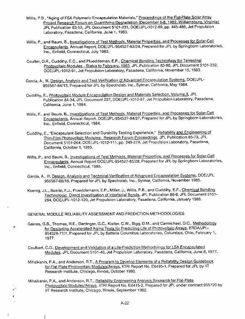
Willis,P.B.,"AgingofFSAPolymericEncapsulationMaterials,"Proceedinqs of the Flat-Plate Solar Array
Project Research Forum on Quantifyinq Deqradation (December 6-8, 1982, Williamsbura. Virainia),JPL Publication 83-52, JPL Document 5101-231, DOE/JPL-1012-89, pp. 445-486, Jet Propulsion
Laboratory, Pasadena, California, June 1, 1983.
Willis, P., and Baum, B., Investigations of Test Methods, Material Properties, and Processes for Solar-Cell
Encapsulants, Annual Report, DOE/JPL-954527-83/24, Prepared for JPL by Springborn Laboratories,
Inc., Enfield, Connecticut, July 1983.
Coulter, D.R., Cuddihy, E.C., and Plueddeman, E.P., Chemical Bondin.q Technoloqy for TerrestrialPhotovoltaic Modules - Status to February, 1983, JPL Publication 83-86, JPL Document 5101-232,
DOE/JPL-1012-91, Jet Propulsion Laboratory, Pasadena, California, November 15, 1983.
Garcia, A., Ill, Desiqn, Analysis and Test Verification of Advanced Encapsulation Systems, DOE/JPL-
955567-84/13, Prepared for JPL by Spectrolab, Inc., Sylmar, California, May 1984.
Cuddihy, E., Photovoltaic Module Encapsulation Desiqn and Materials Selection, Volume II, JPL
Publication 84-34, JPL Document 237, DOE/JPL-1012-97, Jet Propulsion Laboratory, Pasadena,
California, June 1, 1984.
Willis, P., and Baum, B., Investiqations of Test Methods, Material Properties, and Processes for Solar-Cell
Encapsulants, Annual Report, DOE/JPL-954527-84/27, Prepared for JPL by Springborn Laboratories,
Inc., Enfield, Connecticut, 1984.
Cuddihy, E., "Encapsulant Selection and Durability Testing Experience," Reliability and Enqineerinq ofThin-Film Photovoltaic Modules: Research Forum Proceedinqs, JPL Publication 85-73, JPL
Document 5101-264, DOE/JPL-1012-111, pp. 249-274, Jet Propulsion Laboratory, Pasadena,
California, October 1, 1985.
Willis, P., and Baum, B., Investi.qations of Test Methods, Material Properties, and Processes for Solar-Cell
Encapsulants, Annual Report DOE/JPL-954527-85/28, Prepared for JPL by Springborn Laboratories,
Inc., Enfield, Connecticut, 1985.
Garcia, A., Ill, Desiqn, Analysis and Technical Verification of Advanced Encapsulation Systems, DOE/JPL
955567-86/16, Prepared for JPL by Spectrolab, Inc., Sylmar, California, November 1985.
Koenig, J.L., Boerio, F.J., Plueddemann, E.P., Miller, J., Willis, P.B., and Cuddihy, E.F., Chemical Bondinq
Technoloqy: Direct Investigation of Interfacial Bonds, JPL Publication 86-6, JPL Document 5101-284, DOE/JPL-1012-120, Jet Propulsion Laboratory, Pasadena, California, January 1986.
GENERAL MODULE RELIABILITY ASSESSMENT AND PREDICTION METHODOLOGIES
Gaines, G.B., Thomas, R.E., Derringer, G.C., Kistler, C.W., Bigg, D.M., and Carmichael, D.C., Methodoloqy
for Designinq Accelerated Aqinq Tests for Predicting Life of Photovoltaic Arrays, ERDA/JPL-954328-77/1, Prepared for JPL by Battelle Columbus Laboratories, Columbus, Ohio, February 1,
1977.
Coulbert, C.D., Development and Validation of a Life-Prediction Methodology for LSA EncapsulatedModules, JPL Document 5101-40, Jet Propulsion Laboratory, Pasadena, California, June 8, 1977.
Mihalkanin, P.A., and Anderson, R.T., A Program to Develop Elements of a Reliability Desiqn Guidebook
for Flat Plate Photovoltaic Modules/Arrays, IITRI Report No. E6495-1, Prepared for JPL by liT
Research Institute, Chicago, Illinois, October 1980.
Mihalkanin, P.A., and Anderson, R.T., Reliability Enqineering Analysis Research for Flat-Plate
Photovoltaic Modules/Arrays, IITRI Report No. E6415-2, Prepared for JPL under contract 955720 by
liT Research Institute, Chicago, Illinois, September 1982.
A-22

Ross,R.G.,Jr.,"Time-IntegrationofEnvironmentalLoadsandStressesforCorrelatingFieldExposureandAcceleratedTesting,"Proceedings of the Flat-Plate Solar Array Project Research Forum onQ_antifyinq Deqradation (December 6-8, 1982, Williamsburg, Virginia), JPL Publication 83-52, JPL
Document 5101-231, DOE/JPL-1012-89, pp. 223-231, Jet Propulsion Laboratory, Pasadena, California,June 1, 1983.
Coulbert, C., The Application of Encapsulation Material Stabilitv Data to Photovoltaic Module Life
Assessment, JPL Publication 83-17, JPL Document 5101-224, DOE/JPL-1012-84, Jet Propulsion
Laboratory, Pasadena, California, April 1, 1983.
Otth, D.H., and Ross, R.G., Jr., "Assessing Photovoltaic Module Degradation and Lifetime from Long-Term
Environmental Tests," Proceedings of the 1983 Institute of Environmental Sciences 29th Annual
Meeting, Los Angeles, California, April 19-21, 1983, pp. 121-126.
Ross, R.G., Jr., "Reliability Research Toward 30-Year-Life Photovoltaic Modules," 1st International
Photovoltaic Science and Enqineerinq Conference - 1984, Kobe, Japan, November 13-16, 1984,
pp. 337-340, Secretariat of the International PVSEC-1, Tokyo, Japan.
A-23


Module Development and Test Experience
MODULE DEVELOPMENT AND TESTING OVERVIEW
Griffith, J., Dumas, L., and Hoffman, A.R., "Environmental Testing of Flat Plate Solar Cell Modules,"Proceedings of the Institute of Environmental Sciences Solar Seminar on Testinq Solar Energy
Materials and Systems, Gaithersburg, Maryland, May 22-24, 1978, pp. 1-11.
Hoffman, A.R., and Griffith, J.S., "Environmental Testing of Terrestrial Flat Plate Photovoltaic Modules,"
Proceedinqs of the 14th Intersociety Energy Conversion Engineering Conference, Boston,
Massachusetts, August 1979.
Runkle, L.D., and Dumas, L.N., "Progress in the Performance of Terrestrial Solar Cell Modules,"
Proceedings of the 1980 Annual Meetinq of the American Section of the International Solar Energy
Society, Phoenix, Arizona, June 1-6, 1980, pp. 1109-1113.
Smokier, M.I., and Runkle, L.D., "Experience in Design and Test of Terrestrial Solar-Cell Modules,"
Proceedings of the 1982 Annual Meeting of the American Section of the International Solar EnerqySociety, Houston, Texas, June 1-5, 1982.
Smokier, M.I., "Block V Module Development and Test Results," Proceedings of the 6th European
Photovoltaic Solar Energy Conference, London, U.K., April 15-19, 1985, pp. 370-376.
Smokier, M.I., Otth, D.H., and Ross, R.G., Jr., "The Block Program Approach to Photovoltaic Module
Development," Proceedinqs of the 18th IEEE Photovoltaic Specialists Conference, Las Vegas,
Nevada, October 21-25, 1985, pp. 1150-1158.
BLOCK PROCUREMENT AND DEVELOPMENTAL MODULE DESIGNS
Smokier, M., User Handbook for Block II Silicon Solar Cell Modules, JPL Document 5101-36, Jet
Propulsion Laboratory, Pasadena, California, October 15, 1977.
Smokier, M.I., User Handbook for Block Ill Silicon Solar Cell Modules, JPL Document 5101-82,
DOE/JPL-1012-79/6, Jet Propulsion Laboratory, Pasadena, California, February 1, 1979.
Smokier, M.I., and Runkle, L.D., "Experience in Design and Test of Terrestrial Solar-Cell Modules,"
Proceedings of the 1982 Annual Meeting of the American Section of the International Solar Enerqy
Society, Houston, Texas, June 1-5, 1982.
Smokier, M.I., User Handbook for Block IV Silicon Solar Cell Modules, JPL Publication 82-73, JPL
Document 5101-214, DOE/JPL-1012-75, Jet Propulsion Laboratory, Pasadena, California,
September 1, 1982.
Smokier, M.I., User Handbook for Block V Silicon Solar Cell Modules, JPL Document 5101-262, DOE/JPL-
1012-106, Jet Propulsion Laboratory, Pasadena, California, May 15, 1985.
Smokier, M.I., "Block V Module Development and Test Results," Proceedings of the 6th E.C. Photovoltaic
Solar Energy Conference, London, U.K., April 15-19, 1985, pp. 370-376.
Spitzer, M.B., Geoffroy, L.M., and Nowlan, M.J., "High Efficiency Flat-Plate Module Research,"
Proceedings of the 6th E.C. Photovoltaic Solar Energy Conference, London, U.K., April 15-19, 1985,
pp. 467-469.
Spitzer, M.B., Final Report, High-Efficiency Flat-Plate Modules, DOE/JPL-956641-86/1, Prepared for JPL
by Spire Corporation, Bedford, Massachusetts, July 1986.
pA F.. HOTA-25

QUALIFICATIONTESTRESULTS
Griffith,J.,Summary of Block I (46 kW) Module Testing, JPL Document 5101-27, Jet Propulsion
Laboratory, Pasadena, California, May 2, 1977.
Griffith, J., Environmental Testinq of Block II Solar Cell Modules, JPL Document 5101-98, DOE/JPL-
1012-79/1, Jet Propulsion Laboratory, Pasadena, California, January 1, 1979.
Griffith, J., "Qualification Test Results for DOE Solar Photovoltaic Flat Panel Procurement, PRDA 38,"
Proceedings of the 14th IEEE Photovoltaic Specialists Conference, San Diego, California, January
7-10, 1980, pp. 1290-1295.
Griffith, J., Environmental Testing of Block III Solar Cell Modules, JPL Document 5101-134, DOE/JPL-
1012-30, Jet Propulsion Laboratory, Pasadena, California, September 1, 1980.
FAILURE ANALYSIS TECHNIQUES AND RESULTS
Noel, G.T., Sliemers, F.A., Deringer, G.C., Wood, V.E., Wilkes, K.E., Gaines, G.B., and Carmichael, D.C.,Measurement Techniques and Instruments Suitable for Life-Prediction Testing of Photovoltaic
Array..s, DOE/JPL-954328-78/1, Prepared for JPL by Battelle Columbus Laboratories, Columbus, Ohio,
January 15, 1978.
Shumka, A., and Stern, K.H., "Some Failure Modes and Analysis Techniques for Terrestrial Solar CellModules," Proceedinqs of the 13th IEEE Photovoltaic Specialists Conference, Washington, D.C.,
June 5-8, 1978, pp. 824-834.
Miller, E.L., Shumka, A., and Gauthier, M., "A Laser Scanner for Solar Cell Evaluation and Failure
Analysis," Proceedinqs of the IEEE Advanced Techniques in Failure Analysis Symposium, LosAngeles, California, November 7, 1978.
Solar Cell Module Problem/Failure Reporting Procedure, JPL Document 5101-26, Revision A., Jet
Propulsion Laboratory, Pasadena, California, January 12, 1979.
Miller, E.L., Chern, S., and Shumka, A., "The Solar Cell Laser Scanner," Proceedinqs of the 15th IEEE
Photovoltaic Specialists Conference, Orlando, Florida, May 12-15, 1981, pp. 1126-1133.
Dumas, L.N., and Shumka, A., "Photovoltaic Module Reliability Improvement through Application Testing
and Failure Analysis," IEEE Transactions on Reliability, Vol. R-31, No. 3 (ISSN 0018-9529),
pp. 228-234, August 1982.
Kim, Q., and Shumka, A., "Discoloration of Poly (Vinyl Butyral) in Cells Exposed to Real and SimulatedSolar Environments," Solar Cells (12:4), pp. 345-352, September 1984.
Kim, Q., Shumka, A., and Trask, J., "Effects of Excitation Intensity on the Photocurrent Image of
Thin-Film Silicon Solar Modules (Abstract)," Bulletin of the American Physical Society (30:3),
Annual Meetinq, Baltimore, Maryland, March, 25-29, 1985, p. 335, American Physical Society.
FIELD TEST RESULTS
Jaffe, P., LSSA Field Test Activity System Description, JPL Document 5101-39, Jet Propulsion Laboratory,Pasadena, California, August 3, 1978.
Jaffe, P., LSA Field Test Annual Report, Auqust 1977 - Auqust 1978, JPL Document 5101-85, DOE/JPL-
1012-78/12, Jet Propulsion Laboratory, Pasadena, California, September 15, 1978.
Jaffe, P., LSA Field Test Annual Report August 1978 - August 1979, JPL Publication 80-5, JPL Document
5101-141, DOE/JPL-1012-38, Jet Propulsion Laboratory, Pasadena, California, December 15, 1979.
A-26

Jaffe,P.,LSA Field Test Annual Repqrt, August 1979 -Auqust 1980, JPL Publication 81-12, JPL
Document 5101-166, DOE/JPL-1012-52, Jet Propulsion Laboratory, Pasadena, California,December 30, 1980.
Hoffman, A., Jaffe, P., and Griffith, J., "Outdoor and Laboratory Testing of Photovoltaic Modules,"
Proceedinqs qf the 1981 Institute of Envirqnmental Sciences 27th Annual Technical Meeting, LosAngeles, California, May 4-7, 1981.
Dumas, L.N., and Shumka, A., "Field Failure Mechanisms for Photovoltaic Modules," Proceedinqs of the
15th IEEE Photovoltaic Specialists Conference, Orlando, Florida, May 12-15, 1981, pp_ 1091-1098.
Jaffe, P., Weaver, R.W., and Lee, R.H., FSA Field Te_t Annv01Repqrt, Auqust 1980 ° August 1981, JPL
Publication 81-99, JPL Document 5101-197, DOE/JPL-1012-59, Jet Propulsion Laboratory, Pasadena,California, December 15, 1981.
Maxwell, H.G., et al., FSA Field Test Report 1980-1982, JPL Publication 83-29, JPL Document 5101-215,DOE/JPL-1012-85, Jet Propulsion Laboratory, Pasadena, California, 1983.
Weaver, R.W., Lee, R.H., Meyer, J.D., and Runkle, L.D., FSA Field Test Annual Report: August 1981 -
January 1984, JPL Publication 84-52, JPL Document 5101-254, DOE/JPL-1012-100, Jet PropulsionLaboratory, Pasadena, California, August 15, 1984.
A-27


Summaries and Proceedings
AREA STATUS REPORTS AND PROGRESS SUMMARIES
Proceedings of the First Task Integration Meeting, JPL Document 5101-2, ERDAJJPL-1012-76/1, Jet
Propulsion Laboratory, Pasadena, California, January 1976.
Proceedinqs of the Second ProjeCt Integration Meeting, JPL Document 5101-5, ERDAJJPLo1012-76/4, Jet
Propulsion Laboratory, Pasadena, California, April 1976.
Proceedings of the Third Project Integration Meetinq, JPL Document 5101-8, ERDA/JPL-1012-76/7, Jet
Propulsion Laboratory, Pasadena, California, July 30, 1976.
Ross, R.G., Jr., "Large-Scale Procurement Design Requirements," Proceedinqs of the ERDA Semiannual
Solar Photovoltaic Proqram Review Meetinq, Orono, Maine, August 3-6, 1976, pp. 544-552.
Ross, R.G., Jr., "Silicon Solar Array Specifications and Near Term Performance Expectations," Proceedings
of U.S. Department of Energy Photovoltaic Systems and Applications Workshop, Reston, Virginia,
December 13-15, 1977, pp. 47-69.
Ross, R.G., Jr., "LSSA Engineering Status," Proceedinqs of the Semi-Annual Review Meeting, Silicon
Teqhn01ogy Programs - March 7-9, 1978, pp. 135-146, Solar Energy Research Institute, April 1978.
Dumas, L.N., "Operations Status: Large-Scale Module Procurement, Test and Evaluation," Proceedinqs of
the Semiannual Review Meeting, Silicon Technoloav Programs. March 7-9, 1978, pp. 147-149, Solar
Energy Research Institute, Golden, Colorado, April 1978.
Ross, R.G., Jr., "Terrestrial Silicon Array Field and Test Experience," Proceedings of the Department of
Energy Workshop on Stability of (Thin Filml Solar Cells and Materials, Washington, DC, June 4-8,1978, National Bureau of Standards.
Quarterly Report-11 for the Period October 1978-December 1978 and Proceedings of the 1lth Project
Integration Meeting, JPL Document 5101-109, DOE/JPL-1012-26, Jet Propulsion Laboratory,Pasadena, California, 1978.
Dumas, L.N., "Operations Status: Module Procurement, Test and Evaluation," Proceedings of the US DOE
Photovoltaic Technoloqy Development and Applications Program Review, CONF-781191, pp. 132-138,OAO Corporation, Arlington, Virginia, November 7-9, 1978.
Ross, R.G., Jr., "Array Engineering," Pr0ceedinqs of the U.S. DOE Semi-Annual P.roqram Review of
PhQtovoltaics Technology Development, Applications and Commercialization, CONF-791159,pp. 236-248, Pinehurst, North Carolina, November 5-7, 1979.
Proqress Report 14 for the Period Auqust 1979 to December 1979 and Proceedinqs of the 14th Project
Integration Meeting, JPL Publication 80-21, JPL Document 5101-142, DOE/JPL-1012-42, JetPropulsion Laboratory, Pasadena, California, 1980.
Electricity From Photovoltaic Solar Cells/Statvs of L0w-Cost Solar Array Project, JPL Document
5101-143, Jet Propulsion Laboratory, Pasadena, California, January 1980.
.Proqress Report 15 for the Period December 1979 to April 1980 and Proceedinqs of the 15th Project
Integration Meetincj, JPL Publication 80-27, JPL Document 5101-151, DOE/JPL-1012-44, Jet
Propulsion Laboratory, Pasadena, California, April 1980.
Dumas, L.N., and Ross, R.G., Jr., "Flat-Plate Technology: Status and Projected Availability," Proceedings
of the DOE Annual Photovoltaics Program Review for Technology and Market Development,
Hyannis, Massachusetts, April 28-30, 1980, p. 61-106, Conf-8004101, Jet Propulsion Laboratory,Pasadena, California.
_;,_E:_f_ G p_C_ 8t.A_'#X _KTr F_t -tV'_"A-29 PAGI_ |N,_NRONAI1Y BI.AI_
ProgressReport16forthePeriodApril1980to September1980andProceedinqsofthe16thProject.Integration Meeting, JPL Publication 80-100, JPL Document 5101-160, DOE/JPL-1012-51, Jet
Propulsion Laboratory, Pasadena, California, 1980.
Proqress Report 17 for the Period September 1980 to February 1981 and Proceedings of the 17t;h Project
Integration Meeting, JPL Publication 81-35, JPL Document 5101-172, DOE/JPL-1012-54, Jet
Propulsion Laboratory, Pasadena, California, 1981.
Proqress Report 1{} for the Period February 1981 to July 1981 and Proceedings of the 18th Project
Integration Meetinq, JPL Publication 81-94, JPL Document 5101-186, DOE/JPL-1012-58, JetPropulsion Laboratory, Pasadena, California, 1981.
Runkle, L.D., "Module Performance and Failure Analysis," Proceedings of the DOE Annual Photovoltaics
Proqram Review, Washington, D.C., December 7-9, 1981, CONF-811238 (DE82008857), pp. 265-287,
Jet Propulsion Laboratory, Pasadena, California, and Solar Energy Research Institute, Golden,Colorado.
Progress Report 19 for the Period July 1981 to November 1981 and Proceedinqs of the 19th ProjectIntegration Meetinq, JPL Publication 82-11, JPL Document 5101-194, DOE/JPL-1012-67, Jet
Propulsion Laboratory, Pasadena, California, 1982.
Progress Report 20 for the Period November 1981 to April 1982 and Proceedinqs of the 20th Project
Integration Meeting, JPL Publication 82-48, JPL Document 5101-209, DOE/JPL-1012-71, Jet
Propulsion Laboratory, Pasadena, California, 1982.
Progress Report 21 for the Period April 1982 to January 1983 and Proceedinqs of the 21st Project
Inteqration Meetinq, JPL Publication 83-48, JPL Document 5101-222, DOE/JPL-1012-88, Jet
Propulsion Laboratory, Pasadena, California, 1983.
Proqress Report 22 for the Period January 1983 to September 1983 and Proceedings of the 22nd ProjectInteclration Meetinq, JPL Publication 84-2, JPL Document 5101-242, DOE/JPL-1012-94, Jet
Propulsion Laboratory, Pasadena, California, 1984.
Ross, R.G., Jr., "Flat-Plate Solar Array Project (FSA) Reliability and Engineering Science Area,"
Abstracts, National Photovoltaics Programs Annual Review Meetinq, Kissimmee, Florida, April 30,
1984, SERI CP-211-2109 (DE84013003), pp. 105-118.
Progress Report 23 for the Period September 1983 to March 1984 and Proceedings of the 23rd ProjectInteqration Meeting, JPL Publication 84-47, JPL Document 5101-250, DOE/JPL-1012-99, Jet
Propulsion Laboratory, Pasadena, California, 1984.
Progress Report 24 for the Period March 1984 to October 1984 and Proceedinqs of the 24th Project
Integration Meetinq, JPL Publication 85-27, JPL Document 5101-259, DOE/JPL-1012-104, Jet
Propulsion Laboratory, Pasadena, California, 1985.
Progress Report 25 f.or the Period October 1984 to June 1985 and Proceedings of the 25th ProjectInteqration Meetinq, JPL Publication 86-4, JPL Document 5101-271, DOE/JPL-1012-119, Jet
Propulsion Laboratory, Pasadena, California, 1986.
Progress Report 26 for the Period July 1985 to April 1986 and Proceedings of the 26th Proiect
Integration Meetinq, JPL Publication 86-23, JPL Document 5101-286, DOE/JPL-1012-124, Jet
Propulsion Laboratory, Pasadena, California, April 1986.
WORKSHOP PROCEEDINGS
Flat Plate Photovoltai(; Module and Array Circuit Desiqn Optimization Workshop Proceedings, JPL
Internal Document 5101-170, Jet Propulsion Laboratory, Pasadena, California, May 19-20, 1980.
A-30

Royal,E.L.,andLathrop,J.W.,Determining Terrestrial Solar Cell Reliability - Proceedings of Workshop,
JPL Document 5101-163, Jet Propulsion Laboratory, Pasadena, California, November 1980.
Proceedings 0f the Flat-Pl_te S.olar Array Project Research Forum on Quantifying Degradation,
December 6-8, 1982, Williamsburg, VA, JPL Publication 83-52, JPL Document 5101-231,
DOE/JPL-1012-89, Jet Propulsion Laboratory, Pasadena, California, June 1, 1983.
Proceedings of the Flat-Plate Solar Array Project Research Forum on The Desiqn of Flat-Plate
Ph0tgvoltaic Arrays for Central Stations, December 5-8, 1983, Sacramento, California, JPL
Publication 84-44, JPL Document 5101-247, DOE/JPL-1012-98, Jet Propulsion Laboratory, Pasadena,California, 1984.
Ross, R.G., Jr., and Royal, E., Reliability and Engineerinq of Thin-Film Phot0voltaic Modules Research
Forum Proceedings, JPL Publication 85-73, JPL Document 5101-264, DOE/JPL-1012-111, JetPropulsion Laboratory, Pasadena, California, October 1, 1985.
A-31


APPENDIXB
Acquisition of References
Most of the references used in this report fall into one of four generic types: (1) JPL published
reports, (2) reports prepared for JPL by an outside contractor, (3) articles in the proceedings of
professional meetings, and (4) articles in professional journals.
JPL Published Reports
These reports nearly always contain an FSA project document number of the form 5101-xxx, and
may also contain a JPL Publication number (such as JPL Publication 83-52) and/or a Federal Government
sponsor number in the form of DOE/JPL-1012-xx. Only those reports containing a JPL Publicationnumber can be easily obtained from JPL. These can be obtained from:
Jet Propulsion LaboratoryDocumentation and Materiel Division4800 Oak Grove Dr.
Pasadena, CA 91109
JPL reports containing the Federal Government sponsor number DOE/JPL-1012-xx can be obtainedfrom:
U.S. Department of CommerceNational Technical Information Service
5285 Port Royal RoadSpringfield, VA 22161
or U.S. Department of EnergyTechnical Information Center
Publication Request SectionP.O. Box 62
Oak Ridge, TN 37831
JPL reports without a JPL publication number or Federal Government sponsor number are internal JPL
reports. They are sometimes available from the Documentation and Materiel Division, which determines
their releasability with the author's organization, assuming copies are still in print.
JPL Contractor Reports
These reports are available from the National Technical Information Service (NTIS) at the
Springfield, Virginia, address given above, using the Federal Government sponsor number (D©E/JPL9xxxxx-xx) associated with the reference. They are generally not available from either JPL or the
contractor who prepared the report.
B-1

Techni(;:al Conference Proceedings
Several technical conferences have been widely used for publishing papers due to the relevance of
their scope, their rapid turn-around, and their wide availability. Key conference proceedings and theirassociated publishers include:
(1) IEEE Photovoltaic Specialists Conference
Institute of Electrical and Electronic Engineers, Inc.345 E. 47th Street
New York, NY 10017
(2) American Solar Energy Society (ASES)
Formerly American Section of the International Solar EnergySociety (AS/ISES)Publications Director
2030 17th Street
Boulder, CO 80302
(3) Institute of Environmental Sciences (IES)
940 E. Northwest HighwayMt. Prospect, IL 60056
(4) Commission of European Communities (EC)
Photovoltaic Solar Energy Conference
D. Reidel Publishing CompanyP.O. Box 17, 3300 AA Dordrecht, Holland
(or in U.S.)Kluwer Boston, Inc.
190 Old Denby St.
Hingham, MA 02043
(5) Intersociety Energy Conversion Engineering Conference
Published by American Chemical Society1155 Sixteenth St., NW
Washington, D.C. 20036
(6) American Institute of Aeronautics and Astronautics (AIAA)
AIAA Library750 3rd Ave.
New York, NY 10017
(7) American Society of Mechanical Engineers (ASME)United Engineering Center345 E. 47th St.
New York, NY 10017
Professional Journals
These are widely available from technical libraries.
B-2

APPENDIXC
Glossary
AC
AR
ASTM
CRT
Cz
DC
DOE
EVA
FSA
FZ
GE
IEEE
I-V
JPL
LAPSS
LSSA
MIT
alternating current
antireflective
American Society for Testing andMaterials
cathode ray tube
Czochralski
direct current
U.S. Department of Energy
ethylene vinyl acetate
Flat-Plate Solar Array (Project)
float zone
General Electric
Institute of Electrical and ElectronicsEngineers, Inc,
current-voltage
Jet Propulsion Laboratory
Large-Area Pulsed Solar Simulator
Low-Cost Silicon Solar Array (Project)
Massachusetts Institute of Technology
MOV
MPFA
NASA
NEC
NOCT
PRDA
PV
PVB
PV-T
QA
SERI
SMUD
SOLMET
UL
UV
metal-oxide varistor
Module Performance and Failure
Analysis
National Aeronautics and SpaceAdministration
National Electrical Code
Nominal Operating Cell Temperature
Program Research and DevelopmentAnnouncement
photovoltaic (s)
polyvinyl butyral
photovoltaic/thermal
quality assurance
Solar Energy Research Institute
Sacramento Municipal Utility District
Solar Radiation-Surface MeteorologicalObservations
Underwriters Laboratories
ultraviolet
C-1


Prepared by the Jet Propulsion Laboratory, California Institute of Technology,
for the U.S. Department of Energy through an agreement with the National
Aeronautics and Space Administration.
The JPL Flat-Plate Solar Array Project is sponsored by the U.S. Department of
Energy and is part of the National Photovoltaics Program to initiate a major
effort toward the development of cost-competitive solar arrays.
This report was prepared as an account of work sponsored by an agency of the
United States Government. Neither the United States Government nor any
agency thereof, nor any of their employees, makes any warranty, express or
implied, or assumes any legal liability or responsibility for the accuracy, com-
pleteness, or usefulness of any information, apparatus, product, or process
disclosed, or represents that its use would not infringe privately owned rights.
Reference herein to any specific commercial product, process, or service by trade
name, trademark, manufacturer, or otherwise, does not necessarily constitute or
imply its endorsement, recommendation, or favoring by the United States
Government or any agency thereof. The views and opinions of authors expressed
herein do not necessarily state or reflect those of the United States Government
or any agency thereof.


More Technology Advancements
Dendritic web silicon ribbons are grown to solar-cell
thickness. Progress is shown by experimental ribbons
grown in 1976 and 1978 and a ribbon grown in aWestinghouse Electric Corporation pilot plant.
JThe edge-defined film-fed growth silicon ribbons are
grown to solar-cell thickness. A DOE/FSA-sponsoredresearch ribbon grown in 1976 is shown next to a
nine-sided ribbon grown in a Mobil Solar Energy
Corporation funded configuration.
1980
INGOT GROWNUSING SILICON MELT
REPLENISHMENT
1968-73
Czochralski silicon crystals as grown are
sawed into thin circular wafers. (Support for
this effort was completed in 1981.)
"_ _-- I ", _._ ",--_'l GLASS (STRUCTURAL)
SPACER
POTTANT
-. _l_ _ SOLAR CELLSINTERCONNECTED
SPACERJ 'S,AL .......... POTTANT
GASKET _' BACK COVER FILM
(COMPOSITEI
Typical superstrate module design is shown with the
electrically interconnected solar cells embedded in a
laminate that is structurally supported by glass,
Materials and processes suitable for mass production
have been developed using this laminated design.
Prototype modules have passed UL 790 Class A
burning brand tests which are more severe thanthis spread of flame test.
A 15,2% efficiency prototype module (21 x 36 in.)
was made by Spire Corp. using float-zone sihcon
wafers. Recently, similarly efficient modules werefabricated from Czochralski silicon wafers.

Photovoltaic Applications
1975
U.S. Coast Guard buoy
with photovoltaic-powered
navigational light.
Photovoltaic-powered corrosion protection
of underground pipes and wells.
Later...
House in Carlisle, Massachusetts, with a 7.3-kW
photovoltaic rooftop array. Excess photovoltaic-
generated power is sold to the utility. Power isautomatically supplied by the utility as needed.
1985
A 28-kW array of solar cells for crop irngation
during summer, and crop drying during winter
(a DOE�University of Nebraska cooperative prolect).
1.2 MW of photovoltaic peaking-power generationcapacity, for the Sacramento Municipal Utility District.
(The 8 ._ I6 fl panels are mounted on a north-south
axis for tracking the sun.)