Embed Size (px)
Citation preview
TREBALL FI DE GRAU
Grau en Enginyeria de la Energia
ELECTRIFICATION PROJECT IN A BOX FACTORY
Volume II
Electric calculations of the installation
Autor: Nil Domenech Ruiz Director: Rodolfo Oseira Goas Convocatòria: Junio 2017

Electrification project in a box factory
i
General index
1. MEMORY 2. ELECTRIC CALCULATIONS OF THE INSTALLATION 3. PLANES 4. BUDGET
Memoria
ii
Electric calculations index
2. ELECTRIC CALCULATIONS OF THE INSTALLATION ______________________ 15
2.1. Used formulas ........................................................................................................ 15
2.1.1. Three-phase system .............................................................................................. 15
2.1.2. Monophasic system .............................................................................................. 15
2.1.3. Formula electrical conductivity ............................................................................. 16
2.1.4. Overload formulas ................................................................................................ 17
2.1.5. Formula reactive energy compensation ............................................................... 17
2.1.6. Formula short circuit ............................................................................................. 18
2.1.7. Formula Bus bar .................................................................................................... 21
2.1.8. Formula ground resistance ................................................................................... 22
2.2. General panel of control and protection .............................................................. 24
2.2.1. Power demand ...................................................................................................... 24
2.2.2. Bus Bar calculations: Transformation Station ...................................................... 24
2.2.3. Calculation line: CT ................................................................................................ 25
2.2.4. Calculation line: General distribution panel ......................................................... 26
2.2.5. Calculation line: TS GROUP ................................................................................... 27
2.2.6. Calculation line: SWITCHBOARD ........................................................................... 27
2.2.7. Calculation line: LIGHTING TS ............................................................................... 28
2.2.8. Calculation line: METER PLUG .............................................................................. 29
2.2.9. Bus Bar calculations: General Panel ..................................................................... 30
2.3. Sub-panel General Panel ....................................................................................... 31
2.3.1. Power demand ...................................................................................................... 31
2.3.2. Capacitor bank calculation .................................................................................... 32
2.3.3. Calculation line: Capacitor bank ........................................................................... 33
2.3.4. Calculation line: PUMP01 ..................................................................................... 34
2.3.1. Calculation line: PURIFICATION ............................................................................ 34
2.3.2. Calculation line: SP-ELE ......................................................................................... 35
2.3.3. Calculation line: SP-WEATHER .............................................................................. 36
2.3.4. Calculation line: SP-COMP .................................................................................... 37
2.3.5. Calculation line: SP-WASEHOUSE ......................................................................... 38
2.3.6. Calculation line: SP-OFILOG .................................................................................. 39
2.3.7. Calculation line: SP-EMBA244 .............................................................................. 39
2.3.8. Calculation line: SP-EMBA170 .............................................................................. 40
2.3.9. Calculation line: SP-PROD1 ................................................................................... 41
2.3.10. Calculation line: SP-WORKSHOP ........................................................................... 42

Electrification project in a box factory
iii
2.3.11. Calculation line: SP-PROD2 ................................................................................... 43
2.3.12. Calculation line: SP-BOBST ................................................................................... 44
2.3.13. Calculation line: SP-TRANSFER ............................................................................. 45
2.3.14. Calculation line: SP-EXIT ....................................................................................... 46
2.3.15. Calculation line: SP-SUCTION ............................................................................... 47
2.3.16. Calculation line: SP-TOILETS ................................................................................. 48
2.3.17. Calculation line: SP-OFFICES ................................................................................. 49
2.3.18. Calculation line: SP-INFORMATICS ....................................................................... 50
2.3.19. Calculation line: SP-FIREPROT .............................................................................. 51
2.3.20. Calculation line: SP-VENTILATION ........................................................................ 52
2.3.21. Calculation line: SP-LIGHTING .............................................................................. 53
2.3.22. Calculation line: SP-DINING .................................................................................. 54
2.3.23. Calculation line: SP-DYE ........................................................................................ 55
2.3.24. Calculation line: SP-PRESS .................................................................................... 56
2.4. Sub-panel SP-WEATHER ......................................................................................... 57
2.4.1. Power demand ..................................................................................................... 57
2.4.2. Calculation line: CP-GEOTHERMAL ...................................................................... 57
2.4.3. Calculation line: GAS BOILER ................................................................................ 58
2.4.4. Calculation line: LT ................................................................................................ 59
2.4.5. Calculation line: LT-01 .......................................................................................... 59
2.4.6. Calculation line: EMERGENCY .............................................................................. 60
2.4.7. Calculation line: PUMPS-02 .................................................................................. 61
2.4.8. Calculation line: OFFICES PUMP ........................................................................... 61
2.4.9. Calculation line: DRESSING ROOM PUMP ............................................................ 62
2.4.10. Calculation line: ACS PUMP .................................................................................. 63
2.4.11. Calculation line: AIRCOND .................................................................................... 64
2.4.12. Calculation line: PUMPS-01 .................................................................................. 65
2.4.13. Calculation line: FACTORY PUMP ......................................................................... 65
2.4.14. Calculation line: WAREHOUSE PUMP .................................................................. 66
2.4.15. Calculation line: CONTROLPUMPS ....................................................................... 67
2.4.16. Bus Bar calculations: SP-WEATHER ...................................................................... 68
2.5. Sub-panel SP-COMP ............................................................................................... 69
2.5.1. Power demand ..................................................................................................... 69
2.5.2. Calculation line: COM01 ....................................................................................... 69
2.5.3. Calculation line: COM03 ....................................................................................... 70
2.5.4. Calculation line: DRY01 ......................................................................................... 71
2.5.5. Calculation line: COMP-2 ...................................................................................... 72

Memoria
iv
2.5.6. Calculation line: LT01 ............................................................................................ 72
2.5.7. Calculation line: EMERGENCY ............................................................................... 73
2.5.8. Calculation line: COM02 ....................................................................................... 74
2.5.9. Calculation line: SUCTION ..................................................................................... 75
2.5.10. Calculation line: PLUG01 ....................................................................................... 75
2.5.11. Calculation line: SERVICE BOXES ........................................................................... 76
2.5.12. Calculation line: SW V P ........................................................................................ 77
2.5.13. Bus Bar calculations: SP-COMP ............................................................................. 78
2.6. Sub-panel SP-WAREHOUSE ................................................................................... 79
2.6.1. Power demand ...................................................................................................... 79
2.6.2. Calculation line: WAREHOUSE 0 ........................................................................... 79
2.6.3. Calculation line: CBA01 ......................................................................................... 80
2.6.4. Calculation line: CBA02 ......................................................................................... 81
2.6.5. Calculation line: WAREHOUSE 1 ........................................................................... 81
2.6.6. Calculation line: CBA3 ........................................................................................... 82
2.6.7. Calculation line: CBA4 ........................................................................................... 83
2.6.8. Calculation line: WAREHOUSE 2 ........................................................................... 83
2.6.9. Calculation line: DOOR01 ...................................................................................... 84
2.6.10. Calculation line: DOOR02 ...................................................................................... 85
2.6.11. Calculation line: WAREHOUSE 3 ........................................................................... 85
2.6.12. Calculation line: DOOR03 ...................................................................................... 86
2.6.13. Calculation line: DOOR04 ...................................................................................... 87
2.6.14. Calculation line: WAREHOUSE 4 ........................................................................... 87
2.6.15. Calculation line: LP01 ............................................................................................ 88
2.6.16. Calculation line: LP02 ............................................................................................ 89
2.6.17. Calculation line: WAREHOUSE 5 ........................................................................... 90
2.6.18. Calculation line: AER01 ......................................................................................... 90
2.6.19. Calculation line: AER02 ......................................................................................... 91
2.6.20. Calculation line: AER03 ......................................................................................... 92
2.6.21. Calculation line: SB ................................................................................................ 92
2.6.22. Calculation line: BRIDGE ....................................................................................... 93
2.6.23. Calculation line: BACKUP ...................................................................................... 94
2.6.24. Bus Bar calculations: SP-WAREHOUSE ................................................................. 95
2.7. Sub-panel SP-OFILOG............................................................................................. 96
2.7.1. Power demand ...................................................................................................... 96
2.7.2. Calculation line: LT ................................................................................................ 96
2.7.3. Calculation line: LT01 ............................................................................................ 97
Electrification project in a box factory
v
2.7.4. Calculation line: EMERGENCY .............................................................................. 97
2.7.5. Calculation line: PLUGS01 .................................................................................... 98
2.7.6. Calculation line: PLUGS 1 ...................................................................................... 99
2.7.7. Calculation line: PLUGS 2 ...................................................................................... 99
2.7.8. Calculation line: PLUGS 3 .................................................................................... 100
2.7.9. Calculation line: PLUGS02 .................................................................................. 101
2.7.10. Calculation line: PLUGS 4 .................................................................................... 101
2.7.11. Calculation line: CLI01 ........................................................................................ 102
2.7.12. Calculation line: CLI02 ........................................................................................ 103
2.7.13. Bus Bar calculations: SP-WEATHER .................................................................... 103
2.8. Sub-panel SP-EMBA244 ....................................................................................... 104
2.8.1. Power demand ................................................................................................... 104
2.8.2. Calculation line: BCR01 ....................................................................................... 105
2.8.3. Calculation line: EMBA244-1 .............................................................................. 105
2.8.4. Calculation line: TIER01 ...................................................................................... 106
2.8.5. Calculation line: CCM01 ..................................................................................... 107
2.8.6. Calculation line: PALLMAC.................................................................................. 108
2.8.7. Calculation line: EMBA244-2 .............................................................................. 108
2.8.8. Calculation line: GH01 ........................................................................................ 109
2.8.9. Calculation line: CHAIN01 ................................................................................... 110
2.8.10. Calculation line: CHAIN02 ................................................................................... 110
2.8.11. Calculation line: EMBA244-3 .............................................................................. 111
2.8.12. Calculation line: DIS01 ........................................................................................ 112
2.8.13. Calculation line: ROLL01 ..................................................................................... 112
2.8.14. Calculation line: ROLL02 ..................................................................................... 113
2.8.15. Calculation line: FEEDER ..................................................................................... 114
2.8.16. Bus Bar calculations: SP-EMBA244 .................................................................... 115
2.9. Sub-panel SP-EMA170 ......................................................................................... 116
2.9.1. Power demand ................................................................................................... 116
2.9.2. Calculation line: BCR01 ....................................................................................... 116
2.9.3. Calculation line: EMBA170 1 .............................................................................. 117
2.9.4. Calculation line: ELEVATOR ................................................................................ 118
2.9.5. Calculation line: TIER01 ...................................................................................... 118
2.9.6. Calculation line: ROBOT ...................................................................................... 119
2.9.7. Calculation line: EMBA170 2 .............................................................................. 120
2.9.8. Calculation line: HYDELEVATOR01 ..................................................................... 121
2.9.9. Calculation line: ROLL01 ..................................................................................... 121

Memoria
vi
2.9.10. Calculation line: HYDELEVATOR02 ...................................................................... 122
2.9.11. Calculation line: FEEDER ..................................................................................... 123
2.9.12. Calculation line: EMBA170 3 ............................................................................... 123
2.9.13. Calculation line: ROLL02 ..................................................................................... 124
2.9.14. Calculation line: ROLL03 ..................................................................................... 125
2.9.15. Calculation line: ROLL04 ..................................................................................... 125
2.9.16. Bus Bar calculations: SP-EMBA170 ..................................................................... 126
2.10. Sub-panel SP-PROD1 ........................................................................................... 127
2.10.1. Power demand .................................................................................................... 127
2.10.2. Calculation line: STR01 ........................................................................................ 128
2.10.3. Calculation line: STR02 ........................................................................................ 128
2.10.4. Calculation line: BALER01 ................................................................................... 129
2.10.5. Calculation line: BALER02 ................................................................................... 130
2.10.6. Calculation line: SEM01 ...................................................................................... 131
2.10.7. Calculation line: BIMA01 ..................................................................................... 131
2.10.8. Calculation line: PAMA01 ................................................................................... 132
2.10.9. Calculation line: EBR01 ....................................................................................... 133
2.10.10. Calculation line: ROLL01 ..................................................................................... 134
2.10.11. Calculation line: ROLL02 ..................................................................................... 135
2.10.12. Calculation line: ROLL03 ..................................................................................... 135
2.10.13. Calculation line: TRIFASIC PLUGS ........................................................................ 136
2.10.14. Bus Bar calculations: SP-PROD1 .......................................................................... 137
2.11. Sub-panel SP-WORKSHOP ................................................................................... 138
2.11.1. Power demand .................................................................................................... 138
2.11.2. Calculation line: LT1 ............................................................................................ 138
2.11.3. Calculation line: LT01 .......................................................................................... 139
2.11.4. Calculation line: PLUGS ....................................................................................... 140
2.11.5. Calculation line: EMERGENCY ............................................................................. 140
2.11.6. Calculation line: SERVICEBOX01 ......................................................................... 141
2.11.7. Calculation line: SERVICEBOX02 ......................................................................... 142
2.11.8. Calculation line: SERVICE BOXES ......................................................................... 142
2.11.9. Calculation line: AER01 ....................................................................................... 143
2.11.10. Bus Bar calculations: SP-WORKSHOP ................................................................. 144
2.12. Sub-panel SP-PROD2 ........................................................................................... 145
2.12.1. Power demand .................................................................................................... 145
2.12.2. Calculation line: DC01 ......................................................................................... 146
2.12.3. Calculation line: DC02 ......................................................................................... 146

Electrification project in a box factory
vii
2.12.4. Calculation line: ST01 ......................................................................................... 147
2.12.5. Calculation line: SHEAR01 .................................................................................. 148
2.12.6. Calculation line: SM01 ........................................................................................ 149
2.12.7. Calculation line: CR01 ......................................................................................... 149
2.12.8. Calculation line: CR02 ......................................................................................... 150
2.12.9. Calculation line: PLUGS....................................................................................... 151
2.12.10. Calculation line: PROD2-1................................................................................... 152
2.12.11. Calculation line: DOOR01 ................................................................................... 152
2.12.12. Calculation line: DOOR02 ................................................................................... 153
2.12.13. Calculation line: DOOR03 ................................................................................... 154
2.12.14. Bus Bar calculations: SP-PROD2 ......................................................................... 155
2.13. Sub-panel SP-BOBST ............................................................................................ 156
2.13.1. Power demand ................................................................................................... 156
2.13.2. Calculation line: DC01 ......................................................................................... 156
2.13.3. Calculation line: BOBST1 .................................................................................... 157
2.13.4. Calculation line: PE01 ......................................................................................... 157
2.13.5. Calculation line: ROLLER ..................................................................................... 158
2.13.6. Calculation line: PLUGS....................................................................................... 159
2.13.7. Calculation line: LT01 .......................................................................................... 160
2.13.8. Bus Bar calculations: SP-BOBST .......................................................................... 160
2.14. Sub-panel SP-TRANSFER ...................................................................................... 161
2.14.1. Power demand ................................................................................................... 161
2.14.2. Calculation line: TRANSFER0 .............................................................................. 162
2.14.3. Calculation line: ROLLER04 ................................................................................. 163
2.14.4. Calculation line: ROLLER05 ................................................................................. 163
2.14.5. Calculation line: TRANSFER1 .............................................................................. 164
2.14.6. Calculation line: TRA01 ....................................................................................... 165
2.14.7. Calculation line: TRA02 ....................................................................................... 165
2.14.8. Calculation line: TRA03 ....................................................................................... 166
2.14.9. Calculation line: TRANSFER2 .............................................................................. 167
2.14.10. Calculation line: TRA04 ....................................................................................... 168
2.14.11. Calculation line: CAR01....................................................................................... 168
2.14.12. Calculation line: CAR02....................................................................................... 169
2.14.13. Calculation line: TRANSFER3 .............................................................................. 170
2.14.14. Calculation line: ROLLER01 ................................................................................. 170
2.14.15. Calculation line: ROLLER02 ................................................................................. 171
2.14.16. Calculation line: ROLLER03 ................................................................................. 172
Memoria
viii
2.14.17. Bus Bar calculations: SP-TRANSFER .................................................................... 172
2.15. Sub-panel SP-EXT ................................................................................................. 173
2.15.1. Power demand .................................................................................................... 173
2.15.2. Calculation line: DOOR01 .................................................................................... 174
2.15.3. Calculation line: DOOR02 .................................................................................... 174
2.15.4. Calculation line: BACKUP .................................................................................... 175
2.15.5. Bus Bar calculations: SP-EXT ............................................................................... 176
2.16. Sub-panel SP-SUCTION ........................................................................................ 177
2.16.1. Power demand .................................................................................................... 177
2.16.2. Calculation line: SP-SUC-VENT ............................................................................ 177
2.16.3. Calculation line: FTM1500 .................................................................................. 178
2.16.4. Calculation line: SUCTION 1 ................................................................................ 179
2.16.5. Calculation line: VAL-VEOLAR1500 ..................................................................... 180
2.16.6. Calculation line: SWITCHBOARD ......................................................................... 180
2.16.7. Calculation line: SUCTION 2 ................................................................................ 181
2.16.8. Calculation line: PLC ............................................................................................ 182
2.16.9. Calculation line: SIGNAL 24V .............................................................................. 182
2.16.10. Calculation line: BACKUP1 .................................................................................. 183
2.16.11. Calculation line: BACKUP2 .................................................................................. 184
2.16.12. Bus Bar calculations: SP-SUCTION ...................................................................... 184
2.17. Sub-panel SP-SUC-VENT ...................................................................................... 185
2.17.1. Power demand .................................................................................................... 185
2.17.2. Calculation line: CUT ........................................................................................... 186
2.17.3. Calculation line: SWITCHBOARD ......................................................................... 186
2.17.4. Calculation line: BACKUP1 .................................................................................. 187
2.17.5. Calculation line: BACKUP2 .................................................................................. 188
2.17.6. Bus Bar calculations: SP-SUC-VENT .................................................................... 189
2.18. Sub-panel SP-TOILETS .......................................................................................... 190
2.18.1. Power demand .................................................................................................... 190
2.18.2. Calculation line: TOILETS 1 .................................................................................. 190
2.18.3. Calculation line: LT01 .......................................................................................... 191
2.18.4. Calculation line: LT02 .......................................................................................... 192
2.18.5. Calculation line: EMERGENCY ............................................................................. 192
2.18.6. Calculation line: TOILETS 2 .................................................................................. 193
2.18.7. Calculation line: HDRY01..................................................................................... 194
2.18.8. Calculation line: HDRY02..................................................................................... 194
2.18.9. Calculation line: TOILETS 3 .................................................................................. 195
Electrification project in a box factory
ix
2.18.10. Calculation line: HDRY03 .................................................................................... 196
2.18.11. Calculation line: HDRY04 .................................................................................... 196
2.18.12. Calculation line: AIR01 ........................................................................................ 197
2.18.13. Calculation line: TOILETS 4 ................................................................................. 198
2.18.14. Calculation line: BACKUP1 .................................................................................. 198
2.18.15. Calculation line: BACKUP2 .................................................................................. 199
2.18.16. Calculation line: AUTDOOR ................................................................................ 200
2.18.17. Bus Bar calculations: SP-TOILETS........................................................................ 200
2.19. Sub-panel SP-OFFICES .......................................................................................... 201
2.19.1. Power demand ................................................................................................... 201
2.19.2. Calculation line: OFFICES 1 ................................................................................. 202
2.19.3. Calculation line: LT01 .......................................................................................... 203
2.19.4. Calculation line: LT02 .......................................................................................... 204
2.19.5. Calculation line: EMERGENCY ............................................................................ 204
2.19.6. Calculation line: OFFICES 2 ................................................................................. 205
2.19.7. Calculation line: LT03 .......................................................................................... 206
2.19.8. Calculation line: LT04 .......................................................................................... 206
2.19.9. Calculation line: LT05 .......................................................................................... 207
2.19.10. Calculation line: EMERGENCY ............................................................................ 208
2.19.11. Calculation line: OFFICES 3 ................................................................................. 208
2.19.12. Calculation line: PLUG01 .................................................................................... 209
2.19.13. Calculation line: PLUG02 .................................................................................... 210
2.19.14. Calculation line: PLUG03 .................................................................................... 210
2.19.15. Calculation line: CLI05 ........................................................................................ 211
2.19.16. Calculation line: OFFICES 4 ................................................................................. 212
2.19.17. Calculation line: PLUG04 .................................................................................... 213
2.19.18. Calculation line: PLUG05 .................................................................................... 213
2.19.19. Calculation line: PLUG06 .................................................................................... 214
2.19.20. Calculation line: OFFICES 5 ................................................................................. 215
2.19.21. Calculation line: CLI01 ........................................................................................ 215
2.19.22. Calculation line: CLI02 ........................................................................................ 216
2.19.23. Calculation line: CLI03 ........................................................................................ 217
2.19.24. Calculation line: CLI04 ........................................................................................ 217
2.19.25. Calculation line: DOOR ....................................................................................... 218
2.19.26. Bus Bar calculations: SP-OFFICES ....................................................................... 219
2.20. Sub-panel SP-INFORMATICS ................................................................................ 220
2.20.1. Power demand ................................................................................................... 220

Memoria
x
2.20.2. Calculation line: PLUGSAI 1 ................................................................................. 221
2.20.3. Calculation line: PSAI11 ...................................................................................... 222
2.20.4. Calculation line: PSAI12 ...................................................................................... 222
2.20.5. Calculation line: PLUGSAI 2 ................................................................................. 223
2.20.6. Calculation line: PSAI10 ...................................................................................... 224
2.20.7. Calculation line: PSAI01 ...................................................................................... 224
2.20.8. Calculation line: PLUGSAI 3 ................................................................................. 225
2.20.9. Calculation line: PSAI02 ...................................................................................... 226
2.20.10. Calculation line: PSAI03 ...................................................................................... 226
2.20.11. Calculation line: PLUGSAI 4 ................................................................................. 227
2.20.12. Calculation line: PSAI04 ...................................................................................... 228
2.20.13. Calculation line: PSAI05 ...................................................................................... 228
2.20.14. Calculation line: PLUGSAI 5 ................................................................................. 229
2.20.15. Calculation line: PSAI06 ...................................................................................... 230
2.20.16. Calculation line: PSAI07 ...................................................................................... 230
2.20.17. Calculation line: PLUGSAI 6 ................................................................................. 231
2.20.18. Calculation line: PSAI08 ...................................................................................... 232
2.20.19. Calculation line: PSAI09 ...................................................................................... 232
2.20.20. Calculation line: AIRCON01 ................................................................................. 233
2.20.21. Calculation line: RACK 1 ...................................................................................... 234
2.20.22. Calculation line: RACK COM1 .............................................................................. 234
2.20.23. Calculation line: RACK SER1 ................................................................................ 235
2.20.24. Calculation line: RACK 2 ...................................................................................... 236
2.20.25. Calculation line: RACK COM2 .............................................................................. 236
2.20.26. Calculation line: RACK SER2 ................................................................................ 237
2.20.27. Calculation line: CCTV ......................................................................................... 238
2.20.28. Calculation line: SP-SAILOG................................................................................. 238
2.20.29. Calculation line: SP-RACK B ................................................................................. 239
2.20.30. Bus Bar calculations: SP-INFORMATICS .............................................................. 240
2.21. Sub-panel SP-SAILOG ........................................................................................... 241
2.21.1. Power demand .................................................................................................... 241
2.21.2. Calculation line: SAILOG ...................................................................................... 241
2.21.3. Calculation line: PSAI01 ...................................................................................... 242
2.21.4. Calculation line: PSAI02 ...................................................................................... 242
2.21.5. Calculation line: PSAI03 ...................................................................................... 243
2.21.6. Bus Bar calculations: SP-SAILOG ......................................................................... 244
2.22. Sub-panel SP-RACKB ............................................................................................ 245

Electrification project in a box factory
xi
2.22.1. Power demand ................................................................................................... 245
2.22.2. Calculation line: RACKB 1 ................................................................................... 245
2.22.3. Calculation line: PRACKB01 ................................................................................ 246
2.22.4. Calculation line: PRACKB02 ................................................................................ 246
2.22.5. Calculation line: RACKB 2 ................................................................................... 247
2.22.6. Calculation line: PRACKB03 ................................................................................ 248
2.22.7. Calculation line: PRACKB04 ................................................................................ 248
2.22.8. Bus Bar calculations: SP-RACKB .......................................................................... 249
2.23. Sub-panel SP-FIREPROT ....................................................................................... 250
2.23.1. Power demand ................................................................................................... 250
2.23.2. Calculation line: FIREPROT 1 .............................................................................. 250
2.23.3. Calculation line: LT01 .......................................................................................... 251
2.23.4. Calculation line: EMERGENCY ............................................................................ 252
2.23.5. Calculation line: PLUG ........................................................................................ 252
2.23.6. Calculation line: POWER GRILL ........................................................................... 253
2.23.7. Calculation line: CHLORINATION ........................................................................ 254
2.23.8. Calculation line: AEROTHERM ............................................................................ 255
2.23.9. Calculation line: RESISTANCE TANK ................................................................... 256
2.23.10. Bus Bar calculations: SP-FIREPROT ..................................................................... 256
2.24. Sub-panel SP-VENTILATION ................................................................................. 257
2.24.1. Power demand ................................................................................................... 257
2.24.2. Calculation line: CONTROL VENTILATION .......................................................... 258
2.24.3. Calculation line: EXTRACT01............................................................................... 259
2.24.4. Calculation line: EXTRACT02............................................................................... 259
2.24.5. Calculation line: EXTRACT03............................................................................... 260
2.24.6. Calculation line: EXTRACT04............................................................................... 261
2.24.7. Calculation line: EXTRACT05............................................................................... 262
2.24.8. Calculation line: EXTRACT06............................................................................... 263
2.24.9. Calculation line: BACKUP .................................................................................... 264
2.24.10. Calculation line: BACKUP .................................................................................... 264
2.24.11. Calculation line: BACKUP .................................................................................... 265
2.24.12. Bus Bar calculations: SP-VENTILATION .............................................................. 266
2.25. Sub-panel SP-LIGHTING ....................................................................................... 267
2.25.1. Power demand ................................................................................................... 267
2.25.2. Calculation line: LIGHTING1 ............................................................................... 268
2.25.3. Calculation line: LT01 .......................................................................................... 269
2.25.4. Calculation line: LT03 .......................................................................................... 269
Memoria
xii
2.25.5. Calculation line: EMERGENCY01 ......................................................................... 270
2.25.6. Calculation line: LIGHTING2 ................................................................................ 271
2.25.7. Calculation line: LT02 .......................................................................................... 271
2.25.8. Calculation line: LT04 .......................................................................................... 272
2.25.9. Calculation line: LT06 .......................................................................................... 273
2.25.10. Calculation line: LIGHTING3 ................................................................................ 273
2.25.11. Calculation line: LT05 .......................................................................................... 274
2.25.12. Calculation line: LT11 .......................................................................................... 275
2.25.13. Calculation line: LIGHTING4 ................................................................................ 275
2.25.14. Calculation line: LT07 .......................................................................................... 276
2.25.15. Calculation line: LT09 .......................................................................................... 277
2.25.16. Calculation line: EMERGENCY02 ......................................................................... 277
2.25.17. Calculation line: LIGHTING5 ................................................................................ 278
2.25.18. Calculation line: LT12 .......................................................................................... 279
2.25.19. Calculation line: LT13 .......................................................................................... 279
2.25.20. Calculation line: LT14 .......................................................................................... 280
2.25.21. Calculation line: LIGHTING6 ................................................................................ 281
2.25.22. Calculation line: LT08 .......................................................................................... 281
2.25.23. Calculation line: LT10 .......................................................................................... 282
2.25.24. Calculation line: DALI .......................................................................................... 283
2.25.25. Bus Bar calculations: SP-LIGHTING ..................................................................... 284
2.26. Sub-panel SP-DINING ........................................................................................... 285
2.26.1. Power demand .................................................................................................... 285
2.26.2. Calculation line: DINING 1 ................................................................................... 285
2.26.3. Calculation line: LT01 .......................................................................................... 286
2.26.4. Calculation line: EMERGENCY ............................................................................. 286
2.26.5. Calculation line: DINING 2 ................................................................................... 287
2.26.6. Calculation line: SEM01 ...................................................................................... 288
2.26.7. Calculation line: SEM02 ...................................................................................... 288
2.26.8. Calculation line: CPLUGS ..................................................................................... 289
2.26.9. Calculation line: DOOR ........................................................................................ 290
2.26.10. Bus Bar calculations: SP-DINING ......................................................................... 290
2.27. Sub-panel SP-DYE ................................................................................................. 291
2.27.1. Power demand .................................................................................................... 291
2.27.2. Calculation line: DYE 1 ........................................................................................ 292
2.27.3. Calculation line: DISP01 ...................................................................................... 292
2.27.4. Calculation line: AGI01 ........................................................................................ 293

Electrification project in a box factory
xiii
2.27.5. Calculation line: COM01 ..................................................................................... 294
2.27.6. Calculation line: DYE 2 ........................................................................................ 295
2.27.7. Calculation line: AIR01 ........................................................................................ 295
2.27.8. Calculation line: LIFT01 ....................................................................................... 296
2.27.9. Calculation line: AGI02 ....................................................................................... 297
2.27.10. Calculation line: SERBOX .................................................................................... 297
2.27.11. Calculation line: DYE 3 ........................................................................................ 298
2.27.12. Calculation line: LT01 .......................................................................................... 299
2.27.13. Calculation line: LT02 .......................................................................................... 299
2.27.14. Calculation line: LT03 .......................................................................................... 300
2.27.15. Calculation line: EMERGENCY ............................................................................ 301
2.27.16. Bus Bar calculations: SP-DYE .............................................................................. 301
2.28. GROUNDING CALCULATION ................................................................................ 302
3. PLANES ____________________________ ¡ERROR! MARCADOR NO DEFINIDO.
3.1. SITUATION PLANE .................................................... ¡Error! Marcador no definido.
3.2. SITE PLANE ............................................................... ¡Error! Marcador no definido.
3.3. FLOOR PLANE: LOW LEVEL ...................................... ¡Error! Marcador no definido.
3.3.1. PANEL DISTRIBUTION .............................................. ¡Error! Marcador no definido.
3.3.2. DRIVING DISTRIBUTION ........................................... ¡Error! Marcador no definido.
3.3.3. LIGHTING DISTRIBUTION ......................................... ¡Error! Marcador no definido.
3.4. FLOOR PLANE: TOP LEVEL ........................................ ¡Error! Marcador no definido.
3.4.1. PANEL DISTRIBUTION .............................................. ¡Error! Marcador no definido.
3.4.2. DRIVING DISTRIBUTION ........................................... ¡Error! Marcador no definido.
3.4.3. LIGHTING DISTRIBUTION ......................................... ¡Error! Marcador no definido.
3.5. LINE DIAGRAM: CPM AND GENERAL PANEL OF CONTROL AND PROTECTION
.................................................................................. ¡Error! Marcador no definido.
3.6. LINE DIAGRAM: SP-WEATHER ................................. ¡Error! Marcador no definido.
3.7. LINE DIAGRAM: SP-COMP ........................................ ¡Error! Marcador no definido.
3.8. LINE DIAGRAM: SP-WAREHOUSE ............................ ¡Error! Marcador no definido.
3.9. LINE DIAGRAM:SP-OFILOG ...................................... ¡Error! Marcador no definido.
3.10. LINE DIAGRAM: SP-EMBA244 .................................. ¡Error! Marcador no definido.
3.11. LINE DIAGRAM: SP-EMBA170 .................................. ¡Error! Marcador no definido.
3.12. LINE DIAGRAM: SP-PROD1 ...................................... ¡Error! Marcador no definido.
3.13. LINE DIAGRAM: SP-WORKSHOP .............................. ¡Error! Marcador no definido.
3.14. LINE DIAGRAM: SP-PROD2 ...................................... ¡Error! Marcador no definido.

Memoria
xiv
3.15. LINE DIAGRAM: SP-BOBST ........................................ ¡Error! Marcador no definido.
3.16. LINE DIAGRAM: SP-TRANSFER .................................. ¡Error! Marcador no definido.
3.17. LINE DIAGRAM: SP-EXT ............................................. ¡Error! Marcador no definido.
3.18. LINE DIAGRAM: SP-SUCTION .................................... ¡Error! Marcador no definido.
3.19. LINE DIAGRAM: SP-SUC-VENT .................................. ¡Error! Marcador no definido.
3.20. LINE DIAGRAM: SP-TOILETS ...................................... ¡Error! Marcador no definido.
3.21. LINE DIAGRAM: SP-OFFICES ..................................... ¡Error! Marcador no definido.
3.22. LINE DIAGRAM: SP-INFORMATICS ........................... ¡Error! Marcador no definido.
3.23. LINE DIAGRAM: SP-SAILOG AND SP-RACKB ............. ¡Error! Marcador no definido.
3.24. LINE DIAGRAM: SP-FIREPROT ................................... ¡Error! Marcador no definido.
3.25. LINE DIAGRAM: SP-VENTILATION ............................ ¡Error! Marcador no definido.
3.26. LINE DIAGRAM: SP-LIGHTING ................................... ¡Error! Marcador no definido.
3.27. LINE DIAGRAM: SP-DINING ...................................... ¡Error! Marcador no definido.
3.28. LINE DIAGRAM: SP-DYE ............................................ ¡Error! Marcador no definido.
4. BUDGET ___________________________ ¡ERROR! MARCADOR NO DEFINIDO.

Electrification project in a box factory
15
2. Electric calculations of the installation
In this chapter, we will explain the calculations of the electric lines, panels and protections.
2.1. Used formulas
We will use the next formulas:
2.1.1. Three-phase system
𝑰 =𝑷𝒄
𝑼·𝐜𝐨𝐬 𝝋·√𝟑= (𝑨) (Eq. 2.1.1.)
𝒆 =𝑳·𝑷𝒄
𝒌·𝑼·𝒏·𝒔= (𝑽) (Eq. 2.1.2.)
2.1.2. Monophasic system
𝑰 =𝑷𝒄
𝑼·𝐜𝐨𝐬 𝝋= (𝑨) (Eq. 2.1.3.)
𝒆 =𝟐·𝑳·𝑷𝒄
𝒌·𝑼·𝒏·𝒔= (𝑽) (Eq. 2.1.4.)
Where:
Pc=Calculation power (W).
L=Calculation longitude (m).
e=Tension fall (V).
k=Conductivity (S/m).
I=Intensity (A).
U=Service voltage three-phase or monophasic (V).

Memoria
16
S=Conductor cross-section (mm2).
cos 𝜑=Power factor.
N=Number phase conductors.
2.1.3. Formula electrical conductivity
𝒌 =𝟏
𝝆 (Eq. 2.1.5.)
𝝆 = 𝝆𝟐𝟎[𝟏 + 𝜶(𝑻 − 𝟐𝟎)] (Eq. 2.1.6.)
𝑻 = 𝑻𝟎 + [(𝑻𝒎𝒂𝒙 − 𝑻𝟎) · (𝑰
𝑰𝒎𝒂𝒙)
𝟐
] (Eq. 2.1.7.)
Where:
K=Conductivity of the conductor on T temperature.
𝜌=Resistivity of the conductor on T temperature.
𝜌20=Resistivity of the conductor on 20 degree.
Cu=0,018
Al=0,029
𝛼=Temperature coefficient.
Cu=0,00392
Al=0,00403
T=Conductor temperature (ºC).
T0=Ambient temperature (ºC).
Electrification project in a box factory
17
Buried cables=25ºC
Outdoor cables=40ºC
Tmax=Conductor maximum temperature admissible (ºC).
XLPE, EPR=90ºC
PVC=70ºC
I=Expected intensity on the conductor (A).
Imax=Maximum intensity admissible on the conductor (A).
2.1.4. Overload formulas
𝑰𝒃 ≤ 𝑰𝒏 ≤ 𝑰𝒛 (Eq. 2.1.8.)
𝑰𝟐 ≤ 𝟏, 𝟒𝟓 𝑰𝒛 (Eq. 2.1.9.)
Where:
Ib=Used intensity on circuit.
Iz=Admissible intensity of the canalization according to UNE 20-460/5-523.
In=Nominal intensity of the protection element. For the adjustable elements, is the intensity
chosen.
I2=Intensity that ensures the operation of the protection element. We choose:
-For the automatic switch, to the operating intensity in conventional time: ≤1,45In
-For Fuses, to the fusion intensity in conventional time: 1,6In.
2.1.5. Formula reactive energy compensation
𝐜𝐨𝐬 𝝋 =𝑷
√𝑷𝟐+𝑸𝟐 (Eq. 2.1.10.)

Memoria
18
𝐭𝐚𝐧 𝝋 =𝑸
𝑷 (Eq. 2.1.11.)
𝑸𝑪 = 𝑷 · (𝐭𝐚𝐧 𝝋𝟏 − 𝐭𝐚𝐧 𝝋𝟐) (Eq. 2.1.12.)
𝑪 =𝑸𝒄·𝟏𝟎𝟎𝟎
𝑼𝟐·𝝎; (𝒎𝒐𝒏𝒐𝒑𝒉𝒂𝒔𝒊𝒄 𝒂𝒏𝒅 𝒕𝒉𝒓𝒆𝒆 − 𝒑𝒉𝒂𝒔𝒆 𝒊𝒏 𝒔𝒕𝒂𝒓) (Eq. 2.1.13.)
𝑪 =𝑸𝒄·𝟏𝟎𝟎𝟎
𝟑·𝑼𝟐·𝝎; (𝒕𝒉𝒓𝒆𝒆 − 𝒑𝒉𝒂𝒔𝒆 𝒊𝒏 𝒕𝒓𝒊𝒂𝒏𝒈𝒍𝒆) (Eq. 2.1.14.)
Where:
P=Installation active power (kW).
Q=Installation reactive power (kVAr).
Qc=Reactive power to compensate (kVAr).
𝜑1=Offset angle of the installation to compensate.
𝜑2=Offset angle to achieve.
U=Composed Voltage (V).
𝜔 = 2 · 𝜋 ∗ 𝑓; f=50Hz
C=Capacity of capacitors.
2.1.6. Formula short circuit
𝑰𝒑𝒑𝒄𝒍 =𝑪𝒕·𝑼
𝒁𝒕·√𝟑 (Eq. 2.1.15.)

Electrification project in a box factory
19
Where:
𝐼𝑝𝑝𝑐𝑙=Permanent intensity of short circuit at the beginning of the line.
Ct=Voltage coefficient.
U=Thee-phase voltage (V).
Zt=Total impedance in mohms, upstream of the short circuit point (not included the studied
line).
𝑰𝒑𝒑𝒄𝑭 =𝑪𝒕·𝑼𝒇
𝟐·𝒁𝒕 (Eq. 2.1.16.)
Where:
Ippcf=Permanent current of short circuit on the end of the line (A).
Ct=Voltage coefficient.
Uf=Monophasic voltage (V).
Zt= Total impedance in mohms, included the studied line (is the same that the impedance on
the beginning plus the impedance of the line).
The total impedance to the short circuit point will be:
𝒁𝒕 = √𝑹𝒕𝟐 + 𝑿𝒕
𝟐 (Eq. 2.1.17.)
Where:
Rt=R1+R2+…+Rn (sum of the resistances of the lines upstream to the short circuit point).
Xt= X1+X2+…+Xn (sum of the reactance of the lines upstream to the short circuit point).
𝑹 =𝑳·𝟏𝟎𝟎𝟎·𝑪𝑹
𝑲·𝑺·𝒏 (𝒎Ω) (Eq. 2.1.18.)
Memoria
20
𝑿 =𝑳·𝑿𝒖
𝒏 (𝒎Ω) (Eq. 2.1.19.)
R=Resistance of the line (mΩ).
X=Reactance of the line (mΩ).
L=Longitude of the line (m).
CR=Resistivity coefficient.
K=Conductivity of the material.
S=Section of the line (mm2).
Xu=Reactance of the line (mΩ/m)
N=Number of conductors per phase.
𝒕𝒎𝒄𝒊𝒄𝒄 =𝑪𝒄·𝑺𝟐
𝑰𝒑𝒄𝒄𝑭𝟐 (Eq. 2.1.20.)
Where:
Tmcicc=Maximum time in seconds that a conductor supports an Ipcc.
Cc=Constant that depends on the conductor and their isolation.
S=Section of the line (mm2).
Ipccf=Permanent current of short circuit on the end of the line (A).
𝒕𝒇𝒊𝒄𝒄 =𝑭𝒖𝒔𝒆 𝒄𝒐𝒏𝒔𝒕𝒂𝒏𝒕
𝑰𝒑𝒄𝒄𝑭𝟐 (Eq. 2.1.21.)

Electrification project in a box factory
21
Where:
tficc=Melting time of a fuse for a particular short circuit current.
IpccF= Permanent current of short circuit on the end of the line (A).
𝑳𝒎𝒂𝒙 =𝑪𝒕·𝑼𝑭
𝟐·𝑰𝑭𝟓·√(𝑪𝒓
𝑲·𝑺·𝒏)
𝟐+(
𝑿𝒖𝒏·𝟏𝟎𝟎𝟎
)𝟐 (Eq. 2.1.22.)
Where:
𝐿𝑚𝑎𝑥=Maximum conductor longitude protected of a short circuit in meters (Protected by
fuses).
𝑈𝐹=Phase voltage (V).
K=Conductivity.
S=Conductor section (mm2).
𝑋𝑢=Reactance per longitude (mΩ/m). Usually 0,1 in isolated conductors.
n=Number of conductors per phase.
𝐶𝑡=0,8; Tension coefficient.
𝐶𝑟=1,5; Resistance coefficient.
𝐼𝐹5=Melting current (A) of fuses in 5 seconds.
Valid curves for automatic interrupters with electromagnetic Relay.
Curve B Imag=5In
Curve C Imag=10In
Curve D & MA Imag=20In
2.1.7. Formula Bus bar
Electrodynamic calculation
Memoria
22
𝝈𝒎𝒂𝒙 =𝑰𝒑𝒄𝒄
𝟐 ·𝑳𝟐
𝟔𝟎·𝒅·𝑾𝒊·𝒏 (Eq. 2.1.23.)
Where:
𝜎𝑚𝑎𝑥 =Maximum tension in the cooper (or aluminium) plates (kg/cm2).
Ipcc2=Permanent short circuit current (kA).
L=Distance between supports (cm).
d=Distance between plates (cm).
n=Number of plates per phase.
Wi=Module resistant per plate in the i-i axis (cm3).
Check for thermal request in short circuit
𝑰𝒄𝒄𝒄𝒔 =𝑲𝒄·𝑺
𝟏𝟎𝟎𝟎·√𝒕𝒄𝒄 (Eq. 2.1.24.)
Where:
𝐼𝑐𝑐𝑐𝑠 =Short circuit current supported by the conductor during time of short circuit (kA).
S=Section of the plates (mm2).
tcc=Duration of short circuit (s).
Kc=Conductor constant. Cu=164 ; Al=107.
2.1.8. Formula ground resistance
Buried plate
𝑹𝒈 =𝟎,𝟖·𝝆
𝑷 (Eq. 2.1.25.)
Where:

Electrification project in a box factory
23
Rg=Ground resistance (Ω)
𝜌 =Land resistivity (Ω·m).
P=Plate perimeter (m).
Vertical pica
𝑹𝒈 =𝝆
𝑳 (Eq. 2.1.26.)
Where:
Rg=Ground resistance (Ω)
𝜌 =Land resistivity (Ω·m).
L=Pica longitude (m).
Conductor buried horizontally
𝑹𝒈 = 𝟐 ·𝝆
𝑳 (Eq. 2.1.27.)
Where:
Rg=Ground resistance (Ω)
𝜌 =Land resistivity (Ω·m).
L=Conductor longitude (m).
Parallel association of several electrodes
𝑹𝒈 =𝟏
𝑳𝒄𝟐·𝝆
+𝑳𝒑
𝝆+
𝑷
𝟎,𝟖·𝝆
(Eq. 2.1.28.)
Where:

Memoria
24
Rg=Ground resistance (Ω)
𝜌 =Land resistivity (Ω·m).
Lc=Total conductor longitude (m).
Lp=Total pica longitude (m).
P=Plate perimeter (m).
2.2. General panel of control and protection
2.2.1. Power demand
-Total installed power:
General Distribution Panel 1.127.964 W
Switchboard 50 W
Lighting TS 64 W
Meter Plug 500 W
TOTAL: 1.128.578 W
-Lighting power: 30.490 W
-Driving power: 1.098.088 W
-Maximum admissible power: 630.000 W
2.2.2. Bus Bar calculations: Transformation Station
Data
Metal: Cu.
State of the plates: Bare.
Number of plates per phase: 1.
Distance between plates: d=10 cm.
Distance between supports: L=25 cm.
Short circuit time: 0,5 s.

Electrification project in a box factory
25
Used plate
Section: 500 mm2.
Amplitude: 100 mm.
Thickness: 5 mm.
Wx, Ix, Wi, li (cm3, cm4): 8,333 ; 41,66 ; 0,4166; 0,104.
I. admissible of the bus bar: 1.200 A.
a) Electrodynamic calculation
𝜎𝑚𝑎𝑥 =21,83
2 · 252
60 · 10 · 0,4166 · 1= 1.191,641 ≤ 1200
𝑘𝑔
𝑐𝑚2 𝐶𝑢
b) Thermal calculation per admissible current
𝐼𝑐𝑎𝑙 = 909,35 𝐴
𝐼𝑎𝑑𝑚 = 1.200 𝐴
c) Check for thermal request in short circuit
𝐼𝑝𝑐𝑐 = 21,83 𝑘𝐴
𝐼𝑐𝑐𝑐𝑠 =𝐾𝑐 · 𝑆
1000 · √𝑡𝑐𝑐
=164 · 500
1000 · √0,5= 115,97 𝑘𝐴
2.2.3. Calculation line: CT
Service Voltage: 400 V.
Canalization: E-Unip. O Mult. Bandeja Perfor.
Longitude: 10 m; Cos 𝜑: 1; Xu: 0,1 mΩ/m;
Apparent power of the transformer: 630 kVA.
Load index c=2,17.
𝐼 =𝐶𝑡 · 𝑆𝑡 · 1000
𝑈 · √3=
1 · 630 · 1000
400 · √3= 909,35𝐴
We try unipolar conductors 4(4x240)mm2 Al
Level of insulation: 0,6/1 kV, XPLE+Pol (no fire propagator and low smoke emissions).
Designed: UNE: RZ1-AL(AS).
According to ITC BT-19 the maximum current admissible of the selected conductors at 40ºC
is 1.420A.
Tray dimensions: 300x60mm. Useful section: 14.930 mm2.
Memoria
26
Tension fall:
Cable temperature: 60,5ºC
𝑒(𝑝𝑎𝑟𝑡𝑖𝑎𝑙) =10·630000
29,64·400·4·240+
10·630000·0,1·0
1000·400·4·1= 0,55𝑉 = 0,14%
𝑒(𝑡𝑜𝑡𝑎𝑙)=0,14% maximum admissible 4,5%
Thermic protection:
Four pole automatic switch In: 1250A. Thermic regulation Ireg= 900A.
Differential protection:
Relay and differential transformer sensitivity: 500mA. AC class [s].
2.2.4. Calculation line: General distribution panel
Service Voltage: 400 V.
Canalization: D-Unip. O Mult. Conductor enterrad.
Longitude: 10 m; Cos 𝜑: 1; Xu: 0,1 mΩ/m;
Power to install: 1.127.964 W.
Simultaneity factor: 0,5
Calculation power (according to ITC BT-44 and ITC BT-47):
𝑃 = 176.000 · 1,25 + 389.430 = 609.430 𝑊
𝐼 =609.430
400 · √3= 879,66𝐴
We try unipolar conductors 4(4x240)mm2 Al
Level of insulation: 0,6/1 kV, XPLE. Designed: UNE: RV-AL.
According to ITC BT-19 the maximum current admissible of the selected conductors at 25ºC
is 1.044A.
Outer tube diameter: 4(225) mm.
Tension fall:
Cable temperature: 75,5ºC
𝑒(𝑝𝑎𝑟𝑡𝑖𝑎𝑙) =27·609430
28,18·400·4·240= 1,52𝑉 = 0,38%
𝑒(𝑡𝑜𝑡𝑎𝑙)=0,52% maximum admissible 4,5%
Thermic protection at the end of the line
Electrification project in a box factory
27
Current of cut in load: I=1250A.
2.2.5. Calculation line: TS GROUP
Service Voltage: 400 V.
Canalization: C-Unip. or Mult. on wall.
Longitude: 0,3 m; Cos 𝜑: 0,8; Xu: 0 mΩ/m;
Power to install: 614 W.
Simultaneity factor: 1.
Calculation power (according to ITC BT-44):
𝑃 = 665,2 𝑊
𝐼 =665,2
400 · √3 · 0,8= 1,2 𝐴
We try unipolar conductors 4x4mm2 Cu
Level of insulation: 0,6/1 V, XPLE. Designed: UNE: RZ1-K (AS).
According to ITC BT-19 the maximum current admissible of the selected conductors at 40ºC
is 27 A.
Tension fall:
Cable temperature: 40,06ºC
𝑒(𝑝𝑎𝑟𝑡𝑖𝑎𝑙) =0,3·665,2
51,51·400·4= 0 𝑉 = 0%
𝑒(𝑡𝑜𝑡𝑎𝑙)=0,14% maximum admissible 4,5%
Thermic protection:
.Fuses 20 A.
2.2.6. Calculation line: SWITCHBOARD
Service Voltage: 230 V.
Canalization: B1-Unip. tube superf. or built-in.
Longitude: 15 m; Cos 𝜑: 1; Xu: 0 mΩ/m;
Power to install: 50 W.
Calculation power:𝑃 = 50 𝑊
𝐼 =50
230 · 1= 0,22 𝐴
We try unipolar conductors 2x1,5+TTx1,5mm2 Cu
Memoria
28
Level of insulation: 0,6/1 V, XPLE. Designed: UNE: RZ1-K (AS).
According to ITC BT-19 the maximum current admissible of the selected conductors at 40ºC
is 15 A.
Outer tube diameter: 16 mm.
Tension fall:
Cable temperature: 40,01ºC
𝑒(𝑝𝑎𝑟𝑡𝑖𝑎𝑙) =2·15·50
51,52·230·1,5= 0,08𝑉 = 0,04%
𝑒(𝑡𝑜𝑡𝑎𝑙)=0,18% maximum admissible 6,5%
Thermic protection:
Two pole magnetothermic switch I=10 A.
Differential protection:
Two pole differential switch I=25 A. Sens. I=300 mA. AC class.
2.2.7. Calculation line: LIGHTING TS
Service Voltage: 230 V.
Canalization: B1-Unip. tube superf. or built-in.
Longitude: 15 m; Cos 𝜑: 1; Xu: 0 mΩ/m;
Power to install: 64 W.
Calculation power (according to ITC-BT-44):
𝑃 = 64 · 1,8 = 115,2 𝑊
𝐼 =115,2
230 · 1= 0,5 𝐴
We try unipolar conductors 2x1,5+TTx1,5mm2 Cu
Level of insulation: 0,6/1 V, XPLE. Designed: UNE: RZ1-K (AS).
According to ITC BT-19 the maximum current admissible of the selected conductors at 40ºC
is 15 A.
Outer tube diameter: 16 mm.
Tension fall:
Cable temperature: 40,03ºC

Electrification project in a box factory
29
𝑒(𝑝𝑎𝑟𝑡𝑖𝑎𝑙) =2·15·115,2
51,51·230·1,5= 0,19𝑉 = 0,08%
𝑒(𝑡𝑜𝑡𝑎𝑙)=0,22% maximum admissible 4,5%
Thermic protection:
Two pole magnetothermic switch I=10 A.
Differential protection:
Two pole differential switch I=25 A. Sens. I=300 mA. AC class.
2.2.8. Calculation line: METER PLUG
Service Voltage: 230 V.
Canalization: B1-Unip. tube superf. or built-in.
Longitude: 15 m; Cos 𝜑: 1; Xu: 0 mΩ/m;
Power to install: 500 W.
Calculation power:𝑃 = 500 𝑊
𝐼 =500
230 · 1= 2,17 𝐴
We try unipolar conductors 2x1,5+TTx1,5mm2 Cu
Level of insulation: 0,6/1 V, XPLE. Designed: UNE: RZ1-K (AS).
According to ITC BT-19 the maximum current admissible of the selected conductors at 40ºC
is 15 A.
Outer tube diameter: 16 mm.
Tension fall:
Cable temperature: 40,63ºC
𝑒(𝑝𝑎𝑟𝑡𝑖𝑎𝑙) =2·15·500
51,4·230·1,5= 0,85𝑉 = 0,37%
𝑒(𝑡𝑜𝑡𝑎𝑙)=0,51% maximum admissible 6,5%
Thermic protection:
Two pole magnetothermic switch I=10 A.
Differential protection:
Two pole differential switch I=25 A. Sens. I=300 mA. AC class.

Memoria
30
2.2.9. Bus Bar calculations: General Panel
Data
Metal: Cu.
State of the plates: Bare.
Number of plates per phase: 1.
Distance between plates: d=10 cm.
Distance between supports: L=25 cm.
Short circuit time: 0,5 s.
Used plate
Section: 500 mm2.
Amplitude: 100 mm.
Thickness: 5 mm.
Wx, Ix, Wi, li (cm3, cm4): 8,333 ; 41,66 ; 0,4166; 0,104.
I. admissible of the bus bar: 1.200 A.
a) Electrodynamic calculation
𝜎𝑚𝑎𝑥 =20,96
2 · 252
60 · 10 · 0,4166 · 1= 1.098,656 ≤ 1200
𝑘𝑔
𝑐𝑚2 𝐶𝑢
b) Thermal calculation per admissible current
𝐼𝑐𝑎𝑙 = 879,66 𝐴
𝐼𝑎𝑑𝑚 = 1.200 𝐴
c) Check for thermal request in short circuit
𝐼𝑝𝑐𝑐 = 20,96 𝑘𝐴
𝐼𝑐𝑐𝑐𝑠 =𝐾𝑐 · 𝑆
1000 · √𝑡𝑐𝑐
=164 · 500
1000 · √0,5= 115,97 𝑘𝐴

Electrification project in a box factory
31
2.3. Sub-panel General Panel
2.3.1. Power demand
-Total installed power:
SP-WEATHER 67.230 W
SP-COMP 102.100 W
SP-WAREHOUSE +SP-LOGOFF 62.995 W
SP-EMBA244 133.554 W
SP-EMBA170 164.750 W
SP-PROD1 57.144 W
SP-WORKSHOP 10.964 W
SP-PROD2 57.392 W
SP-BOBST 40.936 W
SP-TRANSFER 25.050 W
SP-EXIT 2.900 W
SP-SUCTION+SP-SUC-VENT 52.494 W
SP-TOILETS 10.782 W
SP-OFFICES 26.920 W
SP-INFORMATICS+ SP-SAILOG+ SP-RACKB 21.590 W
SP-FIREPROT 4.838 W
SP-VENTILATION 14.600 W
SP-LIGHTING 19.683 W
SP-DINING 4.529 W

Memoria
32
SP-DYE 10.328 W
SP-PUMP01 176.000 W
SP-PURIFICATION 11.185 W
SP-PRESS 18.000 W
SP-ELE 8.000 W
TOTAL: 1.095.946W
-Lighting power: W
-Driving power: W
-Maximum admissible power: W
2.3.2. Capacitor bank calculation
In the calculation of the reactive power to offset, to achieve a good power factor, that start with the
following data:
Supply: three-phase.
Composed voltage: 400 V.
Active power: 630.000 W.
Current cos 𝜑: 0,85.
cos 𝜑 to achieve: 1.
Capacitor connexion: triangle.
We obtain, using the formula explained previously, the following results:
𝐶 =𝑄𝑐 · 1000
3 · 𝑈2 · 𝜔=
37,74 · 1000
3 · 4002 · 2 · 𝜋 · 50=
Reactive power to offset:
𝑄𝐶 = 𝑃 · (tan 𝜑1 − tan 𝜑2) = 630 · (𝑡𝑎𝑛1 − 𝑡𝑎𝑛0,85) = 264,02 𝑘𝑉𝐴𝑟
Regulation gamma: (1:2:4).
Step power: 𝑄𝑐
7= 37,74 𝑘𝑉𝐴𝑟
Capacitor capacity: 250,27 µF.
Electrification project in a box factory
33
The sequence to be performed by reactive regulator to give signal to the different outputs is
(Regulation gamma 1:2:4; three outputs):
First output.
Second output.
First and second output.
Third output.
First and third output.
Second and third output.
First, second and third output.
We obtain the seven steps of equal power.
2.3.3. Calculation line: Capacitor bank
Service Voltage: 400 V.
Canalization: F-Unip. O Mult. Bandeja Perfor.
Longitude: 10 m; Xu: 0 mΩ/m;
Reactive power: 264.020 VAr.
𝐼 =𝐶𝑅𝑒 · 𝑄𝑐
𝑈 · √3=
1,5 · 264.020
400 · √3= 571,57𝐴
We try unipolar conductors 4(3x185+TTx95)mm2 Cu
Level of insulation: 0,6/1 kV, XPLE. Designed: UNE: RZ1-K (AS).
According to ITC BT-19 the maximum current admissible of the selected conductors at 40ºC
is 1.660A.
Tray dimensions: 300x60mm. Useful section: 14.930 mm2.
Tension fall:
Cable temperature: 46,62ºC
𝑒(𝑝𝑎𝑟𝑡𝑖𝑎𝑙) =10·264.020
50,31·400·4·185= 0,19𝑉 = 0,05%
𝑒(𝑡𝑜𝑡𝑎𝑙)=0,57% maximum admissible 6,5%
Thermic protection:
Three pole automatic switch In: 1.000A. Thermic regulation Ireg= 800A.
Differential protection:

Memoria
34
Relay and differential transformer sensitivity: 300mA. AC class.
2.3.4. Calculation line: PUMP01
Service Voltage: 400 V.
Canalization: F-Unip. or Mult. Supports.
Longitude: 100 m; ; Cos 𝜑: 0,8; Xu: 0 mΩ/m; R: 1;
Power to install: 176.000 W.
Calculation power (according to ITC BT-47):
𝑃 = 176.000 · 1,25 = 220.000 𝑊
𝐼 =220.000
0,8 · 400 · √3= 396,94 𝐴
We try unipolar conductors 4x240+TTx120mm2 Cu
Level of insulation: 0,6/1 kV, XPLE+Pol (no fire propagator, low smoke emissions and fire
resistant). Designed: UNE: RZ1-K(AS+).
According to ITC BT-19 the maximum current admissible of the selected conductors at 40ºC
is 490A.
Tension fall:
Cable temperature: 72,81ºC
𝑒(𝑝𝑎𝑟𝑡𝑖𝑎𝑙) =100·220.000
46,03·400·240= 4,98𝑉 = 1,24%
𝑒(𝑡𝑜𝑡𝑎𝑙)=1,76% maximum admissible 6,5%
Thermic protection:
Four pole automatic switch In: 630A. Thermic regulation Ireg= 490A.
Differential protection:
Relay and differential transformer sensitivity: 300mA. AC class.
2.3.1. Calculation line: PURIFICATION
Service Voltage: 400 V.
Canalization: E-Unip. or Mult. Supports.
Longitude: 140 m; Cos 𝜑: 1; Xu: 0 mΩ/m;
Power to install: 11.185 W.
Calculation power: 11.185 W

Electrification project in a box factory
35
𝐼 =11.185
√3 · 400= 16,14 𝐴
We try four pole conductors 4x25+TTx16mm2 Cu
Level of insulation: 0,6/1 kV, XPLE. Designed: UNE: RZ1-K (AS).
According to ITC BT-19 the maximum current admissible of the selected conductors at 40ºC
is 110A.
Tension fall:
Cable temperature: 41,08ºC
𝑒(𝑝𝑎𝑟𝑡𝑖𝑎𝑙) =140·11.185
51,32·400·25= 3,05 𝑉 = 0,76%
𝑒(𝑡𝑜𝑡𝑎𝑙)=1,28% maximum admissible 6,5%
Thermic protection:
Four pole magnetothermic switch I=63 A
Differential protection:
Four pole differential switch I=63 A. Sens. I=300 mA. AC class [s].
Switching element
Four pole contactor In=63 A.
2.3.2. Calculation line: SP-ELE
Service Voltage: 400 V.
Canalization: E-Unip. or Mult. Supports.
Longitude: 115 m; Cos 𝜑: 0,8; Xu: 0 mΩ/m;
Power to install: 25.000 W.
Simultaneity factor: 0,4.
Calculation power: 25.000
𝐼 =25.000
√3 · 400 · 0,8= 45,11 𝐴
We try four pole conductors 4x25+TTx16mm2 Cu
Level of insulation: 0,6/1 kV, XPLE+Pol (no fire propagator and low smoke emissions).
Designed: UNE: RZ1-K(AS).
According to ITC BT-19 the maximum current admissible of the selected conductors at 40ºC
is 110A.

Memoria
36
Tension fall:
Cable temperature: 48,41ºC
𝑒(𝑝𝑎𝑟𝑡𝑖𝑎𝑙) =115·25.000
49,99·400·25= 5,75 𝑉 = 1,44%
𝑒(𝑡𝑜𝑡𝑎𝑙)=1,96% maximum admissible 6,5%
Thermic protection:
Four pole magnetothermic switch I=63 A
Differential protection:
Four pole differential switch I=63 A. Sens. I=300 mA. AC class [s].
2.3.3. Calculation line: SP-WEATHER
Service Voltage: 400 V.
Canalization: F-Unip. O Mult. Suporters.
Longitude: 60 m; Cos 𝜑: 0,8; Xu: 0 mΩ/m;
Power to install: 67.230 W.
Simultaneity factor: 0,5
Calculation power (according to ITC BT-44 and ITC BT-47):
𝑃 = 1.810 · 1,25 + 31.953 = 34.215,5 𝑊
𝐼 =34.215,5
0,8 · 400 · √3= 61,73𝐴
We try unipolar conductors 4x95+TTx50mm2 Cu
Level of insulation: 0,6/1 kV, XPLE+Pol (no fire propagator and low smoke emissions).
Designed: UNE: RZ1-K(AS).
According to ITC BT-19 the maximum current admissible of the selected conductors at 40ºC
is 271A.
Tension fall:
Cable temperature: 42,59ºC
𝑒(𝑝𝑎𝑟𝑡𝑖𝑎𝑙) =60·34.215,5
51,04·400·95= 1,06𝑉 = 0,26%
𝑒(𝑡𝑜𝑡𝑎𝑙)=0,78% maximum admissible 4,5%

Electrification project in a box factory
37
Thermic protection origin of line:
Four pole automatic switch In: 160 A. Thermic regulation Ireg= 160 A.
Thermic protection at the end of the line
Current of cut in load: I=160 A.
Differential protection origin of line:
Relay and differential transformer sensitivity: 300mA. AC class [s].
2.3.4. Calculation line: SP-COMP
Service Voltage: 400 V.
Canalization: F-Unip. O Mult. Suporters.
Longitude: 60 m; Cos 𝜑: 0,8; Xu: 0 mΩ/m;
Power to install: 102.100 W.
Simultaneity factor: 0,6
Calculation power (according to ITC BT-44 and ITC BT-47):
𝑃 = 30.000 · 1,25 + 31.404 = 68.904 𝑊
𝐼 =68.904
0,8 · 400 · √3= 124,32 𝐴
We try unipolar conductors 4x95+TTx50mm2 Cu
Level of insulation: 0,6/1 kV, XPLE. Designed: UNE: RZ1-K (AS).
According to ITC BT-19 the maximum current admissible of the selected conductors at 40ºC
is 271A.
Tension fall:
Cable temperature: 50,52ºC
𝑒(𝑝𝑎𝑟𝑡𝑖𝑎𝑙) =60·68.904
49,62·400·95= 2,19 𝑉 = 0,55%
𝑒(𝑡𝑜𝑡𝑎𝑙)=1,07% maximum admissible 4,5%
Thermic protection origin of line:
Four pole automatic switch In: 160 A. Thermic regulation Ireg= 160 A.
Thermic protection at the end of the line

Memoria
38
Current of cut in load: I=160 A.
Differential protection origin of line:
Relay and differential transformer sensitivity: 300mA. AC class [s].
Switching element
Four pole contactor In=160 A.
2.3.5. Calculation line: SP-WASEHOUSE
Service Voltage: 400 V.
Canalization: F-Unip. O Mult. Suporters.
Longitude: 150 m; Cos 𝜑: 0,8; Xu: 0 mΩ/m;
Power to install: 62.995 W.
Simultaneity factor: 0,8
Calculation power (according to ITC BT-44 and ITC BT-47):
𝑃 = 5.875 · 1,25 + 44.553 = 51.896,75 𝑊
𝐼 =51.896,75
0,8 · 400 · √3= 93,64 𝐴
We try unipolar conductors 4x95+TTx50mm2 Cu
Level of insulation: 0,6/1 kV, XPLE+Pol (no fire propagator and low smoke emissions).
Designed: UNE: RZ1-K(AS).
According to ITC BT-19 the maximum current admissible of the selected conductors at 40ºC
is 271A.
Tension fall:
Cable temperature: 45,97ºC
𝑒(𝑝𝑎𝑟𝑡𝑖𝑎𝑙) =150·51.896,75
50,42·400·95= 4,06 𝑉 = 1,02%
𝑒(𝑡𝑜𝑡𝑎𝑙)=1,53% maximum admissible 4,5%
Thermic protection origin of line:
Four pole automatic switch In: 160 A. Thermic regulation Ireg= 100 A.
Thermic protection at the end of the line

Electrification project in a box factory
39
Current of cut in load: I=125 A.
Differential protection origin of line:
Relay and differential transformer sensitivity: 300mA. AC class [s].
2.3.6. Calculation line: SP-OFILOG
Service Voltage: 400 V.
Canalization: B2-Mult. Superficial tube or Built-in.
Longitude: 20 m; Cos 𝜑: 0,8; Xu: 0 mΩ/m;
Power to install: 9.660 W.
Simultaneity factor: 1
Calculation power (according to ITC BT-44):
𝑃 = 9.700 𝑊
𝐼 =9.700
0,8 · 400 · √3= 17,5 𝐴
We try four pole conductors 4x6+TTx6mm2 Cu
Level of insulation: 0,6/1 kV, XPLE. Designed: UNE: RZ1-K (AS).
According to ITC BT-19 the maximum current admissible of the selected conductors at 40ºC
is 37A.
Tension fall:
Cable temperature: 51,19ºC
𝑒(𝑝𝑎𝑟𝑡𝑖𝑎𝑙) =20·9.700
49,5·400·6= 1,63 𝑉 = 0,41%
𝑒(𝑡𝑜𝑡𝑎𝑙)=1,94% maximum admissible 4,5%
Thermic protection origin of line:
Four pole magnetothermic switch I=25 A.
Thermic protection at the end of the line
Current of cut in load: I=63 A.
2.3.7. Calculation line: SP-EMBA244
Service Voltage: 400 V.

Memoria
40
Canalization: F-Unip. O Mult. Suporters.
Longitude: 140 m; Cos 𝜑: 0,8; Xu: 0 mΩ/m;
Power to install: 133.554 W.
Simultaneity factor: 0,6
Calculation power (according to ITC BT-44 and ITC BT-47):
𝑃 = 5.500 · 1,25 + 74.632,41 = 81.507,41 𝑊
𝐼 =81.507,4
0,8 · 400 · √3= 124,32 𝐴
We try unipolar conductors 4x240+TTx120mm2 Cu
Level of insulation: 0,6/1 kV, XPLE. Designed: UNE: RZ1-K (AS)
According to ITC BT-19 the maximum current admissible of the selected conductors at 40ºC
is 490A.
Tension fall:
Cable temperature: 44,5ºC
𝑒(𝑝𝑎𝑟𝑡𝑖𝑎𝑙) =140·81.507,4
50,69·400·240= 2,35 𝑉 = 0,59%
𝑒(𝑡𝑜𝑡𝑎𝑙)=1,1% maximum admissible 4,5%
Thermic protection origin of line:
Four pole automatic switch In: 400 A. Thermic regulation Ireg= 400 A.
Thermic protection at the end of the line
Current of cut in load: I=400 A.
Differential protection origin of line:
Relay and differential transformer sensitivity: 300mA. AC class [s].
Switching element
Four pole contactor In=400 A.
2.3.8. Calculation line: SP-EMBA170
Service Voltage: 400 V.
Canalization: F-Unip. O Mult. Suporters.
Electrification project in a box factory
41
Longitude: 145 m; Cos 𝜑: 0,8; Xu: 0 mΩ/m;
Power to install: 164.750 W.
Simultaneity factor: 0,6
Calculation power (according to ITC BT-44 and ITC BT-47):
𝑃 = 5.000 · 1,25 + 93.850,01 = 100.100,01 𝑊
𝐼 =100.100,01
0,8 · 400 · √3= 180,61 𝐴
We try unipolar conductors 4x240+TTx120mm2 Cu
Level of insulation: 0,6/1 kV, XPLE. Designed: UNE: RZ1-K (AS)
According to ITC BT-19 the maximum current admissible of the selected conductors at 40ºC
is 490A.
Tension fall:
Cable temperature: 46,79ºC
𝑒(𝑝𝑎𝑟𝑡𝑖𝑎𝑙) =145·100.100,01
50,28·400·240= 3,01 𝑉 = 0,75%
𝑒(𝑡𝑜𝑡𝑎𝑙)=1,27% maximum admissible 4,5%
Thermic protection origin of line:
Four pole automatic switch In: 400 A. Thermic regulation Ireg= 400 A.
Thermic protection at the end of the line
Current of cut in load: I=400 A.
Differential protection origin of line:
Relay and differential transformer sensitivity: 300mA. AC class [s].
Switching element
Four pole contactor In=400 A.
2.3.9. Calculation line: SP-PROD1
Service Voltage: 400 V.
Canalization: F-Unip. O Mult. Suporters.
Longitude: 60 m; Cos 𝜑: 0,8; Xu: 0 mΩ/m;

Memoria
42
Power to install: 57.144 W.
Simultaneity factor: 0,5
Calculation power (according to ITC BT-47):
𝑃 = 9.400 · 1,25 + 19.172 = 30.922 𝑊
𝐼 =30.922
0,8 · 400 · √3= 55,79 𝐴
We try four pole conductors 4x35+TTx16mm2 Cu
Level of insulation: 0,6/1 kV, XPLE. Designed: UNE: RZ1-K.
According to ITC BT-19 the maximum current admissible of the selected conductors at 40ºC
is 144 A.
Tension fall:
Cable temperature: 47,51ºC
𝑒(𝑝𝑎𝑟𝑡𝑖𝑎𝑙) =60·30.922
50,15·400·35= 2,64𝑉 = 0,66%
𝑒(𝑡𝑜𝑡𝑎𝑙)=1,18% maximum admissible 4,5%
Thermic protection origin of line:
Four pole automatic switch In: 100 A. Thermic regulation Ireg= 80 A.
Thermic protection at the end of the line
Current of cut in load: I=160 A.
Differential protection origin of line:
Relay and differential transformer sensitivity: 300mA. AC class [s].
Switching element
Four pole contactor In=100 A.
2.3.10. Calculation line: SP-WORKSHOP
Service Voltage: 400 V.
Canalization: E-Unip. or Mult. Supports.
Longitude: 110 m; Cos 𝜑: 0,85; Xu: 0 mΩ/m;
Power to install: 10.964 W.

Electrification project in a box factory
43
Simultaneity factor: 0,5
Calculation power (according to ITC BT-44 and ITC BT-47):
𝑃 = 80 · 1,25 + 5.710 = 5.810 𝑊
𝐼 =5.810
0,85 · 400 · √3= 9,87𝐴
We try four pole conductors 4x25+TTx16mm2 Cu
Level of insulation: 0,6/1 kV, XPLE. Designed: UNE: RZ1-K (AS).
According to ITC BT-19 the maximum current admissible of the selected conductors at 40ºC
is 110A.
Tension fall:
Cable temperature: 40,4ºC
𝑒(𝑝𝑎𝑟𝑡𝑖𝑎𝑙) =110·5.810
51,44·400·25= 1,24𝑉 = 0,31%
𝑒(𝑡𝑜𝑡𝑎𝑙)=0,83% maximum admissible 4,5%
Thermic protection origin of line:
Four pole magnetothermic switch I=63 A
Thermic protection at the end of the line
Current of cut in load: I=63 A.
Differential protection origin of line:
Four pole differential switch I=63 A. Sens. I=300 mA. AC class.
Switching element
Four pole contactor In=63 A.
2.3.11. Calculation line: SP-PROD2
Service Voltage: 400 V.
Canalization: F-Unip. O Mult. Suporters.
Longitude: 80 m; Cos 𝜑: 0,8; Xu: 0 mΩ/m;
Power to install: 57.392 W.
Simultaneity factor: 0,8
Memoria
44
Calculation power (according to ITC BT-47):
𝑃 = 22.080 · 1,25 + 23.833 = 51.433,6 𝑊
𝐼 =51.433,6
0,8 · 400 · √3= 92,8 𝐴
We try unipolar conductors 4x70+TTx35mm2 Cu
Level of insulation: 0,6/1 kV, XPLE. Designed: UNE: RZ1-K (AS).
According to ITC BT-19 the maximum current admissible of the selected conductors at 40ºC
is 224 A.
Tension fall:
Cable temperature: 48,58ºC
𝑒(𝑝𝑎𝑟𝑡𝑖𝑎𝑙) =80·51.433,6
49,96·400·70= 2,94𝑉 = 0,74%
𝑒(𝑡𝑜𝑡𝑎𝑙)=1,25% maximum admissible 4,5%
Thermic protection origin of line:
Four pole automatic switch In: 125 A. Thermic regulation Ireg= 125 A.
Thermic protection at the end of the line
Current of cut in load: I=125 A.
Differential protection origin of line:
Relay and differential transformer sensitivity: 300mA. AC class [s].
Switching element
Four pole contactor In=125 A.
2.3.12. Calculation line: SP-BOBST
Service Voltage: 400 V.
Canalization: F-Unip. O Mult. Suporters.
Longitude: 100 m; Cos 𝜑: 0,8; Xu: 0 mΩ/m;
Power to install: 40.936 W.
Simultaneity factor: 1.
Calculation power (according to ITC BT-44 and ITC BT-47):

Electrification project in a box factory
45
𝑃 = 5.500 · 1,25 + 36.036 = 42.911 𝑊
𝐼 =42.911
0,8 · 400 · √3= 77,42 𝐴
We try unipolar conductors 4x70+TTx35mm2 Cu
Level of insulation: 0,6/1 kV, XPLE. Designed: UNE: RZ1-K (AS).
According to ITC BT-19 the maximum current admissible of the selected conductors at 40ºC
is 224 A.
Tension fall:
Cable temperature: 45,97ºC
𝑒(𝑝𝑎𝑟𝑡𝑖𝑎𝑙) =100·42.911
50,42·400·70= 3,04𝑉 = 0,76%
𝑒(𝑡𝑜𝑡𝑎𝑙)=1,28% maximum admissible 4,5%
Thermic protection origin of line:
Four pole automatic switch In: 125 A. Thermic regulation Ireg= 125 A.
Thermic protection at the end of the line
Current of cut in load: I=125 A.
Differential protection origin of line:
Relay and differential transformer sensitivity: 300mA. AC class [s].
Switching element
Four pole contactor In=125 A.
2.3.13. Calculation line: SP-TRANSFER
Service Voltage: 400 V.
Canalization: E-Unip. or Mult. Supports.
Longitude: 60 m; Cos 𝜑: 0,8; Xu: 0 mΩ/m;
Power to install: 25.050 W.
Simultaneity factor: 0,4.
Calculation power (according to ITC BT-47):

Memoria
46
𝑃 = 5.500 · 1,25 + 4.520 = 11.395 𝑊
𝐼 =11.395
√3 · 400 · 0,8= 20,56 𝐴
We try four pole conductors 4x25+TTx16mm2 Cu
Level of insulation: 0,6/1 kV, XPLE. Designed: UNE: RZ1-K (AS).
According to ITC BT-19 the maximum current admissible of the selected conductors at 40ºC
is 110A.
Tension fall:
Cable temperature: 41,75ºC
𝑒(𝑝𝑎𝑟𝑡𝑖𝑎𝑙) =60·11.395
51,19·400·25= 1,34 𝑉 = 0,33%
𝑒(𝑡𝑜𝑡𝑎𝑙)=0,85% maximum admissible 4,5%
Thermic protection origin of line:
Four pole magnetothermic switch I=63 A
Thermic protection at the end of the line
Current of cut in load: I=63 A.
Differential protection origin of line:
Four pole differential switch I=63 A. Sens. I=300 mA. AC class.
Switching element
Four pole contactor In=63 A.
2.3.14. Calculation line: SP-EXIT
Service Voltage: 400 V.
Canalization: E-Unip. or Mult. Supports.
Longitude: 150 m; Cos 𝜑: 0,8; Xu: 0 mΩ/m;
Power to install: 2.900 W.
Simultaneity factor: 0,8.
Calculation power (according to ITC BT-47):

Electrification project in a box factory
47
𝑃 = 1.839 · 1,25 + 481 = 2.779,75 𝑊
𝐼 =2.779,75
√3 · 400 · 0,8= 5,02 𝐴
We try four pole conductors 4x10+TTx10mm2 Cu
Level of insulation: 0,6/1 kV, XPLE+Pol (no fire propagator and low smoke emissions).
Designed: UNE: RZ1-K(AS).
According to ITC BT-19 the maximum current admissible of the selected conductors at 40ºC
is 65A.
Tension fall:
Cable temperature: 40,3ºC
𝑒(𝑝𝑎𝑟𝑡𝑖𝑎𝑙) =150·2.779,75
51,46·400·10= 2,03 𝑉 = 0,51%
𝑒(𝑡𝑜𝑡𝑎𝑙)=1,02% maximum admissible 4,5%
Thermic protection origin of line:
Four pole magnetothermic switch I=40 A
Thermic protection at the end of the line
Current of cut in load: I=63 A.
Differential protection origin of line:
Four pole differential switch I=40 A. Sens. I=300 mA. AC class [s].
2.3.15. Calculation line: SP-SUCTION
Service Voltage: 400 V.
Canalization: E-Unip. or Mult. Supports.
Longitude: 150 m; Cos 𝜑: 0,8; Xu: 0 mΩ/m;
Power to install: 54.494 W.
Simultaneity factor: 1.
Calculation power (according to ITC BT-47):
𝑃 = 37.000 · 1,25 + 15.494 = 61.744 𝑊

Memoria
48
𝐼 =61.744
√3 · 400 · 0,8= 111,4 𝐴
We try unipolar conductors 4x70+TTx35mm2 Cu
Level of insulation: 0,6/1 kV, XPLE. Designed: UNE: RZ1-K (AS).
According to ITC BT-19 the maximum current admissible of the selected conductors at 40ºC
is 214A.
Tension fall:
Cable temperature: 53,55ºC
𝑒(𝑝𝑎𝑟𝑡𝑖𝑎𝑙) =150·61.744
49,1·400·70= 6,74 𝑉 = 1,68%
𝑒(𝑡𝑜𝑡𝑎𝑙)=2,2% maximum admissible 4,5%
Thermic protection origin of line:
Four pole automatic switch In: 125 A. Thermic regulation Ireg= 125 A.
Thermic protection at the end of the line
Current of cut in load: I=125 A.
Differential protection origin of line:
Relay and differential transformer sensitivity: 300mA. AC class [s].
Switching element
Four pole contactor In=125 A.
2.3.16. Calculation line: SP-TOILETS
Service Voltage: 400 V.
Canalization: E-Unip. or Mult. Supports.
Longitude: 100 m; Cos 𝜑: 0,8; Xu: 0 mΩ/m;
Power to install: 10.782 W.
Simultaneity factor: 0,3
Calculation power (according to ITC BT-44 and ITC BT-47):
𝑃 = 1.000 · 1,25 + 2.400,2 = 53.650,2 𝑊

Electrification project in a box factory
49
𝐼 =3.650,2
0,85 · 400 · √3= 6,59𝐴
We try four pole conductors 4x10+TTx10mm2 Cu
Level of insulation: 0,6/1 kV, XPLE+Pol (no fire propagator and low smoke emissions).
Designed: UNE: RZ1-K(AS).
According to ITC BT-19 the maximum current admissible of the selected conductors at 40ºC
is 65A.
Tension fall:
Cable temperature: 40,51ºC
𝑒(𝑝𝑎𝑟𝑡𝑖𝑎𝑙) =100·3.650,2
51,42·400·10= 1,77𝑉 = 0,44%
𝑒(𝑡𝑜𝑡𝑎𝑙)=0,96% maximum admissible 4,5%
Thermic protection origin of line:
Four pole magnetothermic switch I=40 A
Thermic protection at the end of the line
Current of cut in load: I=63 A.
Differential protection origin of line:
Four pole differential switch I=40 A. Sens. I=300 mA. AC class [s].
2.3.17. Calculation line: SP-OFFICES
Service Voltage: 400 V.
Canalization: E-Unip. or Mult. Supports.
Longitude: 40 m; Cos 𝜑: 0,8; Xu: 0 mΩ/m;
Power to install: 26.920 W.
Simultaneity factor: 0,6
Calculation power (according to ITC BT-44 and ITC BT-47):
𝑃 = 1.705 · 1,25 + 14.572,28 = 16.703,53 𝑊
𝐼 =16.703,53
0,8 · 400 · √3= 30,14 𝐴
We try four pole conductors 4x16+TTx16mm2 Cu

Memoria
50
Level of insulation: 0,6/1 kV, XPLE+Pol (no fire propagator and low smoke emissions).
Designed: UNE: RZ1-K(AS).
According to ITC BT-19 the maximum current admissible of the selected conductors at 40ºC
is 87 A.
Tension fall:
Cable temperature: 46ºC
𝑒(𝑝𝑎𝑟𝑡𝑖𝑎𝑙) =40·16.703,53
50,42·400·16= 2,07𝑉 = 0,52%
𝑒(𝑡𝑜𝑡𝑎𝑙)=1,04% maximum admissible 4,5%
Thermic protection origin of line:
Four pole magnetothermic switch I=50 A
Thermic protection at the end of the line
Current of cut in load: I=63 A.
Differential protection origin of line:
Four pole differential switch I=63 A. Sens. I=300 mA. AC class [s].
2.3.18. Calculation line: SP-INFORMATICS
Service Voltage: 400 V.
Canalization: E-Unip. or Mult. Supports.
Longitude: 75 m; Cos 𝜑: 0,8; Xu: 0 mΩ/m;
Power to install: 21.590 W.
Simultaneity factor: 0,5.
Calculation power (according to ITC BT-47):
𝑃 = 690 · 1,25 + 10.105 = 10.967,5 𝑊
𝐼 =10.967,5
√3 · 400 · 0,8= 19,79 𝐴
We try four pole conductors 4x25+TTx16mm2 Cu
Level of insulation: 0,6/1 kV, XPLE+Pol (no fire propagator and low smoke emissions).
Designed: UNE: RZ1-K(AS).
Electrification project in a box factory
51
According to ITC BT-19 the maximum current admissible of the selected conductors at 40ºC
is 110A.
Tension fall:
Cable temperature: 41,62ºC
𝑒(𝑝𝑎𝑟𝑡𝑖𝑎𝑙) =75·10.967,5
51,22·400·25= 1,61 𝑉 = 0,4%
𝑒(𝑡𝑜𝑡𝑎𝑙)=0,92% maximum admissible 4,5%
Thermic protection origin of line:
Four pole magnetothermic switch I=63 A
Thermic protection at the end of the line
Current of cut in load: I=63 A.
Differential protection origin of line:
Four pole differential switch I=63 A. Sens. I=300 mA. AC class.
2.3.19. Calculation line: SP-FIREPROT
Service Voltage: 400 V.
Canalization: E-Unip. or Mult. Supports.
Longitude: 90 m; Cos 𝜑: 0,8; Xu: 0 mΩ/m;
Power to install: 11.838 W.
Simultaneity factor: 0,1.
Calculation power (according to ITC BT-44 and ITC BT-47):
𝑃 = 1.250 · 1,25 + 10.628 = 12.190,5 𝑊
𝐼 =12.190,5
√3 · 400 · 0,8= 21,99 𝐴
We try four pole conductors 4x25+TTx16mm2 Cu
Level of insulation: 0,6/1 kV, XPLE+Pol (no fire propagator and low smoke emissions).
Designed: UNE: RZ1-K(AS).
According to ITC BT-19 the maximum current admissible of the selected conductors at 40ºC
is 110A.

Memoria
52
Tension fall:
Cable temperature: 42ºC
𝑒(𝑝𝑎𝑟𝑡𝑖𝑎𝑙) =90·12.190,5
51,14·400·25= 2,15 𝑉 = 0,54%
𝑒(𝑡𝑜𝑡𝑎𝑙)=1,05% maximum admissible 4,5%
Thermic protection origin of line:
Four pole magnetothermic switch I=63 A
Thermic protection at the end of the line
Current of cut in load: I=63 A.
Differential protection origin of line:
Four pole differential switch I=63 A. Sens. I=300 mA. AC class.
2.3.20. Calculation line: SP-VENTILATION
Service Voltage: 400 V.
Canalization: F-Unip. O Mult. Suporters.
Longitude: 80 m; Cos 𝜑: 0,8; Xu: 0 mΩ/m;
Power to install: 14.603 W.
Simultaneity factor: 0,6.
Calculation power (according to ITC BT-47):
𝑃 = 2.400 · 1,25 + 6.361,8 = 9.361,8 𝑊
𝐼 =9.361,8
0,8 · 400 · √3= 16,89 𝐴
We try unipolar conductors 4x50+TTx25mm2 Cu
Level of insulation: 0,6/1 kV, XPLE. Designed: UNE: RZ1-K (AS).
According to ITC BT-19 the maximum current admissible of the selected conductors at 40ºC
is 175 A.
Tension fall:
Cable temperature: 40,47ºC
𝑒(𝑝𝑎𝑟𝑡𝑖𝑎𝑙) =80·9.361,8
51,43·400·50= 0,73𝑉 = 0,18%
𝑒(𝑡𝑜𝑡𝑎𝑙)=0,7% maximum admissible 4,5%
Electrification project in a box factory
53
Thermic protection origin of line:
Four pole automatic switch In: 100 A. Thermic regulation Ireg= 100 A.
Thermic protection at the end of the line
Current of cut in load: I=100 A.
Differential protection origin of line:
Relay and differential transformer sensitivity: 300mA. AC class [s].
Switching element
Four pole contactor In=100 A.
2.3.21. Calculation line: SP-LIGHTING
Service Voltage: 400 V.
Canalization: E-Unip. or Mult. Supports.
Longitude: 90 m; Cos 𝜑: 1; Xu: 0 mΩ/m;
Power to install: 19.683 W.
Simultaneity factor: 0,5
Calculation power (according to ITC BT-44):
𝑃 = 9.841,5 𝑊
𝐼 =9.841,5
400 · √3= 14,21 𝐴
We try four pole conductors 4x25+TTx16mm2 Cu
Level of insulation: 0,6/1 kV, XPLE+Pol (no fire propagator and low smoke emissions).
Designed: UNE: RZ1-K(AS).
According to ITC BT-19 the maximum current admissible of the selected conductors at 40ºC
is 110 A.
Tension fall:
Cable temperature: 40,83ºC
𝑒(𝑝𝑎𝑟𝑡𝑖𝑎𝑙) =90·9.841,5
51,36·400·25= 1,72𝑉 = 0,43%
𝑒(𝑡𝑜𝑡𝑎𝑙)=0,95% maximum admissible 4,5%
Memoria
54
Thermic protection origin of line:
Four pole magnetothermic switch I=63 A
Thermic protection at the end of the line
Current of cut in load: I=63 A.
Differential protection origin of line:
Four pole differential switch I=63 A. Sens. I=300 mA. AC class [s].
2.3.22. Calculation line: SP-DINING
Service Voltage: 400 V.
Canalization: E-Unip. or Mult. Supports.
Longitude: 75 m; Cos 𝜑: 0,8; Xu: 0 mΩ/m;
Power to install: 4.529 W.
Simultaneity factor: 0,5
Calculation power (according to ITC BT-44 and ITC BT-47):
𝑃 = 600 · 1,25 + 1.796,1 = 2.546,1 𝑊
𝐼 =2.546,1
400 · 0,8 · √3= 4,59 𝐴
We try four pole conductors 4x6+TTx6mm2 Cu
Level of insulation: 0,6/1 kV, XPLE+Pol (no fire propagator and low smoke emissions).
Designed: UNE: RZ1-K(AS).
According to ITC BT-19 the maximum current admissible of the selected conductors at 40ºC
is 46 A.
Tension fall:
Cable temperature: 40,5ºC
𝑒(𝑝𝑎𝑟𝑡𝑖𝑎𝑙) =75·2.546,1
51,42·400·6= 1,55𝑉 = 0,39%
𝑒(𝑡𝑜𝑡𝑎𝑙)=0,91% maximum admissible 4,5%
Thermic protection origin of line:
Four pole magnetothermic switch I=20 A

Electrification project in a box factory
55
Thermic protection at the end of the line
Current of cut in load: I=63 A.
Differential protection origin of line:
Four pole differential switch I=40 A. Sens. I=300 mA. AC class [s].
2.3.23. Calculation line: SP-DYE
Service Voltage: 400 V.
Canalization: E-Unip. or Mult. Supports.
Longitude: 125 m; Cos 𝜑: 0,8; Xu: 0 mΩ/m;
Power to install: 10.325 W.
Simultaneity factor: 0,5
Calculation power (according to ITC BT-44 and ITC BT-47):
𝑃 = 2.400 · 1,25 + 2.782,5 = 5.782,5 𝑊
𝐼 =5.782,5
400 · 0,8 · √3= 10,43 𝐴
We try four pole conductors 4x10+TTx10mm2 Cu
Level of insulation: 0,6/1 kV, XPLE+Pol (no fire propagator and low smoke emissions).
Designed: UNE: RZ1-K(AS).
According to ITC BT-19 the maximum current admissible of the selected conductors at 40ºC
is 65 A.
Tension fall:
Cable temperature: 41,29ºC
𝑒(𝑝𝑎𝑟𝑡𝑖𝑎𝑙) =125·5.782,5
51,28·400·10= 3,52𝑉 = 0,88%
𝑒(𝑡𝑜𝑡𝑎𝑙)=1,4% maximum admissible 4,5%
Thermic protection origin of line:
Four pole magnetothermic switch I=40 A
Thermic protection at the end of the line
Current of cut in load: I=63 A.

Memoria
56
Differential protection origin of line:
Four pole differential switch I=40 A. Sens. I=300 mA. AC class [s].
2.3.24. Calculation line: SP-PRESS
Service Voltage: 400 V.
Canalization: E-Unip. or Mult. Supports.
Longitude: 120 m; Cos 𝜑: 1; Xu: 0 mΩ/m;
Power to install: 18.000 W.
Calculation power: 𝑃 = 18.000 𝑊
𝐼 =18.000
400 · 1 · √3= 25,98 𝐴
We try four pole conductors 4x10+TTx10mm2 Cu
Level of insulation: 0,6/1 kV, XPLE. Designed: UNE: RZ1-K (AS).
According to ITC BT-19 the maximum current admissible of the selected conductors at 40ºC
is 65 A.
Tension fall:
Cable temperature: 47,99ºC
𝑒(𝑝𝑎𝑟𝑡𝑖𝑎𝑙) =120·18.000
50,06·400·10= 10,79𝑉 = 2,7%
𝑒(𝑡𝑜𝑡𝑎𝑙)=3,22% maximum admissible 6,5%
Thermic protection:
Four pole magnetothermic switch I=40 A
Differential protection:
Four pole differential switch I=40 A. Sens. I=300 mA. AC class [s].
Switching element
Four pole contactor In=40 A.

Electrification project in a box factory
57
2.4. Sub-panel SP-WEATHER
2.4.1. Power demand
-Total installed power:
CP-GEOTHERMAL 50.000 W
GAS BOILER 940 W
LT-01 320 W
EMERGENCY 50 W
OFFICES PUMP 80 W
DRESSING ROOM PUMP 110 W
ACS PUMP 110 W
AIRCOND 10.000 W
FACTORY PUMP 1.810 W
WAREHOUSE PUMP 1.810 W
CONTROLPUMPS 2.000 W
2.4.2. Calculation line: CP-GEOTHERMAL
Service Voltage: 400 V.
Canalization: B1-Unip. Superficial tube or Built-in.
Longitude: 15 m; Cos 𝜑: 0,8; Xu: 0 mΩ/m;
Power to install: 50.000 W.
Calculation power: 50.000 W.
𝐼 =50.000
0,8 · 400 · √3= 90,21𝐴
We try unipolar conductors 4x35+TTx16mm2 Cu
Level of insulation: 0,6/1 kV, XPLE. Designed: UNE: RZ1-K (AS).

Memoria
58
According to ITC BT-19 the maximum current admissible of the selected conductors at 40ºC
is 119A.
Outer tube diameter: 50 mm.
Tension fall:
Cable temperature: 68,74ºC
𝑒(𝑝𝑎𝑟𝑡𝑖𝑎𝑙) =15·50.000
46,54·400·35= 1,15𝑉 = 0,29%
𝑒(𝑡𝑜𝑡𝑎𝑙)=1,07% maximum admissible 6,5%
Thermic protection
Four pole automatic switch In: 100 A. Thermic regulation Ireg= 100 A.
2.4.3. Calculation line: GAS BOILER
Service Voltage: 400 V.
Canalization: C-Unip. or Mult. on wall.
Longitude: 12 m; Cos 𝜑: 0,8; Xu: 0 mΩ/m; R:1;
Power to install: 940 W.
Calculation power (according to ITC BT-47):
𝑃 = 940 · 1,25 = 1.175 𝑊
𝐼 =1.175
1 · 0,8 · 400 · √3= 2,12𝐴
We try unipolar conductors 4x2,5+TTx2,5mm2 Cu
Level of insulation: 0,6/1 V, XPLE. Designed: UNE: RZ1-K (AS).
According to ITC BT-19 the maximum current admissible of the selected conductors at 40ºC
is 21 A.
Tension fall:
Cable temperature: 40,31ºC
𝑒(𝑝𝑎𝑟𝑡𝑖𝑎𝑙) =12·1.175
51,46·400·2,5·1= 0,27𝑉 = 0,07%
𝑒(𝑡𝑜𝑡𝑎𝑙)=0,85% maximum admissible 6,5%
Thermic protection:
Four pole magnetothermic switch I=16 A.

Electrification project in a box factory
59
Differential protection:
Four pole differential switch I=25 A. Sens. I=300 mA. AC class.
2.4.4. Calculation line: LT
Service Voltage: 230 V.
Canalization: C-Unip. or Mult. on wall.
Longitude: 0,3 m; Cos 𝜑: 0,8; Xu: 0 mΩ/m;
Power to install: 370 W.
Simultaneity factor: 0,6.
Calculation power (according to ITC BT-44):
𝑃 = 399,6 𝑊
𝐼 =399,6
230 · 0,8= 2,17𝐴
We try unipolar conductors 2x2,5mm2 Cu
Level of insulation: 0,6/1 V, XPLE. Designed: UNE: RZ1-K (AS).
According to ITC BT-19 the maximum current admissible of the selected conductors at 40ºC
is 23 A.
Tension fall:
Cable temperature: 40,47ºC
𝑒(𝑝𝑎𝑟𝑡𝑖𝑎𝑙) =2·0,3·399,6
51,47·230·2,5= 0,01𝑉 = 0%
𝑒(𝑡𝑜𝑡𝑎𝑙)=0,79% maximum admissible 4,5%
Differential protection:
Two pole differential switch I=25 A. Sens. I=30 mA. AC class.
2.4.5. Calculation line: LT-01
Service Voltage: 230 V.
Canalization: B1-Unip. tube superf. or Built-in.
Longitude: 15 m; Cos 𝜑: 1; Xu: 0 mΩ/m;
Power to install: 320 W.
Calculation power (according to ITC BT-44):
𝑃 = 320 · 1,8 = 576 𝑊

Memoria
60
𝐼 =576
230= 2,5 𝐴
We try unipolar conductors 2x1,5+TTx1,5mm2 Cu
Level of insulation: 0,6/1 V, XPLE. Designed: UNE: RZ1-K (AS).
According to ITC BT-19 the maximum current admissible of the selected conductors at 40ºC
is 15 A.
Tension fall:
Cable temperature: 40,84ºC
𝑒(𝑝𝑎𝑟𝑡𝑖𝑎𝑙) =2·15·576
51,36·230·1,5= 0,98𝑉 = 0,42%
𝑒(𝑡𝑜𝑡𝑎𝑙)=1,21% maximum admissible 4,5%
Thermic protection:
Two pole magnetothermic switch I=10 A.
2.4.6. Calculation line: EMERGENCY
Service Voltage: 230 V.
Canalization: B1-Unip. tube superf. or Built-in.
Longitude: 15 m; Cos 𝜑: 1; Xu: 0 mΩ/m;
Power to install: 50 W.
Calculation power (according to ITC BT-44):
𝑃 = 50 · 1,8 = 90 𝑊
𝐼 =90
230= 0,39 𝐴
We try unipolar conductors 2x1,5+TTx1,5mm2 Cu
Level of insulation: 0,6/1 V, XPLE. Designed: UNE: RZ1-K (AS).
According to ITC BT-19 the maximum current admissible of the selected conductors at 40ºC
is 15 A.
Tension fall:
Cable temperature: 40,02ºC
𝑒(𝑝𝑎𝑟𝑡𝑖𝑎𝑙) =2·15·90
51,51·230·1,5= 0,15𝑉 = 0,07%
𝑒(𝑡𝑜𝑡𝑎𝑙)=0,85% maximum admissible 4,5%

Electrification project in a box factory
61
Thermic protection:
Two pole magnetothermic switch I=10 A.
2.4.7. Calculation line: PUMPS-02
Service Voltage: 400 V.
Canalization: C-Unip. or Mult. on wall.
Longitude: 0,3 m; Cos 𝜑: 0,8; Xu: 0 mΩ/m;
Power to install: 300 W.
Simultaneity factor: 0,6.
Calculation power (according to ITC BT-47):
𝑃 = 110𝑥1,25 + 70 = 207,5 𝑊
𝐼 =207,5
400 · √3 · 0,8= 0,37𝐴
We try unipolar conductors 4x10mm2 Cu
Level of insulation: 0,6/1 V, XPLE. Designed: UNE: RZ1-K (AS).
According to ITC BT-19 the maximum current admissible of the selected conductors at 40ºC
is 50 A.
Tension fall:
Cable temperature: 40ºC
𝑒(𝑝𝑎𝑟𝑡𝑖𝑎𝑙) =0,3·207,5
51,52·400·10= 0 𝑉 = 0%
𝑒(𝑡𝑜𝑡𝑎𝑙)=0,78% maximum admissible 4,5%
Differential protection:
Four pole differential switch I=63 A. Sens. I=300 mA. AC class.
2.4.8. Calculation line: OFFICES PUMP
Service Voltage: 400 V.
Canalization: B1-Unip. tube superf. or Built-in.
Longitude: 114 m; Cos 𝜑: 0,8; Xu: 0 mΩ/m; R=1;
Power to install: 80 W.
Calculation power (according to ITC BT-47):
𝑃 = 80𝑥1,25 = 100 𝑊

Memoria
62
𝐼 =100
400 · √3 · 0,8 · 1= 0,18 𝐴
We try unipolar conductors 4x2,5+TTx2,5mm2 Cu
Level of insulation: 0,6/1 V, XPLE. Designed: UNE: RZ1-K (AS).
According to ITC BT-19 the maximum current admissible of the selected conductors at 40ºC
is 18,5 A.
Outer tube diameter: 20 mm.
Tension fall:
Cable temperature: 40ºC
𝑒(𝑝𝑎𝑟𝑡𝑖𝑎𝑙) =114·100
51,52·400·2,5·1= 0,22𝑉 = 0,06%
𝑒(𝑡𝑜𝑡𝑎𝑙)=0,84% maximum admissible 6,5%
Thermic protection:
Four pole magnetothermic switch I=16 A.
Switching element
Four pole contactor In=16 A.
2.4.9. Calculation line: DRESSING ROOM PUMP
Service Voltage: 400 V.
Canalization: B1-Unip. tube superf. or Built-in.
Longitude: 112 m; Cos 𝜑: 0,8; Xu: 0 mΩ/m; R=1;
Power to install: 110 W.
Calculation power (according to ITC BT-47):
𝑃 = 110𝑥1,25 = 137,5 𝑊
𝐼 =137,5
400 · √3 · 0,8 · 1= 0,25 𝐴
We try unipolar conductors 4x2,5+TTx2,5mm2 Cu
Level of insulation: 0,6/1 V, XPLE. Designed: UNE: RZ1-K (AS).
According to ITC BT-19 the maximum current admissible of the selected conductors at 40ºC
is 18,5 A.
Outer tube diameter: 20 mm.

Electrification project in a box factory
63
Tension fall:
Cable temperature: 40,01ºC
𝑒(𝑝𝑎𝑟𝑡𝑖𝑎𝑙) =112·137,5
51,52·400·2,5·1= 0,3𝑉 = 0,07%
𝑒(𝑡𝑜𝑡𝑎𝑙)=0,86% maximum admissible 6,5%
Thermic protection:
Four pole magnetothermic switch I=16 A.
Switching element
Four pole contactor In=16 A.
2.4.10. Calculation line: ACS PUMP
Service Voltage: 400 V.
Canalization: B1-Unip. tube superf. or Built-in.
Longitude: 13 m; Cos 𝜑: 0,8; Xu: 0 mΩ/m; R=1;
Power to install: 110 W.
Calculation power (according to ITC BT-47):
𝑃 = 110𝑥1,25 = 137,5 𝑊
𝐼 =137,5
400 · √3 · 0,8 · 1= 0,25 𝐴
We try unipolar conductors 4x2,5+TTx2,5mm2 Cu
Level of insulation: 0,6/1 V, XPLE. Designed: UNE: RZ1-K (AS).
According to ITC BT-19 the maximum current admissible of the selected conductors at 40ºC
is 18,5 A.
Outer tube diameter: 20 mm.
Tension fall:
Cable temperature: 40,01ºC
𝑒(𝑝𝑎𝑟𝑡𝑖𝑎𝑙) =13·137,5
51,52·400·2,5·1= 0,03𝑉 = 0,01%
𝑒(𝑡𝑜𝑡𝑎𝑙)=0,79% maximum admissible 6,5%
Thermic protection:

Memoria
64
Four pole magnetothermic switch I=16 A.
Switching element
Four pole contactor In=16 A.
2.4.11. Calculation line: AIRCOND
Service Voltage: 400 V.
Canalization: C-Unip. or Mult. on wall.
Longitude: 20 m; Cos 𝜑: 0,8; Xu: 0 mΩ/m; R=1;
Power to install: 10.000 W.
Calculation power (according to ITC BT-47):
𝑃 = 200𝑥1,25 + 9.800 = 10.050 𝑊
𝐼 =10.050
400 · √3 · 0,8 · 1= 18,13𝐴
We try unipolar conductors 4x6+TTx6mm2 Cu
Level of insulation: 0,6/1 V, XPLE. Designed: UNE: RZ1-K (AS).
According to ITC BT-19 the maximum current admissible of the selected conductors at 40ºC
is 36 A.
Tension fall:
Cable temperature: 47,61ºC
𝑒(𝑝𝑎𝑟𝑡𝑖𝑎𝑙) =20·10.050
50,13·400·6= 1,67 𝑉 = 0,42%
𝑒(𝑡𝑜𝑡𝑎𝑙)=1,2% maximum admissible 6,5%
Thermic protection:
Four pole magnetothermic switch I=25 A.
Differential protection:
Four pole differential switch I=25 A. Sens. I=300 mA. AC class.
Switching element
Four pole contactor In=25 A.

Electrification project in a box factory
65
2.4.12. Calculation line: PUMPS-01
Service Voltage: 400 V.
Canalization: C-Unip. or Mult. on wall.
Longitude: 0,3 m; Cos 𝜑: 0,8; Xu: 0 mΩ/m;
Power to install: 3.620 W.
Simultaneity factor: 0,6.
Calculation power (according to ITC BT-47):
𝑃 = 1.810𝑥1,25 + 362 = 2.624,5 𝑊
𝐼 =2.624,5
400 · √3 · 0,8= 4,74 𝐴
We try unipolar conductors 4x6mm2 Cu
Level of insulation: 0,6/1 V, XPLE. Designed: UNE: RZ1-K (AS).
According to ITC BT-19 the maximum current admissible of the selected conductors at 40ºC
is 36 A.
Tension fall:
Cable temperature: 40,52ºC
𝑒(𝑝𝑎𝑟𝑡𝑖𝑎𝑙) =0,3·2.624,5
51,42·400·6= 0,01 𝑉 = 0%
𝑒(𝑡𝑜𝑡𝑎𝑙)=0,78% maximum admissible 4,5%
Differential protection:
Four pole differential switch I=40 A. Sens. I=300 mA. AC class.
2.4.13. Calculation line: FACTORY PUMP
Service Voltage: 400 V.
Canalization: B1-Unip. tube superf. or Built-in.
Longitude: 14 m; Cos 𝜑: 0,8; Xu: 0 mΩ/m; R=1;
Power to install: 1.810 W.
Calculation power (according to ITC BT-47):
𝑃 = 1.810𝑥1,25 = 2.262,5 𝑊
𝐼 =2.262,5
400 · √3 · 0,8 · 1= 4,08 𝐴
We try unipolar conductors 4x2,5+TTx2,5mm2 Cu

Memoria
66
Level of insulation: 0,6/1 V, XPLE. Designed: UNE: RZ1-K (AS).
According to ITC BT-19 the maximum current admissible of the selected conductors at 40ºC
is 18,5 A.
Outer tube diameter: 20 mm.
Tension fall:
Cable temperature: 41,46ºC
𝑒(𝑝𝑎𝑟𝑡𝑖𝑎𝑙) =14·2.262,5
51,24·400·2,5·1= 0,62𝑉 = 0,15%
𝑒(𝑡𝑜𝑡𝑎𝑙)=0,94% maximum admissible 6,5%
Thermic protection:
Four pole magnetothermic switch I=16 A.
Switching element
Four pole contactor In=16 A.
2.4.14. Calculation line: WAREHOUSE PUMP
Service Voltage: 400 V.
Canalization: B1-Unip. tube superf. or Built-in.
Longitude: 15 m; Cos 𝜑: 0,8; Xu: 0 mΩ/m; R=1;
Power to install: 1.810 W.
Calculation power (according to ITC BT-47):
𝑃 = 1.810𝑥1,25 = 2.262,5 𝑊
𝐼 =2.262,5
400 · √3 · 0,8 · 1= 4,08 𝐴
We try unipolar conductors 4x2,5+TTx2,5mm2 Cu
Level of insulation: 0,6/1 V, XPLE. Designed: UNE: RZ1-K (AS).
According to ITC BT-19 the maximum current admissible of the selected conductors at 40ºC
is 18,5 A.
Outer tube diameter: 20 mm.
Tension fall:
Cable temperature: 41,46ºC

Electrification project in a box factory
67
𝑒(𝑝𝑎𝑟𝑡𝑖𝑎𝑙) =15·2.262,5
51,24·400·2,5·1= 0,66𝑉 = 0,17%
𝑒(𝑡𝑜𝑡𝑎𝑙)=0,95% maximum admissible 6,5%
Thermic protection:
Four pole magnetothermic switch I=16 A.
Switching element
Four pole contactor In=16 A.
2.4.15. Calculation line: CONTROLPUMPS
Service Voltage: 400 V.
Canalization: B1-Unip. tube superf. or Built-in.
Longitude: 14 m; Cos 𝜑: 0,8; Xu: 0 mΩ/m;
Power to install: 2.000 W.
Calculation power: 2.000 W.
𝐼 =2.000
400 · √3 · 0,8= 3,61 𝐴
We try unipolar conductors 4x2,5+TTx2,5mm2 Cu
Level of insulation: 0,6/1 V, XPLE. Designed: UNE: RZ1-K (AS).
According to ITC BT-19 the maximum current admissible of the selected conductors at 40ºC
is 18,5 A.
Outer tube diameter: 20 mm.
Tension fall:
Cable temperature: 41,14ºC
𝑒(𝑝𝑎𝑟𝑡𝑖𝑎𝑙) =14·2.000
51,3·400·2,5= 0,55𝑉 = 0,14%
𝑒(𝑡𝑜𝑡𝑎𝑙)=0,92% maximum admissible 6,5%
Thermic protection:
Four pole magnetothermic switch I=16 A.
Differential protection:
Four pole differential switch I=25 A. Sens. I=300 mA. AC class.
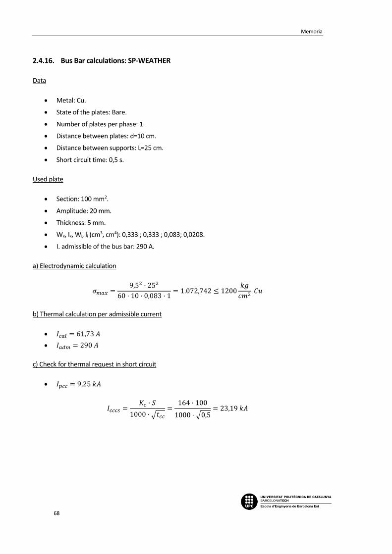
Memoria
68
2.4.16. Bus Bar calculations: SP-WEATHER
Data
Metal: Cu.
State of the plates: Bare.
Number of plates per phase: 1.
Distance between plates: d=10 cm.
Distance between supports: L=25 cm.
Short circuit time: 0,5 s.
Used plate
Section: 100 mm2.
Amplitude: 20 mm.
Thickness: 5 mm.
Wx, Ix, Wi, li (cm3, cm4): 0,333 ; 0,333 ; 0,083; 0,0208.
I. admissible of the bus bar: 290 A.
a) Electrodynamic calculation
𝜎𝑚𝑎𝑥 =9,5
2 · 252
60 · 10 · 0,083 · 1= 1.072,742 ≤ 1200
𝑘𝑔
𝑐𝑚2 𝐶𝑢
b) Thermal calculation per admissible current
𝐼𝑐𝑎𝑙 = 61,73 𝐴
𝐼𝑎𝑑𝑚 = 290 𝐴
c) Check for thermal request in short circuit
𝐼𝑝𝑐𝑐 = 9,25 𝑘𝐴
𝐼𝑐𝑐𝑐𝑠 =𝐾𝑐 · 𝑆
1000 · √𝑡𝑐𝑐
=164 · 100
1000 · √0,5= 23,19 𝑘𝐴

Electrification project in a box factory
69
2.5. Sub-panel SP-COMP
2.5.1. Power demand
-Total installed power:
COM01 30.000 W
COM03 30.000 W
DRY01 300 W
LT01 250 W
EMERGENCY 50 W
COM02 15.000 W
SUCTION 15.500 W
PLUG01 2.500 W
SERVICE BOXES 3.000 W
SW V P 5.500 W
2.5.2. Calculation line: COM01
Service Voltage: 400 V.
Canalization: B1-Unip. Superficial tube or Built-in.
Longitude: 25 m; Cos 𝜑: 0,8; Xu: 0 mΩ/m; R: 1;
Power to install: 30.000 W.
Calculation power (according to ITC BT-47):
𝑃 = 30.000 · 1,25 = 37.500 𝑊
𝐼 =37.500
0,8 · 400 · √3 · 1= 67,66 𝐴
We try unipolar conductors 4x35+TTx16mm2 Cu
Level of insulation: 0,6/1 kV, XPLE. Designed: UNE: RZ1-K (AS).
According to ITC BT-19 the maximum current admissible of the selected conductors at 40ºC
is 119A.
Outer tube diameter: 50 mm.

Memoria
70
Tension fall:
Cable temperature: 56,16ºC
𝑒(𝑝𝑎𝑟𝑡𝑖𝑎𝑙) =25·37.500
48,66·400·35= 1,38 𝑉 = 0,34%
𝑒(𝑡𝑜𝑡𝑎𝑙)=1,41% maximum admissible 6,5%
Thermic protection
Four pole automatic switch In: 100 A. Thermic regulation Ireg= 100 A.
Differential protection:
Relay and differential transformer sensitivity: 300mA. AC class [s].
Switching element
Four pole contactor In=100 A.
2.5.3. Calculation line: COM03
Service Voltage: 400 V.
Canalization: B2-Mult. Superficial tube or Built-in.
Longitude: 25 m; Cos 𝜑: 0,8; Xu: 0 mΩ/m; R: 1;
Power to install: 30.000 W.
Calculation power (according to ITC BT-47):
𝑃 = 30.000 · 1,25 = 37.500 𝑊
𝐼 =37.500
0,8 · 400 · √3 · 1= 67,66 𝐴
We try four pole conductors 4x35+TTx16mm2 Cu
Level of insulation: 0,6/1 kV, XPLE. Designed: UNE: RZ1-K (AS).
According to ITC BT-19 the maximum current admissible of the selected conductors at 40ºC
is 110A.
Outer tube diameter: 50 mm.
Tension fall:
Cable temperature: 58,92ºC
𝑒(𝑝𝑎𝑟𝑡𝑖𝑎𝑙) =25·37.500
48,2·400·35= 1,39 𝑉 = 0,35%
𝑒(𝑡𝑜𝑡𝑎𝑙)=1,41% maximum admissible 6,5%
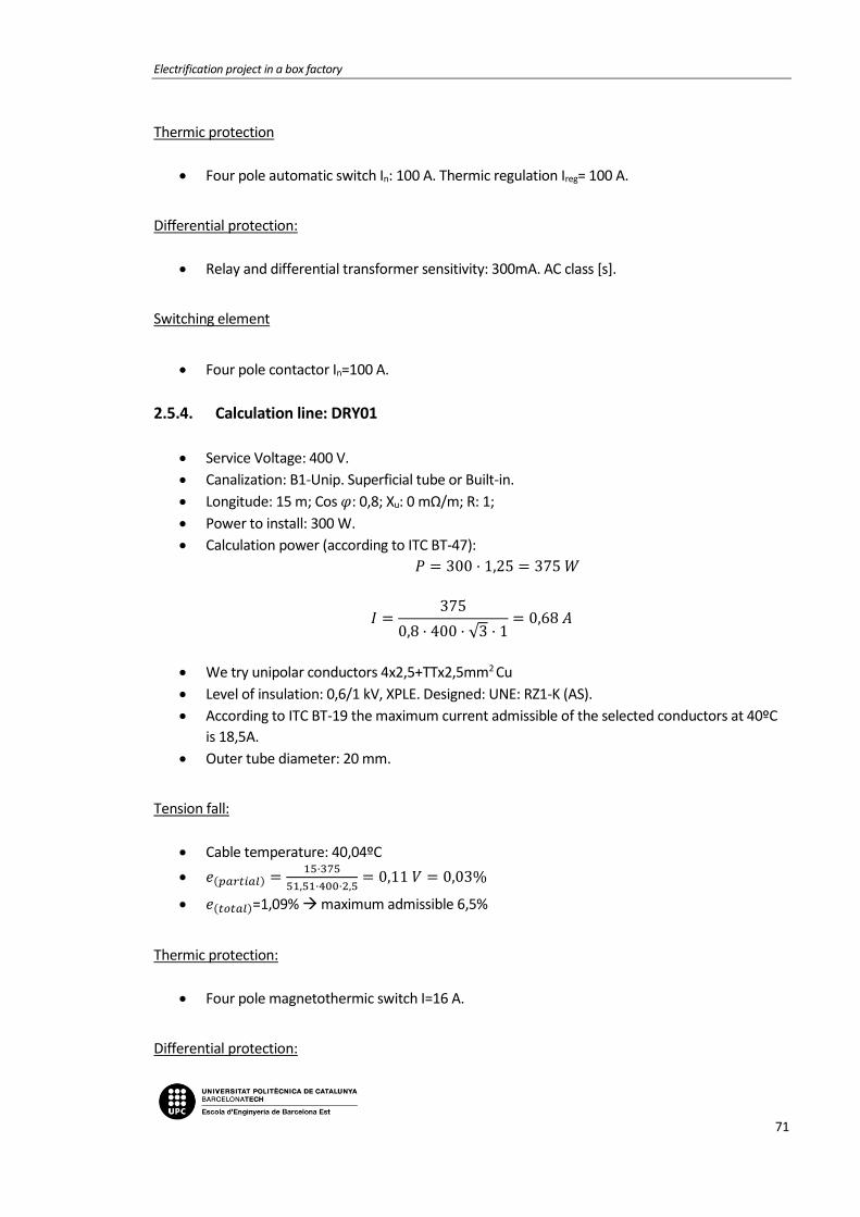
Electrification project in a box factory
71
Thermic protection
Four pole automatic switch In: 100 A. Thermic regulation Ireg= 100 A.
Differential protection:
Relay and differential transformer sensitivity: 300mA. AC class [s].
Switching element
Four pole contactor In=100 A.
2.5.4. Calculation line: DRY01
Service Voltage: 400 V.
Canalization: B1-Unip. Superficial tube or Built-in.
Longitude: 15 m; Cos 𝜑: 0,8; Xu: 0 mΩ/m; R: 1;
Power to install: 300 W.
Calculation power (according to ITC BT-47):
𝑃 = 300 · 1,25 = 375 𝑊
𝐼 =375
0,8 · 400 · √3 · 1= 0,68 𝐴
We try unipolar conductors 4x2,5+TTx2,5mm2 Cu
Level of insulation: 0,6/1 kV, XPLE. Designed: UNE: RZ1-K (AS).
According to ITC BT-19 the maximum current admissible of the selected conductors at 40ºC
is 18,5A.
Outer tube diameter: 20 mm.
Tension fall:
Cable temperature: 40,04ºC
𝑒(𝑝𝑎𝑟𝑡𝑖𝑎𝑙) =15·375
51,51·400·2,5= 0,11 𝑉 = 0,03%
𝑒(𝑡𝑜𝑡𝑎𝑙)=1,09% maximum admissible 6,5%
Thermic protection:
Four pole magnetothermic switch I=16 A.
Differential protection:

Memoria
72
Four pole differential switch I=25 A. Sens. I=300 mA. AC class.
Switching element
Four pole contactor In=16 A.
2.5.5. Calculation line: COMP-2
Service Voltage: 230 V.
Canalization: C-Unip. or Mult. on wall.
Longitude: 0,3 m; Cos 𝜑: 0,8; Xu: 0 mΩ/m;
Power to install: 300 W.
Simultaneity factor: 0,5.
Calculation power (according to ITC BT-44):
𝑃 = 270 𝑊
𝐼 =270
230 · 0,8= 1,47 𝐴
We try unipolar conductors 2x2,5+TTx2,5mm2 Cu
Level of insulation: 0,6/1 V, XPLE. Designed: UNE: RZ1-K (AS).
According to ITC BT-19 the maximum current admissible of the selected conductors at 40ºC
is 23 A.
Tension fall:
Cable temperature: 40,12ºC
𝑒(𝑝𝑎𝑟𝑡𝑖𝑎𝑙) =2·0,3·270
51,49·230·2,5= 0,01𝑉 = 0%
𝑒(𝑡𝑜𝑡𝑎𝑙)=1,07% maximum admissible 4,5%
Differential protection:
Two pole differential switch I=25 A. Sens. I=30 mA. AC class.
2.5.6. Calculation line: LT01
Service Voltage: 230 V.
Canalization: B1-Unip. tube superf. or built-in.
Longitude: 15 m; Cos 𝜑: 1; Xu: 0 mΩ/m;
Power to install: 250 W.
Calculation power (according to ITC BT-44):
𝑃 = 250 · 1,8 = 450 𝑊

Electrification project in a box factory
73
𝐼 =450
230 · 1= 1,96 𝐴
We try unipolar conductors 2x1,5+TTx1,5mm2 Cu
Level of insulation: 0,6/1 V, XPLE. Designed: UNE: RZ1-K (AS).
According to ITC BT-19 the maximum current admissible of the selected conductors at 40ºC
is 15 A.
Outer tube diameter: 16 mm.
Tension fall:
Cable temperature: 40,51ºC
𝑒(𝑝𝑎𝑟𝑡𝑖𝑎𝑙) =2·15·450
51,42·230·1,5= 0,76𝑉 = 0,33%
𝑒(𝑡𝑜𝑡𝑎𝑙)=1,4% maximum admissible 4,5%
Thermic protection:
Two pole magnetothermic switch I=10 A.
2.5.7. Calculation line: EMERGENCY
Service Voltage: 230 V.
Canalization: B1-Unip. tube superf. or Built-in.
Longitude: 15 m; Cos 𝜑: 1; Xu: 0 mΩ/m;
Power to install: 50 W.
Calculation power (according to ITC BT-44):
𝑃 = 50 · 1,8 = 90 𝑊
𝐼 =90
230= 0,39 𝐴
We try unipolar conductors 2x1,5+TTx1,5mm2 Cu
Level of insulation: 0,6/1 V, XPLE. Designed: UNE: RZ1-K (AS).
According to ITC BT-19 the maximum current admissible of the selected conductors at 40ºC
is 15 A.
Outer tube diameter: 16 mm.
Tension fall:
Cable temperature: 40,02ºC

Memoria
74
𝑒(𝑝𝑎𝑟𝑡𝑖𝑎𝑙) =2·15·90
51,51·230·1,5= 0,15𝑉 = 0,07%
𝑒(𝑡𝑜𝑡𝑎𝑙)=1,14% maximum admissible 4,5%
Thermic protection:
Two pole magnetothermic switch I=10 A.
2.5.8. Calculation line: COM02
Service Voltage: 400 V.
Canalization: B1-Unip.. Superficial tube or Built-in.
Longitude: 20 m; Cos 𝜑: 0,8; Xu: 0 mΩ/m; R: 1;
Power to install: 15.000 W.
Calculation power (according to ITC BT-47):
𝑃 = 15.000 · 1,25 = 18.750 𝑊
𝐼 =18.750
0,8 · 400 · √3 · 1= 33,83 𝐴
We try unipolar conductors 4x16+TTx16mm2 Cu
Level of insulation: 0,6/1 kV, XPLE. Designed: UNE: RZ1-K (AS).
According to ITC BT-19 the maximum current admissible of the selected conductors at 40ºC
is 73A.
Outer tube diameter: 40 mm.
Tension fall:
Cable temperature: 50,74ºC
𝑒(𝑝𝑎𝑟𝑡𝑖𝑎𝑙) =20·18.750
49,58·400·16= 1,18 𝑉 = 0,3%
𝑒(𝑡𝑜𝑡𝑎𝑙)=1,36% maximum admissible 6,5%
Thermic protection:
Four pole magnetothermic switch I=63 A.
Differential protection:
Four pole differential switch I=63 A. Sens. I=300 mA. AC class.
Switching element

Electrification project in a box factory
75
Four pole contactor In=63 A.
2.5.9. Calculation line: SUCTION
Service Voltage: 400 V.
Canalization: B1-Unip. Superficial tube or Built-in.
Longitude: 50 m; Cos 𝜑: 0,8; Xu: 0 mΩ/m; R: 1;
Power to install: 15.500 W.
Calculation power (according to ITC BT-47):
𝑃 = 500 · 1,25 + 15.000 = 15.625 𝑊
𝐼 =15.625
0,8 · 400 · √3 · 1= 28,19 𝐴
We try unipolar conductors 4x10+TTx10mm2 Cu
Level of insulation: 0,6/1 kV, XPLE. Designed: UNE: RZ1-K (AS).
According to ITC BT-19 the maximum current admissible of the selected conductors at 40ºC
is 54A.
Outer tube diameter: 32 mm.
Tension fall:
Cable temperature: 53,63ºC
𝑒(𝑝𝑎𝑟𝑡𝑖𝑎𝑙) =50·15.625
49,09·400·10= 3,98 𝑉 = 0,99%
𝑒(𝑡𝑜𝑡𝑎𝑙)=2,06% maximum admissible 6,5%
Thermic protection:
Four pole magnetothermic switch I=32 A.
Differential protection:
Four pole differential switch I=40 A. Sens. I=300 mA. AC class.
2.5.10. Calculation line: PLUG01
Service Voltage: 400 V.
Canalization: B1-Unip. Superficial tube or Built-in.
Longitude: 25 m; Cos 𝜑: 0,8; Xu: 0 mΩ/m; R: 1;
Power to install: 2.500 W.
Calculation power: 2.500 W

Memoria
76
𝐼 =2.500
0,8 · 400 · √3 · 1= 4,51 𝐴
We try unipolar conductors 4x2,5+TTx2,5mm2 Cu
Level of insulation: 0,6/1 V, XPLE. Designed: UNE: RZ1-K (AS).
According to ITC BT-19 the maximum current admissible of the selected conductors at 40ºC
is 18,5A.
Outer tube diameter: 20 mm.
Tension fall:
Cable temperature: 41,78ºC
𝑒(𝑝𝑎𝑟𝑡𝑖𝑎𝑙) =25·2.500
51,18·400·2,5= 1,22 𝑉 = 0,31%
𝑒(𝑡𝑜𝑡𝑎𝑙)=1,37% maximum admissible 6,5%
Thermic protection:
Four pole magnetothermic switch I=16 A.
Differential protection:
Four pole differential switch I=25 A. Sens. I=30 mA. AC class.
2.5.11. Calculation line: SERVICE BOXES
Service Voltage: 400 V.
Canalization: B1-Unip. Superficial tube or Built-in.
Longitude: 15 m; Cos 𝜑: 0,8; Xu: 0 mΩ/m;
Power to install: 3.000 W.
Calculation power: 3.000 W
𝐼 =3.000
0,8 · 400 · √3= 5,41 𝐴
We try unipolar conductors 4x10+TTx10mm2 Cu
Level of insulation: 0,6/1 V, XPLE. Designed: UNE: RZ1-K (AS).
According to ITC BT-19 the maximum current admissible of the selected conductors at 40ºC
is 44A.
Outer tube diameter: 32 mm.

Electrification project in a box factory
77
Tension fall:
Cable temperature: 40,45ºC
𝑒(𝑝𝑎𝑟𝑡𝑖𝑎𝑙) =15·3.000
51,43·400·10= 0,22 𝑉 = 0,05%
𝑒(𝑡𝑜𝑡𝑎𝑙)=1,12% maximum admissible 6,5%
Thermic protection:
Four pole magnetothermic switch I=40 A.
Differential protection:
Four pole differential switch I=40 A. Sens. I=30 mA. AC class.
2.5.12. Calculation line: SW V P
Service Voltage: 400 V.
Canalization: B1-Unip. Superficial tube or Built-in.
Longitude: 20 m; Cos 𝜑: 0,8; Xu: 0 mΩ/m; R: 1;
Power to install: 5.500 W.
Calculation power (according to ITC BT-47):
𝑃 = 500 · 1,25 + 5.000 = 5.625 𝑊
𝐼 =5.625
0,8 · 400 · √3 · 1= 10,15 𝐴
We try unipolar conductors 4x2,5+TTx2,5mm2 Cu
Level of insulation: 0,6/1 V, XPLE. Designed: UNE: RZ1-K (AS).
According to ITC BT-19 the maximum current admissible of the selected conductors at 40ºC
is 18,5A.
Outer tube diameter: 20 mm.
Tension fall:
Cable temperature: 49,03ºC
𝑒(𝑝𝑎𝑟𝑡𝑖𝑎𝑙) =20·5.625
59,88·400·2,5= 2,23 𝑉 = 0,56%
𝑒(𝑡𝑜𝑡𝑎𝑙)=1,63% maximum admissible 6,5%
Thermic protection:
Four pole magnetothermic switch I=16 A.

Memoria
78
Differential protection:
Four pole differential switch I=25 A. Sens. I=300 mA. AC class.
2.5.13. Bus Bar calculations: SP-COMP
Data
Metal: Cu.
State of the plates: Bare.
Number of plates per phase: 1.
Distance between plates: d=10 cm.
Distance between supports: L=25 cm.
Short circuit time: 0,5 s.
Used plate
Section: 100 mm2.
Amplitude: 20 mm.
Thickness: 5 mm.
Wx, Ix, Wi, li (cm3, cm4): 0,333 ; 0,333 ; 0,083; 0,0208.
I. admissible of the bus bar: 290 A.
a) Electrodynamic calculation
𝜎𝑚𝑎𝑥 =9,5
2 · 252
60 · 10 · 0,083 · 1= 1.072,742 ≤ 1200
𝑘𝑔
𝑐𝑚2 𝐶𝑢
b) Thermal calculation per admissible current
𝐼𝑐𝑎𝑙 = 124,32 𝐴
𝐼𝑎𝑑𝑚 = 290 𝐴
c) Check for thermal request in short circuit
𝐼𝑝𝑐𝑐 = 9,25 𝑘𝐴
𝐼𝑐𝑐𝑐𝑠 =𝐾𝑐 · 𝑆
1000 · √𝑡𝑐𝑐
=164 · 100
1000 · √0,5= 23,19 𝑘𝐴

Electrification project in a box factory
79
2.6. Sub-panel SP-WAREHOUSE
2.6.1. Power demand
-Total installed power:
CBA01 1.000 W
CBA02 1.000 W
CBA03 7.000 W
CBA04 20.000 W
DOOR01 1.104 W
DOOR02 1.472 W
DOOR03 1.235 W
DOOR04 1.500 W
LP01 2.944 W
LP02 2.944 W
AER01 1.360 W
AER02 700 W
AER03 700W
SB 4.500 W
SP-OFILOG 9.660 W
BRIDGE 5.875 W
BACKUP 0 W
2.6.2. Calculation line: WAREHOUSE 0
Service Voltage: 230 V.

Memoria
80
Canalization: C-Unip. or Mult. on wall.
Longitude: 0,3 m; Cos 𝜑: 0,8; Xu: 0 mΩ/m;
Power to install: 2.000 W.
Simultaneity factor: 0,5.
Calculation power: 1.000 W
𝐼 =1.000
0,8 · 230= 5,43 𝐴
We try unipolar conductors 2x6mm2 Cu
Level of insulation: 0,6/1 V, XPLE. Designed: UNE: RZ1-K (AS).
According to ITC BT-19 the maximum current admissible of the selected conductors at 40ºC
is 40A.
Tension fall:
Cable temperature: 40,55ºC
𝑒(𝑝𝑎𝑟𝑡𝑖𝑎𝑙) =2·2,3·1.000
51,41·230·6= 0,01 𝑉 = 0%
𝑒(𝑡𝑜𝑡𝑎𝑙)=1,54% maximum admissible 4,5%
Differential protection:
Two pole differential switch I=25 A. Sens. I=30 mA. AC class.
2.6.3. Calculation line: CBA01
Service Voltage: 230 V.
Canalization: B1-Unip. Superficial tube or Built-in.
Longitude: 18 m; Cos 𝜑: 0,8; Xu: 0 mΩ/m;
Power to install: 1.000 W.
Calculation power: 1.000 W
𝐼 =1.000
0,8 · 230= 5,43 𝐴
We try unipolar conductors 2x2,5+TTX2,5mm2 Cu
Level of insulation: 0,6/1 V, XPLE. Designed: UNE: RZ1-K (AS).
According to ITC BT-19 the maximum current admissible of the selected conductors at 40ºC
is 21A.
Outer tube diameter: 20 mm.
Tension fall:

Electrification project in a box factory
81
Cable temperature: 42,01ºC
𝑒(𝑝𝑎𝑟𝑡𝑖𝑎𝑙) =2·18·1.000
51,14·230·2,5= 1,22 𝑉 = 0,53%
𝑒(𝑡𝑜𝑡𝑎𝑙)=2,07% maximum admissible 6,5%
Thermic protection:
Two pole magnetothermic switch I=16 A.
2.6.4. Calculation line: CBA02
Service Voltage: 230 V.
Canalization: B1-Unip. Superficial tube or Built-in.
Longitude: 19 m; Cos 𝜑: 0,8; Xu: 0 mΩ/m;
Power to install: 1.000 W.
Calculation power: 1.000 W
𝐼 =1.000
0,8 · 230= 5,43 𝐴
We try unipolar conductors 2x2,5+TTX2,5mm2 Cu
Level of insulation: 0,6/1 V, XPLE. Designed: UNE: RZ1-K (AS).
According to ITC BT-19 the maximum current admissible of the selected conductors at 40ºC
is 21A.
Outer tube diameter: 20 mm.
Tension fall:
Cable temperature: 42,01ºC
𝑒(𝑝𝑎𝑟𝑡𝑖𝑎𝑙) =2·19·1.000
51,14·230·2,5= 1,29 𝑉 = 0,56%
𝑒(𝑡𝑜𝑡𝑎𝑙)=2,1% maximum admissible 6,5%
Thermic protection:
Two pole magnetothermic switch I=16 A.
2.6.5. Calculation line: WAREHOUSE 1
Service Voltage: 400 V.
Canalization: C-Unip. or Mult. on wall.
Longitude: 0,3 m; Cos 𝜑: 0,8; Xu: 0 mΩ/m;
Power to install: 27.000 W.
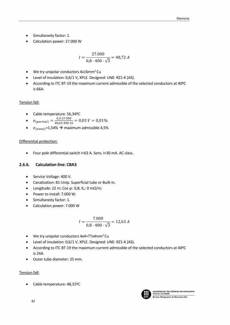
Memoria
82
Simultaneity factor: 1.
Calculation power: 27.000 W
𝐼 =27.000
0,8 · 400 · √3= 48,72 𝐴
We try unipolar conductors 4x16mm2 Cu
Level of insulation: 0,6/1 V, XPLE. Designed: UNE: RZ1-K (AS).
According to ITC BT-19 the maximum current admissible of the selected conductors at 40ºC
is 66A.
Tension fall:
Cable temperature: 56,34ºC
𝑒(𝑝𝑎𝑟𝑡𝑖𝑎𝑙) =0,3·27.000
48,63·400·16= 0,03 𝑉 = 0,01%
𝑒(𝑡𝑜𝑡𝑎𝑙)=1,54% maximum admissible 4,5%
Differential protection:
Four pole differential switch I=63 A. Sens. I=30 mA. AC class.
2.6.6. Calculation line: CBA3
Service Voltage: 400 V.
Canalization: B1-Unip. Superficial tube or Built-in.
Longitude: 22 m; Cos 𝜑: 0,8; Xu: 0 mΩ/m;
Power to install: 7.000 W.
Simultaneity factor: 1.
Calculation power: 7.000 W
𝐼 =7.000
0,8 · 400 · √3= 12,63 𝐴
We try unipolar conductors 4x4+TTx4mm2 Cu
Level of insulation: 0,6/1 V, XPLE. Designed: UNE: RZ1-K (AS).
According to ITC BT-19 the maximum current admissible of the selected conductors at 40ºC
is 24A.
Outer tube diameter: 25 mm.
Tension fall:
Cable temperature: 48,31ºC
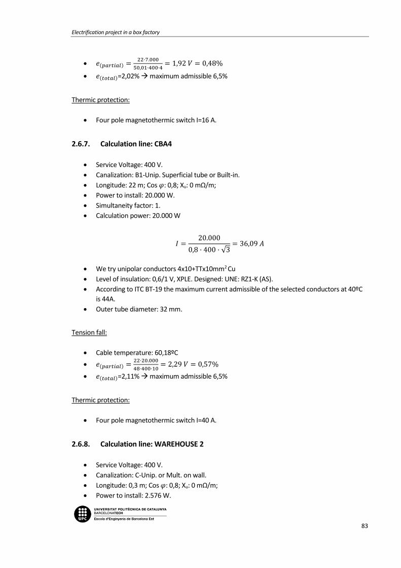
Electrification project in a box factory
83
𝑒(𝑝𝑎𝑟𝑡𝑖𝑎𝑙) =22·7.000
50,01·400·4= 1,92 𝑉 = 0,48%
𝑒(𝑡𝑜𝑡𝑎𝑙)=2,02% maximum admissible 6,5%
Thermic protection:
Four pole magnetothermic switch I=16 A.
2.6.7. Calculation line: CBA4
Service Voltage: 400 V.
Canalization: B1-Unip. Superficial tube or Built-in.
Longitude: 22 m; Cos 𝜑: 0,8; Xu: 0 mΩ/m;
Power to install: 20.000 W.
Simultaneity factor: 1.
Calculation power: 20.000 W
𝐼 =20.000
0,8 · 400 · √3= 36,09 𝐴
We try unipolar conductors 4x10+TTx10mm2 Cu
Level of insulation: 0,6/1 V, XPLE. Designed: UNE: RZ1-K (AS).
According to ITC BT-19 the maximum current admissible of the selected conductors at 40ºC
is 44A.
Outer tube diameter: 32 mm.
Tension fall:
Cable temperature: 60,18ºC
𝑒(𝑝𝑎𝑟𝑡𝑖𝑎𝑙) =22·20.000
48·400·10= 2,29 𝑉 = 0,57%
𝑒(𝑡𝑜𝑡𝑎𝑙)=2,11% maximum admissible 6,5%
Thermic protection:
Four pole magnetothermic switch I=40 A.
2.6.8. Calculation line: WAREHOUSE 2
Service Voltage: 400 V.
Canalization: C-Unip. or Mult. on wall.
Longitude: 0,3 m; Cos 𝜑: 0,8; Xu: 0 mΩ/m;
Power to install: 2.576 W.

Memoria
84
Simultaneity factor: 0,5
Calculation power (according to ITC BT-47):
𝑃 = 368 · 1,25 + 920 = 1.380 𝑊
𝐼 =1.380
0,8 · 400 · √3= 2,49 𝐴
We try unipolar conductors 4x6mm2 Cu
Level of insulation: 0,6/1 V, XPLE. Designed: UNE: RZ1-K (AS).
According to ITC BT-19 the maximum current admissible of the selected conductors at 40ºC
is 36A.
Tension fall:
Cable temperature: 40,14ºC
𝑒(𝑝𝑎𝑟𝑡𝑖𝑎𝑙) =0,3·1.380
51,49·400·6= 0 𝑉 = 0%
𝑒(𝑡𝑜𝑡𝑎𝑙)=1,54% maximum admissible 4,5%
Differential protection:
Four pole differential switch I=40 A. Sens. I=30 mA. AC class.
2.6.9. Calculation line: DOOR01
Service Voltage: 400 V.
Canalization: B1-Unip. Superficial tube or Built-in.
Longitude: 56 m; Cos 𝜑: 0,8; Xu: 0 mΩ/m; R: 1;
Power to install: 1.104 W.
Calculation power (according to ITC BT-47):
𝑃 = 368 · 1,25 + 736 = 1.196 𝑊
𝐼 =1.196
0,8 · 400 · √3 · 1= 2,16 𝐴
We try unipolar conductors 4x2,5+TTx2,5mm2 Cu
Level of insulation: 0,6/1 kV, XPLE. Designed: UNE: RZ1-K (AS).
According to ITC BT-19 the maximum current admissible of the selected conductors at 40ºC
is 18,5A.
Outer tube diameter: 20 mm.
Tension fall:

Electrification project in a box factory
85
Cable temperature: 40,41ºC
𝑒(𝑝𝑎𝑟𝑡𝑖𝑎𝑙) =56·1.196
51,44·400·2,5= 1,3 𝑉 = 0,33%
𝑒(𝑡𝑜𝑡𝑎𝑙)=1,86% maximum admissible 6,5%
Thermic protection:
Four pole magnetothermic switch I=16 A.
2.6.10. Calculation line: DOOR02
Service Voltage: 400 V.
Canalization: B1-Unip. Superficial tube or Built-in.
Longitude: 54 m; Cos 𝜑: 0,8; Xu: 0 mΩ/m; R: 1;
Power to install: 1.472 W.
Calculation power (according to ITC BT-47):
𝑃 = 368 · 1,25 + 1.104 = 1.564 𝑊
𝐼 =1.564
0,8 · 400 · √3 · 1= 2,82 𝐴
We try unipolar conductors 4x2,5+TTx2,5mm2 Cu
Level of insulation: 0,6/1 kV, XPLE. Designed: UNE: RZ1-K (AS).
According to ITC BT-19 the maximum current admissible of the selected conductors at 40ºC
is 18,5A.
Outer tube diameter: 20 mm.
Tension fall:
Cable temperature: 40,7ºC
𝑒(𝑝𝑎𝑟𝑡𝑖𝑎𝑙) =54·1.564
51,39·400·2,5= 1,64 𝑉 = 0,41%
𝑒(𝑡𝑜𝑡𝑎𝑙)=1,95% maximum admissible 6,5%
Thermic protection:
Four pole magnetothermic switch I=16 A.
2.6.11. Calculation line: WAREHOUSE 3
Service Voltage: 400 V.
Canalization: C-Unip. or Mult. on wall.
Longitude: 0,3 m; Cos 𝜑: 0,8; Xu: 0 mΩ/m;
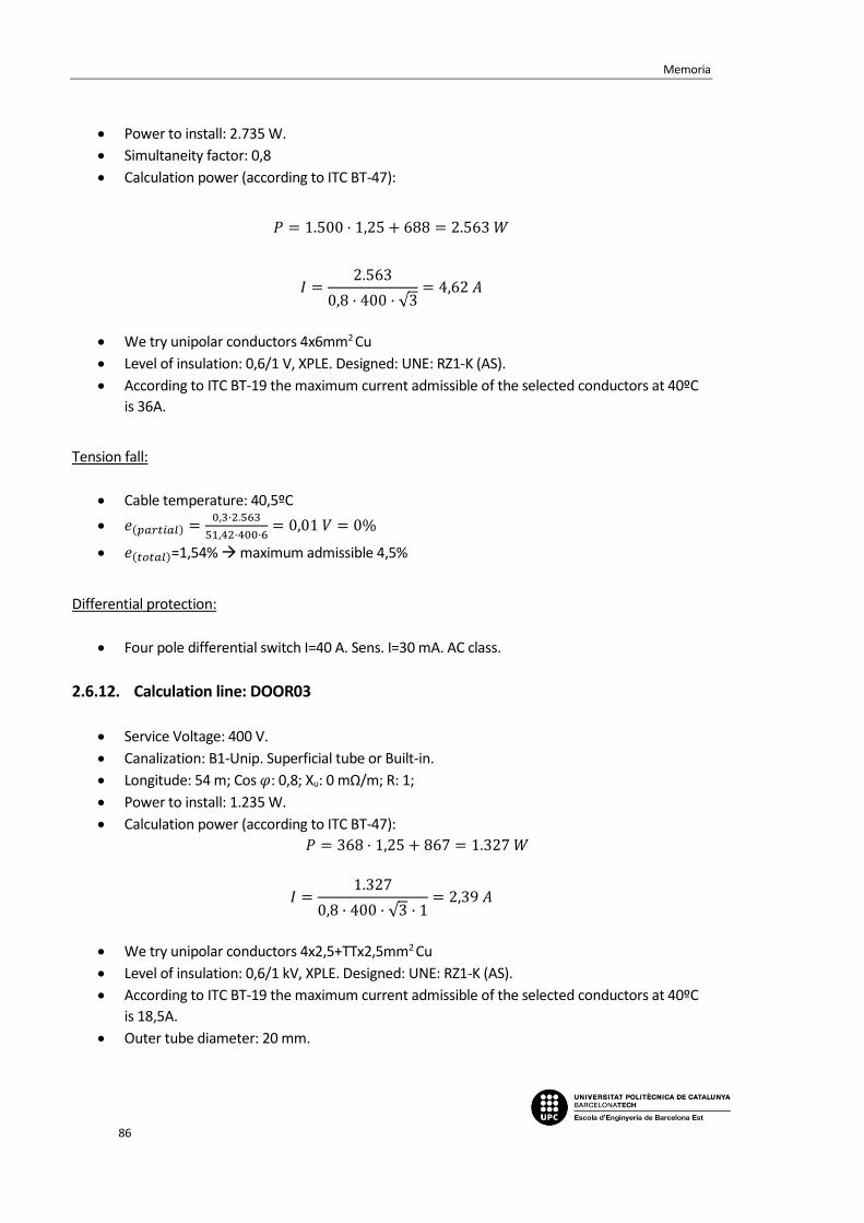
Memoria
86
Power to install: 2.735 W.
Simultaneity factor: 0,8
Calculation power (according to ITC BT-47):
𝑃 = 1.500 · 1,25 + 688 = 2.563 𝑊
𝐼 =2.563
0,8 · 400 · √3= 4,62 𝐴
We try unipolar conductors 4x6mm2 Cu
Level of insulation: 0,6/1 V, XPLE. Designed: UNE: RZ1-K (AS).
According to ITC BT-19 the maximum current admissible of the selected conductors at 40ºC
is 36A.
Tension fall:
Cable temperature: 40,5ºC
𝑒(𝑝𝑎𝑟𝑡𝑖𝑎𝑙) =0,3·2.563
51,42·400·6= 0,01 𝑉 = 0%
𝑒(𝑡𝑜𝑡𝑎𝑙)=1,54% maximum admissible 4,5%
Differential protection:
Four pole differential switch I=40 A. Sens. I=30 mA. AC class.
2.6.12. Calculation line: DOOR03
Service Voltage: 400 V.
Canalization: B1-Unip. Superficial tube or Built-in.
Longitude: 54 m; Cos 𝜑: 0,8; Xu: 0 mΩ/m; R: 1;
Power to install: 1.235 W.
Calculation power (according to ITC BT-47):
𝑃 = 368 · 1,25 + 867 = 1.327 𝑊
𝐼 =1.327
0,8 · 400 · √3 · 1= 2,39 𝐴
We try unipolar conductors 4x2,5+TTx2,5mm2 Cu
Level of insulation: 0,6/1 kV, XPLE. Designed: UNE: RZ1-K (AS).
According to ITC BT-19 the maximum current admissible of the selected conductors at 40ºC
is 18,5A.
Outer tube diameter: 20 mm.

Electrification project in a box factory
87
Tension fall:
Cable temperature: 40,5ºC
𝑒(𝑝𝑎𝑟𝑡𝑖𝑎𝑙) =54·1.327
51,42·400·2,5= 1,39 𝑉 = 0,35%
𝑒(𝑡𝑜𝑡𝑎𝑙)=1,88% maximum admissible 6,5%
Thermic protection:
Four pole magnetothermic switch I=16 A.
2.6.13. Calculation line: DOOR04
Service Voltage: 400 V.
Canalization: B1-Unip. Superficial tube or Built-in.
Longitude: 55 m; Cos 𝜑: 0,8; Xu: 0 mΩ/m; R: 1;
Power to install: 1.500 W.
Calculation power (according to ITC BT-47):
𝑃 = 1.500 · 1,25 = 1.875 𝑊
𝐼 =1.875
0,8 · 400 · √3 · 1= 3,38 𝐴
We try unipolar conductors 4x2,5+TTx2,5mm2 Cu
Level of insulation: 0,6/1 kV, XPLE. Designed: UNE: RZ1-K (AS).
According to ITC BT-19 the maximum current admissible of the selected conductors at 40ºC
is 18,5A.
Outer tube diameter: 20 mm.
Tension fall:
Cable temperature: 41ºC
𝑒(𝑝𝑎𝑟𝑡𝑖𝑎𝑙) =55·1.875
51,33·400·2,5= 2,01 𝑉 = 0,5%
𝑒(𝑡𝑜𝑡𝑎𝑙)=2,04% maximum admissible 6,5%
Thermic protection:
Four pole magnetothermic switch I=16 A.
2.6.14. Calculation line: WAREHOUSE 4
Service Voltage: 400 V.
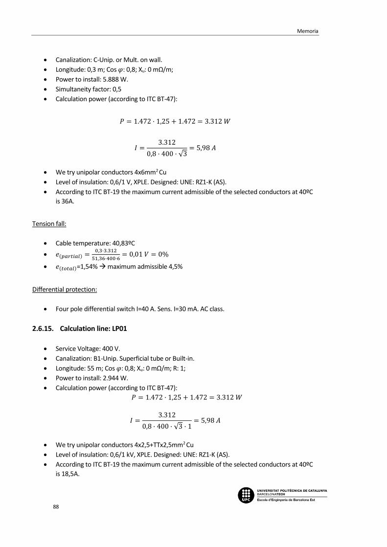
Memoria
88
Canalization: C-Unip. or Mult. on wall.
Longitude: 0,3 m; Cos 𝜑: 0,8; Xu: 0 mΩ/m;
Power to install: 5.888 W.
Simultaneity factor: 0,5
Calculation power (according to ITC BT-47):
𝑃 = 1.472 · 1,25 + 1.472 = 3.312 𝑊
𝐼 =3.312
0,8 · 400 · √3= 5,98 𝐴
We try unipolar conductors 4x6mm2 Cu
Level of insulation: 0,6/1 V, XPLE. Designed: UNE: RZ1-K (AS).
According to ITC BT-19 the maximum current admissible of the selected conductors at 40ºC
is 36A.
Tension fall:
Cable temperature: 40,83ºC
𝑒(𝑝𝑎𝑟𝑡𝑖𝑎𝑙) =0,3·3.312
51,36·400·6= 0,01 𝑉 = 0%
𝑒(𝑡𝑜𝑡𝑎𝑙)=1,54% maximum admissible 4,5%
Differential protection:
Four pole differential switch I=40 A. Sens. I=30 mA. AC class.
2.6.15. Calculation line: LP01
Service Voltage: 400 V.
Canalization: B1-Unip. Superficial tube or Built-in.
Longitude: 55 m; Cos 𝜑: 0,8; Xu: 0 mΩ/m; R: 1;
Power to install: 2.944 W.
Calculation power (according to ITC BT-47):
𝑃 = 1.472 · 1,25 + 1.472 = 3.312 𝑊
𝐼 =3.312
0,8 · 400 · √3 · 1= 5,98 𝐴
We try unipolar conductors 4x2,5+TTx2,5mm2 Cu
Level of insulation: 0,6/1 kV, XPLE. Designed: UNE: RZ1-K (AS).
According to ITC BT-19 the maximum current admissible of the selected conductors at 40ºC
is 18,5A.

Electrification project in a box factory
89
Outer tube diameter: 20 mm.
Tension fall:
Cable temperature: 43,13ºC
𝑒(𝑝𝑎𝑟𝑡𝑖𝑎𝑙) =55·3.312
50,94·400·2,5= 3,58 𝑉 = 0,89%
𝑒(𝑡𝑜𝑡𝑎𝑙)=2,43% maximum admissible 6,5%
Thermic protection:
Four pole magnetothermic switch I=16 A.
2.6.16. Calculation line: LP02
Service Voltage: 400 V.
Canalization: B1-Unip. Superficial tube or Built-in.
Longitude: 55 m; Cos 𝜑: 0,8; Xu: 0 mΩ/m; R: 1;
Power to install: 2.944 W.
Calculation power (according to ITC BT-47):
𝑃 = 1.472 · 1,25 + 1.472 = 3.312 𝑊
𝐼 =3.312
0,8 · 400 · √3 · 1= 5,98 𝐴
We try unipolar conductors 4x2,5+TTx2,5mm2 Cu
Level of insulation: 0,6/1 kV, XPLE. Designed: UNE: RZ1-K (AS).
According to ITC BT-19 the maximum current admissible of the selected conductors at 40ºC
is 18,5A.
Outer tube diameter: 20 mm.
Tension fall:
Cable temperature: 43,13ºC
𝑒(𝑝𝑎𝑟𝑡𝑖𝑎𝑙) =55·3.312
50,94·400·2,5= 3,58 𝑉 = 0,89%
𝑒(𝑡𝑜𝑡𝑎𝑙)=2,43% maximum admissible 6,5%
Thermic protection:
Four pole magnetothermic switch I=16 A.

Memoria
90
2.6.17. Calculation line: WAREHOUSE 5
Service Voltage: 400 V.
Canalization: C-Unip. or Mult. on wall.
Longitude: 0,3 m; Cos 𝜑: 0,8; Xu: 0 mΩ/m;
Power to install: 2.760 W.
Simultaneity factor: 0,5
Calculation power (according to ITC BT-47):
𝑃 = 100 · 1,25 + 1.280 = 1.405 𝑊
𝐼 =1.405
0,8 · 400 · √3= 2,54 𝐴
We try unipolar conductors 4x10mm2 Cu
Level of insulation: 0,6/1 V, XPLE. Designed: UNE: RZ1-K (AS).
According to ITC BT-19 the maximum current admissible of the selected conductors at 40ºC
is 50A.
Tension fall:
Cable temperature: 40,08ºC
𝑒(𝑝𝑎𝑟𝑡𝑖𝑎𝑙) =0,3·1.405
51,5·400·10= 0 𝑉 = 0%
𝑒(𝑡𝑜𝑡𝑎𝑙)=1,53% maximum admissible 4,5%
Differential protection:
Four pole differential switch I=63 A. Sens. I=30 mA. AC class.
2.6.18. Calculation line: AER01
Service Voltage: 400 V.
Canalization: B1-Unip. Superficial tube or Built-in.
Longitude: 35 m; Cos 𝜑: 0,8; Xu: 0 mΩ/m; R: 1;
Power to install: 1.360 W.
Calculation power (according to ITC BT-47):
𝑃 = 80 · 1,25 + 1.280 = 1.380 𝑊
𝐼 =1.380
0,8 · 400 · √3 · 1= 2,49 𝐴
We try unipolar conductors 4x2,5+TTx2,5mm2 Cu

Electrification project in a box factory
91
Level of insulation: 0,6/1 kV, XPLE. Designed: UNE: RZ1-K (AS).
According to ITC BT-19 the maximum current admissible of the selected conductors at 40ºC
is 18,5A.
Outer tube diameter: 20 mm.
Tension fall:
Cable temperature: 40,54ºC
𝑒(𝑝𝑎𝑟𝑡𝑖𝑎𝑙) =35·1.380
51,42·400·2,5= 0,94 𝑉 = 0,23%
𝑒(𝑡𝑜𝑡𝑎𝑙)=2,77% maximum admissible 6,5%
Thermic protection:
Four pole magnetothermic switch I=16 A.
2.6.19. Calculation line: AER02
Service Voltage: 400 V.
Canalization: B1-Unip. Superficial tube or Built-in.
Longitude: 36 m; Cos 𝜑: 0,8; Xu: 0 mΩ/m; R: 1;
Power to install: 700 W.
Calculation power (according to ITC BT-47):
𝑃 = 100 · 1,25 + 600 = 725 𝑊
𝐼 =725
0,8 · 400 · √3 · 1= 1,31 𝐴
We try unipolar conductors 4x2,5+TTx2,5mm2 Cu
Level of insulation: 0,6/1 kV, XPLE. Designed: UNE: RZ1-K (AS).
According to ITC BT-19 the maximum current admissible of the selected conductors at 40ºC
is 18,5A.
Outer tube diameter: 20 mm.
Tension fall:
Cable temperature: 40,15ºC
𝑒(𝑝𝑎𝑟𝑡𝑖𝑎𝑙) =36·725
51,49·400·2,5= 0,51 𝑉 = 0,13%
𝑒(𝑡𝑜𝑡𝑎𝑙)=1,66% maximum admissible 6,5%
Thermic protection:

Memoria
92
Four pole magnetothermic switch I=16 A.
2.6.20. Calculation line: AER03
Service Voltage: 400 V.
Canalization: B1-Unip. Superficial tube or Built-in.
Longitude: 37 m; Cos 𝜑: 0,8; Xu: 0 mΩ/m; R: 1;
Power to install: 700 W.
Calculation power (according to ITC BT-47):
𝑃 = 100 · 1,25 + 600 = 725 𝑊
𝐼 =725
0,8 · 400 · √3 · 1= 1,31 𝐴
We try unipolar conductors 4x2,5+TTx2,5mm2 Cu
Level of insulation: 0,6/1 kV, XPLE. Designed: UNE: RZ1-K (AS).
According to ITC BT-19 the maximum current admissible of the selected conductors at 40ºC
is 18,5A.
Outer tube diameter: 20 mm.
Tension fall:
Cable temperature: 40,15ºC
𝑒(𝑝𝑎𝑟𝑡𝑖𝑎𝑙) =37·725
51,49·400·2,5= 0,52 𝑉 = 0,13%
𝑒(𝑡𝑜𝑡𝑎𝑙)=1,66% maximum admissible 6,5%
Thermic protection:
Four pole magnetothermic switch I=16 A.
2.6.21. Calculation line: SB
Service Voltage: 400 V.
Canalization: B2-Mult. Superficial tube or Built-in.
Longitude: 32 m; Cos 𝜑: 0,8; Xu: 0 mΩ/m;
Power to install: 4.500 W.
Calculation power: 4.500 W
𝐼 =4.500
0,8 · 400 · √3= 8,12 𝐴

Electrification project in a box factory
93
We try four pole conductors 4x10+TTx10mm2 Cu
Level of insulation: 0,6/1 kV, XPLE. Designed: UNE: RZ1-K (AS).
According to ITC BT-19 the maximum current admissible of the selected conductors at 40ºC
is 52A.
Outer tube diameter: 32 mm.
Tension fall:
Cable temperature: 41,22ºC
𝑒(𝑝𝑎𝑟𝑡𝑖𝑎𝑙) =32·4.500
51,29·400·10= 0,7 𝑉 = 0,18%
𝑒(𝑡𝑜𝑡𝑎𝑙)=1,71% maximum admissible 6,5%
Thermic protection:
Four pole magnetothermic switch I=16 A.
Differential protection:
Four pole differential switch I=25 A. Sens. I=30 mA. AC class.
2.6.22. Calculation line: BRIDGE
Service Voltage: 400 V.
Canalization: B1-Unip. tube superf. or Built-in.
Longitude: 50 m; Cos 𝜑: 0,8; Xu: 0 mΩ/m; R=1;
Power to install: 5.875 W.
Calculation power (according to ITC BT-47):
𝑃 = 5.875𝑥1,25 = 7.343,75 𝑊
𝐼 =7.343,75
400 · √3 · 0,8 · 1= 13,25 𝐴
We try unipolar conductors 4x10+TTx10mm2 Cu
Level of insulation: 0,6/1 V, XPLE. Designed: UNE: RZ1-K (AS).
According to ITC BT-19 the maximum current admissible of the selected conductors at 40ºC
is 44 A.
Outer tube diameter: 32 mm.
Tension fall:

Memoria
94
Cable temperature: 42,72ºC
𝑒(𝑝𝑎𝑟𝑡𝑖𝑎𝑙) =50·7.343,75
51,01·400·10·1= 1,8𝑉 = 0,45%
𝑒(𝑡𝑜𝑡𝑎𝑙)=1,98% maximum admissible 6,5%
Thermic protection:
Four pole magnetothermic switch I=40 A.
Differential protection:
Four pole differential switch I=40 A. Sens. I=30 mA. AC class
2.6.23. Calculation line: BACKUP
Service Voltage: 400 V.
Canalization: B1-Unip. tube superf. or Built-in.
Longitude: 8 m; Cos 𝜑: 0,8; Xu: 0 mΩ/m;
Power to install: 1 W.
𝑃 = 1 𝑊
𝐼 =1
400 · √3 · 0,8 · 1= 0 𝐴
We try unipolar conductors 4x2,5+TTx2,5mm2 Cu
Level of insulation: 0,6/1 V, XPLE. Designed: UNE: RZ1-K (AS).
According to ITC BT-19 the maximum current admissible of the selected conductors at 40ºC
is 18,5 A.
Outer tube diameter: 20 mm.
Tension fall:
Cable temperature: 40ºC
𝑒(𝑝𝑎𝑟𝑡𝑖𝑎𝑙) =8·1
51,52·400·2,5= 0𝑉 = 0%
𝑒(𝑡𝑜𝑡𝑎𝑙)=1,53% maximum admissible 6,5%
Thermic protection:
Four pole magnetothermic switch I=16 A.
Differential protection:

Electrification project in a box factory
95
Four pole differential switch I=25 A. Sens. I=30 mA. AC class.
2.6.24. Bus Bar calculations: SP-WAREHOUSE
Data
Metal: Cu.
State of the plates: Bare.
Number of plates per phase: 1.
Distance between plates: d=10 cm.
Distance between supports: L=25 cm.
Short circuit time: 0,5 s.
Used plate
Section: 45 mm2.
Amplitude: 15 mm.
Thickness: 3 mm.
Wx, Ix, Wi, li (cm3, cm4): 0,112 ; 0,084 ; 0,022; 0,003.
I. admissible of the bus bar: 170 A.
a) Electrodynamic calculation
𝜎𝑚𝑎𝑥 =4,48
2 · 252
60 · 10 · 0,022 · 1= 1.072,742 ≤ 950,944
𝑘𝑔
𝑐𝑚2 𝐶𝑢
b) Thermal calculation per admissible current
𝐼𝑐𝑎𝑙 = 93,64 𝐴
𝐼𝑎𝑑𝑚 = 170 𝐴
c) Check for thermal request in short circuit
𝐼𝑝𝑐𝑐 = 4,48 𝑘𝐴
𝐼𝑐𝑐𝑐𝑠 =𝐾𝑐 · 𝑆
1000 · √𝑡𝑐𝑐
=164 · 45
1000 · √0,5= 10,44 𝑘𝐴

Memoria
96
2.7. Sub-panel SP-OFILOG
2.7.1. Power demand
-Total installed power:
LT01 595 W
EMERGENCY 65 W
PLUGS 01 1.500 W
PLUGS 02 1.500 W
PLUGS 03 1.500 W
PLUGS 04 1.500 W
CLI01 1.500 W
CLI02 1.500 W
2.7.2. Calculation line: LT
Service Voltage: 230 V.
Canalization: C-Unip. or Mult. on wall.
Longitude: 0,3 m; Cos 𝜑: 0,8; Xu: 0 mΩ/m;
Power to install: 660 W.
Simultaneity factor: 1.
Calculation power (according to ITC BT-44):
𝑃 = 700 𝑊
𝐼 =700
230 · 0,8= 3,8 𝐴
We try unipolar conductors 2x2,5mm2 Cu
Level of insulation: 0,6/1 V, XPLE. Designed: UNE: RZ1-K (AS).
According to ITC BT-19 the maximum current admissible of the selected conductors at 40ºC
is 23 A.
Tension fall:
Cable temperature: 40,82ºC

Electrification project in a box factory
97
𝑒(𝑝𝑎𝑟𝑡𝑖𝑎𝑙) =2·0,3·700
51,36·230·2,5= 0,01𝑉 = 0,01%
𝑒(𝑡𝑜𝑡𝑎𝑙)=1,95% maximum admissible 4,5%
Differential protection:
Two pole differential switch I=25 A. Sens. I=30 mA. AC class.
2.7.3. Calculation line: LT01
Service Voltage: 230 V.
Canalization: B1-Unip. tube superf. or built-in.
Longitude: 15 m; Cos 𝜑: 1; Xu: 0 mΩ/m;
Power to install: 595 W.
Calculation power (according to ITC BT-44):
𝑃 = 595 𝑊
𝐼 =595
230 · 1= 2,59 𝐴
We try unipolar conductors 2x1,5+TTx1,5mm2 Cu
Level of insulation: 0,6/1 kV, XPLE. Designed: UNE: RZ1-K (AS).
According to ITC BT-19 the maximum current admissible of the selected conductors at 40ºC
is 15 A.
Outer tube diameter: 16 mm.
Tension fall:
Cable temperature: 40,89ºC
𝑒(𝑝𝑎𝑟𝑡𝑖𝑎𝑙) =2·15·595
51,35·230·1,5= 1,01𝑉 = 0,44%
𝑒(𝑡𝑜𝑡𝑎𝑙)=2,39% maximum admissible 4,5%
Thermic protection:
Two pole magnetothermic switch I=10 A.
2.7.4. Calculation line: EMERGENCY
Service Voltage: 230 V.
Canalization: B1-Unip. tube superf. or Built-in.
Longitude: 15 m; Cos 𝜑: 1; Xu: 0 mΩ/m;
Power to install: 65 W.

Memoria
98
Calculation power (according to ITC BT-44):
𝑃 = 50 · 1,8 + 15 = 105 𝑊
𝐼 =105
230= 0,46 𝐴
We try unipolar conductors 2x1,5+TTx1,5mm2 Cu
Level of insulation: 0,6/1 kV, XPLE. Designed: UNE: RZ1-K (AS).
According to ITC BT-19 the maximum current admissible of the selected conductors at 40ºC
is 15 A.
Outer tube diameter: 16 mm.
Tension fall:
Cable temperature: 40,03ºC
𝑒(𝑝𝑎𝑟𝑡𝑖𝑎𝑙) =2·15·105
51,51·230·1,5= 0,18𝑉 = 0,08%
𝑒(𝑡𝑜𝑡𝑎𝑙)=2,03% maximum admissible 4,5%
Thermic protection:
Two pole magnetothermic switch I=10 A.
2.7.5. Calculation line: PLUGS01
Service Voltage: 230 V.
Canalization: C-Unip. or Mult. on wall.
Longitude: 0,3 m; Cos 𝜑: 0,8; Xu: 0 mΩ/m;
Power to install: 4.500 W.
Simultaneity factor: 1.
Calculation power: 4.500 W
𝐼 =4.500
0,8 · 230= 24,46 𝐴
We try unipolar conductors 2x4mm2 Cu
Level of insulation: 0,6/1 V, XPLE. Designed: UNE: RZ1-K (AS).
According to ITC BT-19 the maximum current admissible of the selected conductors at 40ºC
is 31A.
Tension fall:
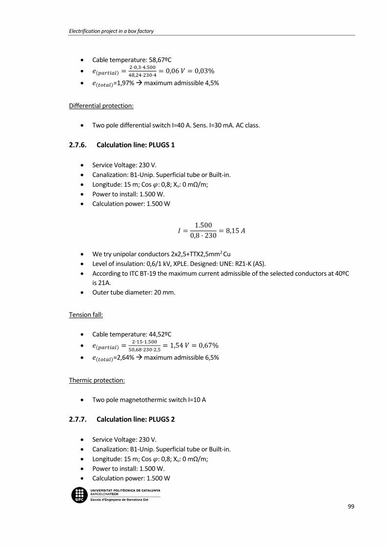
Electrification project in a box factory
99
Cable temperature: 58,67ºC
𝑒(𝑝𝑎𝑟𝑡𝑖𝑎𝑙) =2·0,3·4.500
48,24·230·4= 0,06 𝑉 = 0,03%
𝑒(𝑡𝑜𝑡𝑎𝑙)=1,97% maximum admissible 4,5%
Differential protection:
Two pole differential switch I=40 A. Sens. I=30 mA. AC class.
2.7.6. Calculation line: PLUGS 1
Service Voltage: 230 V.
Canalization: B1-Unip. Superficial tube or Built-in.
Longitude: 15 m; Cos 𝜑: 0,8; Xu: 0 mΩ/m;
Power to install: 1.500 W.
Calculation power: 1.500 W
𝐼 =1.500
0,8 · 230= 8,15 𝐴
We try unipolar conductors 2x2,5+TTX2,5mm2 Cu
Level of insulation: 0,6/1 kV, XPLE. Designed: UNE: RZ1-K (AS).
According to ITC BT-19 the maximum current admissible of the selected conductors at 40ºC
is 21A.
Outer tube diameter: 20 mm.
Tension fall:
Cable temperature: 44,52ºC
𝑒(𝑝𝑎𝑟𝑡𝑖𝑎𝑙) =2·15·1.500
50,68·230·2,5= 1,54 𝑉 = 0,67%
𝑒(𝑡𝑜𝑡𝑎𝑙)=2,64% maximum admissible 6,5%
Thermic protection:
Two pole magnetothermic switch I=10 A
2.7.7. Calculation line: PLUGS 2
Service Voltage: 230 V.
Canalization: B1-Unip. Superficial tube or Built-in.
Longitude: 15 m; Cos 𝜑: 0,8; Xu: 0 mΩ/m;
Power to install: 1.500 W.
Calculation power: 1.500 W

Memoria
100
𝐼 =1.500
0,8 · 230= 8,15 𝐴
We try unipolar conductors 2x2,5+TTX2,5mm2 Cu
Level of insulation: 0,6/1 kV, XPLE. Designed: UNE: RZ1-K (AS).
According to ITC BT-19 the maximum current admissible of the selected conductors at 40ºC
is 21A.
Outer tube diameter: 20 mm.
Tension fall:
Cable temperature: 44,52ºC
𝑒(𝑝𝑎𝑟𝑡𝑖𝑎𝑙) =2·15·1.500
50,68·230·2,5= 1,54 𝑉 = 0,67%
𝑒(𝑡𝑜𝑡𝑎𝑙)=2,64% maximum admissible 6,5%
Thermic protection:
Two pole magnetothermic switch I=10 A
2.7.8. Calculation line: PLUGS 3
Service Voltage: 230 V.
Canalization: B1-Unip. Superficial tube or Built-in.
Longitude: 15 m; Cos 𝜑: 0,8; Xu: 0 mΩ/m;
Power to install: 1.500 W.
Calculation power: 1.500 W
𝐼 =1.500
0,8 · 230= 8,15 𝐴
We try unipolar conductors 2x2,5+TTX2,5mm2 Cu
Level of insulation: 0,6/1 kV, XPLE. Designed: UNE: RZ1-K (AS).
According to ITC BT-19 the maximum current admissible of the selected conductors at 40ºC
is 21A.
Outer tube diameter: 20 mm.
Tension fall:
Cable temperature: 44,52ºC
𝑒(𝑝𝑎𝑟𝑡𝑖𝑎𝑙) =2·15·1.500
50,68·230·2,5= 1,54 𝑉 = 0,67%
𝑒(𝑡𝑜𝑡𝑎𝑙)=2,64% maximum admissible 6,5%

Electrification project in a box factory
101
Thermic protection:
Two pole magnetothermic switch I=10 A
2.7.9. Calculation line: PLUGS02
Service Voltage: 230 V.
Canalization: C-Unip. or Mult. on wall.
Longitude: 0,3 m; Cos 𝜑: 0,8; Xu: 0 mΩ/m;
Power to install: 4.500 W.
Simultaneity factor: 1.
Calculation power: 4.500 W
𝐼 =4.500
0,8 · 230= 24,46 𝐴
We try unipolar conductors 2x4mm2 Cu
Level of insulation: 0,6/1 V, XPLE. Designed: UNE: RZ1-K (AS).
According to ITC BT-19 the maximum current admissible of the selected conductors at 40ºC
is 31A.
Tension fall:
Cable temperature: 58,67ºC
𝑒(𝑝𝑎𝑟𝑡𝑖𝑎𝑙) =2·0,3·4.500
48,24·230·4= 0,06 𝑉 = 0,03%
𝑒(𝑡𝑜𝑡𝑎𝑙)=1,97% maximum admissible 4,5%
Differential protection:
Two pole differential switch I=40 A. Sens. I=30 mA. AC class.
2.7.10. Calculation line: PLUGS 4
Service Voltage: 230 V.
Canalization: B1-Unip. Superficial tube or Built-in.
Longitude: 15 m; Cos 𝜑: 0,8; Xu: 0 mΩ/m;
Power to install: 1.500 W.
Calculation power: 1.500 W
𝐼 =1.500
0,8 · 230= 8,15 𝐴

Memoria
102
We try unipolar conductors 2x2,5+TTX2,5mm2 Cu
Level of insulation: 0,6/1 kV, XPLE. Designed: UNE: RZ1-K (AS).
According to ITC BT-19 the maximum current admissible of the selected conductors at 40ºC
is 21A.
Outer tube diameter: 20 mm.
Tension fall:
Cable temperature: 44,52ºC
𝑒(𝑝𝑎𝑟𝑡𝑖𝑎𝑙) =2·15·1.500
50,68·230·2,5= 1,54 𝑉 = 0,67%
𝑒(𝑡𝑜𝑡𝑎𝑙)=2,64% maximum admissible 6,5%
Thermic protection:
Two pole magnetothermic switch I=10 A
2.7.11. Calculation line: CLI01
Service Voltage: 230 V.
Canalization: B1-Unip. Superficial tube or Built-in.
Longitude: 15 m; Cos 𝜑: 0,8; Xu: 0 mΩ/m;
Power to install: 1.500 W.
Calculation power: 1.500 W
𝐼 =1.500
0,8 · 230= 8,15 𝐴
We try unipolar conductors 2x2,5+TTX2,5mm2 Cu
Level of insulation: 0,6/1 kV, XPLE. Designed: UNE: RZ1-K (AS).
According to ITC BT-19 the maximum current admissible of the selected conductors at 40ºC
is 21A.
Outer tube diameter: 20 mm.
Tension fall:
Cable temperature: 44,52ºC
𝑒(𝑝𝑎𝑟𝑡𝑖𝑎𝑙) =2·15·1.500
50,68·230·2,5= 1,54 𝑉 = 0,67%
𝑒(𝑡𝑜𝑡𝑎𝑙)=2,64% maximum admissible 6,5%
Thermic protection:

Electrification project in a box factory
103
Two pole magnetothermic switch I=10 A
2.7.12. Calculation line: CLI02
Service Voltage: 230 V.
Canalization: B1-Unip. Superficial tube or Built-in.
Longitude: 15 m; Cos 𝜑: 0,8; Xu: 0 mΩ/m;
Power to install: 1.500 W.
Calculation power: 1.500 W
𝐼 =1.500
0,8 · 230= 8,15 𝐴
We try unipolar conductors 2x2,5+TTX2,5mm2 Cu
Level of insulation: 0,6/1 kV, XPLE. Designed: UNE: RZ1-K (AS).
According to ITC BT-19 the maximum current admissible of the selected conductors at 40ºC
is 21A.
Outer tube diameter: 20 mm.
Tension fall:
Cable temperature: 44,52ºC
𝑒(𝑝𝑎𝑟𝑡𝑖𝑎𝑙) =2·15·1.500
50,68·230·2,5= 1,54 𝑉 = 0,67%
𝑒(𝑡𝑜𝑡𝑎𝑙)=2,64% maximum admissible 6,5%
Thermic protection:
Two pole magnetothermic switch I=10 A
2.7.13. Bus Bar calculations: SP-WEATHER
Data
Metal: Cu.
State of the plates: Bare.
Number of plates per phase: 1.
Distance between plates: d=10 cm.
Distance between supports: L=25 cm.
Short circuit time: 0,5 s.
Used plate

Memoria
104
Section: 24 mm2.
Amplitude: 12 mm.
Thickness: 2 mm.
Wx, Ix, Wi, li (cm3, cm4): 0,048 ; 0,0288 ; 0,008; 0,0008.
I. admissible of the bus bar: 110 A.
a) Electrodynamic calculation
𝜎𝑚𝑎𝑥 =1,56
2 · 252
60 · 10 · 0,008 · 1= 315,775 ≤ 1200
𝑘𝑔
𝑐𝑚2 𝐶𝑢
b) Thermal calculation per admissible current
𝐼𝑐𝑎𝑙 = 17,5 𝐴
𝐼𝑎𝑑𝑚 = 110 𝐴
c) Check for thermal request in short circuit
𝐼𝑝𝑐𝑐 = 1,56 𝑘𝐴
𝐼𝑐𝑐𝑐𝑠 =𝐾𝑐 · 𝑆
1000 · √𝑡𝑐𝑐
=164 · 24
1000 · √0,5= 5,57 𝑘𝐴
2.8. Sub-panel SP-EMBA244
2.8.1. Power demand
-Total installed power:
BCR01 95.000 W
TIER01 4.000 W
CCM01 5.500 W
PALLMAC 7.374 W
GH01 736 W
CHAIN01 552 W
CHAIN02 552 W

Electrification project in a box factory
105
DIS01 736 W
ROLL01 552 W
ROLL02 552 W
FEEDER 18.000 W
2.8.2. Calculation line: BCR01
Service Voltage: 400 V.
Canalization: F-Unip. O Mult. Suporters.
Longitude: 20 m; Cos 𝜑: 0,9; Xu: 0 mΩ/m;R:1;
Power to install: 95.000 W.
Calculation power (according to ITC BT-44 and ITC BT-47):
𝑃 = 5.000 · 1,25 + 90.000 = 96.250 𝑊
𝐼 =96.250
0,9 · 400 · √3= 154,37𝐴
We try unipolar conductors 4x95+TTx50mm2 Cu
Level of insulation: 0,6/1 kV, XPLE. Designed: UNE: RZ1-K (AS).
According to ITC BT-19 the maximum current admissible of the selected conductors at 40ºC
is 271A.
Tension fall:
Cable temperature: 56,22ºC
𝑒(𝑝𝑎𝑟𝑡𝑖𝑎𝑙) =20·96.250
48,65·400·95= 1,04𝑉 = 0,26%
𝑒(𝑡𝑜𝑡𝑎𝑙)=1,37% maximum admissible 6,5%
Thermic protection:
Four pole automatic switch In: 250 A. Thermic regulation Ireg= 200 A.
Differential protection:
Relay and differential transformer sensitivity: 300mA. AC class.
2.8.3. Calculation line: EMBA244-1
Service Voltage: 400 V.

Memoria
106
Canalization: C-Unip. or Mult. on wall.
Longitude: 0,3 m; Cos 𝜑: 0,8; Xu: 0 mΩ/m;
Power to install: 9.500 W.
Simultaneity factor: 0,6.
Calculation power (according to ITC BT-47):
𝑃 = 5.500 · 1,25 + 200 = 7.075 𝑊
𝐼 =7.075
0,8 · 400 · √3= 12,77 𝐴
We try unipolar conductors 4x6mm2 Cu
Level of insulation: 0,6/1 V, XPLE. Designed: UNE: RZ1-K (AS).
According to ITC BT-19 the maximum current admissible of the selected conductors at 40ºC
is 36A.
Tension fall:
Cable temperature: 43,77ºC
𝑒(𝑝𝑎𝑟𝑡𝑖𝑎𝑙) =0,3·7.075
50,82·400·6= 0,02 𝑉 = 0%
𝑒(𝑡𝑜𝑡𝑎𝑙)=1,11% maximum admissible 4,5%
Differential protection:
Four pole differential switch I=40 A. Sens. I=30 mA. AC class.
2.8.4. Calculation line: TIER01
Service Voltage: 400 V.
Canalization: B1-Unip. Superficial tube or Built-in.
Longitude: 15 m; Cos 𝜑: 0,85; Xu: 0 mΩ/m; R: 1;
Power to install: 4.000 W.
Calculation power (according to ITC BT-47):
𝑃 = 4.000 · 1,25 = 5.000 𝑊
𝐼 =5.000
0,85 · 400 · √3 · 1= 8,49 𝐴
We try unipolar conductors 4x2,5+TTx2,5mm2 Cu
Level of insulation: 0,6/1 kV, XPLE. Designed: UNE: RZ1-K (AS).
According to ITC BT-19 the maximum current admissible of the selected conductors at 40ºC
is 18,5A.
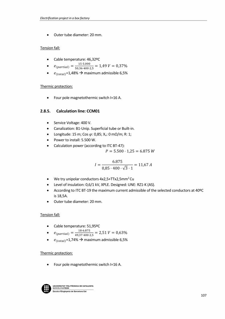
Electrification project in a box factory
107
Outer tube diameter: 20 mm.
Tension fall:
Cable temperature: 46,32ºC
𝑒(𝑝𝑎𝑟𝑡𝑖𝑎𝑙) =15·5.000
50,36·400·2,5= 1,49 𝑉 = 0,37%
𝑒(𝑡𝑜𝑡𝑎𝑙)=1,48% maximum admissible 6,5%
Thermic protection:
Four pole magnetothermic switch I=16 A.
2.8.5. Calculation line: CCM01
Service Voltage: 400 V.
Canalization: B1-Unip. Superficial tube or Built-in.
Longitude: 15 m; Cos 𝜑: 0,85; Xu: 0 mΩ/m; R: 1;
Power to install: 5.500 W.
Calculation power (according to ITC BT-47):
𝑃 = 5.500 · 1,25 = 6.875 𝑊
𝐼 =6.875
0,85 · 400 · √3 · 1= 11,67 𝐴
We try unipolar conductors 4x2,5+TTx2,5mm2 Cu
Level of insulation: 0,6/1 kV, XPLE. Designed: UNE: RZ1-K (AS).
According to ITC BT-19 the maximum current admissible of the selected conductors at 40ºC
is 18,5A.
Outer tube diameter: 20 mm.
Tension fall:
Cable temperature: 51,95ºC
𝑒(𝑝𝑎𝑟𝑡𝑖𝑎𝑙) =18·6.875
49,37·400·2,5= 2,51 𝑉 = 0,63%
𝑒(𝑡𝑜𝑡𝑎𝑙)=1,74% maximum admissible 6,5%
Thermic protection:
Four pole magnetothermic switch I=16 A.

Memoria
108
2.8.6. Calculation line: PALLMAC
Service Voltage: 400 V.
Canalization: B1-Unip. Superficial tube or Built-in.
Longitude: 18 m; Cos 𝜑: 0,85; Xu: 0 mΩ/m; R: 1;
Power to install: 7.374 W.
Calculation power (according to ITC BT-47):
𝑃 = 4.416 · 1,25 + 2.958 = 8.478 𝑊
𝐼 =8.478
0,85 · 400 · √3 · 1= 14,4 𝐴
We try unipolar conductors 4x16+TTx16mm2 Cu
Level of insulation: 0,6/1 kV, XPLE. Designed: UNE: RZ1-K (AS).
According to ITC BT-19 the maximum current admissible of the selected conductors at 40ºC
is 59A.
Outer tube diameter: 40 mm.
Tension fall:
Cable temperature: 41,79ºC
𝑒(𝑝𝑎𝑟𝑡𝑖𝑎𝑙) =18·8.478
51,18·400·16= 0,47 𝑉 = 0,12%
𝑒(𝑡𝑜𝑡𝑎𝑙)=1,22% maximum admissible 6,5%
Thermic protection:
Four pole magnetothermic switch I=50 A.
Differential protection:
Four pole differential switch I=63 A. Sens. I=30 mA. AC class.
2.8.7. Calculation line: EMBA244-2
Service Voltage: 400 V.
Canalization: C-Unip. or Mult. on wall.
Longitude: 0,3 m; Cos 𝜑: 0,8; Xu: 0 mΩ/m;
Power to install: 1.840 W.
Simultaneity factor: 1.
Calculation power (according to ITC BT-47):
Electrification project in a box factory
109
𝑃 = 736 · 1,25 + 1.104 = 2.024 𝑊
𝐼 =2.024
0,8 · 400 · √3= 3,65 𝐴
We try unipolar conductors 4x10mm2 Cu
Level of insulation: 0,6/1 V, XPLE. Designed: UNE: RZ1-K (AS).
According to ITC BT-19 the maximum current admissible of the selected conductors at 40ºC
is 50A.
Tension fall:
Cable temperature: 40,16ºC
𝑒(𝑝𝑎𝑟𝑡𝑖𝑎𝑙) =0,3·2.024
51,49·400·10= 0 𝑉 = 0%
𝑒(𝑡𝑜𝑡𝑎𝑙)=1,11% maximum admissible 4,5%
Differential protection:
Four pole differential switch I=63 A. Sens. I=30 mA. AC class.
2.8.8. Calculation line: GH01
Service Voltage: 400 V.
Canalization: B1-Unip. Superficial tube or Built-in.
Longitude: 12 m; Cos 𝜑: 0,85; Xu: 0 mΩ/m; R: 1;
Power to install: 736 W.
Calculation power (according to ITC BT-47):
𝑃 = 736 · 1,25 = 920 𝑊
𝐼 =920
0,85 · 400 · √3 · 1= 1,56 𝐴
We try unipolar conductors 4x2,5+TTx2,5mm2 Cu
Level of insulation: 0,6/1 kV, XPLE. Designed: UNE: RZ1-K (AS).
According to ITC BT-19 the maximum current admissible of the selected conductors at 40ºC
is 18,5A.
Outer tube diameter: 20 mm.
Tension fall:
Cable temperature: 40,21ºC

Memoria
110
𝑒(𝑝𝑎𝑟𝑡𝑖𝑎𝑙) =12·920
51,48·400·2,5= 0,21 𝑉 = 0,05%
𝑒(𝑡𝑜𝑡𝑎𝑙)=1,16% maximum admissible 6,5%
Thermic protection:
Four pole magnetothermic switch I=16 A.
2.8.9. Calculation line: CHAIN01
Service Voltage: 400 V.
Canalization: B1-Unip. Superficial tube or Built-in.
Longitude: 15 m; Cos 𝜑: 0,85; Xu: 0 mΩ/m; R: 1;
Power to install: 552 W.
Calculation power (according to ITC BT-47):
𝑃 = 552 · 1,25 = 690 𝑊
𝐼 =690
0,85 · 400 · √3 · 1= 1,17 𝐴
We try unipolar conductors 4x2,5+TTx2,5mm2 Cu
Level of insulation: 0,6/1 kV, XPLE. Designed: UNE: RZ1-K (AS).
According to ITC BT-19 the maximum current admissible of the selected conductors at 40ºC
is 18,5A.
Outer tube diameter: 20 mm.
Tension fall:
Cable temperature: 40,12ºC
𝑒(𝑝𝑎𝑟𝑡𝑖𝑎𝑙) =15·690
51,49·400·2,5= 0,2 𝑉 = 0,05%
𝑒(𝑡𝑜𝑡𝑎𝑙)=1,16% maximum admissible 6,5%
Thermic protection:
Four pole magnetothermic switch I=16 A.
2.8.10. Calculation line: CHAIN02
Service Voltage: 400 V.
Canalization: B1-Unip. Superficial tube or Built-in.
Longitude: 18 m; Cos 𝜑: 0,85; Xu: 0 mΩ/m; R: 1;
Power to install: 552 W.

Electrification project in a box factory
111
Calculation power (according to ITC BT-47):
𝑃 = 552 · 1,25 = 690 𝑊
𝐼 =690
0,85 · 400 · √3 · 1= 1,17 𝐴
We try unipolar conductors 4x2,5+TTx2,5mm2 Cu
Level of insulation: 0,6/1 kV, XPLE. Designed: UNE: RZ1-K (AS).
According to ITC BT-19 the maximum current admissible of the selected conductors at 40ºC
is 18,5A.
Outer tube diameter: 20 mm.
Tension fall:
Cable temperature: 40,12ºC
𝑒(𝑝𝑎𝑟𝑡𝑖𝑎𝑙) =18·690
51,49·400·2,5= 0,24 𝑉 = 0,06%
𝑒(𝑡𝑜𝑡𝑎𝑙)=1,17% maximum admissible 6,5%
Thermic protection:
Four pole magnetothermic switch I=16 A.
2.8.11. Calculation line: EMBA244-3
Service Voltage: 400 V.
Canalization: C-Unip. or Mult. on wall.
Longitude: 0,3 m; Cos 𝜑: 0,8; Xu: 0 mΩ/m;
Power to install: 1.840 W.
Simultaneity factor: 0,8.
Calculation power (according to ITC BT-47):
𝑃 = 736 · 1,25 + 736 = 1.656 𝑊
𝐼 =1.656
0,8 · 400 · √3= 2,99 𝐴
We try unipolar conductors 4x10mm2 Cu
Level of insulation: 0,6/1 V, XPLE. Designed: UNE: RZ1-K (AS).
According to ITC BT-19 the maximum current admissible of the selected conductors at 40ºC
is 50A.
Memoria
112
Tension fall:
Cable temperature: 40,11ºC
𝑒(𝑝𝑎𝑟𝑡𝑖𝑎𝑙) =0,3·1.656
51,5·400·10= 0 𝑉 = 0%
𝑒(𝑡𝑜𝑡𝑎𝑙)=1,11% maximum admissible 4,5%
Differential protection:
Four pole differential switch I=63 A. Sens. I=30 mA. AC class.
2.8.12. Calculation line: DIS01
Service Voltage: 400 V.
Canalization: B1-Unip. Superficial tube or Built-in.
Longitude: 18 m; Cos 𝜑: 0,85; Xu: 0 mΩ/m; R: 1;
Power to install: 736 W.
Calculation power (according to ITC BT-47):
𝑃 = 736 · 1,25 = 920 𝑊
𝐼 =920
0,85 · 400 · √3 · 1= 1,56 𝐴
We try unipolar conductors 4x2,5+TTx2,5mm2 Cu
Level of insulation: 0,6/1 kV, XPLE. Designed: UNE: RZ1-K (AS).
According to ITC BT-19 the maximum current admissible of the selected conductors at 40ºC
is 18,5A.
Outer tube diameter: 20 mm.
Tension fall:
Cable temperature: 40,21ºC
𝑒(𝑝𝑎𝑟𝑡𝑖𝑎𝑙) =18·920
51,48·400·2,5= 0,32 𝑉 = 0,08%
𝑒(𝑡𝑜𝑡𝑎𝑙)=1,19% maximum admissible 6,5%
Thermic protection:
Four pole magnetothermic switch I=16 A.
2.8.13. Calculation line: ROLL01
Service Voltage: 400 V.
Electrification project in a box factory
113
Canalization: B1-Unip. Superficial tube or Built-in.
Longitude: 18 m; Cos 𝜑: 0,85; Xu: 0 mΩ/m; R: 1;
Power to install: 552 W.
Calculation power (according to ITC BT-47):
𝑃 = 552 · 1,25 = 690 𝑊
𝐼 =690
0,85 · 400 · √3 · 1= 1,17 𝐴
We try unipolar conductors 4x2,5+TTx2,5mm2 Cu
Level of insulation: 0,6/1 kV, XPLE. Designed: UNE: RZ1-K (AS).
According to ITC BT-19 the maximum current admissible of the selected conductors at 40ºC
is 18,5A.
Outer tube diameter: 20 mm.
Tension fall:
Cable temperature: 40,12ºC
𝑒(𝑝𝑎𝑟𝑡𝑖𝑎𝑙) =18·690
51,49·400·2,5= 0,24 𝑉 = 0,06%
𝑒(𝑡𝑜𝑡𝑎𝑙)=1,17% maximum admissible 6,5%
Thermic protection:
Four pole magnetothermic switch I=16 A.
2.8.14. Calculation line: ROLL02
Service Voltage: 400 V.
Canalization: B1-Unip. Superficial tube or Built-in.
Longitude: 18 m; Cos 𝜑: 0,85; Xu: 0 mΩ/m; R: 1;
Power to install: 552 W.
Calculation power (according to ITC BT-47):
𝑃 = 552 · 1,25 = 690 𝑊
𝐼 =690
0,85 · 400 · √3 · 1= 1,17 𝐴
We try unipolar conductors 4x2,5+TTx2,5mm2 Cu
Level of insulation: 0,6/1 kV, XPLE. Designed: UNE: RZ1-K (AS).
According to ITC BT-19 the maximum current admissible of the selected conductors at 40ºC
is 18,5A.
Outer tube diameter: 20 mm.
Memoria
114
Tension fall:
Cable temperature: 40,12ºC
𝑒(𝑝𝑎𝑟𝑡𝑖𝑎𝑙) =18·690
51,49·400·2,5= 0,24 𝑉 = 0,06%
𝑒(𝑡𝑜𝑡𝑎𝑙)=1,17% maximum admissible 6,5%
Thermic protection:
Four pole magnetothermic switch I=16 A.
2.8.15. Calculation line: FEEDER
Service Voltage: 400 V.
Canalization: B1-Unip. Superficial tube or Built-in.
Longitude: 19 m; Cos 𝜑: 0,85; Xu: 0 mΩ/m; R: 1;
Power to install: 18.000 W.
Calculation power (according to ITC BT-47):
𝑃 = 5.000 · 1,25 + 13.000 = 19.250 𝑊
𝐼 =19.250
0,85 · 400 · √3 · 1= 32,69 𝐴
We try unipolar conductors 4x10+TTx10mm2 Cu
Level of insulation: 0,6/1 kV, XPLE. Designed: UNE: RZ1-K (AS).
According to ITC BT-19 the maximum current admissible of the selected conductors at 40ºC
is 44A.
Outer tube diameter: 32 mm.
Tension fall:
Cable temperature: 56,56ºC
𝑒(𝑝𝑎𝑟𝑡𝑖𝑎𝑙) =19·19.250
48,59·400·10= 1,88 𝑉 = 0,47%
𝑒(𝑡𝑜𝑡𝑎𝑙)=1,58% maximum admissible 6,5%
Thermic protection:
Four pole magnetothermic switch I=40 A.
Differential protection:
Four pole differential switch I=40 A. Sens. I=30 mA. AC class

Electrification project in a box factory
115
2.8.16. Bus Bar calculations: SP-EMBA244
Data
Metal: Cu.
State of the plates: Bare.
Number of plates per phase: 1.
Distance between plates: d=10 cm.
Distance between supports: L=25 cm.
Short circuit time: 0,5 s.
Used plate
Section: 100 mm2.
Amplitude: 20 mm.
Thickness: 5 mm.
Wx, Ix, Wi, li (cm3, cm4): 0,333 ; 0,333 ; 0,083; 0,0208.
I. admissible of the bus bar: 290 A.
a) Electrodynamic calculation
𝜎𝑚𝑎𝑥 =9,75
2 · 252
60 · 10 · 0,083 · 1= 1.192,009 ≤ 1200
𝑘𝑔
𝑐𝑚2 𝐶𝑢
b) Thermal calculation per admissible current
𝐼𝑐𝑎𝑙 = 147,06 𝐴
𝐼𝑎𝑑𝑚 = 290 𝐴
c) Check for thermal request in short circuit
𝐼𝑝𝑐𝑐 = 9,75 𝑘𝐴
𝐼𝑐𝑐𝑐𝑠 =𝐾𝑐 · 𝑆
1000 · √𝑡𝑐𝑐
=164 · 100
1000 · √0,5= 23,19 𝑘𝐴

Memoria
116
2.9. Sub-panel SP-EMA170
2.9.1. Power demand
-Total installed power:
BCR01 105.000 W
ELEVATOR 1.500 W
TIER01 4.000 W
ROBOT 25.000 W
HYDELEVATOR01 750 W
ROLL01 2.250 W
HYDELEVATOR02 1.500 W
FEEDER 18.000 W
ROLL02 2.250 W
ROLL03 2.250 W
ROLL04 2.250 W
2.9.2. Calculation line: BCR01
Service Voltage: 400 V.
Canalization: F-Unip. O Mult. Suporters.
Longitude: 20 m; Cos 𝜑: 0,85; Xu: 0 mΩ/m;R:1;
Power to install: 105.000 W.
Simultaneity factor: 0,6
Calculation power (according to ITC BT-47):
𝑃 = 5.000 · 1,25 + 100.000 = 106.250 𝑊
𝐼 =106.250
0,85 · 400 · √3= 180,43 𝐴
We try unipolar conductors 4x95+TTx50mm2 Cu
Level of insulation: 0,6/1 kV, XPLE. Designed: UNE: RZ1-K (AS).
Electrification project in a box factory
117
According to ITC BT-19 the maximum current admissible of the selected conductors at 40ºC
is 271A.
Tension fall:
Cable temperature: 62,16ºC
𝑒(𝑝𝑎𝑟𝑡𝑖𝑎𝑙) =20·106.250
47,68·400·95= 1,17𝑉 = 0,29%
𝑒(𝑡𝑜𝑡𝑎𝑙)=1,56% maximum admissible 6,5%
Thermic protection:
Four pole automatic switch In: 250 A. Thermic regulation Ireg= 226 A.
Differential protection:
Relay and differential transformer sensitivity: 300mA. AC class [s].
2.9.3. Calculation line: EMBA170 1
Service Voltage: 400 V.
Canalization: C-Unip. or Mult. on wall.
Longitude: 0,3 m; Cos 𝜑: 0,8; Xu: 0 mΩ/m;
Power to install: 5.500 W.
Simultaneity factor: 1.
Calculation power (according to ITC BT-47):
𝑃 = 4.000 · 1,25 + 1.500 = 6.500 𝑊
𝐼 =6.500
0,8 · 400 · √3= 11,73 𝐴
We try unipolar conductors 4x6mm2 Cu
Level of insulation: 0,6/1 V, XPLE. Designed: UNE: RZ1-K (AS).
According to ITC BT-19 the maximum current admissible of the selected conductors at 40ºC
is 36A.
Tension fall:
Cable temperature: 43,18ºC
𝑒(𝑝𝑎𝑟𝑡𝑖𝑎𝑙) =0,3·6.500
50,93·400·6= 0,02 𝑉 = 0%

Memoria
118
𝑒(𝑡𝑜𝑡𝑎𝑙)=1,27% maximum admissible 4,5%
Differential protection:
Four pole differential switch I=40 A. Sens. I=30 mA. AC class.
2.9.4. Calculation line: ELEVATOR
Service Voltage: 400 V.
Canalization: B1-Unip. Superficial tube or Built-in.
Longitude: 25 m; Cos 𝜑: 0,85; Xu: 0 mΩ/m; R: 1;
Power to install: 1.500 W.
Calculation power (according to ITC BT-47):
𝑃 = 1.500 · 1,25 = 1.875 𝑊
𝐼 =1.875
0,85 · 400 · √3 · 1= 3,18 𝐴
We try unipolar conductors 4x2,5+TTx2,5mm2 Cu
Level of insulation: 0,6/1 kV, XPLE. Designed: UNE: RZ1-K (AS).
According to ITC BT-19 the maximum current admissible of the selected conductors at 40ºC
is 18,5A.
Outer tube diameter: 20 mm.
Tension fall:
Cable temperature: 40,89ºC
𝑒(𝑝𝑎𝑟𝑡𝑖𝑎𝑙) =25·1.875
51,53·400·2,5= 0,91 𝑉 = 0,23%
𝑒(𝑡𝑜𝑡𝑎𝑙)=1,5% maximum admissible 6,5%
Thermic protection:
Four pole magnetothermic switch I=16 A.
2.9.5. Calculation line: TIER01
Service Voltage: 400 V.
Canalization: B1-Unip. Superficial tube or Built-in.
Longitude: 30 m; Cos 𝜑: 0,85; Xu: 0 mΩ/m; R: 1;
Power to install: 4.000 W.
Calculation power (according to ITC BT-47):
𝑃 = 4.000 · 1,25 = 5.000 𝑊
Electrification project in a box factory
119
𝐼 =5.000
0,85 · 400 · √3 · 1= 8,49 𝐴
We try unipolar conductors 4x2,5+TTx2,5mm2 Cu
Level of insulation: 0,6/1 kV, XPLE. Designed: UNE: RZ1-K (AS).
According to ITC BT-19 the maximum current admissible of the selected conductors at 40ºC
is 18,5A.
Outer tube diameter: 20 mm.
Tension fall:
Cable temperature: 46,32ºC
𝑒(𝑝𝑎𝑟𝑡𝑖𝑎𝑙) =30·5.000
50,36·400·2,5= 2,98 𝑉 = 0,74%
𝑒(𝑡𝑜𝑡𝑎𝑙)=2,02% maximum admissible 6,5%
Thermic protection:
Four pole magnetothermic switch I=16 A.
2.9.6. Calculation line: ROBOT
Service Voltage: 400 V.
Canalization: B1-Unip. Superficial tube or Built-in.
Longitude: 18 m; Cos 𝜑: 0,85; Xu: 0 mΩ/m; R: 1;
Power to install: 25.000 W.
Calculation power (according to ITC BT-47):
𝑃 = 5.000 · 1,25 + 20.000 = 26.250 𝑊
𝐼 =26.250
0,85 · 400 · √3 · 1= 44,58 𝐴
We try unipolar conductors 4x16+TTx16mm2 Cu
Level of insulation: 0,6/1 kV, XPLE. Designed: UNE: RZ1-K (AS).
According to ITC BT-19 the maximum current admissible of the selected conductors at 40ºC
is 59A.
Outer tube diameter: 40 mm.
Tension fall:
Cable temperature: 57,12ºC
𝑒(𝑝𝑎𝑟𝑡𝑖𝑎𝑙) =18·26.250
48,5·400·16= 1,52 𝑉 = 0,38%

Memoria
120
𝑒(𝑡𝑜𝑡𝑎𝑙)=1,65% maximum admissible 6,5%
Thermic protection:
Four pole magnetothermic switch I=50 A.
Differential protection:
Four pole differential switch I=63 A. Sens. I=30 mA. AC class.
2.9.7. Calculation line: EMBA170 2
Service Voltage: 400 V.
Canalization: C-Unip. or Mult. on wall.
Longitude: 0,3 m; Cos 𝜑: 0,8; Xu: 0 mΩ/m;
Power to install: 4.500 W.
Simultaneity factor: 1.
Calculation power (according to ITC BT-47):
𝑃 = 2.250 · 1,25 + 2.250 = 5.062,5 𝑊
𝐼 =5.062,5
0,8 · 400 · √3= 9,13 𝐴
We try unipolar conductors 4x10mm2 Cu
Level of insulation: 0,6/1 V, XPLE. Designed: UNE: RZ1-K (AS).
According to ITC BT-19 the maximum current admissible of the selected conductors at 40ºC
is 50A.
Tension fall:
Cable temperature: 41ºC
𝑒(𝑝𝑎𝑟𝑡𝑖𝑎𝑙) =0,3·5.062,5
51,33·400·10= 0,01 𝑉 = 0%
𝑒(𝑡𝑜𝑡𝑎𝑙)=1,27% maximum admissible 4,5%
Differential protection:
Four pole differential switch I=63 A. Sens. I=30 mA. AC class.
Electrification project in a box factory
121
2.9.8. Calculation line: HYDELEVATOR01
Service Voltage: 400 V.
Canalization: B1-Unip. Superficial tube or Built-in.
Longitude: 12 m; Cos 𝜑: 0,85; Xu: 0 mΩ/m; R: 1;
Power to install: 750 W.
Calculation power (according to ITC BT-47):
𝑃 = 750 · 1,25 = 937 𝑊
𝐼 =937
0,85 · 400 · √3 · 1= 1,59 𝐴
We try unipolar conductors 4x2,5+TTx2,5mm2 Cu
Level of insulation: 0,6/1 kV, XPLE. Designed: UNE: RZ1-K (AS).
According to ITC BT-19 the maximum current admissible of the selected conductors at 40ºC
is 18,5A.
Outer tube diameter: 20 mm.
Tension fall:
Cable temperature: 40,22ºC
𝑒(𝑝𝑎𝑟𝑡𝑖𝑎𝑙) =12·937
51,48·400·2,5= 0,22 𝑉 = 0,05%
𝑒(𝑡𝑜𝑡𝑎𝑙)=1,33% maximum admissible 6,5%
Thermic protection:
Four pole magnetothermic switch I=16 A.
2.9.9. Calculation line: ROLL01
Service Voltage: 400 V.
Canalization: B1-Unip. Superficial tube or Built-in.
Longitude: 15 m; Cos 𝜑: 0,85; Xu: 0 mΩ/m; R: 1;
Power to install: 2.250 W.
Calculation power (according to ITC BT-47):
𝑃 = 2.250 · 1,25 = 2.812,5 𝑊
𝐼 =2.812,5
0,85 · 400 · √3 · 1= 4,78 𝐴
We try unipolar conductors 4x2,5+TTx2,5mm2 Cu
Level of insulation: 0,6/1 kV, XPLE. Designed: UNE: RZ1-K (AS).

Memoria
122
According to ITC BT-19 the maximum current admissible of the selected conductors at 40ºC
is 18,5A.
Outer tube diameter: 20 mm.
Tension fall:
Cable temperature: 42ºC
𝑒(𝑝𝑎𝑟𝑡𝑖𝑎𝑙) =15·2.812,5
51,14·400·2,5= 0,82 𝑉 = 0,21%
𝑒(𝑡𝑜𝑡𝑎𝑙)=1,48% maximum admissible 6,5%
Thermic protection:
Four pole magnetothermic switch I=16 A.
2.9.10. Calculation line: HYDELEVATOR02
Service Voltage: 400 V.
Canalization: B1-Unip. Superficial tube or Built-in.
Longitude: 18 m; Cos 𝜑: 0,85; Xu: 0 mΩ/m; R: 1;
Power to install: 1.500 W.
Calculation power (according to ITC BT-47):
𝑃 = 1.500 · 1,25 = 1.875 𝑊
𝐼 =1.875
0,85 · 400 · √3 · 1= 3,18 𝐴
We try unipolar conductors 4x2,5+TTx2,5mm2 Cu
Level of insulation: 0,6/1 kV, XPLE. Designed: UNE: RZ1-K (AS).
According to ITC BT-19 the maximum current admissible of the selected conductors at 40ºC
is 18,5A.
Outer tube diameter: 20 mm.
Tension fall:
Cable temperature: 40,89ºC
𝑒(𝑝𝑎𝑟𝑡𝑖𝑎𝑙) =18·1.875
51,35·400·2,5= 0,66 𝑉 = 0,16%
𝑒(𝑡𝑜𝑡𝑎𝑙)=1,44% maximum admissible 6,5%
Thermic protection:
Four pole magnetothermic switch I=16 A.
Electrification project in a box factory
123
2.9.11. Calculation line: FEEDER
Service Voltage: 400 V.
Canalization: B1-Unip. Superficial tube or Built-in.
Longitude: 19 m; Cos 𝜑: 0,85; Xu: 0 mΩ/m; R: 1;
Power to install: 18.000 W.
Calculation power (according to ITC BT-47):
𝑃 = 5.000 · 1,25 + 13.000 = 19.250 𝑊
𝐼 =19.250
0,85 · 400 · √3 · 1= 32,69 𝐴
We try unipolar conductors 4x10+TTx10mm2 Cu
Level of insulation: 0,6/1 kV, XPLE. Designed: UNE: RZ1-K (AS).
According to ITC BT-19 the maximum current admissible of the selected conductors at 40ºC
is 44A.
Outer tube diameter: 32 mm.
Tension fall:
Cable temperature: 56,56ºC
𝑒(𝑝𝑎𝑟𝑡𝑖𝑎𝑙) =19·19.250
48,59·400·10= 1,88 𝑉 = 0,47%
𝑒(𝑡𝑜𝑡𝑎𝑙)=1,74% maximum admissible 6,5%
Thermic protection:
Four pole magnetothermic switch I=40 A.
Differential protection:
Four pole differential switch I=40 A. Sens. I=30 mA. AC class
2.9.12. Calculation line: EMBA170 3
Service Voltage: 400 V.
Canalization: C-Unip. or Mult. on wall.
Longitude: 0,3 m; Cos 𝜑: 0,8; Xu: 0 mΩ/m;
Power to install: 6.750 W.
Simultaneity factor: 0,8.
Calculation power (according to ITC BT-47):

Memoria
124
𝑃 = 2.250 · 1,25 + 3.150 = 5.962,5 𝑊
𝐼 =5.962,5
0,8 · 400 · √3= 10,76 𝐴
We try unipolar conductors 4x10mm2 Cu
Level of insulation: 0,6/1 V, XPLE. Designed: UNE: RZ1-K (AS).
According to ITC BT-19 the maximum current admissible of the selected conductors at 40ºC
is 50A.
Tension fall:
Cable temperature: 41,39ºC
𝑒(𝑝𝑎𝑟𝑡𝑖𝑎𝑙) =0,3·5.962,5
51,33·400·10= 0,01 𝑉 = 0%
𝑒(𝑡𝑜𝑡𝑎𝑙)=1,27% maximum admissible 4,5%
Differential protection:
Four pole differential switch I=63 A. Sens. I=30 mA. AC class.
2.9.13. Calculation line: ROLL02
Service Voltage: 400 V.
Canalization: B1-Unip. Superficial tube or Built-in.
Longitude: 20 m; Cos 𝜑: 0,85; Xu: 0 mΩ/m; R: 1;
Power to install: 2.250 W.
Calculation power (according to ITC BT-47):
𝑃 = 2.250 · 1,25 = 2.812,5 𝑊
𝐼 =2.812,5
0,85 · 400 · √3 · 1= 4,78 𝐴
We try unipolar conductors 4x2,5+TTx2,5mm2 Cu
Level of insulation: 0,6/1 kV, XPLE. Designed: UNE: RZ1-K (AS).
According to ITC BT-19 the maximum current admissible of the selected conductors at 40ºC
is 18,5A.
Outer tube diameter: 20 mm.
Tension fall:
Cable temperature: 42ºC

Electrification project in a box factory
125
𝑒(𝑝𝑎𝑟𝑡𝑖𝑎𝑙) =20·2.812,5
51,14·400·2,5= 1,1 𝑉 = 0,27%
𝑒(𝑡𝑜𝑡𝑎𝑙)=1,55% maximum admissible 6,5%
Thermic protection:
Four pole magnetothermic switch I=16 A.
2.9.14. Calculation line: ROLL03
Service Voltage: 400 V.
Canalization: B1-Unip. Superficial tube or Built-in.
Longitude: 20 m; Cos 𝜑: 0,85; Xu: 0 mΩ/m; R: 1;
Power to install: 2.250 W.
Calculation power (according to ITC BT-47):
𝑃 = 2.250 · 1,25 = 2.812,5 𝑊
𝐼 =2.812,5
0,85 · 400 · √3 · 1= 4,78 𝐴
We try unipolar conductors 4x2,5+TTx2,5mm2 Cu
Level of insulation: 0,6/1 kV, XPLE. Designed: UNE: RZ1-K (AS).
According to ITC BT-19 the maximum current admissible of the selected conductors at 40ºC
is 18,5A.
Outer tube diameter: 20 mm.
Tension fall:
Cable temperature: 42ºC
𝑒(𝑝𝑎𝑟𝑡𝑖𝑎𝑙) =20·2.812,5
51,14·400·2,5= 1,1 𝑉 = 0,27%
𝑒(𝑡𝑜𝑡𝑎𝑙)=1,55% maximum admissible 6,5%
Thermic protection:
Four pole magnetothermic switch I=16 A.
2.9.15. Calculation line: ROLL04
Service Voltage: 400 V.
Canalization: B1-Unip. Superficial tube or Built-in.
Longitude: 20 m; Cos 𝜑: 0,85; Xu: 0 mΩ/m; R: 1;
Power to install: 2.250 W.

Memoria
126
Calculation power (according to ITC BT-47):
𝑃 = 2.250 · 1,25 = 2.812,5 𝑊
𝐼 =2.812,5
0,85 · 400 · √3 · 1= 4,78 𝐴
We try unipolar conductors 4x2,5+TTx2,5mm2 Cu
Level of insulation: 0,6/1 kV, XPLE. Designed: UNE: RZ1-K (AS).
According to ITC BT-19 the maximum current admissible of the selected conductors at 40ºC
is 18,5A.
Outer tube diameter: 20 mm.
Tension fall:
Cable temperature: 42ºC
𝑒(𝑝𝑎𝑟𝑡𝑖𝑎𝑙) =20·2.812,5
51,14·400·2,5= 1,1 𝑉 = 0,27%
𝑒(𝑡𝑜𝑡𝑎𝑙)=1,55% maximum admissible 6,5%
Thermic protection:
Four pole magnetothermic switch I=16 A.
2.9.16. Bus Bar calculations: SP-EMBA170
Data
Metal: Cu.
State of the plates: Bare.
Number of plates per phase: 1.
Distance between plates: d=10 cm.
Distance between supports: L=25 cm.
Short circuit time: 0,5 s.
Used plate
Section: 100 mm2.
Amplitude: 20 mm.
Thickness: 5 mm.
Wx, Ix, Wi, li (cm3, cm4): 0,333 ; 0,333 ; 0,083; 0,0208.
I. admissible of the bus bar: 290 A.

Electrification project in a box factory
127
a) Electrodynamic calculation
𝜎𝑚𝑎𝑥 =9,52
2 · 252
60 · 10 · 0,083 · 1= 1.138,346 ≤ 1200
𝑘𝑔
𝑐𝑚2 𝐶𝑢
b) Thermal calculation per admissible current
𝐼𝑐𝑎𝑙 = 180,61 𝐴
𝐼𝑎𝑑𝑚 = 290 𝐴
c) Check for thermal request in short circuit
𝐼𝑝𝑐𝑐 = 9,52 𝑘𝐴
𝐼𝑐𝑐𝑐𝑠 =𝐾𝑐 · 𝑆
1000 · √𝑡𝑐𝑐
=164 · 100
1000 · √0,5= 23,19 𝑘𝐴
2.10. Sub-panel SP-PROD1
2.10.1. Power demand
-Total installed power:
STR01 9.400 W
STR02 9.400 W
BALER01 5.250 W
BALER02 5.250 W
SEM01 500 W
BIMA01 5.250 W
PAMA01 2.944 W
EBR01 1.200 W
ROLL01 5.150 W
ROLL02 5.150 W
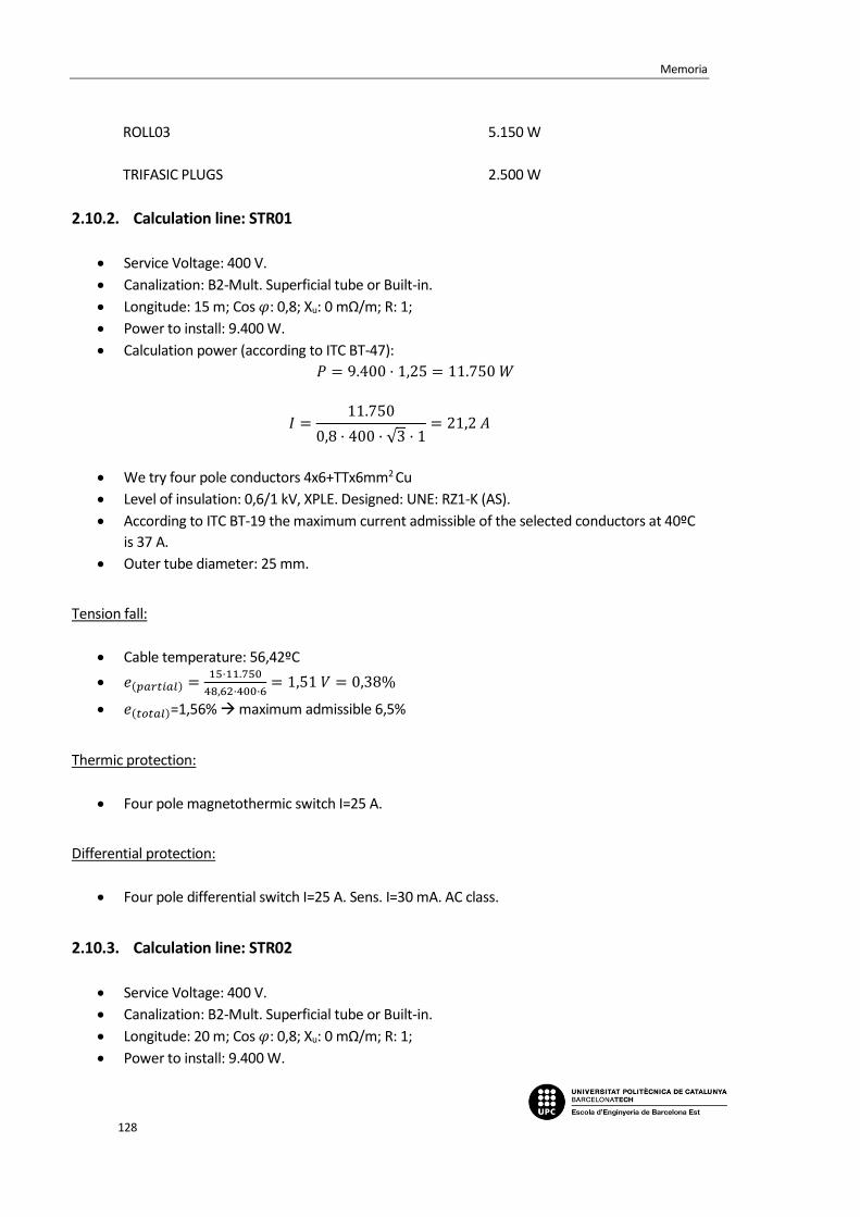
Memoria
128
ROLL03 5.150 W
TRIFASIC PLUGS 2.500 W
2.10.2. Calculation line: STR01
Service Voltage: 400 V.
Canalization: B2-Mult. Superficial tube or Built-in.
Longitude: 15 m; Cos 𝜑: 0,8; Xu: 0 mΩ/m; R: 1;
Power to install: 9.400 W.
Calculation power (according to ITC BT-47):
𝑃 = 9.400 · 1,25 = 11.750 𝑊
𝐼 =11.750
0,8 · 400 · √3 · 1= 21,2 𝐴
We try four pole conductors 4x6+TTx6mm2 Cu
Level of insulation: 0,6/1 kV, XPLE. Designed: UNE: RZ1-K (AS).
According to ITC BT-19 the maximum current admissible of the selected conductors at 40ºC
is 37 A.
Outer tube diameter: 25 mm.
Tension fall:
Cable temperature: 56,42ºC
𝑒(𝑝𝑎𝑟𝑡𝑖𝑎𝑙) =15·11.750
48,62·400·6= 1,51 𝑉 = 0,38%
𝑒(𝑡𝑜𝑡𝑎𝑙)=1,56% maximum admissible 6,5%
Thermic protection:
Four pole magnetothermic switch I=25 A.
Differential protection:
Four pole differential switch I=25 A. Sens. I=30 mA. AC class.
2.10.3. Calculation line: STR02
Service Voltage: 400 V.
Canalization: B2-Mult. Superficial tube or Built-in.
Longitude: 20 m; Cos 𝜑: 0,8; Xu: 0 mΩ/m; R: 1;
Power to install: 9.400 W.
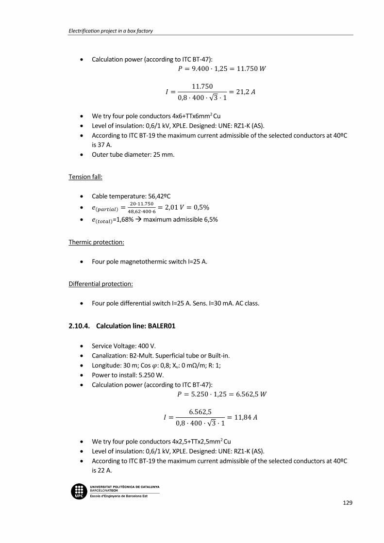
Electrification project in a box factory
129
Calculation power (according to ITC BT-47):
𝑃 = 9.400 · 1,25 = 11.750 𝑊
𝐼 =11.750
0,8 · 400 · √3 · 1= 21,2 𝐴
We try four pole conductors 4x6+TTx6mm2 Cu
Level of insulation: 0,6/1 kV, XPLE. Designed: UNE: RZ1-K (AS).
According to ITC BT-19 the maximum current admissible of the selected conductors at 40ºC
is 37 A.
Outer tube diameter: 25 mm.
Tension fall:
Cable temperature: 56,42ºC
𝑒(𝑝𝑎𝑟𝑡𝑖𝑎𝑙) =20·11.750
48,62·400·6= 2,01 𝑉 = 0,5%
𝑒(𝑡𝑜𝑡𝑎𝑙)=1,68% maximum admissible 6,5%
Thermic protection:
Four pole magnetothermic switch I=25 A.
Differential protection:
Four pole differential switch I=25 A. Sens. I=30 mA. AC class.
2.10.4. Calculation line: BALER01
Service Voltage: 400 V.
Canalization: B2-Mult. Superficial tube or Built-in.
Longitude: 30 m; Cos 𝜑: 0,8; Xu: 0 mΩ/m; R: 1;
Power to install: 5.250 W.
Calculation power (according to ITC BT-47):
𝑃 = 5.250 · 1,25 = 6.562,5 𝑊
𝐼 =6.562,5
0,8 · 400 · √3 · 1= 11,84 𝐴
We try four pole conductors 4x2,5+TTx2,5mm2 Cu
Level of insulation: 0,6/1 kV, XPLE. Designed: UNE: RZ1-K (AS).
According to ITC BT-19 the maximum current admissible of the selected conductors at 40ºC
is 22 A.

Memoria
130
Outer tube diameter: 20 mm.
Tension fall:
Cable temperature: 54,48ºC
𝑒(𝑝𝑎𝑟𝑡𝑖𝑎𝑙) =30·6.562,5
48,94·400·2,5= 4,02 𝑉 = 1,01%
𝑒(𝑡𝑜𝑡𝑎𝑙)=2,18% maximum admissible 6,5%
Thermic protection:
Four pole magnetothermic switch I=16 A.
Differential protection:
Four pole differential switch I=25 A. Sens. I=30 mA. AC class.
2.10.5. Calculation line: BALER02
Service Voltage: 400 V.
Canalization: B2-Mult. Superficial tube or Built-in.
Longitude: 25 m; Cos 𝜑: 0,8; Xu: 0 mΩ/m; R: 1;
Power to install: 5.250 W.
Calculation power (according to ITC BT-47):
𝑃 = 5.250 · 1,25 = 6.562,5 𝑊
𝐼 =6.562,5
0,8 · 400 · √3 · 1= 11,84 𝐴
We try four pole conductors 4x2,5+TTx2,5mm2 Cu
Level of insulation: 0,6/1 kV, XPLE. Designed: UNE: RZ1-K (AS).
According to ITC BT-19 the maximum current admissible of the selected conductors at 40ºC
is 22 A.
Outer tube diameter: 20 mm.
Tension fall:
Cable temperature: 54,48ºC
𝑒(𝑝𝑎𝑟𝑡𝑖𝑎𝑙) =25·6.562,5
48,94·400·2,5= 3,35 𝑉 = 0,84%
𝑒(𝑡𝑜𝑡𝑎𝑙)=2,02% maximum admissible 6,5%
Thermic protection:
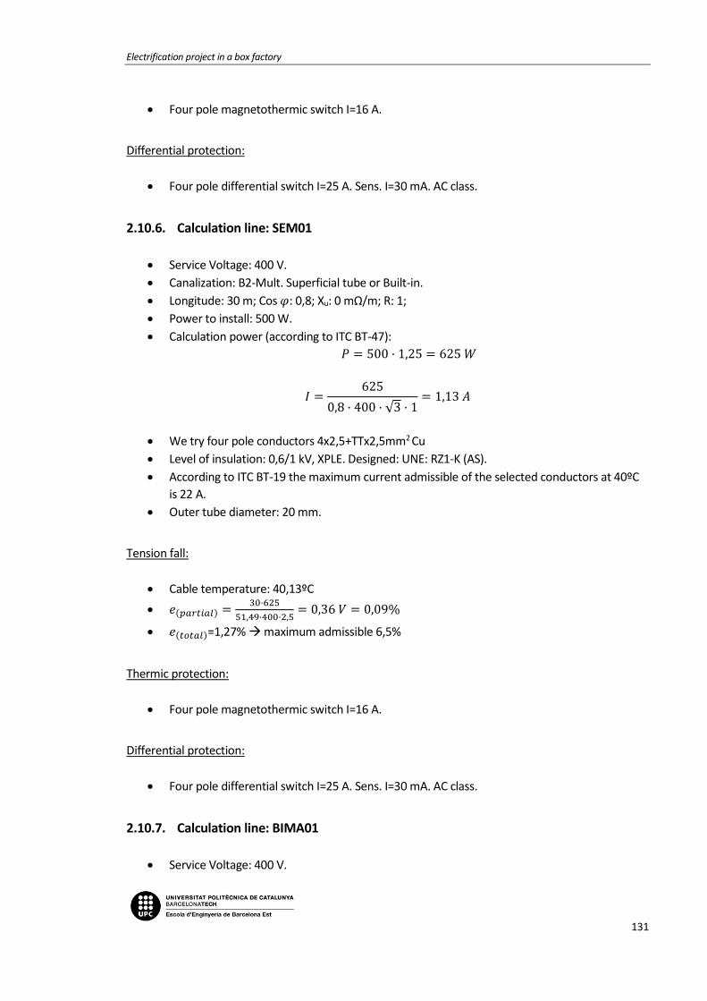
Electrification project in a box factory
131
Four pole magnetothermic switch I=16 A.
Differential protection:
Four pole differential switch I=25 A. Sens. I=30 mA. AC class.
2.10.6. Calculation line: SEM01
Service Voltage: 400 V.
Canalization: B2-Mult. Superficial tube or Built-in.
Longitude: 30 m; Cos 𝜑: 0,8; Xu: 0 mΩ/m; R: 1;
Power to install: 500 W.
Calculation power (according to ITC BT-47):
𝑃 = 500 · 1,25 = 625 𝑊
𝐼 =625
0,8 · 400 · √3 · 1= 1,13 𝐴
We try four pole conductors 4x2,5+TTx2,5mm2 Cu
Level of insulation: 0,6/1 kV, XPLE. Designed: UNE: RZ1-K (AS).
According to ITC BT-19 the maximum current admissible of the selected conductors at 40ºC
is 22 A.
Outer tube diameter: 20 mm.
Tension fall:
Cable temperature: 40,13ºC
𝑒(𝑝𝑎𝑟𝑡𝑖𝑎𝑙) =30·625
51,49·400·2,5= 0,36 𝑉 = 0,09%
𝑒(𝑡𝑜𝑡𝑎𝑙)=1,27% maximum admissible 6,5%
Thermic protection:
Four pole magnetothermic switch I=16 A.
Differential protection:
Four pole differential switch I=25 A. Sens. I=30 mA. AC class.
2.10.7. Calculation line: BIMA01
Service Voltage: 400 V.

Memoria
132
Canalization: B2-Mult. Superficial tube or Built-in.
Longitude: 40 m; Cos 𝜑: 0,8; Xu: 0 mΩ/m; R: 1;
Power to install: 5.250 W.
Calculation power (according to ITC BT-47):
𝑃 = 5.250 · 1,25 = 6.562,5 𝑊
𝐼 =6.562,5
0,8 · 400 · √3 · 1= 11,84 𝐴
We try four pole conductors 4x2,5+TTx2,5mm2 Cu
Level of insulation: 0,6/1 kV, XPLE. Designed: UNE: RZ1-K (AS).
According to ITC BT-19 the maximum current admissible of the selected conductors at 40ºC
is 22 A.
Outer tube diameter: 20 mm.
Tension fall:
Cable temperature: 54,48ºC
𝑒(𝑝𝑎𝑟𝑡𝑖𝑎𝑙) =40·6.562,5
48,94·400·2,5= 5,36 𝑉 = 1,34%
𝑒(𝑡𝑜𝑡𝑎𝑙)=2,52% maximum admissible 6,5%
Thermic protection:
Four pole magnetothermic switch I=16 A.
Differential protection:
Four pole differential switch I=25 A. Sens. I=30 mA. AC class.
2.10.8. Calculation line: PAMA01
Service Voltage: 400 V.
Canalization: B2-Mult. Superficial tube or Built-in.
Longitude: 30 m; Cos 𝜑: 0,8; Xu: 0 mΩ/m; R: 1;
Power to install: 2.944 W.
Calculation power (according to ITC BT-47):
𝑃 = 2.944 · 1,25 = 3.680 𝑊
𝐼 =3.680
0,8 · 400 · √3 · 1= 6,64 𝐴
We try four pole conductors 4x2,5+TTx2,5mm2 Cu

Electrification project in a box factory
133
Level of insulation: 0,6/1 kV, XPLE. Designed: UNE: RZ1-K (AS).
According to ITC BT-19 the maximum current admissible of the selected conductors at 40ºC
is 22 A.
Outer tube diameter: 20 mm.
Tension fall:
Cable temperature: 44,55ºC
𝑒(𝑝𝑎𝑟𝑡𝑖𝑎𝑙) =30·3.680
50,68·400·2,5= 2,18 𝑉 = 0,54%
𝑒(𝑡𝑜𝑡𝑎𝑙)=1,72% maximum admissible 6,5%
Thermic protection:
Four pole magnetothermic switch I=16 A.
Differential protection:
Four pole differential switch I=25 A. Sens. I=30 mA. AC class.
2.10.9. Calculation line: EBR01
Service Voltage: 400 V.
Canalization: B2-Mult. Superficial tube or Built-in.
Longitude: 25 m; Cos 𝜑: 0,8; Xu: 0 mΩ/m; R: 1;
Power to install: 1.200 W.
Calculation power (according to ITC BT-47):
𝑃 = 600 · 1,25 + 600 = 1.350 𝑊
𝐼 =1.350
0,8 · 400 · √3 · 1= 2,44 𝐴
We try four pole conductors 4x2,5+TTx2,5mm2 Cu
Level of insulation: 0,6/1 kV, XPLE. Designed: UNE: RZ1-K (AS).
According to ITC BT-19 the maximum current admissible of the selected conductors at 40ºC
is 22 A.
Outer tube diameter: 20 mm.
Tension fall:
Cable temperature: 40,61ºC
𝑒(𝑝𝑎𝑟𝑡𝑖𝑎𝑙) =25·1.350
51,4·400·2,5= 0,66 𝑉 = 0,16%

Memoria
134
𝑒(𝑡𝑜𝑡𝑎𝑙)=1,34% maximum admissible 6,5%
Thermic protection:
Four pole magnetothermic switch I=16 A.
Differential protection:
Four pole differential switch I=25 A. Sens. I=30 mA. AC class.
2.10.10. Calculation line: ROLL01
Service Voltage: 400 V.
Canalization: B2-Mult. Superficial tube or Built-in.
Longitude: 15 m; Cos 𝜑: 0,8; Xu: 0 mΩ/m; R: 1;
Power to install: 5.150 W.
Calculation power (according to ITC BT-47):
𝑃 = 1.100 · 1,25 + 4.050 = 5.425 𝑊
𝐼 =5.425
0,8 · 400 · √3 · 1= 9,79 𝐴
We try four pole conductors 4x2,5+TTx2,5mm2 Cu
Level of insulation: 0,6/1 kV, XPLE. Designed: UNE: RZ1-K (AS).
According to ITC BT-19 the maximum current admissible of the selected conductors at 40ºC
is 22 A.
Outer tube diameter: 20 mm.
Tension fall:
Cable temperature: 49,9ºC
𝑒(𝑝𝑎𝑟𝑡𝑖𝑎𝑙) =15·5.425
49,73·400·2,5= 1,64 𝑉 = 0,41%
𝑒(𝑡𝑜𝑡𝑎𝑙)=1,59% maximum admissible 6,5%
Thermic protection:
Four pole magnetothermic switch I=16 A.
Differential protection:
Four pole differential switch I=25 A. Sens. I=30 mA. AC class.
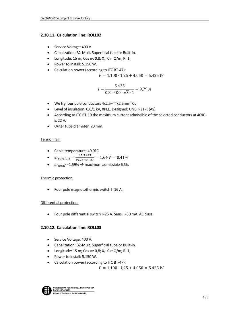
Electrification project in a box factory
135
2.10.11. Calculation line: ROLL02
Service Voltage: 400 V.
Canalization: B2-Mult. Superficial tube or Built-in.
Longitude: 15 m; Cos 𝜑: 0,8; Xu: 0 mΩ/m; R: 1;
Power to install: 5.150 W.
Calculation power (according to ITC BT-47):
𝑃 = 1.100 · 1,25 + 4.050 = 5.425 𝑊
𝐼 =5.425
0,8 · 400 · √3 · 1= 9,79 𝐴
We try four pole conductors 4x2,5+TTx2,5mm2 Cu
Level of insulation: 0,6/1 kV, XPLE. Designed: UNE: RZ1-K (AS).
According to ITC BT-19 the maximum current admissible of the selected conductors at 40ºC
is 22 A.
Outer tube diameter: 20 mm.
Tension fall:
Cable temperature: 49,9ºC
𝑒(𝑝𝑎𝑟𝑡𝑖𝑎𝑙) =15·5.425
49,73·400·2,5= 1,64 𝑉 = 0,41%
𝑒(𝑡𝑜𝑡𝑎𝑙)=1,59% maximum admissible 6,5%
Thermic protection:
Four pole magnetothermic switch I=16 A.
Differential protection:
Four pole differential switch I=25 A. Sens. I=30 mA. AC class.
2.10.12. Calculation line: ROLL03
Service Voltage: 400 V.
Canalization: B2-Mult. Superficial tube or Built-in.
Longitude: 15 m; Cos 𝜑: 0,8; Xu: 0 mΩ/m; R: 1;
Power to install: 5.150 W.
Calculation power (according to ITC BT-47):
𝑃 = 1.100 · 1,25 + 4.050 = 5.425 𝑊

Memoria
136
𝐼 =5.425
0,8 · 400 · √3 · 1= 9,79 𝐴
We try four pole conductors 4x2,5+TTx2,5mm2 Cu
Level of insulation: 0,6/1 kV, XPLE. Designed: UNE: RZ1-K (AS).
According to ITC BT-19 the maximum current admissible of the selected conductors at 40ºC
is 22 A.
Outer tube diameter: 20 mm.
Tension fall:
Cable temperature: 49,9ºC
𝑒(𝑝𝑎𝑟𝑡𝑖𝑎𝑙) =15·5.425
49,73·400·2,5= 1,64 𝑉 = 0,41%
𝑒(𝑡𝑜𝑡𝑎𝑙)=1,59% maximum admissible 6,5%
Thermic protection:
Four pole magnetothermic switch I=16 A.
Differential protection:
Four pole differential switch I=25 A. Sens. I=30 mA. AC class.
2.10.13. Calculation line: TRIFASIC PLUGS
Service Voltage: 400 V.
Canalization: B2-Mult. Superficial tube or Built-in.
Longitude: 30 m; Cos 𝜑: 0,8; Xu: 0 mΩ/m; R: 1;
Power to install: 2.500 W.
Calculation power: 𝑃 = 2.500 𝑊
𝐼 =2.500
0,8 · 400 · √3 · 1= 4,51 𝐴
We try four pole conductors 4x10+TTx10mm2 Cu
Level of insulation: 0,6/1 V, XPLE. Designed: UNE: RZ1-K (AS).
According to ITC BT-19 the maximum current admissible of the selected conductors at 40ºC
is 52 A.
Outer tube diameter: 32 mm.
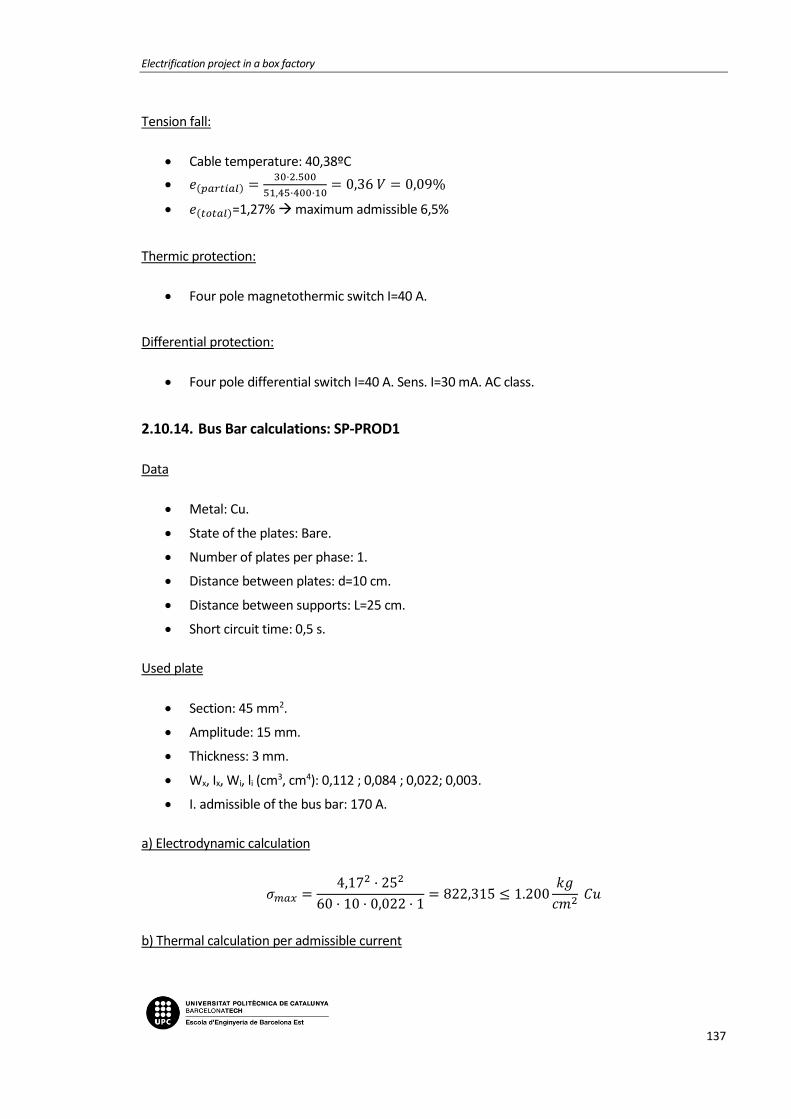
Electrification project in a box factory
137
Tension fall:
Cable temperature: 40,38ºC
𝑒(𝑝𝑎𝑟𝑡𝑖𝑎𝑙) =30·2.500
51,45·400·10= 0,36 𝑉 = 0,09%
𝑒(𝑡𝑜𝑡𝑎𝑙)=1,27% maximum admissible 6,5%
Thermic protection:
Four pole magnetothermic switch I=40 A.
Differential protection:
Four pole differential switch I=40 A. Sens. I=30 mA. AC class.
2.10.14. Bus Bar calculations: SP-PROD1
Data
Metal: Cu.
State of the plates: Bare.
Number of plates per phase: 1.
Distance between plates: d=10 cm.
Distance between supports: L=25 cm.
Short circuit time: 0,5 s.
Used plate
Section: 45 mm2.
Amplitude: 15 mm.
Thickness: 3 mm.
Wx, Ix, Wi, li (cm3, cm4): 0,112 ; 0,084 ; 0,022; 0,003.
I. admissible of the bus bar: 170 A.
a) Electrodynamic calculation
𝜎𝑚𝑎𝑥 =4,17
2 · 252
60 · 10 · 0,022 · 1= 822,315 ≤ 1.200
𝑘𝑔
𝑐𝑚2 𝐶𝑢
b) Thermal calculation per admissible current

Memoria
138
𝐼𝑐𝑎𝑙 = 55,79 𝐴
𝐼𝑎𝑑𝑚 = 170 𝐴
c) Check for thermal request in short circuit
𝐼𝑝𝑐𝑐 = 4,17 𝑘𝐴
𝐼𝑐𝑐𝑐𝑠 =𝐾𝑐 · 𝑆
1000 · √𝑡𝑐𝑐
=164 · 45
1000 · √0,5= 10,44 𝑘𝐴
2.11. Sub-panel SP-WORKSHOP
2.11.1. Power demand
-Total installed power:
LT01 1.104 W
PLUGS 650 W
EMERGENCY 50 W
SERVICEBOX01 3.000 W
SERVICEBOX02 3.000 W
SERVICEBOX03 3.000 W
AER01 160 W
2.11.2. Calculation line: LT1
Service Voltage: 230 V.
Canalization: C-Unip. or Mult. on wall.
Longitude: 0,3 m; Cos 𝜑: 0,8; Xu: 0 mΩ/m;
Power to install: 1.804 W.
Simultaneity factor: 0,5.
Calculation power (according to ITC BT-44):
𝑃 = 1.210 𝑊
𝐼 =1.210
230 · 0,8= 6,58𝐴

Electrification project in a box factory
139
We try unipolar conductors 2x4mm2 Cu
Level of insulation: 0,6/1 V, XPLE. Designed: UNE: RZ1-K (AS).
According to ITC BT-19 the maximum current admissible of the selected conductors at 40ºC
is 31 A.
Tension fall:
Cable temperature: 41,35ºC
𝑒(𝑝𝑎𝑟𝑡𝑖𝑎𝑙) =2·0,3·1.210
51,27·230·4= 0,02𝑉 = 0,01%
𝑒(𝑡𝑜𝑡𝑎𝑙)=0,84% maximum admissible 4,5%
Differential protection:
Two pole differential switch I=40 A. Sens. I=30 mA. AC class.
2.11.3. Calculation line: LT01
Service Voltage: 230 V.
Canalization: B1-Unip. tube superf. or built-in.
Longitude: 20 m; Cos 𝜑: 1; Xu: 0 mΩ/m;
Power to install: 1.104 W.
Calculation power (according to ITC BT-44):
𝑃 = 720 · 1,8 + 384 = 1.680 𝑊
𝐼 =1.680
230 · 1= 7,3 𝐴
We try unipolar conductors 2x1,5+TTx1,5mm2 Cu
Level of insulation: 0,6/1 V, XPLE. Designed: UNE: RZ1-K (AS).
According to ITC BT-19 the maximum current admissible of the selected conductors at 40ºC
is 15 A.
Outer tube diameter: 16 mm.
Tension fall:
Cable temperature: 47,11ºC
𝑒(𝑝𝑎𝑟𝑡𝑖𝑎𝑙) =2·20·1.680
50,22·230·1,5= 3,88𝑉 = 1,69%
𝑒(𝑡𝑜𝑡𝑎𝑙)=2,52% maximum admissible 4,5%
Thermic protection:

Memoria
140
Two pole magnetothermic switch I=10 A.
2.11.4. Calculation line: PLUGS
Service Voltage: 230 V.
Canalization: B1-Unip. Superficial tube or Built-in.
Longitude: 20 m; Cos 𝜑: 0,8; Xu: 0 mΩ/m;
Power to install: 650 W.
Calculation power: 650 W
𝐼 =650
0,8 · 230= 3,53 𝐴
We try unipolar conductors 2x1,5+TTX1,5mm2 Cu
Level of insulation: 450/700 V, XPLE. Designed: UNE: RZ1-K (AS).
According to ITC BT-19 the maximum current admissible of the selected conductors at 40ºC
is 15A.
Outer tube diameter: 16 mm.
Tension fall:
Cable temperature: 41,66ºC
𝑒(𝑝𝑎𝑟𝑡𝑖𝑎𝑙) =2·20·650
51,21·230·1,5= 1,47 𝑉 = 0,64%
𝑒(𝑡𝑜𝑡𝑎𝑙)=1,48% maximum admissible 6,5%
Thermic protection:
Two pole magnetothermic switch I=16 A
2.11.5. Calculation line: EMERGENCY
Service Voltage: 230 V.
Canalization: B1-Unip. tube superf. or Built-in.
Longitude: 20 m; Cos 𝜑: 1; Xu: 0 mΩ/m;
Power to install: 50 W.
Calculation power (according to ITC BT-44):
𝑃 = 50 · 1,8 = 90 𝑊
𝐼 =90
230= 0,39 𝐴

Electrification project in a box factory
141
We try unipolar conductors 2x1,5+TTx1,5mm2 Cu
Level of insulation: 0,6/1 V, XPLE. Designed: UNE: RZ1-K (AS).
According to ITC BT-19 the maximum current admissible of the selected conductors at 40ºC
is 15 A.
Outer tube diameter: 16 mm.
Tension fall:
Cable temperature: 40,02ºC
𝑒(𝑝𝑎𝑟𝑡𝑖𝑎𝑙) =2·20·90
51,51·230·1,5= 0,2𝑉 = 0,09%
𝑒(𝑡𝑜𝑡𝑎𝑙)=0,92% maximum admissible 4,5%
Thermic protection:
Two pole magnetothermic switch I=10 A.
2.11.6. Calculation line: SERVICEBOX01
Service Voltage: 400 V.
Canalization: B1-Unip. Superficial tube or Built-in.
Longitude: 15 m; Cos 𝜑: 0,8; Xu: 0 mΩ/m;
Power to install: 3.000 W.
Calculation power: 3.000 W
𝐼 =3.000
0,8 · 400 · √3= 5,41 𝐴
We try unipolar conductors 4x10+TTx10mm2 Cu
Level of insulation: 0,6/1 V, XPLE. Designed: UNE: RZ1-K (AS).
According to ITC BT-19 the maximum current admissible of the selected conductors at 40ºC
is 44A.
Outer tube diameter: 32 mm.
Tension fall:
Cable temperature: 40,45ºC
𝑒(𝑝𝑎𝑟𝑡𝑖𝑎𝑙) =15·3.000
51,43·400·10= 0,22 𝑉 = 0,05%
𝑒(𝑡𝑜𝑡𝑎𝑙)=0,88% maximum admissible 6,5%
Thermic protection:
Memoria
142
Four pole magnetothermic switch I=40 A.
Differential protection:
Four pole differential switch I=40 A. Sens. I=30 mA. AC class.
2.11.7. Calculation line: SERVICEBOX02
Service Voltage: 400 V.
Canalization: B1-Unip. Superficial tube or Built-in.
Longitude: 20 m; Cos 𝜑: 0,8; Xu: 0 mΩ/m;
Power to install: 3.000 W.
Calculation power: 3.000 W
𝐼 =3.000
0,8 · 400 · √3= 5,41 𝐴
We try unipolar conductors 4x10+TTx10mm2 Cu
Level of insulation: 0,6/1 V, XPLE. Designed: UNE: RZ1-K (AS).
According to ITC BT-19 the maximum current admissible of the selected conductors at 40ºC
is 44A.
Outer tube diameter: 32 mm.
Tension fall:
Cable temperature: 40,45ºC
𝑒(𝑝𝑎𝑟𝑡𝑖𝑎𝑙) =20·3.000
51,43·400·10= 0,29 𝑉 = 0,07%
𝑒(𝑡𝑜𝑡𝑎𝑙)=0,9% maximum admissible 6,5%
Thermic protection:
Four pole magnetothermic switch I=40 A.
Differential protection:
Four pole differential switch I=40 A. Sens. I=30 mA. AC class.
2.11.8. Calculation line: SERVICE BOXES
Service Voltage: 400 V.
Canalization: B1-Unip. Superficial tube or Built-in.

Electrification project in a box factory
143
Longitude: 25 m; Cos 𝜑: 0,8; Xu: 0 mΩ/m;
Power to install: 3.000 W.
Calculation power: 3.000 W
𝐼 =3.000
0,8 · 400 · √3= 5,41 𝐴
We try unipolar conductors 4x10+TTx10mm2 Cu
Level of insulation: 0,6/1 V, XPLE. Designed: UNE: RZ1-K (AS).
According to ITC BT-19 the maximum current admissible of the selected conductors at 40ºC
is 44A.
Outer tube diameter: 32 mm.
Tension fall:
Cable temperature: 40,45ºC
𝑒(𝑝𝑎𝑟𝑡𝑖𝑎𝑙) =25·3.000
51,43·400·10= 0,36 𝑉 = 0,09%
𝑒(𝑡𝑜𝑡𝑎𝑙)=0,92% maximum admissible 6,5%
Thermic protection:
Four pole magnetothermic switch I=40 A.
Differential protection:
Four pole differential switch I=40 A. Sens. I=30 mA. AC class.
2.11.9. Calculation line: AER01
Service Voltage: 400 V.
Canalization: B1-Unip. Superficial tube or Built-in.
Longitude: 15 m; Cos 𝜑: 0,8; Xu: 0 mΩ/m;R:1;
Power to install: 160 W.
Calculation power (According to ITC BT-47):
𝑃 = 80 · 1,25 + 80 = 180 W
𝐼 =180
0,8 · 400 · √3= 0,32 𝐴
We try unipolar conductors 4x2,5+TTx2,5mm2 Cu
Memoria
144
Level of insulation: 0,6/1 V, XPLE. Designed: UNE: RZ1-K (AS).
According to ITC BT-19 the maximum current admissible of the selected conductors at 40ºC
is 18,5A.
Outer tube diameter: 20 mm.
Tension fall:
Cable temperature: 40,01ºC
𝑒(𝑝𝑎𝑟𝑡𝑖𝑎𝑙) =15·180
51,51·400·2,5= 0,05 𝑉 = 0,01%
𝑒(𝑡𝑜𝑡𝑎𝑙)=0,84% maximum admissible 6,5%
Thermic protection:
Four pole magnetothermic switch I=6 A.
Differential protection:
Four pole differential switch I=25 A. Sens. I=30 mA. AC class.
2.11.10. Bus Bar calculations: SP-WORKSHOP
Data
Metal: Cu.
State of the plates: Bare.
Number of plates per phase: 1.
Distance between plates: d=10 cm.
Distance between supports: L=25 cm.
Short circuit time: 0,5 s.
Used plate
Section: 24 mm2.
Amplitude: 12 mm.
Thickness: 2 mm.
Wx, Ix, Wi, li (cm3, cm4): 0,048 ; 0,0288 ; 0,008; 0,0008.
I. admissible of the bus bar: 110 A.
a) Electrodynamic calculation
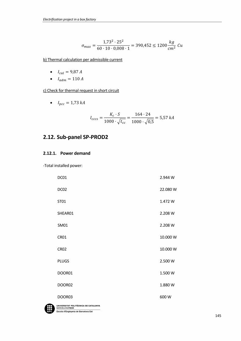
Electrification project in a box factory
145
𝜎𝑚𝑎𝑥 =1,73
2 · 252
60 · 10 · 0,008 · 1= 390,452 ≤ 1200
𝑘𝑔
𝑐𝑚2 𝐶𝑢
b) Thermal calculation per admissible current
𝐼𝑐𝑎𝑙 = 9,87 𝐴
𝐼𝑎𝑑𝑚 = 110 𝐴
c) Check for thermal request in short circuit
𝐼𝑝𝑐𝑐 = 1,73 𝑘𝐴
𝐼𝑐𝑐𝑐𝑠 =𝐾𝑐 · 𝑆
1000 · √𝑡𝑐𝑐
=164 · 24
1000 · √0,5= 5,57 𝑘𝐴
2.12. Sub-panel SP-PROD2
2.12.1. Power demand
-Total installed power:
DC01 2.944 W
DC02 22.080 W
ST01 1.472 W
SHEAR01 2.208 W
SM01 2.208 W
CR01 10.000 W
CR02 10.000 W
PLUGS 2.500 W
DOOR01 1.500 W
DOOR02 1.880 W
DOOR03 600 W

Memoria
146
2.12.2. Calculation line: DC01
Service Voltage: 400 V.
Canalization: B1-Unip. Superficial tube or Built-in.
Longitude: 25 m; Cos 𝜑: 0,8; Xu: 0 mΩ/m;R:1;
Power to install: 2.944 W.
Calculation power (According to ITC BT-47):
𝑃 = 2.944 · 1,25 = 3.680 W
𝐼 =3.680
0,8 · 400 · √3= 6,64 𝐴
We try unipolar conductors 4x2,5+TTx2,5mm2 Cu
Level of insulation: 0,6/1 V, XPLE. Designed: UNE: RZ1-K (AS).
According to ITC BT-19 the maximum current admissible of the selected conductors at 40ºC
is 18,5A.
Outer tube diameter: 20 mm.
Tension fall:
Cable temperature: 43,68ºC
𝑒(𝑝𝑎𝑟𝑡𝑖𝑎𝑙) =25·3.680
50,8·400·2,5= 1,81 𝑉 = 0,45%
𝑒(𝑡𝑜𝑡𝑎𝑙)=1,71% maximum admissible 6,5%
Thermic protection:
Four pole magnetothermic switch I=16 A.
Differential protection:
Four pole differential switch I=25 A. Sens. I=30 mA. AC class.
2.12.3. Calculation line: DC02
Service Voltage: 400 V.
Canalization: B2-Mult. Superficial tube or Built-in.
Longitude: 50 m; Cos 𝜑: 0,8; Xu: 0 mΩ/m; R: 1;
Power to install: 22.080 W.
Calculation power (according to ITC BT-47):
𝑃 = 22.080 · 1,25 = 27.600 𝑊
Electrification project in a box factory
147
𝐼 =27.600
0,8 · 400 · √3 · 1= 49,8 𝐴
We try four pole conductors 4x25+TTx16mm2 Cu
Level of insulation: 0,6/1 kV, XPLE. Designed: UNE: RZ1-K (AS).
According to ITC BT-19 the maximum current admissible of the selected conductors at 40ºC
is 88A.
Outer tube diameter: 50 mm.
Tension fall:
Cable temperature: 56,01ºC
𝑒(𝑝𝑎𝑟𝑡𝑖𝑎𝑙) =50·27.600
48,68·400·25= 2,83 𝑉 = 0,71%
𝑒(𝑡𝑜𝑡𝑎𝑙)=1,96% maximum admissible 6,5%
Thermic protection:
Four pole magnetothermic switch I=50 A.
Differential protection:
Four pole differential switch I=63 A. Sens. I=30 mA. AC class.
2.12.4. Calculation line: ST01
Service Voltage: 400 V.
Canalization: B1-Unip. Superficial tube or Built-in.
Longitude: 35 m; Cos 𝜑: 0,8; Xu: 0 mΩ/m;R:1;
Power to install: 1.472 W.
Calculation power (According to ITC BT-47):
𝑃 = 1.472 · 1,25 = 1.840 W
𝐼 =1.840
0,8 · 400 · √3= 3,32 𝐴
We try unipolar conductors 4x2,5+TTx2,5mm2 Cu
Level of insulation: 0,6/1 V, XPLE. Designed: UNE: RZ1-K (AS).
According to ITC BT-19 the maximum current admissible of the selected conductors at 40ºC
is 18,5A.
Outer tube diameter: 20 mm.
Memoria
148
Tension fall:
Cable temperature: 40,97ºC
𝑒(𝑝𝑎𝑟𝑡𝑖𝑎𝑙) =35·1.840
51,34·400·2,5= 1,25 𝑉 = 0,31%
𝑒(𝑡𝑜𝑡𝑎𝑙)=1,57% maximum admissible 6,5%
Thermic protection:
Four pole magnetothermic switch I=16 A.
Differential protection:
Four pole differential switch I=25 A. Sens. I=30 mA. AC class.
2.12.5. Calculation line: SHEAR01
Service Voltage: 230 V.
Canalization: B1-Unip. tube superf. or built-in.
Longitude: 30 m; Cos 𝜑: 0,8; Xu: 0 mΩ/m;
Power to install: 2.208 W.
Calculation power (according to ITC BT-47):
𝑃 = 2.208 · 1,25 = 2.760 𝑊
𝐼 =2.760
230 · 0,8= 15 𝐴
We try unipolar conductors 2x2,5+TTx2,5mm2 Cu
Level of insulation: 0,6/1 V, XPLE. Designed: UNE: RZ1-K (AS).
According to ITC BT-19 the maximum current admissible of the selected conductors at 40ºC
is 21 A.
Outer tube diameter: 20 mm.
Tension fall:
Cable temperature: 55,31ºC
𝑒(𝑝𝑎𝑟𝑡𝑖𝑎𝑙) =2·30·2.760
48,8·230·2,5= 5,9 𝑉 = 2,57%
𝑒(𝑡𝑜𝑡𝑎𝑙)=3,82% maximum admissible 6,5%
Thermic protection:
Two pole magnetothermic switch I=16 A.

Electrification project in a box factory
149
Differential protection:
Four pole differential switch I=25 A. Sens. I=300 mA. AC class.
2.12.6. Calculation line: SM01
Service Voltage: 230 V.
Canalization: B1-Unip. tube superf. or built-in.
Longitude: 30 m; Cos 𝜑: 0,8; Xu: 0 mΩ/m;
Power to install: 2.208 W.
Calculation power (according to ITC BT-47):
𝑃 = 736 · 1,25 + 1.472 = 2.392 𝑊
𝐼 =2.392
230 · 0,8= 13 𝐴
We try unipolar conductors 2x2,5+TTx2,5mm2 Cu
Level of insulation: 0,6/1 V, XPLE. Designed: UNE: RZ1-K (AS).
According to ITC BT-19 the maximum current admissible of the selected conductors at 40ºC
is 21 A.
Outer tube diameter: 20 mm.
Tension fall:
Cable temperature: 51,5ºC
𝑒(𝑝𝑎𝑟𝑡𝑖𝑎𝑙) =2·30·2.392
49,45·230·2,5= 5,05 𝑉 = 2,19%
𝑒(𝑡𝑜𝑡𝑎𝑙)=3,45% maximum admissible 6,5%
Thermic protection:
Two pole magnetothermic switch I=16 A.
Differential protection:
Four pole differential switch I=25 A. Sens. I=300 mA. AC class.
2.12.7. Calculation line: CR01
Service Voltage: 400 V.
Canalization: B1-Unip. Superficial tube or Built-in.
Longitude: 35 m; Cos 𝜑: 0,8; Xu: 0 mΩ/m;R:1;
Power to install: 10.000 W.
Memoria
150
Calculation power (According to ITC BT-47):
𝑃 = 10.000 · 1,25 = 12.500 W
𝐼 =12.500
0,8 · 400 · √3= 22,55 𝐴
We try unipolar conductors 4x6+TTx6mm2 Cu
Level of insulation: 0,6/1 V, XPLE. Designed: UNE: RZ1-K (AS).
According to ITC BT-19 the maximum current admissible of the selected conductors at 40ºC
is 32A.
Outer tube diameter: 25 mm.
Tension fall:
Cable temperature: 54,9ºC
𝑒(𝑝𝑎𝑟𝑡𝑖𝑎𝑙) =35·12.500
48,87·400·6= 3,73 𝑉 = 0,93%
𝑒(𝑡𝑜𝑡𝑎𝑙)=2,19% maximum admissible 6,5%
Thermic protection:
Four pole magnetothermic switch I=32 A.
Differential protection:
Four pole differential switch I=40 A. Sens. I=30 mA. AC class.
2.12.8. Calculation line: CR02
Service Voltage: 400 V.
Canalization: B1-Unip. Superficial tube or Built-in.
Longitude: 25 m; Cos 𝜑: 0,8; Xu: 0 mΩ/m;R:1;
Power to install: 10.000 W.
Calculation power (According to ITC BT-47):
𝑃 = 10.000 · 1,25 = 12.500 W
𝐼 =12.500
0,8 · 400 · √3= 22,55 𝐴
We try unipolar conductors 4x6+TTx6mm2 Cu
Electrification project in a box factory
151
Level of insulation: 0,6/1 V, XPLE. Designed: UNE: RZ1-K (AS).
According to ITC BT-19 the maximum current admissible of the selected conductors at 40ºC
is 32A.
Outer tube diameter: 25 mm.
Tension fall:
Cable temperature: 54,9ºC
𝑒(𝑝𝑎𝑟𝑡𝑖𝑎𝑙) =25·12.500
48,87·400·6= 2,66 𝑉 = 0,67%
𝑒(𝑡𝑜𝑡𝑎𝑙)=1,92% maximum admissible 6,5%
Thermic protection:
Four pole magnetothermic switch I=32 A.
Differential protection:
Four pole differential switch I=40 A. Sens. I=30 mA. AC class.
2.12.9. Calculation line: PLUGS
Service Voltage: 230 V.
Canalization: B1-Unip. Superficial tube or Built-in.
Longitude: 25 m; Cos 𝜑: 0,8; Xu: 0 mΩ/m;
Power to install: 2.500 W.
Calculation power: 2.500 W
𝐼 =2.500
0,8 · 230= 13,59 𝐴
We try unipolar conductors 2x2,5+TTX2,5mm2 Cu
Level of insulation: 450/700 V, XPLE. Designed: UNE: RZ1-K (AS).
According to ITC BT-19 the maximum current admissible of the selected conductors at 40ºC
is 21A.
Outer tube diameter: 20 mm.
Tension fall:
Cable temperature: 52,56ºC
𝑒(𝑝𝑎𝑟𝑡𝑖𝑎𝑙) =2·25·2.500
49,27·230·2,5= 4,41 𝑉 = 1,92%
𝑒(𝑡𝑜𝑡𝑎𝑙)=3,17% maximum admissible 6,5%

Memoria
152
Thermic protection:
Two pole magnetothermic switch I=16 A
Differential protection:
Four pole differential switch I=25 A. Sens. I=30 mA. AC class.
2.12.10. Calculation line: PROD2-1
Service Voltage: 400 V.
Canalization: C-Unip. or Mult. on wall.
Longitude: 0,3 m; Cos 𝜑: 0,8; Xu: 0 mΩ/m;
Power to install: 3.380 W.
Simultaneity factor: 1
Calculation power (according to ITC BT-47):
𝑃 = 1.880 · 1,25 + 1.500 = 3.850 𝑊
𝐼 =3.850
0,8 · 400 · √3= 6,95 𝐴
We try unipolar conductors 4x6mm2 Cu
Level of insulation: 0,6/1 V, XPLE. Designed: UNE: RZ1-K (AS).
According to ITC BT-19 the maximum current admissible of the selected conductors at 40ºC
is 36A.
Tension fall:
Cable temperature: 41,12ºC
𝑒(𝑝𝑎𝑟𝑡𝑖𝑎𝑙) =0,3·3.850
51,31·400·6= 0,01 𝑉 = 0%
𝑒(𝑡𝑜𝑡𝑎𝑙)=1,26% maximum admissible 4,5%
Differential protection:
Four pole differential switch I=40 A. Sens. I=30 mA. AC class.
2.12.11. Calculation line: DOOR01
Service Voltage: 400 V.
Canalization: B1-Unip. Superficial tube or Built-in.
Longitude: 46 m; Cos 𝜑: 0,8; Xu: 0 mΩ/m;R:1;

Electrification project in a box factory
153
Power to install: 1.500 W.
Calculation power (According to ITC BT-47):
𝑃 = 1.500 · 1,25 = 1.875 W
𝐼 =1.875
0,8 · 400 · √3= 3,38 𝐴
We try unipolar conductors 4x2,5+TTx2,5mm2 Cu
Level of insulation: 0,6/1 V, XPLE. Designed: UNE: RZ1-K (AS).
According to ITC BT-19 the maximum current admissible of the selected conductors at 40ºC
is 18,5A.
Outer tube diameter: 20 mm.
Tension fall:
Cable temperature: 41ºC
𝑒(𝑝𝑎𝑟𝑡𝑖𝑎𝑙) =46·1.875
51,33·400·2,5= 1,68 𝑉 = 0,42%
𝑒(𝑡𝑜𝑡𝑎𝑙)=1,68% maximum admissible 6,5%
Thermic protection:
Four pole magnetothermic switch I=16 A.
2.12.12. Calculation line: DOOR02
Service Voltage: 400 V.
Canalization: B1-Unip. Superficial tube or Built-in.
Longitude: 60 m; Cos 𝜑: 0,8; Xu: 0 mΩ/m;R:1;
Power to install: 1.880 W.
Calculation power (According to ITC BT-47):
𝑃 = 1.880 · 1,25 = 2.350 W
𝐼 =2.350
0,8 · 400 · √3= 4,24 𝐴
We try unipolar conductors 4x2,5+TTx2,5mm2 Cu
Level of insulation: 0,6/1 V, XPLE. Designed: UNE: RZ1-K (AS).
According to ITC BT-19 the maximum current admissible of the selected conductors at 40ºC
is 18,5A.

Memoria
154
Outer tube diameter: 20 mm.
Tension fall:
Cable temperature: 41,58ºC
𝑒(𝑝𝑎𝑟𝑡𝑖𝑎𝑙) =60·2.350
51,22·400·2,5= 2,75 𝑉 = 0,69%
𝑒(𝑡𝑜𝑡𝑎𝑙)=1,94% maximum admissible 6,5%
Thermic protection:
Four pole magnetothermic switch I=16 A.
2.12.13. Calculation line: DOOR03
Service Voltage: 230 V.
Canalization: B1-Unip. Superficial tube or Built-in.
Longitude: 50 m; Cos 𝜑: 0,8; Xu: 0 mΩ/m;R:1;
Power to install: 600 W.
Calculation power (According to ITC BT-47):
𝑃 = 600 · 1,25 = 750 W
𝐼 =750
0,8 · 230= 4,08 𝐴
We try unipolar conductors 2x2,5+TTx2,5mm2 Cu
Level of insulation: 0,6/1 V, XPLE. Designed: UNE: RZ1-K (AS).
According to ITC BT-19 the maximum current admissible of the selected conductors at 40ºC
is 21 A.
Outer tube diameter: 20 mm.
Tension fall:
Cable temperature: 41,13ºC
𝑒(𝑝𝑎𝑟𝑡𝑖𝑎𝑙) =2·50·750
51,31·230·2,5= 2,54 𝑉 = 1,11%
𝑒(𝑡𝑜𝑡𝑎𝑙)=2,36% maximum admissible 6,5%
Thermic protection:
Four pole magnetothermic switch I=16 A.

Electrification project in a box factory
155
Differential protection:
Two pole differential switch I=25 A. Sens. I=30 mA. AC class.
2.12.14. Bus Bar calculations: SP-PROD2
Data
Metal: Cu.
State of the plates: Bare.
Number of plates per phase: 1.
Distance between plates: d=10 cm.
Distance between supports: L=25 cm.
Short circuit time: 0,5 s.
Used plate
Section: 75 mm2.
Amplitude: 25 mm.
Thickness: 3 mm.
Wx, Ix, Wi, li (cm3, cm4): 0,312 ; 0,39 ; 0,037; 0,005.
I. admissible of the bus bar: 270 A.
a) Electrodynamic calculation
𝜎𝑚𝑎𝑥 =5,9
2 · 252
60 · 10 · 0,037 · 1= 981,432 ≤ 1200
𝑘𝑔
𝑐𝑚2 𝐶𝑢
b) Thermal calculation per admissible current
𝐼𝑐𝑎𝑙 = 92,8 𝐴
𝐼𝑎𝑑𝑚 = 270 𝐴
c) Check for thermal request in short circuit
𝐼𝑝𝑐𝑐 = 5,9 𝑘𝐴
𝐼𝑐𝑐𝑐𝑠 =𝐾𝑐 · 𝑆
1000 · √𝑡𝑐𝑐
=164 · 75
1000 · √0,5= 17,39 𝑘𝐴

Memoria
156
2.13. Sub-panel SP-BOBST
2.13.1. Power demand
-Total installed power:
DC01 33.500 W
PE01 736 W
ROLLER 5.500 W
PLUGS 450 W
LT01 750 W
2.13.2. Calculation line: DC01
Service Voltage: 400 V.
Canalization: B2-Mult. Superficial tube or Built-in.
Longitude: 20 m; Cos 𝜑: 0,8; Xu: 0 mΩ/m; R: 1;
Power to install: 33.500 W.
Calculation power (according to ITC BT-47):
𝑃 = 3.500 · 1,25 + 30.000 = 34.375 𝑊
𝐼 =34.375
0,8 · 400 · √3 · 1= 62,02 𝐴
We try four pole conductors 4x25+TTx16mm2 Cu
Level of insulation: 0,6/1 kV, XPLE. Designed: UNE: RZ1-K (AS).
According to ITC BT-19 the maximum current admissible of the selected conductors at 40ºC
is 88A.
Outer tube diameter: 50 mm.
Tension fall:
Cable temperature: 64,84ºC
𝑒(𝑝𝑎𝑟𝑡𝑖𝑎𝑙) =20·34.375
47,25·400·25= 1,46 𝑉 = 0,36%
𝑒(𝑡𝑜𝑡𝑎𝑙)=1,64% maximum admissible 6,5%
Thermic protection:

Electrification project in a box factory
157
Four pole magnetothermic switch I=63 A.
Differential protection:
Four pole differential switch I=63 A. Sens. I=300 mA. AC class.
2.13.3. Calculation line: BOBST1
Service Voltage: 400 V.
Canalization: C-Unip. or Mult. on wall.
Longitude: 0,3 m; Cos 𝜑: 0,8; Xu: 0 mΩ/m;
Power to install: 6.236 W.
Simultaneity factor: 1
Calculation power (according to ITC BT-47):
𝑃 = 5.500 · 1,25 + 736 = 7.611 𝑊
𝐼 =7.611
0,8 · 400 · √3= 13,73 𝐴
We try unipolar conductors 4x6mm2 Cu
Level of insulation: 0,6/1 V, XPLE. Designed: UNE: RZ1-K (AS).
According to ITC BT-19 the maximum current admissible of the selected conductors at 40ºC
is 36A.
Tension fall:
Cable temperature: 44,37ºC
𝑒(𝑝𝑎𝑟𝑡𝑖𝑎𝑙) =0,3·7.611
50,71·400·6= 0,0 𝑉 = 0%
𝑒(𝑡𝑜𝑡𝑎𝑙)=1,28% maximum admissible 4,5%
Differential protection:
Four pole differential switch I=40 A. Sens. I=30 mA. AC class.
2.13.4. Calculation line: PE01
Service Voltage: 400 V.
Canalization: B1-Unip. Superficial tube or Built-in.
Longitude: 32 m; Cos 𝜑: 0,8; Xu: 0 mΩ/m;R:1;
Power to install: 736 W.

Memoria
158
Calculation power (According to ITC BT-47):
𝑃 = 736 · 1,25 = 920 W
𝐼 =920
0,8 · 400 · √3= 1,66 𝐴
We try unipolar conductors 4x2,5+TTx2,5mm2 Cu
Level of insulation: 0,6/1 V, XPLE. Designed: UNE: RZ1-K (AS).
According to ITC BT-19 the maximum current admissible of the selected conductors at 40ºC
is 18,5A.
Outer tube diameter: 20 mm.
Tension fall:
Cable temperature: 40,24ºC
𝑒(𝑝𝑎𝑟𝑡𝑖𝑎𝑙) =32·920
51,47·400·2,5= 0,57 𝑉 = 0,14%
𝑒(𝑡𝑜𝑡𝑎𝑙)=1,43% maximum admissible 6,5%
Thermic protection:
Four pole magnetothermic switch I=16 A.
2.13.5. Calculation line: ROLLER
Service Voltage: 400 V.
Canalization: B1-Unip. Superficial tube or Built-in.
Longitude: 25 m; Cos 𝜑: 0,8; Xu: 0 mΩ/m;R:1;
Power to install: 5.500 W.
Calculation power (According to ITC BT-47):
𝑃 = 5.500 · 1,25 = 6.875 W
𝐼 =6.875
0,8 · 400 · √3= 12,4 𝐴
We try unipolar conductors 4x2,5+TTx2,5mm2 Cu
Level of insulation: 0,6/1 V, XPLE. Designed: UNE: RZ1-K (AS).
According to ITC BT-19 the maximum current admissible of the selected conductors at 40ºC
is 18,5A.
Outer tube diameter: 20 mm.

Electrification project in a box factory
159
Tension fall:
Cable temperature: 53,49ºC
𝑒(𝑝𝑎𝑟𝑡𝑖𝑎𝑙) =25·6.875
49,11·400·2,5= 3,5 𝑉 = 0,87%
𝑒(𝑡𝑜𝑡𝑎𝑙)=2,16% maximum admissible 6,5%
Thermic protection:
Four pole magnetothermic switch I=16 A.
2.13.6. Calculation line: PLUGS
Service Voltage: 400 V.
Canalization: B1-Unip. Superficial tube or Built-in.
Longitude: 25 m; Cos 𝜑: 0,8; Xu: 0 mΩ/m;R:1;
Power to install: 450 W.
Calculation power: 𝑃 = 450 W
𝐼 =450
0,8 · 400 · √3= 0,81 𝐴
We try unipolar conductors 4x2,5+TTx2,5mm2 Cu
Level of insulation: 0,6/1 V, XPLE. Designed: UNE: RZ1-K (AS).
According to ITC BT-19 the maximum current admissible of the selected conductors at 40ºC
is 18,5A.
Outer tube diameter: 20 mm.
Tension fall:
Cable temperature: 40,06ºC
𝑒(𝑝𝑎𝑟𝑡𝑖𝑎𝑙) =25·450
51,51·400·2,5= 0,22 𝑉 = 0,05%
𝑒(𝑡𝑜𝑡𝑎𝑙)=1,33% maximum admissible 6,5%
Thermic protection:
Four pole magnetothermic switch I=16 A.
Differential protection:
Four pole differential switch I=25 A. Sens. I=30 mA. AC class [s].

Memoria
160
2.13.7. Calculation line: LT01
Service Voltage: 230 V.
Canalization: B1-Unip. Superficial tube or Built-in.
Longitude: 25 m; Cos 𝜑: 0,8; Xu: 0 mΩ/m;R:1;
Power to install: 750 W.
Calculation power (According to ITC BT-44):
𝑃 = 750 · 1,8 = 1.350 W
𝐼 =1.350
230 · 1= 5,87 𝐴
We try unipolar conductors 4x,5+TTx1,5mm2 Cu
Level of insulation: 0,6/1 V, XPLE. Designed: UNE: RZ1-K (AS).
According to ITC BT-19 the maximum current admissible of the selected conductors at 40ºC
is 15A.
Outer tube diameter: 16 mm.
Tension fall:
Cable temperature: 44,59ºC
𝑒(𝑝𝑎𝑟𝑡𝑖𝑎𝑙) =2·25·1.350
50,67·230·1,5= 3,86 𝑉 = 1,68%
𝑒(𝑡𝑜𝑡𝑎𝑙)=2,96% maximum admissible 6,5%
Thermic protection:
Two pole magnetothermic switch I=10 A.
Differential protection:
Two pole differential switch I=25 A. Sens. I=30 mA. AC class [s].
2.13.8. Bus Bar calculations: SP-BOBST
Data
Metal: Cu.
State of the plates: Bare.
Number of plates per phase: 1.
Distance between plates: d=10 cm.

Electrification project in a box factory
161
Distance between supports: L=25 cm.
Short circuit time: 0,5 s.
Used plate
Section: 45 mm2.
Amplitude: 15 mm.
Thickness: 3 mm.
Wx, Ix, Wi, li (cm3, cm4): 0,112 ; 0,084 ; 0,022; 0,003.
I. admissible of the bus bar: 170 A.
a) Electrodynamic calculation
𝜎𝑚𝑎𝑥 =4,89
2 · 252
60 · 10 · 0,022 · 1= 1.132,055 ≤ 950,944
𝑘𝑔
𝑐𝑚2 𝐶𝑢
b) Thermal calculation per admissible current
𝐼𝑐𝑎𝑙 = 77,42 𝐴
𝐼𝑎𝑑𝑚 = 170 𝐴
c) Check for thermal request in short circuit
𝐼𝑝𝑐𝑐 = 4,89 𝑘𝐴
𝐼𝑐𝑐𝑐𝑠 =𝐾𝑐 · 𝑆
1000 · √𝑡𝑐𝑐
=164 · 45
1000 · √0,5= 10,44 𝑘𝐴
2.14. Sub-panel SP-TRANSFER
2.14.1. Power demand
-Total installed power:
ROLLER04 2.250 W
ROLLER05 2.250 W
TRA01 4.000 W
TRA02 750 W
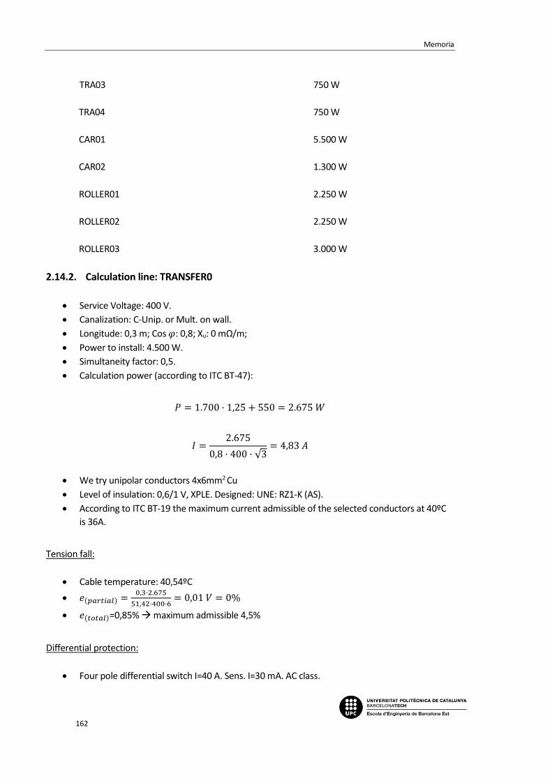
Memoria
162
TRA03 750 W
TRA04 750 W
CAR01 5.500 W
CAR02 1.300 W
ROLLER01 2.250 W
ROLLER02 2.250 W
ROLLER03 3.000 W
2.14.2. Calculation line: TRANSFER0
Service Voltage: 400 V.
Canalization: C-Unip. or Mult. on wall.
Longitude: 0,3 m; Cos 𝜑: 0,8; Xu: 0 mΩ/m;
Power to install: 4.500 W.
Simultaneity factor: 0,5.
Calculation power (according to ITC BT-47):
𝑃 = 1.700 · 1,25 + 550 = 2.675 𝑊
𝐼 =2.675
0,8 · 400 · √3= 4,83 𝐴
We try unipolar conductors 4x6mm2 Cu
Level of insulation: 0,6/1 V, XPLE. Designed: UNE: RZ1-K (AS).
According to ITC BT-19 the maximum current admissible of the selected conductors at 40ºC
is 36A.
Tension fall:
Cable temperature: 40,54ºC
𝑒(𝑝𝑎𝑟𝑡𝑖𝑎𝑙) =0,3·2.675
51,42·400·6= 0,01 𝑉 = 0%
𝑒(𝑡𝑜𝑡𝑎𝑙)=0,85% maximum admissible 4,5%
Differential protection:
Four pole differential switch I=40 A. Sens. I=30 mA. AC class.

Electrification project in a box factory
163
2.14.3. Calculation line: ROLLER04
Service Voltage: 400 V.
Canalization: B1-Unip. tube superf. or Built-in.
Longitude: 35m; Cos 𝜑: 0,8; Xu: 0 mΩ/m; R=1;
Power to install: 2.250 W.
Calculation power (according to ITC BT-47):
𝑃 = 1.700𝑥1,25 + 550 = 2.675 𝑊
𝐼 =2.675
400 · √3 · 0,8 · 1= 4,83𝐴
We try unipolar conductors 4x2,5+TTx2,5mm2 Cu
Level of insulation: 0,6/1 V, XPLE. Designed: UNE: RZ1-K (AS).
According to ITC BT-19 the maximum current admissible of the selected conductors at 40ºC
is 18,5 A.
Outer tube diameter: 20 mm.
Tension fall:
Cable temperature: 42,04ºC
𝑒(𝑝𝑎𝑟𝑡𝑖𝑎𝑙) =35·2675
51,14·400·2,5·1= 1,83𝑉 = 0,46%
𝑒(𝑡𝑜𝑡𝑎𝑙)=1,31% maximum admissible 6,5%
Thermic protection:
Four pole magnetothermic switch I=16 A.
2.14.4. Calculation line: ROLLER05
Service Voltage: 400 V.
Canalization: B1-Unip. tube superf. or Built-in.
Longitude: 38m; Cos 𝜑: 0,8; Xu: 0 mΩ/m; R=1;
Power to install: 2.250 W.
Calculation power (according to ITC BT-47):
𝑃 = 1.700𝑥1,25 + 550 = 2.675 𝑊

Memoria
164
𝐼 =2.675
400 · √3 · 0,8 · 1= 4,83𝐴
We try unipolar conductors 4x2,5+TTx2,5mm2 Cu
Level of insulation: 0,6/1 V, XPLE. Designed: UNE: RZ1-K (AS).
According to ITC BT-19 the maximum current admissible of the selected conductors at 40ºC
is 18,5 A.
Outer tube diameter: 20 mm.
Tension fall:
Cable temperature: 42,04ºC
𝑒(𝑝𝑎𝑟𝑡𝑖𝑎𝑙) =38·2675
51,14·400·2,5·1= 1,99𝑉 = 0,5%
𝑒(𝑡𝑜𝑡𝑎𝑙)=1,35% maximum admissible 6,5%
Thermic protection:
Four pole magnetothermic switch I=16 A.
2.14.5. Calculation line: TRANSFER1
Service Voltage: 400 V.
Canalization: C-Unip. or Mult. on wall.
Longitude: 0,3 m; Cos 𝜑: 0,8; Xu: 0 mΩ/m;
Power to install: 5.500 W.
Simultaneity factor: 0,9.
Calculation power (according to ITC BT-47):
𝑃 = 4.000 · 1,25 + 950 = 5.950 𝑊
𝐼 =2.675
0,8 · 400 · √3= 10,74 𝐴
We try unipolar conductors 4x10mm2 Cu
Level of insulation: 0,6/1 V, XPLE. Designed: UNE: RZ1-K (AS).
According to ITC BT-19 the maximum current admissible of the selected conductors at 40ºC
is 50A.
Tension fall:
Cable temperature: 41,38ºC

Electrification project in a box factory
165
𝑒(𝑝𝑎𝑟𝑡𝑖𝑎𝑙) =0,3·5.950
51,26·400·10= 0,01 𝑉 = 0%
𝑒(𝑡𝑜𝑡𝑎𝑙)=0,85% maximum admissible 4,5%
Differential protection:
Four pole differential switch I=63 A. Sens. I=30 mA. AC class.
2.14.6. Calculation line: TRA01
Service Voltage: 400 V.
Canalization: B1-Unip. tube superf. or Built-in.
Longitude: 25m; Cos 𝜑: 0,8; Xu: 0 mΩ/m; R=1;
Power to install: 4.000 W.
Calculation power (according to ITC BT-47):
𝑃 = 4.000𝑥1,25 = 5.000 𝑊
𝐼 =5.000
400 · √3 · 0,8 · 1= 9,02𝐴
We try unipolar conductors 4x2,5+TTx2,5mm2 Cu
Level of insulation: 0,6/1 V, XPLE. Designed: UNE: RZ1-K (AS).
According to ITC BT-19 the maximum current admissible of the selected conductors at 40ºC
is 18,5 A.
Outer tube diameter: 20 mm.
Tension fall:
Cable temperature: 47,13ºC
𝑒(𝑝𝑎𝑟𝑡𝑖𝑎𝑙) =25·5.000
50,21·400·2,5·1= 2,49𝑉 = 0,62%
𝑒(𝑡𝑜𝑡𝑎𝑙)=1,48% maximum admissible 6,5%
Thermic protection:
Four pole magnetothermic switch I=16 A.
2.14.7. Calculation line: TRA02
Service Voltage: 400 V.
Canalization: B1-Unip. tube superf. or Built-in.
Longitude: 30m; Cos 𝜑: 0,8; Xu: 0 mΩ/m; R=1;

Memoria
166
Power to install: 750 W.
Calculation power (according to ITC BT-47):
𝑃 = 750𝑥1,25 = 937,5 𝑊
𝐼 =937,5
400 · √3 · 0,8 · 1= 1,69𝐴
We try unipolar conductors 4x2,5+TTx2,5mm2 Cu
Level of insulation: 0,6/1 V, XPLE. Designed: UNE: RZ1-K (AS).
According to ITC BT-19 the maximum current admissible of the selected conductors at 40ºC
is 18,5 A.
Outer tube diameter: 20 mm.
Tension fall:
Cable temperature: 40,25ºC
𝑒(𝑝𝑎𝑟𝑡𝑖𝑎𝑙) =30·937,5
51,47·400·2,5·1= 0,55 𝑉 = 0,14%
𝑒(𝑡𝑜𝑡𝑎𝑙)=0,99% maximum admissible 6,5%
Thermic protection:
Four pole magnetothermic switch I=16 A.
2.14.8. Calculation line: TRA03
Service Voltage: 400 V.
Canalization: B1-Unip. tube superf. or Built-in.
Longitude: 32m; Cos 𝜑: 0,8; Xu: 0 mΩ/m; R=1;
Power to install: 750 W.
Calculation power (according to ITC BT-47):
𝑃 = 750𝑥1,25 = 937,5 𝑊
𝐼 =937,5
400 · √3 · 0,8 · 1= 1,69𝐴
We try unipolar conductors 4x2,5+TTx2,5mm2 Cu
Level of insulation: 0,6/1 V, XPLE. Designed: UNE: RZ1-K (AS).
According to ITC BT-19 the maximum current admissible of the selected conductors at 40ºC
is 18,5 A.
Outer tube diameter: 20 mm.
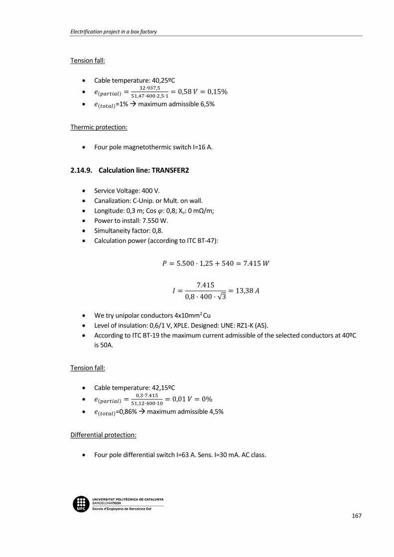
Electrification project in a box factory
167
Tension fall:
Cable temperature: 40,25ºC
𝑒(𝑝𝑎𝑟𝑡𝑖𝑎𝑙) =32·937,5
51,47·400·2,5·1= 0,58 𝑉 = 0,15%
𝑒(𝑡𝑜𝑡𝑎𝑙)=1% maximum admissible 6,5%
Thermic protection:
Four pole magnetothermic switch I=16 A.
2.14.9. Calculation line: TRANSFER2
Service Voltage: 400 V.
Canalization: C-Unip. or Mult. on wall.
Longitude: 0,3 m; Cos 𝜑: 0,8; Xu: 0 mΩ/m;
Power to install: 7.550 W.
Simultaneity factor: 0,8.
Calculation power (according to ITC BT-47):
𝑃 = 5.500 · 1,25 + 540 = 7.415 𝑊
𝐼 =7.415
0,8 · 400 · √3= 13,38 𝐴
We try unipolar conductors 4x10mm2 Cu
Level of insulation: 0,6/1 V, XPLE. Designed: UNE: RZ1-K (AS).
According to ITC BT-19 the maximum current admissible of the selected conductors at 40ºC
is 50A.
Tension fall:
Cable temperature: 42,15ºC
𝑒(𝑝𝑎𝑟𝑡𝑖𝑎𝑙) =0,3·7.415
51,12·400·10= 0,01 𝑉 = 0%
𝑒(𝑡𝑜𝑡𝑎𝑙)=0,86% maximum admissible 4,5%
Differential protection:
Four pole differential switch I=63 A. Sens. I=30 mA. AC class.
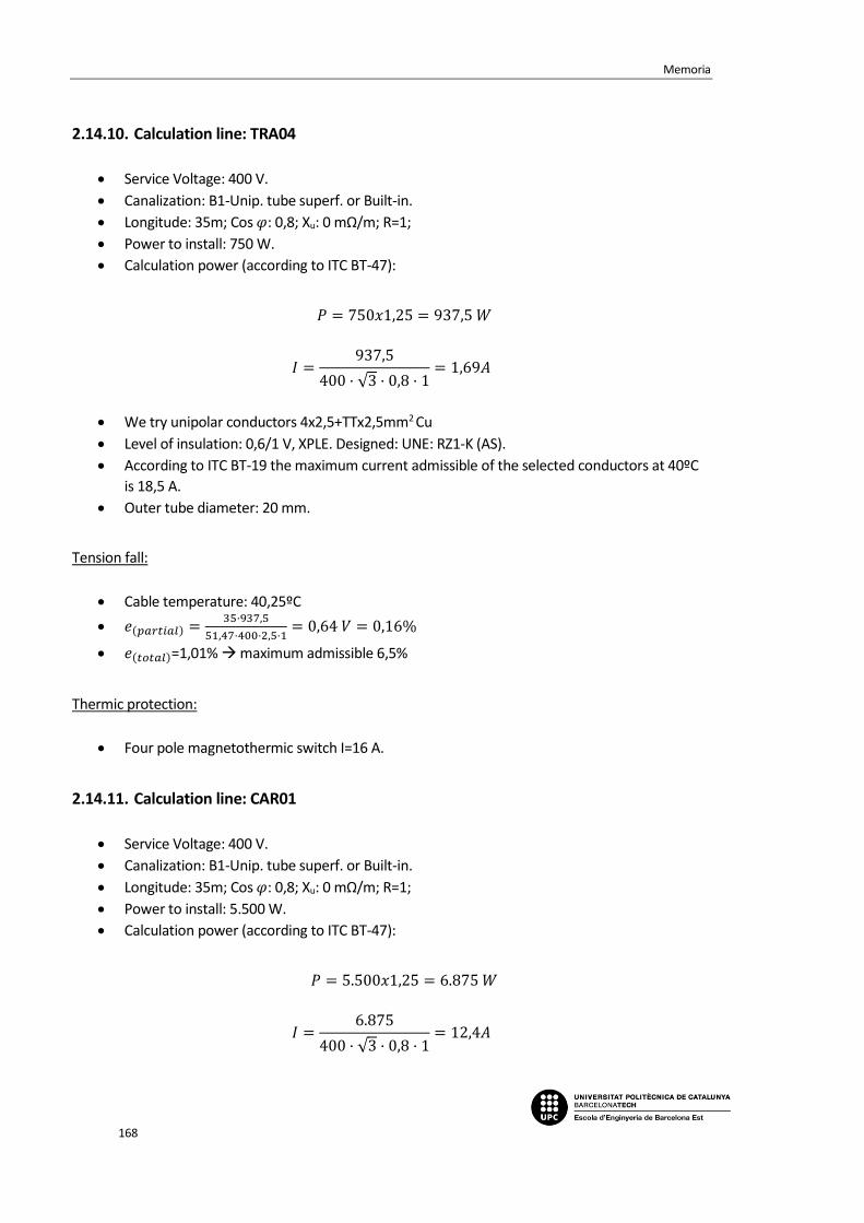
Memoria
168
2.14.10. Calculation line: TRA04
Service Voltage: 400 V.
Canalization: B1-Unip. tube superf. or Built-in.
Longitude: 35m; Cos 𝜑: 0,8; Xu: 0 mΩ/m; R=1;
Power to install: 750 W.
Calculation power (according to ITC BT-47):
𝑃 = 750𝑥1,25 = 937,5 𝑊
𝐼 =937,5
400 · √3 · 0,8 · 1= 1,69𝐴
We try unipolar conductors 4x2,5+TTx2,5mm2 Cu
Level of insulation: 0,6/1 V, XPLE. Designed: UNE: RZ1-K (AS).
According to ITC BT-19 the maximum current admissible of the selected conductors at 40ºC
is 18,5 A.
Outer tube diameter: 20 mm.
Tension fall:
Cable temperature: 40,25ºC
𝑒(𝑝𝑎𝑟𝑡𝑖𝑎𝑙) =35·937,5
51,47·400·2,5·1= 0,64 𝑉 = 0,16%
𝑒(𝑡𝑜𝑡𝑎𝑙)=1,01% maximum admissible 6,5%
Thermic protection:
Four pole magnetothermic switch I=16 A.
2.14.11. Calculation line: CAR01
Service Voltage: 400 V.
Canalization: B1-Unip. tube superf. or Built-in.
Longitude: 35m; Cos 𝜑: 0,8; Xu: 0 mΩ/m; R=1;
Power to install: 5.500 W.
Calculation power (according to ITC BT-47):
𝑃 = 5.500𝑥1,25 = 6.875 𝑊
𝐼 =6.875
400 · √3 · 0,8 · 1= 12,4𝐴
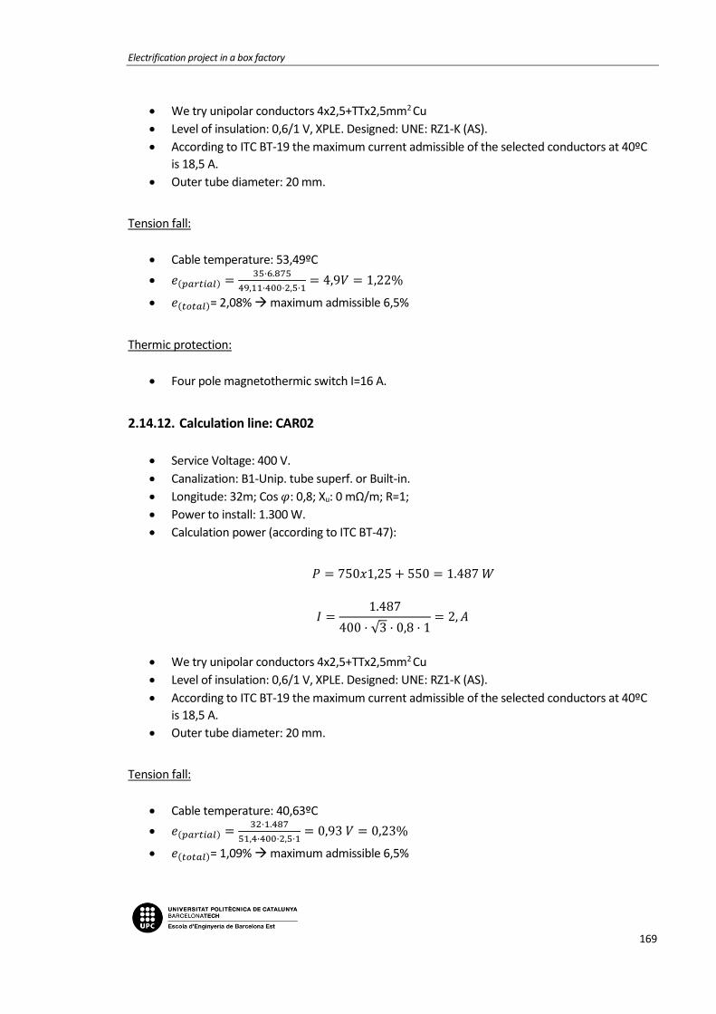
Electrification project in a box factory
169
We try unipolar conductors 4x2,5+TTx2,5mm2 Cu
Level of insulation: 0,6/1 V, XPLE. Designed: UNE: RZ1-K (AS).
According to ITC BT-19 the maximum current admissible of the selected conductors at 40ºC
is 18,5 A.
Outer tube diameter: 20 mm.
Tension fall:
Cable temperature: 53,49ºC
𝑒(𝑝𝑎𝑟𝑡𝑖𝑎𝑙) =35·6.875
49,11·400·2,5·1= 4,9𝑉 = 1,22%
𝑒(𝑡𝑜𝑡𝑎𝑙)= 2,08% maximum admissible 6,5%
Thermic protection:
Four pole magnetothermic switch I=16 A.
2.14.12. Calculation line: CAR02
Service Voltage: 400 V.
Canalization: B1-Unip. tube superf. or Built-in.
Longitude: 32m; Cos 𝜑: 0,8; Xu: 0 mΩ/m; R=1;
Power to install: 1.300 W.
Calculation power (according to ITC BT-47):
𝑃 = 750𝑥1,25 + 550 = 1.487 𝑊
𝐼 =1.487
400 · √3 · 0,8 · 1= 2, 𝐴
We try unipolar conductors 4x2,5+TTx2,5mm2 Cu
Level of insulation: 0,6/1 V, XPLE. Designed: UNE: RZ1-K (AS).
According to ITC BT-19 the maximum current admissible of the selected conductors at 40ºC
is 18,5 A.
Outer tube diameter: 20 mm.
Tension fall:
Cable temperature: 40,63ºC
𝑒(𝑝𝑎𝑟𝑡𝑖𝑎𝑙) =32·1.487
51,4·400·2,5·1= 0,93 𝑉 = 0,23%
𝑒(𝑡𝑜𝑡𝑎𝑙)= 1,09% maximum admissible 6,5%
Memoria
170
Thermic protection:
Four pole magnetothermic switch I=16 A.
2.14.13. Calculation line: TRANSFER3
Service Voltage: 400 V.
Canalization: C-Unip. or Mult. on wall.
Longitude: 0,3 m; Cos 𝜑: 0,8; Xu: 0 mΩ/m;
Power to install: 7.500 W.
Simultaneity factor: 0,5.
Calculation power (according to ITC BT-47):
𝑃 = 1.700 · 1,25 + 2.050 = 4.175 𝑊
𝐼 =4.175
0,8 · 400 · √3= 7,53 𝐴
We try unipolar conductors 4x10mm2 Cu
Level of insulation: 0,6/1 V, XPLE. Designed: UNE: RZ1-K (AS).
According to ITC BT-19 the maximum current admissible of the selected conductors at 40ºC
is 50A.
Tension fall:
Cable temperature: 40,68ºC
𝑒(𝑝𝑎𝑟𝑡𝑖𝑎𝑙) =0,3·4.175
51,39·400·10= 0,01 𝑉 = 0%
𝑒(𝑡𝑜𝑡𝑎𝑙)=0,85% maximum admissible 4,5%
Differential protection:
Four pole differential switch I=63 A. Sens. I=30 mA. AC class.
2.14.14. Calculation line: ROLLER01
Service Voltage: 400 V.
Canalization: B1-Unip. tube superf. or Built-in.
Longitude: 25m; Cos 𝜑: 0,8; Xu: 0 mΩ/m; R=1;
Power to install: 2.250 W.
Calculation power (according to ITC BT-47):

Electrification project in a box factory
171
𝑃 = 1.700𝑥1,25 + 550 = 2.675 𝑊
𝐼 =2.675
400 · √3 · 0,8 · 1= 4,83𝐴
We try unipolar conductors 4x2,5+TTx2,5mm2 Cu
Level of insulation: 0,6/1 V, XPLE. Designed: UNE: RZ1-K (AS).
According to ITC BT-19 the maximum current admissible of the selected conductors at 40ºC
is 18,5 A.
Outer tube diameter: 20 mm.
Tension fall:
Cable temperature: 42,04ºC
𝑒(𝑝𝑎𝑟𝑡𝑖𝑎𝑙) =25·2675
51,14·400·2,5·1= 1,31𝑉 = 0,33%
𝑒(𝑡𝑜𝑡𝑎𝑙)=1,18% maximum admissible 6,5%
Thermic protection:
Four pole magnetothermic switch I=16 A.
2.14.15. Calculation line: ROLLER02
Service Voltage: 400 V.
Canalization: B1-Unip. tube superf. or Built-in.
Longitude: 30m; Cos 𝜑: 0,8; Xu: 0 mΩ/m; R=1;
Power to install: 2.250 W.
Calculation power (according to ITC BT-47):
𝑃 = 1.700𝑥1,25 + 550 = 2.675 𝑊
𝐼 =2.675
400 · √3 · 0,8 · 1= 4,83𝐴
We try unipolar conductors 4x2,5+TTx2,5mm2 Cu
Level of insulation: 0,6/1 V, XPLE. Designed: UNE: RZ1-K (AS).
According to ITC BT-19 the maximum current admissible of the selected conductors at 40ºC
is 18,5 A.
Outer tube diameter: 20 mm.
Tension fall:

Memoria
172
Cable temperature: 42,04ºC
𝑒(𝑝𝑎𝑟𝑡𝑖𝑎𝑙) =30·2675
51,14·400·2,5·1= 1,57𝑉 = 0,39%
𝑒(𝑡𝑜𝑡𝑎𝑙)=1,25% maximum admissible 6,5%
Thermic protection:
Four pole magnetothermic switch I=16 A.
2.14.16. Calculation line: ROLLER03
Service Voltage: 400 V.
Canalization: B1-Unip. tube superf. or Built-in.
Longitude: 32m; Cos 𝜑: 0,8; Xu: 0 mΩ/m; R=1;
Power to install: 3.000 W.
Calculation power (according to ITC BT-47):
𝑃 = 750𝑥1,25 + 2.250 = 3.187,5𝑊
𝐼 =3.187,5
400 · √3 · 0,8 · 1= 5,75𝐴
We try unipolar conductors 4x2,5+TTx2,5mm2 Cu
Level of insulation: 0,6/1 V, XPLE. Designed: UNE: RZ1-K (AS).
According to ITC BT-19 the maximum current admissible of the selected conductors at 40ºC
is 18,5 A.
Outer tube diameter: 20 mm.
Tension fall:
Cable temperature: 42,9ºC
𝑒(𝑝𝑎𝑟𝑡𝑖𝑎𝑙) =32·3.187,5
50,98·400·2,5·1= 2𝑉 = 0,5%
𝑒(𝑡𝑜𝑡𝑎𝑙)=1,35% maximum admissible 6,5%
Thermic protection:
Four pole magnetothermic switch I=16 A.
2.14.17. Bus Bar calculations: SP-TRANSFER
Data
Electrification project in a box factory
173
Metal: Cu.
State of the plates: Bare.
Number of plates per phase: 1.
Distance between plates: d=10 cm.
Distance between supports: L=25 cm.
Short circuit time: 0,5 s.
Used plate
Section: 30 mm2.
Amplitude: 15 mm.
Thickness: 2 mm.
Wx, Ix, Wi, li (cm3, cm4): 0,075 ; 0,0562 ; 0,01; 0,001.
I. admissible of the bus bar: 170 A.
a) Electrodynamic calculation
𝜎𝑚𝑎𝑥 =3,07
2 · 252
60 · 10 · 0,01 · 1= 982,166 ≤ 950,944
𝑘𝑔
𝑐𝑚2 𝐶𝑢
b) Thermal calculation per admissible current
𝐼𝑐𝑎𝑙 = 20,56 𝐴
𝐼𝑎𝑑𝑚 = 140 𝐴
c) Check for thermal request in short circuit
𝐼𝑝𝑐𝑐 = 3,07 𝑘𝐴
𝐼𝑐𝑐𝑐𝑠 =𝐾𝑐 · 𝑆
1000 · √𝑡𝑐𝑐
=164 · 30
1000 · √0,5= 6,96 𝑘𝐴
2.15. Sub-panel SP-EXT
2.15.1. Power demand
-Total installed power:
DOOR01 1.840 W

Memoria
174
DOOR02 1.060 W
BACKUP 1 W
2.15.2. Calculation line: DOOR01
Service Voltage: 400 V.
Canalization: B1-Unip. Superficial tube or Built-in.
Longitude: 35 m; Cos 𝜑: 0,8; Xu: 0 mΩ/m; R: 1;
Power to install: 1.839 W.
Calculation power (according to ITC BT-47):
𝑃 = 1.839 · 1,25 = 2.295,75𝑊
𝐼 =2.295,75
0,8 · 400 · √3 · 1= 4,15 𝐴
We try unipolar conductors 4x2,5+TTx2,5mm2 Cu
Level of insulation: 0,6/1 kV, XPLE. Designed: UNE: RZ1-K (AS).
According to ITC BT-19 the maximum current admissible of the selected conductors at 40ºC
is 18,5A.
Outer tube diameter: 20 mm.
Tension fall:
Cable temperature: 41,51ºC
𝑒(𝑝𝑎𝑟𝑡𝑖𝑎𝑙) =35·2.295,75
51,24·400·2,5= 1,57 𝑉 = 0,39%
𝑒(𝑡𝑜𝑡𝑎𝑙)=1,42% maximum admissible 6,5%
Thermic protection:
Four pole magnetothermic switch I=16 A.
Differential protection:
Four pole differential switch I=25 A. Sens. I=30 mA. AC class.
2.15.3. Calculation line: DOOR02
Service Voltage: 230 V.
Canalization: B1-Unip. Superficial tube or Built-in.
Longitude: 34 m; Cos 𝜑: 0,8; Xu: 0 mΩ/m;R:1;
Power to install:1.060 W.

Electrification project in a box factory
175
Calculation power (According to ITC BT-47):
𝑃 = 1.060 · 1,25 = 1.325 W
𝐼 =1.325
0,8 · 230= 7,2 𝐴
We try unipolar conductors 2x2,5+TTx2,5mm2 Cu
Level of insulation: 0,6/1 V, XPLE. Designed: UNE: RZ1-K (AS).
According to ITC BT-19 the maximum current admissible of the selected conductors at 40ºC
is 21 A.
Outer tube diameter: 20 mm.
Tension fall:
Cable temperature: 43,53ºC
𝑒(𝑝𝑎𝑟𝑡𝑖𝑎𝑙) =2·34·1.325
50,86·230·2,5= 3,08 𝑉 = 1,34%
𝑒(𝑡𝑜𝑡𝑎𝑙)=2,36% maximum admissible 6,5%
Thermic protection:
Four pole magnetothermic switch I=16 A.
Differential protection:
Two pole differential switch I=25 A. Sens. I=30 mA. AC class.
2.15.4. Calculation line: BACKUP
Service Voltage: 400 V.
Canalization: B1-Unip. tube superf. or Built-in.
Longitude: 6 m; Cos 𝜑: 0,8; Xu: 0 mΩ/m;
Power to install: 1 W.
𝑃 = 1 𝑊
𝐼 =1
400 · √3 · 0,8 · 1= 0 𝐴
We try unipolar conductors 4x2,5+TTx2,5mm2 Cu
Level of insulation: 0,6/1 V, XPLE. Designed: UNE: RZ1-K (AS).
According to ITC BT-19 the maximum current admissible of the selected conductors at 40ºC
is 18,5 A.
Memoria
176
Outer tube diameter: 20 mm.
Tension fall:
Cable temperature: 40ºC
𝑒(𝑝𝑎𝑟𝑡𝑖𝑎𝑙) =8·1
51,52·400·2,5= 0𝑉 = 0%
𝑒(𝑡𝑜𝑡𝑎𝑙)=1,53% maximum admissible 6,5%
Thermic protection:
Four pole magnetothermic switch I=16 A.
Differential protection:
Four pole differential switch I=25 A. Sens. I=30 mA. AC class.
2.15.5. Bus Bar calculations: SP-EXT
Data
Metal: Cu.
State of the plates: Bare.
Number of plates per phase: 1.
Distance between plates: d=10 cm.
Distance between supports: L=25 cm.
Short circuit time: 0,5 s.
Used plate
Section: 24 mm2.
Amplitude: 12 mm.
Thickness: 2 mm.
Wx, Ix, Wi, li (cm3, cm4): 0,048 ; 0,0288 ; 0,008; 0,0008.
I. admissible of the bus bar: 110 A.
a) Electrodynamic calculation
𝜎𝑚𝑎𝑥 =0,52
2 · 252
60 · 10 · 0,008 · 1= 35,403 ≤ 1200
𝑘𝑔
𝑐𝑚2 𝐶𝑢

Electrification project in a box factory
177
b) Thermal calculation per admissible current
𝐼𝑐𝑎𝑙 = 5,02 𝐴
𝐼𝑎𝑑𝑚 = 110 𝐴
c) Check for thermal request in short circuit
𝐼𝑝𝑐𝑐 = 0,52 𝑘𝐴
𝐼𝑐𝑐𝑐𝑠 =𝐾𝑐 · 𝑆
1000 · √𝑡𝑐𝑐
=164 · 24
1000 · √0,5= 5,57 𝑘𝐴
2.16. Sub-panel SP-SUCTION
2.16.1. Power demand
-Total installed power:
SP-SUC-VENT 37.022 W
FTM1500 15.000 W
VAL-VEOLAR1500 200 W
SWITCHBOARD 20 W
PLC 200 W
SIGNAL 24V 50 W
BACKUP 1 W
BACKUP 1 W
2.16.2. Calculation line: SP-SUC-VENT
Service Voltage: 400 V.
Canalization: F-Unip. O Mult. Suports.
Longitude: 100 m; Cos 𝜑: 0,8; Xu: 0 mΩ/m;
Power to install: 37.022 W.

Memoria
178
Simultaneity factor: 1.
Calculation power (according to ITC BT-47):
𝑃 = 37.000 · 1,25 + 22 = 46.272 𝑊
𝐼 =46.272
0,8 · 400 · √3= 83,49 𝐴
We try unipolar conductors 4x35+TTx16mm2 Cu
Level of insulation: 0,6/1 kV, XPLE. Designed: UNE: RZ1-K (AS).
According to ITC BT-19 the maximum current admissible of the selected conductors at 40ºC
is 144 A.
Tension fall:
Cable temperature: 56,81ºC
𝑒(𝑝𝑎𝑟𝑡𝑖𝑎𝑙) =100·46.272
48,55·400·35= 6,81 𝑉 = 1,7%
𝑒(𝑡𝑜𝑡𝑎𝑙)=3,9% maximum admissible 4,5%
Thermic protection origin of line:
Four pole automatic switch In: 100 A. Thermic regulation Ireg= 100 A.
Thermic protection at the end of the line
Current of cut in load: I=100 A.
2.16.3. Calculation line: FTM1500
Service Voltage: 400 V.
Canalization: B1-Unip. Superficial tube or Built-in.
Longitude: 15 m; Cos 𝜑: 0,8; Xu: 0 mΩ/m; R: 1;
Power to install: 15.000 W.
Calculation power (according to ITC BT-47):
𝑃 = 15.000 · 1,25 = 18.750 𝑊
𝐼 =18.750
0,85 · 400 · √3 · 1= 33,83 𝐴
We try unipolar conductors 4x10+TTx10mm2 Cu
Level of insulation: 0,6/1 kV, XPLE. Designed: UNE: RZ1-K (AS).
According to ITC BT-19 the maximum current admissible of the selected conductors at 40ºC
is 44A.

Electrification project in a box factory
179
Outer tube diameter: 32 mm.
Tension fall:
Cable temperature: 57,73ºC
𝑒(𝑝𝑎𝑟𝑡𝑖𝑎𝑙) =15·18.750
48,4·400·10= 1,45 𝑉 = 0,36%
𝑒(𝑡𝑜𝑡𝑎𝑙)=2,57% maximum admissible 6,5%
Thermic protection:
Four pole magnetothermic switch I=40 A.
Differential protection:
Four pole differential switch I=40 A. Sens. I=300 mA. AC class.
2.16.4. Calculation line: SUCTION 1
Service Voltage: 230 V.
Canalization: C-Unip. or Mult. on wall.
Longitude: 0,3 m; Cos 𝜑: 0,8; Xu: 0 mΩ/m;
Power to install: 220 W.
Simultaneity factor: 1.
Calculation power (according to ITC BT-44):
𝑃 = 220 𝑊
𝐼 =220
230 · 0,8= 1,2𝐴
We try unipolar conductors 2x4mm2 Cu
Level of insulation: 0,6/1 V, XPLE. Designed: UNE: RZ1-K (AS).
According to ITC BT-19 the maximum current admissible of the selected conductors at 40ºC
is 31 A.
Tension fall:
Cable temperature: 40,04ºC
𝑒(𝑝𝑎𝑟𝑡𝑖𝑎𝑙) =2·0,3·220
51,51·230·4= 0𝑉 = 0%
𝑒(𝑡𝑜𝑡𝑎𝑙)=2,2% maximum admissible 4,5%
Differential protection:
Memoria
180
Two pole differential switch I=40 A. Sens. I=30 mA. AC class.
2.16.5. Calculation line: VAL-VEOLAR1500
Service Voltage: 230 V.
Canalization: B1-Unip. tube superf. or built-in.
Longitude: 20 m; Cos 𝜑: 0,8; Xu: 0 mΩ/m;
Power to install: 200 W.
Calculation power: 200 W
𝐼 =200
230 · 0,8= 1,09 𝐴
We try unipolar conductors 2x2,5+TTx2,5mm2 Cu
Level of insulation: 0,6/1 V, XPLE. Designed: UNE: RZ1-K (AS).
According to ITC BT-19 the maximum current admissible of the selected conductors at 40ºC
is 21 A.
Outer tube diameter: 20 mm.
Tension fall:
Cable temperature: 40,08ºC
𝑒(𝑝𝑎𝑟𝑡𝑖𝑎𝑙) =2·20·200
51,5·230·2,5= 0,27𝑉 = 0,12%
𝑒(𝑡𝑜𝑡𝑎𝑙)=2,32% maximum admissible 6,5%
Thermic protection:
Two pole magnetothermic switch I=16 A.
2.16.6. Calculation line: SWITCHBOARD
Service Voltage: 230 V.
Canalization: B1-Unip. tube superf. or Built-in.
Longitude: 15 m; Cos 𝜑: 0,8; Xu: 0 mΩ/m;
Power to install: 20 W.
Calculation power: 20 𝑊
𝐼 =20
230 · 0,8= 0,11 𝐴
We try unipolar conductors 2x2,5+TTx2,5mm2 Cu

Electrification project in a box factory
181
Level of insulation: 0,6/1 V, XPLE. Designed: UNE: RZ1-K (AS).
According to ITC BT-19 the maximum current admissible of the selected conductors at 40ºC
is 21 A.
Outer tube diameter: 20 mm.
Tension fall:
Cable temperature: 40ºC
𝑒(𝑝𝑎𝑟𝑡𝑖𝑎𝑙) =2·15·20
51,52·230·2,5= 0,02𝑉 = 0,01%
𝑒(𝑡𝑜𝑡𝑎𝑙)=2,21% maximum admissible 6,5%
Thermic protection:
Two pole magnetothermic switch I=10 A.
2.16.7. Calculation line: SUCTION 2
Service Voltage: 230 V.
Canalization: C-Unip. or Mult. on wall.
Longitude: 0,3 m; Cos 𝜑: 0,8; Xu: 0 mΩ/m;
Power to install: 250 W.
Simultaneity factor: 1.
Calculation power (according to ITC BT-44):
𝑃 = 250 𝑊
𝐼 =250
230 · 0,8= 1,36𝐴
We try unipolar conductors 2x4mm2 Cu
Level of insulation: 0,6/1 V, XPLE. Designed: UNE: RZ1-K (AS).
According to ITC BT-19 the maximum current admissible of the selected conductors at 40ºC
is 31 A.
Tension fall:
Cable temperature: 40,06ºC
𝑒(𝑝𝑎𝑟𝑡𝑖𝑎𝑙) =2·0,3·250
51,51·230·4= 0𝑉 = 0%
𝑒(𝑡𝑜𝑡𝑎𝑙)=2,2% maximum admissible 4,5%
Differential protection:
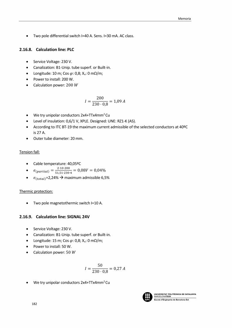
Memoria
182
Two pole differential switch I=40 A. Sens. I=30 mA. AC class.
2.16.8. Calculation line: PLC
Service Voltage: 230 V.
Canalization: B1-Unip. tube superf. or Built-in.
Longitude: 10 m; Cos 𝜑: 0,8; Xu: 0 mΩ/m;
Power to install: 200 W.
Calculation power: 200 𝑊
𝐼 =200
230 · 0,8= 1,09 𝐴
We try unipolar conductors 2x4+TTx4mm2 Cu
Level of insulation: 0,6/1 V, XPLE. Designed: UNE: RZ1-K (AS).
According to ITC BT-19 the maximum current admissible of the selected conductors at 40ºC
is 27 A.
Outer tube diameter: 20 mm.
Tension fall:
Cable temperature: 40,05ºC
𝑒(𝑝𝑎𝑟𝑡𝑖𝑎𝑙) =2·10·200
51,51·230·4= 0,08𝑉 = 0,04%
𝑒(𝑡𝑜𝑡𝑎𝑙)=2,24% maximum admissible 6,5%
Thermic protection:
Two pole magnetothermic switch I=10 A.
2.16.9. Calculation line: SIGNAL 24V
Service Voltage: 230 V.
Canalization: B1-Unip. tube superf. or Built-in.
Longitude: 15 m; Cos 𝜑: 0,8; Xu: 0 mΩ/m;
Power to install: 50 W.
Calculation power: 50 𝑊
𝐼 =50
230 · 0,8= 0,27 𝐴
We try unipolar conductors 2x4+TTx4mm2 Cu
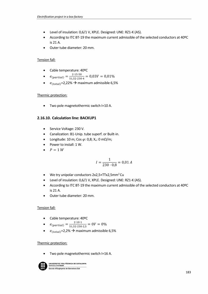
Electrification project in a box factory
183
Level of insulation: 0,6/1 V, XPLE. Designed: UNE: RZ1-K (AS).
According to ITC BT-19 the maximum current admissible of the selected conductors at 40ºC
is 21 A.
Outer tube diameter: 20 mm.
Tension fall:
Cable temperature: 40ºC
𝑒(𝑝𝑎𝑟𝑡𝑖𝑎𝑙) =2·15·50
51,52·230·4= 0,03𝑉 = 0,01%
𝑒(𝑡𝑜𝑡𝑎𝑙)=2,22% maximum admissible 6,5%
Thermic protection:
Two pole magnetothermic switch I=10 A.
2.16.10. Calculation line: BACKUP1
Service Voltage: 230 V.
Canalization: B1-Unip. tube superf. or Built-in.
Longitude: 10 m; Cos 𝜑: 0,8; Xu: 0 mΩ/m;
Power to install: 1 W.
𝑃 = 1 𝑊
𝐼 =1
230 · 0,8= 0,01 𝐴
We try unipolar conductors 2x2,5+TTx2,5mm2 Cu
Level of insulation: 0,6/1 V, XPLE. Designed: UNE: RZ1-K (AS).
According to ITC BT-19 the maximum current admissible of the selected conductors at 40ºC
is 21 A.
Outer tube diameter: 20 mm.
Tension fall:
Cable temperature: 40ºC
𝑒(𝑝𝑎𝑟𝑡𝑖𝑎𝑙) =2·10·1
51,52·230·2,5= 0𝑉 = 0%
𝑒(𝑡𝑜𝑡𝑎𝑙)=2,2% maximum admissible 6,5%
Thermic protection:
Two pole magnetothermic switch I=16 A.
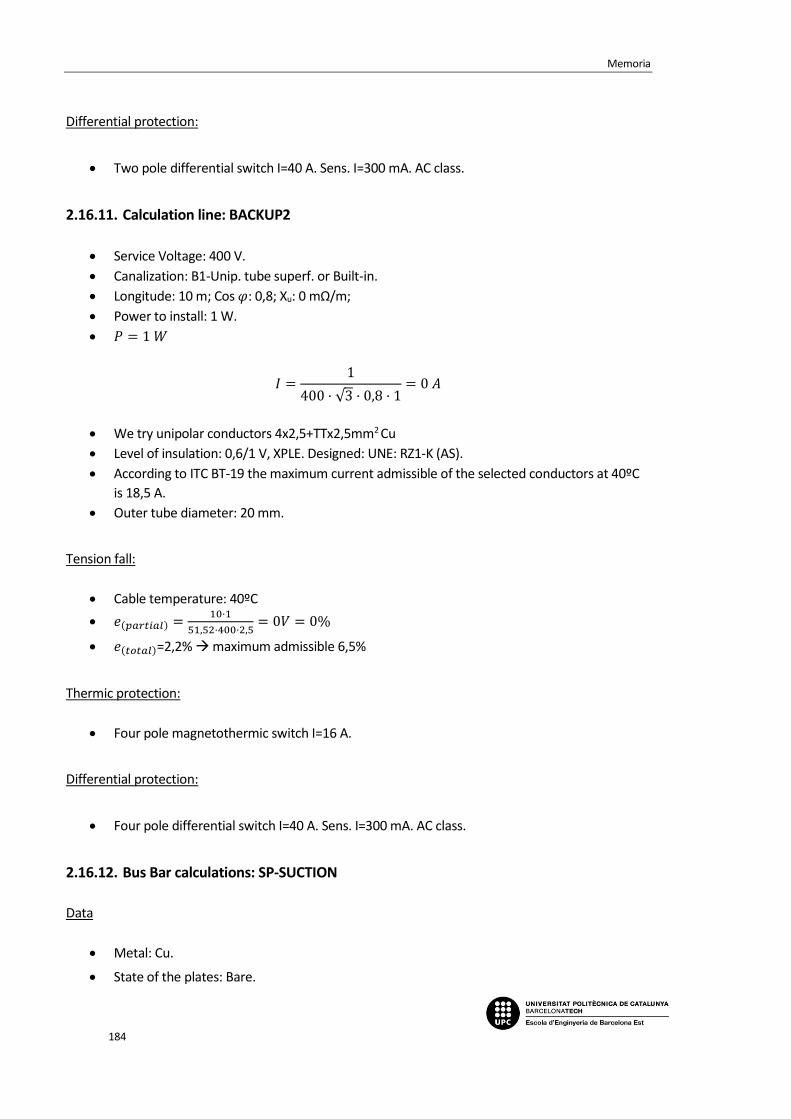
Memoria
184
Differential protection:
Two pole differential switch I=40 A. Sens. I=300 mA. AC class.
2.16.11. Calculation line: BACKUP2
Service Voltage: 400 V.
Canalization: B1-Unip. tube superf. or Built-in.
Longitude: 10 m; Cos 𝜑: 0,8; Xu: 0 mΩ/m;
Power to install: 1 W.
𝑃 = 1 𝑊
𝐼 =1
400 · √3 · 0,8 · 1= 0 𝐴
We try unipolar conductors 4x2,5+TTx2,5mm2 Cu
Level of insulation: 0,6/1 V, XPLE. Designed: UNE: RZ1-K (AS).
According to ITC BT-19 the maximum current admissible of the selected conductors at 40ºC
is 18,5 A.
Outer tube diameter: 20 mm.
Tension fall:
Cable temperature: 40ºC
𝑒(𝑝𝑎𝑟𝑡𝑖𝑎𝑙) =10·1
51,52·400·2,5= 0𝑉 = 0%
𝑒(𝑡𝑜𝑡𝑎𝑙)=2,2% maximum admissible 6,5%
Thermic protection:
Four pole magnetothermic switch I=16 A.
Differential protection:
Four pole differential switch I=40 A. Sens. I=300 mA. AC class.
2.16.12. Bus Bar calculations: SP-SUCTION
Data
Metal: Cu.
State of the plates: Bare.

Electrification project in a box factory
185
Number of plates per phase: 1.
Distance between plates: d=10 cm.
Distance between supports: L=25 cm.
Short circuit time: 0,5 s.
Used plate
Section: 40 mm2.
Amplitude: 20 mm.
Thickness: 2 mm.
Wx, Ix, Wi, li (cm3, cm4): 0,133 ; 0,133 ; 0,0133; 0,0013.
I. admissible of the bus bar: 185 A.
a) Electrodynamic calculation
𝜎𝑚𝑎𝑥 =3,41
2 · 252
60 · 10 · 0,0133 · 1= 909,505 ≤ 1.200
𝑘𝑔
𝑐𝑚2 𝐶𝑢
b) Thermal calculation per admissible current
𝐼𝑐𝑎𝑙 = 111,4 𝐴
𝐼𝑎𝑑𝑚 = 185 𝐴
c) Check for thermal request in short circuit
𝐼𝑝𝑐𝑐 = 3,41 𝑘𝐴
𝐼𝑐𝑐𝑐𝑠 =𝐾𝑐 · 𝑆
1000 · √𝑡𝑐𝑐
=164 · 40
1000 · √0,5= 9,28 𝑘𝐴
2.17. Sub-panel SP-SUC-VENT
2.17.1. Power demand
-Total installed power:
CUT 37.000 W
SWITCHBOARD 20 W
BACKUP 1 W
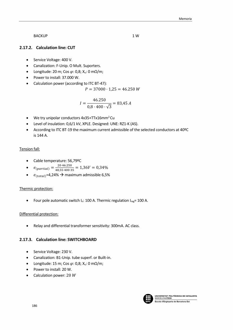
Memoria
186
BACKUP 1 W
2.17.2. Calculation line: CUT
Service Voltage: 400 V.
Canalization: F-Unip. O Mult. Suporters.
Longitude: 20 m; Cos 𝜑: 0,8; Xu: 0 mΩ/m;
Power to install: 37.000 W.
Calculation power (according to ITC BT-47):
𝑃 = 37000 · 1,25 = 46.250 𝑊
𝐼 =46.250
0,8 · 400 · √3= 83,45 𝐴
We try unipolar conductors 4x35+TTx16mm2 Cu
Level of insulation: 0,6/1 kV, XPLE. Designed: UNE: RZ1-K (AS).
According to ITC BT-19 the maximum current admissible of the selected conductors at 40ºC
is 144 A.
Tension fall:
Cable temperature: 56,79ºC
𝑒(𝑝𝑎𝑟𝑡𝑖𝑎𝑙) =20·46.250
48,55·400·35= 1,36𝑉 = 0,34%
𝑒(𝑡𝑜𝑡𝑎𝑙)=4,24% maximum admissible 6,5%
Thermic protection:
Four pole automatic switch In: 100 A. Thermic regulation Ireg= 100 A.
Differential protection:
Relay and differential transformer sensitivity: 300mA. AC class.
2.17.3. Calculation line: SWITCHBOARD
Service Voltage: 230 V.
Canalization: B1-Unip. tube superf. or Built-in.
Longitude: 15 m; Cos 𝜑: 0,8; Xu: 0 mΩ/m;
Power to install: 20 W.
Calculation power: 20 𝑊

Electrification project in a box factory
187
𝐼 =20
230 · 0,7= 0,11 𝐴
We try unipolar conductors 2x2,5+TTx2,5mm2 Cu
Level of insulation: 0,6/1 V, XPLE. Designed: UNE: RZ1-K (AS).
According to ITC BT-19 the maximum current admissible of the selected conductors at 40ºC
is 21 A.
Outer tube diameter: 20 mm.
Tension fall:
Cable temperature: 40ºC
𝑒(𝑝𝑎𝑟𝑡𝑖𝑎𝑙) =2·15·20
51,52·230·2,5= 0,02𝑉 = 0,01%
𝑒(𝑡𝑜𝑡𝑎𝑙)=3,91% maximum admissible 6,5%
Thermic protection:
Two pole magnetothermic switch I=10 A.
Differential protection:
Two pole differential switch I=25 A. Sens. I=300 mA. AC class.
2.17.4. Calculation line: BACKUP1
Service Voltage: 230 V.
Canalization: B1-Unip. tube superf. or Built-in.
Longitude: 10 m; Cos 𝜑: 0,8; Xu: 0 mΩ/m;
Power to install: 1 W.
𝑃 = 1 𝑊
𝐼 =1
230 · 0,8= 0,01 𝐴
We try unipolar conductors 2x2,5+TTx2,5mm2 Cu
Level of insulation: 0,6/1 V, XPLE. Designed: UNE: RZ1-K (AS).
According to ITC BT-19 the maximum current admissible of the selected conductors at 40ºC
is 21 A.
Outer tube diameter: 20 mm.
Tension fall:

Memoria
188
Cable temperature: 40ºC
𝑒(𝑝𝑎𝑟𝑡𝑖𝑎𝑙) =2·10·1
51,52·230·2,5= 0𝑉 = 0%
𝑒(𝑡𝑜𝑡𝑎𝑙)=3,9% maximum admissible 6,5%
Thermic protection:
Two pole magnetothermic switch I=16 A.
Differential protection:
Two pole differential switch I=40 A. Sens. I=300 mA. AC class.
2.17.5. Calculation line: BACKUP2
Service Voltage: 400 V.
Canalization: B1-Unip. tube superf. or Built-in.
Longitude: 10 m; Cos 𝜑: 0,8; Xu: 0 mΩ/m;
Power to install: 1 W.
𝑃 = 1 𝑊
𝐼 =1
400 · √3 · 0,8 · 1= 0 𝐴
We try unipolar conductors 4x2,5+TTx2,5mm2 Cu
Level of insulation: 0,6/1 V, XPLE. Designed: UNE: RZ1-K (AS).
According to ITC BT-19 the maximum current admissible of the selected conductors at 40ºC
is 18,5 A.
Outer tube diameter: 20 mm.
Tension fall:
Cable temperature: 40ºC
𝑒(𝑝𝑎𝑟𝑡𝑖𝑎𝑙) =10·1
51,52·400·2,5= 0𝑉 = 0%
𝑒(𝑡𝑜𝑡𝑎𝑙)=3,9% maximum admissible 6,5%
Thermic protection:
Four pole magnetothermic switch I=16 A.
Differential protection:

Electrification project in a box factory
189
Four pole differential switch I=40 A. Sens. I=300 mA. AC class.
2.17.6. Bus Bar calculations: SP-SUC-VENT
Data
Metal: Cu.
State of the plates: Bare.
Number of plates per phase: 1.
Distance between plates: d=10 cm.
Distance between supports: L=25 cm.
Short circuit time: 0,5 s.
Used plate
Section: 24 mm2.
Amplitude: 12 mm.
Thickness: 2 mm.
Wx, Ix, Wi, li (cm3, cm4): 0,048 ; 0,0288 ; 0,008; 0,0008.
I. admissible of the bus bar: 110 A.
a) Electrodynamic calculation
𝜎𝑚𝑎𝑥 =1,53
2 · 252
60 · 10 · 0,008 · 1= 305,158 ≤ 1200
𝑘𝑔
𝑐𝑚2 𝐶𝑢
b) Thermal calculation per admissible current
𝐼𝑐𝑎𝑙 = 83,49 𝐴
𝐼𝑎𝑑𝑚 = 110 𝐴
c) Check for thermal request in short circuit
𝐼𝑝𝑐𝑐 = 1,53 𝑘𝐴
𝐼𝑐𝑐𝑐𝑠 =𝐾𝑐 · 𝑆
1000 · √𝑡𝑐𝑐
=164 · 24
1000 · √0,5= 5,57 𝑘𝐴
Memoria
190
2.18. Sub-panel SP-TOILETS
2.18.1. Power demand
-Total installed power:
LT01 300 W
LT02 340 W
EMERGENCY 50 W
HDRY01 2.100 W
HDRY02 2.100 W
HDRY03 2.100 W
HDRY04 2.100 W
AIR01 690 W
BACKUP1 1 W
BACKUP2 1 W
AUTDOOR 1.000 W
2.18.2. Calculation line: TOILETS 1
Service Voltage: 230 V.
Canalization: C-Unip. or Mult. on wall.
Longitude: 0,3 m; Cos 𝜑: 0,8; Xu: 0 mΩ/m;
Power to install: 690 W.
Simultaneity factor: 0,5.
Calculation power (according to ITC BT-44):
𝑃 = 621 𝑊
𝐼 =621
230 · 0,8= 3,38𝐴
We try unipolar conductors 2x4mm2 Cu
Level of insulation: 0,6/1 V, XPLE. Designed: UNE: RZ1-K (AS).
Electrification project in a box factory
191
According to ITC BT-19 the maximum current admissible of the selected conductors at 40ºC
is 31 A.
Tension fall:
Cable temperature: 40,36ºC
𝑒(𝑝𝑎𝑟𝑡𝑖𝑎𝑙) =2·0,3·621
51,45·230·4= 0,01𝑉 = 0%
𝑒(𝑡𝑜𝑡𝑎𝑙)=0,97% maximum admissible 4,5%
Differential protection:
Two pole differential switch I=40 A. Sens. I=30 mA. AC class.
2.18.3. Calculation line: LT01
Service Voltage: 230 V.
Canalization: B1-Unip. tube superf. or Built-in.
Longitude: 30 m; Cos 𝜑: 1; Xu: 0 mΩ/m;
Power to install: 300 W.
Calculation power (according to ITC BT-44):
𝑃 = 300 · 1,8 = 540 𝑊
𝐼 =540
230= 2,35 𝐴
We try unipolar conductors 2x1,5+TTx1,5mm2 Cu
Level of insulation: 0,6/1 V, XPLE. Designed: UNE: RZ1-K (AS).
According to ITC BT-19 the maximum current admissible of the selected conductors at 40ºC
is 15 A.
Outer tube diameter: 16 mm.
Tension fall:
Cable temperature: 40,73ºC
𝑒(𝑝𝑎𝑟𝑡𝑖𝑎𝑙) =2·30·540
51,38·230·1,5= 1,83𝑉 = 0,79%
𝑒(𝑡𝑜𝑡𝑎𝑙)=1,76% maximum admissible 4,5%
Thermic protection:
Two pole magnetothermic switch I=10 A.

Memoria
192
2.18.4. Calculation line: LT02
Service Voltage: 230 V.
Canalization: B1-Unip. tube superf. or Built-in.
Longitude: 30 m; Cos 𝜑: 1; Xu: 0 mΩ/m;
Power to install: 340 W.
Calculation power (according to ITC BT-44):
𝑃 = 340 · 1,8 = 612 𝑊
𝐼 =612
230= 2,66 𝐴
We try unipolar conductors 2x1,5+TTx1,5mm2 Cu
Level of insulation: 0,6/1 V, XPLE. Designed: UNE: RZ1-K (AS).
According to ITC BT-19 the maximum current admissible of the selected conductors at 40ºC
is 15 A.
Outer tube diameter: 16 mm.
Tension fall:
Cable temperature: 40,94ºC
𝑒(𝑝𝑎𝑟𝑡𝑖𝑎𝑙) =2·30·612
51,34·230·1,5= 2,07𝑉 = 0,9%
𝑒(𝑡𝑜𝑡𝑎𝑙)=1,87% maximum admissible 4,5%
Thermic protection:
Two pole magnetothermic switch I=10 A.
2.18.5. Calculation line: EMERGENCY
Service Voltage: 230 V.
Canalization: B1-Unip. tube superf. or Built-in.
Longitude: 20 m; Cos 𝜑: 1; Xu: 0 mΩ/m;
Power to install: 50 W.
Calculation power (according to ITC BT-44):
𝑃 = 50 · 1,8 = 90 𝑊
𝐼 =90
230= 0,39 𝐴

Electrification project in a box factory
193
We try unipolar conductors 2x1,5+TTx1,5mm2 Cu
Level of insulation: 0,6/1 V, XPLE. Designed: UNE: RZ1-K (AS).
According to ITC BT-19 the maximum current admissible of the selected conductors at 40ºC
is 15 A.
Outer tube diameter: 16 mm.
Tension fall:
Cable temperature: 40,02ºC
𝑒(𝑝𝑎𝑟𝑡𝑖𝑎𝑙) =2·20·90
51,51·230·1,5= 0,2𝑉 = 0,09%
𝑒(𝑡𝑜𝑡𝑎𝑙)=1,05% maximum admissible 4,5%
Thermic protection:
Two pole magnetothermic switch I=10 A.
2.18.6. Calculation line: TOILETS 2
Service Voltage: 230 V.
Canalization: C-Unip. or Mult. on wall.
Longitude: 0,3 m; Cos 𝜑: 0,8; Xu: 0 mΩ/m;
Power to install: 4.200 W.
Simultaneity factor: 0,5.
Calculation power (according to ITC BT-44):
𝑃 = 2.100 𝑊
𝐼 =2.100
230 · 0,8= 11,41𝐴
We try unipolar conductors 2x6mm2 Cu
Level of insulation: 0,6/1 V, XPLE. Designed: UNE: RZ1-K (AS).
According to ITC BT-19 the maximum current admissible of the selected conductors at 40ºC
is 40 A.
Tension fall:
Cable temperature: 42,44ºC
𝑒(𝑝𝑎𝑟𝑡𝑖𝑎𝑙) =2·0,3·2.100
51,06·230·6= 0,02𝑉 = 0,01%
𝑒(𝑡𝑜𝑡𝑎𝑙)=0,97% maximum admissible 4,5%
Differential protection:

Memoria
194
Two pole differential switch I=40 A. Sens. I=30 mA. AC class.
2.18.7. Calculation line: HDRY01
Service Voltage: 230 V.
Canalization: B1-Unip. tube superf. or Built-in.
Longitude: 15 m; Cos 𝜑: 0,8; Xu: 0 mΩ/m;
Power to install: 2.100 W.
Calculation power: 2.100 𝑊
𝐼 =2.100
0,8 · 230= 11,41 𝐴
We try unipolar conductors 2x2,5+TTx2,5mm2 Cu
Level of insulation: 0,6/1 V, XPLE. Designed: UNE: RZ1-K (AS).
According to ITC BT-19 the maximum current admissible of the selected conductors at 40ºC
is 21 A.
Outer tube diameter: 20 mm.
Tension fall:
Cable temperature: 48,86ºC
𝑒(𝑝𝑎𝑟𝑡𝑖𝑎𝑙) =2·15·2.100
49,91·230·2,5= 2,2𝑉 = 0,95%
𝑒(𝑡𝑜𝑡𝑎𝑙)=1,92% maximum admissible 6,5%
Thermic protection:
Two pole magnetothermic switch I=16 A.
2.18.8. Calculation line: HDRY02
Service Voltage: 230 V.
Canalization: B1-Unip. tube superf. or Built-in.
Longitude: 20 m; Cos 𝜑: 0,8; Xu: 0 mΩ/m;
Power to install: 2.100 W.
Calculation power: 2.100 𝑊
𝐼 =2.100
0,8 · 230= 11,41 𝐴
We try unipolar conductors 2x2,5+TTx2,5mm2 Cu
Electrification project in a box factory
195
Level of insulation: 0,6/1 V, XPLE. Designed: UNE: RZ1-K (AS).
According to ITC BT-19 the maximum current admissible of the selected conductors at 40ºC
is 21 A.
Outer tube diameter: 20 mm.
Tension fall:
Cable temperature: 48,86ºC
𝑒(𝑝𝑎𝑟𝑡𝑖𝑎𝑙) =2·20·2.100
49,91·230·2,5= 2,93𝑉 = 1,27%
𝑒(𝑡𝑜𝑡𝑎𝑙)=2,24% maximum admissible 6,5%
Thermic protection:
Two pole magnetothermic switch I=16 A.
2.18.9. Calculation line: TOILETS 3
Service Voltage: 230 V.
Canalization: C-Unip. or Mult. on wall.
Longitude: 0,3 m; Cos 𝜑: 0,8; Xu: 0 mΩ/m;
Power to install: 4.200 W.
Simultaneity factor: 0,5.
Calculation power (according to ITC BT-44):
𝑃 = 2.100 𝑊
𝐼 =2.100
230 · 0,8= 11,41𝐴
We try unipolar conductors 2x6mm2 Cu
Level of insulation: 0,6/1 V, XPLE. Designed: UNE: RZ1-K (AS).
According to ITC BT-19 the maximum current admissible of the selected conductors at 40ºC
is 40 A.
Tension fall:
Cable temperature: 42,44ºC
𝑒(𝑝𝑎𝑟𝑡𝑖𝑎𝑙) =2·0,3·2.100
51,06·230·6= 0,02𝑉 = 0,01%
𝑒(𝑡𝑜𝑡𝑎𝑙)=0,97% maximum admissible 4,5%
Differential protection:

Memoria
196
Two pole differential switch I=40 A. Sens. I=30 mA. AC class.
2.18.10. Calculation line: HDRY03
Service Voltage: 230 V.
Canalization: B1-Unip. tube superf. or Built-in.
Longitude: 15 m; Cos 𝜑: 0,8; Xu: 0 mΩ/m;
Power to install: 2.100 W.
Calculation power: 2.100 𝑊
𝐼 =2.100
0,8 · 230= 11,41 𝐴
We try unipolar conductors 2x2,5+TTx2,5mm2 Cu
Level of insulation: 0,6/1 V, XPLE. Designed: UNE: RZ1-K (AS).
According to ITC BT-19 the maximum current admissible of the selected conductors at 40ºC
is 21 A.
Outer tube diameter: 20 mm.
Tension fall:
Cable temperature: 48,86ºC
𝑒(𝑝𝑎𝑟𝑡𝑖𝑎𝑙) =2·15·2.100
49,91·230·2,5= 2,2𝑉 = 0,95%
𝑒(𝑡𝑜𝑡𝑎𝑙)=1,92% maximum admissible 6,5%
Thermic protection:
Two pole magnetothermic switch I=16 A.
2.18.11. Calculation line: HDRY04
Service Voltage: 230 V.
Canalization: B1-Unip. tube superf. or Built-in.
Longitude: 20 m; Cos 𝜑: 0,8; Xu: 0 mΩ/m;
Power to install: 2.100 W.
Calculation power: 2.100 𝑊
𝐼 =2.100
0,8 · 230= 11,41 𝐴
We try unipolar conductors 2x2,5+TTx2,5mm2 Cu

Electrification project in a box factory
197
Level of insulation: 0,6/1 V, XPLE. Designed: UNE: RZ1-K (AS).
According to ITC BT-19 the maximum current admissible of the selected conductors at 40ºC
is 21 A.
Outer tube diameter: 20 mm.
Tension fall:
Cable temperature: 48,86ºC
𝑒(𝑝𝑎𝑟𝑡𝑖𝑎𝑙) =2·20·2.100
49,91·230·2,5= 2,93𝑉 = 1,27%
𝑒(𝑡𝑜𝑡𝑎𝑙)=2,24% maximum admissible 6,5%
Thermic protection:
Two pole magnetothermic switch I=16 A.
2.18.12. Calculation line: AIR01
Service Voltage: 230 V.
Canalization: B1-Unip. tube superf. or Built-in.
Longitude: 20 m; Cos 𝜑: 0,8; Xu: 0 mΩ/m;
Power to install: 690 W.
Calculation power (according to ITC BT-47):
𝑃 = 690 · 1,25 = 862,5 𝑊
𝐼 =862,5
0,8 · 230= 4,69 𝐴
We try unipolar conductors 2x2,5+TTx2,5mm2 Cu
Level of insulation: 0,6/1 V, XPLE. Designed: UNE: RZ1-K (AS).
According to ITC BT-19 the maximum current admissible of the selected conductors at 40ºC
is 21 A.
Outer tube diameter: 20 mm.
Tension fall:
Cable temperature: 41,49ºC
𝑒(𝑝𝑎𝑟𝑡𝑖𝑎𝑙) =2·20·862,5
51,24·230·2,5= 1,17𝑉 = 0,51%
𝑒(𝑡𝑜𝑡𝑎𝑙)=1,47% maximum admissible 6,5%
Thermic protection:
Memoria
198
Two pole magnetothermic switch I=16 A.
Differential protection:
Two pole differential switch I=25 A. Sens. I=30 mA. AC class.
2.18.13. Calculation line: TOILETS 4
Service Voltage: 230 V.
Canalization: C-Unip. or Mult. on wall.
Longitude: 0,3 m; Cos 𝜑: 0,8; Xu: 0 mΩ/m;
Power to install: 2 W.
Simultaneity factor: 0,5.
Calculation power:
𝑃 = 1 𝑊
𝐼 =1
230 · 0,8= 0,01𝐴
We try unipolar conductors 2x6mm2 Cu
Level of insulation: 0,6/1 V, XPLE. Designed: UNE: RZ1-K (AS).
According to ITC BT-19 the maximum current admissible of the selected conductors at 40ºC
is 40 A.
Tension fall:
Cable temperature: 40ºC
𝑒(𝑝𝑎𝑟𝑡𝑖𝑎𝑙) =2·0,3·1
51,52·230·6= 0𝑉 = 0%
𝑒(𝑡𝑜𝑡𝑎𝑙)=0,96% maximum admissible 4,5%
Differential protection:
Two pole differential switch I=40 A. Sens. I=30 mA. AC class.
2.18.14. Calculation line: BACKUP1
Service Voltage: 230 V.
Canalization: B1-Unip. tube superf. or Built-in.
Longitude: 20 m; Cos 𝜑: 0,8; Xu: 0 mΩ/m;
Power to install: 1 W.
𝑃 = 1 𝑊

Electrification project in a box factory
199
𝐼 =1
230 · 0,8= 0,01 𝐴
We try unipolar conductors 2x2,5+TTx2,5mm2 Cu
Level of insulation: 0,6/1 V, XPLE. Designed: UNE: RZ1-K (AS).
According to ITC BT-19 the maximum current admissible of the selected conductors at 40ºC
is 21 A.
Outer tube diameter: 20 mm.
Tension fall:
Cable temperature: 40ºC
𝑒(𝑝𝑎𝑟𝑡𝑖𝑎𝑙) =2·20·1
51,52·230·2,5= 0𝑉 = 0%
𝑒(𝑡𝑜𝑡𝑎𝑙)=0,96% maximum admissible 6,5%
Thermic protection:
Two pole magnetothermic switch I=16 A.
2.18.15. Calculation line: BACKUP2
Service Voltage: 230 V.
Canalization: B1-Unip. tube superf. or Built-in.
Longitude: 15 m; Cos 𝜑: 0,8; Xu: 0 mΩ/m;
Power to install: 1 W.
𝑃 = 1 𝑊
𝐼 =1
230 · 0,8= 0,01 𝐴
We try unipolar conductors 2x2,5+TTx2,5mm2 Cu
Level of insulation: 0,6/1 V, XPLE. Designed: UNE: RZ1-K (AS).
According to ITC BT-19 the maximum current admissible of the selected conductors at 40ºC
is 21 A.
Outer tube diameter: 20 mm.
Tension fall:
Cable temperature: 40ºC
𝑒(𝑝𝑎𝑟𝑡𝑖𝑎𝑙) =2·15·1
51,52·230·2,5= 0𝑉 = 0%
𝑒(𝑡𝑜𝑡𝑎𝑙)=0,96% maximum admissible 6,5%

Memoria
200
Thermic protection:
Two pole magnetothermic switch I=16 A.
2.18.16. Calculation line: AUTDOOR
Service Voltage: 230 V.
Canalization: B1-Unip. tube superf. or Built-in.
Longitude: 20 m; Cos 𝜑: 0,8; Xu: 0 mΩ/m;
Power to install: 1.000 W.
Calculation power (according to ITC BT-47):
𝑃 = 1.000 · 1,25 = 1.250 𝑊
𝐼 =1.250
0,8 · 230= 6,79 𝐴
We try unipolar conductors 2x2,5+TTx2,5mm2 Cu
Level of insulation: 0,6/1 V, XPLE. Designed: UNE: RZ1-K (AS).
According to ITC BT-19 the maximum current admissible of the selected conductors at 40ºC
is 21 A.
Outer tube diameter: 20 mm.
Tension fall:
Cable temperature: 43,14ºC
𝑒(𝑝𝑎𝑟𝑡𝑖𝑎𝑙) =2·20·1.250
50,94·230·2,5= 1,71𝑉 = 0,74%
𝑒(𝑡𝑜𝑡𝑎𝑙)=1,7% maximum admissible 6,5%
Thermic protection:
Two pole magnetothermic switch I=16 A.
Differential protection:
Two pole differential switch I=25 A. Sens. I=30 mA. AC class.
2.18.17. Bus Bar calculations: SP-TOILETS
Data

Electrification project in a box factory
201
Metal: Cu.
State of the plates: Bare.
Number of plates per phase: 1.
Distance between plates: d=10 cm.
Distance between supports: L=25 cm.
Short circuit time: 0,5 s.
Used plate
Section: 24 mm2.
Amplitude: 12 mm.
Thickness: 2 mm.
Wx, Ix, Wi, li (cm3, cm4): 0,048 ; 0,0288 ; 0,008; 0,0008.
I. admissible of the bus bar: 110 A.
a) Electrodynamic calculation
𝜎𝑚𝑎𝑥 =0,78
2 · 252
60 · 10 · 0,008 · 1= 78,824 ≤ 1200
𝑘𝑔
𝑐𝑚2 𝐶𝑢
b) Thermal calculation per admissible current
𝐼𝑐𝑎𝑙 = 6,59 𝐴
𝐼𝑎𝑑𝑚 = 110 𝐴
c) Check for thermal request in short circuit
𝐼𝑝𝑐𝑐 = 0,78 𝑘𝐴
𝐼𝑐𝑐𝑐𝑠 =𝐾𝑐 · 𝑆
1000 · √𝑡𝑐𝑐
=164 · 24
1000 · √0,5= 5,57 𝑘𝐴
2.19. Sub-panel SP-OFFICES
2.19.1. Power demand
-Total installed power:
LT01 1.205 W

Memoria
202
LT02 1.187 W
EMERGENCY 50 W
LT03 1.505 W
LT04 992 W
LT05 524 W
EMERGENCY 50 W
PLUG01 1.500 W
PLUG02 1.500 W
PLUG03 1.500 W
CLI05 2.500 W
PLUG04 1.500 W
PLUG05 1.500 W
PLUG06 1.500 W
CLI01 2.497 W
CLI02 1.705 W
CLI03 2.205 W
CLI04 2.500 W
DOOR 1.000 W
2.19.2. Calculation line: OFFICES 1
Service Voltage: 230 V.
Canalization: C-Unip. or Mult. on wall.
Longitude: 0,3 m; Cos 𝜑: 0,8; Xu: 0 mΩ/m;
Power to install: 2.442 W.
Simultaneity factor: 0,5.
Calculation power (according to ITC BT-44):
Electrification project in a box factory
203
𝑃 = 1.241 𝑊
𝐼 =1.241
230 · 0,8= 6,74𝐴
We try unipolar conductors 2x4mm2 Cu
Level of insulation: 0,6/1 V, XPLE. Designed: UNE: RZ1-K (AS).
According to ITC BT-19 the maximum current admissible of the selected conductors at 40ºC
is 31 A.
Tension fall:
Cable temperature: 41,42ºC
𝑒(𝑝𝑎𝑟𝑡𝑖𝑎𝑙) =2·0,3·1.241
51,25·230·4= 0,02𝑉 = 0,01%
𝑒(𝑡𝑜𝑡𝑎𝑙)=1,04% maximum admissible 4,5%
Differential protection:
Two pole differential switch I=40 A. Sens. I=30 mA. AC class.
2.19.3. Calculation line: LT01
Service Voltage: 230 V.
Canalization: B1-Unip. tube superf. or built-in.
Longitude: 25 m; Cos 𝜑: 1; Xu: 0 mΩ/m;
Power to install: 1.205 W.
Calculation power (according to ITC BT-44):
𝑃 = 773 · 1 + 432 = 1.205 𝑊
𝐼 =1.205
230 · 1= 5,24 𝐴
We try unipolar conductors 2x1,5+TTx1,5mm2 Cu
Level of insulation: 0,6/1 V, XPLE. Designed: UNE: RZ1-K (AS).
According to ITC BT-19 the maximum current admissible of the selected conductors at 40ºC
is 15 A.
Outer tube diameter: 16 mm.
Tension fall:
Cable temperature: 43,66ºC
𝑒(𝑝𝑎𝑟𝑡𝑖𝑎𝑙) =2·25·1.205
50,84·230·1,5= 3,44𝑉 = 1,49%

Memoria
204
𝑒(𝑡𝑜𝑡𝑎𝑙)=2,54% maximum admissible 4,5%
Thermic protection:
Two pole magnetothermic switch I=10 A.
2.19.4. Calculation line: LT02
Service Voltage: 230 V.
Canalization: B1-Unip. tube superf. or built-in.
Longitude: 30 m; Cos 𝜑: 1; Xu: 0 mΩ/m;
Power to install: 1.187 W.
Calculation power (according to ITC BT-44):
𝑃 = 17 · 1 + 1.170 = 1.187 𝑊
𝐼 =1.187
230 · 1= 5,16 𝐴
We try unipolar conductors 2x1,5+TTx1,5mm2 Cu
Level of insulation: 0,6/1 V, XPLE. Designed: UNE: RZ1-K (AS).
According to ITC BT-19 the maximum current admissible of the selected conductors at 40ºC
is 15 A.
Outer tube diameter: 16 mm.
Tension fall:
Cable temperature: 43,55ºC
𝑒(𝑝𝑎𝑟𝑡𝑖𝑎𝑙) =2·30·1.187
50,86·230·1,5= 4,06𝑉 = 1,76%
𝑒(𝑡𝑜𝑡𝑎𝑙)=2,81% maximum admissible 4,5%
Thermic protection:
Two pole magnetothermic switch I=10 A.
2.19.5. Calculation line: EMERGENCY
Service Voltage: 230 V.
Canalization: B1-Unip. tube superf. or Built-in.
Longitude: 35 m; Cos 𝜑: 1; Xu: 0 mΩ/m;
Power to install: 50 W.
Calculation power (according to ITC BT-44):
Electrification project in a box factory
205
𝑃 = 50 · 1,8 = 90 𝑊
𝐼 =90
230= 0,39 𝐴
We try unipolar conductors 2x1,5+TTx1,5mm2 Cu
Level of insulation: 0,6/1 V, XPLE. Designed: UNE: RZ1-K (AS).
According to ITC BT-19 the maximum current admissible of the selected conductors at 40ºC
is 15 A.
Outer tube diameter: 16 mm.
Tension fall:
Cable temperature: 40,02ºC
𝑒(𝑝𝑎𝑟𝑡𝑖𝑎𝑙) =2·35·90
51,51·230·1,5= 0,35𝑉 = 0,15%
𝑒(𝑡𝑜𝑡𝑎𝑙)=1,2% maximum admissible 4,5%
Thermic protection:
Two pole magnetothermic switch I=10 A.
2.19.6. Calculation line: OFFICES 2
Service Voltage: 230 V.
Canalization: C-Unip. or Mult. on wall.
Longitude: 0,3 m; Cos 𝜑: 0,8; Xu: 0 mΩ/m;
Power to install: 3.701 W.
Simultaneity factor: 0,5.
Calculation power (according to ITC BT-44):
𝑃 = 1.619,9 𝑊
𝐼 =1.619,9
230 · 0,8= 8,8 𝐴
We try unipolar conductors 2x6mm2 Cu
Level of insulation: 0,6/1 V, XPLE. Designed: UNE: RZ1-K (AS).
According to ITC BT-19 the maximum current admissible of the selected conductors at 40ºC
is 40 A.
Tension fall:
Cable temperature: 41,45ºC

Memoria
206
𝑒(𝑝𝑎𝑟𝑡𝑖𝑎𝑙) =2·0,3·1.619,9
51,52·230·6= 0,01𝑉 = 0,01%
𝑒(𝑡𝑜𝑡𝑎𝑙)=1,04% maximum admissible 4,5%
Differential protection:
Two pole differential switch I=40 A. Sens. I=30 mA. AC class.
2.19.7. Calculation line: LT03
Service Voltage: 230 V.
Canalization: B1-Unip. tube superf. or built-in.
Longitude: 25 m; Cos 𝜑: 1; Xu: 0 mΩ/m;
Power to install: 1.505 W.
Calculation power (according to ITC BT-44):
𝑃 = 17 · 1,8 + 1.488 = 1.518,6 𝑊
𝐼 =1.518,6
230 · 1= 6,6 𝐴
We try unipolar conductors 2x1,5+TTx1,5mm2 Cu
Level of insulation: 0,6/1 V, XPLE. Designed: UNE: RZ1-K (AS).
According to ITC BT-19 the maximum current admissible of the selected conductors at 40ºC
is 15 A.
Outer tube diameter: 16 mm.
Tension fall:
Cable temperature: 45,81ºC
𝑒(𝑝𝑎𝑟𝑡𝑖𝑎𝑙) =2·25·1.518,6
50,45·230·1,5= 4,36𝑉 = 1,9%
𝑒(𝑡𝑜𝑡𝑎𝑙)=2,94% maximum admissible 4,5%
Thermic protection:
Two pole magnetothermic switch I=10 A.
2.19.8. Calculation line: LT04
Service Voltage: 230 V.
Canalization: B1-Unip. tube superf. or built-in.
Longitude: 25 m; Cos 𝜑: 1; Xu: 0 mΩ/m;
Power to install: 992 W.

Electrification project in a box factory
207
Calculation power (according to ITC BT-44):
𝑃 = 992 𝑊
𝐼 =992
230 · 1= 4,31 𝐴
We try unipolar conductors 2x1,5+TTx1,5mm2 Cu
Level of insulation: 0,6/1 V, XPLE. Designed: UNE: RZ1-K (AS).
According to ITC BT-19 the maximum current admissible of the selected conductors at 40ºC
is 15 A.
Outer tube diameter: 16 mm.
Tension fall:
Cable temperature: 42,48ºC
𝑒(𝑝𝑎𝑟𝑡𝑖𝑎𝑙) =2·25·992
51,06·230·1,5= 2,82𝑉 = 1,22%
𝑒(𝑡𝑜𝑡𝑎𝑙)=2,27% maximum admissible 4,5%
Thermic protection:
Two pole magnetothermic switch I=10 A.
2.19.9. Calculation line: LT05
Service Voltage: 230 V.
Canalization: B1-Unip. tube superf. or built-in.
Longitude: 30 m; Cos 𝜑: 1; Xu: 0 mΩ/m;
Power to install: 524 W.
Calculation power (according to ITC BT-44):
𝑃 = 144 · 1,8 + 380 = 639,2 𝑊
𝐼 =639,2
230 · 1= 2,87 𝐴
We try unipolar conductors 2x1,5+TTx1,5mm2 Cu
Level of insulation: 0,6/1 V, XPLE. Designed: UNE: RZ1-K (AS).
According to ITC BT-19 the maximum current admissible of the selected conductors at 40ºC
is 15 A.
Outer tube diameter: 16 mm.
Tension fall:
Cable temperature: 41,03ºC

Memoria
208
𝑒(𝑝𝑎𝑟𝑡𝑖𝑎𝑙) =2·30·639,2
51,32·230·1,5= 2,17𝑉 = 0,94%
𝑒(𝑡𝑜𝑡𝑎𝑙)=1,98% maximum admissible 4,5%
Thermic protection:
Two pole magnetothermic switch I=10 A.
2.19.10. Calculation line: EMERGENCY
Service Voltage: 230 V.
Canalization: B1-Unip. tube superf. or Built-in.
Longitude: 40 m; Cos 𝜑: 1; Xu: 0 mΩ/m;
Power to install: 50 W.
Calculation power (according to ITC BT-44):
𝑃 = 50 · 1,8 = 90 𝑊
𝐼 =90
230= 0,39 𝐴
We try unipolar conductors 2x1,5+TTx1,5mm2 Cu
Level of insulation: 0,6/1 V, XPLE. Designed: UNE: RZ1-K (AS).
According to ITC BT-19 the maximum current admissible of the selected conductors at 40ºC
is 15 A.
Outer tube diameter: 16 mm.
Tension fall:
Cable temperature: 40,02ºC
𝑒(𝑝𝑎𝑟𝑡𝑖𝑎𝑙) =2·40·90
51,51·230·1,5= 0,41𝑉 = 0,18%
𝑒(𝑡𝑜𝑡𝑎𝑙)=1,22% maximum admissible 4,5%
Thermic protection:
Two pole magnetothermic switch I=10 A.
2.19.11. Calculation line: OFFICES 3
Service Voltage: 230 V.
Canalization: C-Unip. or Mult. on wall.
Longitude: 0,3 m; Cos 𝜑: 0,8; Xu: 0 mΩ/m;
Electrification project in a box factory
209
Power to install: 4.500 W.
Simultaneity factor: 0,3.
Calculation power (according to ITC BT-44):
𝑃 = 1.350 𝑊
𝐼 =1.350
230 · 0,8= 7,34 𝐴
We try unipolar conductors 2x10mm2 Cu
Level of insulation: 0,6/1 V, XPLE. Designed: UNE: RZ1-K (AS).
According to ITC BT-19 the maximum current admissible of the selected conductors at 40ºC
is 54 A.
Tension fall:
Cable temperature: 40,55ºC
𝑒(𝑝𝑎𝑟𝑡𝑖𝑎𝑙) =2·0,3·1.350
51,41·230·10= 0,01𝑉 = 0%
𝑒(𝑡𝑜𝑡𝑎𝑙)=1,04% maximum admissible 4,5%
Differential protection:
Two pole differential switch I=63 A. Sens. I=30 mA. AC class.
2.19.12. Calculation line: PLUG01
Service Voltage: 230 V.
Canalization: B1-Unip. Superficial tube or Built-in.
Longitude: 45 m; Cos 𝜑: 0,8; Xu: 0 mΩ/m;
Power to install: 1.500 W.
Calculation power: 1.500 W
𝐼 =1.500
0,8 · 230= 8,15 𝐴
We try unipolar conductors 2x2,5+TTX2,5mm2 Cu
Level of insulation: 0,6/1 V, XPLE. Designed: UNE: RZ1-K (AS).
According to ITC BT-19 the maximum current admissible of the selected conductors at 40ºC
is 21A.
Outer tube diameter: 20 mm.
Tension fall:
Memoria
210
Cable temperature: 44,52ºC
𝑒(𝑝𝑎𝑟𝑡𝑖𝑎𝑙) =2·45·1.500
50,68·230·2,5= 4,63 𝑉 = 2,01%
𝑒(𝑡𝑜𝑡𝑎𝑙)=3,05% maximum admissible 6,5%
Thermic protection:
Two pole magnetothermic switch I=16 A
2.19.13. Calculation line: PLUG02
Service Voltage: 230 V.
Canalization: B1-Unip. Superficial tube or Built-in.
Longitude: 45 m; Cos 𝜑: 0,8; Xu: 0 mΩ/m;
Power to install: 1.500 W.
Calculation power: 1.500 W
𝐼 =1.500
0,8 · 230= 8,15 𝐴
We try unipolar conductors 2x2,5+TTX2,5mm2 Cu
Level of insulation: 0,6/1 V, XPLE. Designed: UNE: RZ1-K (AS).
According to ITC BT-19 the maximum current admissible of the selected conductors at 40ºC
is 21A.
Outer tube diameter: 20 mm.
Tension fall:
Cable temperature: 44,52ºC
𝑒(𝑝𝑎𝑟𝑡𝑖𝑎𝑙) =2·45·1.500
50,68·230·2,5= 4,63 𝑉 = 2,01%
𝑒(𝑡𝑜𝑡𝑎𝑙)=3,05% maximum admissible 6,5%
Thermic protection:
Two pole magnetothermic switch I=16 A
2.19.14. Calculation line: PLUG03
Service Voltage: 230 V.
Canalization: B1-Unip. Superficial tube or Built-in.
Longitude: 45 m; Cos 𝜑: 0,8; Xu: 0 mΩ/m;
Power to install: 1.500 W.
Calculation power: 1.500 W

Electrification project in a box factory
211
𝐼 =1.500
0,8 · 230= 8,15 𝐴
We try unipolar conductors 2x2,5+TTX2,5mm2 Cu
Level of insulation: 0,6/1 V, XPLE. Designed: UNE: RZ1-K (AS).
According to ITC BT-19 the maximum current admissible of the selected conductors at 40ºC
is 21A.
Outer tube diameter: 20 mm.
Tension fall:
Cable temperature: 44,52ºC
𝑒(𝑝𝑎𝑟𝑡𝑖𝑎𝑙) =2·45·1.500
50,68·230·2,5= 4,63 𝑉 = 2,01%
𝑒(𝑡𝑜𝑡𝑎𝑙)=3,05% maximum admissible 6,5%
Thermic protection:
Two pole magnetothermic switch I=16 A
2.19.15. Calculation line: CLI05
Service Voltage: 230 V.
Canalization: B1-Unip. tube superf. or Built-in.
Longitude: 40 m; Cos 𝜑: 0,8; Xu: 0 mΩ/m;
Power to install: 2.500 W.
Calculation power (according to ITC BT-47):
𝑃 = 250 · 1,25 + 2.250 = 2.562,5 𝑊
𝐼 =2.562,5
0,8 · 230= 13,93 𝐴
We try unipolar conductors 2x2,5+TTx2,5mm2 Cu
Level of insulation: 0,6/1 V, XPLE. Designed: UNE: RZ1-K (AS).
According to ITC BT-19 the maximum current admissible of the selected conductors at 40ºC
is 21 A.
Outer tube diameter: 20 mm.
Tension fall:
Cable temperature: 53,19ºC

Memoria
212
𝑒(𝑝𝑎𝑟𝑡𝑖𝑎𝑙) =2·40·2.562,5
49,16·230·2,5= 7,25𝑉 = 3,15%
𝑒(𝑡𝑜𝑡𝑎𝑙)=4,19% maximum admissible 6,5%
Thermic protection:
Two pole magnetothermic switch I=16 A.
Differential protection:
Two pole differential switch I=40 A. Sens. I=300 mA. AC class.
2.19.16. Calculation line: OFFICES 4
Service Voltage: 230 V.
Canalization: C-Unip. or Mult. on wall.
Longitude: 0,3 m; Cos 𝜑: 0,8; Xu: 0 mΩ/m;
Power to install: 4.500 W.
Simultaneity factor: 0,3.
Calculation power (according to ITC BT-44):
𝑃 = 1.350 𝑊
𝐼 =1.350
230 · 0,8= 7,34 𝐴
We try unipolar conductors 2x10mm2 Cu
Level of insulation: 0,6/1 V, XPLE. Designed: UNE: RZ1-K (AS).
According to ITC BT-19 the maximum current admissible of the selected conductors at 40ºC
is 54 A.
Tension fall:
Cable temperature: 40,55ºC
𝑒(𝑝𝑎𝑟𝑡𝑖𝑎𝑙) =2·0,3·1.350
51,41·230·10= 0,01𝑉 = 0%
𝑒(𝑡𝑜𝑡𝑎𝑙)=1,04% maximum admissible 4,5%
Differential protection:
Two pole differential switch I=63 A. Sens. I=30 mA. AC class.
Electrification project in a box factory
213
2.19.17. Calculation line: PLUG04
Service Voltage: 230 V.
Canalization: B1-Unip. Superficial tube or Built-in.
Longitude: 45 m; Cos 𝜑: 0,8; Xu: 0 mΩ/m;
Power to install: 1.500 W.
Calculation power: 1.500 W
𝐼 =1.500
0,8 · 230= 8,15 𝐴
We try unipolar conductors 2x2,5+TTX2,5mm2 Cu
Level of insulation: 0,6/1 V, XPLE. Designed: UNE: RZ1-K (AS).
According to ITC BT-19 the maximum current admissible of the selected conductors at 40ºC
is 21A.
Outer tube diameter: 20 mm.
Tension fall:
Cable temperature: 44,52ºC
𝑒(𝑝𝑎𝑟𝑡𝑖𝑎𝑙) =2·45·1.500
50,68·230·2,5= 4,63 𝑉 = 2,01%
𝑒(𝑡𝑜𝑡𝑎𝑙)=3,05% maximum admissible 6,5%
Thermic protection:
Two pole magnetothermic switch I=16 A
2.19.18. Calculation line: PLUG05
Service Voltage: 230 V.
Canalization: B1-Unip. Superficial tube or Built-in.
Longitude: 25 m; Cos 𝜑: 0,8; Xu: 0 mΩ/m;
Power to install: 1.500 W.
Calculation power: 1.500 W
𝐼 =1.500
0,8 · 230= 8,15 𝐴
We try unipolar conductors 2x2,5+TTX2,5mm2 Cu
Level of insulation: 0,6/1 V, XPLE. Designed: UNE: RZ1-K (AS).
According to ITC BT-19 the maximum current admissible of the selected conductors at 40ºC
is 21A.

Memoria
214
Outer tube diameter: 20 mm.
Tension fall:
Cable temperature: 44,52ºC
𝑒(𝑝𝑎𝑟𝑡𝑖𝑎𝑙) =2·25·1.500
50,68·230·2,5= 2,57 𝑉 = 1,12%
𝑒(𝑡𝑜𝑡𝑎𝑙)=2,16% maximum admissible 6,5%
Thermic protection:
Two pole magnetothermic switch I=16 A
2.19.19. Calculation line: PLUG06
Service Voltage: 230 V.
Canalization: B1-Unip. Superficial tube or Built-in.
Longitude: 44 m; Cos 𝜑: 0,8; Xu: 0 mΩ/m;
Power to install: 1.500 W.
Calculation power: 1.500 W
𝐼 =1.500
0,8 · 230= 8,15 𝐴
We try unipolar conductors 2x2,5+TTX2,5mm2 Cu
Level of insulation: 0,6/1 V, XPLE. Designed: UNE: RZ1-K (AS).
According to ITC BT-19 the maximum current admissible of the selected conductors at 40ºC
is 21A.
Outer tube diameter: 20 mm.
Tension fall:
Cable temperature: 44,52ºC
𝑒(𝑝𝑎𝑟𝑡𝑖𝑎𝑙) =2·44·1.500
50,68·230·2,5= 4,53 𝑉 = 1,97%
𝑒(𝑡𝑜𝑡𝑎𝑙)=3,01% maximum admissible 6,5%
Thermic protection:
Two pole magnetothermic switch I=16 A

Electrification project in a box factory
215
2.19.20. Calculation line: OFFICES 5
Service Voltage: 230 V.
Canalization: C-Unip. or Mult. on wall.
Longitude: 0,3 m; Cos 𝜑: 0,8; Xu: 0 mΩ/m;
Power to install: 6.407 W.
Simultaneity factor: 1.
Calculation power (according to ITC BT-47):
𝑃 = 1.705 · 1,25 + 4.702 = 6.833,25 𝑊
𝐼 =6.833,25
230 · 0,8= 37,14 𝐴
We try unipolar conductors 2x10mm2 Cu
Level of insulation: 0,6/1 V, XPLE. Designed: UNE: RZ1-K (AS).
According to ITC BT-19 the maximum current admissible of the selected conductors at 40ºC
is 54 A.
Tension fall:
Cable temperature: 54,19ºC
𝑒(𝑝𝑎𝑟𝑡𝑖𝑎𝑙) =2·0,3·6.833,25
48,99·230·10= 0,04𝑉 = 0,02%
𝑒(𝑡𝑜𝑡𝑎𝑙)=1,05% maximum admissible 4,5%
Differential protection:
Two pole differential switch I=63 A. Sens. I=30 mA. AC class.
2.19.21. Calculation line: CLI01
Service Voltage: 230 V.
Canalization: B1-Unip. tube superf. or Built-in.
Longitude: 25 m; Cos 𝜑: 0,8; Xu: 0 mΩ/m;
Power to install: 2.497 W.
Calculation power (according to ITC BT-47):
𝑃 = 497 · 1,25 + 2.000 = 2.621,25 𝑊
𝐼 =2.621,25
0,8 · 230= 14,25 𝐴
We try unipolar conductors 2x2,5+TTx2,5mm2 Cu
Memoria
216
Level of insulation: 0,6/1 V, XPLE. Designed: UNE: RZ1-K (AS).
According to ITC BT-19 the maximum current admissible of the selected conductors at 40ºC
is 21 A.
Outer tube diameter: 20 mm.
Tension fall:
Cable temperature: 53,81ºC
𝑒(𝑝𝑎𝑟𝑡𝑖𝑎𝑙) =2·25·2.621,25
49,05·230·2,5= 4,65𝑉 = 2,02%
𝑒(𝑡𝑜𝑡𝑎𝑙)=3,07% maximum admissible 6,5%
Thermic protection:
Two pole magnetothermic switch I=16 A.
2.19.22. Calculation line: CLI02
Service Voltage: 230 V.
Canalization: B1-Unip. tube superf. or Built-in.
Longitude: 30 m; Cos 𝜑: 0,8; Xu: 0 mΩ/m;
Power to install: 1.705 W.
Calculation power (according to ITC BT-47):
𝑃 = 1.705 · 1,25 = 2.131,25 𝑊
𝐼 =2.131,25
0,8 · 230= 11,58 𝐴
We try unipolar conductors 2x2,5+TTx2,5mm2 Cu
Level of insulation: 0,6/1 V, XPLE. Designed: UNE: RZ1-K (AS).
According to ITC BT-19 the maximum current admissible of the selected conductors at 40ºC
is 21 A.
Outer tube diameter: 20 mm.
Tension fall:
Cable temperature: 49,13ºC
𝑒(𝑝𝑎𝑟𝑡𝑖𝑎𝑙) =2·30·2.131,25
49,86·230·2,5= 4,46𝑉 = 1,94%
𝑒(𝑡𝑜𝑡𝑎𝑙)=2,99% maximum admissible 6,5%
Thermic protection:

Electrification project in a box factory
217
Two pole magnetothermic switch I=16 A.
2.19.23. Calculation line: CLI03
Service Voltage: 230 V.
Canalization: B1-Unip. tube superf. or Built-in.
Longitude: 35 m; Cos 𝜑: 0,8; Xu: 0 mΩ/m;
Power to install: 2.205 W.
Calculation power (according to ITC BT-47):
𝑃 = 205 · 1,25 + 2.000 = 2.256,25 𝑊
𝐼 =2.256,25
0,8 · 230= 12,26 𝐴
We try unipolar conductors 2x2,5+TTx2,5mm2 Cu
Level of insulation: 0,6/1 V, XPLE. Designed: UNE: RZ1-K (AS).
According to ITC BT-19 the maximum current admissible of the selected conductors at 40ºC
is 21 A.
Outer tube diameter: 20 mm.
Tension fall:
Cable temperature: 50,23ºC
𝑒(𝑝𝑎𝑟𝑡𝑖𝑎𝑙) =2·35·2.256,25
49,67·230·2,5= 5,53𝑉 = 2,4%
𝑒(𝑡𝑜𝑡𝑎𝑙)=3,46% maximum admissible 6,5%
Thermic protection:
Two pole magnetothermic switch I=16 A.
2.19.24. Calculation line: CLI04
Service Voltage: 230 V.
Canalization: B1-Unip. tube superf. or Built-in.
Longitude: 40 m; Cos 𝜑: 0,8; Xu: 0 mΩ/m;
Power to install: 2.500 W.
Calculation power (according to ITC BT-47):
𝑃 = 250 · 1,25 + 2.250 = 2.562,5 𝑊

Memoria
218
𝐼 =2.562,5
0,8 · 230= 13,93 𝐴
We try unipolar conductors 2x2,5+TTx2,5mm2 Cu
Level of insulation: 0,6/1 V, XPLE. Designed: UNE: RZ1-K (AS).
According to ITC BT-19 the maximum current admissible of the selected conductors at 40ºC
is 21 A.
Outer tube diameter: 20 mm.
Tension fall:
Cable temperature: 53,19ºC
𝑒(𝑝𝑎𝑟𝑡𝑖𝑎𝑙) =2·40·2.562,5
49,16·230·2,5= 7,25𝑉 = 3,15%
𝑒(𝑡𝑜𝑡𝑎𝑙)=4,19% maximum admissible 6,5%
Thermic protection:
Two pole magnetothermic switch I=16 A.
Differential protection:
Two pole differential switch I=40 A. Sens. I=300 mA. AC class.
2.19.25. Calculation line: DOOR
Service Voltage: 230 V.
Canalization: B1-Unip. tube superf. or Built-in.
Longitude: 35 m; Cos 𝜑: 0,8; Xu: 0 mΩ/m;
Power to install: 1.000 W.
Calculation power (according to ITC BT-47):
𝑃 = 1.000 · 1,25 = 1.250 𝑊
𝐼 =1.250
0,8 · 230= 6,79 𝐴
We try unipolar conductors 2x2,5+TTx2,5mm2 Cu
Level of insulation: 0,6/1 V, XPLE. Designed: UNE: RZ1-K (AS).
According to ITC BT-19 the maximum current admissible of the selected conductors at 40ºC
is 21 A.
Outer tube diameter: 20 mm.

Electrification project in a box factory
219
Tension fall:
Cable temperature: 43,14ºC
𝑒(𝑝𝑎𝑟𝑡𝑖𝑎𝑙) =2·35·1.250
50,94·230·2,5= 2,99𝑉 = 1,3%
𝑒(𝑡𝑜𝑡𝑎𝑙)=2,34% maximum admissible 6,5%
Thermic protection:
Two pole magnetothermic switch I=16 A.
Differential protection:
Two pole differential switch I=40 A. Sens. I=300 mA. AC class.
2.19.26. Bus Bar calculations: SP-OFFICES
Data
Metal: Cu.
State of the plates: Bare.
Number of plates per phase: 1.
Distance between plates: d=10 cm.
Distance between supports: L=25 cm.
Short circuit time: 0,5 s.
Used plate
Section: 24 mm2.
Amplitude: 12 mm.
Thickness: 2 mm.
Wx, Ix, Wi, li (cm3, cm4): 0,048 ; 0,0288 ; 0,008; 0,0008.
I. admissible of the bus bar: 110 A.
a) Electrodynamic calculation
𝜎𝑚𝑎𝑥 =2,96
2 · 252
60 · 10 · 0,008 · 1= 1.138,322 ≤ 1200
𝑘𝑔
𝑐𝑚2 𝐶𝑢
b) Thermal calculation per admissible current
Memoria
220
𝐼𝑐𝑎𝑙 = 30,14 𝐴
𝐼𝑎𝑑𝑚 = 110 𝐴
c) Check for thermal request in short circuit
𝐼𝑝𝑐𝑐 = 2,96 𝑘𝐴
𝐼𝑐𝑐𝑐𝑠 =𝐾𝑐 · 𝑆
1000 · √𝑡𝑐𝑐
=164 · 24
1000 · √0,5= 5,57 𝑘𝐴
2.20. Sub-panel SP-INFORMATICS
2.20.1. Power demand
-Total installed power:
PSAI11 1.000 W
PSAI12 1.000 W
PSAI01 1.000 W
PSAI02 1.000 W
PSAI03 1.000 W
PSAI04 1.000 W
PSAI05 1.000 W
PSAI06 1.000 W
PSAI07 1.000 W
PSAI08 1.000 W
PSAI09 1.000 W
PSAI10 1.000 W
AIRCON01 690 W

Electrification project in a box factory
221
RACK COM1 500 W
RACK SER1 500 W
RACK COM2 500 W
RACK SER2 500 W
CCTV 1.500 W
SP-SAILOG 3.000 W
SP-RACK B 2.400 W
2.20.2. Calculation line: PLUGSAI 1
Service Voltage: 230 V.
Canalization: C-Unip. or Mult. on wall.
Longitude: 0,3 m; Cos 𝜑: 0,8; Xu: 0 mΩ/m;
Power to install: 2.000 W.
Simultaneity factor: 1.
Calculation power: 2.000 W
𝐼 =2.000
0,8 · 230= 10,87 𝐴
We try unipolar conductors 2x6mm2 Cu
Level of insulation: 0,6/1 V, XPLE. Designed: UNE: RZ1-K (AS).
According to ITC BT-19 the maximum current admissible of the selected conductors at 40ºC
is 40 A.
Tension fall:
Cable temperature: 42,22ºC
𝑒(𝑝𝑎𝑟𝑡𝑖𝑎𝑙) =2·0,3·2.000
51,11·230·6= 0,02 𝑉 = 0,01%
𝑒(𝑡𝑜𝑡𝑎𝑙)=0,93% maximum admissible 4,5%
Differential protection:
Two pole differential switch I=40 A. Sens. I=30 mA. AC class “si”.

Memoria
222
2.20.3. Calculation line: PSAI11
Service Voltage: 230 V.
Canalization: B2-Mult. Superficial tube or Built-in
Longitude: 50 m; Cos 𝜑: 0,8; Xu: 0 mΩ/m;
Power to install: 1.000 W.
Calculation power: 1.000 W
𝐼 =1.000
0,8 · 230= 5,43 𝐴
We try two pole conductors 2x2,5+TTX2,5mm2 Cu
Level of insulation: 0,6/1 kV, XPLE. Designed: UNE: RZ1-K (AS).
According to ITC BT-19 the maximum current admissible of the selected conductors at 40ºC
is 23A.
Outer tube diameter: 20 mm.
Tension fall:
Cable temperature: 42,79ºC
𝑒(𝑝𝑎𝑟𝑡𝑖𝑎𝑙) =2·50·1.000
51·230·2,5= 3,41 𝑉 = 1,48%
𝑒(𝑡𝑜𝑡𝑎𝑙)=2,41% maximum admissible 6,5%
Thermic protection:
Two pole magnetothermic switch I=16 A
2.20.4. Calculation line: PSAI12
Service Voltage: 230 V.
Canalization: B2-Mult. Superficial tube or Built-in
Longitude: 40 m; Cos 𝜑: 0,8; Xu: 0 mΩ/m;
Power to install: 1.000 W.
Calculation power: 1.000 W
𝐼 =1.000
0,8 · 230= 5,43 𝐴
We try two pole conductors 2x2,5+TTX2,5mm2 Cu
Level of insulation: 0,6/1 kV, XPLE. Designed: UNE: RZ1-K (AS).

Electrification project in a box factory
223
According to ITC BT-19 the maximum current admissible of the selected conductors at 40ºC
is 23A.
Outer tube diameter: 20 mm.
Tension fall:
Cable temperature: 42,79ºC
𝑒(𝑝𝑎𝑟𝑡𝑖𝑎𝑙) =2·40·1.000
51·230·2,5= 2,73 𝑉 = 1,19%
𝑒(𝑡𝑜𝑡𝑎𝑙)=2,11% maximum admissible 6,5%
Thermic protection:
Two pole magnetothermic switch I=16 A
2.20.5. Calculation line: PLUGSAI 2
Service Voltage: 230 V.
Canalization: C-Unip. or Mult. on wall.
Longitude: 0,3 m; Cos 𝜑: 0,8; Xu: 0 mΩ/m;
Power to install: 2.000 W.
Simultaneity factor: 1.
Calculation power: 2.000 W
𝐼 =2.000
0,8 · 230= 10,87 𝐴
We try unipolar conductors 2x6mm2 Cu
Level of insulation: 0,6/1 V, XPLE. Designed: UNE: RZ1-K (AS).
According to ITC BT-19 the maximum current admissible of the selected conductors at 40ºC
is 40 A.
Tension fall:
Cable temperature: 42,22ºC
𝑒(𝑝𝑎𝑟𝑡𝑖𝑎𝑙) =2·0,3·2.000
51,11·230·6= 0,02 𝑉 = 0,01%
𝑒(𝑡𝑜𝑡𝑎𝑙)=0,93% maximum admissible 4,5%
Differential protection:
Two pole differential switch I=40 A. Sens. I=30 mA. AC class “si”.

Memoria
224
2.20.6. Calculation line: PSAI10
Service Voltage: 230 V.
Canalization: B2-Mult. Superficial tube or Built-in
Longitude: 50 m; Cos 𝜑: 0,8; Xu: 0 mΩ/m;
Power to install: 1.000 W.
Calculation power: 1.000 W
𝐼 =1.000
0,8 · 230= 5,43 𝐴
We try two pole conductors 2x2,5+TTX2,5mm2 Cu
Level of insulation: 0,6/1 kV, XPLE. Designed: UNE: RZ1-K (AS).
According to ITC BT-19 the maximum current admissible of the selected conductors at 40ºC
is 23A.
Outer tube diameter: 20 mm.
Tension fall:
Cable temperature: 42,79ºC
𝑒(𝑝𝑎𝑟𝑡𝑖𝑎𝑙) =2·50·1.000
51·230·2,5= 3,41 𝑉 = 1,48%
𝑒(𝑡𝑜𝑡𝑎𝑙)=2,41% maximum admissible 6,5%
Thermic protection:
Two pole magnetothermic switch I=16 A
2.20.7. Calculation line: PSAI01
Service Voltage: 230 V.
Canalization: B2-Mult. Superficial tube or Built-in
Longitude: 15 m; Cos 𝜑: 0,8; Xu: 0 mΩ/m;
Power to install: 1.000 W.
Calculation power: 1.000 W
𝐼 =1.000
0,8 · 230= 5,43 𝐴
We try two pole conductors 2x2,5+TTX2,5mm2 Cu
Level of insulation: 0,6/1 kV, XPLE. Designed: UNE: RZ1-K (AS).
Electrification project in a box factory
225
According to ITC BT-19 the maximum current admissible of the selected conductors at 40ºC
is 23A.
Outer tube diameter: 20 mm.
Tension fall:
Cable temperature: 42,79ºC
𝑒(𝑝𝑎𝑟𝑡𝑖𝑎𝑙) =2·15·1.000
51·230·2,5= 1,02 𝑉 = 0,44%
𝑒(𝑡𝑜𝑡𝑎𝑙)=1,37% maximum admissible 6,5%
Thermic protection:
Two pole magnetothermic switch I=16 A
2.20.8. Calculation line: PLUGSAI 3
Service Voltage: 230 V.
Canalization: C-Unip. or Mult. on wall.
Longitude: 0,3 m; Cos 𝜑: 0,8; Xu: 0 mΩ/m;
Power to install: 2.000 W.
Simultaneity factor: 1.
Calculation power: 2.000 W
𝐼 =2.000
0,8 · 230= 10,87 𝐴
We try unipolar conductors 2x6mm2 Cu
Level of insulation: 0,6/1 V, XPLE. Designed: UNE: RZ1-K (AS).
According to ITC BT-19 the maximum current admissible of the selected conductors at 40ºC
is 40 A.
Tension fall:
Cable temperature: 42,22ºC
𝑒(𝑝𝑎𝑟𝑡𝑖𝑎𝑙) =2·0,3·2.000
51,11·230·6= 0,02 𝑉 = 0,01%
𝑒(𝑡𝑜𝑡𝑎𝑙)=0,93% maximum admissible 4,5%
Differential protection:
Two pole differential switch I=40 A. Sens. I=30 mA. AC class “si”.

Memoria
226
2.20.9. Calculation line: PSAI02
Service Voltage: 230 V.
Canalization: B2-Mult. Superficial tube or Built-in
Longitude: 20 m; Cos 𝜑: 0,8; Xu: 0 mΩ/m;
Power to install: 1.000 W.
Calculation power: 1.000 W
𝐼 =1.000
0,8 · 230= 5,43 𝐴
We try two pole conductors 2x2,5+TTX2,5mm2 Cu
Level of insulation: 0,6/1 kV, XPLE. Designed: UNE: RZ1-K (AS).
According to ITC BT-19 the maximum current admissible of the selected conductors at 40ºC
is 23A.
Outer tube diameter: 20 mm.
Tension fall:
Cable temperature: 42,79ºC
𝑒(𝑝𝑎𝑟𝑡𝑖𝑎𝑙) =2·20·1.000
51·230·2,5= 1,36 𝑉 = 0,59%
𝑒(𝑡𝑜𝑡𝑎𝑙)=1,52% maximum admissible 6,5%
Thermic protection:
Two pole magnetothermic switch I=16 A
2.20.10. Calculation line: PSAI03
Service Voltage: 230 V.
Canalization: B2-Mult. Superficial tube or Built-in
Longitude: 20 m; Cos 𝜑: 0,8; Xu: 0 mΩ/m;
Power to install: 1.000 W.
Calculation power: 1.000 W
𝐼 =1.000
0,8 · 230= 5,43 𝐴
We try two pole conductors 2x2,5+TTX2,5mm2 Cu
Level of insulation: 0,6/1 kV, XPLE. Designed: UNE: RZ1-K (AS).

Electrification project in a box factory
227
According to ITC BT-19 the maximum current admissible of the selected conductors at 40ºC
is 23A.
Outer tube diameter: 20 mm.
Tension fall:
Cable temperature: 42,79ºC
𝑒(𝑝𝑎𝑟𝑡𝑖𝑎𝑙) =2·20·1.000
51·230·2,5= 1,36 𝑉 = 0,59%
𝑒(𝑡𝑜𝑡𝑎𝑙)=1,52% maximum admissible 6,5%
Thermic protection:
Two pole magnetothermic switch I=16 A
2.20.11. Calculation line: PLUGSAI 4
Service Voltage: 230 V.
Canalization: C-Unip. or Mult. on wall.
Longitude: 0,3 m; Cos 𝜑: 0,8; Xu: 0 mΩ/m;
Power to install: 2.000 W.
Simultaneity factor: 1.
Calculation power: 2.000 W
𝐼 =2.000
0,8 · 230= 10,87 𝐴
We try unipolar conductors 2x6mm2 Cu
Level of insulation: 0,6/1 V, XPLE. Designed: UNE: RZ1-K (AS).
According to ITC BT-19 the maximum current admissible of the selected conductors at 40ºC
is 40 A.
Tension fall:
Cable temperature: 42,22ºC
𝑒(𝑝𝑎𝑟𝑡𝑖𝑎𝑙) =2·0,3·2.000
51,11·230·6= 0,02 𝑉 = 0,01%
𝑒(𝑡𝑜𝑡𝑎𝑙)=0,93% maximum admissible 4,5%
Differential protection:
Two pole differential switch I=40 A. Sens. I=30 mA. AC class “si”.

Memoria
228
2.20.12. Calculation line: PSAI04
Service Voltage: 230 V.
Canalization: B2-Mult. Superficial tube or Built-in
Longitude: 20 m; Cos 𝜑: 0,8; Xu: 0 mΩ/m;
Power to install: 1.000 W.
Calculation power: 1.000 W
𝐼 =1.000
0,8 · 230= 5,43 𝐴
We try two pole conductors 2x2,5+TTX2,5mm2 Cu
Level of insulation: 0,6/1 kV, XPLE. Designed: UNE: RZ1-K (AS).
According to ITC BT-19 the maximum current admissible of the selected conductors at 40ºC
is 23A.
Outer tube diameter: 20 mm.
Tension fall:
Cable temperature: 42,79ºC
𝑒(𝑝𝑎𝑟𝑡𝑖𝑎𝑙) =2·20·1.000
51·230·2,5= 1,36 𝑉 = 0,59%
𝑒(𝑡𝑜𝑡𝑎𝑙)=1,52% maximum admissible 6,5%
Thermic protection:
Two pole magnetothermic switch I=16 A
2.20.13. Calculation line: PSAI05
Service Voltage: 230 V.
Canalization: B2-Mult. Superficial tube or Built-in
Longitude: 15 m; Cos 𝜑: 0,8; Xu: 0 mΩ/m;
Power to install: 1.000 W.
Calculation power: 1.000 W
𝐼 =1.000
0,8 · 230= 5,43 𝐴
We try two pole conductors 2x2,5+TTX2,5mm2 Cu
Level of insulation: 0,6/1 kV, XPLE. Designed: UNE: RZ1-K (AS).

Electrification project in a box factory
229
According to ITC BT-19 the maximum current admissible of the selected conductors at 40ºC
is 23A.
Outer tube diameter: 20 mm.
Tension fall:
Cable temperature: 42,79ºC
𝑒(𝑝𝑎𝑟𝑡𝑖𝑎𝑙) =2·15·1.000
51·230·2,5= 1,02 𝑉 = 0,44%
𝑒(𝑡𝑜𝑡𝑎𝑙)=1,37% maximum admissible 6,5%
Thermic protection:
Two pole magnetothermic switch I=16 A
2.20.14. Calculation line: PLUGSAI 5
Service Voltage: 230 V.
Canalization: C-Unip. or Mult. on wall.
Longitude: 0,3 m; Cos 𝜑: 0,8; Xu: 0 mΩ/m;
Power to install: 2.000 W.
Simultaneity factor: 1.
Calculation power: 2.000 W
𝐼 =2.000
0,8 · 230= 10,87 𝐴
We try unipolar conductors 2x6mm2 Cu
Level of insulation: 0,6/1 V, XPLE. Designed: UNE: RZ1-K (AS).
According to ITC BT-19 the maximum current admissible of the selected conductors at 40ºC
is 40 A.
Tension fall:
Cable temperature: 42,22ºC
𝑒(𝑝𝑎𝑟𝑡𝑖𝑎𝑙) =2·0,3·2.000
51,11·230·6= 0,02 𝑉 = 0,01%
𝑒(𝑡𝑜𝑡𝑎𝑙)=0,93% maximum admissible 4,5%
Differential protection:
Two pole differential switch I=40 A. Sens. I=30 mA. AC class “si”.
Memoria
230
2.20.15. Calculation line: PSAI06
Service Voltage: 230 V.
Canalization: B2-Mult. Superficial tube or Built-in
Longitude: 20 m; Cos 𝜑: 0,8; Xu: 0 mΩ/m;
Power to install: 1.000 W.
Calculation power: 1.000 W
𝐼 =1.000
0,8 · 230= 5,43 𝐴
We try two pole conductors 2x2,5+TTX2,5mm2 Cu
Level of insulation: 0,6/1 kV, XPLE. Designed: UNE: RZ1-K (AS).
According to ITC BT-19 the maximum current admissible of the selected conductors at 40ºC
is 23A.
Outer tube diameter: 20 mm.
Tension fall:
Cable temperature: 42,79ºC
𝑒(𝑝𝑎𝑟𝑡𝑖𝑎𝑙) =2·20·1.000
51·230·2,5= 1,36 𝑉 = 0,59%
𝑒(𝑡𝑜𝑡𝑎𝑙)=1,52% maximum admissible 6,5%
Thermic protection:
Two pole magnetothermic switch I=16 A
2.20.16. Calculation line: PSAI07
Service Voltage: 230 V.
Canalization: B2-Mult. Superficial tube or Built-in
Longitude: 20 m; Cos 𝜑: 0,8; Xu: 0 mΩ/m;
Power to install: 1.000 W.
Calculation power: 1.000 W
𝐼 =1.000
0,8 · 230= 5,43 𝐴
We try two pole conductors 2x2,5+TTX2,5mm2 Cu
Level of insulation: 0,6/1 kV, XPLE. Designed: UNE: RZ1-K (AS).

Electrification project in a box factory
231
According to ITC BT-19 the maximum current admissible of the selected conductors at 40ºC
is 23A.
Outer tube diameter: 20 mm.
Tension fall:
Cable temperature: 42,79ºC
𝑒(𝑝𝑎𝑟𝑡𝑖𝑎𝑙) =2·20·1.000
51·230·2,5= 1,36 𝑉 = 0,59%
𝑒(𝑡𝑜𝑡𝑎𝑙)=1,52% maximum admissible 6,5%
Thermic protection:
Two pole magnetothermic switch I=16 A
2.20.17. Calculation line: PLUGSAI 6
Service Voltage: 230 V.
Canalization: C-Unip. or Mult. on wall.
Longitude: 0,3 m; Cos 𝜑: 0,8; Xu: 0 mΩ/m;
Power to install: 2.000 W.
Simultaneity factor: 1.
Calculation power: 2.000 W
𝐼 =2.000
0,8 · 230= 10,87 𝐴
We try unipolar conductors 2x6mm2 Cu
Level of insulation: 0,6/1 V, XPLE. Designed: UNE: RZ1-K (AS).
According to ITC BT-19 the maximum current admissible of the selected conductors at 40ºC
is 40 A.
Tension fall:
Cable temperature: 42,22ºC
𝑒(𝑝𝑎𝑟𝑡𝑖𝑎𝑙) =2·0,3·2.000
51,11·230·6= 0,02 𝑉 = 0,01%
𝑒(𝑡𝑜𝑡𝑎𝑙)=0,93% maximum admissible 4,5%
Differential protection:
Memoria
232
Two pole differential switch I=40 A. Sens. I=30 mA. AC class “si”.
2.20.18. Calculation line: PSAI08
Service Voltage: 230 V.
Canalization: B2-Mult. Superficial tube or Built-in
Longitude: 20 m; Cos 𝜑: 0,8; Xu: 0 mΩ/m;
Power to install: 1.000 W.
Calculation power: 1.000 W
𝐼 =1.000
0,8 · 230= 5,43 𝐴
We try two pole conductors 2x2,5+TTX2,5mm2 Cu
Level of insulation: 0,6/1 kV, XPLE. Designed: UNE: RZ1-K (AS).
According to ITC BT-19 the maximum current admissible of the selected conductors at 40ºC
is 23A.
Outer tube diameter: 20 mm.
Tension fall:
Cable temperature: 42,79ºC
𝑒(𝑝𝑎𝑟𝑡𝑖𝑎𝑙) =2·20·1.000
51·230·2,5= 1,36𝑉 = 0,59%
𝑒(𝑡𝑜𝑡𝑎𝑙)=1,52% maximum admissible 6,5%
Thermic protection:
Two pole magnetothermic switch I=16 A
2.20.19. Calculation line: PSAI09
Service Voltage: 230 V.
Canalization: B2-Mult. Superficial tube or Built-in
Longitude: 20 m; Cos 𝜑: 0,8; Xu: 0 mΩ/m;
Power to install: 1.000 W.
Calculation power: 1.000 W
𝐼 =1.000
0,8 · 230= 5,43 𝐴

Electrification project in a box factory
233
We try two pole conductors 2x2,5+TTX2,5mm2 Cu
Level of insulation: 0,6/1 kV, XPLE. Designed: UNE: RZ1-K (AS).
According to ITC BT-19 the maximum current admissible of the selected conductors at 40ºC
is 23A.
Outer tube diameter: 20 mm.
Tension fall:
Cable temperature: 42,79ºC
𝑒(𝑝𝑎𝑟𝑡𝑖𝑎𝑙) =2·20·1.000
51·230·2,5= 1,36 𝑉 = 0,59%
𝑒(𝑡𝑜𝑡𝑎𝑙)=1,52% maximum admissible 6,5%
Thermic protection:
Two pole magnetothermic switch I=16 A
2.20.20. Calculation line: AIRCON01
Service Voltage: 230 V.
Canalization: B2-Mult. Superficial tube or Built-in
Longitude: 15 m; Cos 𝜑: 0,8; Xu: 0 mΩ/m;R:1;
Power to install: 690 W.
Calculation power (according to ITC BT-47):
𝑃 = 690 · 1,25 = 862,5 𝑊
𝐼 =862,5
0,8 · 230= 4,69 𝐴
We try two pole conductors 2x2,5+TTX2,5mm2 Cu
Level of insulation: 0,6/1 kV, XPLE. Designed: UNE: RZ1-K (AS).
According to ITC BT-19 the maximum current admissible of the selected conductors at 40ºC
is 23A.
Outer tube diameter: 20 mm.
Tension fall:
Cable temperature: 42,08ºC
𝑒(𝑝𝑎𝑟𝑡𝑖𝑎𝑙) =2·15·862,5
51,13·230·2,5= 0,88 𝑉 = 0,38%
𝑒(𝑡𝑜𝑡𝑎𝑙)=1,3% maximum admissible 6,5%
Thermic protection:

Memoria
234
Two pole magnetothermic switch I=16 A
Differential protection:
Two pole differential switch I=25 A. Sens. I=300 mA. AC class.
2.20.21. Calculation line: RACK 1
Service Voltage: 230 V.
Canalization: C-Unip. or Mult. on wall.
Longitude: 0,3 m; Cos 𝜑: 0,8; Xu: 0 mΩ/m;
Power to install: 1.000 W.
Simultaneity factor: 1.
Calculation power: 1.000 W
𝐼 =1.000
0,8 · 230= 5,43 𝐴
We try unipolar conductors 2x6mm2 Cu
Level of insulation: 0,6/1 V, XPLE. Designed: UNE: RZ1-K (AS).
According to ITC BT-19 the maximum current admissible of the selected conductors at 40ºC
is 40 A.
Tension fall:
Cable temperature: 40,55ºC
𝑒(𝑝𝑎𝑟𝑡𝑖𝑎𝑙) =2·0,3·1.000
51,41·230·6= 0,01 𝑉 = 0%
𝑒(𝑡𝑜𝑡𝑎𝑙)=0,92% maximum admissible 4,5%
Differential protection:
Two pole differential switch I=40 A. Sens. I=30 mA. AC class “si”.
2.20.22. Calculation line: RACK COM1
Service Voltage: 230 V.
Canalization: B2-Mult. Superficial tube or Built-in
Longitude: 15 m; Cos 𝜑: 0,8; Xu: 0 mΩ/m;
Power to install: 500 W.
Calculation power: 500 W.

Electrification project in a box factory
235
𝐼 =500
0,8 · 230= 2,72 𝐴
We try two pole conductors 2x2,5+TTX2,5mm2 Cu
Level of insulation: 0,6/1 kV, XPLE. Designed: UNE: RZ1-K (AS).
According to ITC BT-19 the maximum current admissible of the selected conductors at 40ºC
is 23A.
Outer tube diameter: 20 mm.
Tension fall:
Cable temperature: 40,7ºC
𝑒(𝑝𝑎𝑟𝑡𝑖𝑎𝑙) =2·15·500
51,39·230·2,5= 0,51 𝑉 = 0,22%
𝑒(𝑡𝑜𝑡𝑎𝑙)=1,14% maximum admissible 6,5%
Thermic protection:
Two pole magnetothermic switch I=16 A
2.20.23. Calculation line: RACK SER1
Service Voltage: 230 V.
Canalization: B2-Mult. Superficial tube or Built-in
Longitude: 15 m; Cos 𝜑: 0,8; Xu: 0 mΩ/m;
Power to install: 500 W.
Calculation power: 500 W.
𝐼 =500
0,8 · 230= 2,72 𝐴
We try two pole conductors 2x2,5+TTX2,5mm2 Cu
Level of insulation: 0,6/1 kV, XPLE. Designed: UNE: RZ1-K (AS).
According to ITC BT-19 the maximum current admissible of the selected conductors at 40ºC
is 23A.
Outer tube diameter: 20 mm.
Tension fall:
Cable temperature: 40,7ºC
𝑒(𝑝𝑎𝑟𝑡𝑖𝑎𝑙) =2·15·500
51,39·230·2,5= 0,51 𝑉 = 0,22%
𝑒(𝑡𝑜𝑡𝑎𝑙)=1,14% maximum admissible 6,5%

Memoria
236
Thermic protection:
Two pole magnetothermic switch I=16 A
2.20.24. Calculation line: RACK 2
Service Voltage: 230 V.
Canalization: C-Unip. or Mult. on wall.
Longitude: 0,3 m; Cos 𝜑: 0,8; Xu: 0 mΩ/m;
Power to install: 1.000 W.
Simultaneity factor: 1.
Calculation power: 1.000 W
𝐼 =1.000
0,8 · 230= 5,43 𝐴
We try unipolar conductors 2x6mm2 Cu
Level of insulation: 0,6/1 V, XPLE. Designed: UNE: RZ1-K (AS).
According to ITC BT-19 the maximum current admissible of the selected conductors at 40ºC
is 40 A.
Tension fall:
Cable temperature: 40,55ºC
𝑒(𝑝𝑎𝑟𝑡𝑖𝑎𝑙) =2·0,3·1.000
51,41·230·6= 0,01 𝑉 = 0%
𝑒(𝑡𝑜𝑡𝑎𝑙)=0,92% maximum admissible 4,5%
Differential protection:
Two pole differential switch I=40 A. Sens. I=30 mA. AC class “si”.
2.20.25. Calculation line: RACK COM2
Service Voltage: 230 V.
Canalization: B2-Mult. Superficial tube or Built-in
Longitude: 20 m; Cos 𝜑: 0,8; Xu: 0 mΩ/m;
Power to install: 500 W.
Calculation power: 500 W.
𝐼 =500
0,8 · 230= 2,72 𝐴
Electrification project in a box factory
237
We try two pole conductors 2x2,5+TTX2,5mm2 Cu
Level of insulation: 0,6/1 kV, XPLE. Designed: UNE: RZ1-K (AS).
According to ITC BT-19 the maximum current admissible of the selected conductors at 40ºC
is 23A.
Outer tube diameter: 20 mm.
Tension fall:
Cable temperature: 40,7ºC
𝑒(𝑝𝑎𝑟𝑡𝑖𝑎𝑙) =2·20·500
51,39·230·2,5= 0,68 𝑉 = 0,29%
𝑒(𝑡𝑜𝑡𝑎𝑙)=1,22% maximum admissible 6,5%
Thermic protection:
Two pole magnetothermic switch I=16 A
2.20.26. Calculation line: RACK SER2
Service Voltage: 230 V.
Canalization: B2-Mult. Superficial tube or Built-in
Longitude: 20 m; Cos 𝜑: 0,8; Xu: 0 mΩ/m;
Power to install: 500 W.
Calculation power: 500 W.
𝐼 =500
0,8 · 230= 2,72 𝐴
We try two pole conductors 2x2,5+TTX2,5mm2 Cu
Level of insulation: 0,6/1 kV, XPLE. Designed: UNE: RZ1-K (AS).
According to ITC BT-19 the maximum current admissible of the selected conductors at 40ºC
is 23A.
Outer tube diameter: 20 mm.
Tension fall:
Cable temperature: 40,7ºC
𝑒(𝑝𝑎𝑟𝑡𝑖𝑎𝑙) =2·20·500
51,39·230·2,5= 0,68 𝑉 = 0,29%
𝑒(𝑡𝑜𝑡𝑎𝑙)=1,22% maximum admissible 6,5%
Thermic protection:
Memoria
238
Two pole magnetothermic switch I=16 A
2.20.27. Calculation line: CCTV
Service Voltage: 230 V.
Canalization: B2-Mult. Superficial tube or Built-in
Longitude: 20 m; Cos 𝜑: 0,8; Xu: 0 mΩ/m;
Power to install: 1.500 W.
Calculation power: 1.500 W.
𝐼 =1.500
0,8 · 230= 8,15 𝐴
We try two pole conductors 2x2,5+TTx2,5mm2 Cu
Level of insulation: 0,6/1 kV, XPLE. Designed: UNE: RZ1-K (AS).
According to ITC BT-19 the maximum current admissible of the selected conductors at 40ºC
is 23A.
Outer tube diameter: 20 mm.
Tension fall:
Cable temperature: 46,28ºC
𝑒(𝑝𝑎𝑟𝑡𝑖𝑎𝑙) =2·20·1.500
50,37·230·2,5= 2,07 𝑉 = 0,9%
𝑒(𝑡𝑜𝑡𝑎𝑙)=1,22% maximum admissible 6,5%
Thermic protection:
Two pole magnetothermic switch I=16 A
Differential protection:
Two pole differential switch I=40 A. Sens. I=30 mA. AC class “si”.
2.20.28. Calculation line: SP-SAILOG
Service Voltage: 230 V.
Canalization: B2-Mult. Superficial tube or Built-in
Longitude: 150 m; Cos 𝜑: 1; Xu: 0 mΩ/m;
Power to install: 3.000 W.
Simultaneity factor: 1.
Calculation power: 3.000 W.
Electrification project in a box factory
239
𝐼 =3.000
1 · 230= 13,04 𝐴
We try two pole conductors 2x10+TTx10mm2 Cu
Level of insulation: 0,6/1 kV, XPLE. Designed: UNE: RZ1-K (AS).
According to ITC BT-19 the maximum current admissible of the selected conductors at 40ºC
is 54A.
Outer tube diameter: 25 mm.
Tension fall:
Cable temperature: 46,28ºC
𝑒(𝑝𝑎𝑟𝑡𝑖𝑎𝑙) =2·150·3.000
50,98·230·10= 7,68 𝑉 = 3,34%
𝑒(𝑡𝑜𝑡𝑎𝑙)=4,26% maximum admissible 4,5%
Thermic protection origin of line:
Two pole magnetothermic switch I=32 A
Thermic protection at the end of the line
Current of cut in load: I=63 A.
2.20.29. Calculation line: SP-RACK B
Service Voltage: 230 V.
Canalization: B2-Mult. Superficial tube or Built-in
Longitude: 140 m; Cos 𝜑: 0,8; Xu: 0 mΩ/m;
Power to install: 2.400 W.
Simultaneity factor: 1.
Calculation power: 2.400 W.
𝐼 =2.400
0,8 · 230= 13,04 𝐴
We try two pole conductors 2x10+TTx10mm2 Cu
Level of insulation: 0,6/1 kV, XPLE. Designed: UNE: RZ1-K (AS).
According to ITC BT-19 the maximum current admissible of the selected conductors at 40ºC
is 54A.
Outer tube diameter: 25 mm.

Memoria
240
Tension fall:
Cable temperature: 42,92ºC
𝑒(𝑝𝑎𝑟𝑡𝑖𝑎𝑙) =2·140·2.400
50,98·230·10= 5,73 𝑉 = 2,49%
𝑒(𝑡𝑜𝑡𝑎𝑙)=3,41% maximum admissible 4,5%
Thermic protection origin of line:
Two pole magnetothermic switch I=32 A
Thermic protection at the end of the line
Current of cut in load: I=63 A.
2.20.30. Bus Bar calculations: SP-INFORMATICS
Data
Metal: Cu.
State of the plates: Bare.
Number of plates per phase: 1.
Distance between plates: d=10 cm.
Distance between supports: L=25 cm.
Short circuit time: 0,5 s.
Used plate
Section: 24 mm2.
Amplitude: 12 mm.
Thickness: 2 mm.
Wx, Ix, Wi, li (cm3, cm4): 0,048 ; 0,0288 ; 0,008; 0,0008.
I. admissible of the bus bar: 110 A.
a) Electrodynamic calculation
𝜎𝑚𝑎𝑥 =2,49
2 · 252
60 · 10 · 0,008 · 1= 809,594 ≤ 1200
𝑘𝑔
𝑐𝑚2 𝐶𝑢
b) Thermal calculation per admissible current

Electrification project in a box factory
241
𝐼𝑐𝑎𝑙 = 19,79 𝐴
𝐼𝑎𝑑𝑚 = 110 𝐴
c) Check for thermal request in short circuit
𝐼𝑝𝑐𝑐 = 2,49 𝑘𝐴
𝐼𝑐𝑐𝑐𝑠 =𝐾𝑐 · 𝑆
1000 · √𝑡𝑐𝑐
=164 · 24
1000 · √0,5= 5,57 𝑘𝐴
2.21. Sub-panel SP-SAILOG
2.21.1. Power demand
-Total installed power:
PSAI01 1.000 W
PSAI02 1.000 W
PSAI03 1.000 W
2.21.2. Calculation line: SAILOG
Service Voltage: 230 V.
Canalization: C-Unip. or Mult. on wall.
Longitude: 0,3 m; Cos 𝜑: 1; Xu: 0 mΩ/m;
Power to install: 2.000 W.
Simultaneity factor: 1.
Calculation power: 2.000 W
𝐼 =2.000
1 · 230= 8,7 𝐴
We try unipolar conductors 2x6mm2 Cu
Level of insulation: 0,6/1 V, XPLE. Designed: UNE: RZ1-K (AS).
According to ITC BT-19 the maximum current admissible of the selected conductors at 40ºC
is 40 A.
Tension fall:
Cable temperature: 41,42ºC
Memoria
242
𝑒(𝑝𝑎𝑟𝑡𝑖𝑎𝑙) =2·0,3·2.000
51,25·230·6= 0,02 𝑉 = 0,01%
𝑒(𝑡𝑜𝑡𝑎𝑙)=4,26% maximum admissible 4,5%
Differential protection:
Two pole differential switch I=40 A. Sens. I=30 mA. AC class “si”.
2.21.3. Calculation line: PSAI01
Service Voltage: 230 V.
Canalization: B2-Mult. Superficial tube or Built-in
Longitude: 10 m; Cos 𝜑: 1; Xu: 0 mΩ/m;
Power to install: 1.000 W.
Calculation power: 1.000 W
𝐼 =1.000
1 · 230= 4,35 𝐴
We try two pole conductors 2x2,5+TTX2,5mm2 Cu
Level of insulation: 0,6/1 kV, XPLE. Designed: UNE: RZ1-K (AS).
According to ITC BT-19 the maximum current admissible of the selected conductors at 40ºC
is 23A.
Outer tube diameter: 20 mm.
Tension fall:
Cable temperature: 41,79ºC
𝑒(𝑝𝑎𝑟𝑡𝑖𝑎𝑙) =2·10·1.000
51,18·230·2,5= 0,68 𝑉 = 0,3%
𝑒(𝑡𝑜𝑡𝑎𝑙)=4,56% maximum admissible 6,5%
Thermic protection:
Two pole magnetothermic switch I=16 A
2.21.4. Calculation line: PSAI02
Service Voltage: 230 V.
Canalization: B1-Unip. Superficial tube or Built-in.
Longitude: 10 m; Cos 𝜑: 1; Xu: 0 mΩ/m;
Power to install: 1.000 W.
Calculation power: 1.000 W

Electrification project in a box factory
243
𝐼 =1.000
1 · 230= 4,35 𝐴
We try unipolar conductors 2x2,5+TTX2,5mm2 Cu
Level of insulation: 0,6/1 kV, XPLE. Designed: UNE: RZ1-K (AS).
According to ITC BT-19 the maximum current admissible of the selected conductors at 40ºC
is 26,5A.
Outer tube diameter: 20 mm.
Tension fall:
Cable temperature: 41,35ºC
𝑒(𝑝𝑎𝑟𝑡𝑖𝑎𝑙) =2·10·1.000
51,27·230·2,5= 0,68 𝑉 = 0,29%
𝑒(𝑡𝑜𝑡𝑎𝑙)=4,56% maximum admissible 6,5%
Thermic protection:
Two pole magnetothermic switch I=16 A
2.21.5. Calculation line: PSAI03
Service Voltage: 230 V.
Canalization: B2-Mult. Superficial tube or Built-in
Longitude: 15 m; Cos 𝜑: 1; Xu: 0 mΩ/m;
Power to install: 1.000 W.
Calculation power: 1.000 W
𝐼 =1.000
1 · 230= 4,35 𝐴
We try two pole conductors 2x2,5+TTX2,5mm2 Cu
Level of insulation: 0,6/1 kV, XPLE. Designed: UNE: RZ1-K (AS).
According to ITC BT-19 the maximum current admissible of the selected conductors at 40ºC
is 23A.
Outer tube diameter: 20 mm.
Tension fall:
Cable temperature: 41,79ºC
𝑒(𝑝𝑎𝑟𝑡𝑖𝑎𝑙) =2·15·1.000
51,18·230·2,5= 1,02 𝑉 = 0,44%
𝑒(𝑡𝑜𝑡𝑎𝑙)=4,7% maximum admissible 6,5%

Memoria
244
Thermic protection:
Two pole magnetothermic switch I=16 A
Differential protection:
Two pole differential switch I=40 A. Sens. I=30 mA. AC class “si”.
2.21.6. Bus Bar calculations: SP-SAILOG
Data
Metal: Cu.
State of the plates: Bare.
Number of plates per phase: 1.
Distance between plates: d=10 cm.
Distance between supports: L=25 cm.
Short circuit time: 0,5 s.
Used plate
Section: 24 mm2.
Amplitude: 12 mm.
Thickness: 2 mm.
Wx, Ix, Wi, li (cm3, cm4): 0,048 ; 0,0288 ; 0,008; 0,0008.
I. admissible of the bus bar: 110 A.
a) Electrodynamic calculation
𝜎𝑚𝑎𝑥 =0,44
2 · 252
60 · 10 · 0,008 · 1= 24,671 ≤ 1200
𝑘𝑔
𝑐𝑚2 𝐶𝑢
b) Thermal calculation per admissible current
𝐼𝑐𝑎𝑙 = 13,04 𝐴
𝐼𝑎𝑑𝑚 = 110 𝐴
c) Check for thermal request in short circuit
𝐼𝑝𝑐𝑐 = 0,44 𝑘𝐴

Electrification project in a box factory
245
𝐼𝑐𝑐𝑐𝑠 =𝐾𝑐 · 𝑆
1000 · √𝑡𝑐𝑐
=164 · 24
1000 · √0,5= 5,57 𝑘𝐴
2.22. Sub-panel SP-RACKB
2.22.1. Power demand
-Total installed power:
PRACKB01 600 W
PRACKB02 600 W
PRACKB03 600 W
PRACKB04 600 W
2.22.2. Calculation line: RACKB 1
Service Voltage: 230 V.
Canalization: B2-Mult. Superficial tube or Built-in
Longitude: 0,3 m; Cos 𝜑: 0,8; Xu: 0 mΩ/m;
Power to install: 1.200 W.
Simultaneity factor: 1.
Calculation power: 1.200 W
𝐼 =1.200
0,8 · 230= 6,52 𝐴
We try two pole conductors 2x6mm2 Cu
Level of insulation: 0,6/1 kV, XPLE. Designed: UNE: RZ1-K (AS).
According to ITC BT-19 the maximum current admissible of the selected conductors at 40ºC
is 40 A.
Outer tube diameter: 16 mm.
Tension fall:
Cable temperature: 41,33ºC
𝑒(𝑝𝑎𝑟𝑡𝑖𝑎𝑙) =2·0,3·1.200
51,27·230·6= 0,01 𝑉 = 0%
𝑒(𝑡𝑜𝑡𝑎𝑙)=3,42% maximum admissible 4,5%

Memoria
246
Differential protection:
Two pole differential switch I=40 A. Sens. I=30 mA. AC class “si”.
2.22.3. Calculation line: PRACKB01
Service Voltage: 230 V.
Canalization: B1-Unip. Superficial tube or Built-in.
Longitude: 15 m; Cos 𝜑: 0,8; Xu: 0 mΩ/m;
Power to install: 600 W.
Calculation power: 600 W
𝐼 =600
0,8 · 230= 3,26 𝐴
We try unipolar conductors 2x2,5+TTX2,5mm2 Cu
Level of insulation: 0,6/1 kV, XPLE. Designed: UNE: RZ1-K (AS).
According to ITC BT-19 the maximum current admissible of the selected conductors at 40ºC
is 21A.
Outer tube diameter: 20 mm.
Tension fall:
Cable temperature: 40,72ºC
𝑒(𝑝𝑎𝑟𝑡𝑖𝑎𝑙) =2·15·600
51,38·230·2,5= 0,61 𝑉 = 0,26%
𝑒(𝑡𝑜𝑡𝑎𝑙)=3,68% maximum admissible 6,5%
Thermic protection:
Two pole magnetothermic switch I=16 A
2.22.4. Calculation line: PRACKB02
Service Voltage: 230 V.
Canalization: B1-Unip. Superficial tube or Built-in.
Longitude: 15 m; Cos 𝜑: 0,8; Xu: 0 mΩ/m;
Power to install: 600 W.
Calculation power: 600 W
𝐼 =600
0,8 · 230= 3,26 𝐴
Electrification project in a box factory
247
We try unipolar conductors 2x2,5+TTX2,5mm2 Cu
Level of insulation: 0,6/1 kV, XPLE. Designed: UNE: RZ1-K (AS).
According to ITC BT-19 the maximum current admissible of the selected conductors at 40ºC
is 21A.
Outer tube diameter: 20 mm.
Tension fall:
Cable temperature: 40,72ºC
𝑒(𝑝𝑎𝑟𝑡𝑖𝑎𝑙) =2·15·600
51,38·230·2,5= 0,61 𝑉 = 0,26%
𝑒(𝑡𝑜𝑡𝑎𝑙)=3,68% maximum admissible 6,5%
Thermic protection:
Two pole magnetothermic switch I=16 A
2.22.5. Calculation line: RACKB 2
Service Voltage: 230 V.
Canalization: B2-Mult. Superficial tube or Built-in
Longitude: 0,3 m; Cos 𝜑: 0,8; Xu: 0 mΩ/m;
Power to install: 1.200 W.
Simultaneity factor: 1.
Calculation power: 1.200 W
𝐼 =1.200
0,8 · 230= 6,52 𝐴
We try two pole conductors 2x6mm2 Cu
Level of insulation: 0,6/1 kV, XPLE. Designed: UNE: RZ1-K (AS).
According to ITC BT-19 the maximum current admissible of the selected conductors at 40ºC
is 40 A.
Outer tube diameter: 16 mm.
Tension fall:
Cable temperature: 41,33ºC
𝑒(𝑝𝑎𝑟𝑡𝑖𝑎𝑙) =2·0,3·1.200
51,27·230·6= 0,01 𝑉 = 0%
𝑒(𝑡𝑜𝑡𝑎𝑙)=3,42% maximum admissible 4,5%
Differential protection:

Memoria
248
Two pole differential switch I=40 A. Sens. I=30 mA. AC class “si”.
2.22.6. Calculation line: PRACKB03
Service Voltage: 230 V.
Canalization: B1-Unip. Superficial tube or Built-in.
Longitude: 15 m; Cos 𝜑: 0,8; Xu: 0 mΩ/m;
Power to install: 600 W.
Calculation power: 600 W
𝐼 =600
0,8 · 230= 3,26 𝐴
We try unipolar conductors 2x2,5+TTX2,5mm2 Cu
Level of insulation: 0,6/1 kV, XPLE. Designed: UNE: RZ1-K (AS).
According to ITC BT-19 the maximum current admissible of the selected conductors at 40ºC
is 21A.
Outer tube diameter: 20 mm.
Tension fall:
Cable temperature: 40,72ºC
𝑒(𝑝𝑎𝑟𝑡𝑖𝑎𝑙) =2·15·600
51,38·230·2,5= 0,61 𝑉 = 0,26%
𝑒(𝑡𝑜𝑡𝑎𝑙)=3,68% maximum admissible 6,5%
Thermic protection:
Two pole magnetothermic switch I=16 A
2.22.7. Calculation line: PRACKB04
Service Voltage: 230 V.
Canalization: B1-Unip. Superficial tube or Built-in.
Longitude: 20 m; Cos 𝜑: 0,8; Xu: 0 mΩ/m;
Power to install: 600 W.
Calculation power: 600 W
𝐼 =600
0,8 · 230= 3,26 𝐴
We try unipolar conductors 2x2,5+TTX2,5mm2 Cu
Level of insulation: 0,6/1 kV, XPLE. Designed: UNE: RZ1-K (AS).

Electrification project in a box factory
249
According to ITC BT-19 the maximum current admissible of the selected conductors at 40ºC
is 21A.
Outer tube diameter: 20 mm.
Tension fall:
Cable temperature: 40,72ºC
𝑒(𝑝𝑎𝑟𝑡𝑖𝑎𝑙) =2·20·600
51,38·230·2,5= 0,81 𝑉 = 0,35%
𝑒(𝑡𝑜𝑡𝑎𝑙)=3,77% maximum admissible 6,5%
Thermic protection:
Two pole magnetothermic switch I=16 A
2.22.8. Bus Bar calculations: SP-RACKB
Data
Metal: Cu.
State of the plates: Bare.
Number of plates per phase: 1.
Distance between plates: d=10 cm.
Distance between supports: L=25 cm.
Short circuit time: 0,5 s.
Used plate
Section: 24 mm2.
Amplitude: 12 mm.
Thickness: 2 mm.
Wx, Ix, Wi, li (cm3, cm4): 0,048 ; 0,0288 ; 0,008; 0,0008.
I. admissible of the bus bar: 110 A.
a) Electrodynamic calculation
𝜎𝑚𝑎𝑥 =0,46
2 · 252
60 · 10 · 0,008 · 1= 27,631 ≤ 1200
𝑘𝑔
𝑐𝑚2 𝐶𝑢
b) Thermal calculation per admissible current
𝐼𝑐𝑎𝑙 = 13,04 𝐴

Memoria
250
𝐼𝑎𝑑𝑚 = 110 𝐴
c) Check for thermal request in short circuit
𝐼𝑝𝑐𝑐 = 0,46 𝑘𝐴
𝐼𝑐𝑐𝑐𝑠 =𝐾𝑐 · 𝑆
1000 · √𝑡𝑐𝑐
=164 · 24
1000 · √0,5= 5,57 𝑘𝐴
2.23. Sub-panel SP-FIREPROT
2.23.1. Power demand
-Total installed power:
LT01 288 W
EMERGENCY 50 W
PLUG 2.000 W
POWER GRILL 1.250 W
CHLORINATION 250 W
AEROTHERM 5.000 W
RESISTANCE TANK 3.000 W
2.23.2. Calculation line: FIREPROT 1
Service Voltage: 230 V.
Canalization: C-Unip. or Mult. on wall.
Longitude: 0,3 m; Cos 𝜑: 0,8; Xu: 0 mΩ/m;
Power to install: 338 W.
Simultaneity factor: 0,6.
Calculation power: 226,8 W
𝐼 =226,8
0,8 · 230= 1,23 𝐴
We try two pole conductors 2x2,5mm2 Cu

Electrification project in a box factory
251
Level of insulation: 0,6/1 V, XPLE. Designed: UNE: RZ1-K (AS).
According to ITC BT-19 the maximum current admissible of the selected conductors at 40ºC
is 23 A.
Tension fall:
Cable temperature: 40,09ºC
𝑒(𝑝𝑎𝑟𝑡𝑖𝑎𝑙) =2·0,3·226,8
51,5·230·2,5= 0 𝑉 = 0%
𝑒(𝑡𝑜𝑡𝑎𝑙)=1,06% maximum admissible 4,5%
Differential protection:
Two pole differential switch I=25 A. Sens. I=30 mA. AC class.
2.23.3. Calculation line: LT01
Service Voltage: 230 V.
Canalization: B1-Unip. tube superf. or Built-in.
Longitude: 35 m; Cos 𝜑: 1; Xu: 0 mΩ/m;
Power to install: 288 W.
Calculation power (according to ITC BT-44):
𝑃 = 288 · 1 = 288 𝑊
𝐼 =288
230= 1,25 𝐴
We try unipolar conductors 2x1,5+TTx1,5mm2 Cu
Level of insulation: 0,6/1 V, XPLE. Designed: UNE: RZ1-K (AS).
According to ITC BT-19 the maximum current admissible of the selected conductors at 40ºC
is 15 A.
Outer tube diameter: 16 mm.
Tension fall:
Cable temperature: 40,21ºC
𝑒(𝑝𝑎𝑟𝑡𝑖𝑎𝑙) =2·35·288
51,48·230·1,5= 1,14𝑉 = 0,49%
𝑒(𝑡𝑜𝑡𝑎𝑙)=1,55% maximum admissible 4,5%
Thermic protection:

Memoria
252
Two pole magnetothermic switch I=10 A.
2.23.4. Calculation line: EMERGENCY
Service Voltage: 230 V.
Canalization: B1-Unip. tube superf. or Built-in.
Longitude: 30 m; Cos 𝜑: 1; Xu: 0 mΩ/m;
Power to install: 50 W.
Calculation power (according to ITC BT-44):
𝑃 = 50 · 1,8 = 90 𝑊
𝐼 =90
230= 0,39 𝐴
We try unipolar conductors 2x1,5+TTx1,5mm2 Cu
Level of insulation: 0,6/1 V, XPLE. Designed: UNE: RZ1-K (AS).
According to ITC BT-19 the maximum current admissible of the selected conductors at 40ºC
is 15 A.
Outer tube diameter: 16 mm.
Tension fall:
Cable temperature: 40,02ºC
𝑒(𝑝𝑎𝑟𝑡𝑖𝑎𝑙) =2·30·90
51,51·230·1,5= 0,3𝑉 = 0,13%
𝑒(𝑡𝑜𝑡𝑎𝑙)=1,19% maximum admissible 4,5%
Thermic protection:
Two pole magnetothermic switch I=10 A.
2.23.5. Calculation line: PLUG
Service Voltage: 230 V.
Canalization: B1-Unip. Superficial tube or Built-in.
Longitude: 25 m; Cos 𝜑: 0,8; Xu: 0 mΩ/m;
Power to install: 2.000 W.
Calculation power: 2.000 W
𝐼 =2.000
0,8 · 230= 10,87 𝐴

Electrification project in a box factory
253
We try unipolar conductors 2x2,5+TTX2,5mm2 Cu
Level of insulation: 0,6/1 V, XPLE. Designed: UNE: RZ1-K (AS).
According to ITC BT-19 the maximum current admissible of the selected conductors at 40ºC
is 21A.
Outer tube diameter: 20 mm.
Tension fall:
Cable temperature: 48,04ºC
𝑒(𝑝𝑎𝑟𝑡𝑖𝑎𝑙) =2·25·2.000
50,05·230·2,5= 3,47 𝑉 = 1,51%
𝑒(𝑡𝑜𝑡𝑎𝑙)=2,57% maximum admissible 6,5%
Thermic protection:
Two pole magnetothermic switch I=16 A
Differential protection:
Two pole differential switch I=25 A. Sens. I=30 mA. AC class.
2.23.6. Calculation line: POWER GRILL
Service Voltage: 230 V.
Canalization: B1-Unip. Superficial tube or Built-in.
Longitude: 25 m; Cos 𝜑: 0,8; Xu: 0 mΩ/m;
Power to install: 1.250 W.
Calculation power (according to ITC BT-47):
𝑃 = 1.250 · 1,25 = 1.562,5 𝑊
𝐼 =1.562,5.
0,8 · 230= 8,49 𝐴
We try unipolar conductors 2x2,5+TTX2,5mm2 Cu
Level of insulation: 0,6/1 V, XPLE. Designed: UNE: RZ1-K (AS).
According to ITC BT-19 the maximum current admissible of the selected conductors at 40ºC
is 21A.
Outer tube diameter: 20 mm.
Tension fall:
Cable temperature: 44,91ºC
𝑒(𝑝𝑎𝑟𝑡𝑖𝑎𝑙) =2·25·1.562,5
50,61·230·2,5= 2,68 𝑉 = 1,17%

Memoria
254
𝑒(𝑡𝑜𝑡𝑎𝑙)=2,22% maximum admissible 6,5%
Thermic protection:
Two pole magnetothermic switch I=16 A
Differential protection:
Two pole differential switch I=25 A. Sens. I=30 mA. AC class.
Switching element
Two pole contactor In=16 A.
2.23.7. Calculation line: CHLORINATION
Service Voltage: 400 V.
Canalization: B1-Unip. tube superf. or Built-in.
Longitude: 20 m; Cos 𝜑: 0,8; Xu: 0 mΩ/m;
Power to install: 250 W.
Calculation power: 250 W.
𝐼 =250
400 · √3 · 0,8 · 1= 0,45 𝐴
We try unipolar conductors 4x2,5+TTx2,5mm2 Cu
Level of insulation: 0,6/1 V, XPLE. Designed: UNE: RZ1-K (AS).
According to ITC BT-19 the maximum current admissible of the selected conductors at 40ºC
is 18,5 A.
Outer tube diameter: 20 mm.
Tension fall:
Cable temperature: 40,02ºC
𝑒(𝑝𝑎𝑟𝑡𝑖𝑎𝑙) =20·250
51,51·400·2,5·1= 0,1𝑉 = 0,02%
𝑒(𝑡𝑜𝑡𝑎𝑙)=1,08% maximum admissible 6,5%
Thermic protection:
Four pole magnetothermic switch I=16 A.
Electrification project in a box factory
255
Differential protection:
Four pole differential switch I=25 A. Sens. I=30 mA. AC class.
Switching element
Four pole contactor In=16 A.
2.23.8. Calculation line: AEROTHERM
Service Voltage: 400 V.
Canalization: B1-Unip. tube superf. or Built-in.
Longitude: 25 m; Cos 𝜑: 0,8; Xu: 0 mΩ/m; R:1;
Power to install: 5.000 W.
Calculation power (according to ITC BT-47):
𝑃 = 100𝑥1,25 + 4.900 = 5.025 𝑊
𝐼 =5.025
400 · √3 · 0,8 · 1= 9,07 𝐴
We try unipolar conductors 4x6+TTx6mm2 Cu
Level of insulation: 0,6/1 V, XPLE. Designed: UNE: RZ1-K (AS).
According to ITC BT-19 the maximum current admissible of the selected conductors at 40ºC
is 32 A.
Outer tube diameter: 25 mm.
Tension fall:
Cable temperature: 42,41ºC
𝑒(𝑝𝑎𝑟𝑡𝑖𝑎𝑙) =25·5.025
51,07·400·6·1= 1,02𝑉 = 0,26%
𝑒(𝑡𝑜𝑡𝑎𝑙)=1,31% maximum admissible 6,5%
Thermic protection:
Four pole magnetothermic switch I=25 A.
Differential protection:
Four pole differential switch I=25 A. Sens. I=300 mA. AC class.
Memoria
256
2.23.9. Calculation line: RESISTANCE TANK
Service Voltage: 400 V.
Canalization: B1-Unip. tube superf. or Built-in.
Longitude: 20 m; Cos 𝜑: 01; Xu: 0 mΩ/m;
Power to install: 3.000 W.
Calculation power: 3.000 W.
𝐼 =3.000
400 · √3 · 1= 4,33𝐴
We try unipolar conductors 4x2,5+TTx2,5mm2 Cu
Level of insulation: 0,6/1 V, XPLE. Designed: UNE: RZ1-K (AS).
According to ITC BT-19 the maximum current admissible of the selected conductors at 40ºC
is 18,5 A.
Outer tube diameter: 20 mm.
Tension fall:
Cable temperature: 41,64ºC
𝑒(𝑝𝑎𝑟𝑡𝑖𝑎𝑙) =20·3.000
51,21·400·2,5= 1,17𝑉 = 0,29%
𝑒(𝑡𝑜𝑡𝑎𝑙)=1,35% maximum admissible 6,5%
Thermic protection:
Four pole magnetothermic switch I=16 A.
Differential protection:
Four pole differential switch I=25 A. Sens. I=30 mA. AC class.
Switching element
Four pole contactor In=16 A.
2.23.10. Bus Bar calculations: SP-FIREPROT
Data
Metal: Cu.
State of the plates: Bare.
Electrification project in a box factory
257
Number of plates per phase: 1.
Distance between plates: d=10 cm.
Distance between supports: L=25 cm.
Short circuit time: 0,5 s.
Used plate
Section: 24 mm2.
Amplitude: 12 mm.
Thickness: 2 mm.
Wx, Ix, Wi, li (cm3, cm4): 0,048 ; 0,0288 ; 0,008; 0,0008.
I. admissible of the bus bar: 110 A.
a) Electrodynamic calculation
𝜎𝑚𝑎𝑥 =2,1
2 · 252
60 · 10 · 0,008 · 1= 573,26 ≤ 1200
𝑘𝑔
𝑐𝑚2 𝐶𝑢
b) Thermal calculation per admissible current
𝐼𝑐𝑎𝑙 = 21,99 𝐴
𝐼𝑎𝑑𝑚 = 110 𝐴
c) Check for thermal request in short circuit
𝐼𝑝𝑐𝑐 = 2,1 𝑘𝐴
𝐼𝑐𝑐𝑐𝑠 =𝐾𝑐 · 𝑆
1000 · √𝑡𝑐𝑐
=164 · 24
1000 · √0,5= 5,57 𝑘𝐴
2.24. Sub-panel SP-VENTILATION
2.24.1. Power demand
-Total installed power:
CONTROL VENTILATION 200 W
EXTRACT01 2.400 W
EXTRACT02 2.400 W
Memoria
258
EXTRACT03 2.400 W
EXTRACT04 2.400 W
EXTRACT05 2.400 W
EXTRACT06 2.400 W
BACKUP 1 W
BACKUP 1 W
BACKUP 1 W
2.24.2. Calculation line: CONTROL VENTILATION
Service Voltage: 230 V.
Canalization: E-Unip. or Mult. Supports.
Longitude: 10 m; Cos 𝜑: 0,8; Xu: 0 mΩ/m;
Power to install: 200 W.
Calculation power: 200 W
𝐼 =200
230 · 0,8= 1,09 𝐴
We try two pole conductors 2x2,5+TTx2,5mm2 Cu
Level of insulation: 0,6/1 kV, XPLE. Designed: UNE: RZ1-K (AS).
According to ITC BT-19 the maximum current admissible of the selected conductors at 40ºC
is 33A.
Tension fall:
Cable temperature: 40,05ºC
𝑒(𝑝𝑎𝑟𝑡𝑖𝑎𝑙) =10·200
51,51·230·2,5= 0,14 𝑉 = 0,06%
𝑒(𝑡𝑜𝑡𝑎𝑙)=0,76% maximum admissible 6,5%
Thermic protection:
Two pole magnetothermic switch I=16 A
Differential protection:
Two pole differential switch I=25 A. Sens. I=30 mA. AC class.

Electrification project in a box factory
259
2.24.3. Calculation line: EXTRACT01
Service Voltage: 400 V.
Canalization: E-Unip. or Mult. Supports.
Longitude: 95 m; Cos 𝜑: 0,8; Xu: 0 mΩ/m; R:1;
Power to install: 2.400 W.
Calculation power (according to ITC BT-47):
𝑃 = 2.400 · 1,25 = 3.000 𝑊
𝐼 =3.000
√3 · 400 · 0,8= 5,41 𝐴
We try four pole conductors 4x2,5+TTx2,5mm2 Cu
Level of insulation: 0,6/1 kV, XPLE. Designed: UNE: RZ1-K (AS).
According to ITC BT-19 the maximum current admissible of the selected conductors at 40ºC
is 26,5A.
Tension fall:
Cable temperature: 42,09ºC
𝑒(𝑝𝑎𝑟𝑡𝑖𝑎𝑙) =95·3.000
51,13·400·2,5= 5,57 𝑉 = 1,39%
𝑒(𝑡𝑜𝑡𝑎𝑙)=2,09% maximum admissible 6,5%
Thermic protection:
Four pole magnetothermic switch I=16 A
Differential protection:
Four pole differential switch I=25 A. Sens. I=300 mA. AC class.
Switching element
Four pole contactor In=16 A.
2.24.4. Calculation line: EXTRACT02
Service Voltage: 400 V.
Canalization: E-Unip. or Mult. Supports.
Longitude: 95 m; Cos 𝜑: 0,8; Xu: 0 mΩ/m; R:1;
Power to install: 2.400 W.
Calculation power (according to ITC BT-47):

Memoria
260
𝑃 = 2.400 · 1,25 = 3.000 𝑊
𝐼 =3.000
√3 · 400 · 0,8= 5,41 𝐴
We try four pole conductors 4x2,5+TTx2,5mm2 Cu
Level of insulation: 0,6/1 kV, XPLE. Designed: UNE: RZ1-K (AS).
According to ITC BT-19 the maximum current admissible of the selected conductors at 40ºC
is 26,5A.
Tension fall:
Cable temperature: 42,09ºC
𝑒(𝑝𝑎𝑟𝑡𝑖𝑎𝑙) =95·3.000
51,13·400·2,5= 5,57 𝑉 = 1,39%
𝑒(𝑡𝑜𝑡𝑎𝑙)=2,09% maximum admissible 6,5%
Thermic protection:
Four pole magnetothermic switch I=16 A
Differential protection:
Four pole differential switch I=25 A. Sens. I=300 mA. AC class.
Switching element
Four pole contactor In=16 A.
2.24.5. Calculation line: EXTRACT03
Service Voltage: 400 V.
Canalization: E-Unip. or Mult. Supports.
Longitude: 95 m; Cos 𝜑: 0,8; Xu: 0 mΩ/m; R:1;
Power to install: 2.400 W.
Calculation power (according to ITC BT-47):
𝑃 = 2.400 · 1,25 = 3.000 𝑊
𝐼 =3.000
√3 · 400 · 0,8= 5,41 𝐴
We try four pole conductors 4x2,5+TTx2,5mm2 Cu
Level of insulation: 0,6/1 kV, XPLE. Designed: UNE: RZ1-K (AS).

Electrification project in a box factory
261
According to ITC BT-19 the maximum current admissible of the selected conductors at 40ºC
is 26,5A.
Tension fall:
Cable temperature: 42,09ºC
𝑒(𝑝𝑎𝑟𝑡𝑖𝑎𝑙) =95·3.000
51,13·400·2,5= 5,57 𝑉 = 1,39%
𝑒(𝑡𝑜𝑡𝑎𝑙)=2,09% maximum admissible 6,5%
Thermic protection:
Four pole magnetothermic switch I=16 A
Differential protection:
Four pole differential switch I=25 A. Sens. I=300 mA. AC class.
Switching element
Four pole contactor In=16 A.
2.24.6. Calculation line: EXTRACT04
Service Voltage: 400 V.
Canalization: E-Unip. or Mult. Supports.
Longitude: 95 m; Cos 𝜑: 0,8; Xu: 0 mΩ/m; R:1;
Power to install: 2.400 W.
Calculation power (according to ITC BT-47):
𝑃 = 2.400 · 1,25 = 3.000 𝑊
𝐼 =3.000
√3 · 400 · 0,8= 5,41 𝐴
We try four pole conductors 4x2,5+TTx2,5mm2 Cu
Level of insulation: 0,6/1 kV, XPLE. Designed: UNE: RZ1-K (AS).
According to ITC BT-19 the maximum current admissible of the selected conductors at 40ºC
is 26,5A.
Tension fall:
Cable temperature: 42,09ºC
𝑒(𝑝𝑎𝑟𝑡𝑖𝑎𝑙) =95·3.000
51,13·400·2,5= 5,57 𝑉 = 1,39%

Memoria
262
𝑒(𝑡𝑜𝑡𝑎𝑙)=2,09% maximum admissible 6,5%
Thermic protection:
Four pole magnetothermic switch I=16 A
Differential protection:
Four pole differential switch I=25 A. Sens. I=300 mA. AC class.
Switching element
Four pole contactor In=16 A.
2.24.7. Calculation line: EXTRACT05
Service Voltage: 400 V.
Canalization: E-Unip. or Mult. Supports.
Longitude: 95 m; Cos 𝜑: 0,8; Xu: 0 mΩ/m; R:1;
Power to install: 2.400 W.
Calculation power (according to ITC BT-47):
𝑃 = 2.400 · 1,25 = 3.000 𝑊
𝐼 =3.000
√3 · 400 · 0,8= 5,41 𝐴
We try four pole conductors 4x2,5+TTx2,5mm2 Cu
Level of insulation: 0,6/1 kV, XPLE. Designed: UNE: RZ1-K (AS).
According to ITC BT-19 the maximum current admissible of the selected conductors at 40ºC
is 26,5A.
Tension fall:
Cable temperature: 42,09ºC
𝑒(𝑝𝑎𝑟𝑡𝑖𝑎𝑙) =95·3.000
51,13·400·2,5= 5,57 𝑉 = 1,39%
𝑒(𝑡𝑜𝑡𝑎𝑙)=2,09% maximum admissible 6,5%
Thermic protection:
Four pole magnetothermic switch I=16 A
Differential protection:

Electrification project in a box factory
263
Four pole differential switch I=25 A. Sens. I=300 mA. AC class.
Switching element
Four pole contactor In=16 A.
2.24.8. Calculation line: EXTRACT06
Service Voltage: 400 V.
Canalization: E-Unip. or Mult. Supports.
Longitude: 95 m; Cos 𝜑: 0,8; Xu: 0 mΩ/m; R:1;
Power to install: 2.400 W.
Calculation power (according to ITC BT-47):
𝑃 = 2.400 · 1,25 = 3.000 𝑊
𝐼 =3.000
√3 · 400 · 0,8= 5,41 𝐴
We try four pole conductors 4x2,5+TTx2,5mm2 Cu
Level of insulation: 0,6/1 kV, XPLE. Designed: UNE: RZ1-K (AS).
According to ITC BT-19 the maximum current admissible of the selected conductors at 40ºC
is 26,5A.
Tension fall:
Cable temperature: 42,09ºC
𝑒(𝑝𝑎𝑟𝑡𝑖𝑎𝑙) =95·3.000
51,13·400·2,5= 5,57 𝑉 = 1,39%
𝑒(𝑡𝑜𝑡𝑎𝑙)=2,09% maximum admissible 6,5%
Thermic protection:
Four pole magnetothermic switch I=16 A
Differential protection:
Four pole differential switch I=25 A. Sens. I=300 mA. AC class.
Switching element
Four pole contactor In=16 A.
Memoria
264
2.24.9. Calculation line: BACKUP
Service Voltage: 400 V.
Canalization: B1-Unip. tube superf. or Built-in.
Longitude: 45 m; Cos 𝜑: 0,8; Xu: 0 mΩ/m; R:1;
Power to install: 1 W.
𝑃 = 1 𝑊
𝐼 =1
400 · √3 · 0,8 · 1= 0 𝐴
We try unipolar conductors 4x2,5+TTx2,5mm2 Cu
Level of insulation: 0,6/1 V, XPLE. Designed: UNE: RZ1-K (AS).
According to ITC BT-19 the maximum current admissible of the selected conductors at 40ºC
is 18,5 A.
Outer tube diameter: 20 mm.
Tension fall:
Cable temperature: 40ºC
𝑒(𝑝𝑎𝑟𝑡𝑖𝑎𝑙) =45·1
51,52·400·2,5= 0𝑉 = 0%
𝑒(𝑡𝑜𝑡𝑎𝑙)=1,53% maximum admissible 6,5%
Thermic protection:
Four pole magnetothermic switch I=16 A.
Differential protection:
Four pole differential switch I=25 A. Sens. I=30 mA. AC class.
Switching element
Four pole contactor In=16 A.
2.24.10. Calculation line: BACKUP
Service Voltage: 400 V.
Canalization: B1-Unip. tube superf. or Built-in.
Longitude: 45 m; Cos 𝜑: 0,8; Xu: 0 mΩ/m; R:1;
Power to install: 1 W.

Electrification project in a box factory
265
𝑃 = 1 𝑊
𝐼 =1
400 · √3 · 0,8 · 1= 0 𝐴
We try unipolar conductors 4x2,5+TTx2,5mm2 Cu
Level of insulation: 0,6/1 V, XPLE. Designed: UNE: RZ1-K (AS).
According to ITC BT-19 the maximum current admissible of the selected conductors at 40ºC
is 18,5 A.
Outer tube diameter: 20 mm.
Tension fall:
Cable temperature: 40ºC
𝑒(𝑝𝑎𝑟𝑡𝑖𝑎𝑙) =45·1
51,52·400·2,5= 0𝑉 = 0%
𝑒(𝑡𝑜𝑡𝑎𝑙)=1,53% maximum admissible 6,5%
Thermic protection:
Four pole magnetothermic switch I=16 A.
Differential protection:
Four pole differential switch I=25 A. Sens. I=30 mA. AC class.
Switching element
Four pole contactor In=16 A.
2.24.11. Calculation line: BACKUP
Service Voltage: 400 V.
Canalization: B1-Unip. tube superf. or Built-in.
Longitude: 45 m; Cos 𝜑: 0,8; Xu: 0 mΩ/m; R:1;
Power to install: 1 W.
𝑃 = 1 𝑊
𝐼 =1
400 · √3 · 0,8 · 1= 0 𝐴
We try unipolar conductors 4x2,5+TTx2,5mm2 Cu

Memoria
266
Level of insulation: 0,6/1 V, XPLE. Designed: UNE: RZ1-K (AS).
According to ITC BT-19 the maximum current admissible of the selected conductors at 40ºC
is 18,5 A.
Outer tube diameter: 20 mm.
Tension fall:
Cable temperature: 40ºC
𝑒(𝑝𝑎𝑟𝑡𝑖𝑎𝑙) =45·1
51,52·400·2,5= 0𝑉 = 0%
𝑒(𝑡𝑜𝑡𝑎𝑙)=1,53% maximum admissible 6,5%
Thermic protection:
Four pole magnetothermic switch I=16 A.
Differential protection:
Four pole differential switch I=25 A. Sens. I=30 mA. AC class.
Switching element
Four pole contactor In=16 A.
2.24.12. Bus Bar calculations: SP-VENTILATION
Data
Metal: Cu.
State of the plates: Bare.
Number of plates per phase: 1.
Distance between plates: d=10 cm.
Distance between supports: L=25 cm.
Short circuit time: 0,5 s.
Used plate
Section: 45 mm2.
Amplitude: 15 mm.
Thickness: 3 mm.

Electrification project in a box factory
267
Wx, Ix, Wi, li (cm3, cm4): 0,112 ; 0,084 ; 0,022; 0,003.
I. admissible of the bus bar: 170 A.
a) Electrodynamic calculation
𝜎𝑚𝑎𝑥 =4,43
2 · 252
60 · 10 · 0,022 · 1= 1.072,742 ≤ 929,057
𝑘𝑔
𝑐𝑚2 𝐶𝑢
b) Thermal calculation per admissible current
𝐼𝑐𝑎𝑙 = 16,89 𝐴
𝐼𝑎𝑑𝑚 = 170 𝐴
c) Check for thermal request in short circuit
𝐼𝑝𝑐𝑐 = 4,43 𝑘𝐴
𝐼𝑐𝑐𝑐𝑠 =𝐾𝑐 · 𝑆
1000 · √𝑡𝑐𝑐
=164 · 45
1000 · √0,5= 10,44 𝑘𝐴
2.25. Sub-panel SP-LIGHTING
2.25.1. Power demand
-Total installed power:
LT01 1.880 W
LT03 1.880 W
EMERGENCY01 150 W
LT02 1.880 W
LT04 940 W
LT06 222 W
LT05 1.385 W
LT11 762 W

Memoria
268
LT07 1.504 W
LT09 1.504 W
EMERGENCY02 150 W
LT12 1.397 W
LT13 1.397 W
LT14 376 W
LT08 1.504 W
LT10 752 W
DALI 2.000 W
2.25.2. Calculation line: LIGHTING1
Service Voltage: 230 V.
Canalization: C-Unip. or Mult. on wall.
Longitude: 0,3 m; Cos 𝜑: 1; Xu: 0 mΩ/m;
Power to install: 3.910 W.
Simultaneity factor: 1.
Calculation power (according to ITC BT-44):
𝑃 = 3.910 𝑊
𝐼 =3.910
230= 17 𝐴
We try unipolar conductors 2x10mm2 Cu
Level of insulation: 0,6/1 V, XPLE. Designed: UNE: RZ1-K (AS).
According to ITC BT-19 the maximum current admissible of the selected conductors at 40ºC
is 54 A.
Tension fall:
Cable temperature: 42,97ºC
𝑒(𝑝𝑎𝑟𝑡𝑖𝑎𝑙) =2·0,3·3.910
50,97·230·10= 0,02𝑉 = 0,01%
𝑒(𝑡𝑜𝑡𝑎𝑙)=0,96% maximum admissible 4,5%
Differential protection:

Electrification project in a box factory
269
Two pole differential switch I=63 A. Sens. I=30 mA. AC class.
2.25.3. Calculation line: LT01
Service Voltage: 230 V.
Canalization: B2-Mult. Superficial tube or Built-in
Longitude: 50 m; Cos 𝜑: 1; Xu: 0 mΩ/m;
Power to install: 1.880 W.
Calculation power (according to ITC BT-44):
𝑃 = 1.880 𝑊
𝐼 =1.880
230= 8,17 𝐴
We try two pole conductors 2x2,5+TTX2,5mm2 Cu
Level of insulation: 0,6/1 kV, XPLE. Designed: UNE: RZ1-K (AS).
According to ITC BT-19 the maximum current admissible of the selected conductors at 40ºC
is 23A.
Outer tube diameter: 20 mm.
Tension fall:
Cable temperature: 46,32ºC
𝑒(𝑝𝑎𝑟𝑡𝑖𝑎𝑙) =2·50·1.880
50,36·230·2,5= 6,49 𝑉 = 2,82%
𝑒(𝑡𝑜𝑡𝑎𝑙)=3,78% maximum admissible 4,5%
Thermic protection:
Two pole magnetothermic switch I=16 A
2.25.4. Calculation line: LT03
Service Voltage: 230 V.
Canalization: B2-Mult. Superficial tube or Built-in
Longitude: 40 m; Cos 𝜑: 1; Xu: 0 mΩ/m;
Power to install: 1.880 W.
Calculation power (according to ITC BT-44):
𝑃 = 1.880 𝑊
𝐼 =1.880
230= 8,17 𝐴
We try two pole conductors 2x2,5+TTX2,5mm2 Cu

Memoria
270
Level of insulation: 0,6/1 kV, XPLE. Designed: UNE: RZ1-K (AS).
According to ITC BT-19 the maximum current admissible of the selected conductors at 40ºC
is 23A.
Outer tube diameter: 20 mm.
Tension fall:
Cable temperature: 46,32ºC
𝑒(𝑝𝑎𝑟𝑡𝑖𝑎𝑙) =2·40·1.880
50,36·230·2,5= 5,19 𝑉 = 2,26%
𝑒(𝑡𝑜𝑡𝑎𝑙)=3,22% maximum admissible 4,5%
Thermic protection:
Two pole magnetothermic switch I=16 A
2.25.5. Calculation line: EMERGENCY01
Service Voltage: 230 V.
Canalization: B2-Mult. Superficial tube or Built-in
Longitude: 40 m; Cos 𝜑: 1; Xu: 0 mΩ/m;
Power to install: 150 W.
Calculation power (according to ITC BT-44):
𝑃 = 150 𝑊
𝐼 =150
230= 0,65 𝐴
We try two pole conductors 2x1,5+TTx1,5mm2 Cu
Level of insulation: 0,6/1 kV, XPLE. Designed: UNE: RZ1-K (AS).
According to ITC BT-19 the maximum current admissible of the selected conductors at 40ºC
is 16,5 A.
Outer tube diameter: 16 mm.
Tension fall:
Cable temperature: 40,08ºC
𝑒(𝑝𝑎𝑟𝑡𝑖𝑎𝑙) =2·40·150
51,5·230·1,5= 0,68𝑉 = 0,29%
𝑒(𝑡𝑜𝑡𝑎𝑙)=1,25% maximum admissible 4,5%
Thermic protection:

Electrification project in a box factory
271
Two pole magnetothermic switch I=10 A.
2.25.6. Calculation line: LIGHTING2
Service Voltage: 230 V.
Canalization: C-Unip. or Mult. on wall.
Longitude: 0,3 m; Cos 𝜑: 1; Xu: 0 mΩ/m;
Power to install: 3.042 W.
Simultaneity factor: 1.
Calculation power (according to ITC BT-44):
𝑃 = 3.042 𝑊
𝐼 =3.042
230= 13,23 𝐴
We try unipolar conductors 2x10mm2 Cu
Level of insulation: 0,6/1 V, XPLE. Designed: UNE: RZ1-K (AS).
According to ITC BT-19 the maximum current admissible of the selected conductors at 40ºC
is 54 A.
Tension fall:
Cable temperature: 41,8ºC
𝑒(𝑝𝑎𝑟𝑡𝑖𝑎𝑙) =2·0,3·3.042
51,18·230·10= 0,02𝑉 = 0,01%
𝑒(𝑡𝑜𝑡𝑎𝑙)=0,96% maximum admissible 4,5%
Differential protection:
Two pole differential switch I=63 A. Sens. I=30 mA. AC class.
2.25.7. Calculation line: LT02
Service Voltage: 230 V.
Canalization: B2-Mult. Superficial tube or Built-in
Longitude: 40 m; Cos 𝜑: 1; Xu: 0 mΩ/m;
Power to install: 1.880 W.
Calculation power (according to ITC BT-44):
𝑃 = 1.880 𝑊
𝐼 =1.880
230= 8,17 𝐴

Memoria
272
We try two pole conductors 2x2,5+TTX2,5mm2 Cu
Level of insulation: 0,6/1 kV, XPLE. Designed: UNE: RZ1-K (AS).
According to ITC BT-19 the maximum current admissible of the selected conductors at 40ºC
is 23A.
Outer tube diameter: 20 mm.
Tension fall:
Cable temperature: 46,32ºC
𝑒(𝑝𝑎𝑟𝑡𝑖𝑎𝑙) =2·40·1.880
50,36·230·2,5= 5,19 𝑉 = 2,26%
𝑒(𝑡𝑜𝑡𝑎𝑙)=3,21% maximum admissible 4,5%
Thermic protection:
Two pole magnetothermic switch I=16 A
2.25.8. Calculation line: LT04
Service Voltage: 230 V.
Canalization: B2-Mult. Superficial tube or Built-in
Longitude: 40 m; Cos 𝜑: 1; Xu: 0 mΩ/m;
Power to install: 940 W.
Calculation power (according to ITC BT-44):
𝑃 = 940 𝑊
𝐼 =940
230= 4,09 𝐴
We try two pole conductors 2x2,5+TTX2,5mm2 Cu
Level of insulation: 0,6/1 kV, XPLE. Designed: UNE: RZ1-K (AS).
According to ITC BT-19 the maximum current admissible of the selected conductors at 40ºC
is 23A.
Outer tube diameter: 20 mm.
Tension fall:
Cable temperature: 41,58ºC
𝑒(𝑝𝑎𝑟𝑡𝑖𝑎𝑙) =2·40·940
51,22·230·2,5= 2,55 𝑉 = 1,11%
𝑒(𝑡𝑜𝑡𝑎𝑙)=2,07% maximum admissible 4,5%
Thermic protection:

Electrification project in a box factory
273
Two pole magnetothermic switch I=16 A
2.25.9. Calculation line: LT06
Service Voltage: 230 V.
Canalization: B2-Mult. Superficial tube or Built-in
Longitude: 40 m; Cos 𝜑: 1; Xu: 0 mΩ/m;
Power to install: 222 W.
Calculation power (according to ITC BT-44):
𝑃 = 222 𝑊
𝐼 =222
230= 0,97 𝐴
We try two pole conductors 2x2,5+TTX2,5mm2 Cu
Level of insulation: 0,6/1 kV, XPLE. Designed: UNE: RZ1-K (AS).
According to ITC BT-19 the maximum current admissible of the selected conductors at 40ºC
is 23A.
Outer tube diameter: 20 mm.
Tension fall:
Cable temperature: 40,09ºC
𝑒(𝑝𝑎𝑟𝑡𝑖𝑎𝑙) =2·40·222
51,5·230·2,5= 0,6 𝑉 = 0,26%
𝑒(𝑡𝑜𝑡𝑎𝑙)=1,22% maximum admissible 4,5%
Thermic protection:
Two pole magnetothermic switch I=16 A
2.25.10. Calculation line: LIGHTING3
Service Voltage: 230 V.
Canalization: C-Unip. or Mult. on wall.
Longitude: 0,3 m; Cos 𝜑: 1; Xu: 0 mΩ/m;
Power to install: 2.147 W.
Simultaneity factor: 1.
Calculation power (according to ITC BT-44):
𝑃 = 2.147 𝑊
𝐼 =2.147
230= 9,33 𝐴

Memoria
274
We try unipolar conductors 2x6mm2 Cu
Level of insulation: 0,6/1 V, XPLE. Designed: UNE: RZ1-K (AS).
According to ITC BT-19 the maximum current admissible of the selected conductors at 40ºC
is 40 A.
Tension fall:
Cable temperature: 41,63ºC
𝑒(𝑝𝑎𝑟𝑡𝑖𝑎𝑙) =2·0,3·2.147
51,21·230·6= 0,02𝑉 = 0,01%
𝑒(𝑡𝑜𝑡𝑎𝑙)=0,96% maximum admissible 4,5%
Differential protection:
Two pole differential switch I=40 A. Sens. I=30 mA. AC class.
2.25.11. Calculation line: LT05
Service Voltage: 230 V.
Canalization: B2-Mult. Superficial tube or Built-in
Longitude: 50 m; Cos 𝜑: 1; Xu: 0 mΩ/m;
Power to install: 1.385 W.
Calculation power (according to ITC BT-44):
𝑃 = 1.385 𝑊
𝐼 =1.385
230= 6,02 𝐴
We try two pole conductors 2x2,5+TTX2,5mm2 Cu
Level of insulation: 0,6/1 kV, XPLE. Designed: UNE: RZ1-K (AS).
According to ITC BT-19 the maximum current admissible of the selected conductors at 40ºC
is 23A.
Outer tube diameter: 20 mm.
Tension fall:
Cable temperature: 43,43ºC
𝑒(𝑝𝑎𝑟𝑡𝑖𝑎𝑙) =2·50·1.385
50,88·230·2,5= 4,73 𝑉 = 2,06%
𝑒(𝑡𝑜𝑡𝑎𝑙)=3,02% maximum admissible 4,5%
Thermic protection:
Two pole magnetothermic switch I=16 A
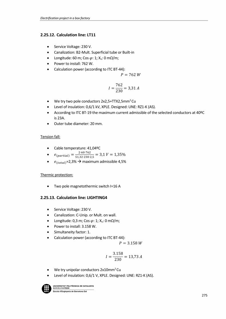
Electrification project in a box factory
275
2.25.12. Calculation line: LT11
Service Voltage: 230 V.
Canalization: B2-Mult. Superficial tube or Built-in
Longitude: 60 m; Cos 𝜑: 1; Xu: 0 mΩ/m;
Power to install: 762 W.
Calculation power (according to ITC BT-44):
𝑃 = 762 𝑊
𝐼 =762
230= 3,31 𝐴
We try two pole conductors 2x2,5+TTX2,5mm2 Cu
Level of insulation: 0,6/1 kV, XPLE. Designed: UNE: RZ1-K (AS).
According to ITC BT-19 the maximum current admissible of the selected conductors at 40ºC
is 23A.
Outer tube diameter: 20 mm.
Tension fall:
Cable temperature: 41,04ºC
𝑒(𝑝𝑎𝑟𝑡𝑖𝑎𝑙) =2·60·762
51,32·230·2,5= 3,1 𝑉 = 1,35%
𝑒(𝑡𝑜𝑡𝑎𝑙)=2,3% maximum admissible 4,5%
Thermic protection:
Two pole magnetothermic switch I=16 A
2.25.13. Calculation line: LIGHTING4
Service Voltage: 230 V.
Canalization: C-Unip. or Mult. on wall.
Longitude: 0,3 m; Cos 𝜑: 1; Xu: 0 mΩ/m;
Power to install: 3.158 W.
Simultaneity factor: 1.
Calculation power (according to ITC BT-44):
𝑃 = 3.158 𝑊
𝐼 =3.158
230= 13,73 𝐴
We try unipolar conductors 2x10mm2 Cu
Level of insulation: 0,6/1 V, XPLE. Designed: UNE: RZ1-K (AS).

Memoria
276
According to ITC BT-19 the maximum current admissible of the selected conductors at 40ºC
is 54 A.
Tension fall:
Cable temperature: 41,94ºC
𝑒(𝑝𝑎𝑟𝑡𝑖𝑎𝑙) =2·0,3·3.158
51,16·230·10= 0,02𝑉 = 0,01%
𝑒(𝑡𝑜𝑡𝑎𝑙)=0,96% maximum admissible 4,5%
Differential protection:
Two pole differential switch I=63 A. Sens. I=30 mA. AC class.
2.25.14. Calculation line: LT07
Service Voltage: 230 V.
Canalization: B2-Mult. Superficial tube or Built-in
Longitude: 50 m; Cos 𝜑: 1; Xu: 0 mΩ/m;
Power to install: 1.504 W.
Calculation power (according to ITC BT-44):
𝑃 = 1.504 𝑊
𝐼 =1.504
230= 6,54 𝐴
We try two pole conductors 2x2,5+TTX2,5mm2 Cu
Level of insulation: 0,6/1 kV, XPLE. Designed: UNE: RZ1-K (AS).
According to ITC BT-19 the maximum current admissible of the selected conductors at 40ºC
is 23A.
Outer tube diameter: 20 mm.
Tension fall:
Cable temperature: 44,04ºC
𝑒(𝑝𝑎𝑟𝑡𝑖𝑎𝑙) =2·50·1.504
50,77·230·2,5= 5,15 𝑉 = 2,24%
𝑒(𝑡𝑜𝑡𝑎𝑙)=3,2% maximum admissible 4,5%
Thermic protection:
Two pole magnetothermic switch I=16 A

Electrification project in a box factory
277
2.25.15. Calculation line: LT09
Service Voltage: 230 V.
Canalization: B2-Mult. Superficial tube or Built-in
Longitude: 50 m; Cos 𝜑: 1; Xu: 0 mΩ/m;
Power to install: 1.504 W.
Calculation power (according to ITC BT-44):
𝑃 = 1.504 𝑊
𝐼 =1.504
230= 6,54 𝐴
We try two pole conductors 2x2,5+TTX2,5mm2 Cu
Level of insulation: 0,6/1 kV, XPLE. Designed: UNE: RZ1-K (AS).
According to ITC BT-19 the maximum current admissible of the selected conductors at 40ºC
is 23A.
Outer tube diameter: 20 mm.
Tension fall:
Cable temperature: 44,04ºC
𝑒(𝑝𝑎𝑟𝑡𝑖𝑎𝑙) =2·50·1.504
50,77·230·2,5= 5,15 𝑉 = 2,24%
𝑒(𝑡𝑜𝑡𝑎𝑙)=3,2% maximum admissible 4,5%
Thermic protection:
Two pole magnetothermic switch I=16 A
2.25.16. Calculation line: EMERGENCY02
Service Voltage: 230 V.
Canalization: B2-Mult. Superficial tube or Built-in
Longitude: 60 m; Cos 𝜑: 1; Xu: 0 mΩ/m;
Power to install: 150 W.
Calculation power (according to ITC BT-44):
𝑃 = 150 𝑊
𝐼 =150
230= 0,65 𝐴
We try two pole conductors 2x1,5+TTx1,5mm2 Cu
Level of insulation: 0,6/1 kV, XPLE. Designed: UNE: RZ1-K (AS).
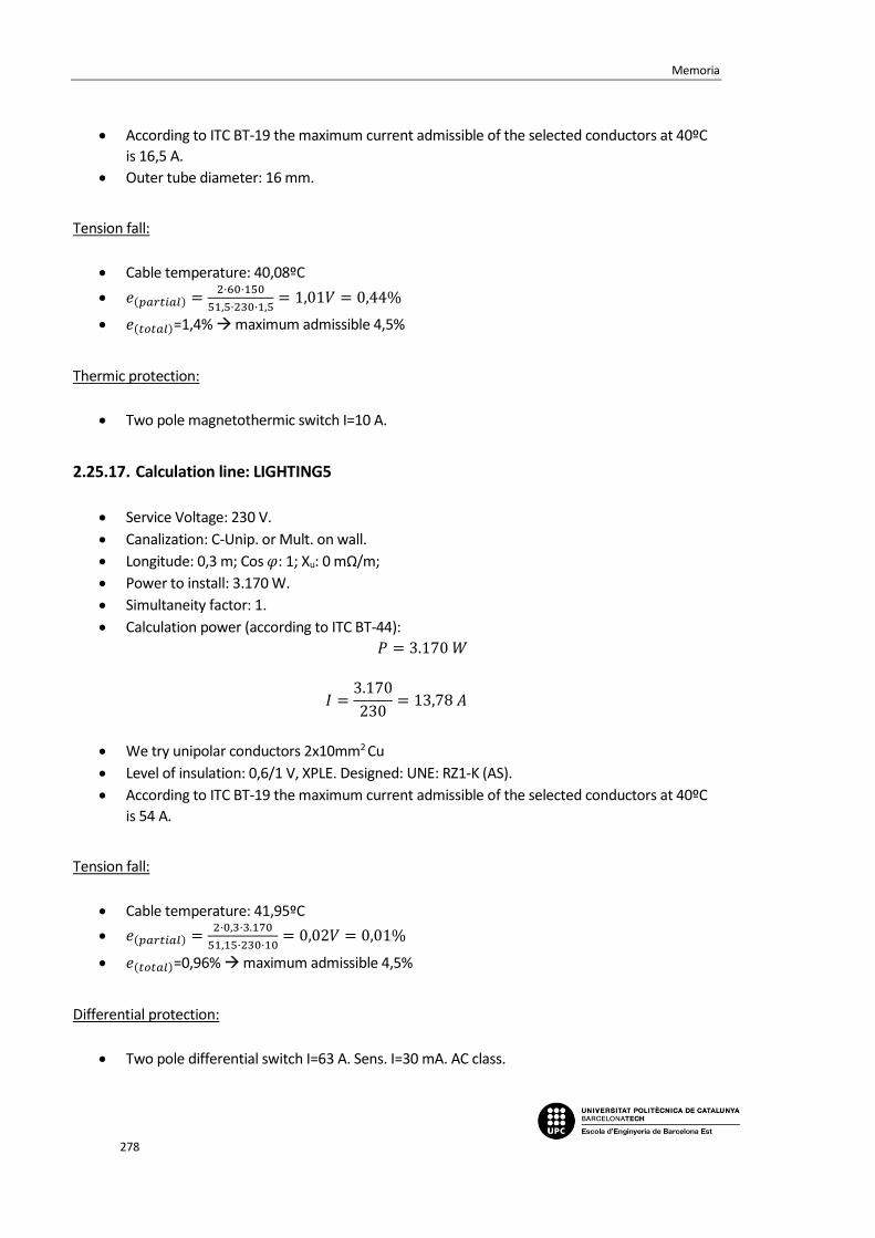
Memoria
278
According to ITC BT-19 the maximum current admissible of the selected conductors at 40ºC
is 16,5 A.
Outer tube diameter: 16 mm.
Tension fall:
Cable temperature: 40,08ºC
𝑒(𝑝𝑎𝑟𝑡𝑖𝑎𝑙) =2·60·150
51,5·230·1,5= 1,01𝑉 = 0,44%
𝑒(𝑡𝑜𝑡𝑎𝑙)=1,4% maximum admissible 4,5%
Thermic protection:
Two pole magnetothermic switch I=10 A.
2.25.17. Calculation line: LIGHTING5
Service Voltage: 230 V.
Canalization: C-Unip. or Mult. on wall.
Longitude: 0,3 m; Cos 𝜑: 1; Xu: 0 mΩ/m;
Power to install: 3.170 W.
Simultaneity factor: 1.
Calculation power (according to ITC BT-44):
𝑃 = 3.170 𝑊
𝐼 =3.170
230= 13,78 𝐴
We try unipolar conductors 2x10mm2 Cu
Level of insulation: 0,6/1 V, XPLE. Designed: UNE: RZ1-K (AS).
According to ITC BT-19 the maximum current admissible of the selected conductors at 40ºC
is 54 A.
Tension fall:
Cable temperature: 41,95ºC
𝑒(𝑝𝑎𝑟𝑡𝑖𝑎𝑙) =2·0,3·3.170
51,15·230·10= 0,02𝑉 = 0,01%
𝑒(𝑡𝑜𝑡𝑎𝑙)=0,96% maximum admissible 4,5%
Differential protection:
Two pole differential switch I=63 A. Sens. I=30 mA. AC class.
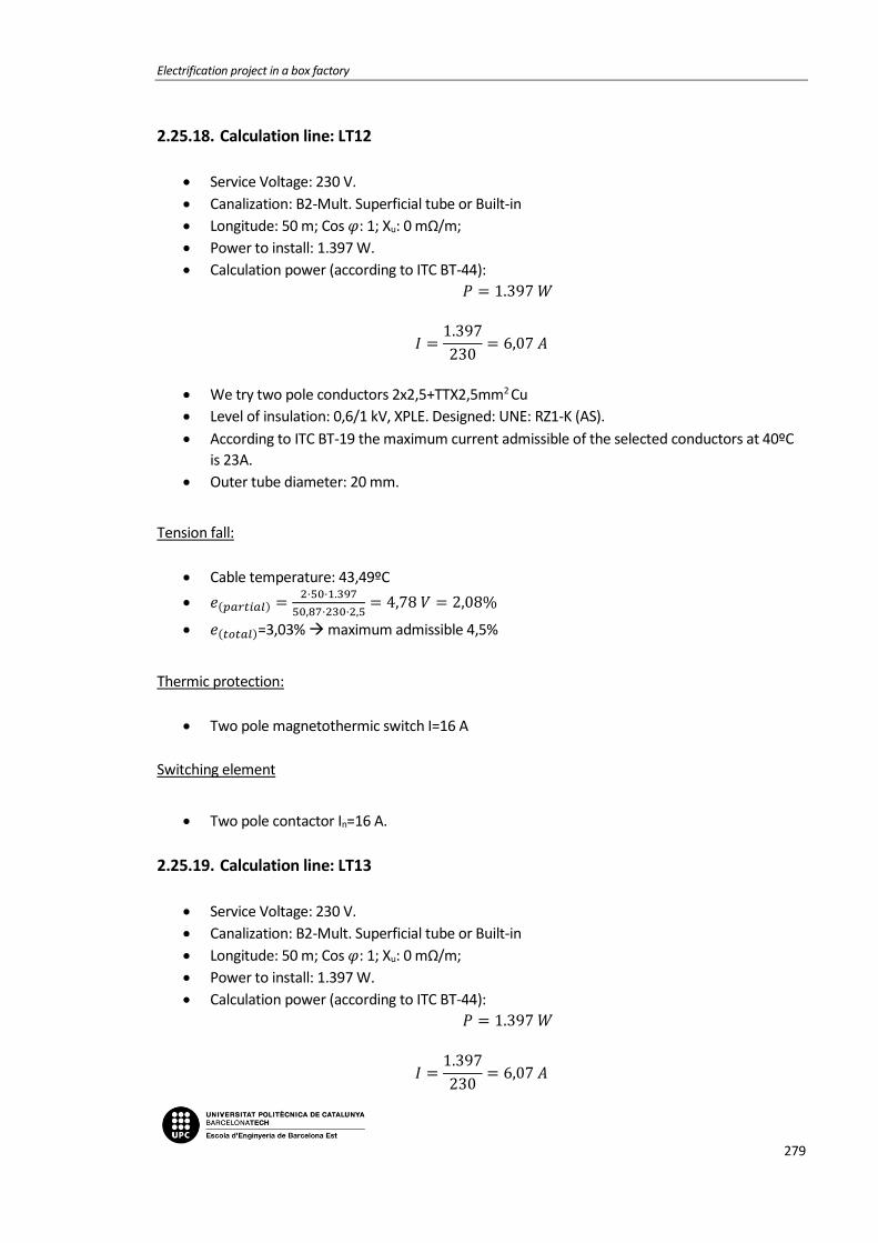
Electrification project in a box factory
279
2.25.18. Calculation line: LT12
Service Voltage: 230 V.
Canalization: B2-Mult. Superficial tube or Built-in
Longitude: 50 m; Cos 𝜑: 1; Xu: 0 mΩ/m;
Power to install: 1.397 W.
Calculation power (according to ITC BT-44):
𝑃 = 1.397 𝑊
𝐼 =1.397
230= 6,07 𝐴
We try two pole conductors 2x2,5+TTX2,5mm2 Cu
Level of insulation: 0,6/1 kV, XPLE. Designed: UNE: RZ1-K (AS).
According to ITC BT-19 the maximum current admissible of the selected conductors at 40ºC
is 23A.
Outer tube diameter: 20 mm.
Tension fall:
Cable temperature: 43,49ºC
𝑒(𝑝𝑎𝑟𝑡𝑖𝑎𝑙) =2·50·1.397
50,87·230·2,5= 4,78 𝑉 = 2,08%
𝑒(𝑡𝑜𝑡𝑎𝑙)=3,03% maximum admissible 4,5%
Thermic protection:
Two pole magnetothermic switch I=16 A
Switching element
Two pole contactor In=16 A.
2.25.19. Calculation line: LT13
Service Voltage: 230 V.
Canalization: B2-Mult. Superficial tube or Built-in
Longitude: 50 m; Cos 𝜑: 1; Xu: 0 mΩ/m;
Power to install: 1.397 W.
Calculation power (according to ITC BT-44):
𝑃 = 1.397 𝑊
𝐼 =1.397
230= 6,07 𝐴

Memoria
280
We try two pole conductors 2x2,5+TTX2,5mm2 Cu
Level of insulation: 0,6/1 kV, XPLE. Designed: UNE: RZ1-K (AS).
According to ITC BT-19 the maximum current admissible of the selected conductors at 40ºC
is 23A.
Outer tube diameter: 20 mm.
Tension fall:
Cable temperature: 43,49ºC
𝑒(𝑝𝑎𝑟𝑡𝑖𝑎𝑙) =2·50·1.397
50,87·230·2,5= 4,78 𝑉 = 2,08%
𝑒(𝑡𝑜𝑡𝑎𝑙)=3,03% maximum admissible 4,5%
Thermic protection:
Two pole magnetothermic switch I=16 A
Switching element
Two pole contactor In=16 A.
2.25.20. Calculation line: LT14
Service Voltage: 230 V.
Canalization: B2-Mult. Superficial tube or Built-in.
Longitude: 80 m; Cos 𝜑: 1; Xu: 0 mΩ/m;
Power to install: 376 W.
Calculation power (according to ITC BT-44):
𝑃 = 376 𝑊
𝐼 =376
230= 1,63 𝐴
We try two pole conductors 2x6+TTX6mm2 Cu
Level of insulation: 0,6/1 kV, XPLE. Designed: UNE: RZ1-K (AS).
According to ITC BT-19 the maximum current admissible of the selected conductors at 40ºC
is 53A.
Outer tube diameter: 50 mm.
Tension fall:
Cable temperature: 40,05ºC
𝑒(𝑝𝑎𝑟𝑡𝑖𝑎𝑙) =2·80·376
51,51·230·6= 0,85 𝑉 = 0,37%

Electrification project in a box factory
281
𝑒(𝑡𝑜𝑡𝑎𝑙)=1,32% maximum admissible 4,5%
Thermic protection:
Two pole magnetothermic switch I=16 A.
Switching element
Two pole contactor In=16 A.
2.25.21. Calculation line: LIGHTING6
Service Voltage: 230 V.
Canalization: C-Unip. or Mult. on wall.
Longitude: 0,3 m; Cos 𝜑: 1; Xu: 0 mΩ/m;
Power to install: 2.256 W.
Simultaneity factor: 1.
Calculation power (according to ITC BT-44):
𝑃 = 2.256 𝑊
𝐼 =2.256
230= 12,26 𝐴
We try unipolar conductors 2x6mm2 Cu
Level of insulation: 0,6/1 V, XPLE. Designed: UNE: RZ1-K (AS).
According to ITC BT-19 the maximum current admissible of the selected conductors at 40ºC
is 40 A.
Tension fall:
Cable temperature: 42,82ºC
𝑒(𝑝𝑎𝑟𝑡𝑖𝑎𝑙) =2·0,3·2.256
50,99·230·6= 0,02𝑉 = 0,01%
𝑒(𝑡𝑜𝑡𝑎𝑙)=0,96% maximum admissible 4,5%
Differential protection:
Two pole differential switch I=40 A. Sens. I=30 mA. AC class.
2.25.22. Calculation line: LT08
Service Voltage: 230 V.
Canalization: B2-Mult. Superficial tube or Built-in

Memoria
282
Longitude: 50 m; Cos 𝜑: 1; Xu: 0 mΩ/m;
Power to install: 1.504 W.
Calculation power (according to ITC BT-44):
𝑃 = 1.504 𝑊
𝐼 =1.504
230= 6,54 𝐴
We try two pole conductors 2x2,5+TTX2,5mm2 Cu
Level of insulation: 0,6/1 kV, XPLE. Designed: UNE: RZ1-K (AS).
According to ITC BT-19 the maximum current admissible of the selected conductors at 40ºC
is 23A.
Outer tube diameter: 20 mm.
Tension fall:
Cable temperature: 44,04ºC
𝑒(𝑝𝑎𝑟𝑡𝑖𝑎𝑙) =2·50·1.504
50,77·230·2,5= 5,15 𝑉 = 2,24%
𝑒(𝑡𝑜𝑡𝑎𝑙)=3,2% maximum admissible 4,5%
Thermic protection:
Two pole magnetothermic switch I=16 A
2.25.23. Calculation line: LT10
Service Voltage: 230 V.
Canalization: B1-Unip. Superficial tube or Built-in.
Longitude: 40 m; Cos 𝜑: 1; Xu: 0 mΩ/m;
Power to install: 752 W.
Calculation power (according to ITC BT-44):
𝑃 = 752 𝑊
𝐼 =752
230= 3,27 𝐴
We try unipolar conductors 2x2,5+TTX2,5mm2 Cu
Level of insulation: 0,6/1 kV, XPLE. Designed: UNE: RZ1-K (AS).
According to ITC BT-19 the maximum current admissible of the selected conductors at 40ºC
is 21A.
Outer tube diameter: 20 mm.
Tension fall:

Electrification project in a box factory
283
Cable temperature: 40,73ºC
𝑒(𝑝𝑎𝑟𝑡𝑖𝑎𝑙) =2·40·752
51,38·230·2,5= 2,04 𝑉 = 0,89%
𝑒(𝑡𝑜𝑡𝑎𝑙)=1,84% maximum admissible 4,5%
Thermic protection:
Two pole magnetothermic switch I=16 A
2.25.24. Calculation line: DALI
Service Voltage: 230 V.
Canalization: B1-Unip. Superficial tube or Built-in.
Longitude: 10 m; Cos 𝜑: 1; Xu: 0 mΩ/m;
Power to install: 2.000 W.
Calculation power: 𝑃 = 2.000 𝑊
𝐼 =2.000
230= 10,87 𝐴
We try unipolar conductors 2x2,5+TTX2,5mm2 Cu
Level of insulation: 0,6/1 kV, XPLE. Designed: UNE: RZ1-K (AS).
According to ITC BT-19 the maximum current admissible of the selected conductors at 40ºC
is 21A.
Outer tube diameter: 20 mm.
Tension fall:
Cable temperature: 48,04ºC
𝑒(𝑝𝑎𝑟𝑡𝑖𝑎𝑙) =2·10·2.000
50,05·230·2,5= 1,39 𝑉 = 0,6%
𝑒(𝑡𝑜𝑡𝑎𝑙)=1,55% maximum admissible 6,5%
Thermic protection:
Two pole magnetothermic switch I=16 A
Differential protection:
Two pole differential switch I=25 A. Sens. I=30 mA. AC class.

Memoria
284
2.25.25. Bus Bar calculations: SP-LIGHTING
Data
Metal: Cu.
State of the plates: Bare.
Number of plates per phase: 1.
Distance between plates: d=10 cm.
Distance between supports: L=25 cm.
Short circuit time: 0,5 s.
Used plate
Section: 24 mm2.
Amplitude: 12 mm.
Thickness: 2 mm.
Wx, Ix, Wi, li (cm3, cm4): 0,048 ; 0,0288 ; 0,008; 0,0008.
I. admissible of the bus bar: 110 A.
a) Electrodynamic calculation
𝜎𝑚𝑎𝑥 =2,1
2 · 252
60 · 10 · 0,008 · 1= 573,26 ≤ 1200
𝑘𝑔
𝑐𝑚2 𝐶𝑢
b) Thermal calculation per admissible current
𝐼𝑐𝑎𝑙 = 14,21 𝐴
𝐼𝑎𝑑𝑚 = 110 𝐴
c) Check for thermal request in short circuit
𝐼𝑝𝑐𝑐 = 2,1 𝑘𝐴
𝐼𝑐𝑐𝑐𝑠 =𝐾𝑐 · 𝑆
1000 · √𝑡𝑐𝑐
=164 · 24
1000 · √0,5= 5,57 𝑘𝐴
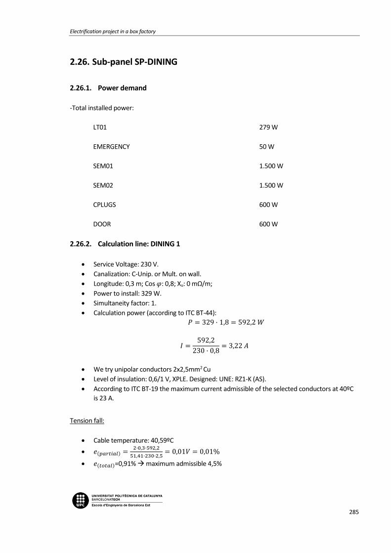
Electrification project in a box factory
285
2.26. Sub-panel SP-DINING
2.26.1. Power demand
-Total installed power:
LT01 279 W
EMERGENCY 50 W
SEM01 1.500 W
SEM02 1.500 W
CPLUGS 600 W
DOOR 600 W
2.26.2. Calculation line: DINING 1
Service Voltage: 230 V.
Canalization: C-Unip. or Mult. on wall.
Longitude: 0,3 m; Cos 𝜑: 0,8; Xu: 0 mΩ/m;
Power to install: 329 W.
Simultaneity factor: 1.
Calculation power (according to ITC BT-44):
𝑃 = 329 · 1,8 = 592,2 𝑊
𝐼 =592,2
230 · 0,8= 3,22 𝐴
We try unipolar conductors 2x2,5mm2 Cu
Level of insulation: 0,6/1 V, XPLE. Designed: UNE: RZ1-K (AS).
According to ITC BT-19 the maximum current admissible of the selected conductors at 40ºC
is 23 A.
Tension fall:
Cable temperature: 40,59ºC
𝑒(𝑝𝑎𝑟𝑡𝑖𝑎𝑙) =2·0,3·592,2
51,41·230·2,5= 0,01𝑉 = 0,01%
𝑒(𝑡𝑜𝑡𝑎𝑙)=0,91% maximum admissible 4,5%

Memoria
286
Differential protection:
Two pole differential switch I=25 A. Sens. I=30 mA. AC class.
2.26.3. Calculation line: LT01
Service Voltage: 230 V.
Canalization: B1-Unip. Superficial tube or Built-in.
Longitude: 15 m; Cos 𝜑: 1; Xu: 0 mΩ/m;
Power to install: 279 W.
Calculation power (according to ITC BT-44):
𝑃 = 279 · 1,8 = 502,2 𝑊
𝐼 =502,2
230= 2,18 𝐴
We try unipolar conductors 2x1,5+TTx1,5mm2 Cu
Level of insulation: 0,6/1 V, XPLE. Designed: UNE: RZ1-K (AS).
According to ITC BT-19 the maximum current admissible of the selected conductors at 40ºC
is 15A.
Outer tube diameter: 16 mm.
Tension fall:
Cable temperature: 40,64ºC
𝑒(𝑝𝑎𝑟𝑡𝑖𝑎𝑙) =2·15·502,2
51,4·230·1,5= 0,85 𝑉 = 0,37%
𝑒(𝑡𝑜𝑡𝑎𝑙)=1,28% maximum admissible 4,5%
Thermic protection:
Two pole magnetothermic switch I=10 A
2.26.4. Calculation line: EMERGENCY
Service Voltage: 230 V.
Canalization: B1-Unip. tube superf. or Built-in.
Longitude: 15 m; Cos 𝜑: 1; Xu: 0 mΩ/m;
Power to install: 50 W.
Calculation power (according to ITC BT-44):
𝑃 = 50 · 1,8 = 90 𝑊

Electrification project in a box factory
287
𝐼 =90
230= 0,39 𝐴
We try unipolar conductors 2x1,5+TTx1,5mm2 Cu
Level of insulation: 0,6/1 V, XPLE. Designed: UNE: RZ1-K (AS).
According to ITC BT-19 the maximum current admissible of the selected conductors at 40ºC
is 15 A.
Outer tube diameter: 16 mm.
Tension fall:
Cable temperature: 40,02ºC
𝑒(𝑝𝑎𝑟𝑡𝑖𝑎𝑙) =2·15·90
51,51·230·1,5= 0,15𝑉 = 0,07%
𝑒(𝑡𝑜𝑡𝑎𝑙)=0,98% maximum admissible 4,5%
Thermic protection:
Two pole magnetothermic switch I=10 A.
2.26.5. Calculation line: DINING 2
Service Voltage: 230 V.
Canalization: C-Unip. or Mult. on wall.
Longitude: 0,3 m; Cos 𝜑: 0,8; Xu: 0 mΩ/m;
Power to install: 3.000 W.
Simultaneity factor: 1.
Calculation power (according to ITC BT-44):
𝑃 = 3.000 𝑊
𝐼 =3.000
230 · 0,8= 16,3 𝐴
We try unipolar conductors 2x2,5mm2 Cu
Level of insulation: 0,6/1 V, XPLE. Designed: UNE: RZ1-K (AS).
According to ITC BT-19 the maximum current admissible of the selected conductors at 40ºC
is 23 A.
Tension fall:
Cable temperature: 55,8ºC
𝑒(𝑝𝑎𝑟𝑡𝑖𝑎𝑙) =2·0,3·3.000
48,84·230·2,5= 0,06𝑉 = 0,03%

Memoria
288
𝑒(𝑡𝑜𝑡𝑎𝑙)=0,93% maximum admissible 4,5%
Differential protection:
Two pole differential switch I=40 A. Sens. I=30 mA. AC class.
2.26.6. Calculation line: SEM01
Service Voltage: 230 V.
Canalization: B1-Unip. Superficial tube or Built-in.
Longitude: 15 m; Cos 𝜑: 0,8; Xu: 0 mΩ/m;
Power to install: 1.500 W.
Calculation power: 1.500 W
𝐼 =1.500
230 · 0,8= 8,15 𝐴
We try unipolar conductors 2x2,5+TTx2,5mm2 Cu
Level of insulation: 0,6/1 V, XPLE. Designed: UNE: RZ1-K (AS).
According to ITC BT-19 the maximum current admissible of the selected conductors at 40ºC
is 21A.
Outer tube diameter: 20 mm.
Tension fall:
Cable temperature: 44,52ºC
𝑒(𝑝𝑎𝑟𝑡𝑖𝑎𝑙) =2·15·1.500
50,68·230·2,5= 1,54 𝑉 = 0,67%
𝑒(𝑡𝑜𝑡𝑎𝑙)=1,6% maximum admissible 6,5%
Thermic protection:
Two pole magnetothermic switch I=16 A
2.26.7. Calculation line: SEM02
Service Voltage: 230 V.
Canalization: B1-Unip. Superficial tube or Built-in.
Longitude: 15 m; Cos 𝜑: 0,8; Xu: 0 mΩ/m;
Power to install: 1.500 W.
Calculation power: 1.500 W
𝐼 =1.500
230 · 0,8= 8,15 𝐴
We try unipolar conductors 2x2,5+TTx2,5mm2 Cu
Level of insulation: 0,6/1 V, XPLE. Designed: UNE: RZ1-K (AS).

Electrification project in a box factory
289
According to ITC BT-19 the maximum current admissible of the selected conductors at 40ºC
is 21A.
Outer tube diameter: 20 mm.
Tension fall:
Cable temperature: 44,52ºC
𝑒(𝑝𝑎𝑟𝑡𝑖𝑎𝑙) =2·15·1.500
50,68·230·2,5= 1,54 𝑉 = 0,67%
𝑒(𝑡𝑜𝑡𝑎𝑙)=1,6% maximum admissible 6,5%
Thermic protection:
Two pole magnetothermic switch I=16 A
2.26.8. Calculation line: CPLUGS
Service Voltage: 230 V.
Canalization: B1-Unip. Superficial tube or Built-in.
Longitude: 25 m; Cos 𝜑: 0,8; Xu: 0 mΩ/m;
Power to install: 600 W.
Calculation power: 600 W
𝐼 =600
230 · 0,8= 3,26 𝐴
We try unipolar conductors 2x2,5+TTx2,5mm2 Cu
Level of insulation: 0,6/1 V, XPLE. Designed: UNE: RZ1-K (AS).
According to ITC BT-19 the maximum current admissible of the selected conductors at 40ºC
is 21A.
Outer tube diameter: 20 mm.
Tension fall:
Cable temperature: 40,72ºC
𝑒(𝑝𝑎𝑟𝑡𝑖𝑎𝑙) =2·25·600
51,38·230·2,5= 1,02 𝑉 = 0,44%
𝑒(𝑡𝑜𝑡𝑎𝑙)=1,35% maximum admissible 6,5%
Thermic protection:
Two pole magnetothermic switch I=16 A
Differential protection:
Two pole differential switch I=25 A. Sens. I=30 mA. AC class.

Memoria
290
2.26.9. Calculation line: DOOR
Service Voltage: 230 V.
Canalization: B1-Unip. Superficial tube or Built-in.
Longitude: 15 m; Cos 𝜑: 0,8; Xu: 0 mΩ/m; R:1;
Power to install: 600 W.
Calculation power (according to ITC BT-47):
𝑃 = 600 · 1,25 = 750 𝑊
𝐼 =750
230 · 0,8= 4,08 𝐴
We try unipolar conductors 2x2,5+TTx2,5mm2 Cu
Level of insulation: 0,6/1 V, XPLE. Designed: UNE: RZ1-K (AS).
According to ITC BT-19 the maximum current admissible of the selected conductors at 40ºC
is 21A.
Outer tube diameter: 20 mm.
Tension fall:
Cable temperature: 41,13ºC
𝑒(𝑝𝑎𝑟𝑡𝑖𝑎𝑙) =2·15·750
51,31·230·2,5= 0,76 𝑉 = 0,33%
𝑒(𝑡𝑜𝑡𝑎𝑙)=1,24% maximum admissible 6,5%
Thermic protection:
Two pole magnetothermic switch I=16 A
Differential protection:
Two pole differential switch I=25 A. Sens. I=30 mA. AC class.
2.26.10. Bus Bar calculations: SP-DINING
Data
Metal: Cu.
State of the plates: Bare.
Number of plates per phase: 1.
Distance between plates: d=10 cm.
Distance between supports: L=25 cm.
Short circuit time: 0,5 s.
Used plate

Electrification project in a box factory
291
Section: 24 mm2.
Amplitude: 12 mm.
Thickness: 2 mm.
Wx, Ix, Wi, li (cm3, cm4): 0,048 ; 0,0288 ; 0,008; 0,0008.
I. admissible of the bus bar: 110 A.
a) Electrodynamic calculation
𝜎𝑚𝑎𝑥 =0,62
2 · 252
60 · 10 · 0,008 · 1= 50,768 ≤ 1200
𝑘𝑔
𝑐𝑚2 𝐶𝑢
b) Thermal calculation per admissible current
𝐼𝑐𝑎𝑙 = 4,59 𝐴
𝐼𝑎𝑑𝑚 = 110 𝐴
c) Check for thermal request in short circuit
𝐼𝑝𝑐𝑐 = 0,62 𝑘𝐴
𝐼𝑐𝑐𝑐𝑠 =𝐾𝑐 · 𝑆
1000 · √𝑡𝑐𝑐
=164 · 24
1000 · √0,5= 5,57 𝑘𝐴
2.27. Sub-panel SP-DYE
2.27.1. Power demand
-Total installed power:
DISP01 300 W
AGI01 750 W
COM01 2.400 W
AIR01 1.500 W
LIFT01 367 W
AGI02 367 W
SERBOX 2.000 W

Memoria
292
LT01 863 W
LT02 863 W
LT03 863 W
EMERGENCY 50 W
2.27.2. Calculation line: DYE 1
Service Voltage: 400 V.
Canalization: C-Unip. or Mult. on wall.
Longitude: 0,3 m; Cos 𝜑: 0,8; Xu: 0 mΩ/m;
Power to install: 1.050 W.
Simultaneity factor: 1.
Calculation power (according to ITC BT-47):
𝑃 = 750 · 1,25 + 300 = 1.237,5 𝑊
𝐼 =1.237,5
0,8 · 400 · √3= 2,23 𝐴
We try unipolar conductors 4x6mm2 Cu
Level of insulation: 0,6/1 V, XPLE. Designed: UNE: RZ1-K (AS).
According to ITC BT-19 the maximum current admissible of the selected conductors at 40ºC
is 36 A.
Tension fall:
Cable temperature: 40,12ºC
𝑒(𝑝𝑎𝑟𝑡𝑖𝑎𝑙) =0,3·1.237,5
51,51·400·6= 0 𝑉 = 0%
𝑒(𝑡𝑜𝑡𝑎𝑙)=1,4% maximum admissible 4,5%
Differential protection:
Four pole differential switch I=40 A. Sens. I=30 mA. AC class.
2.27.3. Calculation line: DISP01
Service Voltage: 400 V.
Canalization: B1-Unip. Superficial tube or Built-in.
Longitude: 15 m; Cos 𝜑: 0,8; Xu: 0 mΩ/m; R: 1;
Electrification project in a box factory
293
Power to install: 300 W.
Calculation power (according to ITC BT-47):
𝑃 = 300 · 1,25 = 375 𝑊
𝐼 =375
0,8 · 400 · √3 · 1= 0,68 𝐴
We try unipolar conductors 4x2,5+TTx2,5mm2 Cu
Level of insulation: 0,6/1 kV, XPLE. Designed: UNE: RZ1-K (AS).
According to ITC BT-19 the maximum current admissible of the selected conductors at 40ºC
is 18,5A.
Outer tube diameter: 20 mm.
Tension fall:
Cable temperature: 40,04ºC
𝑒(𝑝𝑎𝑟𝑡𝑖𝑎𝑙) =15·375
51,51·400·2,5= 0,11 𝑉 = 0,03%
𝑒(𝑡𝑜𝑡𝑎𝑙)=1,43% maximum admissible 6,5%
Thermic protection:
Four pole magnetothermic switch I=16 A.
2.27.4. Calculation line: AGI01
Service Voltage: 400 V.
Canalization: B1-Unip. Superficial tube or Built-in.
Longitude: 15 m; Cos 𝜑: 0,8; Xu: 0 mΩ/m; R: 1;
Power to install: 750 W.
Calculation power (according to ITC BT-47):
𝑃 = 750 · 1,25 = 937,5 𝑊
𝐼 =937,5
0,8 · 400 · √3 · 1= 1,69 𝐴
We try unipolar conductors 4x2,5+TTx2,5mm2 Cu
Level of insulation: 0,6/1 kV, XPLE. Designed: UNE: RZ1-K (AS).
According to ITC BT-19 the maximum current admissible of the selected conductors at 40ºC
is 18,5A.
Outer tube diameter: 20 mm.
Tension fall:
Memoria
294
Cable temperature: 40,25ºC
𝑒(𝑝𝑎𝑟𝑡𝑖𝑎𝑙) =15·937,5
51,47·400·2,5= 0,27 𝑉 = 0,07%
𝑒(𝑡𝑜𝑡𝑎𝑙)=1,47% maximum admissible 6,5%
Thermic protection:
Four pole magnetothermic switch I=16 A.
2.27.5. Calculation line: COM01
Service Voltage: 400 V.
Canalization: B1-Unip. Superficial tube or Built-in.
Longitude: 15 m; Cos 𝜑: 0,8; Xu: 0 mΩ/m; R: 1;
Power to install: 2.400 W.
Calculation power (according to ITC BT-47):
𝑃 = 2.400 · 1,25 = 3.000 𝑊
𝐼 =3.000
0,8 · 400 · √3 · 1= 5,41 𝐴
We try unipolar conductors 4x2,5+TTx2,5mm2 Cu
Level of insulation: 0,6/1 kV, XPLE. Designed: UNE: RZ1-K (AS).
According to ITC BT-19 the maximum current admissible of the selected conductors at 40ºC
is 18,5A.
Outer tube diameter: 20 mm.
Tension fall:
Cable temperature: 42,57ºC
𝑒(𝑝𝑎𝑟𝑡𝑖𝑎𝑙) =15·3.000
51,04·400·2,5= 0,88 𝑉 = 0,22%
𝑒(𝑡𝑜𝑡𝑎𝑙)=1,62% maximum admissible 6,5%
Thermic protection:
Four pole magnetothermic switch I=16 A.
Differential protection:
Four pole differential switch I=25 A. Sens. I=30 mA. AC class.

Electrification project in a box factory
295
2.27.6. Calculation line: DYE 2
Service Voltage: 400 V.
Canalization: C-Unip. or Mult. on wall.
Longitude: 0,3 m; Cos 𝜑: 0,8; Xu: 0 mΩ/m;
Power to install: 2.234 W.
Simultaneity factor: 1.
Calculation power (according to ITC BT-47):
𝑃 = 1.500 · 1,25 + 734 = 2.609 𝑊
𝐼 =2.609
0,8 · 400 · √3= 4,71 𝐴
We try unipolar conductors 4x10mm2 Cu
Level of insulation: 0,6/1 V, XPLE. Designed: UNE: RZ1-K (AS).
According to ITC BT-19 the maximum current admissible of the selected conductors at 40ºC
is 50 A.
Tension fall:
Cable temperature: 40,27ºC
𝑒(𝑝𝑎𝑟𝑡𝑖𝑎𝑙) =0,3·2.609
51,47·400·10= 0 𝑉 = 0%
𝑒(𝑡𝑜𝑡𝑎𝑙)=1,4% maximum admissible 4,5%
Differential protection:
Four pole differential switch I=40 A. Sens. I=30 mA. AC class.
2.27.7. Calculation line: AIR01
Service Voltage: 400 V.
Canalization: B1-Unip. Superficial tube or Built-in.
Longitude: 15 m; Cos 𝜑: 0,8; Xu: 0 mΩ/m; R: 1;
Power to install: 1.500 W.
Calculation power (according to ITC BT-47):
𝑃 = 1.500 · 1,25 = 1.875 𝑊
𝐼 =1.875
0,8 · 400 · √3 · 1= 3,38 𝐴
We try unipolar conductors 4x2,5+TTx2,5mm2 Cu

Memoria
296
Level of insulation: 0,6/1 kV, XPLE. Designed: UNE: RZ1-K (AS).
According to ITC BT-19 the maximum current admissible of the selected conductors at 40ºC
is 18,5A.
Outer tube diameter: 20 mm.
Tension fall:
Cable temperature: 41ºC
𝑒(𝑝𝑎𝑟𝑡𝑖𝑎𝑙) =15·1.875
51,33·400·2,5= 0,55 𝑉 = 0,14%
𝑒(𝑡𝑜𝑡𝑎𝑙)=1,54% maximum admissible 6,5%
Thermic protection:
Four pole magnetothermic switch I=16 A.
2.27.8. Calculation line: LIFT01
Service Voltage: 400 V.
Canalization: B1-Unip. Superficial tube or Built-in.
Longitude: 20 m; Cos 𝜑: 0,8; Xu: 0 mΩ/m;
Power to install: 367 W.
Calculation power:367 𝑊
𝐼 =367
0,8 · 400 · √3= 0,66 𝐴
We try unipolar conductors 4x2,5+TTx2,5mm2 Cu
Level of insulation: 0,6/1 kV, XPLE. Designed: UNE: RZ1-K (AS).
According to ITC BT-19 the maximum current admissible of the selected conductors at 40ºC
is 18,5A.
Outer tube diameter: 20 mm.
Tension fall:
Cable temperature: 40,04ºC
𝑒(𝑝𝑎𝑟𝑡𝑖𝑎𝑙) =20·367
51,51·400·2,5= 0,14 𝑉 = 0,04%
𝑒(𝑡𝑜𝑡𝑎𝑙)=1,44% maximum admissible 6,5%
Thermic protection:
Four pole magnetothermic switch I=16 A.

Electrification project in a box factory
297
2.27.9. Calculation line: AGI02
Service Voltage: 400 V.
Canalization: B1-Unip. Superficial tube or Built-in.
Longitude: 15 m; Cos 𝜑: 0,8; Xu: 0 mΩ/m;
Power to install: 367 W.
Calculation power:367 𝑊
𝐼 =367
0,8 · 400 · √3= 0,66 𝐴
We try unipolar conductors 4x2,5+TTx2,5mm2 Cu
Level of insulation: 0,6/1 kV, XPLE. Designed: UNE: RZ1-K (AS).
According to ITC BT-19 the maximum current admissible of the selected conductors at 40ºC
is 18,5A.
Outer tube diameter: 20 mm.
Tension fall:
Cable temperature: 40,04ºC
𝑒(𝑝𝑎𝑟𝑡𝑖𝑎𝑙) =15·367
51,51·400·2,5= 0,11 𝑉 = 0,03%
𝑒(𝑡𝑜𝑡𝑎𝑙)=1,44% maximum admissible 6,5%
Thermic protection:
Four pole magnetothermic switch I=16 A.
2.27.10. Calculation line: SERBOX
Service Voltage: 400 V.
Canalization: B1-Unip. Superficial tube or Built-in.
Longitude: 20 m; Cos 𝜑: 0,8; Xu: 0 mΩ/m;
Power to install: 2.000 W.
Calculation power:2.000 𝑊
𝐼 =2.000
0,8 · 400 · √3= 3,61 𝐴
We try unipolar conductors 4x10+TTx10mm2 Cu
Level of insulation: 0,6/1 kV, XPLE. Designed: UNE: RZ1-K (AS).
According to ITC BT-19 the maximum current admissible of the selected conductors at 40ºC
is 44A.

Memoria
298
Outer tube diameter: 32 mm.
Tension fall:
Cable temperature: 40,2ºC
𝑒(𝑝𝑎𝑟𝑡𝑖𝑎𝑙) =20·2.000
51,48·400·10= 0,19 𝑉 = 0,05%
𝑒(𝑡𝑜𝑡𝑎𝑙)=1,45% maximum admissible 6,5%
Thermic protection:
Four pole magnetothermic switch I=40 A.
Differential protection:
Four pole differential switch I=40 A. Sens. I=30 mA. AC class.
2.27.11. Calculation line: DYE 3
Service Voltage: 230 V.
Canalization: C-Unip. or Mult. on wall.
Longitude: 0,3 m; Cos 𝜑: 0,8; Xu: 0 mΩ/m;
Power to install: 2.639 W.
Simultaneity factor: 1.
Calculation power (according to ITC BT-44):
𝑃 = 2.679 𝑊
𝐼 =2.679
230 · 0,8= 14,56𝐴
We try unipolar conductors 2x6mm2 Cu
Level of insulation: 0,6/1 V, XPLE. Designed: UNE: RZ1-K (AS).
According to ITC BT-19 the maximum current admissible of the selected conductors at 40ºC
is 40 A.
Tension fall:
Cable temperature: 43,97ºC
𝑒(𝑝𝑎𝑟𝑡𝑖𝑎𝑙) =2·0,3·2.679
50,78·230·6= 0,02𝑉 = 0,01%
𝑒(𝑡𝑜𝑡𝑎𝑙)=1,41% maximum admissible 4,5%
Differential protection:

Electrification project in a box factory
299
Two pole differential switch I=40 A. Sens. I=30 mA. AC class.
2.27.12. Calculation line: LT01
Service Voltage: 230 V.
Canalization: B1-Unip. tube superf. or Built-in.
Longitude: 15 m; Cos 𝜑: 1; Xu: 0 mΩ/m;
Power to install: 863 W.
Calculation power (according to ITC BT-44):
𝑃 = 863 𝑊
𝐼 =863
230= 3,75 𝐴
We try unipolar conductors 2x1,5+TTx1,5mm2 Cu
Level of insulation: 0,6/1 V, XPLE. Designed: UNE: RZ1-K (AS).
According to ITC BT-19 the maximum current admissible of the selected conductors at 40ºC
is 15 A.
Outer tube diameter: 16 mm.
Tension fall:
Cable temperature: 41,88ºC
𝑒(𝑝𝑎𝑟𝑡𝑖𝑎𝑙) =2·15·863
51,17·230·1,5= 1,47𝑉 = 0,64%
𝑒(𝑡𝑜𝑡𝑎𝑙)=2,05% maximum admissible 4,5%
Thermic protection:
Two pole magnetothermic switch I=10 A.
2.27.13. Calculation line: LT02
Service Voltage: 230 V.
Canalization: B1-Unip. tube superf. or Built-in.
Longitude: 20 m; Cos 𝜑: 1; Xu: 0 mΩ/m;
Power to install: 863 W.
Calculation power (according to ITC BT-44):
𝑃 = 863 𝑊

Memoria
300
𝐼 =863
230= 3,75 𝐴
We try unipolar conductors 2x1,5+TTx1,5mm2 Cu
Level of insulation: 0,6/1 V, XPLE. Designed: UNE: RZ1-K (AS).
According to ITC BT-19 the maximum current admissible of the selected conductors at 40ºC
is 15 A.
Outer tube diameter: 16 mm.
Tension fall:
Cable temperature: 41,88ºC
𝑒(𝑝𝑎𝑟𝑡𝑖𝑎𝑙) =2·20·863
51,17·230·1,5= 1,96𝑉 = 0,85%
𝑒(𝑡𝑜𝑡𝑎𝑙)=2,26% maximum admissible 4,5%
Thermic protection:
Two pole magnetothermic switch I=10 A.
2.27.14. Calculation line: LT03
Service Voltage: 230 V.
Canalization: B1-Unip. tube superf. or Built-in.
Longitude: 20 m; Cos 𝜑: 1; Xu: 0 mΩ/m;
Power to install: 863 W.
Calculation power (according to ITC BT-44):
𝑃 = 863 𝑊
𝐼 =863
230= 3,75 𝐴
We try unipolar conductors 2x1,5+TTx1,5mm2 Cu
Level of insulation: 0,6/1 V, XPLE. Designed: UNE: RZ1-K (AS).
According to ITC BT-19 the maximum current admissible of the selected conductors at 40ºC
is 15 A.
Outer tube diameter: 16 mm.
Tension fall:
Cable temperature: 41,88ºC

Electrification project in a box factory
301
𝑒(𝑝𝑎𝑟𝑡𝑖𝑎𝑙) =2·20·863
51,17·230·1,5= 1,96𝑉 = 0,85%
𝑒(𝑡𝑜𝑡𝑎𝑙)=2,26% maximum admissible 4,5%
Thermic protection:
Two pole magnetothermic switch I=10 A.
2.27.15. Calculation line: EMERGENCY
Service Voltage: 230 V.
Canalization: B1-Unip. tube superf. or Built-in.
Longitude: 20 m; Cos 𝜑: 1; Xu: 0 mΩ/m;
Power to install: 50 W.
Calculation power (according to ITC BT-44):
𝑃 = 50 · 1,8 = 90 𝑊
𝐼 =90
230= 0,39 𝐴
We try unipolar conductors 2x1,5+TTx1,5mm2 Cu
Level of insulation: 0,6/1 V, XPLE. Designed: UNE: RZ1-K (AS).
According to ITC BT-19 the maximum current admissible of the selected conductors at 40ºC
is 15 A.
Outer tube diameter: 16 mm.
Tension fall:
Cable temperature: 40,02ºC
𝑒(𝑝𝑎𝑟𝑡𝑖𝑎𝑙) =2·20·90
51,51·230·1,5= 0,2𝑉 = 0,09%
𝑒(𝑡𝑜𝑡𝑎𝑙)=1,5% maximum admissible 4,5%
Thermic protection:
Two pole magnetothermic switch I=10 A.
2.27.16. Bus Bar calculations: SP-DYE
Data
Metal: Cu.

Memoria
302
State of the plates: Bare.
Number of plates per phase: 1.
Distance between plates: d=10 cm.
Distance between supports: L=25 cm.
Short circuit time: 0,5 s.
Used plate
Section: 24 mm2.
Amplitude: 12 mm.
Thickness: 2 mm.
Wx, Ix, Wi, li (cm3, cm4): 0,048 ; 0,0288 ; 0,008; 0,0008.
I. admissible of the bus bar: 110 A.
a) Electrodynamic calculation
𝜎𝑚𝑎𝑥 =0,62
2 · 252
60 · 10 · 0,008 · 1= 50,768 ≤ 1200
𝑘𝑔
𝑐𝑚2 𝐶𝑢
b) Thermal calculation per admissible current
𝐼𝑐𝑎𝑙 = 10,43 𝐴
𝐼𝑎𝑑𝑚 = 110 𝐴
c) Check for thermal request in short circuit
𝐼𝑝𝑐𝑐 = 0,62 𝑘𝐴
𝐼𝑐𝑐𝑐𝑠 =𝐾𝑐 · 𝑆
1000 · √𝑡𝑐𝑐
=164 · 24
1000 · √0,5= 5,57 𝑘𝐴
2.28. GROUNDING CALCULATION
We consider that the land resistance is 300 Ωxm.
The electrode selected for the grounding are copper spades. It will be 10 spades around the
building. A naked copper conductor will join them all together to from an equipotential
bonding ring.
The spikes depth will be 2 meters.
Electrification project in a box factory
303
To measure the ground resistance, is used the ground breaking box, that separates the spikes
and the protection conductors.
The protection conductors have been calculated according to ITC-BT-18.
𝑅𝑔 =1
𝐿𝑐2 · 𝜌 +
𝐿𝑝
𝜌 +𝑃
0,8 · 𝜌
=1
1002 · 300 +
20300
= 4,28 Ω


Electrification project in a box factory
305