Embed Size (px)
Citation preview
2402 OPTICS LETTERS / Vol. 31, No. 16 / August 15, 2006
Electro-optic fiber sensor for amplitude and phasedetection of radio frequency electromagnetic
fields
Axel Kramer, Peter Müller, Urs Lott, and Niels KusterFoundation for Research on Information Technologies in Society (IT’IS), ETH Zentrum, ETZ, 8092 Zurich,
Switzerland
Fin BomholtSchmid & Partner Engineering AG, Zeughausstrasse 43, 8004 Zurich, Switzerland
Received February 16, 2006; revised May 17, 2006; accepted May 19, 2006;posted June 2, 2006 (Doc. ID 68184); published July 25, 2006
We present a miniature fiber-optic electromagnetic field (EMF) sensor that is capable of simultaneously de-tecting the amplitude and phase of an EMF in the range of 0.1–6 GHz. We focus on magnetic field mea-surements, since the H-field is more significant in our target applications due its direct relation to the cur-rent. The sensor is based on an open optical platform to which various antennas can be attached andcontains a radio-frequency amplifier for signal conditioning and a vertical-cavity surface-emitting laser asan electro-optic converter. The millimeter size and the full electrical isolation of the sensor allow EMF de-tection with minimal disturbance. We have characterized the sensor in the near field of a � /2 dipole, a rect-angular waveguide, and a microstrip line, and we explain the experimental results with a simple theoreticalmodel confirming the mapped near-field distribution of the investigated field source. © 2006 Optical Societyof America
OCIS codes: 060.0060, 120.0280.
The availability of low-cost analog radio frequencyand GHz digital technologies enables new productsthat provide a wireless connection, intelligent sen-sors, and new possibilities for medical diagnosis andtherapy. These applications will boost new demandsfor electromagnetic radio-frequency (RF) tools, inparticular electromagnetic field (EMF) sensors thatprovide simultaneous amplitude and phase detection,high spatial resolution, and minimal field perturba-tion. Traditional nondisturbing EMF probes, cur-rently used for analyzing various electromagneticproblems, are based on highly resistive lines, andtherefore are limited to measuring only the field am-plitude without phase information.1 Probes usingfast electrical links between the sensor and the read-out unit cause undesirable field distortions. However,sensors based on optical remote sensing can elimi-nate such influence.2–6 Various approaches for high-bandwidth optical link sensors based on differenttechnologies have been proposed, such as electroab-sorption sensors,3 Mach–Zehnder interferometersbased on the Pockels effect,4,5 and sensors using ac-tive modulation of a LED or a laser diode.2,6–8
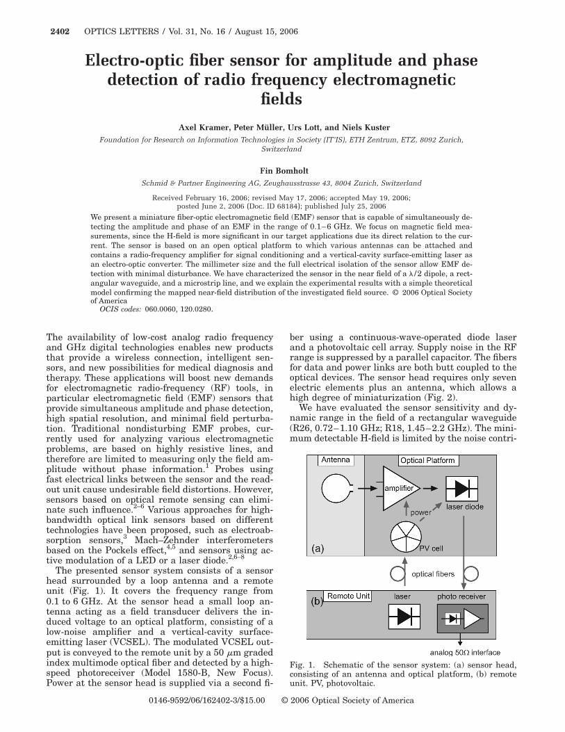
The presented sensor system consists of a sensorhead surrounded by a loop antenna and a remoteunit (Fig. 1). It covers the frequency range from0.1 to 6 GHz. At the sensor head a small loop an-tenna acting as a field transducer delivers the in-duced voltage to an optical platform, consisting of alow-noise amplifier and a vertical-cavity surface-emitting laser (VCSEL). The modulated VCSEL out-put is conveyed to the remote unit by a 50 �m gradedindex multimode optical fiber and detected by a high-speed photoreceiver (Model 1580-B, New Focus).
Power at the sensor head is supplied via a second fi-0146-9592/06/162402-3/$15.00 ©
ber using a continuous-wave-operated diode laserand a photovoltaic cell array. Supply noise in the RFrange is suppressed by a parallel capacitor. The fibersfor data and power links are both butt coupled to theoptical devices. The sensor head requires only sevenelectric elements plus an antenna, which allows ahigh degree of miniaturization (Fig. 2).
We have evaluated the sensor sensitivity and dy-namic range in the field of a rectangular waveguide(R26, 0.72–1.10 GHz; R18, 1.45–2.2 GHz). The mini-mum detectable H-field is limited by the noise contri-
Fig. 1. Schematic of the sensor system: (a) sensor head,consisting of an antenna and optical platform, (b) remote
unit. PV, photovoltaic.2006 Optical Society of America
August 15, 2006 / Vol. 31, No. 16 / OPTICS LETTERS 2403
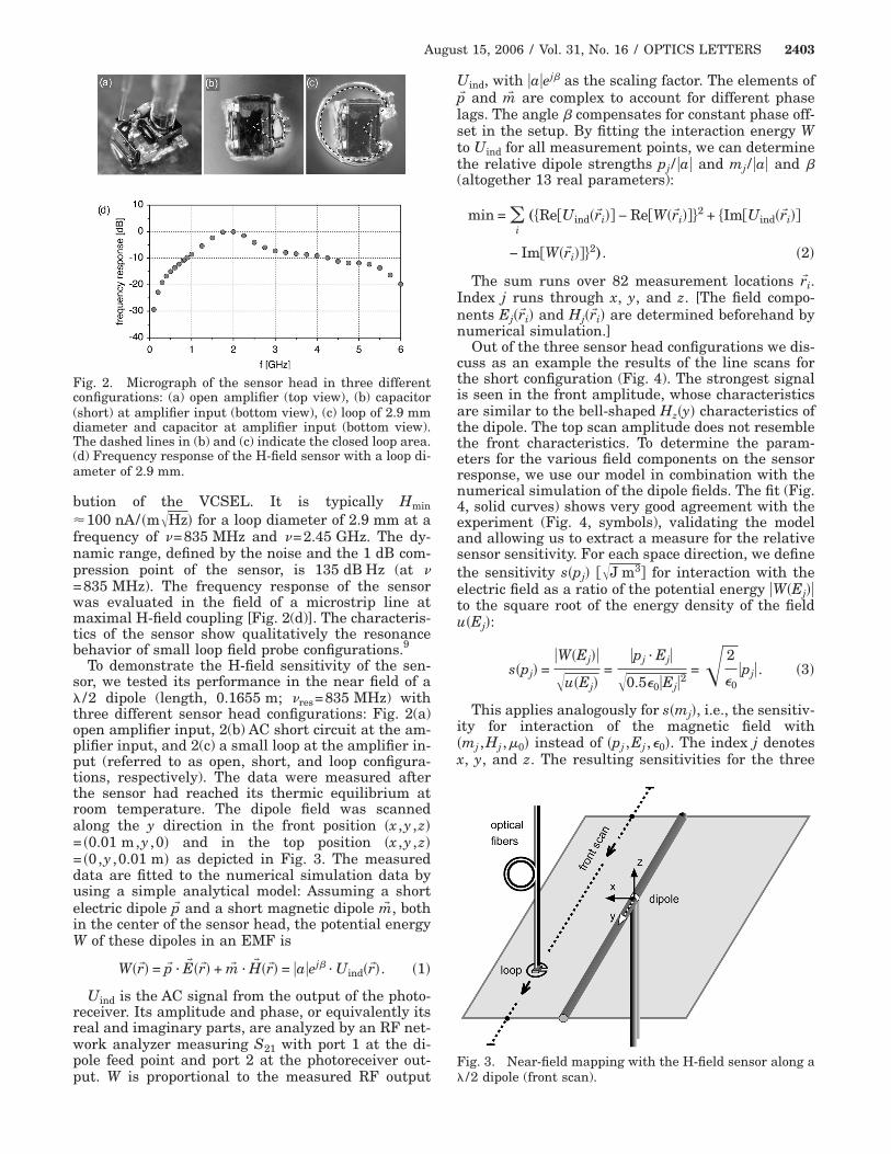
bution of the VCSEL. It is typically Hmin�100 nA/ �m�Hz� for a loop diameter of 2.9 mm at afrequency of �=835 MHz and �=2.45 GHz. The dy-namic range, defined by the noise and the 1 dB com-pression point of the sensor, is 135 dB Hz (at �=835 MHz). The frequency response of the sensorwas evaluated in the field of a microstrip line atmaximal H-field coupling [Fig. 2(d)]. The characteris-tics of the sensor show qualitatively the resonancebehavior of small loop field probe configurations.9
To demonstrate the H-field sensitivity of the sen-sor, we tested its performance in the near field of a� /2 dipole (length, 0.1655 m; �res=835 MHz) withthree different sensor head configurations: Fig. 2(a)open amplifier input, 2(b) AC short circuit at the am-plifier input, and 2(c) a small loop at the amplifier in-put (referred to as open, short, and loop configura-tions, respectively). The data were measured afterthe sensor had reached its thermic equilibrium atroom temperature. The dipole field was scannedalong the y direction in the front position �x ,y ,z�= �0.01 m,y ,0� and in the top position �x ,y ,z�= �0,y ,0.01 m� as depicted in Fig. 3. The measureddata are fitted to the numerical simulation data byusing a simple analytical model: Assuming a shortelectric dipole p� and a short magnetic dipole m� , bothin the center of the sensor head, the potential energyW of these dipoles in an EMF is
W�r�� = p� · E� �r�� + m� · H� �r�� = �a�ej� · Uind�r��. �1�
Uind is the AC signal from the output of the photo-receiver. Its amplitude and phase, or equivalently itsreal and imaginary parts, are analyzed by an RF net-work analyzer measuring S21 with port 1 at the di-pole feed point and port 2 at the photoreceiver out-
Fig. 2. Micrograph of the sensor head in three differentconfigurations: (a) open amplifier (top view), (b) capacitor(short) at amplifier input (bottom view), (c) loop of 2.9 mmdiameter and capacitor at amplifier input (bottom view).The dashed lines in (b) and (c) indicate the closed loop area.(d) Frequency response of the H-field sensor with a loop di-ameter of 2.9 mm.
put. W is proportional to the measured RF output
Uind, with �a�ej� as the scaling factor. The elements ofp� and m� are complex to account for different phaselags. The angle � compensates for constant phase off-set in the setup. By fitting the interaction energy Wto Uind for all measurement points, we can determinethe relative dipole strengths pj / �a� and mj / �a� and �(altogether 13 real parameters):
min = �i„�Re�Uind�r�i� − Re�W�r�i�2 + �Im�Uind�r�i�
− Im�W�r�i�2…. �2�
The sum runs over 82 measurement locations r�i.Index j runs through x, y, and z. [The field compo-nents Ej�r�i� and Hj�r�i� are determined beforehand bynumerical simulation.]
Out of the three sensor head configurations we dis-cuss as an example the results of the line scans forthe short configuration (Fig. 4). The strongest signalis seen in the front amplitude, whose characteristicsare similar to the bell-shaped Hz�y� characteristics ofthe dipole. The top scan amplitude does not resemblethe front characteristics. To determine the param-eters for the various field components on the sensorresponse, we use our model in combination with thenumerical simulation of the dipole fields. The fit (Fig.4, solid curves) shows very good agreement with theexperiment (Fig. 4, symbols), validating the modeland allowing us to extract a measure for the relativesensor sensitivity. For each space direction, we definethe sensitivity s�pj� ��J m3 for interaction with theelectric field as a ratio of the potential energy �W�Ej��to the square root of the energy density of the fieldu�Ej�:
s�pj� =�W�Ej��
�u�Ej�=
�pj · Ej�
�0.5�0�Ej�2=� 2
�0�pj�. �3�
This applies analogously for s�mj�, i.e., the sensitiv-ity for interaction of the magnetic field with�mj ,Hj ,�0� instead of �pj ,Ej ,�0�. The index j denotesx, y, and z. The resulting sensitivities for the three
Fig. 3. Near-field mapping with the H-field sensor along a
� /2 dipole (front scan).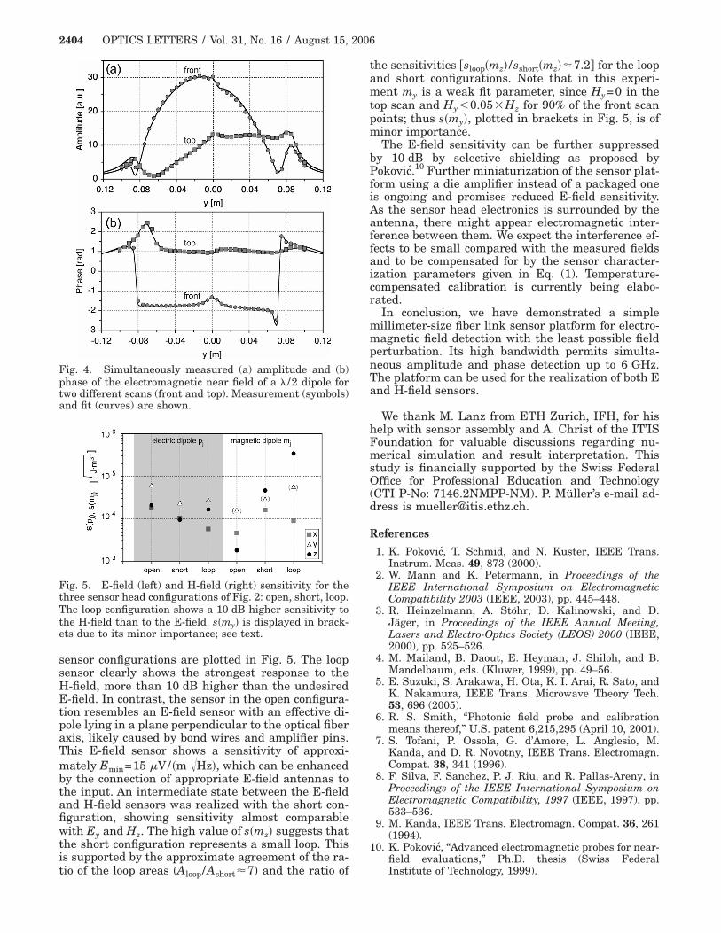
2404 OPTICS LETTERS / Vol. 31, No. 16 / August 15, 2006
sensor configurations are plotted in Fig. 5. The loopsensor clearly shows the strongest response to theH-field, more than 10 dB higher than the undesiredE-field. In contrast, the sensor in the open configura-tion resembles an E-field sensor with an effective di-pole lying in a plane perpendicular to the optical fiberaxis, likely caused by bond wires and amplifier pins.This E-field sensor shows a sensitivity of approxi-mately Emin=15 �V/ �m �Hz�, which can be enhancedby the connection of appropriate E-field antennas tothe input. An intermediate state between the E-fieldand H-field sensors was realized with the short con-figuration, showing sensitivity almost comparablewith Ey and Hz. The high value of s�mz� suggests thatthe short configuration represents a small loop. Thisis supported by the approximate agreement of the ra-
Fig. 4. Simultaneously measured (a) amplitude and (b)phase of the electromagnetic near field of a � /2 dipole fortwo different scans (front and top). Measurement (symbols)and fit (curves) are shown.
Fig. 5. E-field (left) and H-field (right) sensitivity for thethree sensor head configurations of Fig. 2: open, short, loop.The loop configuration shows a 10 dB higher sensitivity tothe H-field than to the E-field. s�my� is displayed in brack-ets due to its minor importance; see text.
tio of the loop areas �Aloop/Ashort�7� and the ratio of
the sensitivities �sloop�mz� /sshort�mz��7.2 for the loopand short configurations. Note that in this experi-ment my is a weak fit parameter, since Hy=0 in thetop scan and Hy�0.05�Hz for 90% of the front scanpoints; thus s�my�, plotted in brackets in Fig. 5, is ofminor importance.
The E-field sensitivity can be further suppressedby 10 dB by selective shielding as proposed byPokovic.10 Further miniaturization of the sensor plat-form using a die amplifier instead of a packaged oneis ongoing and promises reduced E-field sensitivity.As the sensor head electronics is surrounded by theantenna, there might appear electromagnetic inter-ference between them. We expect the interference ef-fects to be small compared with the measured fieldsand to be compensated for by the sensor character-ization parameters given in Eq. (1). Temperature-compensated calibration is currently being elabo-rated.
In conclusion, we have demonstrated a simplemillimeter-size fiber link sensor platform for electro-magnetic field detection with the least possible fieldperturbation. Its high bandwidth permits simulta-neous amplitude and phase detection up to 6 GHz.The platform can be used for the realization of both Eand H-field sensors.
We thank M. Lanz from ETH Zurich, IFH, for hishelp with sensor assembly and A. Christ of the IT’ISFoundation for valuable discussions regarding nu-merical simulation and result interpretation. Thisstudy is financially supported by the Swiss FederalOffice for Professional Education and Technology(CTI P-No: 7146.2NMPP-NM). P. Müller’s e-mail ad-dress is [email protected].
References
1. K. Pokovic, T. Schmid, and N. Kuster, IEEE Trans.Instrum. Meas. 49, 873 (2000).
2. W. Mann and K. Petermann, in Proceedings of theIEEE International Symposium on ElectromagneticCompatibility 2003 (IEEE, 2003), pp. 445–448.
3. R. Heinzelmann, A. Stöhr, D. Kalinowski, and D.Jäger, in Proceedings of the IEEE Annual Meeting,Lasers and Electro-Optics Society (LEOS) 2000 (IEEE,2000), pp. 525–526.
4. M. Mailand, B. Daout, E. Heyman, J. Shiloh, and B.Mandelbaum, eds. (Kluwer, 1999), pp. 49–56.
5. E. Suzuki, S. Arakawa, H. Ota, K. I. Arai, R. Sato, andK. Nakamura, IEEE Trans. Microwave Theory Tech.53, 696 (2005).
6. R. S. Smith, “Photonic field probe and calibrationmeans thereof,” U.S. patent 6,215,295 (April 10, 2001).
7. S. Tofani, P. Ossola, G. d’Amore, L. Anglesio, M.Kanda, and D. R. Novotny, IEEE Trans. Electromagn.Compat. 38, 341 (1996).
8. F. Silva, F. Sanchez, P. J. Riu, and R. Pallas-Areny, inProceedings of the IEEE International Symposium onElectromagnetic Compatibility, 1997 (IEEE, 1997), pp.533–536.
9. M. Kanda, IEEE Trans. Electromagn. Compat. 36, 261(1994).
10. K. Pokovic, “Advanced electromagnetic probes for near-field evaluations,” Ph.D. thesis (Swiss Federal
Institute of Technology, 1999).