Embed Size (px)
Citation preview

SUPPLEMENTARY INFORMATIONDOI: 10.1038/NPHOTON.2014.284
NATURE PHOTONICS | www.nature.com/naturephotonics 1
Electro-optics of Perovskite Solar Cells
Qianqian Lin, Ardalan Armin, Ravi Chandra Raju Nagiri, Paul L Burn* and PaulMeredith*
Centre for Organic Photonics & Electronics, School of Chemistry and MolecularBiosciences and School of Mathematics and Physics, The University of Queensland, StLucia Campus, Brisbane 4072 (Australia)
Email: [email protected]; [email protected]
Keywords: Perovskite solar cells, dielectric constant, optical constants, cavity optics
Supplementary information
Content:
1. Experimental details.
2. Supporting figures.
Electro-optics of perovskite solar cells
© 2014 Macmillan Publishers Limited. All rights reserved.

Materials: Lead iodide (PbI2, beads, 99.999% trace metals basis), methylamine (CH3NH2, 33 wt% in absolute ethanol) and hydroiodic acid (HI, 57 wt% in water) were purchased from Sigma-Aldrich. Poly(3,4-ethylenedioxythiophene):poly(styrene sulfonate) (PEDOT:PSS) was obtained from Heraeus (Clevios P Al4083). Poly[N-9''-heptadecanyl-2,7-carbazole-alt-5,5-(4',7'-di-2-thienyl-2',1',3'-benzothiadiazole)] (PCDTBT Mw = 122 kDa) was purchased from SJPC, Canada. Poly[2,6-(4,4-bis-(2-ethylhexyl)-4H-cyclopenta[2,1-b;3,4-b′]dithiophene)-alt-4,7(2,1,3-benzothiadiazole)] (PCPDTBT, Mw = 14 kDa) was purchased from Lumtec. Poly(N-alkyldiketopyrrolopyrrole dithienylthieno[3,2-b]thiophene) (DPP-DTT, Mw = 350 kDa) was synthesised by Institute of Materials Research and Engineering (IMRE), Singapores1. Poly(3-n-hexylthiophene) (P3HT, Mw = 52 kDa) was purchased from Merck. [6,6]-Phenyl-C61-butyric acid methyl ester (PC60BM) was purchased from ADS. All commercial products were used as received, unless other stated. Preparation of methylammonium iodide (MAI): MAI was prepared following the reported procedures2. Methylamine (20 mL, 33 wt% in absolute ethanol) was added to absolute ethanol (100 mL) that had been cooled under argon in an ice bath for 10 min. Stirring was continued for another 5 min and then hydroiodic acid solution (10 mL, 57 wt% in water) was added quickly. The resulting solution was stirred under argon for 3 h at 0~5 oC. The solvent was completely removed using a rotary evaporator. The crude product was then dissolved in absolute ethanol (20 mL) and precipitated by slowly adding diethyl ether (200 mL) with vigorous stirring. The precipitate was collected at the filter and washed with diethyl ether (3 × 50 mL) three times. The color of the product, MAI, changed from pale brown to yellow, and finally to white. The MAI was then dried at 60 °C under vacuum for 12 h to give MAI (9 g, 75%). The final product thus obtained was transferred to the glove box immediately to protect from degradation and hydration. All glassware was cleaned using freshly prepared pirahna solution (a mixture of concentrated sulfuric acid and hydrogen peroxide with a volume ratio of 3:1). Device fabrication: All the solar cells were fabricated in a class 1000 clean room on commercial indium tin oxide (ITO) patterned glass electrodes (15 Ω/sq, Kintec). All the electrodes were cleaned in an Alconox (detergent) solution bath at 70 °C, followed by sonication in sequence with Alconox, Milli-Q water, acetone and 2-propanol for 10 min each. The cleaned substrates were dried with a stream of nitrogen and before being coated with 15±5 nm PEDOT:PSS by spin-coating at 5000 rpm for 30 s. The PEDOT:PSS coated substrates were heated on a hot plate at 170 °C for 10 min. After thermal treatment the substrates were transferred into a nitrogen glove box for device fabrication (O2 <1 ppm, H2O <1 ppm). The temperature in the glove box was ~20 °C. The PEDOT:PSS coated substrates were heated inside the glovebox at 170 °C for another 10 min. After cooling, the polymer interlayers were spin-coated onto the substrates from solutions with a concentration of 1 mg/mL in dichlorobenzene at 1500 rpm for 40 s. All substrates were
© 2014 Macmillan Publishers Limited. All rights reserved.

allowed to dry under ambient conditions for 3 h before being heated at 70 °C for 10 min. CH3NH3PbI3 perovskite layers were then deposited via dual-source thermal evaporation (see below) to the desired film thickness. After depositing the perovskite layer, a 10 mg/mL PC60BM in toluene solution was spin-coated onto the CH3NH3PbI3 perovskite layer at a spin speed of 1000 rpm for 40 s. The devices were heated on a hot plate at 70 °C for 10 min. Finally, 1 nm LiF and 100 nm Ag were deposited by thermal evaporation under 10-6 mbar vacuum with an appropriate mask (0.2 cm2 for each device), which defined the cell area, to complete the device. There were 6 cells per substrate. Several representative high efficiency devices were encapsulated for long term stability measurements and to check the progression of any hysteresis in the J-V scans. A standard encapsulation protocol was used, namely: epoxy resin (XNR 5516Z-B1, Nagase ChemteX Corporation) was screened on the edges of a capping glass plate, which was then adhered onto the solar cells devices firmly before being illumination under UV light for 10 min. Dual-source evaporation: CH3NH3PbI3 perovskite films were deposited by dual-source evaporation. In a typical process, 500 mg of MAI and 300 mg PbI2 were heated in separate crucibles at different temperatures simultaneously. The evaporation rate was monitored using a quartz crystal microbalance (QCM) sensor positioned between the two sources and close to the substrate. The evaporation rates of both the sources were strongly temperature dependent and these rates dictated film quality. Various perovskite films were deposited at 10-5 mbar chamber pressure by evaporating MAI at a constant 100 °C and PbI2 at various temperatures in the range 250 °C to 280 °C. Increasing the PbI2 evaporation temperature from 250 °C to 280 °C resulted in the total evaporation rate varying from 0.3 Å/s to 1.1 Å/s.
© 2014 Macmillan Publishers Limited. All rights reserved.

400 500 600 700 800 900
650 700 750 800
Opt
ical
den
sity
(a. u
.)
Wavelength (nm)
PCDTBT DPP-DTT P3HT PCPDTBT
Opt
ical
den
sity
(a. u
.)Wavelength (nm)
Figure S1 Optical absorption characterisation of CH3NH3PbI3 perovskite/polymer bilayer films. Absorption spectra in the wavelength range 350 nm to 900 nm. The inset shows the sharpness of the optical gap of the perovskite films.
© 2014 Macmillan Publishers Limited. All rights reserved.
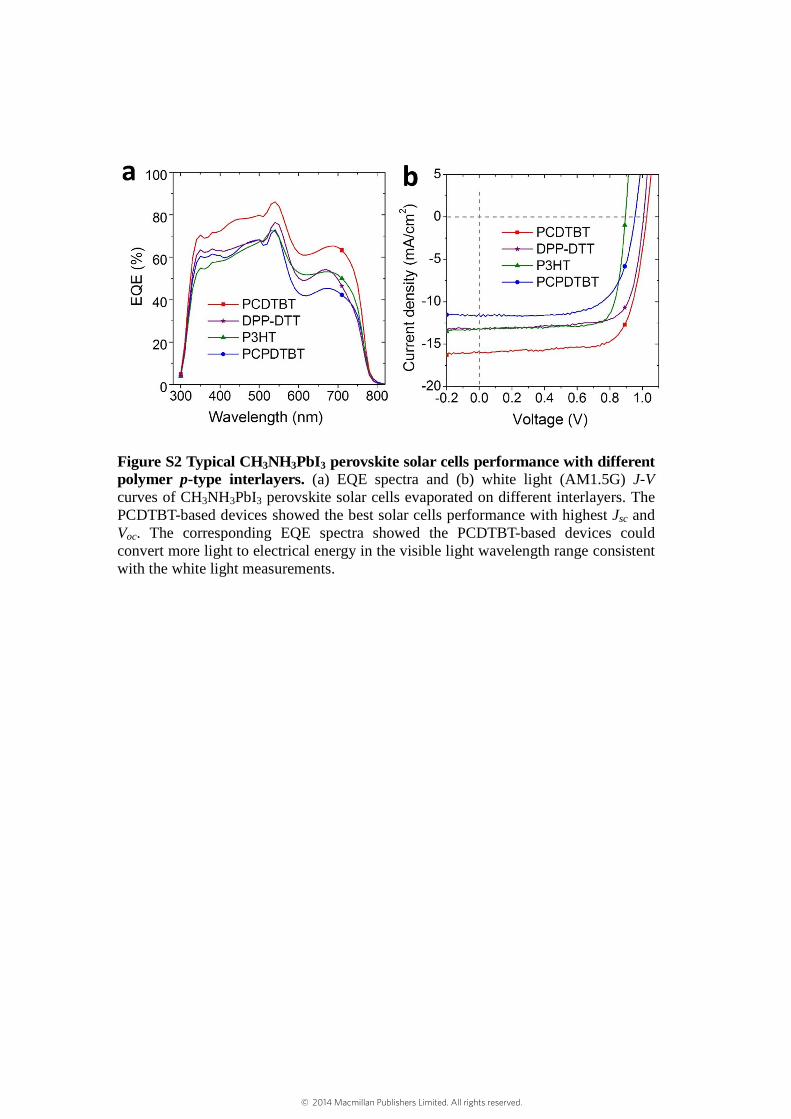
Figure S2 Typical CH3NH3PbI3 perovskite solar cells performance with different polymer p-type interlayers. (a) EQE spectra and (b) white light (AM1.5G) J-V curves of CH3NH3PbI3 perovskite solar cells evaporated on different interlayers. The PCDTBT-based devices showed the best solar cells performance with highest Jsc and Voc. The corresponding EQE spectra showed the PCDTBT-based devices could convert more light to electrical energy in the visible light wavelength range consistent with the white light measurements.
© 2014 Macmillan Publishers Limited. All rights reserved.

Table S1 Solar cells performance statistics of perovskite solar cells (6 devices each) prepared using different polymer p-type interlayers. *Data for the devices prepared using DPP-DTT as the interlayer have limited statistics as most were shorted due to poor film uniformity.
Jsc (mA/cm2) Voc (V) FF PCE (%) PCDTBT 15.9±0.7 1.03.±0.01 0.66±0.05 10.9±0.8
DPP-DTT* 13.3 1.00 0.74 9.8 P3HT 14.2±0.9 0.70±0.10 0.78±0.03 8.5±0.8
PCPDTBT 13.0±0.8 0.88±0.06 0.69±0.04 7.8±0.8
Figure S3 Scanning Electron Microscopy images of CH3NH3PbI3 perovskite film surfaces prepared under various thermal evaporation conditions (dual source evaporation temperatures). (a) MAI (100 °C), PbI2 (280 °C), (b) MAI (100 °C), PbI2 (260 °C), (c) MAI (100 °C), PbI2 (250 °C) and (d) a cross-sectional SEM image of a perovskite device prepared at MAI (100 °C), PbI2 (280 °C), showing ~520 nm thickness.
© 2014 Macmillan Publishers Limited. All rights reserved.

Figure S4 X-ray Diffraction (XRD) characteristics of perovskite films prepared at various PbI2 evaporation temperatures with fixed MAI temperature (100 °C). (a) XRD spectra showing the preferential orientation across the planes (110) and (220). The inset of the graph shows the signatures of PbI2 with the appearance of a peak at ~12.7°. (b) The (110) plane and (c) (220) planes are described by comparing the inter-planar distances with theoretical values calculated for the tetragonal crystal lattice parameters (a = b = 8.86 Å, c = 12.66 Å)s3.
© 2014 Macmillan Publishers Limited. All rights reserved.
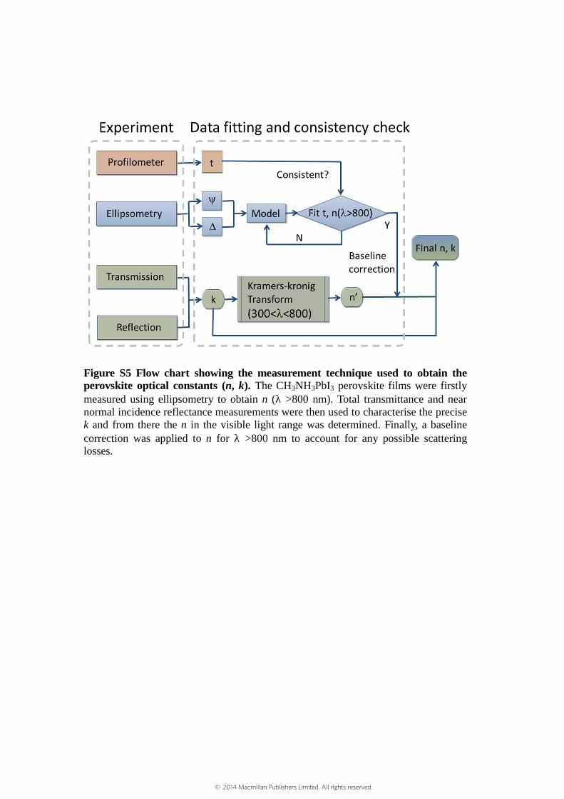
Figure S5 Flow chart showing the measurement technique used to obtain the perovskite optical constants (n, k). The CH3NH3PbI3 perovskite films were firstly measured using ellipsometry to obtain n (λ >800 nm). Total transmittance and near normal incidence reflectance measurements were then used to characterise the precise k and from there the n in the visible light range was determined. Finally, a baseline correction was applied to n for λ >800 nm to account for any possible scattering losses.
© 2014 Macmillan Publishers Limited. All rights reserved.

Figure S6 Static dielectric constant measured by Charge Extraction Under Linearly Increasing Voltage (CELIV). (a) By applying a triangle CELIV pulse to a perovskite diode with a structure representative of the optimised solar cell one can measure a photocurrent extraction transient where the displacement current (as marked in the figure) is directly proportional to the capacitance of the cell. The capacitance per area can be calculated as C = j0 / (dV/dt) = j0 / (Vmax/tp), where tp is the voltage pulse length. The dielectric constant is then obtained as = = 70. Full details of the technique and approach can be found in references4. (b) The same methodology used to obtain the static dielectric constant of a 600 µm thick device fabricated by pelletising perosvksite powder and with a diode structure of Au/perovskite/Au. In this latter case the dielectric constant was found to be 45 consistent with the lower density of the pellet relative to the evaporated thin film. The measurements of (a) and (b) were performed at a repetition rate of 1 Hz and showed no difference when compared with the single shot results.
© 2014 Macmillan Publishers Limited. All rights reserved.

Figure S7 Optical constants (n, k) for all the non-junction materials used in this paper. (a) Glass, (b) ITO, (c) PEDOT:PSS, (d) PCDTBT, (e) PC60BM and (f) Ag. All of the n and k values were measured via spectroscopic ellipsometry with the same materials used in the devices.
© 2014 Macmillan Publishers Limited. All rights reserved.
Figure S8 Electro-optic modeling of the maximum short circuit current (Jsc) as a a function of the interlayers and perovskite junction thicknesses. (a) PCDTBT and CH3NH3PbI3 layers varied, (b) PC60BM and CH3NH3PbI3 layers varied, (c) PCDTBT layer varied with fixed CH3NH3PbI3 layer thickness at 350 nm and (d) PC60BM layer varied with fixed CH3NH3PbI3 layer thickness at 350 nm. The modeled results show the thickness of PCDTBT affects the Jsc of the solar cells considerably. The PC60BM layer thickness does not have significant influence on the theoretical Jsc value. Calculations assume 100% IQE to translate the optical field distribution to extracted current.
© 2014 Macmillan Publishers Limited. All rights reserved.

Figure S9 Hysteresis of optimised CH3NH3PbI3 perovskite solar cells. Forward and back J-V scans of (a) as-prepared devices with scan rate of 0.1 V/s; and encapsulated devices after storing in air for more than 4 months with scan rates of (b) 0.05 V/s, (c) 0.1 V/s and (d) 0.2 V/s. There was no hysteresis observed in the as-prepared devices and encapsulated devices at any of the scan rates.
© 2014 Macmillan Publishers Limited. All rights reserved.

Figure S10 Long term stability of CH3NH3PbI3 perovskite solar cells. (a) Jsc, Voc and; (b) FF and PCE under 1 sun (100 mW/cm2) as a function of time. These devices were encapsulated between glass slides sealed with epoxy resin and stored in air for more than 4 months and tested more than 30 times. All were illuminated under 1 sun for more than 8 hours. The PCE decreased by ~ 10% after 4 months storage and numerous tests demonstrating respectable stability. Error bars represent multiple measurements and devices and the values are averages.
© 2014 Macmillan Publishers Limited. All rights reserved.

Figure S11 Light intensity dependent short circuit current density of an optimised CH3NH3PbI3 perovskite solar cell. The extracted current depends linearly on the input light intensity to beyond 1 sun (100 mW/cm2). This indicates minimal bimolecular recombination under normal operating conditions in this solar cell junction.
© 2014 Macmillan Publishers Limited. All rights reserved.
References s1. Li J. et al. A stable solution-processed polymer semiconductor with record high-mobility for
printed transistors. Sci. Rep. 2, 754 (2012). s2. Lee M. M., Teuscher J., Miyasaka T., Murakami T. N., Snaith H. J. Efficient hybrid solar cells
based on meso-superstructured organometal halide perovskites. Science 338, 643-647 (2012). s3. Mosconi E., Amat A., Nazeeruddin M. K., Gratzel M., De Angelis F. First-principles modeling of
mixed halide organometal perovskites for photovoltaic applications. J. Phys. Chem. C, 117, 13902-13913 (2013).
s4. Armin A. et al. Injected charge extraction by linearly increasing voltage for bimolecular
recombination studies in organic solar cells. Appl. Phys. Lett. 101, 083306 (2012).
© 2014 Macmillan Publishers Limited. All rights reserved.