Embed Size (px)
Citation preview

1
ELECTROCHEMICAL METHODS
2
Electroanalytical measurements have certain advantages over other types of chemical analysis.
The measurements are specific to the oxidation state of the element.
The instrumentation is relatively inexpensive as compared to spectrochemical methods.
They provide information about the activities of the ions chemical species rather than the concentrations.

3
ELECTROCHEMICAL CELLS
A Direct Current (DC) electrochemical cell consists oftwo electrical conductors called electrodes dipped in asuitable electrolyte solution. For current to develop in acell certain conditions need to be met.
The electrodes must be connected externally with a metal conductor.The two electrolyte solutions must be in contact with each other to permit the movement of ions from one to another preferably via a salt bridge.An electron-transfer reaction must occur at each of the two electrodes.

4
GALVANIC ELECTROCHEMICAL CELL

5
GALVANIC CELL DOING WORK
6
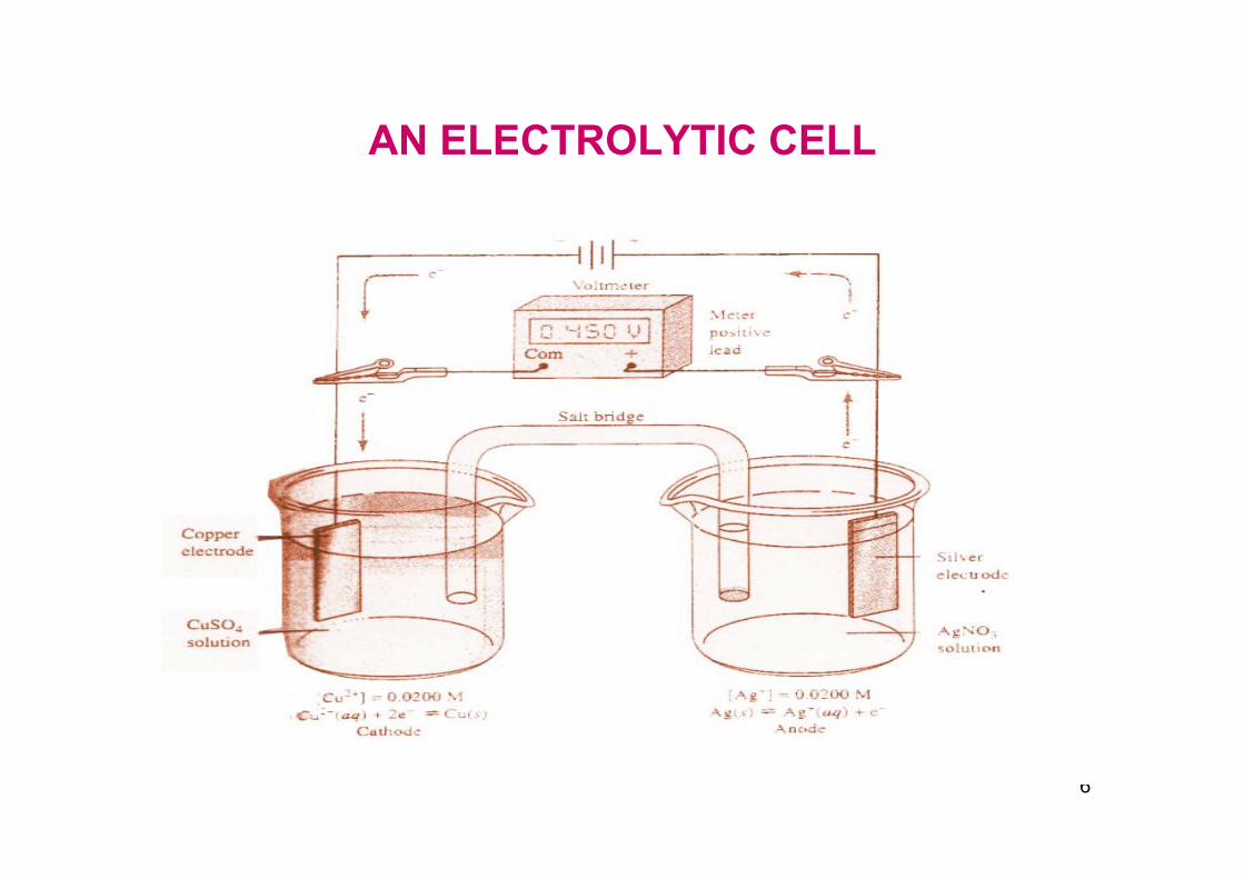
AN ELECTROLYTIC CELL

7
A salt bridge consists of a tube filled with a saturated solution of potassium chloride or nitrate boiled withgelatin to form a thick paste. The ends of the tube arefitted with porous plugs or discs that permit the movementof the ions across them but prevent draining or siphoningof the liquid from one to the other. The salt bridge isolatesthe two halves of the cell while maintaining the electricalcontact between them. Thus direct contact or reactionbetween the solutions is avoided.

8
At the interfaces between the electrolytes and the solid Electrodes, a small potential exists which is known asliquid junction potential. The liquid junction potential isan important concept in electrochemistry which
influences the accuracy of the analysis to a significant extent.
When both the electrodes are dipped in the same solution liquid junction does not exist.

9
If we replace the meter with a low resistance wire, the circuit is completed and charge flows. Three distinct phenomena take place under these conditions.
a) Copper ions migrate away from the electrode into the solution. Sulphate and hydrogen sulphate ions move toward the metal.
In the other beaker silver ions move from the solution toward the electrode and anions move away from it.
Inside the salt bridge charge is carried by potassium ions to the right and chloride ions to the left.
10
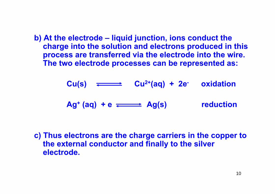
b) At the electrode – liquid junction, ions conduct the charge into the solution and electrons produced in this process are transferred via the electrode into the wire. The two electrode processes can be represented as:
Cu(s) Cu2+(aq) + 2e- oxidation
Ag+ (aq) + e Ag(s) reduction
c) Thus electrons are the charge carriers in the copper to the external conductor and finally to the silver electrode.

11
The net cell reaction occurring in the cell is,
Cu (s) + 2Ag+ Cu2+ + 2 Ag(s)
The voltage of this cell is a measure of the tendency forthis reaction to proceed towards equilibrium. Forexample when copper and silver concentrations are0.200 M, the cell voltage reading of 0.412 V shows thatthe reaction is far from equilibrium.
Now if we connect a resistor, a measurable current flows through the circuit and the cell reaction occurs.As the reaction proceeds, the voltage becomes smaller and smaller until it reaches 0.000 V at which stageequilibrium is reached.

12
Cells which produce electrical energy are called galvanic cells.
Cells which consume electrical energy are calledelectrolytic cells.
A reversible cell can be made galvanic or electrolytic bychanging the polarities. Not all electrical reactions are reversible. Whenever reversibility occurs in the cell, it is termed a chemically reversible cell.
By definition, an electrode where reduction occurs is called cathode and where oxidation occurs the electrode istermed anode.
13
THE ELECTRICAL DOUBLE LAYERThe transfer of an electron from an electrolyte to theelectrode or vice versa can occur only between the electrode surface and a thin layer of the solutionmolecules that are immediately adjacent to it. Thislayer may have a composition very different from thatof the bulk of the solution.
When a positive voltage is applied to silver electrode, immediately a momentary surge of current occurs which rapidly decays to zero if no reactive species is present at the surface of the electrode. This current is a chargingcurrent that creates an excess (or deficiency ) of negativecharge at the surface of the two electrodes.

14
However the layers of solution immediately adjacent to the electrodes acquire a charge of the opposite ion. The charged solution layer now consists of two parts.
(i) A compact inner layer in which the potential decreases linearly with distance from the electrode surface and
(ii) A diffuse layer (d1 to d2) within which the decrease is approximately exponential.
This entire array of charged species and oriented dipoles such as water molecules at the electrode solution interface is known as electrical double layer.

15
ELECTRICAL DOUBLE LAYER

16
Faraday’s law : The amount of chemical reaction occurring at an electrode is proportional to the current.The current is called a faradic current. Under theseconditions an electron transfers easily from theelectrode to the chemical species in the solution.
Under certain conditions even when a voltage is applied to a cell, the electron will not have sufficient energy to either reduce or oxidize at the electrodes. This could happen due to thermodynamic or kinetic requirements for redox reactions are not being met.

17
Therefore applied electrical energy is consumed and converted to heat by friction associated with the motion of the ions. Therefore the ions in the electrical double layer rearrange and adjust to the new potential. Thus each electrode surface behaves as a capacitor. Such a process is called as nonfaradic process and the current is called as nonfaradic current.

18
When faradic current flows in a cell continuous mass transfer of reactive species takes place from the bulk of the solution to the electrode surface through convection, migration and diffusion mechanisms. Convection results from mechanical motion of the solution as a result of stirring or the flow of the solution past the surface of the electrode. Migration occurs due to the movement of the ions due to electrostatic attraction and repulsion of oppositely charged or like charged species. Diffusion occurs due to the motion of the species carried by aconcentration gradient.

19
A major series of analytical methods are based on electrochemical properties of solutions. A solution ofan electrolyte contained in a glass vessel in contact with two electrodes which are connected to an outside source of electrical power can cause a current to flow through a cell.
20
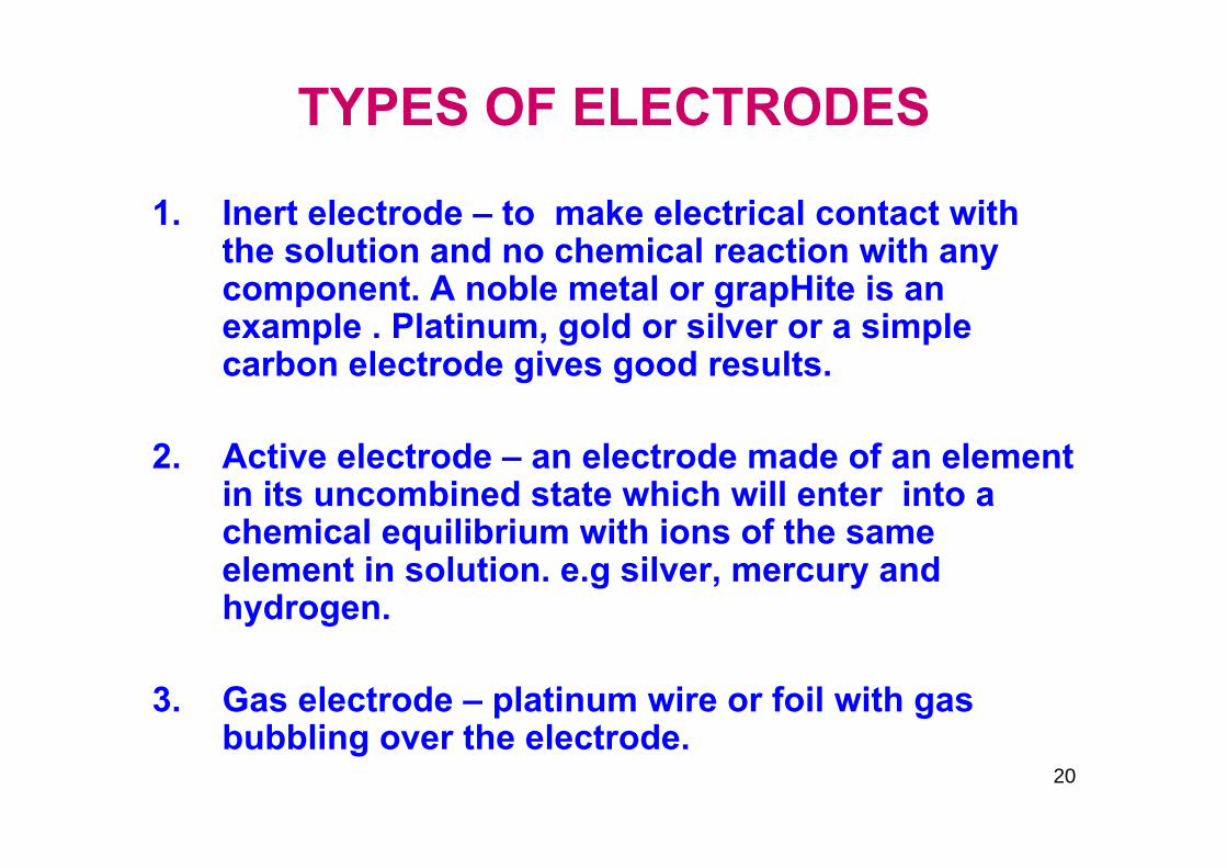
TYPES OF ELECTRODES
1. Inert electrode – to make electrical contact with the solution and no chemical reaction with any component. A noble metal or grapHite is an example . Platinum, gold or silver or a simple carbon electrode gives good results.
2. Active electrode – an electrode made of an element in its uncombined state which will enter into a chemical equilibrium with ions of the same element in solution. e.g silver, mercury and hydrogen.
3. Gas electrode – platinum wire or foil with gas bubbling over the electrode.

21
THE CELL REACTION
Whenever a direct current passes through an electrolytic cell, oxidation and reduction takes place at anode and cathode respectively. At the anode, oxidation takes placewith transfer of electrons from the reduced species to theelectrode.
At the cathode reduction, takes place and electrons are transferred from electrode to the oxidized species. External circuit carries the electrons from anode to cathode. The electrical circuit is completed by ionicconduction through the solution.

22
The generalized redox reaction can be written as
r Ared + s Ba + ……. p Aox + q Bred + …..
Let r = p and s = q then,
(Aox)eq (Bred)eq (Aox)act (Bred)act
(Ared)eq (Box)eq (Ared)act (Box)act
From thermodynamic considerations we get,
ΔG = RT ln Q - RT ln K (R = 8.316 Joules/ mole degree)
and Q =K =

23
From electrochemical reactions we have,
ΔG = - n FEcell
where Ecell – potential in vF – Faraday const 96500 coulombsn – No of electrons transferred per one mol. unit of
reaction.
ΔG - RT RTnF nF nF
ln Q + ln K or Ecell = =

24These are known as “Nernst equations”.
qactox
qactred0
B
pactox
pactred0
AAB
pactox
pactred0
qactox
qactred0
qactRed
qactox
qeqRed
qeqox
Red
pactox
Red
peqox
)(B)(Bln
nFRT - E
and )(A)(Aln
nFRT - E whereE - E
)(A)(Aln
nFRT -
)(B)(Bln
nFRT -
)(B)(B ln
)(B)(B
ln nFRT -
)(A)(Aln
nFRT -
)(A)(A
ln nFRT
B
Acell
AB
pact
peq
cell
E
EE
EE
nFRT
E
=
==
⎥⎦
⎤⎢⎣
⎡−⎥
⎦
⎤⎢⎣
⎡=
⎥⎥⎦
⎤
⎢⎢⎣
⎡−
=

25
rAred pAox + ne- or Aox + ne- Ared
ne- + sBox qBred Box + ne- Bred
For convenience all half reactions are written as reductions.The overall reaction is obtained by subtracting one of these.

The quantities E0 and E0 are called standard potentials for the half reactions and can be evaluated by setting a reaction in which for one half cell the ratios of activitiesare unity and the logarithmic term becomes zero. No valid method has been discovered for setting up only a half cell since a measurement always requires a second electrode. Therefore it is necessary to choosean electrode to arbitrarily assign a zero position on the scale of potentials SHE has been selected for this purpose. This is an electrode in which hydrogen is bubbled at a partial pressure of 1 atom over a platizedplatinum foil in an aqueous solution in which the activity of hydrogen is unity.
26
A B

27
1) A metal in equilibrium with its ions
Zn2+ + 2e Znred E0 = - 0.763 V
Cu2+ + 2e Cured E0 = + 0.337 V
Ag+ + e- Agred E0 = + 0.799 V
E0 values are quoted in V relative to SHE at 250 C.
EA = E0 + RT nf
TYPES OF ELECTRODES
A ln (AOX)
ox
ox
ox

28
2) A metal in equilibrium with a saturated solution of a slightly soluble salt
AgCl + e- Ag + Cl- E0 = + 0.2221 V
Hg2Cl2 + e- 2 Hg + 2 Cl- E0 = + 0.2676 V
Half cells of this type are widely used as reference electrodes which are known as secondary standards.These are easy to fabricate, reproducible and have low temperature coefficient.
(a=1)
(a=1)

Thus we have,
Hg2Cl2 + 2e 2 Hg + 2 Cl- E = 0.246 V SCE(satd kCl)
Hg2Cl2 + 2e 2 Hg + 2 Cl- E = + 0.280 V NCE
AgCl + e- Ag + Cl- E = + 0.237 V (in KCl)
29

30
3) Two soluble species in equilibrium at an inert electrode (say Pt)
Fe3+ + e- Fe2+ + E0 = + 0.771 V
2 Hg2+ + 2e- Hg2 E0 = + 0.920 V
Ce4+ + e Ce3+ E0 = + 1.61 V
The only function of the electrode is to transport electron to or from the ions in the electron.
2+

31
SIGN CONVENTION
Zn2+ + 2e- Zn E0 = - 0.763 V
2H+ + 2e- H2 E0 = 0.0 V
Cu2+ + 2e- Cu E0 = - 0.337 V
E0 values are known as standard electrode potentials. Thus if copper and zinc electrodes are constructed eachin contact with its own ions, copper is found to be positive and zinc is found to be negative as observed in a voltmeter or potentiometer.

32
A half cell is said to be reversible if a change in the direction of current flow reverses the half reaction. Most of the half cells act reversibly in normal circumstances.Consider Zn/AgCl system:
Zn Zn2+ + 2e-
2e- + 2 AgCl 2 Ag+ + Zn2+ + 2 Cl-
However if this cell is connected to a source of electricity at high voltage to force current in the reverse direction, the reactions will be:
REVERSIBILITY

33
2H+ + 2e- H2
2Ag + 2Cl- 2AgCl + 2e-
and the overall reaction will be
2Ag+ + 2H+ + 2Cl- 2AgCl + H2
Thus it seen that Ag/AgCl electrode is reversible but Zn/HCl half cell is not.

34
POLARIZATION
An electrode is said to be polarized if its potential is at variance with the Nernst equation. This may be due to changes in the actual concentration of ions at theelectrode surface known as concentration polarization.

35
OVERVOLTAGE
According to thermodynamic definitions any half cell isoperating irreversibly if apprecial current is flowing.It is always greater than the corresponding reversiblepotential as calculated from the Nernst equation. Thedifference between the equilibrium potential and actualpotential is known as overvoltage. It is essentially theextra driving force necessary to cause a reaction totake place at an appreciable rate. Of special importanceis the overvoltage due to hydrogen ions conversion to H2 gas which would take place at 0 volts if no overvoltage is applied.

36
Fe3+ and Zn2+ can be reduced to free metals at a mercury cathode even though their standard potentials (E0) are more negative than SHE because the high overvoltage of H2 ion on mercury pressure liberalization. At a platinum cathode these ions cannot be reduced from an aqueous solution as the potential cannot exceed that required for H2 liberation.
37
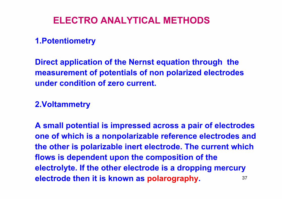
1.Potentiometry
Direct application of the Nernst equation through the measurement of potentials of non polarized electrodes under condition of zero current.
2.Voltammetry
A small potential is impressed across a pair of electrodes one of which is a nonpolarizable reference electrodes and the other is polarizable inert electrode. The current which flows is dependent upon the composition of the electrolyte. If the other electrode is a dropping mercury electrode then it is known as polarography.
ELECTRO ANALYTICAL METHODS

38
Amperometry is similar to polarograpHy but both electrodes
are polarizable. Usually current – voltage curves are recorded in these studies.
3. Conductivity
Two identical electrodes are employed and the conductanceof the solution between then is measured .
4. Oscillometry
Changes in conductance and other properties (dielectric constant) by using high frequency AC.

39
5. Coulometry
Faraday’s laws of electrolysis is used to define the quantity of chemical change
6. Chronopotentiometry
Recording of transient currents flowing immediately after closing a AC circuit and before attainment of equilibrium.

40
POTENTIOMETRY
According to the Nernst equation, potential of a reversible electrode permits calculation of the activity or concentration of the component of a solution.
EAg = E0 + RT ln [Ag+]nF [Ag ]
ESCE = + 0.246 V
Ag

41
Ecell = EAg - ESCE
= E0 - ESCE + RT ln (Ag+)nF
log (Ag+) = Ecell - E0Ag + ESCE
2.303 (RT/nF)
= + 0.400 – 0.799 + 0.2460.0591
= 2.59 or [Ag+] = 2.57x10⁻³ M
Ag

42
Note :
(1) We always subtract the more negative from the more positive.
(2) 2.303 RT/nF = 0.0591 at 250 C.
(3) pAg = - log [Ag+]

As another example consider a cell of platinum electrode dipping in 0.1N FeSO4 with SCE as a counter electrode. A potential differences is 0.395 volt is obtained. It is desired to obtain the percentage of Fe(II) which has been converted to Fe(III) by oxidation.
43

44
We write, E = E0 + RT ln (Fe3+)nF (Fe2+)
Ecell = E + RT ln (Fe3+)nF (Fe2+)
log (Fe3+) = Ecell – E0 + ESCE
(Fe2+) 0.0591= - 2.20 V
Fe3+/Fe2+ = 6.3 x 10⁻³ or 0.63 percent.
Fe3+/ Fe2+ Fe3+/ Fe2+
Fe3+/ Fe2+
Fe3+/ Fe2+

45
THE CONCENTRATION CELL
If two identical electrodes are placed in solutions differing only in concentrations but connected by a salt bridge the potential between the two electrodes is related to the ratio of the two concentrations.
Ag / AgCl / Cl (x) // Cl (s) / AgCl / Ag
Two cases arise :
- -

46
Case 1
Suppose the standard is 0.1000 M. Its single electrode potential is given by,
Es = + 0.222 - 0.0591 log 0.1000 = + 0.281 V.
If the unknown is more concentrated say 0.1500 M then
Ex = + 0.222 - 0.0591 log 0.1500 = + 0.271 V.
Thus Ecell = Es – Ex = + 0.010 volt.

47
Case 2
Suppose the unknown is 0.680 M then
Ex = 0.222 – 0.0591 log (0.0680) = 0.291 volt and
Ecell = Ex - Es = + 0.010 V
Thus any measured potential is open to ambiguous interpretations which may be avoided by noting that the interpretation corresponds to more positive of the two.
The concentration cell provides a convenient tool foranalysis of pH.

48
The pH is defined as the negative logarithm of the activity of hydrogen ion expressed in molarity.
pH = - log [aH+] = - log10 [H+]
For a solution of 2.0 x 10⁻⁴ M HCl,
pH = - log (2 x 10⁻⁴) = 4 – log 2 = 3.699 ~ 3.70

49
The measurement of pH is accomplished with hydrogen electrode in a concentration cell. The potential is given by:
Ecell = 0.0591 log [H+]std
[H+]unknown
For a SHE electrode, Ecell = - 0.0591 log [H+] = 0.0591 pH
or pH = Ecell
0.0591
For a calomel electrode, pH = Ecell - 0.2460.0591

50
Thin membranes of certain varieties of glass are permeableto hydrogen ions and a glass electrode is reversible. Itcontains a solution of known and unchanging pH (a chloridecontaining buffer) and a reference electrode such ascalomel or Ag/AgCl electrode. The tube is permanentlysealed at the top. When this is dipped into an unknown aconcentration cell results as shown below:
Inner pH 7 Glass membrane test solution ExternalSCE buffer SCE
THE GLASS ELECTRODE
51
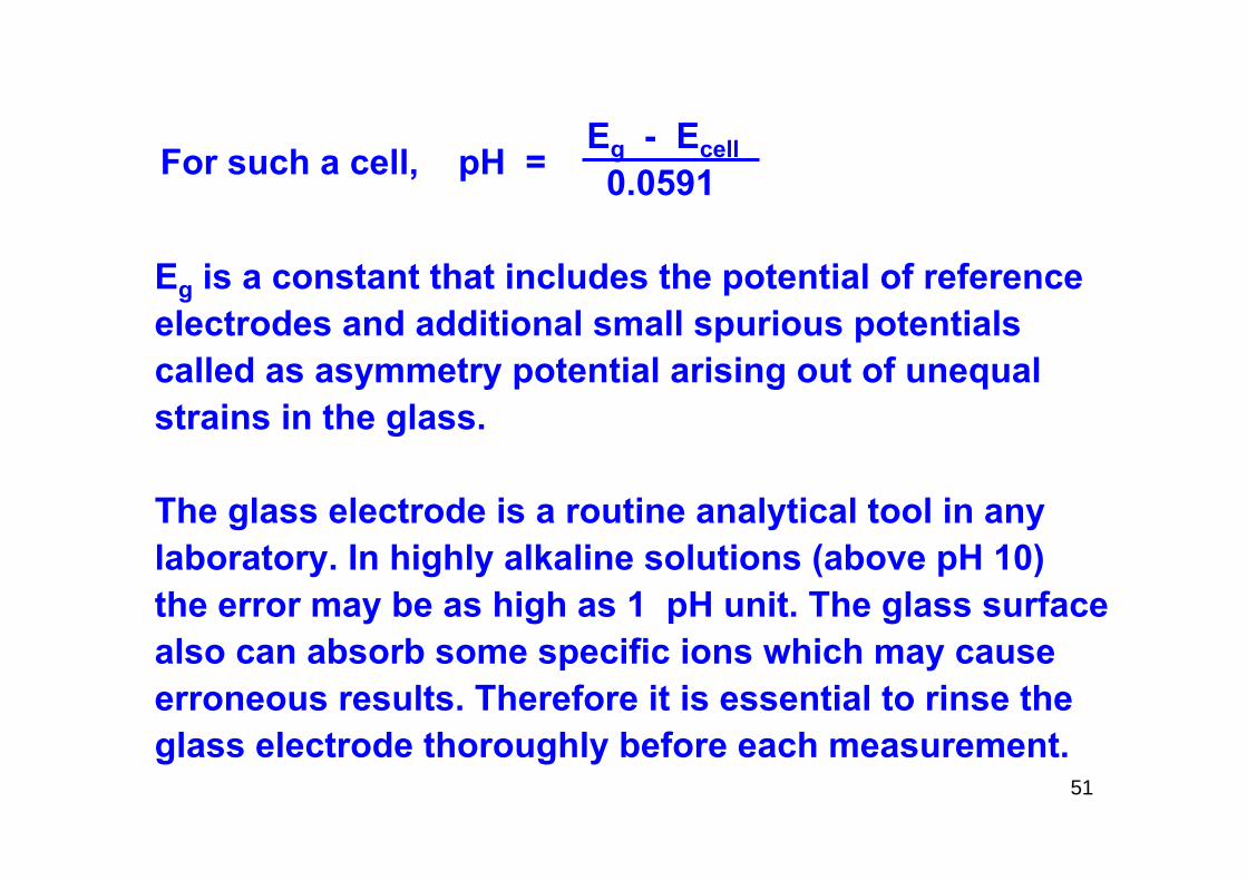
Eg - Ecell0.0591
Eg is a constant that includes the potential of reference electrodes and additional small spurious potentials called as asymmetry potential arising out of unequal strains in the glass.
The glass electrode is a routine analytical tool in any laboratory. In highly alkaline solutions (above pH 10) the error may be as high as 1 pH unit. The glass surfacealso can absorb some specific ions which may cause erroneous results. Therefore it is essential to rinse the glass electrode thoroughly before each measurement.
For such a cell, pH =

52
QUINHYDRONE ELECTRODE
A platinum electrode in equilibrium with an equimolarmixture of quinine and hydroquinone.
E = E0 + 0.0591 log [H+] = (0.699 – Ecell )2
(0.0591)
Not useful for solutions above pH 9 and in presence of strong oxidizing and reducing agents.
O
O
OH
OH
+ 2H+ + 2e-

53
ANTIMONY ELECTRODE
Antimony wire coated with its oxide can also be usedas a reference electrode.
2Sb + 3 H2O Sb2O3 + 6H+ + 6E-
This electrode is not as fragile as the glass electrode and is useful in some industrial applications. But the potential of this electrode depends on the method of preparation and on the nature of solution.

54
POTENTIOMETRY

55
A great many reactions may be followed by potentiometrictitrations provided there is addition or removal of some ionfor which an electrode is available. Thus acid – base titrations can be followed by a pH electrode and calomel reference electrode by adding the titrant and measuring the potential or pH which can be plotted vs the titrand.

The pH is given by,
Ecell – 0.2460.0591
If the curve is essentially vertical in its steepest portion, equivalence point is easily reached. Otherwise derivative plotting (ΔE/ΔV) is more useful. Let us consider the titration of 100 ml of 0.01 N HCl with 1.00 N NaOH. Calculated values of the potential and pH are shown in the next slide.
56
pH =

57
Volume added (ml)
[H+] pH E (VSSCE) V
0.000.500.900.990.9991.0001.00011.0011.101.502.00
10-2
5 x 10⁻³
10-3
10-4
10-5
10-7
10-8
10-9
10-11
2 x 10-12
10-12
22.33.04.05.07.08.09.0
11.011.712.0
0.3640.3720.4230.4720.5410.6590.7180.7770.8950.9360.954
Titration of 100 ml of 0.01 N HCl by 1.00 N NaOH

58
Titrations involving precipitations are not easily performed as it is difficult to see the end point. But such titrations can be easily performed with potentiometric titrations e.g. precipitation of silver ion with chloride 0.01N AgNO3 titrated by 1.00 N NaCl.
The potentials can be calculated by the Nernst equation
Ecell = 0.553 – 0.059 pAg
At the equivalence point, KSP = [Ag+][Cl-] = 1x10⁻¹⁰
or [Ag+] = √KSP = 10-5 M

59
Volume [Ag+] pAg E0.000.500.900.990.9991.0001.0011.011.11.502.00
10-2
5 x 10⁻³
10-3
10-4
1.6 x 10⁻⁵
10-5
6.4 x 10-6
x 10-6
x 10-7
2 x 10⁻⁸
10-8
2.02.33.04.04.85.05.26.07.07.78.0
0.4350.4170.3760.3170.2700.2580.2460.1990.1400.0980.081
Titration of 0.01 N AgNO3 with 0.1 N NACl
60
The curve will be similar to acid base titrations.
The precision obtainable depends upon the degree of insolubility of the precipitate. If the product issomewhat soluble the slope of the curve at theequivalence point will be less steep and more differentto assess.
Reactions involving complexation exhibit more complicated titration curves. In the titration of silver against cyanide we have,

61
Ag AgCN Ag(CN)
Near the start of this titration Ag(CN) ions are formed. At the completion of this reaction, the potential of Ag electrode shows a sudden decrease after which the insoluble AgCN will start precipitating. When all the CN- is used up another jump in the potential occurs.
Other example include titration of cyanide, iodide, bromide, chloride, SCN with silver .
First equivalent point corresponds to AgCN, second one to iodide and third to bromide etc.
-
2
-
2

62
OXIDATION – REDUCTION TITRATIONS
These are followed by a simple platinum indicator electrode and SCE. Consider the reaction of stannous chloride with ceric sulphate. The reaction is represented by
Sn2+ + Ce4+ Sn4+ + 2Ce3+
and the euilibrium constant is given by
(Sn4+)(Ce3+)2
(Sn2+)(Ce4+)2
At the start, the ratio of Sn4+/Sn2+ is nearly zero and log [Sn4+]/[Sn2+] has a large negative potential value.
K =

63
After the first addition of the oxidant of some Sn2+ is converted to Sn4+ and the potential is given by,
E = E0Sn / Sn + 0.0591 log [Sn4+]
2 [Sn2+]
Also some cerium is present and hence,
E = E0Ce / Ce + 0.0591 log [Ce4+]
[Ce3+]
4+ 2+
4+ 3+

64
Now as the platinum electrode can not have two potentials The E values have to be identical. Hence ,
E0Ce / Ce + E0
Sn / Sn = 0.0591 [Sn4+] [Ce4+]2 [Sn2+] [Ce3+]
0.0591 (Sn4+ )(Ce3+)2
2 (Sn2+)(Ce4+)
0.05912
4+ 3+ 4+ 2+
log - 2 log
= log
= log k

65
Substituting the known values of E0s we get
(1.61 – 0.15)0.0591
At the equivalence point it can be easily seen that
(Ce3+) = 2 (Sn4+) and (Ce4+) = 2 (Sn2+) and
(Sn4+) (Ce3+)(Sn2+) (Ce4+)
3
= log k or k = 2.5 x 1049
= = √k = 2.92 x 10¹⁶

66
We can now substitute this value of ionic ratios andcalculate
E = 0.15 + 0.0591 log (2.92 x 10⁶) = 0.64 volt
E = 1.61 – 0.0591 log (2.92 x 10⁶) = 0.64 volt
Note that the same value is obtained both ways which is expected.
Many redox reactions especially those with permanganate, dichromate, nitrate and similar oxidants have a strong dependence on pH and the potential calculations become complicated.

67
For example, in the permanganate titration of iron theequilibrium constant is given by,
(Fe3+)5 (Mn2+)(Fe2+)5(MnO4) (H+)8
and at the equivalence point,
(Fe3+) (Mn++) (Fe2+) (MnO4) -
-K =
K = = = K1/6 (H+)8/5

68
The reaction is as follows:
MnO4 + 8H+ + 5e Mn2+ + 4H2O
5Fe2+ 5Fe3+ + 5e
E = E0 + 0.059 log [MnO4][H+]8
5 [Mn2+]
= 1.52 + 0.059 log [MnO4][H+]8
5 [Mn2+]
-
-
-

69
Also we have
E = E0 + 0.059 log [Fe3+]5
5 [Fe2+]5
= 0.77 + 0.059 log [Fe3+]5 [Fe2+]5
5
At equilibrium,
1.52 + 0.059 log [MnO4][H+] = 0.77 + 0.059 log [Fe3+]5 [Fe2+]5
5 [Mn2+] 5
-

70
or log [Mn2+][Fe3+]5 = 5 (1.52-0.77) = 63.5 or [MnO4][Fe2+]5[H+]8 0.059
K = [Mn2+][Fe3+]5 = 3 x 1063
[MnO4][Fe2+]5[H+]8
The large value of K shows that the reaction is virtually complete. Suppose we titrate 10 ml of 0.1 KMnO4 with0.1 N FeSO4 then [Fe+++] = 0.01 N at equivalence point, [solution at eq pt is 100 ml].
[Mn2+] = 1/5 [Fe3+] = 0.002 N and [Fe2+] = x.
-
-

71
Let excess of permanganate solution at the equivalence point be 1 drop or 0.05 ml which corresponds to:
0.05 x 0.1 = 5 x 10⁻⁵ N = [MnO4]100
Substituting these values in the equilibrium equation,
K = (2 x 10⁻³)(1 x 10⁻²)5 = 3 x 1063
(5 x 10⁻⁵)(x5) x 18
or x = 5 x 10-15 N
-

72
Consider a redox reaction titration of 100 ml of 0.1 N ferrous ion with 0.1 N ceric ion in pressure of sulphuric acid using ferric/ferrous electrode and ceric/cerous electrode.
Ce4+ + Fe2+ Ce3+ + Fe3+
Thus we have,
E1 = E1 + 0.0591 log [Fe3+] 1 [Fe2+]
= + 0.75 + 0.0591 log [Fe3+] [Fe2+]
0

73
E2 = E2 + 0.0591 log [Ce4+] 1 [Ce3+]
= +1.45 + 0.0591 log Ce4+ Ce3+
At equilibrium, the rate constant is given by,
log K = log [Ce3+] [Fe3+] = 1.45 – 0.75 = 11.84 or K = 7x10¹¹
[Ce4+] [Fe2+] 0.0591
Therefore the reaction is virtually complete.
0

74
Upto the equivalence point all the ceric ions will be utilized to oxidise ferrous to ferric (Fe2+ Fe3+ ).
When
10 ml Ce(SO4)2 is added, E1 = 0.75 + 0.0591 log 10/90 = 0.69 V50 ml Ce(SO4)2 is added, E1 = 0.75 + 0.0591 log 50/50 = 0.75 V90 ml Ce(SO4)2 is added, E1 = 0.75 + 0.0591 log 90/10 = 0.81 V99 ml Ce(SO4)2 is added, E1 = 0.75 + 0.0591 log 99/1 = 0.87 V99.9 ml Ce(SO4)2 is added, E1 = 0.75 + 0.0591 log 99.9/0.01 = 0.69 V

75
At 100 ml, E = E1 + E2 = 0.75 + 0.145 = 110 V2 2
100.1 ml Ce(SO4)2 is added, E1 = 1.45+0.0591 log 0.1/100 = 1.27 V101 ml Ce(SO4)2 is added, E1 = 1.45+0.0591 log 1/100 = 1.33 V110 ml Ce(SO4)2 is added, E1 = 1.45+0.0591 log 10/100 = 1.39 V190 ml Ce(SO4)2 is added, E1 = 1.45+ log 90/100 0.0591 = 1.45 V

76
At 99.9 ml, Fe2+ = 0.1 x 0.1/199.9 = 5 x 10⁵ or pFe = 4.3
At 100 ml, [Fe2+] = 0.05 N, [Fe2+] = 5 x 10⁻²/ 8.5 x 105
= 6 x 10⁻⁸ N or pFe = 7.2
At 100.1 ml [Fe3+] is practically unchanged at 5 x 10⁻² N and
E = E1 + 0.0591 log [Fe3+] = 0.75 + 0.0591 log 5 x 10⁻²
1 [Fe2+] [Fe2+]
or [Fe2+] = 1 x 10⁻¹⁰ or pFe = 10
Thus pFe changes from 4.3 7.2 10 within a volume change of 99.9 100 100.1. These values are important for the choice of indicators for the titration.

77
POLAROGRAPHY
78
If a steadily increasing voltage is applied to a cellincorporating a large quiescent mercury anode and aminute mercury cathode (composed of a successionof minute mercury drops falling from a capillary tube)it is possible to construct a reproducible current –voltage curve. The electrolyte is a dilute solution of thematerial under investigation (which must be electroactive) in a suitable medium containing an excess of anindifferent electrolyte (supporting electrolyte) to carry bulkof the current and raise the conductivity of the solutionthus ensuring that the material to be determined if charged,does not migrate to the dropping mercury cathode.

79
From an examination of the current – voltage curve,nature and concentration of the analyte may beobtained. Heyrovsky and Shibata developed anapparatus which increased the applied voltage at asteadily increasing rate and simultaneously recordedthe C-V curve. Since these curves are a graphicalrepresentation of the polarization of the droppingmercury electrode, the apparatus was called a polargraph and the curves are called polarograms.

80
The basic apparatus consists of a dropping mercuryelectrode which is referred to as microelectrode orindicator electrode. The anode is a pool of mercury and itsarea is correspondingly large, so that it may be regardedas incapable of being polarized i.e its potential remainsconstant in a medium containing anions (Cl- ,SO4 etc) forming insoluble salts with mercury. This acts as the reference electrode (whose exact potential is not knownbut depends upon the supporting electrolyte concentration.The polarization of the cell is thus governed by the reactions occurring at the DME.
2-
81
Inlet and outlet tubes are provided for purging thedissolved oxygen by hydrogen (or nitrogen ) before theexperiment (otherwise the C-V curve for oxygen is alsoobtained). P is a potentiometer by which up to 3 V isgradually applied to the cell. S is a shunt for adjustingthe sensitivity of the galvanometer G. The currentcathode curve is recorded with reference to the anode(mercury pool) or SCE.
The initial potential of the DME is indeterminate and assumes any potential applied. When it assumes a potential different from that which it had in the absence of electrical connections it is said to be polarized.
82
Consider a cadmium solution along with NaCl in anoxygen free medium. When an external emf is appliedtwo phenomena occur,
1. All the positively charged ions will be attracted to the negative electrode by a force proportional to the attraction of the oppositely charged bodies to each other.
2. By a diffusing force arising out of concentration gradient produced at the electrode.

83
The total current passing through the cell can be regarded as the sum of these factors. A typical current voltage curve is shown here.
The indicator electrode being perfectly polarizable, assumes the correspondingly increasing negative potential applied to it. But from A to B practically no current will pass through the cell.
At B where the potential is equal to the deposition potential of the cadmium ions, the current suddenly starts to increase and the indicator electrode becomes depolarized by the cadmium ions which are then discharged upon the electrode surface to form metallic cadmium. Consequently a rapid increase in the current flowing through the cell will be observed.

84
At the point C the rate of supply of cadmium ions from the bulk of the solution to the indicator electrode surface becomes equal to the rate of their deposition.Hence at potentials greater than C, the concentration ofundischarged cadmium ions at the micro electrode surface is negligibly small compared to the cell ions in solution. No further increase in current can be expected after C but a small steady increased current will result between C and D since the limiting current is now fixed by the rate at which cadmium ions reach thesurface.

85
A rotating pt wire (0.5mm diameter) can also be used
as a polarizable micro electrode for obtaining current –
voltage curve, but the most satisfactory one is dropping
mercury electrode from a head of 40-50 cm of mercury from
a capillary (0.05-0.05mm diameter and 5-9 cm long ) in
small uniform drops.

86
The DME has several advantages:
Its surface is renewable, reproducible and smooth which eliminates passivity or poisoning effects.
Mercury forms amalgams with many metals (solid solutions)
The diffusion current assumes a steady value immediately after changing the potential and is reproducible.
The large hydrogen over voltage on mercury renders the deposition of metals such as alkali metals, aluminum ions, manganous ions etc which are not easily amenable to platinum microelectrode.
The surface area can be calculated easily.

87
The DME can be worked from +0.4 to -2.0 V w.r.t SCE. Above 0.4 V, the mercury dissolves and gives an anodic wave (Hg+).
At potentials more negative than - 1.8 V, visible H2evolution occurs and supporting electrolytes commenceto discharge. By using tetra alkyl ammonium hydroxideor their salts, the range may be extended to -2.6 V.
For convenience and measurement of half wave potentials the anode potential may be measured with a saturated calomel electrode using a salt bridge.

88
THEORETICAL PRINCIPLES
Residual current
Mercury is unique in remaining electrically uncharged when it is dropping freely into a solution containing an indifferent electrolyte such as KCl or KNO3. But even in such cases a small current will flow before the decomposition of the analyte. This current increases linearly with increased voltage, but it is observed even when extremely pure solutions are used. Therefore it cannot be due to any impurities but it is residual non faradic current or condenser current. This is due to the electrical double layer of positively and negatively charged ions. The capacity of double layer varies depending upon the (metal e.g. mercury) and the potential applied.

89
In practice traces of impurities present in the indifferent electrolyte do cause small and imperceptible currents superimposed upon the condenser current. All these are called ‘residual current’ and in practical work, this current is automatically subtracted from the total observed current by proper extrapolation.
90
Migration current
Electro active material reaches the surface of the electrode largely by two processes:
(i) Migration of charged particles in the electric field caused by the potential difference existing between the electrode and the solution and by diffusion of ions. Migration current can be made negligible by the addition of large quantity of indifferent electrolyte ( > 100 times of the analyte).
Under such conditions practically all the current will be transported by the K+ and Cl- ions and the analyte can reach the electrode only by diffusion. But they will not reach at the electrode.

91
Diffusion current
Under these conditions the potential gradient is compressed very close to the electrode surface but itcannot permit the transport of cadmium ions. Thereforethe limiting current is solely due to diffusion current.

92
D.Ilkovich (1934) examined the various factors governing the diffusion current and deduced the equation,
id = 607 n C D1/2 m2/3 t1/6
where id = diffusion current, μAn = number of electrons involved in the reductionC = concentration of reducible substance, mM/litD = diffusion coefficient of the reducible substance
cm2/sec m = mass of the mercury flowing through the
capillary, mg/st = drop time in seconds

93
The constant, 607, is a combination of several natural constants including the Faraday. The id and 607 are temperature dependent and hence id is quoted always at specified temperature. Apart from temperature viscosity, molecular or ionic state of the electroactivespecies, dimension of the capillary and the pressure on dropping mercury. Precise measurement of id requires temperature control of ± 0.2 0C.
The product m2/3t is important because it permits the comparison of difference capillaries. Stirring of the solution is not permissible because the drops have to fall under their own weight.

94
Polarographic maximaSome times C-V curves of DME exhibit pronounced maxima which are reproducible. These maxima vary in shape from sharp peaks to rounded humps which gradually decrease to normal id curve as the potential is increased.
For measuring the true id, the maxima must be eliminated or suppressed. Fortunately this can be done with the addition of a dye stuff (methyl red, gelatin, fuchsine etc). It forms an adsorbed layer on the aqueous side of the mercury solution interface which resists compression. This prevents streaming movement of the diffusion layer at the interface thus reducing maxima. Higher concentration of the suppressors usually suppresses id itself. Triton-x100 (0.002-0.004%), methyl cellulose (0.005%) are also used.

95
HALF WAVE POTENTIALS
Since solutions studied polarographically are very dilute, we can assume that the activity of the cationdoes not differ from its concentration in the bulk as well as in the amalgam. Polarography is concerned with electrode reaction at the indicator electrode involving electron transfer between the electrode and analyst. During the reduction of an oxide electrons leave the cathode, react in solution with the formation of the equivalent amount of the reductant.
Similarly during the oxidation of a reductant at the anode electrons pass from the solution to the electrode and form equivalent of the oxidant.

96
Thus ,
Mn+ + ne- M(Hg)
EDME = E0 – RT ln [M][Hg]nF [Mn+]aq
Since the current I is limited by diffusion,
i = k [Mn+]aq - [Mn+]aq )
where [Mn+]aq represents the point of contact with mercury surface.
. . . . . . . . (1)
0
0

97
For the limiting current id, [Mn]aq becomes very small.
id = k[Mn+]aq
From the Ilkovich equation,
k = 607 n C D1/2 m2/3 t1/6
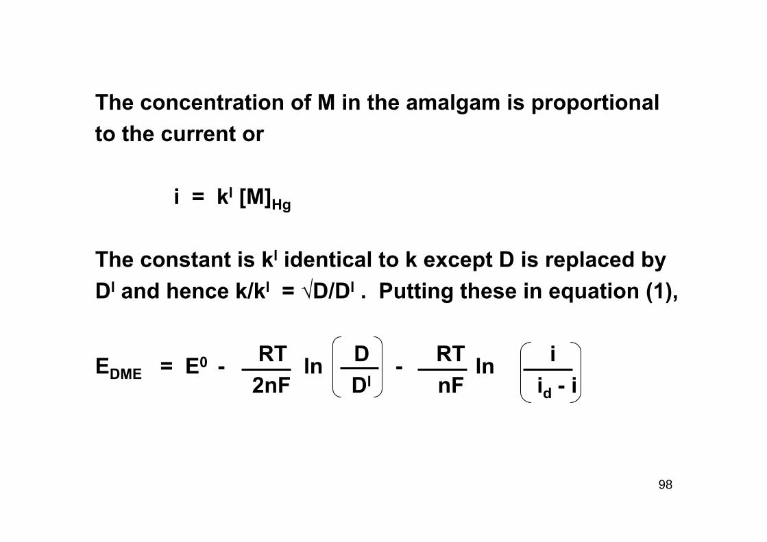
The concentration of M in the amalgam is proportional to the current or i = k [M]Hg
0
l
98
The concentration of M in the amalgam is proportional to the current or
i = kl [M]Hg
The constant is kl identical to k except D is replaced by Dl and hence k/kl = √D/Dl . Putting these in equation (1),
RT D RT i2nF Dl nF id - i
EDME = E0 - ln - ln

99
At the point where i = 1/2 id,
RT D2nF Dl
Hence,
RT inF id - i
lE1/2 = E0 - ln = E0
EDME = E1/2 - ln

100
The potential at E1/2 is termed the half wave potentialand E1/2 is the characteristic constant of any red–ox system and its value is independent of the concentration of the oxidant [OX], in the bulk of the solution.
The theoretical treatment of anodic waves is similar to that of the cathodic wave outlined above.

101
The same result can be obtained as follows:
Ox + ne Red
E = E0 + RT ln aox or (1)nF ared
E = E0 + RT ln [ox]0 (2)nF [Red]0
where 0 refers to the concentration at the electrode surface and E refers to the value during the life of a mercury drop.

102
The current i at any point on the wave is determined bythe rate of diffusion of the oxidant from the bulk of thesolution to the electrode surface under a concentrationgradient [Ox] to [Ox]0 .
i = K[ox] - [ox]0 (3)
= K[ox] = id
when [ox]0 = zero , id = diffusion current , K = Ilkovichcurrent.
Putting the value of [ox]0 in equation 3, we get
[ox]0 = (id - i ) / K

103
The concentration of the reductant [Red]0, on the surface at any value of i will be proportional to the rateof the diffusion of the reductant from the surface of theelectrode into the mercury drop. Hence,
i = k [Red]0 substituting this in equation (3)
E = E0 + RT ln K + RT ln id - inF k nF i
= E0 + RT ln id – inF i
l

104
where E0 = E0 - k and k = RT ln KnF k
when i = id / 2 ,
E = E1/2 = E0 + RT ln id/2 = E0 and at 250 CnF id/2
E = E1/2 + 0.0591 log id – in i
Curve log id - i Vs E gives a straight line with slope 0.0591/nand intercept E0l = have wave potential. This equation is termed as the equation of the polargraphic wave.
l l
l l
l 0
l

105
It follows that if log [(id - i) / i ] is plotted against the potential of the microelectrode a straight line with a slope of 0.0591/n is obtained. The intercept of the graph upon the vertical axis gives the half wave potential of the system. Hence n may be determined. E1/2 is also known as the decomposition potential. Thewave should be steeper for aluminum and lanthanum than lead or cadmium than alkali metals or thallous ion.

106
If the reaction at the indicator electrode involvescomplexation, satisfactory polarographs can be obtained only if the dissociation of the complex ion is very rapid as compared with the diffusion rate so that the concentration of the sample ion is maintained constant at the electrode interface.

107
Let us consider reduction of a complex ion :
MXp Mn+ + pXb-
Kinstab = [Mn+][Xb-]P
[MXp ]
then we can write
MXp + ne + Hg M(Hg) + pXb- and hence
E1/2 = E0 + 0.0591 log kinstab - 0.0591 log [Xb-]p
n n
(n - pb)+
(n - pb)+
(n - pb)+
108
Here p is the coordination number of the complex ion formed and X is the complexing agent. The more stable the complex ion, more negative will be the half wave potential. Thus there will be a shift of the E1/2 values by complexations. Copper in nickel, lead etc., can be complexed with CN- ions and hence nickel and lead can be determined.

109
Polarographic analysis can be carried out if the concentrationof the analyte is 10-4 -10-3 molar and the volume of the solution is between 2 and 25 ml. However it is not uncommon to come across 10-2 M and as low as 10-8 M concentrations using volumes less than 1ml. The reproducibility of duplicate analysis may be ± 2 %.
Saturated solutions of oxygen at ambient temperature (2 .5 x 10- M ) give two waves according to the reactions,
O2 + 2H20 + 2e H2O2 + 2OH- (alkaline solution)
O2 + 2H+ + 2e H2O2 (acid solution)

110
The second wave is
H2O2 + 2e 2OH- (alkaline solution)
H2O2 + 2H+ + 2e 2H2O
Therefore oxygen needs to be removed by passing nitrogen through the analyte. Further a 0.005% gelatin should be added to remove the appearance of maxima.

111
If the E1/2 differ by at least 0.4 volts (for univalent ions) and by 0.2 V for divalent ions, they can be easily determined. For E1/2 which overlap each other, complexation can be employed to displace them to more negative potentials. Precipitation, electrolytic deposition etc., can be employed to advantage if complex analysis has to be carried out.
Nickel, zinc in pure copper salt can be dissolved in ammoniacal solutions(NH4Cl) and electrolysed at about- 0.7 volt vs SCE. Then determine zinc and nickel. As less as 0.00001 % nickel can be determined in this way.

112
QUANTITATIVE METHODS
1) Wave height – concentration plots
Prepare several different standards and determine the polarograms using maximum supporting electrolyte and maxima suppressor. Plot wave height vsconcentration and determine the unknown. Read concentration of the unknown prepared in the same way by referring to the calibration curve. Bracketing technique is useful for accurate analysis.

113
2) Pilot ion method
The relative diffusion currents of ions in the same supporting electrolyte are independent of the characteristicsof the capillary electrode and temperature. Determine the relative wave height of the unknown and with some standard or pilot ion added in known amounts and compare these with the ratio for known amounts of same two ions. This procedure is limited to applications withminimum 0.2 V difference for the ions under investigation.

114
3) Method of standard addition
Determine the polarogram of the unknown solution. Add a known amount of the same ion to the same cell and record a second polarogram.
If i1 is the diffusion current of the unknown in vol V of concentration Cu and
i2 is the diffusion current after v ml of standard solution of concentration Cs is added, then we have
i1 = k Cu and i2 = k(VCu + v Cs) / (V + v)

115
Thus k = i2 (V + v) / (VCu + v Cs) and
Cu = i1 v Cs(i2 – i1) (V + v) + i1v
The accuracy of the method depends upon the precision with which the two volumes of the solution and corresponding id s are measured. Here the assumption is made that the wave height is a linear function of the concentration in the range of concentration employed. Best results are obtained when wave height is approximately doubled by the standard addition.

116
MEASUREMENT OF WAVE HEIGHTS
• Fig to be inserted

117
KARL FISCHER TITRATION
For the determination of small amounts of water Karl-Fischer proposed a reagent prepared by the actionof sulphur dioxide upon iodine dissolved in pyridine and methyl alcohol.
118
In the first step sulphur dioxide(SO2) is oxidized by iodine and an intermediate compound pyridine sulphur trioxideis formed. This is the inner salt of pyridine N-sulphonicacid.
The second step is the formation of pyridinium methyl sulphate which prevents the pyridine complex from reacting with another molecule of water or other hydrogen active compound. Hence one molecule of I2 is equivalent to one molecule of water.

119
The original KF reagent is prepared with excess of methanol which serves as a reactant as well as a diluent. This reagent is somewhat unstable and needs frequent standardization. A more stable reagent may be prepared from ethylene glycol monomethyl ether (methyl cellosolve).
Freshly prepared reagent has a deep reddish brown colourand the spent reagent is pale yellow straw colour. So that it can be used as a direct titrant also. But the decomposed reagent also has a brownish colour and the end point detection is difficult. It is therefore preferable to add a slight excess of the reagent and titrate the excess with a standard solution of water in methanol. The end point is determined electrometrically.

120
If a small e.m.f is applied across two platinum electrodesimmersed in the reaction mixture, a current will flow as flow as long as free iodine is there to remove hydrogenand depolarize the electrode. When the last trace of iodine is removed the current will decrease to zero or very close to zero.
Conversely the technique may be combined with a direct titration of the sample with the KF reagent. In this case any excess of iodine causes the current to rise sharply. This is a more elegant method.

121
The apparatus is very simple. The source is a 3 V battery (torch) , M is a microammeter, R is a 500 ohm resistor, 0.5 watt radio potentiometer. The potentiometer is set so that there is a potential drop of about 80 mV across the electrodes and does not require adjustment until the battery is exhausted.
KF reagent may be standardized with 5-6 mg water in methane or with pure disodium tartrate dihydrate. This contains 15.66% of water.

122
The reagent may be applied to samples with the following requirements.
They should not react with the reagents or hydrogen iodide to yield water.
They are miscible with the reagent and preferably do not cause precipitation of the pyridine complexes formed during the titration.
They will conduct electric current.

123
The reagent my be used for determining water present in the hydrated salts or which is absorbed on the surface of the solids. It is a very rapid and direct method compared to drying processes. A sample of the powder containing 90 – 100 mg of water is dissolved or suspended in 25 ml methanol. The mixture is titrated with KF reagent to the usual electrometric end point. An end point stable for about 15 seconds indicates the complete reaction.

124
The KF titration has been successfully applied to barium, cadmium, cobalt, lead, magnesium, nickel, sodium, zinc, uranyl acetate, calcium lactate, malonate, propionates, sodium citrate, napthionates, succinates, formaldehyde and ammonium oxalate, phosphates, potassium and Cr, Sr, Cd, Sn chlorides, Cr, Co, Hg nitrates, Al, Co, Fe, Mg, Mn, Ni, Zn sulphates etc.
Activated alumina (7.02), silica gel (5.48), CaCl2(11.28), calcium sulphate (5.31) are used as standards.

125
INTERFERENCES
(i) Oxidising agents such as chromates, dichromates, cupric, ferric salts, peroxides etc., interfere.
MnO2 + 4 C5H5NH+ + 2I- Mn2+ + 4C5H5N + I2 + 2H2O
(ii) Reducing agents such as thiosulphates, Sn2+ , sulphides
(iii) Basic oxides ZnO + 2C5H5NH Zn2+ + 4C5H5N + H2O
Weak oxy acids NaHCO3 + C5H5NH+ Na+ + H2O + CO2+ C5H5N
Borates H2BO3 + 3CH3OH B(OCH3)3 + 3H2O

126
TYPICAL RESULTS
(i) 1 ml of RF reagent = 6.66 mg water
Vol of KF reagent added = 2.0 ml
Excess of KF reagent = 1.18 ml of H2O/MeOH ≡ 0.54 ml
Titre of KF = 1.46 ml
Water content = 1.46 x 6.6 x 100 = 0.098 % (w/v)10.0 x 1000