Embed Size (px)
Citation preview
TP601 • Festo Didactic
D-1Appendix
Part D – AppendixStorage tray D-2
Mounting systems D-3
Sub-base D-5
Coupling system D-6
Data sheets
Pressure gauge 152841
One-way flow control valve 152843
Non-return valve, 1 bar, 5 bar 152845, 152846
Branch tee 152847
Pressure relief valve, pressure sequence valve 152848
2-way flow control valve 152851
Non-return valve, piloted 152852
Cylinder, 16/10/200 152857
Hydraulic motor, 8 l/min 152858
Hose line with quick release coupling,600/1000 mm 152960, 152970
Hydraulic power pack, 2 l/min 152962
Loading weight, 9kg 152972
Relay, 3-fold 162241
Signal input unit, electrical 162242
Indicator and distributor unit, electrical 162244
Hydraulic labelling sets 162383
Pressure switch 167080
4/2-way solenoid valve 167082
4/3-way solenoid valve with closed in mid-position 167083
Limit switch, electrical, actuated from the left 183322
Limit switch, electrical, actuated from the right 183345
TP601 • Festo Didactic
D-2Appendix
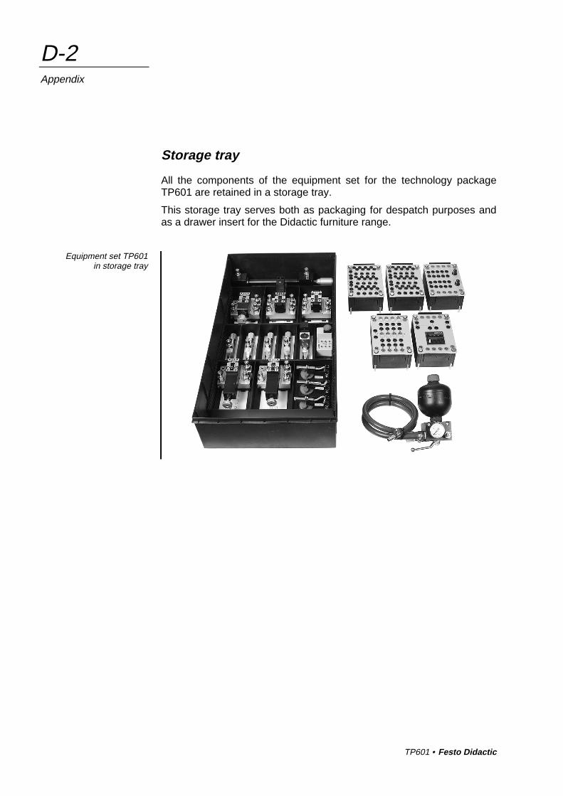
Storage tray
All the components of the equipment set for the technology packageTP601 are retained in a storage tray.
This storage tray serves both as packaging for despatch purposes andas a drawer insert for the Didactic furniture range.
Equipment set TP601in storage tray
TP601 • Festo Didactic
D-3Appendix
Mounting systems
The components of the equipment set are mounted on the Festo Didac-tic profile plate. The profile plate has 14 parallel T-grooves equallyspaced 50 mm apart.
There is a choice of four alternative systems for mounting the compo-nents on the profile plate:
Variant A : Detent system, used without additional devices.Clamping mechanism with lever and springwhich can be moved along the T-groove,for light non-load-bearing components
Variant B : Rotary system, used without additional devices.Grip nut with locking disc and T-head bolt,vertical or horizontal alignment,for medium-weight load-bearing components
Variant C : Screw-in system, used with additional devices.Cheese-head bolt with T-head nut,vertical and horizontal alignment,for heavy load-bearing components or components whichare rarely removed from the profile plate.(Mounting-system variant C is not used in the equipmentset TP 601).
Variant D : Plug-in system, used with adapters.Components with locating pins for plug-in assemblyboards, can be insert in a T-groove,for light non-load-bearing components
The signal input unit and indicator and relay plates can also be mountedin the mounting frame for ER units.
TP601 • Festo Didactic
D-4Appendix
In the case of variant A , a slide engages in the T-groove of the profileplate. This slide is pre-tensioned by a spring. When the blue lever ispressed, the slide is retracted to allow the component to be removedfrom or fitted to the profile plate. Components are aligned with thegroove and can be moved along this.
In the case of variant B , the component is secured to the profile plateby a T-head bolt and a blue grip nut. A locking disc which can be posi-tioned in steps of 90° is used to position the components, allowing theseto be aligned either parallel to or at right angles to the grooves.
After the locking disc has been set to the desired position, the compo-nent is placed on the profile plate. When the grip nut is turned clock-wise, the T-head bolt is turned through 90°in the T-groove by threadfriction. The grip nut is then turned further to clamp the component tothe profile plate.
Variant C is used with heavy components or components which are tobe secured to the profile plate once only or seldom removed. In thiscase, components are secured by means of internal-hex-head bolts andT-head nuts.
In the case of variant D , our well-proven ER units, on plug-in assemblyboards with locating pins on a 50 mm grid pattern, can be attached tothe profile plate by means of adapters. A black plastic adapter is re-quired for each locating pin. The adapters are positioned in the T-grooves at intervals of 50 mm and secured by rotating them through90°. The locating pins of the ER units are then inserted into the holes inthe adapters.
TP601 • Festo Didactic
D-5Appendix
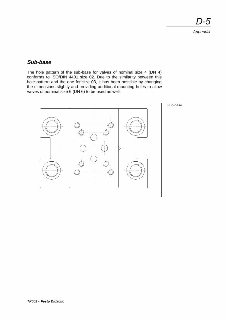
Sub-base
The hole pattern of the sub-base for valves of nominal size 4 (DN 4)conforms to ISO/DIN 4401 size 02. Due to the similarity between thishole pattern and the one for size 03, it has been possible by changingthe dimensions slightly and providing additional mounting holes to allowvalves of nominal size 6 (DN 6) to be used as well.
Sub-base
TP601 • Festo Didactic
D-6Appendix
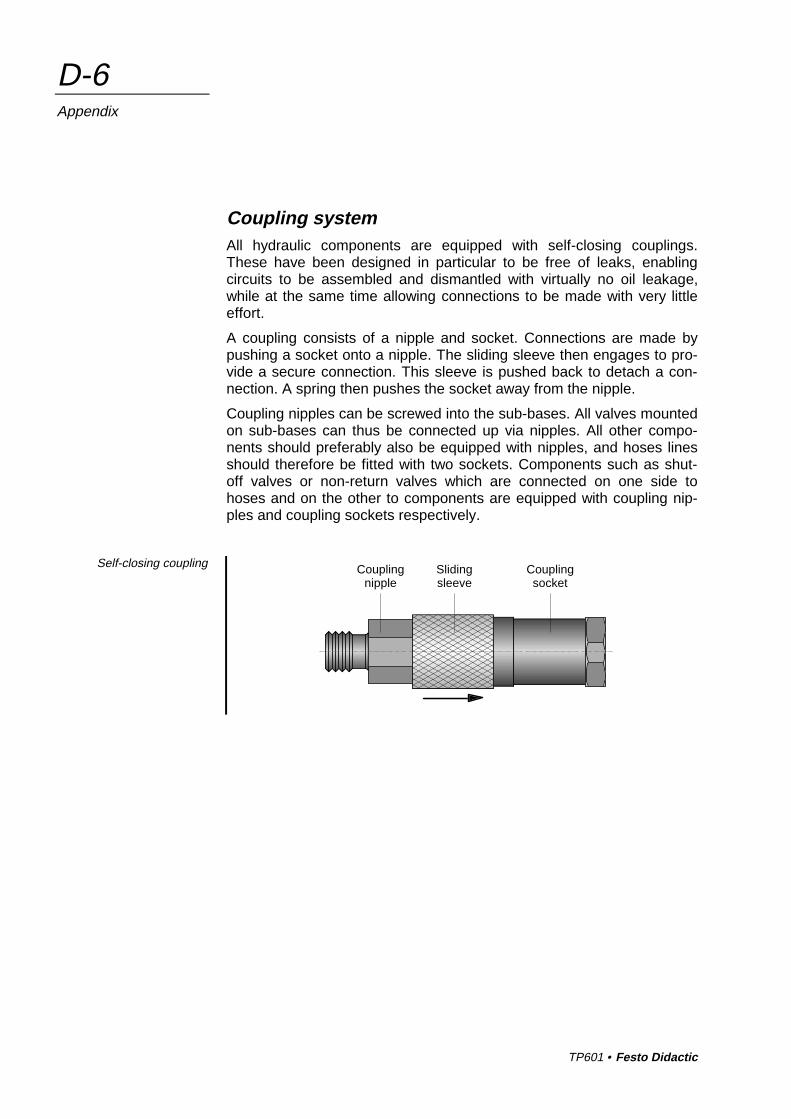
Coupling systemAll hydraulic components are equipped with self-closing couplings.These have been designed in particular to be free of leaks, enablingcircuits to be assembled and dismantled with virtually no oil leakage,while at the same time allowing connections to be made with very littleeffort.
A coupling consists of a nipple and socket. Connections are made bypushing a socket onto a nipple. The sliding sleeve then engages to pro-vide a secure connection. This sleeve is pushed back to detach a con-nection. A spring then pushes the socket away from the nipple.
Coupling nipples can be screwed into the sub-bases. All valves mountedon sub-bases can thus be connected up via nipples. All other compo-nents should preferably also be equipped with nipples, and hoses linesshould therefore be fitted with two sockets. Components such as shut-off valves or non-return valves which are connected on one side tohoses and on the other to components are equipped with coupling nip-ples and coupling sockets respectively.
Self-closing coupling Couplingsocket
Slidingsleeve
Couplingnipple
TP601 • Festo Didactic
D-7Appendix
Since the couplings close to create a leakproof seal, it may occur thatpressure is trapped inside a component. If this happens, the forcerequired to operate the coupling will increase to such an extent that thecomponent cannot subsequently be coupled up again. The remedy incases of this kind is to use a pressure relieving device. This is of similardesign to a coupling socket but incorporates an adjustment spindle. Thespindle should initially be rotated fully out and the device then pushedonto a nipple until the sliding sleeve engages. The spindle can berotated inward to push back the sealing pin of the nipple and open theseal. The pressure behind the nipple will then be relieved; a drop of oilmay escape during this operation. The pressure relieving device can beremoved again by pushing back the sliding sleeve.
The coupling systems consist of the following components:
Description Order No.
Coupling nipple 342 047
Coupling socket 034 649
Pressure relieving device 152 971
TP601 • Festo Didactic
D-8Appendix
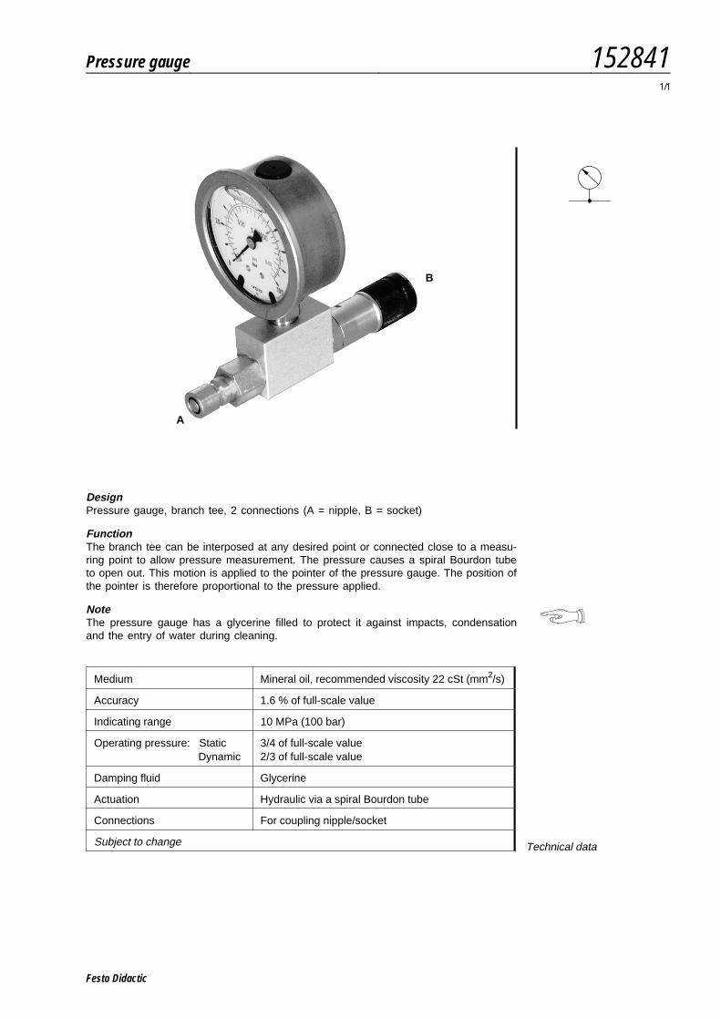
DesignPressure gauge, branch tee, 2 connections (A = nipple, B = socket)
FunctionThe branch tee can be interposed at any desired point or connected close to a measu-ring point to allow pressure measurement. The pressure causes a spiral Bourdon tubeto open out. This motion is applied to the pointer of the pressure gauge. The position ofthe pointer is therefore proportional to the pressure applied.
NoteThe pressure gauge has a glycerine filled to protect it against impacts, condensationand the entry of water during cleaning.
Medium Mineral oil, recommended viscosity 22 cSt (mm2/s)
Accuracy 1.6 % of full-scale value
Indicating range 10 MPa (100 bar)
Operating pressure: StaticDynamic
3/4 of full-scale value2/3 of full-scale value
Damping fluid Glycerine
Actuation Hydraulic via a spiral Bourdon tube
Connections For coupling nipple/socket
Subject to change Technical data
B
A
Pressure gauge 1528411/1
Festo Didactic

Festo Didactic
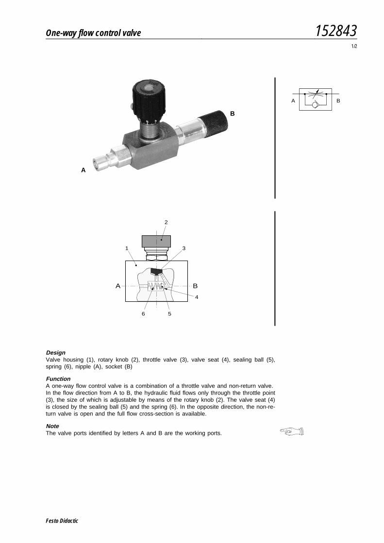
DesignValve housing (1), rotary knob (2), throttle valve (3), valve seat (4), sealing ball (5),spring (6), nipple (A), socket (B)
FunctionA one-way flow control valve is a combination of a throttle valve and non-return valve.In the flow direction from A to B, the hydraulic fluid flows only through the throttle point(3), the size of which is adjustable by means of the rotary knob (2). The valve seat (4)is closed by the sealing ball (5) and the spring (6). In the opposite direction, the non-re-turn valve is open and the full flow cross-section is available.
NoteThe valve ports identified by letters A and B are the working ports.
A B
A
B
1
2
4
5
A B
3
6
One-way flow control valve 1528431/2
Festo Didactic
Medium Mineral oil, recommended viscosity 22 cSt (mm2/s)
Operating pressure p 60 bar (6 MPa)
Max. permissible pressure pmax 120 bar (12 MPa)
Nominal flow rate 9 l/min
Opening pressure 0.7 bar (70 kPa)
Actuation Manual
Connections For coupling nipple/socket
Subject to changeTechnical data
0 1 2 3 4 5 8
0
3
4
5
6
8
p (MPa)
2
1
qV6 (l/min)
1 5 10 15 20 25
ϑ : 46 ˚C
qV
ν : 30 cSt
: A B27
28
30
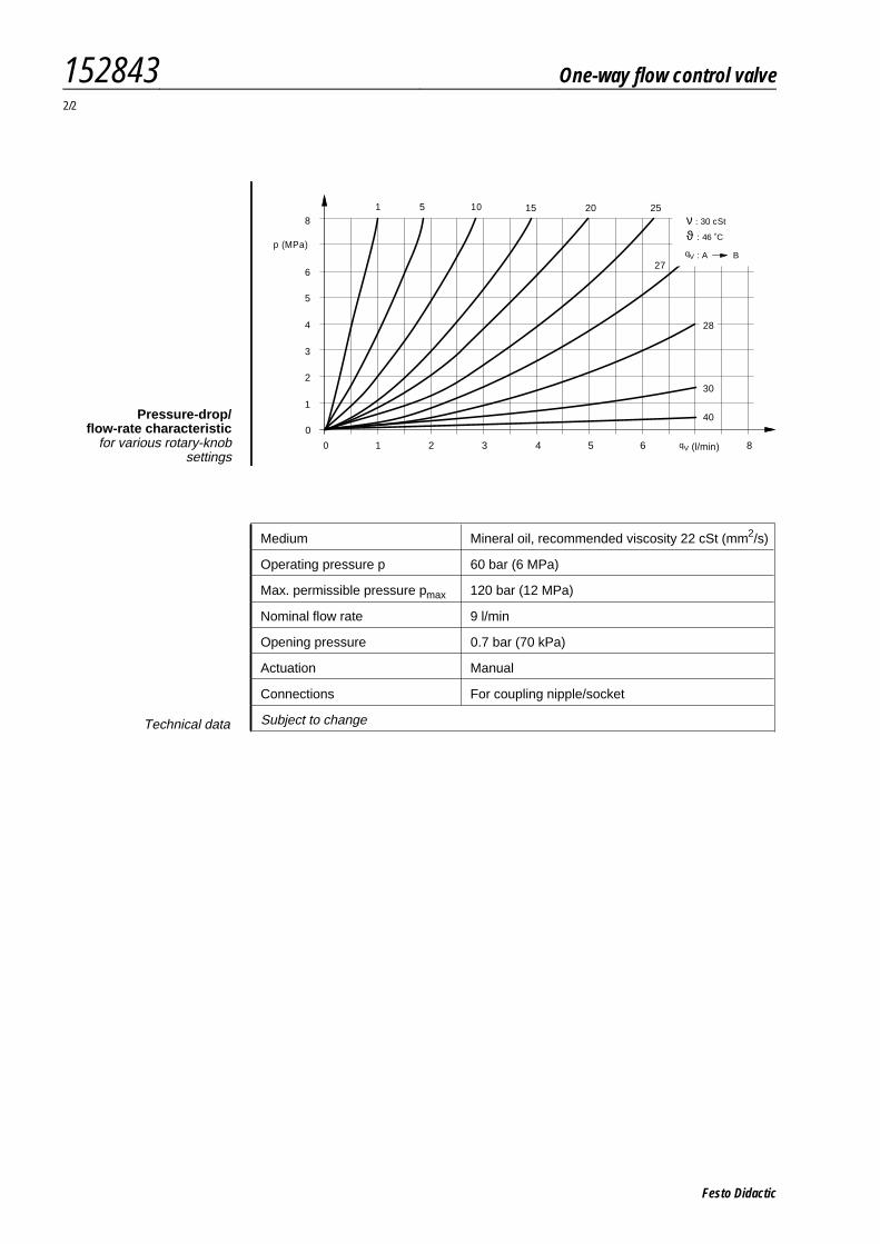
40Pressure-drop/flow-rate characteristic
for various rotary-knobsettings
152843 One-way flow control valve2/2
Festo Didactic
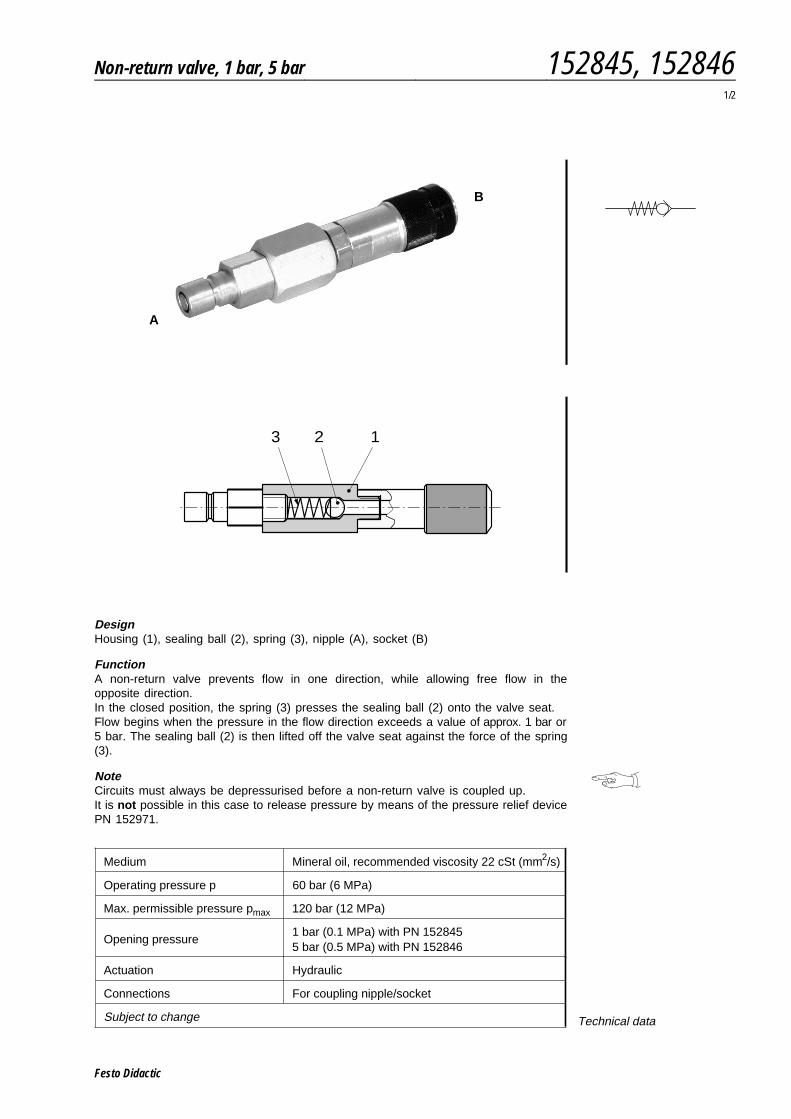
DesignHousing (1), sealing ball (2), spring (3), nipple (A), socket (B)
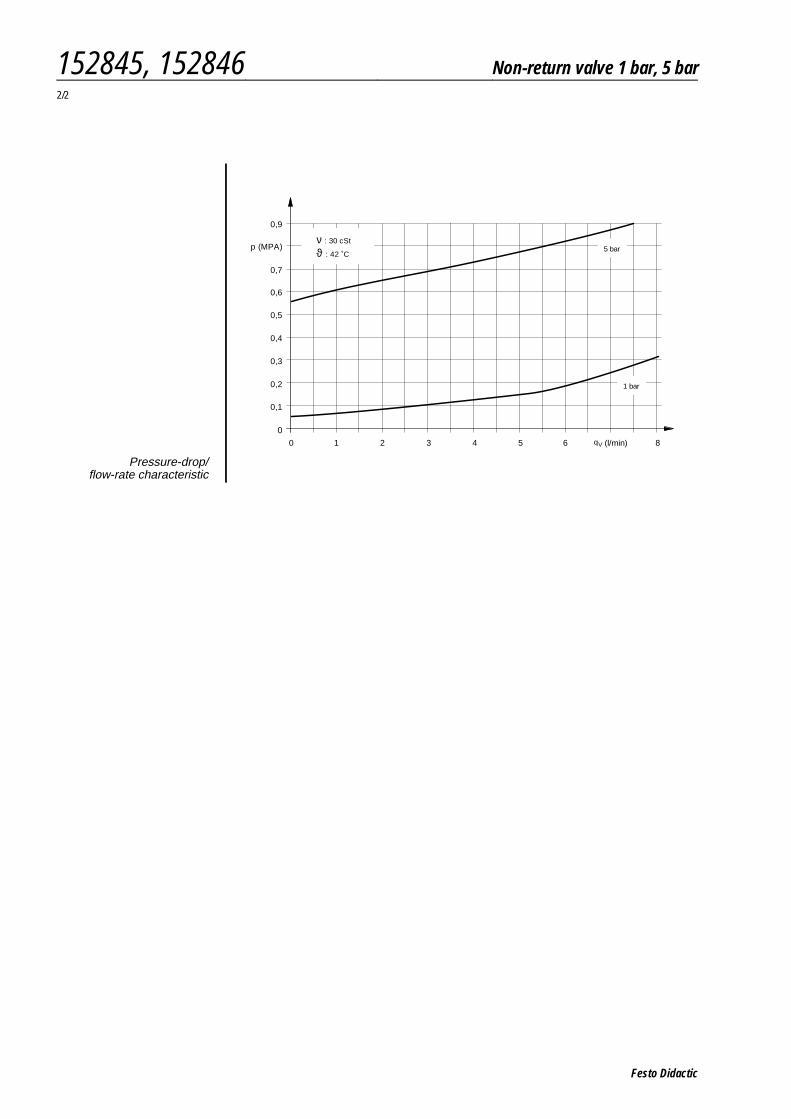
FunctionA non-return valve prevents flow in one direction, while allowing free flow in theopposite direction.In the closed position, the spring (3) presses the sealing ball (2) onto the valve seat.Flow begins when the pressure in the flow direction exceeds a value of approx. 1 bar or5 bar. The sealing ball (2) is then lifted off the valve seat against the force of the spring(3).
NoteCircuits must always be depressurised before a non-return valve is coupled up.It is not possible in this case to release pressure by means of the pressure relief devicePN 152971.
Medium Mineral oil, recommended viscosity 22 cSt (mm2/s)
Operating pressure p 60 bar (6 MPa)
Max. permissible pressure pmax 120 bar (12 MPa)
Opening pressure1 bar (0.1 MPa) with PN 1528455 bar (0.5 MPa) with PN 152846
Actuation Hydraulic
Connections For coupling nipple/socket
Subject to change Technical data
123
B
A
Non-return valve, 1 bar, 5 bar 152845, 1528461/2
Festo Didactic
0 1 2 3 4 5 6 8
0
0,3
0,4
0,6
0,2
0,1
0,5
0,7
0,9
p (MPA) ϑ : 42 ˚C
ν : 30 cSt
(l/min)qV
5 bar
1 bar
Pressure-drop/flow-rate characteristic
152845, 152846 Non-return valve 1 bar, 5 bar2/2
Festo Didactic
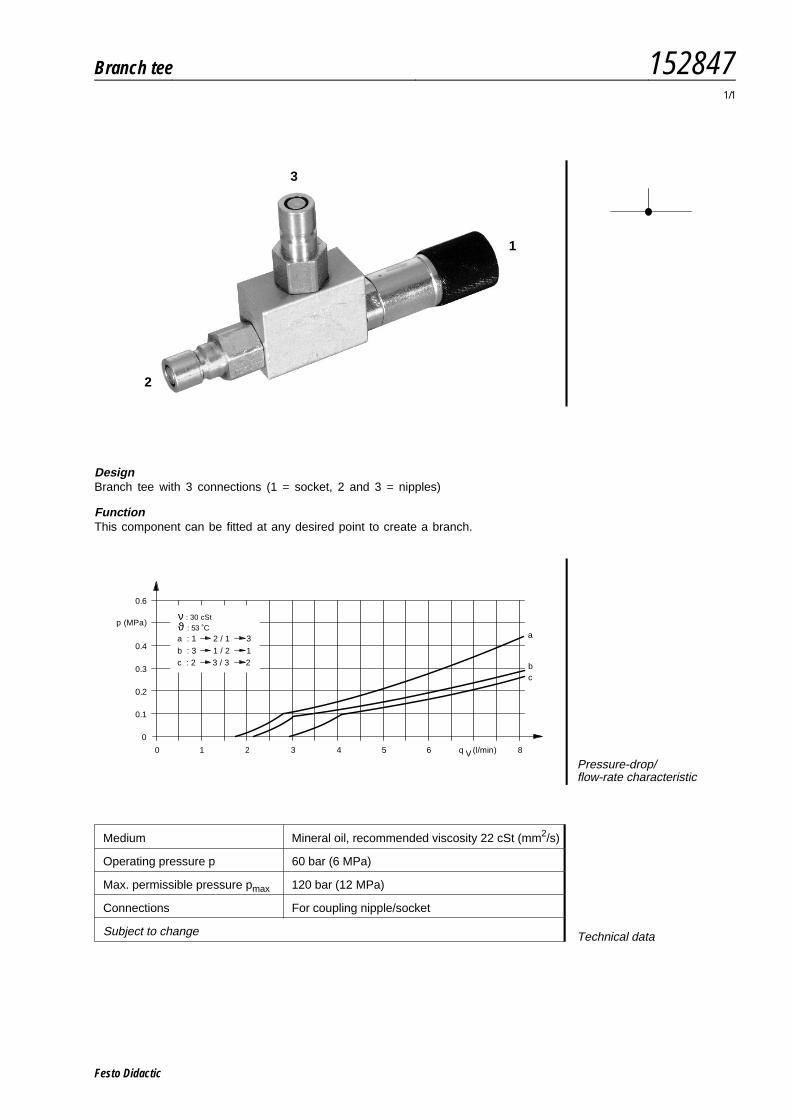
DesignBranch tee with 3 connections (1 = socket, 2 and 3 = nipples)
FunctionThis component can be fitted at any desired point to create a branch.
Medium Mineral oil, recommended viscosity 22 cSt (mm2/s)
Operating pressure p 60 bar (6 MPa)
Max. permissible pressure pmax 120 bar (12 MPa)
Connections For coupling nipple/socket
Subject to change Technical data
1
2
3
0 1 2 3 4 5 6 8
0
0.3
0.4
0.6
q
p (MPa)
0.2
0.1
a : 1 2 / 1 3 a
b : 3 1 / 2 1c : 2 3 / 3 2 b
c
(l/min)V
ϑ : 53 ˚Cν : 30 cSt
Pressure-drop/flow-rate characteristic
Branch tee 1528471/1
Festo Didactic

Festo Didactic
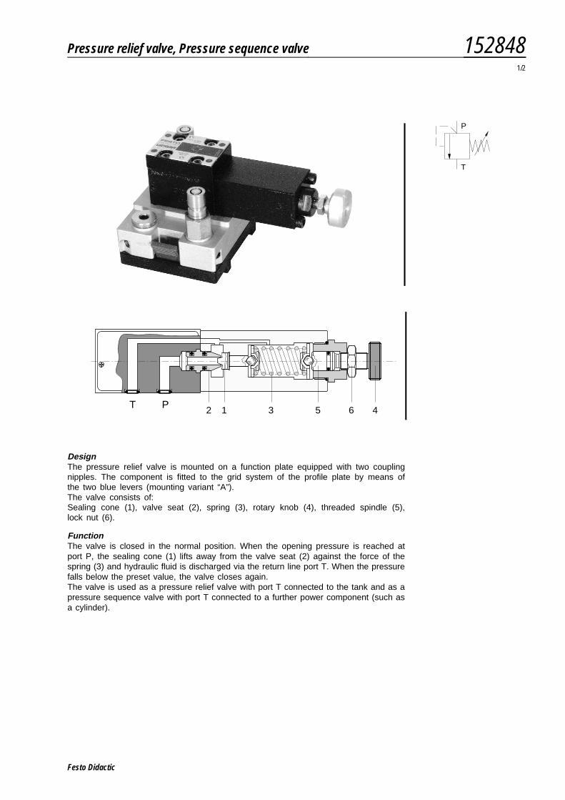
DesignThe pressure relief valve is mounted on a function plate equipped with two couplingnipples. The component is fitted to the grid system of the profile plate by means ofthe two blue levers (mounting variant “A”).The valve consists of:Sealing cone (1), valve seat (2), spring (3), rotary knob (4), threaded spindle (5),lock nut (6).
FunctionThe valve is closed in the normal position. When the opening pressure is reached atport P, the sealing cone (1) lifts away from the valve seat (2) against the force of thespring (3) and hydraulic fluid is discharged via the return line port T. When the pressurefalls below the preset value, the valve closes again.The valve is used as a pressure relief valve with port T connected to the tank and as apressure sequence valve with port T connected to a further power component (such asa cylinder).
P
T
T P2 1 3 5 6 4
Pressure relief valve, Pressure sequence valve 1528481/2
Festo Didactic
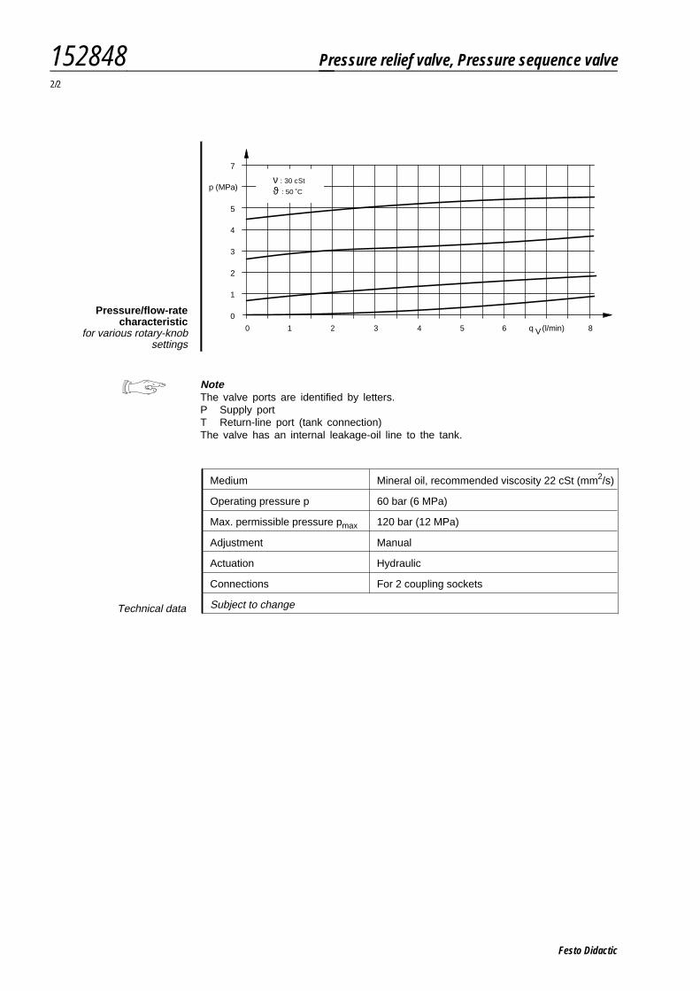
NoteThe valve ports are identified by letters.P Supply portT Return-line port (tank connection)The valve has an internal leakage-oil line to the tank.
Medium Mineral oil, recommended viscosity 22 cSt (mm2/s)
Operating pressure p 60 bar (6 MPa)
Max. permissible pressure pmax 120 bar (12 MPa)
Adjustment Manual
Actuation Hydraulic
Connections For 2 coupling sockets
Subject to changeTechnical data
0 1 2 3 4 5 6 8
0
3
5
p (MPa)
2
1
7
4
q (l/min)V
ϑ : 50 ˚C
ν : 30 cSt
Pressure/flow-ratecharacteristic
for various rotary-knobsettings
152848 Pressure relief valve, Pressure sequence valve2/2
Festo Didactic
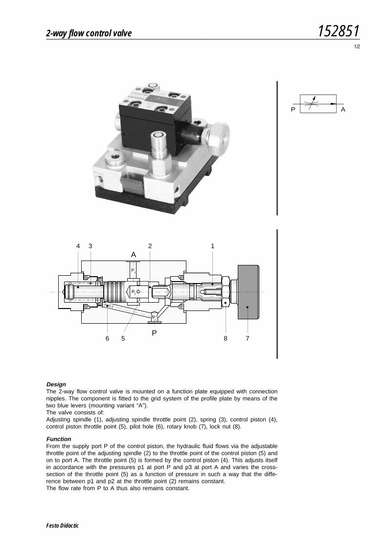
DesignThe 2-way flow control valve is mounted on a function plate equipped with connectionnipples. The component is fitted to the grid system of the profile plate by means of thetwo blue levers (mounting variant “A”).The valve consists of:Adjusting spindle (1), adjusting spindle throttle point (2), spring (3), control piston (4),control piston throttle point (5), pilot hole (6), rotary knob (7), lock nut (8).
FunctionFrom the supply port P of the control piston, the hydraulic fluid flows via the adjustablethrottle point of the adjusting spindle (2) to the throttle point of the control piston (5) andon to port A. The throttle point (5) is formed by the control piston (4). This adjusts itselfin accordance with the pressures p1 at port P and p3 at port A and varies the cross-section of the throttle point (5) as a function of pressure in such a way that the diffe-rence between p1 and p2 at the throttle point (2) remains constant.The flow rate from P to A thus also remains constant.
P A
856
3 2A
P
P3
P2
P1
7
14
2-way flow control valve 1528511/2
Festo Didactic
NoteThe valve ports are identified by letters.P Supply portA Working port
Medium Mineral oil, recommended viscosity 22 cSt (mm2/s)
Operating pressure p 60 bar (6 MPa)
Max. permissible pressure pmax 120 bar (12 MPa)
Adjustment Manual
Actuation Hydraulic
Connections For 2 coupling sockets
Subject to changeTechnical data
0 1.0 2.0 3.0 4.0 5.0 6.0
0
3
4
6
p (MPa)
2
1
0.5 1.5 2.5 3.5 4.5 5.5 7.0
qV (l/min)
ϑ : 43 ˚C
ν : 30 cSt
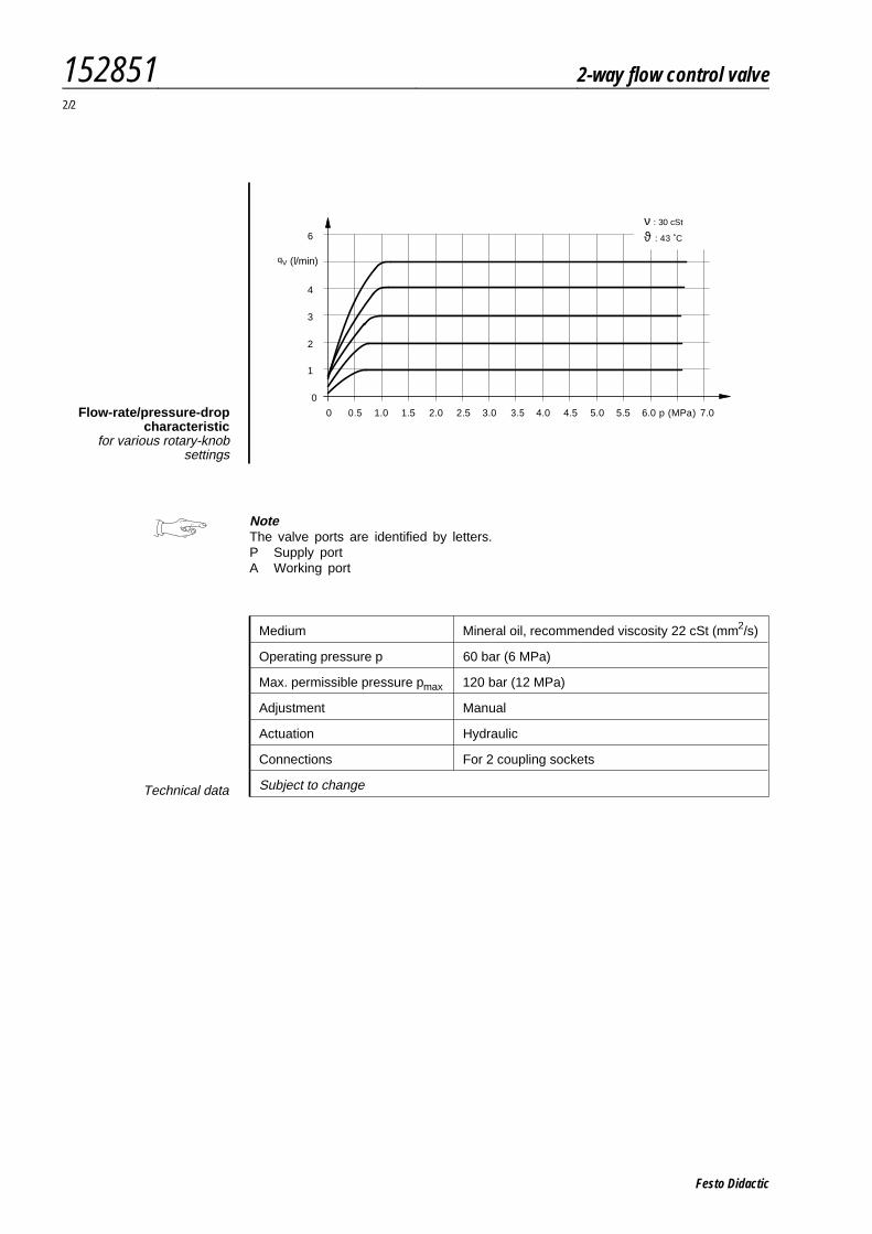
Flow-rate/pressure-dropcharacteristic
for various rotary-knobsettings
152851 2-way flow control valve2/2
Festo Didactic
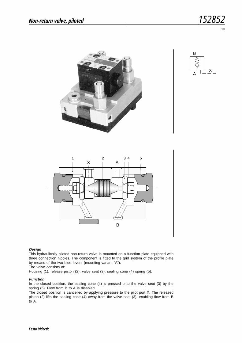
DesignThis hydraulically piloted non-return valve is mounted on a function plate equipped withthree connection nipples. The component is fitted to the grid system of the profile plateby means of the two blue levers (mounting variant “A”).The valve consists of:Housing (1), release piston (2), valve seat (3), sealing cone (4) spring (5).
FunctionIn the closed position, the sealing cone (4) is pressed onto the valve seat (3) by thespring (5). Flow from B to A is disabled.The closed position is cancelled by applying pressure to the pilot port X. The releasedpiston (2) lifts the sealing cone (4) away from the valve seat (3), enabling flow from Bto A.
B
AX
A
B
X1 2 3 4 5
Non-return valve, piloted 1528521/2
Festo Didactic
NoteThe valve ports are identified by letters.A, B Working portsX Pilot port
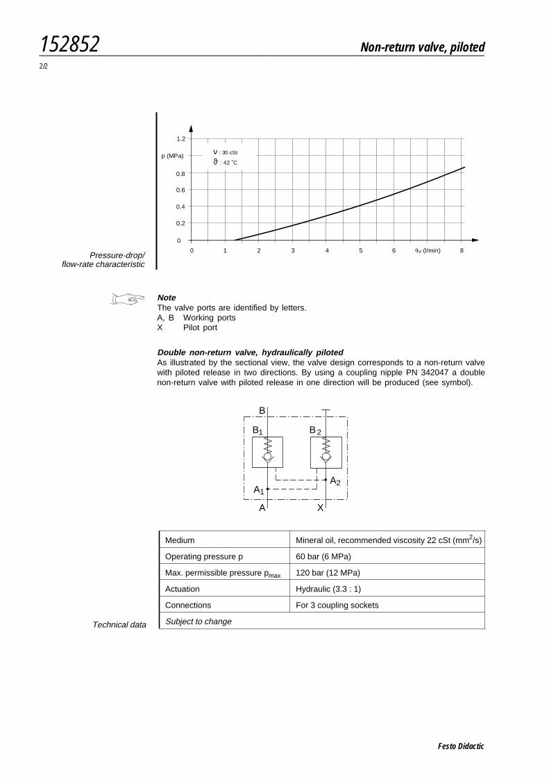
Double non-return valve, hydraulically pilotedAs illustrated by the sectional view, the valve design corresponds to a non-return valvewith piloted release in two directions. By using a coupling nipple PN 342047 a doublenon-return valve with piloted release in one direction will be produced (see symbol).
0 1 2 3 4 5 6 8
0
p (MPa)
0.2
0.4
0.6
0.8
1.2
ϑ : 42 ˚C
ν : 30 cSt
(l/min)qVPressure-drop/
flow-rate characteristic
B
1 2
A1A2
A X
B B
Medium Mineral oil, recommended viscosity 22 cSt (mm2/s)
Operating pressure p 60 bar (6 MPa)
Max. permissible pressure pmax 120 bar (12 MPa)
Actuation Hydraulic (3.3 : 1)
Connections For 3 coupling sockets
Subject to changeTechnical data
152852 Non-return valve, piloted2/2
Festo Didactic
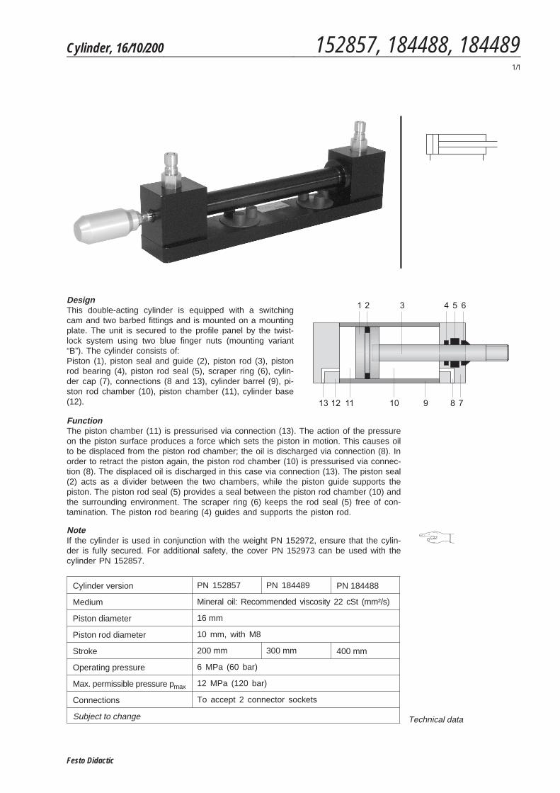
DesignThis double-acting cylinder is equipped with a switchingcam and two barbed fittings and is mounted on a mountingplate. The unit is secured to the profile panel by the twist-lock system using two blue finger nuts (mounting variant“B”). The cylinder consists of:Piston (1), piston seal and guide (2), piston rod (3), pistonrod bearing (4), piston rod seal (5), scraper ring (6), cylin-der cap (7), connections (8 and 13), cylinder barrel (9), pi-ston rod chamber (10), piston chamber (11), cylinder base(12).
FunctionThe piston chamber (11) is pressurised via connection (13). The action of the pressureon the piston surface produces a force which sets the piston in motion. This causes oilto be displaced from the piston rod chamber; the oil is discharged via connection (8). Inorder to retract the piston again, the piston rod chamber (10) is pressurised via connec-tion (8). The displaced oil is discharged in this case via connection (13). The piston seal(2) acts as a divider between the two chambers, while the piston guide supports thepiston. The piston rod seal (5) provides a seal between the piston rod chamber (10) andthe surrounding environment. The scraper ring (6) keeps the rod seal (5) free of con-tamination. The piston rod bearing (4) guides and supports the piston rod.
NoteIf the cylinder is used in conjunction with the weight PN 152972, ensure that the cylin-der is fully secured. For additional safety, the cover PN 152973 can be used with thecylinder PN 152857.
Cylinder version PN 152857 PN 184489 PN 184488
Medium Mineral oil: Recommended viscosity 22 cSt (mm²/s)
Piston diameter 16 mm
Piston rod diameter 10 mm, with M8
Stroke 200 mm 300 mm 400 mm
Operating pressure 6 MPa (60 bar)
Max. permissible pressure pmax 12 MPa (120 bar)
Connections To accept 2 connector sockets
Subject to change Technical data
Cylinder, 16/10/200 152857, 184488, 1844891/1
Festo Didactic

Festo Didactic
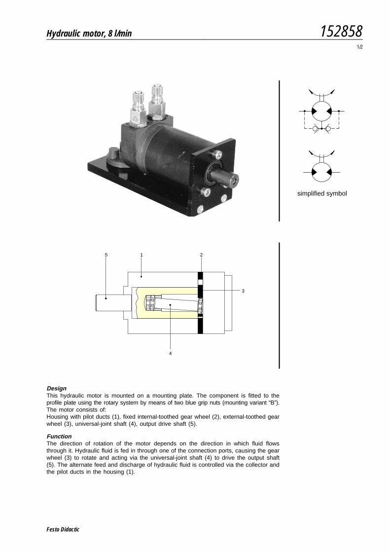
DesignThis hydraulic motor is mounted on a mounting plate. The component is fitted to theprofile plate using the rotary system by means of two blue grip nuts (mounting variant “B”).The motor consists of:Housing with pilot ducts (1), fixed internal-toothed gear wheel (2), external-toothed gearwheel (3), universal-joint shaft (4), output drive shaft (5).
FunctionThe direction of rotation of the motor depends on the direction in which fluid flowsthrough it. Hydraulic fluid is fed in through one of the connection ports, causing the gearwheel (3) to rotate and acting via the universal-joint shaft (4) to drive the output shaft(5). The alternate feed and discharge of hydraulic fluid is controlled via the collector andthe pilot ducts in the housing (1).
vereinfachtes Symbolsimplified symbol
5 1 2
4
3
Hydraulic motor, 8 l/min 1528581/2
Festo Didactic
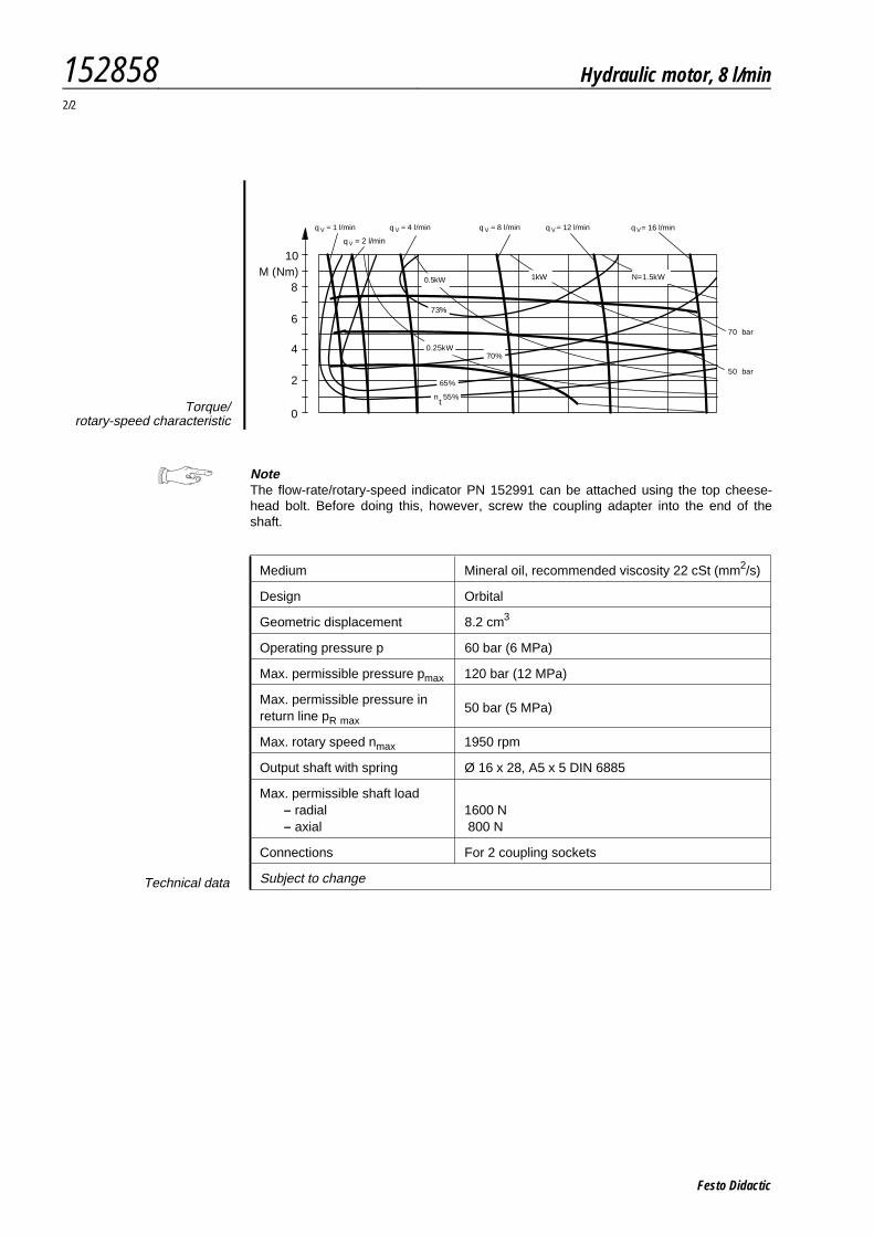
NoteThe flow-rate/rotary-speed indicator PN 152991 can be attached using the top cheese-head bolt. Before doing this, however, screw the coupling adapter into the end of theshaft.
Medium Mineral oil, recommended viscosity 22 cSt (mm2/s)
Design Orbital
Geometric displacement 8.2 cm3
Operating pressure p 60 bar (6 MPa)
Max. permissible pressure pmax 120 bar (12 MPa)
Max. permissible pressure inreturn line pR max
50 bar (5 MPa)
Max. rotary speed nmax 1950 rpm
Output shaft with spring Ø 16 x 28, A5 x 5 DIN 6885
Max. permissible shaft load– radial– axial
1600 N800 N
Connections For 2 coupling sockets
Subject to changeTechnical data
0
2
4
6
8
10
= 1 l/min
= 2 l/min
= 4 l/min = 8 l/min = 12 l/min = 16 l/min
0.5kW
0.25kW
1kW N=1.5kW
73%
70%
65%
n 55%t
70 bar
50 bar
M (Nm)
Vq Vq
Vq
Vq Vq Vq
Torque/rotary-speed characteristic
152858 Hydraulic motor, 8 l/min2/2
Festo Didactic
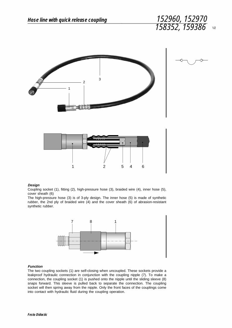
DesignCoupling socket (1), fitting (2), high-pressure hose (3), braided wire (4), inner hose (5),cover sheath (6)The high-pressure hose (3) is of 3-ply design. The inner hose (5) is made of syntheticrubber, the 2nd ply of braided wire (4) and the cover sheath (6) of abrasion-resistantsynthetic rubber.
FunctionThe two coupling sockets (1) are self-closing when uncoupled. These sockets provide aleakproof hydraulic connection in conjunction with the coupling nipple (7). To make aconnection, the coupling socket (1) is pushed onto the nipple until the sliding sleeve (8)snaps forward. This sleeve is pulled back to separate the connection. The couplingsocket will then spring away from the nipple. Only the front faces of the couplings comeinto contact with hydraulic fluid during the coupling operation.
23
1
1 2 4 65
7 8 1
Hose line with quick release coupling 152960, 152970158352, 159386 1/2
Festo Didactic
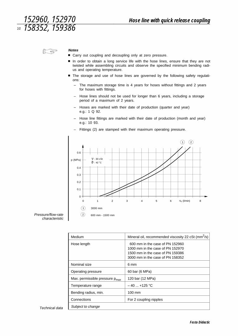
Notes■ Carry out coupling and decoupling only at zero pressure.
■ In order to obtain a long service life with the hose lines, ensure that they are nottwisted while assembling circuits and observe the specified minimum bending radi-us and operating temperature.
■ The storage and use of hose lines are governed by the following safety regulati-ons:– The maximum storage time is 4 years for hoses without fittings and 2 years
for hoses with fittings.
– Hose lines should not be used for longer than 6 years, including a storageperiod of a maximum of 2 years.
– Hoses are marked with their date of production (quarter and year)e.g.: 1 Q 92.
– Hose line fittings are marked with their date of production (month and year)e.g.: 10 93.
– Fittings (2) are stamped with their maximum operating pressure.
Medium Mineral oil, recommended viscosity 22 cSt (mm2/s)
Hose length 600 mm in the case of PN 1529601000 mm in the case of PN 1529701500 mm in the case of PN 1593863000 mm in the case of PN 158352
Nominal size 6 mm
Operating pressure 60 bar (6 MPa)
Max. permissible pressure pmax 120 bar (12 MPa)
Temperature range – 40 ... +125 °C
Bending radius, min. 100 mm
Connections For 2 coupling nipples
Subject to changeTechnical data
0 1 2 3 4 5 6 8
0
p (MPa)
0.1
0.2
0.3
0.4
0.6
1 2
1
2
3000 mm
600 mm - 1500 mm
ϑ : 42 ˚C
ν : 30 cSt
(l/min)qV
Pressure/flow-ratecharacteristic
152960, 152970 Hose line with quick release coupling2/2 158352, 159386
Festo Didactic
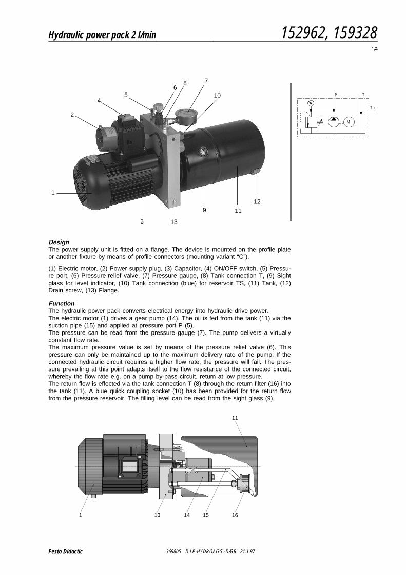
DesignThe power supply unit is fitted on a flange. The device is mounted on the profile plateor another fixture by means of profile connectors (mounting variant “C”).
(1) Electric motor, (2) Power supply plug, (3) Capacitor, (4) ON/OFF switch, (5) Pressu-re port, (6) Pressure-relief valve, (7) Pressure gauge, (8) Tank connection T, (9) Sightglass for level indicator, (10) Tank connection (blue) for reservoir TS, (11) Tank, (12)Drain screw, (13) Flange.
FunctionThe hydraulic power pack converts electrical energy into hydraulic drive power.The electric motor (1) drives a gear pump (14). The oil is fed from the tank (11) via thesuction pipe (15) and applied at pressure port P (5).The pressure can be read from the pressure gauge (7). The pump delivers a virtuallyconstant flow rate.The maximum pressure value is set by means of the pressure relief valve (6). Thispressure can only be maintained up to the maximum delivery rate of the pump. If theconnected hydraulic circuit requires a higher flow rate, the pressure will fail. The pres-sure prevailing at this point adapts itself to the flow resistance of the connected circuit,whereby the flow rate e.g. on a pump by-pass circuit, return at low pressure.The return flow is effected via the tank connection T (8) through the return filter (16) intothe tank (11). A blue quick coupling socket (10) has been provided for the return flowfrom the pressure reservoir. The filling level can be read from the sight glass (9).
P T
T s
M
1
2
3
45
678
9
10
11
12
13
369805 D.LP-HYDROAGG.-D/GB 21.1.97
1 13 14 16
11
15
Hydraulic power pack 2 l/min 152962, 1593281/4
Festo Didactic
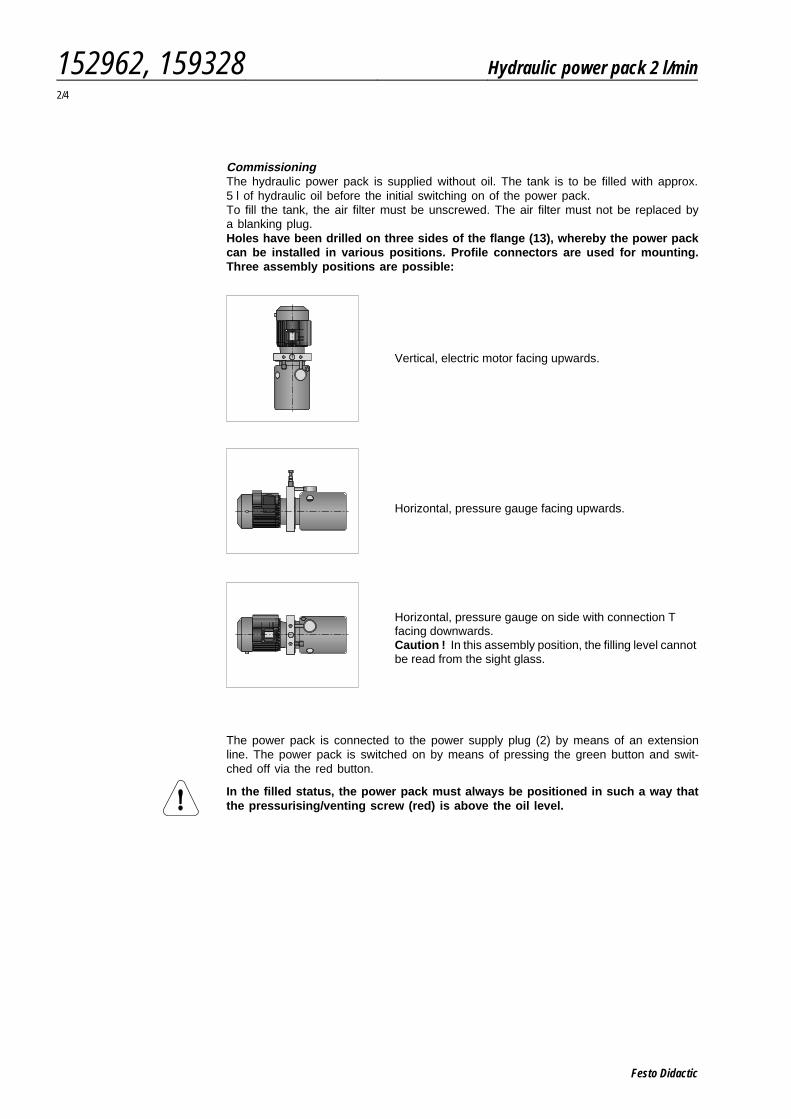
CommissioningThe hydraulic power pack is supplied without oil. The tank is to be filled with approx.5 l of hydraulic oil before the initial switching on of the power pack.To fill the tank, the air filter must be unscrewed. The air filter must not be replaced bya blanking plug.Holes have been drilled on three sides of the flange (13), whereby the power packcan be installed in various positions. Profile connectors are used for mounting.Three assembly positions are possible:
The power pack is connected to the power supply plug (2) by means of an extensionline. The power pack is switched on by means of pressing the green button and swit-ched off via the red button.
In the filled status, the power pack must always be positioned in such a way thatthe pressurising/venting screw (red) is above the oil level.
Vertical, electric motor facing upwards.
Horizontal, pressure gauge facing upwards.
Horizontal, pressure gauge on side with connection Tfacing downwards.Caution ! In this assembly position, the filling level cannotbe read from the sight glass.
152962, 159328 Hydraulic power pack 2 l/min2/4
Festo Didactic
Notes
■ The power pack must be operated using the pressurising/venting screw (red).Caution! Failing this, the tank may burst.
■ Regularly check the oil level. The pump must not run dry.
■ If an initial start-up of devices takes place, the oil level in the tank is reduced asa result of the displacement. If the oil level can no longer be seen in the sightglass (9), the hydraulic oil must be topped up until the level is visible.
■ The power pack is designed for a 50% duty cycle. If continuous operation is re-quired, an external oil cooler is to be used.
■ If the thermostatic switch of the electric motor is triggered, the red “off” switchmust be actuated after a cooling phase and after checking and eliminating thecause. Normal operation can be re-started following this.
■ The hydraulic power pack is not suitable for the connection of a flow measuringcontainer Pt. No. 162344.
■ If the hydraulic power pack is moved, carried or transported on a trolley, this canlead to sloshing in the tank. This may cause a small quantity of oil to escape viathe air filter.If the hydraulic power pack is incorrectly installed, whereby the air filter is belowthe oil level, the tank will discharge, added to which the pump may run dry.
■ An increase in the flow rate by means of interconnecting several hydraulic powerpacks is not feasible, since it is not possible to compensate the various fillinglevels inside the tanks.
Hydraulic power pack 2 l/min 152962, 1593283/4
Festo Didactic
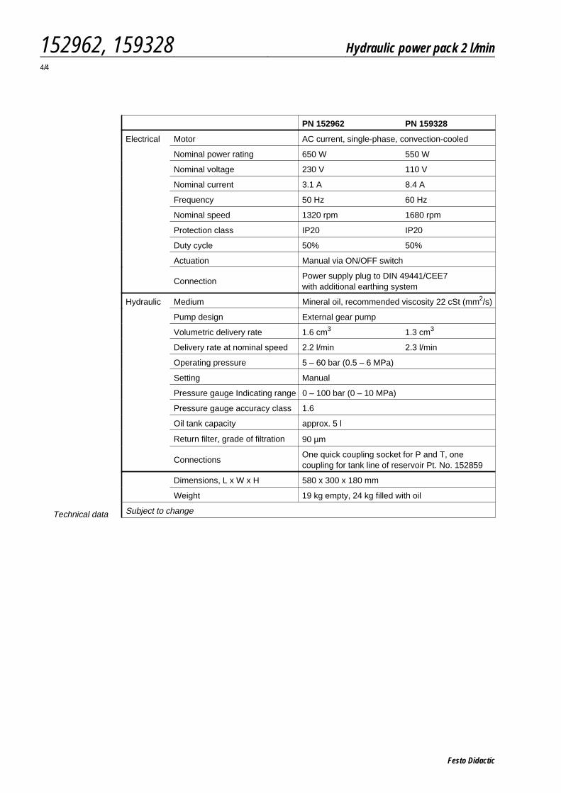
PN 152962 PN 159328
Electrical Motor AC current, single-phase, convection-cooled
Nominal power rating 650 W 550 W
Nominal voltage 230 V 110 V
Nominal current 3.1 A 8.4 A
Frequency 50 Hz 60 Hz
Nominal speed 1320 rpm 1680 rpm
Protection class IP20 IP20
Duty cycle 50% 50%
Actuation Manual via ON/OFF switch
ConnectionPower supply plug to DIN 49441/CEE7with additional earthing system
Hydraulic Medium Mineral oil, recommended viscosity 22 cSt (mm2/s)
Pump design External gear pump
Volumetric delivery rate 1.6 cm3 1.3 cm3
Delivery rate at nominal speed 2.2 l/min 2.3 l/min
Operating pressure 5 – 60 bar (0.5 – 6 MPa)
Setting Manual
Pressure gauge Indicating range 0 – 100 bar (0 – 10 MPa)
Pressure gauge accuracy class 1.6
Oil tank capacity approx. 5 l
Return filter, grade of filtration 90 µm
ConnectionsOne quick coupling socket for P and T, onecoupling for tank line of reservoir Pt. No. 152859
Dimensions, L x W x H 580 x 300 x 180 mm
Weight 19 kg empty, 24 kg filled with oil
Subject to changeTechnical data
152962, 159328 Hydraulic power pack 2 l/min4/4
Festo Didactic
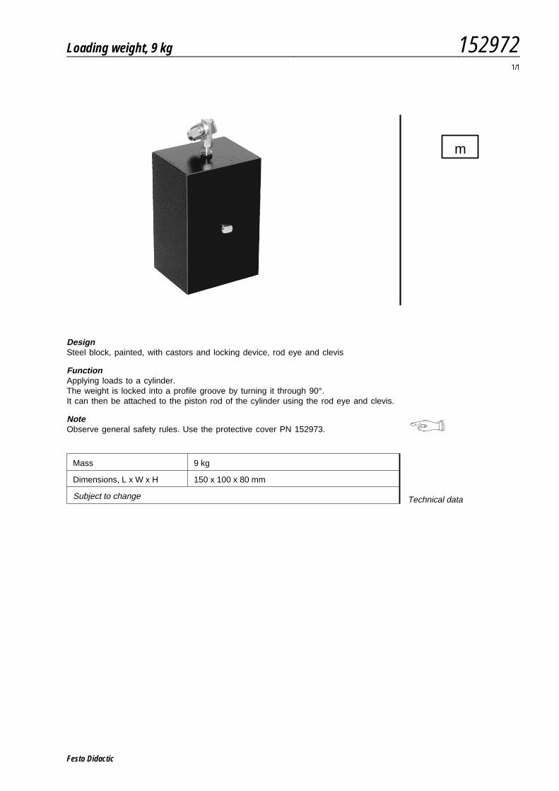
DesignSteel block, painted, with castors and locking device, rod eye and clevis
FunctionApplying loads to a cylinder.The weight is locked into a profile groove by turning it through 90°.It can then be attached to the piston rod of the cylinder using the rod eye and clevis.
NoteObserve general safety rules. Use the protective cover PN 152973.
Mass 9 kg
Dimensions, L x W x H 150 x 100 x 80 mm
Subject to change Technical data
m
Loading weight, 9 kg 1529721/1
Festo Didactic

Festo Didactic
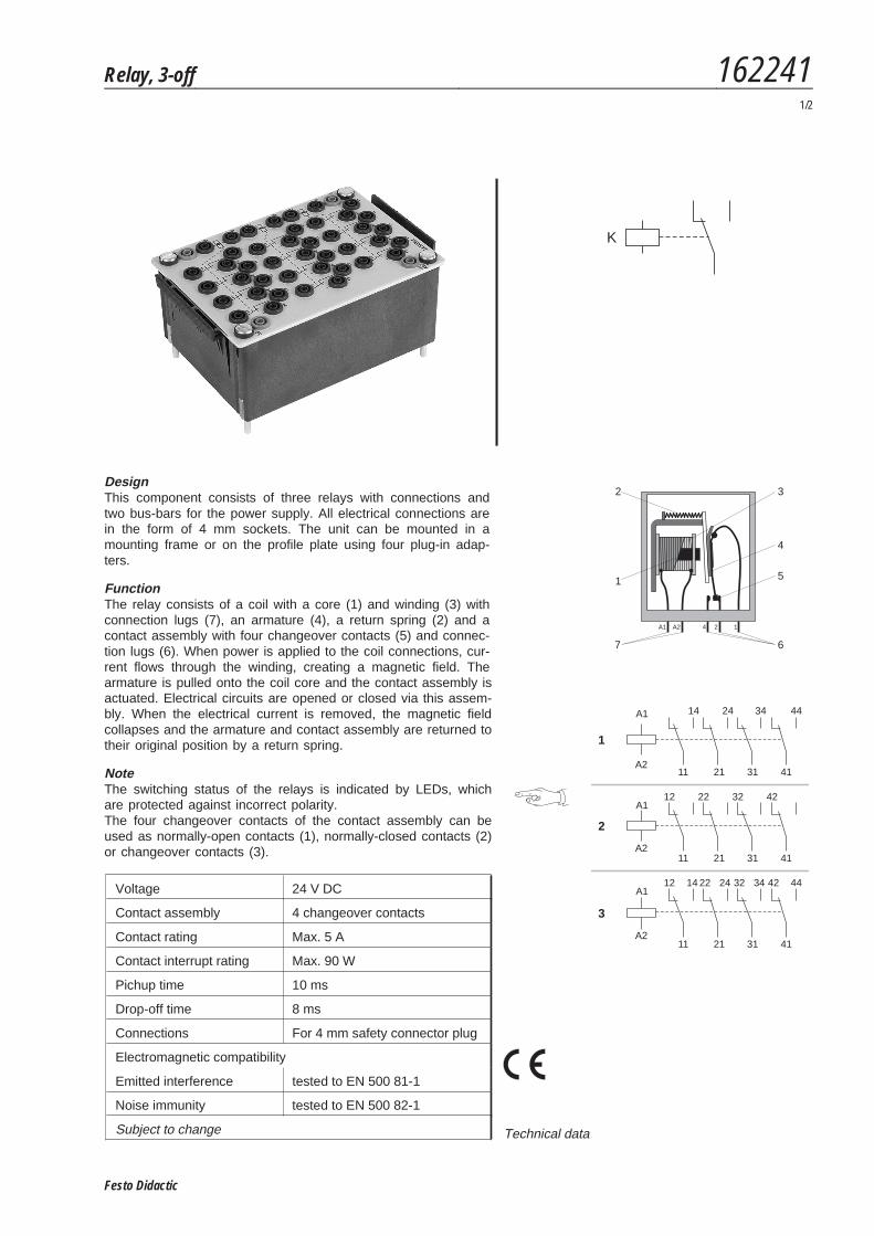
DesignThis component consists of three relays with connections andtwo bus-bars for the power supply. All electrical connections arein the form of 4 mm sockets. The unit can be mounted in amounting frame or on the profile plate using four plug-in adap-ters.
FunctionThe relay consists of a coil with a core (1) and winding (3) withconnection lugs (7), an armature (4), a return spring (2) and acontact assembly with four changeover contacts (5) and connec-tion lugs (6). When power is applied to the coil connections, cur-rent flows through the winding, creating a magnetic field. Thearmature is pulled onto the coil core and the contact assembly isactuated. Electrical circuits are opened or closed via this assem-bly. When the electrical current is removed, the magnetic fieldcollapses and the armature and contact assembly are returned totheir original position by a return spring.
NoteThe switching status of the relays is indicated by LEDs, whichare protected against incorrect polarity.The four changeover contacts of the contact assembly can beused as normally-open contacts (1), normally-closed contacts (2)or changeover contacts (3).
K
1
2
5
67
4
3
124A1 A2
A1
A2
14 24 34 44
11 21 31 41
12 22 32 42
12 14 22 24 32 34 42
1
2
3
A1
A2
A1
A2
11 21 31 41
11 21 31 41
44Voltage 24 V DC
Contact assembly 4 changeover contacts
Contact rating Max. 5 A
Contact interrupt rating Max. 90 W
Pichup time 10 ms
Drop-off time 8 ms
Connections For 4 mm safety connector plug
Electromagnetic compatibility
Emitted interference tested to EN 500 81-1
Noise immunity tested to EN 500 82-1
Subject to change Technical data
Relay, 3-off 1622411/2
Festo Didactic
S
+
_
K
K Y
1 2
2= Öffner
= Schließer
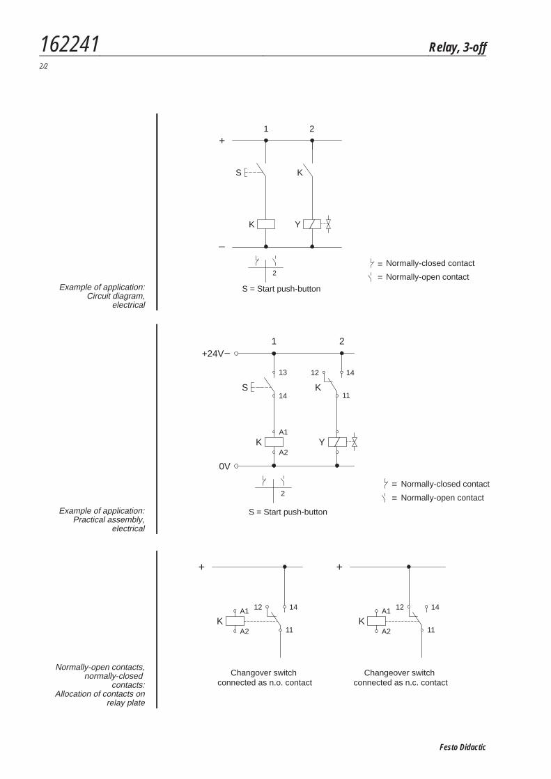
S = START - TasterExample of application:
Circuit diagram,electrical
S
+24V_
0V
K
K Y
1 2
2= Öffner
= Schließer
S = START - Taster
12 14
11
A1
A2
13
14
Example of application:Practical assembly,
electrical
K KA1 A1
A2 A2
+ +
Wechsler als Schließerangeschlossen
Wechsler als Öffnerangeschlossen
12 1214 14
11 11
Normally-open contacts,normally-closed
contacts:Allocation of contacts on
relay plate
Changeover switchconnected as n.c. contact
S = Start push-button
S = Start push-button
Normally-closed contact
Normally-open contact
Normally-closed contact
Normally-open contact
Changover switchconnected as n.o. contact
162241 Relay, 3-off2/2
Festo Didactic
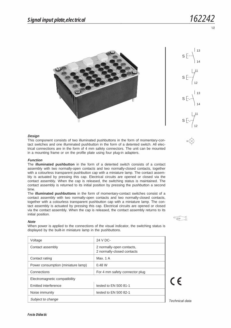
DesignThis component consists of two illuminated pushbuttons in the form of momentary-con-tact switches and one illuminated pushbutton in the form of a detented switch. All elec-trical connections are in the form of 4 mm safety connectors. The unit can be mountedin a mounting frame or on the profile plate using four plug-in adapters.
FunctionThe illuminated pushbutton in the form of a detented switch consists of a contactassembly with two normally-open contacts and two normally-closed contacts, togetherwith a colourless transparent pushbutton cap with a miniature lamp. The contact assem-bly is actuated by pressing this cap. Electrical circuits are opened or closed via thecontact assembly. When the cap is released, the switching status is maintained. Thecontact assembly is returned to its initial position by pressing the pushbutton a secondtime.The illuminated pushbuttons in the form of momentary-contact switches consist of acontact assembly with two normally-open contacts and two normally-closed contacts,together with a colourless transparent pushbutton cap with a miniature lamp. The con-tact assembly is actuated by pressing this cap. Electrical circuits are opened or closedvia the contact assembly. When the cap is released, the contact assembly returns to itsinitial position.
NoteWhen power is applied to the connections of the visual indicator, the switching status isdisplayed by the built-in miniature lamp in the pushbuttons.
Voltage 24 V DC-
Contact assembly 2 normally-open contacts,2 normally-closed contacts
Contact rating Max. 1 A
Power consumption (miniature lamp) 0.48 W
Connections For 4 mm safety connector plug
Electromagnetic compatibility
Emitted interference tested to EN 500 81-1
Noise immunity tested to EN 500 82-1
Subject to change Technical data
S
11
12
S
13
14
S
11
12
S
13
14
H
Signal input plate,electrical 1622421/2
Festo Didactic
S
+
_
K
K Y
1 2
2= Öffner
= Schließer
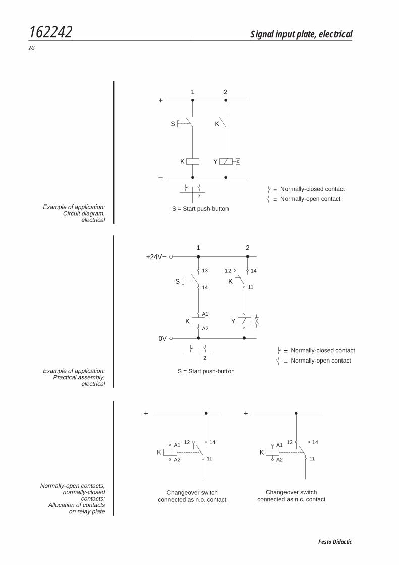
S = START - TasterExample of application:
Circuit diagram,electrical
S
+24V_
0V
K
K Y
1 2
2= Öffner
= Schließer
S = START - Taster
12 14
11
A1
A2
13
14
S = Start push-button
Example of application:Practical assembly,
electrical
K KA1 A1
A2 A2
+ +
Wechsler als Schließerangeschlossen
Wechsler als Öffnerangeschlossen
12 1214 14
11 11
Normally-open contacts,normally-closed
contacts:Allocation of contacts
on relay plate
S = Start push-button
Normally-closed contact
Normally-open contact
Normally-closed contact
Normally-open contact
Changeover switchconnected as n.c. contact
Changeover switchconnected as n.o. contact
162242 Signal input plate, electrical2/2
Festo Didactic
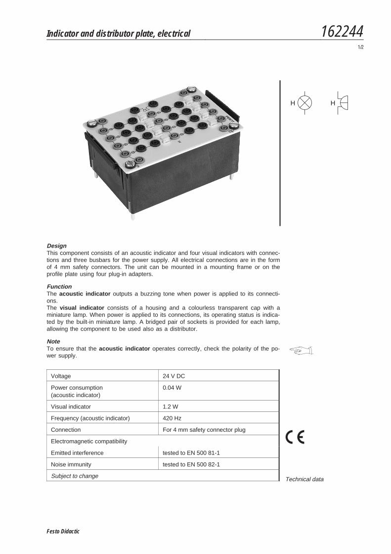
DesignThis component consists of an acoustic indicator and four visual indicators with connec-tions and three busbars for the power supply. All electrical connections are in the formof 4 mm safety connectors. The unit can be mounted in a mounting frame or on theprofile plate using four plug-in adapters.
FunctionThe acoustic indicator outputs a buzzing tone when power is applied to its connecti-ons.The visual indicator consists of a housing and a colourless transparent cap with aminiature lamp. When power is applied to its connections, its operating status is indica-ted by the built-in miniature lamp. A bridged pair of sockets is provided for each lamp,allowing the component to be used also as a distributor.
NoteTo ensure that the acoustic indicator operates correctly, check the polarity of the po-wer supply.
Voltage 24 V DC
Power consumption(acoustic indicator)
0.04 W
Visual indicator 1.2 W
Frequency (acoustic indicator) 420 Hz
Connection For 4 mm safety connector plug
Electromagnetic compatibility
Emitted interference tested to EN 500 81-1
Noise immunity tested to EN 500 82-1
Subject to change Technical data
H H
Indicator and distributor plate, electrical 1622441/2
Festo Didactic
S
+
_
K
K Y H1 H2
1 2 3 4
2= Öffner
= Schließer
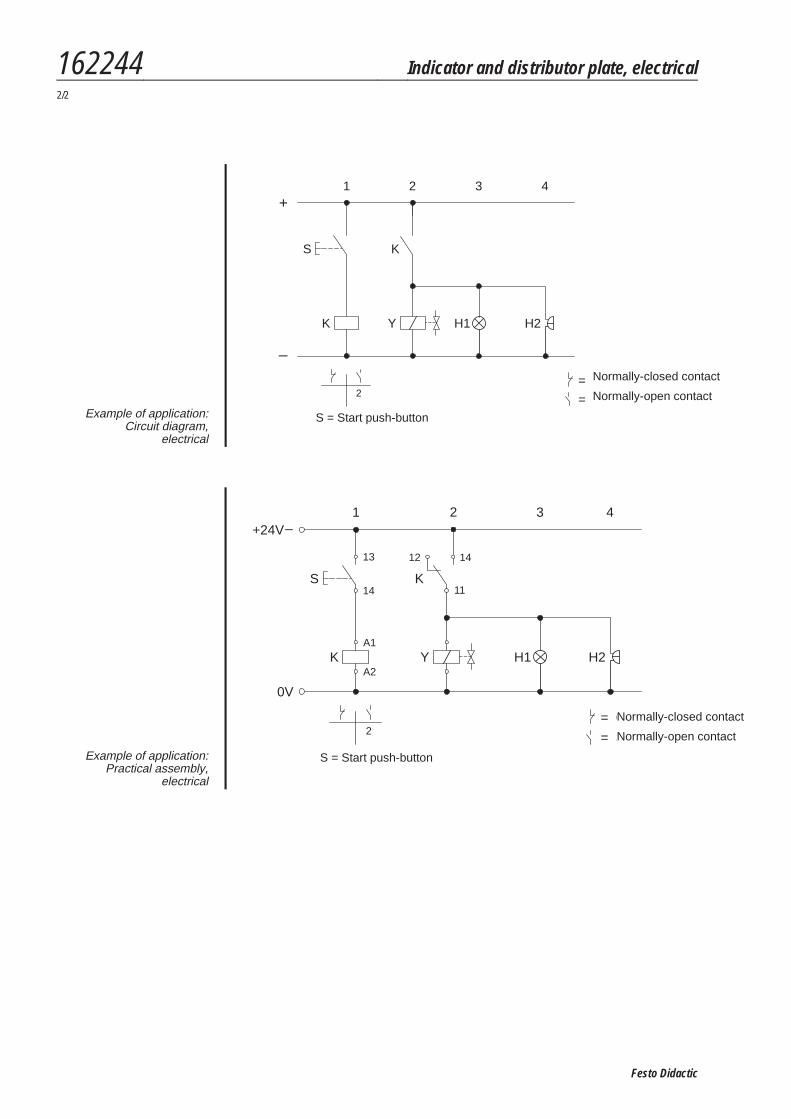
S = START - TasterExample of application:
Circuit diagram,electrical
0V
S
K H1 H2
1 3 4
2= Öffner
= Schließer
S = START - Taster
+24V_
K
Y
2
12 14
11
A1
A2
13
14
Example of application:Practical assembly,
electrical
S = Start push-button
Normally-closed contact
Normally-open contact
Normally-closed contact
Normally-open contact
S = Start push-button
162244 Indicator and distributor plate, electrical2/2
Festo Didactic
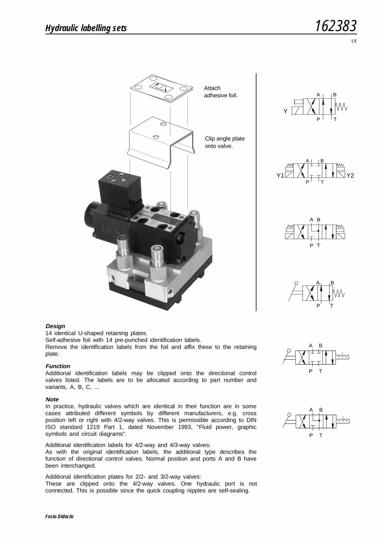
Design14 identical U-shaped retaining plates.Self-adhesive foil with 14 pre-punched identification labels.Remove the identification labels from the foil and affix these to the retainingplate.
FunctionAdditional identification labels may be clipped onto the directional controlvalves listed. The labels are to be allocated according to part number andvariants, A, B, C, ...
NoteIn practice, hydraulic valves which are identical in their function are in somecases attributed different symbols by different manufacturers, e.g. crossposition left or right with 4/2-way valves. This is permissible according to DINISO standard 1219 Part 1, dated November 1993, "Fluid power, graphicsymbols and circuit diagrams".
Additional identification labels for 4/2-way and 4/3-way valves:As with the original identification labels, the additional type describes thefunction of directional control valves. Normal position and ports A and B havebeen interchanged.
Additional identification plates for 2/2- and 3/2-way valves:These are clipped onto the 4/2-way valves. One hydraulic port is notconnected. This is possible since the quick coupling nipples are self-sealing.
Y
A B
P T
Y1
A B
P TY2
A B
P T
Attach adhesive foil.
Clip angle plateonto valve.
A B
P T
A B
P T
A B
P T
Hydraulic labelling sets 1623831/1
Festo Didactic

Festo Didactic
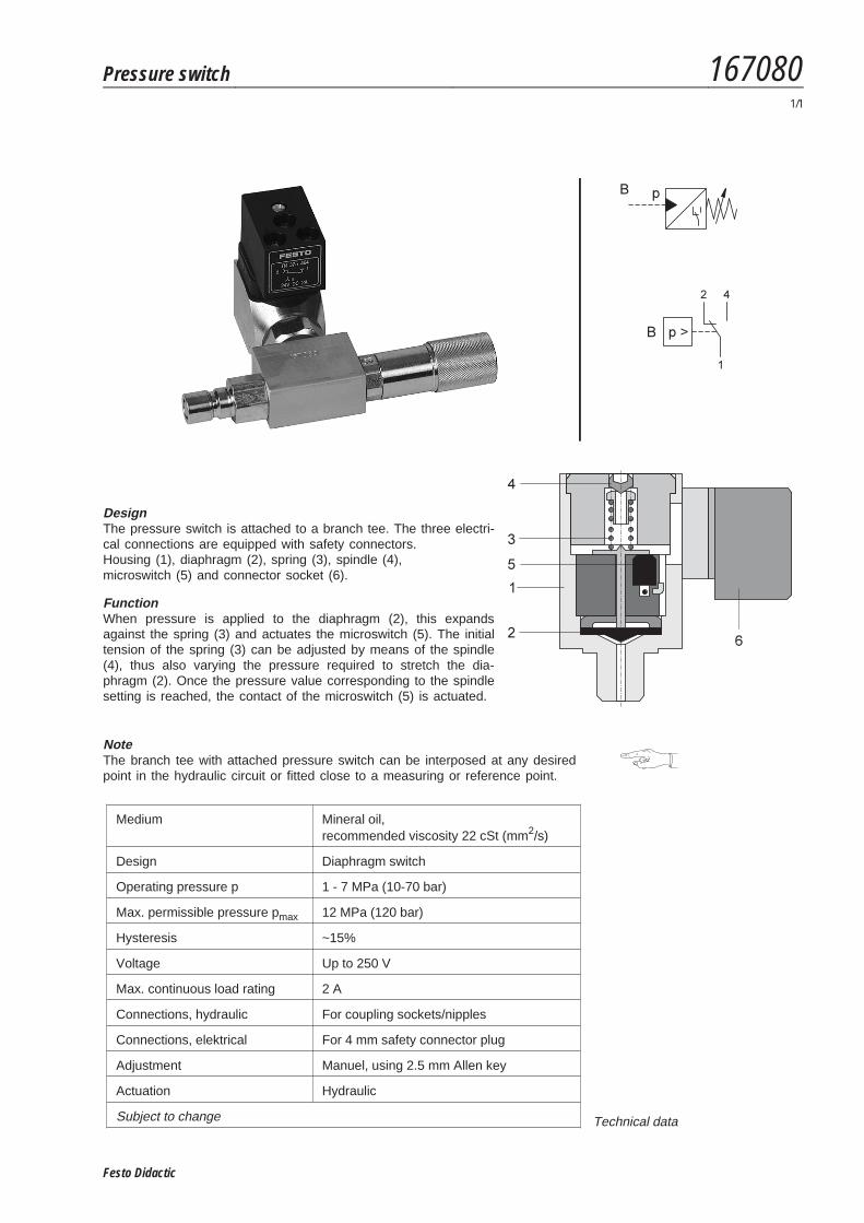
DesignThe pressure switch is attached to a branch tee. The three electri-cal connections are equipped with safety connectors.Housing (1), diaphragm (2), spring (3), spindle (4),microswitch (5) and connector socket (6).
FunctionWhen pressure is applied to the diaphragm (2), this expandsagainst the spring (3) and actuates the microswitch (5). The initialtension of the spring (3) can be adjusted by means of the spindle(4), thus also varying the pressure required to stretch the dia-phragm (2). Once the pressure value corresponding to the spindlesetting is reached, the contact of the microswitch (5) is actuated.
NoteThe branch tee with attached pressure switch can be interposed at any desiredpoint in the hydraulic circuit or fitted close to a measuring or reference point.
Medium Mineral oil,recommended viscosity 22 cSt (mm2/s)
Design Diaphragm switch
Operating pressure p 1 - 7 MPa (10-70 bar)
Max. permissible pressure pmax 12 MPa (120 bar)
Hysteresis ~15%
Voltage Up to 250 V
Max. continuous load rating 2 A
Connections, hydraulic For coupling sockets/nipples
Connections, elektrical For 4 mm safety connector plug
Adjustment Manuel, using 2.5 mm Allen key
Actuation Hydraulic
Subject to change Technical data
Pressure switch 1670801/1
Festo Didactic

Festo Didactic
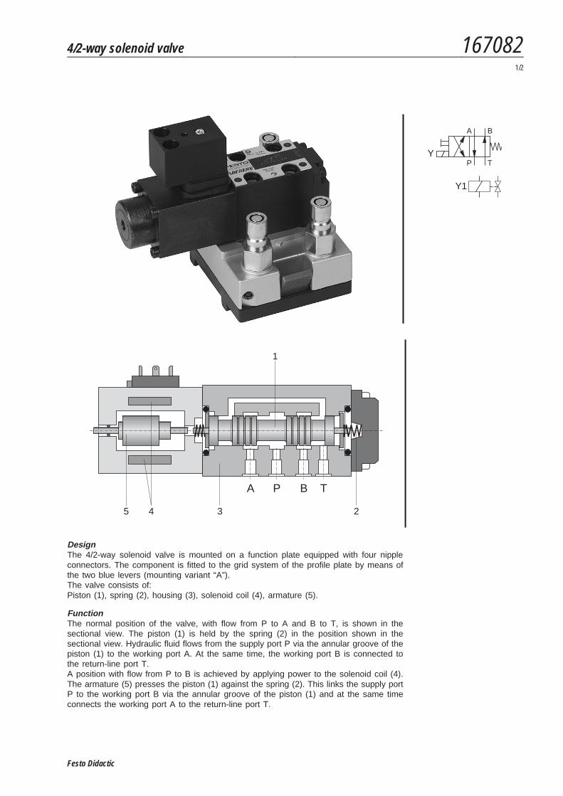
DesignThe 4/2-way solenoid valve is mounted on a function plate equipped with four nippleconnectors. The component is fitted to the grid system of the profile plate by means ofthe two blue levers (mounting variant “A”).The valve consists of:Piston (1), spring (2), housing (3), solenoid coil (4), armature (5).
FunctionThe normal position of the valve, with flow from P to A and B to T, is shown in thesectional view. The piston (1) is held by the spring (2) in the position shown in thesectional view. Hydraulic fluid flows from the supply port P via the annular groove of thepiston (1) to the working port A. At the same time, the working port B is connected tothe return-line port T.A position with flow from P to B is achieved by applying power to the solenoid coil (4).The armature (5) presses the piston (1) against the spring (2). This links the supply portP to the working port B via the annular groove of the piston (1) and at the same timeconnects the working port A to the return-line port T.
Y1
A
P
B
TY
1
A P B T
3 245
4/2-way solenoid valve 1670821/2
Festo Didactic
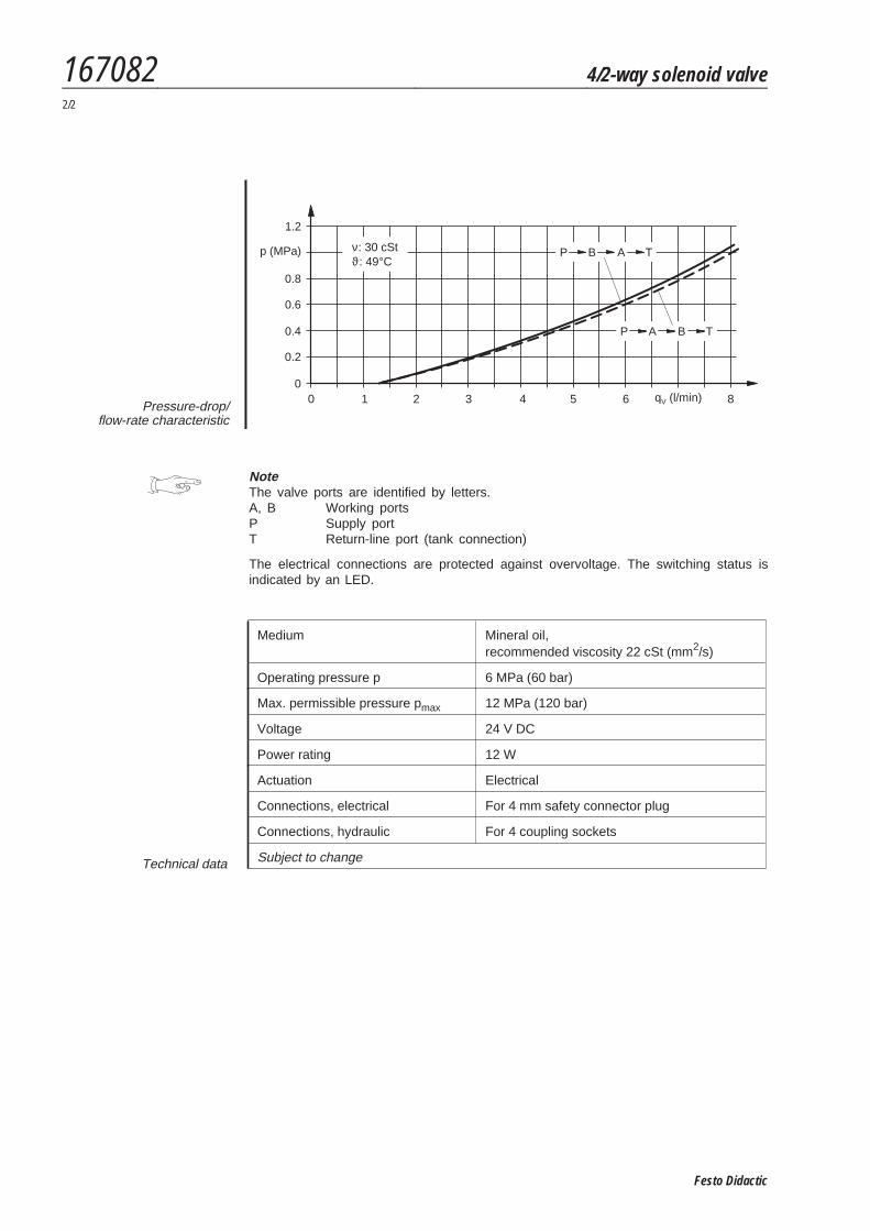
NoteThe valve ports are identified by letters.A, B Working portsP Supply portT Return-line port (tank connection)
The electrical connections are protected against overvoltage. The switching status isindicated by an LED.
Medium Mineral oil,recommended viscosity 22 cSt (mm2/s)
Operating pressure p 6 MPa (60 bar)
Max. permissible pressure pmax 12 MPa (120 bar)
Voltage 24 V DC
Power rating 12 W
Actuation Electrical
Connections, electrical For 4 mm safety connector plug
Connections, hydraulic For 4 coupling sockets
Subject to changeTechnical data
0 1 2 3 4 5 6 80
p (MPa)
0.2
0.4
0.6
0.8
1.2
νϑ: 30 cSt: 49°C
q (l/min)V
BP A T
AP B T
Pressure-drop/flow-rate characteristic
167082 4/2-way solenoid valve2/2
Festo Didactic
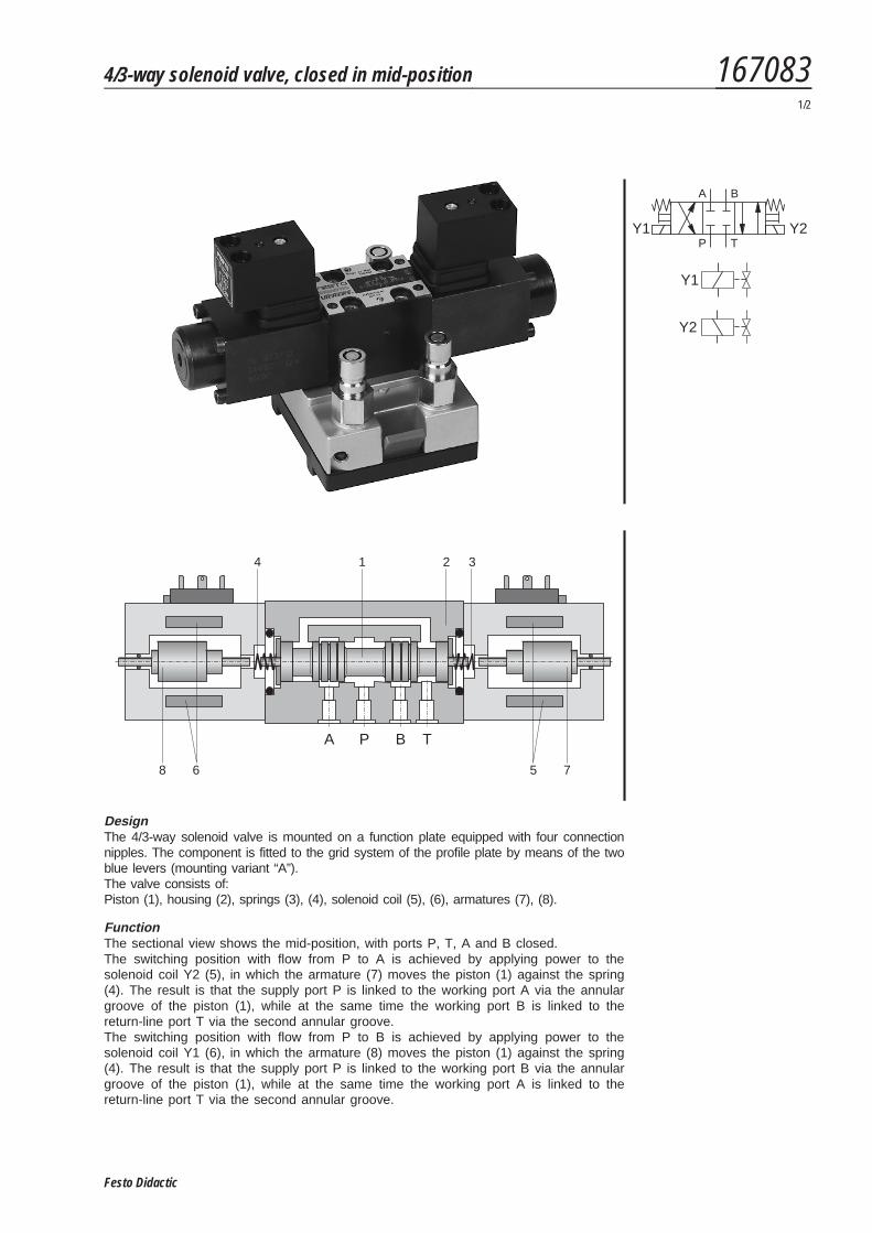
DesignThe 4/3-way solenoid valve is mounted on a function plate equipped with four connectionnipples. The component is fitted to the grid system of the profile plate by means of the twoblue levers (mounting variant “A”).The valve consists of:Piston (1), housing (2), springs (3), (4), solenoid coil (5), (6), armatures (7), (8).
FunctionThe sectional view shows the mid-position, with ports P, T, A and B closed.The switching position with flow from P to A is achieved by applying power to thesolenoid coil Y2 (5), in which the armature (7) moves the piston (1) against the spring(4). The result is that the supply port P is linked to the working port A via the annulargroove of the piston (1), while at the same time the working port B is linked to thereturn-line port T via the second annular groove.The switching position with flow from P to B is achieved by applying power to thesolenoid coil Y1 (6), in which the armature (8) moves the piston (1) against the spring(4). The result is that the supply port P is linked to the working port B via the annulargroove of the piston (1), while at the same time the working port A is linked to thereturn-line port T via the second annular groove.
Y1
Y2
A
P
B
TY1 Y2
5 7
1
A P B T
2 34
68
4/3-way solenoid valve, closed in mid-position 1670831/2
Festo Didactic
NoteThe valve ports are identified by letters.A, B Working portsP Supply portT Return-line port (tank connection)
The electrical connections are protected against overvoltage. The switching status isindicated by an LED.
Medium Mineral oil,recommended viscosity 22 cSt (mm2/s)
Operating pressure p 6 MPa (60 bar)
Max. permissible pressure pmax 12 MPa (120 bar)
Voltage 24 V DC
Power rating 12 W
Connections, electrical For 4 mm safety connector plug
Connections, hydraulic For 4 coupling sockets
Actuation Electrical
Subject to changeTechnical data
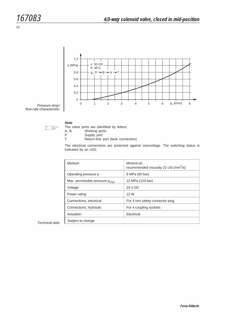
0 1 2 3 4 5 6 80
p (MPa)
0.2
0.4
0.6
0.8
1.2
q (l/min)V
BP A Tq :V
νϑ: 30 cSt: 46°C
Pressure-drop/flow-rate characteristic
167083 4/3-way solenoid valve, closed in mid-position2/2
Festo Didactic
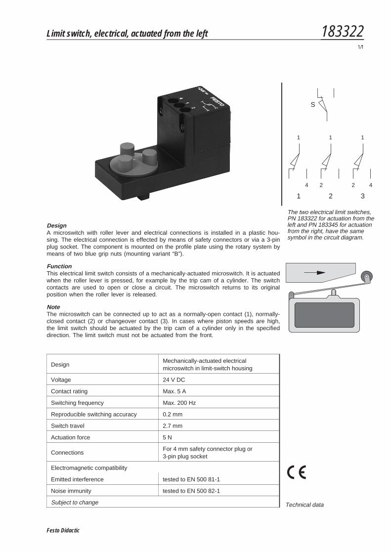
DesignA microswitch with roller lever and electrical connections is installed in a plastic hou-sing. The electrical connection is effected by means of safety connectors or via a 3-pinplug socket. The component is mounted on the profile plate using the rotary system bymeans of two blue grip nuts (mounting variant “B”).
FunctionThis electrical limit switch consists of a mechanically-actuated microswitch. It is actuatedwhen the roller lever is pressed, for example by the trip cam of a cylinder. The switchcontacts are used to open or close a circuit. The microswitch returns to its originalposition when the roller lever is released.
NoteThe microswitch can be connected up to act as a normally-open contact (1), normally-closed contact (2) or changeover contact (3). In cases where piston speeds are high,the limit switch should be actuated by the trip cam of a cylinder only in the specifieddirection. The limit switch must not be actuated from the front.
DesignMechanically-actuated electricalmicroswitch in limit-switch housing
Voltage 24 V DC
Contact rating Max. 5 A
Switching frequency Max. 200 Hz
Reproducible switching accuracy 0.2 mm
Switch travel 2.7 mm
Actuation force 5 N
ConnectionsFor 4 mm safety connector plug or3-pin plug socket
Electromagnetic compatibility
Emitted interference tested to EN 500 81-1
Noise immunity tested to EN 500 82-1
Subject to change Technical data
S
1 1 1
4 2 2 4
1 2 3
The two electrical limit switches,PN 183322 for actuation from theleft and PN 183345 for actuationfrom the right, have the samesymbol in the circuit diagram.
Limit switch, electrical, actuated from the left 1833221/1
Festo Didactic

Festo Didactic
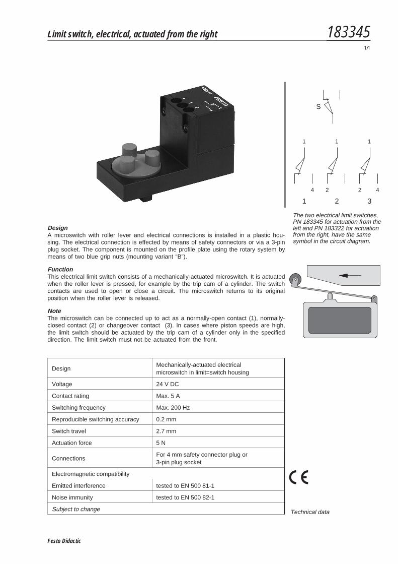
DesignA microswitch with roller lever and electrical connections is installed in a plastic hou-sing. The electrical connection is effected by means of safety connectors or via a 3-pinplug socket. The component is mounted on the profile plate using the rotary system bymeans of two blue grip nuts (mounting variant “B”).
FunctionThis electrical limit switch consists of a mechanically-actuated microswitch. It is actuatedwhen the roller lever is pressed, for example by the trip cam of a cylinder. The switchcontacts are used to open or close a circuit. The microswitch returns to its originalposition when the roller lever is released.
NoteThe microswitch can be connected up to act as a normally-open contact (1), normally-closed contact (2) or changeover contact (3). In cases where piston speeds are high,the limit switch should be actuated by the trip cam of a cylinder only in the specifieddirection. The limit switch must not be actuated from the front.
DesignMechanically-actuated electricalmicroswitch in limit=switch housing
Voltage 24 V DC
Contact rating Max. 5 A
Switching frequency Max. 200 Hz
Reproducible switching accuracy 0.2 mm
Switch travel 2.7 mm
Actuation force 5 N
ConnectionsFor 4 mm safety connector plug or3-pin plug socket
Electromagnetic compatibility
Emitted interference tested to EN 500 81-1
Noise immunity tested to EN 500 82-1
Subject to change Technical data
S
1 1 1
4 2 2 4
1 2 3
The two electrical limit switches,PN 183345 for actuation from theleft and PN 183322 for actuationfrom the right, have the samesymbol in the circuit diagram.
Limit switch, electrical, actuated from the right 1833451/1
Festo Didactic

Festo Didactic