Embed Size (px)
Citation preview
ww.sciencedirect.com
i n t e r n a t i o n a l j o u r n a l o f h y d r o g e n en e r g y 4 1 ( 2 0 1 6 ) 7 0 1 9e7 0 2 6
Available online at w
ScienceDirect
journal homepage: www.elsevier .com/locate/he
Electromagnetic design of a new axial and radialflux generator with the rotor back-irons
Erol Kurt a,*, Halil G€or b, Umut D€oner c
a Gazi University, Faculty of Technology, Department of Electrical and Electronics Engineering, 06500 Teknikokullar,
Ankara, Turkeyb Hakkari University, Faculty of Engineering, Department of Electrical and Electronics Engineering, 30000 Hakkari,
Turkeyc Gazi University, Institute of Science, Division of Electrical and Electronics Engineering, 06500 Teknikokullar,
Ankara, Turkey
a r t i c l e i n f o
Article history:
Received 15 November 2015
Received in revised form
7 February 2016
Accepted 8 February 2016
Available online 4 March 2016
Keywords:
Axial flux
Generator
Back-iron
Permanent magnet
Power
* Corresponding author.E-mail address: [email protected] (E.
http://dx.doi.org/10.1016/j.ijhydene.2016.02.00360-3199/Copyright © 2016, Hydrogen Ener
a b s t r a c t
The design and simulation of a new three-phase axial flux generator have been performed.
The generator is a permanent magnet machine (PMG) and consists of two rotors at two
sides and a stator at the middle. In the machine, each rotor has 16 rare earth disc-type
magnets and back-iron units and the stator at the middle has 24 coils. It has been un-
derstood that the generator produces directly sinusoidal output and requires no conversion
in the wave shape. The 3D simulations have been performed via the finite element analysis
(FEA) method by the magnetostatic and magnetodynamic tools. It has been found that the
machine generates 3.4 kW at 1000 rpm for the air gap of 1.5 mm. This gives the power
density of 336 kW/m3 for the rated value of the generator and it is higher than the power
densities of many axial flux generators in the literature. The maximal cogging torque value
has been estimated as 3.6 Nm, which is a good value for a back-iron machine. It has been
also proven that the waveform harmonics become lower at higher rotor speeds.
Copyright © 2016, Hydrogen Energy Publications, LLC. Published by Elsevier Ltd. All rights
reserved.
Introduction
The use of rare earth elements in the production of permanent
magnets (PMs) has accelerated the permanent generator
production. That has enhanced the importance of permanent
magnet synchronous machines (PMSM) in the wind energy
market. PM generators became popular in 1980's, after NdFeB
magnets were invented [1,2]. Since higher energy densities,
low cogging torque value, low cost and high mechanical
Kurt).34gy Publications, LLC. Publ
torque can be available with these machines, the PM genera-
tors have been used in many applications [3,4].
According to the literature [5], PM generators have some
superiorities over the asynchronous or current excited syn-
chronous generators. Efficiency, stability and reliability comes
in the first order to study on these generators [5]. They even
can produce direct sinusoidal current and that is counted
among the other advantages [6]. Strictly speaking, two distinct
PMG structures are found in the literature: Axial flux and
radial flux PMGs. If the flux goes through the coils in the radial
direction, that is a radial flux generator, however if the flux
ished by Elsevier Ltd. All rights reserved.
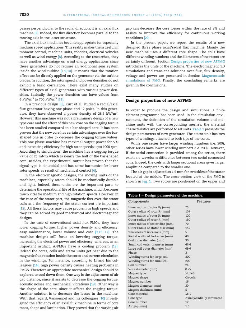
Table 1 e Design parameters of the machine.
Components Features
Inner radius of rotor R2 (mm) 75
Outer radius of rotor R2 (mm) 105
Inner radius of rotor R1 (mm) 120
Outer radius of rotor R1(mm) 150
Inner radius of stator disc (mm) 70
Outer radius of stator disc (mm) 155
Thickness of back-irons (mm) 5
Radial width of back-irons (mm) 40
Coil inner diameter (mm) 30
Small coil outer diameter (mm) 46.4
Large coil outer diameter (mm) 69.6
Phase 3
Winding turns for large coil 300
Winding turns for small coil 200
Coil number 24
Wire diameter (mm) 0.75
Magnet type NdFeB
Magnet shape Circular
Magnet number 16
Magnet diameter (mm) 30
Magnet thickness (mm) 5
Core material M19
Core type Axially/radially laminated
Core number 12
Air gap (mm) 1.5
i n t e rn a t i o n a l j o u r n a l o f h y d r o g e n en e r g y 4 1 ( 2 0 1 6 ) 7 0 1 9e7 0 2 67020
passes perpendicular to the radial direction, it is an axial flux
machine [7]. Indeed, the flux direction becomes parallel to the
moving axis in the latter structure.
The axial flux machines become appropriate for especially
medium speed applications. This realitymakes themuseful in
moment control, machine units, robotics, electrical vehicles
as well as wind energy [8]. According to the researches, they
have another advantage on wind energy applications since
these generators do not require an additional gear system
inside the wind turbine [1,9,10]. It means that the rotation
effect can be directly applied on the generator via the turbine
blades. In addition, the rotor speed and power densities do not
exhibit a basic correlation. There exist many studies on
different types of axial generators with various power den-
sities. Basically the power densities can have values from
6 kW/m3 to 700 kW/m3 [11].
In a previous design [6], Kurt et al. studied a radial/axial
flux generator having one phase and 12 poles. In this gener-
ator, they have observed a power density of 28.5 kW/m3.
However this machine was not a preliminary design of a new
type core and the effect of this new core on the cogging torque
has been studied compared to a bar-shaped core. It has been
proven that the new core has certain advantages over the bar-
shaped one in order to decrease the cogging torque values.
This one phase machine has maximal output power for 5 U
and increasing efficiency for high rotor speeds upto 1000 rpm.
According to simulations, the machine has a cogging torque
value of 25 mNm which is nearly the half of the bar-shaped
core. Besides, the experimental output has proven that the
signal type is sinusoidal and has some harmonics for lower
rotor speeds as result of mechanical contact [6].
In the electromagnetic designs, the moving units of the
machines, especially rotors should be mechanically durable
and light. Indeed, these units are the important parts to
determine the operational life of themachine, which becomes
much vital for medium and high rotation speeds. However, in
the case of the stator part, the magnetic flux over the stator
coils and the frequency of the stator current are important
[12]. All these factors may cause problem in high speeds and
they can be solved by good mechanical and electromagnetic
designs.
In the case of conventional axial flux PMGs, they have
lower cogging torque, higher power density and efficiency,
easy maintenance, lower volume and cost [9,13e17]. The
machine designs still focus on lowering cogging torque,
increasing the electrical power and efficiency, whereas, as an
important artifact, AFPMGs have a cooling problem [18].
Indeed the cores, coils and stator units get heat due to the
magnetic flux rotation inside the cores and current circulation
in the windings. For instance, according to Li and his col-
leagues [14], high power density causes heating problems in
PMGS. Therefore an appropriate mechanical design should be
explored to cool down them. One way is the adjustment of air
gap distance, since it assists to decrease the cogging torque,
acoustic noises and mechanical vibrations [19]. Other way is
the shape of the core, since it affects the cogging torque.
Another solution is to decrease the losses in the machine.
With that regard, Vansompel and his colleagues [10] investi-
gated the efficiency of an axial flux machine in terms of core
mass, shape and lamination. They proved that the varying air
gap can decrease the core losses within the rate of 8% and
assists to improve the efficiency for continuous working
conditions [20].
In the present paper, we report the results of a new
designed three phase axial/radial flux machine. Mainly the
new machine uses a different core shape. The coils have
different winding numbers and the diameters of the rotors are
certainly different. Section Design properties of new AFPMG
introduces the units of the machine. The electromagnetic 3D
simulations and transient solutions over flux, flux density,
voltage and power are presented in Section Magnetostatic
simulations of PMG. Finally, the concluding remarks are
given in the conclusions.
Design properties of new AFPMG
In order to produce the design and simulations, a finite
element programme has been used. In the simulation envi-
ronment, the definition of the simulation volume and ma-
chine units with the corresponding meshes, the material
characteristics are performed to all units. Table 1 presents the
design parameters of new generator. The stator unit has two
types of windings attached to both tips of the cores.
While one series have larger winding numbers (i.e. 300),
other series have lower winding numbers (i.e. 200). However,
if the serial connection is provided among the series, there
exists no waveform difference between two serial connected
coils. Indeed, the coils with larger sectional areas gives larger
amplitude compared to the smaller one.
The air gap is adjusted as 1.5 mm for two sides of the stator
located at the middle. The cross-section view of the PMG is
shown in Fig. 1. Two rotors are positioned on the upper and
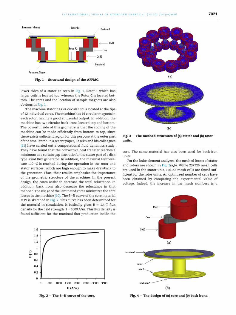
Fig. 1 e Structural design of the AFPMG.
Fig. 3 e The meshed structures of (a) stator and (b) rotor
units.
i n t e r n a t i o n a l j o u r n a l o f h y d r o g e n en e r g y 4 1 ( 2 0 1 6 ) 7 0 1 9e7 0 2 6 7021
lower sides of a stator as seen in Fig. 1. Rotor-1 which has
larger coils is located top, whereas the Rotor-2 is located bot-
tom. The cores and the location of sample magnets are also
obvious in Fig. 1.
The machine stator has 24 circular coils located at the tips
of 12 individual cores. Themachine has 16 circularmagnets in
each rotor, having a good sinusoidal output. In addition, the
machine has two circular back-irons located top and bottom.
The powerful side of this geometry is that the cooling of the
machine can be made efficiently from bottom to top, since
there exists sufficient region for this purpose at the outer part
of the small rotor. In a recent paper, Rasekh and his colleagues
[21] have carried out a computational fluid dynamics study.
They have found that the convective heat transfer reaches a
minimumat a certain gap size ratio for the stator part of a disk
type axial flux generator. In addition, the maximal tempera-
ture 110 �C is reached during the operation in the rotor and
stator surfaces, which are high enough to make drawback to
the generator. Thus, their results emphasize the importance
of the geometric structure of the machine. In the present
design, the cores assist to decrease the total reluctance. In
addition, back irons also decrease the reluctance in that
manner. The usage of the laminated cores minimizes the core
losses in the machine [10]. The BeH curve of the core material
M19 is sketched in Fig. 2. This curve has been determined for
the material in simulation. It basically gives B ¼ 1.4 T flux
density for the field strengthH¼ 1000 A/m. This flux density is
found sufficient for the maximal flux production inside the
Fig. 2 e The BeH curve of the core.
core. The same material has also been used for back-iron
units.
For the finite element analyzes, themeshed forms of stator
and rotors are shown in Fig. 3(a,b). While 237326 mesh cells
are used in the stator unit, 156148 mesh cells are found suf-
ficient for the rotor units. An optimized number of cells have
been obtained by comparing the experimental value of
voltage. Indeed, the increase in the mesh numbers is a
Fig. 4 e The design of (a) core and (b) back irons.
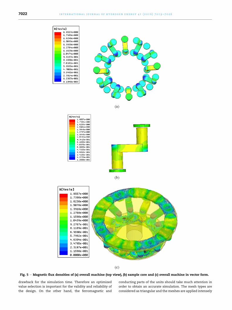
Fig. 5 e Magnetic flux densities of (a) overall machine (top view), (b) sample core and (c) overall machine in vector form.
i n t e rn a t i o n a l j o u r n a l o f h y d r o g e n en e r g y 4 1 ( 2 0 1 6 ) 7 0 1 9e7 0 2 67022
drawback for the simulation time. Therefore an optimized
value selection is important for the validity and reliability of
the design. On the other hand, the ferromagnetic and
conducting parts of the units should take much attention in
order to obtain an accurate simulation. The mesh types are
considered as triangular and themeshes are applied intensely
i n t e r n a t i o n a l j o u r n a l o f h y d r o g e n en e r g y 4 1 ( 2 0 1 6 ) 7 0 1 9e7 0 2 6 7023
for magnetic units such as core, back-iron, magnets and coil.
The meshes have also been enhanced for edges and tips in
order to achieve better simulation results. For the electrical
connection of the windings in Fig. 3(a), the windings at the top
and bottom tips of each core have been connected in series.
For the overall phase connections we refer to Refs. [22e24].
A sample core consisting of 40 laminated layers with
0.5 mm thickness is shown in Fig. 4(a). In order to obtain a
circular form, each layer has its specific width. The machine
has 12 cores in total. It has been proven in our previous study
that this core geometry enhances the cogging torque value of
the machine [6,22]. At the tips of the cores, the coils are
located.
The adjacent core tips and concentrated coils (with the
distribution factor 1) are situated on the stator with an elec-
trical angle of 22.5�. In the rotor unit shown in Fig. 4(b), the
magnet housings are indicated on the yellow filling material.
There exist 16 circular pair poles in the machine. Note that
there exist also housings at the top rotor for the same magnet
sizes. The magnets are adjusted as 30 mm in diameter and
5 mm in thickness in the design. In order to sustain maximal
flux, the back-irons contacts the magnets at both sides.
220
320 VAVBVC
Magnetostatic simulations of PMG
Magnetostatic simulations are important to identify the flux
density for different orientations of the rotors and stator.
Because of the core geometry and the structures of rotor and
stator, the flux topology differs from the earlier machines. In
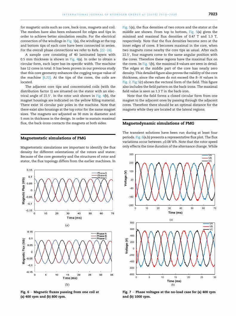
Fig. 6 e Magnetic fluxes passing from one coil at
(a) 400 rpm and (b) 800 rpm.
Fig. 5(a), the flux densities of two rotors and the stator at the
middle are shown. From top to bottom, Fig. 5(a) gives the
minimal and maximal flux densities of 0.47 T and 1.3 T,
respectively. Note that the flux densities become zero at the
inner edges of cores. B becomes maximal in the core, when
two magnets come nearby the core tips as usual. After each
22.5�, four magnets come to the same angular position with
the cores. Therefore these regions have the maximal flux on
the cores. In Fig. 5(b), the maximal B values are seen in detail.
The edges at the middle part of the core has nearly zero
density. This detailed figure also proves the validity of the core
thickness, since the values do not exceed the BeH values in
Fig. 2. Fig 5(c) shows the vectoral form of the field. This figure
also includes the field pattern on the back-irons. Themaximal
field value is seen as 1.3 T in the back-iron.
Note that the field forms a closed circular form from one
magnet to the adjacent ones by passing through the adjacent
cores. Therefore there should be an optimal distance for the
magnets while they are located at the lateral regions.
Magnetodynamic simulations of PMG
The transient solutions have been run during at least four
periods. Fig. 6(a,b) presents a representative flux plot. The flux
variations occur between ±0.08 Wb. Note that the rotor speed
only effects the time duration of the alternance change.While
(a)
(b)
-280
-180
-80
20
120
0 10 20 30 40 50 60 70
Volta
ge (V
)
Time (ms)
-800
-600
-400
-200
0
200
400
600
800
0 5 10 15 20 25 30
VAVBVC
Volta
ge (V
)
Time (ms)
Fig. 7 e Phase voltages at the no-load case for (a) 400 rpm
and (b) 1000 rpm.
(a)
(b)
-300
-200
-100
0
100
200
300
0 5 10 15 20 25 30 35 40 45 50
VAVBVC
Volta
ge (V
)
Time (ms)
-400
-300
-200
-100
0
100
200
300
400
0 5 10 15 20 25 30
VAVBVC
Volta
ge (V
)
Time (ms)
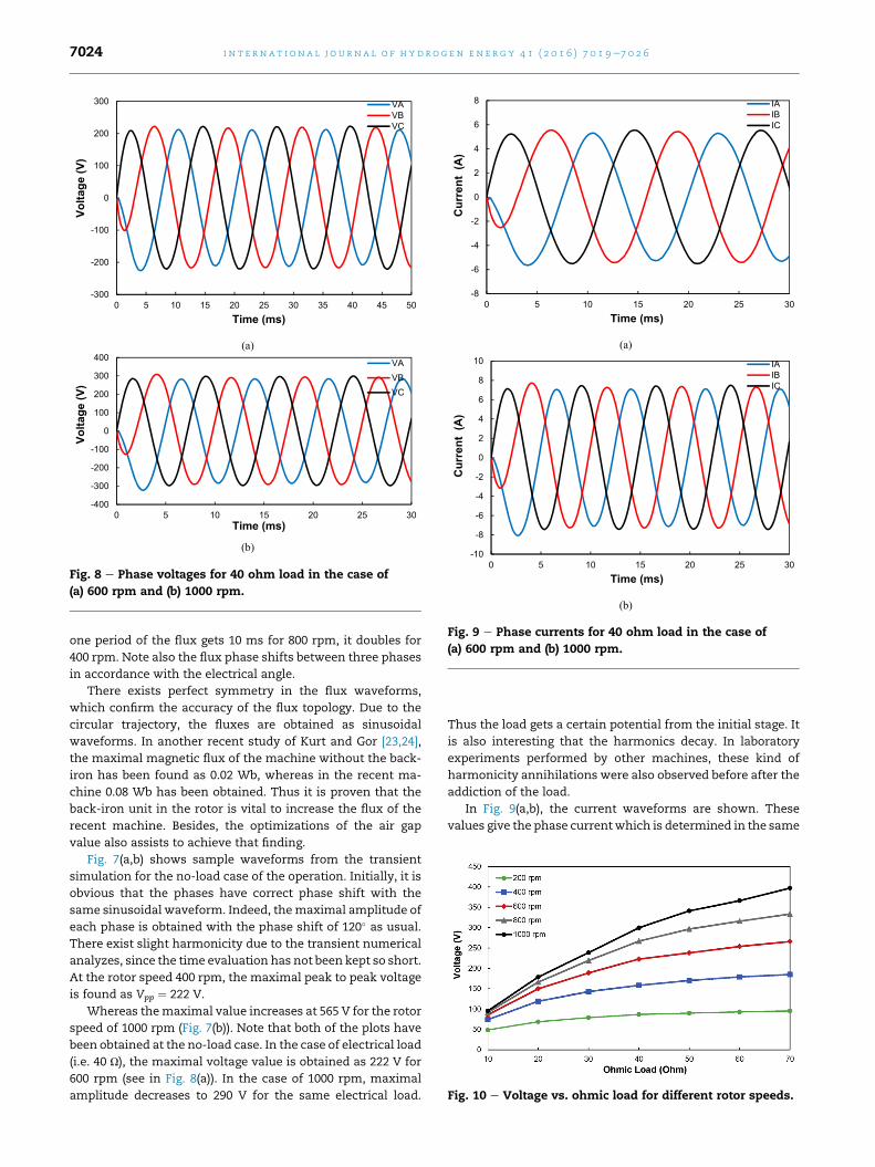
Fig. 8 e Phase voltages for 40 ohm load in the case of
(a) 600 rpm and (b) 1000 rpm.
(a)
(b)
-8
-6
-4
-2
0
2
4
6
8
0 5 10 15 20 25 30
IAIBIC
Cur
rent
(A
)
Time (ms)
-10
-8
-6
-4
-2
0
2
4
6
8
10
0 5 10 15 20 25 30
IAIBIC
Cur
rent
(A
)
Time (ms)
Fig. 9 e Phase currents for 40 ohm load in the case of
(a) 600 rpm and (b) 1000 rpm.
Fig. 10 e Voltage vs. ohmic load for different rotor speeds.
i n t e rn a t i o n a l j o u r n a l o f h y d r o g e n en e r g y 4 1 ( 2 0 1 6 ) 7 0 1 9e7 0 2 67024
one period of the flux gets 10 ms for 800 rpm, it doubles for
400 rpm. Note also the flux phase shifts between three phases
in accordance with the electrical angle.
There exists perfect symmetry in the flux waveforms,
which confirm the accuracy of the flux topology. Due to the
circular trajectory, the fluxes are obtained as sinusoidal
waveforms. In another recent study of Kurt and Gor [23,24],
the maximal magnetic flux of the machine without the back-
iron has been found as 0.02 Wb, whereas in the recent ma-
chine 0.08 Wb has been obtained. Thus it is proven that the
back-iron unit in the rotor is vital to increase the flux of the
recent machine. Besides, the optimizations of the air gap
value also assists to achieve that finding.
Fig. 7(a,b) shows sample waveforms from the transient
simulation for the no-load case of the operation. Initially, it is
obvious that the phases have correct phase shift with the
same sinusoidal waveform. Indeed, themaximal amplitude of
each phase is obtained with the phase shift of 120� as usual.
There exist slight harmonicity due to the transient numerical
analyzes, since the time evaluation has not been kept so short.
At the rotor speed 400 rpm, the maximal peak to peak voltage
is found as Vpp ¼ 222 V.
Whereas themaximal value increases at 565 V for the rotor
speed of 1000 rpm (Fig. 7(b)). Note that both of the plots have
been obtained at the no-load case. In the case of electrical load
(i.e. 40 U), the maximal voltage value is obtained as 222 V for
600 rpm (see in Fig. 8(a)). In the case of 1000 rpm, maximal
amplitude decreases to 290 V for the same electrical load.
Thus the load gets a certain potential from the initial stage. It
is also interesting that the harmonics decay. In laboratory
experiments performed by other machines, these kind of
harmonicity annihilations were also observed before after the
addiction of the load.
In Fig. 9(a,b), the current waveforms are shown. These
values give the phase currentwhich is determined in the same
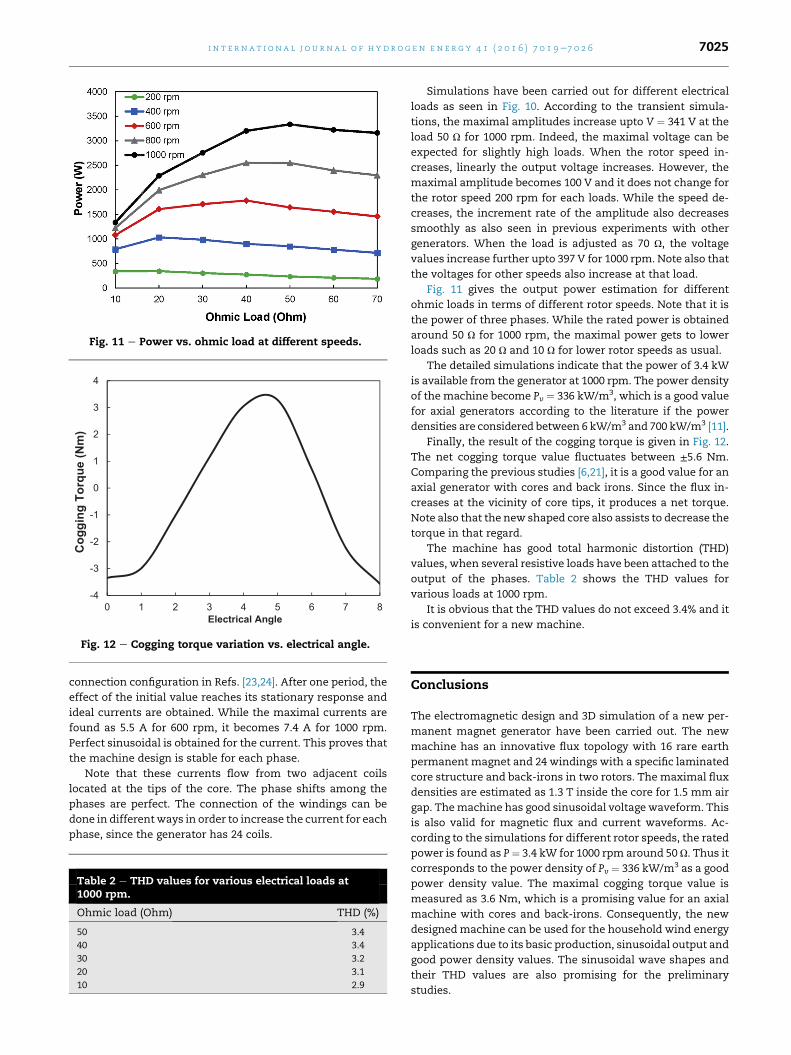
Fig. 11 e Power vs. ohmic load at different speeds.
-4
-3
-2
-1
0
1
2
3
4
0 1 2 3 4 5 6 7 8
Cog
ging
Tor
que
(Nm
)
Electrical Angle
Fig. 12 e Cogging torque variation vs. electrical angle.
i n t e r n a t i o n a l j o u r n a l o f h y d r o g e n en e r g y 4 1 ( 2 0 1 6 ) 7 0 1 9e7 0 2 6 7025
connection configuration in Refs. [23,24]. After one period, the
effect of the initial value reaches its stationary response and
ideal currents are obtained. While the maximal currents are
found as 5.5 A for 600 rpm, it becomes 7.4 A for 1000 rpm.
Perfect sinusoidal is obtained for the current. This proves that
the machine design is stable for each phase.
Note that these currents flow from two adjacent coils
located at the tips of the core. The phase shifts among the
phases are perfect. The connection of the windings can be
done in differentways in order to increase the current for each
phase, since the generator has 24 coils.
Table 2 e THD values for various electrical loads at1000 rpm.
Ohmic load (Ohm) THD (%)
50 3.4
40 3.4
30 3.2
20 3.1
10 2.9
Simulations have been carried out for different electrical
loads as seen in Fig. 10. According to the transient simula-
tions, the maximal amplitudes increase upto V ¼ 341 V at the
load 50 U for 1000 rpm. Indeed, the maximal voltage can be
expected for slightly high loads. When the rotor speed in-
creases, linearly the output voltage increases. However, the
maximal amplitude becomes 100 V and it does not change for
the rotor speed 200 rpm for each loads. While the speed de-
creases, the increment rate of the amplitude also decreases
smoothly as also seen in previous experiments with other
generators. When the load is adjusted as 70 U, the voltage
values increase further upto 397 V for 1000 rpm. Note also that
the voltages for other speeds also increase at that load.
Fig. 11 gives the output power estimation for different
ohmic loads in terms of different rotor speeds. Note that it is
the power of three phases. While the rated power is obtained
around 50 U for 1000 rpm, the maximal power gets to lower
loads such as 20 U and 10 U for lower rotor speeds as usual.
The detailed simulations indicate that the power of 3.4 kW
is available from the generator at 1000 rpm. The power density
of the machine become Pv ¼ 336 kW/m3, which is a good value
for axial generators according to the literature if the power
densities are considered between 6 kW/m3 and 700 kW/m3 [11].
Finally, the result of the cogging torque is given in Fig. 12.
The net cogging torque value fluctuates between ±5.6 Nm.
Comparing the previous studies [6,21], it is a good value for an
axial generator with cores and back irons. Since the flux in-
creases at the vicinity of core tips, it produces a net torque.
Note also that the new shaped core also assists to decrease the
torque in that regard.
The machine has good total harmonic distortion (THD)
values, when several resistive loads have been attached to the
output of the phases. Table 2 shows the THD values for
various loads at 1000 rpm.
It is obvious that the THD values do not exceed 3.4% and it
is convenient for a new machine.
Conclusions
The electromagnetic design and 3D simulation of a new per-
manent magnet generator have been carried out. The new
machine has an innovative flux topology with 16 rare earth
permanent magnet and 24 windings with a specific laminated
core structure and back-irons in two rotors. The maximal flux
densities are estimated as 1.3 T inside the core for 1.5 mm air
gap. Themachine has good sinusoidal voltage waveform. This
is also valid for magnetic flux and current waveforms. Ac-
cording to the simulations for different rotor speeds, the rated
power is found as P¼ 3.4 kW for 1000 rpm around 50 U. Thus it
corresponds to the power density of Pv ¼ 336 kW/m3 as a good
power density value. The maximal cogging torque value is
measured as 3.6 Nm, which is a promising value for an axial
machine with cores and back-irons. Consequently, the new
designedmachine can be used for the household wind energy
applications due to its basic production, sinusoidal output and
good power density values. The sinusoidal wave shapes and
their THD values are also promising for the preliminary
studies.
i n t e rn a t i o n a l j o u r n a l o f h y d r o g e n en e r g y 4 1 ( 2 0 1 6 ) 7 0 1 9e7 0 2 67026
Acknowledgements
The authors are grateful to Gazi University, Scientific Re-
searches Project Unit for the support of this project under the
Grant No: 07/2011-25 and EU Ministry of Turkey National
Agency Grant No: 2015-1-TR01-KA203-021342 (Innovative Eu-
ropean Studies on Renewable Energy Systems ) for the
compilation of the research. Thismachine has been suggested
to TPE as a new patent under No. 2014/16384.
r e f e r e n c e s
[1] Kurt E, Aslan S, Demirtas M, Guven ME. Design and analysisof an axial-field permanent magnet generator with multiplestators and rotors. In: Proceedings of the 2011 3th. IEEE Conf.power Engineering, energy and electrical Drives,Torremolinos (Malaga), Spain; 2011. p. 2e4.
[2] Yıldırız E, Aydemir MT. Analysis, design and implementationof an axial flux, permanent magnet machine to be used in alow power wind generator. J Fac Eng Archit Gazi Univ2009;24(3):525e31.
[3] Singh BP, Dwivedi S. A state of art on different configurationsof permanent magnet brushless machines. IE (I) J-EL2006;78:63e73.
[4] Barave SP, Chowdhury BH. Optimal design of inductiongenerators for space applications. IEEE Trans Aerosp ElectronSys 2009;45(3):1126e37.
[5] Guannan D, Haifeng W, Hui G, Guobiao G. Direct drivepermanent magnet wind generator design andelectromagnetic field finite element analysis. IEEE Tran ApplSupercond 2010;20(3):1883e7.
[6] Kurt E, G€or H, Demirtas‚ M. Theoretical and experimentalanalyses of a single phase permanent magnet generator(PMG) with multiple cores having axial and radial directedfluxes. Energy Convers Manag 2014;7:163e72.
[7] Wallace RR, Lipo TA, Moran LA, Tapiai JA. Design andconstruction of a permanent magnet axial flux synchronousgenerator. Milwaukee: Electric Machines and DrivesConference IEEE; 1997. MA1/4.1eMA1/4.3.
[8] Bumby JR, Martin R. Axial-flux permanent-magnet air-coredgenerator for small-scale wind turbines. Proc IEE- ElectrPower Appl 2006;152(5):63e73.
[9] Qamaruzzaman A, Pradikta P, Dahono A. Analyticalprediction of inductances of slotless axial-flux permanentmagnet synchronous generator using Quasi-3D method. Int JElectr Eng Inf 2009;1(2):115e25.
[10] Vansompel H, Sergeant P, Dupre L. Optimized designconsidering the mass influence of an axial flux
permanent-magnet synchronous generator withconcentrated pole windings. Magn IEEE Trans2010;46(12):4101e7.
[11] Gholomian SA, Yousefi A. Power density comparison forthree phase non-slotted double-sided AFPM motors. Aust JBasic Sci 2010;4(12):5497e955.
[12] Sadeghierad M, Lesani H, Monsef H, Darabi A. Designconsiderations of high speed axial flux permanent magnetgenerator with coreless stator. Singapore: Power EngineeringConference, IPEC 2007; 2007. p. 1097e102.
[13] Muljadi E, Butterfield CP, Wan UH. Axial-flux modularpermanent-magnet generator with a toroidal winding forwind-turbine applications. IEEE Trans Ind Appl1999;35(4):831e6.
[14] Li J, Choi DW, Cho YH. Development of a natural cooled axialflux permanent magnet generator for wind turbine.Hangzhou: Industrial Electronics (ISIE), 2012 IEEEInternational Symposium; 2012. p. 635e40.
[15] Javadi S, Mirsalim M. A coreless axial-flux permanent-magnet generator for automotive applications. IEEE TransMagn 2008;44(12):4591e8.
[16] Dosiek L, Pillay P. Cogging torque reduction in permanentmagnet machines. Ind Appl IEEE Trans2007;43(6):1565e71.
[17] Chan TF, Weimin W, Lai LL. Magnetic field in atransverse- and axial-flux permanent magnetsynchronous generator from 3-D FEA. Magn IEEE Trans2012;48(2):1055e8.
[18] Bumby JR, Martin R. Axial flux permanent magnet generatorfor engine integration. In: Published at the 12. Int. StirlingEngine Conf., Durham; 2005.
[19] Chan CC. Axial-field electrical machines-design andapplications. IEEE Trans Energy Conv 1987;2(2):294e300.
[20] Vansompel H, Sergeant P, Dupre L, Van den Bossche A. Axial-flux PM machines with variable air gap. Ind Electron IEEETrans 2014;61(2):730e7.
[21] Rasekh Alireza, Sergeant Peter, Vierendeels Jan. Convectiveheat transfer prediction in disk-type electrical machines.Appl Therm Eng 2015;91:778e90.
[22] Kurt E, Aslan S, G€or H, Demirtas‚ M. Electromagnetic analysesof two axial-flux permanent magnet generators (PMGs).Istanbul, Turkey: Power Engineering, Energy and ElectricalDrives (POWERENG), 2013 Fourth International ConferenceIEEE; 2013. p. 290e4.
[23] Gor H, Kurt E. Waveform characteristics and losses of a newdouble sided axial and radial flux generator. Int J HydrogenEnergy 2016. http://dx.doi.org/10.1016/j.ijhydene.2015.12.172.
[24] Gor H, Kurt E. Preliminary studies of a new permanentmagnet generator (PMG) with the axial and radial fluxmorphology. Int J Hydrogen Energy 2016;41(17):7005e18.