Embed Size (px)
Citation preview

Report No: EF/2006/10012 FCC ID: POOWML-C46 Issue Date: Apr. 24, 2006
Page: 1 of 53
The results shown in this test report refer only to the sample(s) tested unless otherwise stated. This test report cannot be reproduced, except in full, without prior written permission of the Company.
SGS Taiwan Ltd. No. 134, Wu Kung Rd., Wuku Industrial Zone, Taipei Country, Taiwan. / 台北縣五股工業區五工路134號 台灣檢驗科技股份有限公司 t (886-2) 2299-3939 f (886-2) 2298-2698 www.sgs.com.tw
ELECTROMAGNETIC EMISSIONS COMPLIANCE REPORT
INTENTIONAL RADIATOR CERTIFICATION TO FCC PART 15 SUBPART C REQUIREMENT
FULL MODULAR APPROVAL OF
Product Name: Bluetooth Module
Brand Name: Mitsumi
Model Name: WML-C46NBR,WML-C46NHR, WML-C46ABR,WML-C46AHR
Model Difference: N: external antenna , A: internal antenna B:BCSP; H:UART
FCC ID: POOWML-C46
Report No.: EF/2006/10012
Issue Date: Apr. 24, 2006
FCC Rule Part: §15.247
Prepared for: MITSUMI ELECTRIC CO., LTD. 2-11-2,Tsurumaki,Tama-shi,Tokyo Japan
Prepared by: SGS Taiwan Ltd.
No. 134, Wu Kung Rd., Wuku Industrial Zone, Taipei County, Taiwan.
Note: This report shall not be reproduced except in full, without the written ap-proval of SGS Taiwan Ltd. This document may be altered or revised by SGS Tai-wan Ltd. personnel only, and shall be noted in the revision section of the document.

Report No: EF/2006/10012 FCC ID: POOWML-C46 Issue Date: Apr. 24, 2006
The results shown in this test report refer only to the sample(s) tested unless otherwise stated. This test report cannot be reproduced, except in full, without prior written permission of the Company.
SGS Taiwan Ltd. No. 134, Wu Kung Rd., Wuku Industrial Zone, Taipei Country, Taiwan. / 台北縣五股工業區五工路134號 台灣檢驗科技股份有限公司 t (886-2) 2299-3939 f (886-2) 2298-2698 www.sgs.com.tw
VERIFICATION OF COMPLIANCE
Applicant: MITSUMI ELECTRIC CO., LTD. 2-11-2,Tsurumaki,Tama-shi,Tokyo Japan
Equipment Under Test: Bluetooth Module
Brand Name: Mitsumi
FCC ID Number: POOWML-C46
Model No.: WML-C46NBR,WML-C46NHR, WML-C46ABR, WML- C46AHR
Model Difference: N: external antenna , A: internal antenna B:BCSP; H:UART
File Number: EF/2006/10012
Date of test: Apr. 17, 2006 ~ Apr. 21, 2006
Date of EUT Received: Apr. 16, 2006
We hereby certify that: The above equipment was tested by SGS Taiwan Ltd. The test data, data evaluation, test proce-dures, and equipment configurations shown in this report were made in accordance with the procedures given in ANSI C63.4 (2003) and the energy emitted by the sample EUT tested as described in this report is in compliance with conducted and radiated emission limits of FCC Rules Part 15.247 The test results of this report relate only to the tested sample identified in this report.
Test By:
Date Apr. 24, 2006
Danny Yeh
Prepared By:
Date Apr. 24, 2006
Cathy Kuo
Approved By:
Date Apr. 24, 2006
Vincent Su
Report No: EF/2006/10012 FCC ID: POOWML-C46 Issue Date: Apr. 24, 2006
The results shown in this test report refer only to the sample(s) tested unless otherwise stated. This test report cannot be reproduced, except in full, without prior written permission of the Company.
SGS Taiwan Ltd. No. 134, Wu Kung Rd., Wuku Industrial Zone, Taipei Country, Taiwan. / 台北縣五股工業區五工路134號 台灣檢驗科技股份有限公司 t (886-2) 2299-3939 f (886-2) 2298-2698 www.sgs.com.tw
Version
Version No. Date
00 Apr.24, 2006

Report No: EF/2006/10012 FCC ID: POOWML-C46 Issue Date: Apr. 24, 2006
The results shown in this test report refer only to the sample(s) tested unless otherwise stated. This test report cannot be reproduced, except in full, without prior written permission of the Company.
SGS Taiwan Ltd. No. 134, Wu Kung Rd., Wuku Industrial Zone, Taipei Country, Taiwan. / 台北縣五股工業區五工路134號 台灣檢驗科技股份有限公司 t (886-2) 2299-3939 f (886-2) 2298-2698 www.sgs.com.tw
Table of Contents
1. GENERAL INFORMATION.........................................................................................................7 1.1. Product Description ............................................................................................................................7 1.2. Related Submittal(s) / Grant (s) ..........................................................................................................7 1.3. Test Methodology ...............................................................................................................................7 1.4. Test Facility.........................................................................................................................................7 1.5. Special Accessories .............................................................................................................................7 1.6. Equipment Modifications....................................................................................................................7
2. SYSTEM TEST CONFIGURATION............................................................................................8 2.1. EUT Configuration .............................................................................................................................8 2.2. EUT Exercise ......................................................................................................................................8 2.3. Test Procedure.....................................................................................................................................8 2.4. Configuration of Tested System..........................................................................................................9
3. SUMMARY OF TEST RESULTS ...............................................................................................10 4. DESCRIPTION OF TEST MODES ............................................................................................10 5. CONDUCTED EMISSION TEST................................................................................................11
5.1. Standard Applicable ..........................................................................................................................11 5.2. EUT Setup.........................................................................................................................................11 5.3. Measurement Procedure....................................................................................................................11 5.4. Measurement Equipment Used: ........................................................................................................12 5.5. Measurement Result..........................................................................................................................12
6. PEAK OUTPUT POWER MEASUREMENT............................................................................13 6.1. Standard Applicable ..........................................................................................................................13 6.2. Measurement Procedure....................................................................................................................13 6.3. Measurement Result..........................................................................................................................13 6.4. Measurement Equipment Used: ........................................................................................................13
7. 20dB BAND WIDTH .....................................................................................................................16 7.1. Standard Applicable ..........................................................................................................................16 7.2. Measurement Procedure....................................................................................................................16 7.3. Measurement Result..........................................................................................................................16 7.4. Measurement Equipment Used: ........................................................................................................16
Report No: EF/2006/10012 FCC ID: POOWML-C46 Issue Date: Apr. 24, 2006
The results shown in this test report refer only to the sample(s) tested unless otherwise stated. This test report cannot be reproduced, except in full, without prior written permission of the Company.
SGS Taiwan Ltd. No. 134, Wu Kung Rd., Wuku Industrial Zone, Taipei Country, Taiwan. / 台北縣五股工業區五工路134號 台灣檢驗科技股份有限公司 t (886-2) 2299-3939 f (886-2) 2298-2698 www.sgs.com.tw
8. 100KHz BANDWIDTH OF BAND EDGES MEASUREMENT...............................................19
8.1. Standard Applicable ..........................................................................................................................19 8.2. Measurement Procedure....................................................................................................................19 8.3. Measurement Result..........................................................................................................................19 8.4. Measurement Equipment Used: ........................................................................................................19
9. SPURIOUS RADIATED EMISSION TEST...............................................................................23 9.1. Standard Applicable ..........................................................................................................................23 9.2. EUT Setup.........................................................................................................................................23 9.3. Measurement Procedure....................................................................................................................23 9.4. Test SET-UP (Block Diagram of Configuration) ..............................................................................24 9.5. Measurement Equipment Used: ........................................................................................................25 9.6. Field Strength Calculation ................................................................................................................25 9.7. Measurement Result..........................................................................................................................25
10. FREQUENCY SEPARATION.....................................................................................................38 10.1. Standard Applicable ..........................................................................................................................38 10.2. Measurement Procedure....................................................................................................................38 10.3. Measurement Result..........................................................................................................................38 10.4. Measurement Equipment Used: ........................................................................................................38
11. NUMBER OF HOPPING FREQUENCY ...................................................................................40 11.1. Standard Applicable ..........................................................................................................................40 11.2. Measurement Procedure....................................................................................................................40 11.3. Measurement Result..........................................................................................................................40 11.4. Measurement Equipment Used: ........................................................................................................41
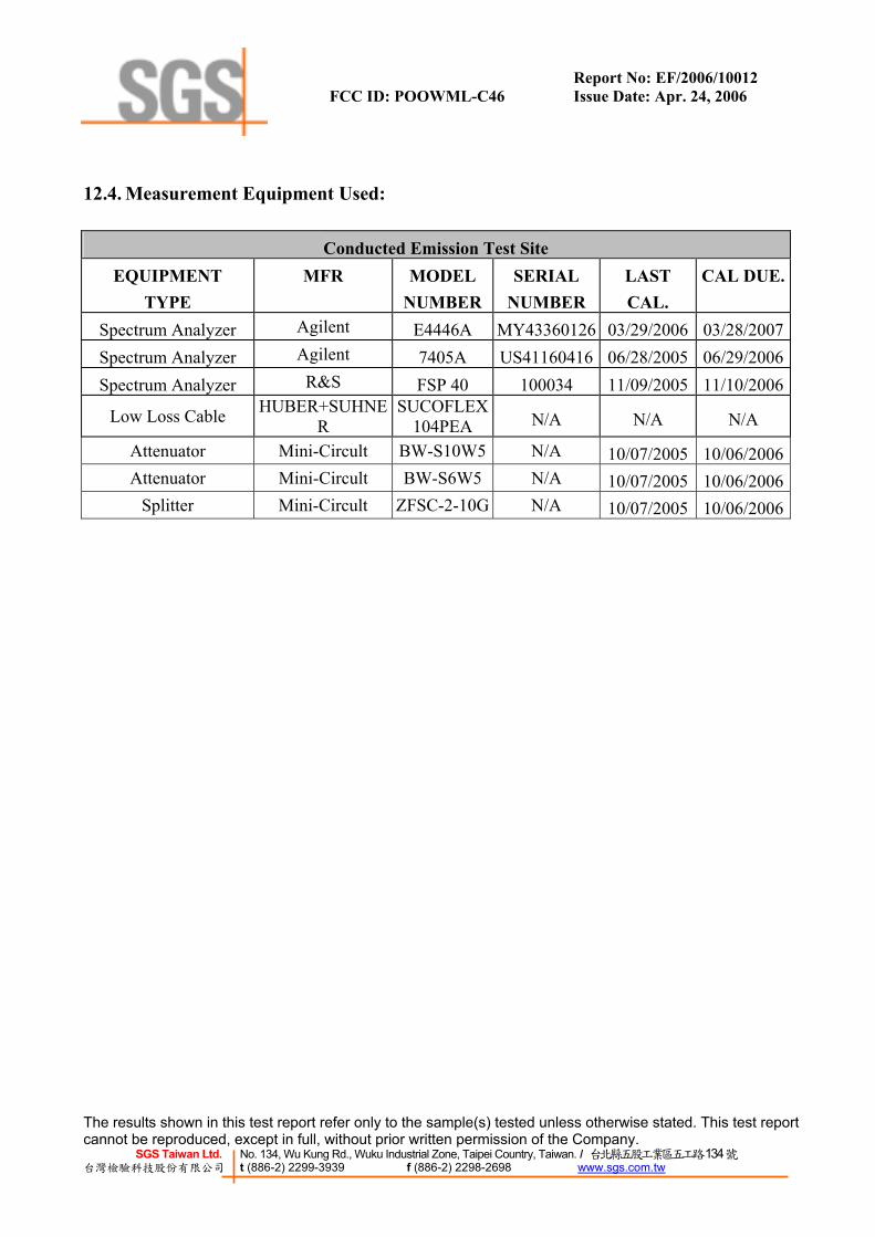
12. TIME OF OCCUPANCY (DWELL TIME) ...............................................................................43 12.1. Standard Applicable ..........................................................................................................................43 12.2. Measurement Procedure....................................................................................................................43 12.3. Measurement Result..........................................................................................................................43 12.4. Measurement Equipment Used: ........................................................................................................44
13. Peak Power Spectral Density ........................................................................................................50 13.1. Standard Applicable ..........................................................................................................................50 13.2. Measurement Procedure....................................................................................................................50 13.3. Measurement Result..........................................................................................................................50 13.4. Measurement Equipment Used: ........................................................................................................50

Report No: EF/2006/10012 FCC ID: POOWML-C46 Issue Date: Apr. 24, 2006
The results shown in this test report refer only to the sample(s) tested unless otherwise stated. This test report cannot be reproduced, except in full, without prior written permission of the Company.
SGS Taiwan Ltd. No. 134, Wu Kung Rd., Wuku Industrial Zone, Taipei Country, Taiwan. / 台北縣五股工業區五工路134號 台灣檢驗科技股份有限公司 t (886-2) 2299-3939 f (886-2) 2298-2698 www.sgs.com.tw
14. ANTENNA REQUIREMENT ......................................................................................................53
14.1. Standard Applicable ..........................................................................................................................53 14.2. Antenna Connected Construction .....................................................................................................53
APPENDIX 1 PHOTOGRPHS OF SET UP ......................................................................................54 APPENDIX 2 PHOTOGRPHS OF EUT............................................................................................56

Report No: EF/2006/10012 FCC ID: POOWML-C46 Issue Date: Apr. 24, 2006
The results shown in this test report refer only to the sample(s) tested unless otherwise stated. This test report cannot be reproduced, except in full, without prior written permission of the Company.
SGS Taiwan Ltd. No. 134, Wu Kung Rd., Wuku Industrial Zone, Taipei Country, Taiwan. / 台北縣五股工業區五工路134號 台灣檢驗科技股份有限公司 t (886-2) 2299-3939 f (886-2) 2298-2698 www.sgs.com.tw
1. GENERAL INFORMATION 1.1. Product Description
The MITSUMI ELECTRIC CO., LTD. Model: WML-C46NBR,WML-C46NHR, WML-C46ABR, WML- C46AHR are Bluetooth Module. The EUT is compliance with Bluetooth Standard. A major technical descriptions of EUT is described as following: A). Operation Frequency: 2402 – 2480MHz, 79 channels B). Rated output power:-1.42dBm C). Modulation type: Frequency Hopping Spread Spectrum (FHSS) D). Antenna Designation: Chip Antenna, 2dBi, Non-User Replaceable (Fixed), refer to an-tenna specification for details. E). Power Supply : 3.3Vdc
1.2. Related Submittal(s) / Grant (s) This submittal(s) (test report) is intended for FCC ID: POOWML-C46 filing to comply with Section 15.247 of the FCC Part 15, Subpart C Rule. The composite system (digital de-vice) is compliance with Subpart B is authorized under a DoC procedure.
1.3. Test Methodology Both conducted and radiated testing were performed according to the procedures in ANSI C63.4 (2003). Radiated testing was performed at an antenna to EUT distance 3 meters.
1.4. Test Facility
The open area test site and conducted measurement facility used to collect the radiated data is located on the address of SGS Taiwan Ltd. No. 134, Wu Kung Rd., Wuku Industrial Zone, Taipei Country, Taiwan. The Open Area Test Sites and the Line Conducted labs are constructed and calibrated to meet the FCC requirements in documents ANSI C63.4: 2003and CISPR 22/EN 55022 requirements. Site No. 1(3 &10 meters) Registration Number: 94644, Both OATS and Anechoic chamber (3 meters) was accredited by CNLA (0513).
1.5. Special Accessories Not available for this EUT intended for grant.
1.6. Equipment Modifications Not available for this EUT intended for grant.
Report No: EF/2006/10012 FCC ID: POOWML-C46 Issue Date: Apr. 24, 2006
The results shown in this test report refer only to the sample(s) tested unless otherwise stated. This test report cannot be reproduced, except in full, without prior written permission of the Company.
SGS Taiwan Ltd. No. 134, Wu Kung Rd., Wuku Industrial Zone, Taipei Country, Taiwan. / 台北縣五股工業區五工路134號 台灣檢驗科技股份有限公司 t (886-2) 2299-3939 f (886-2) 2298-2698 www.sgs.com.tw
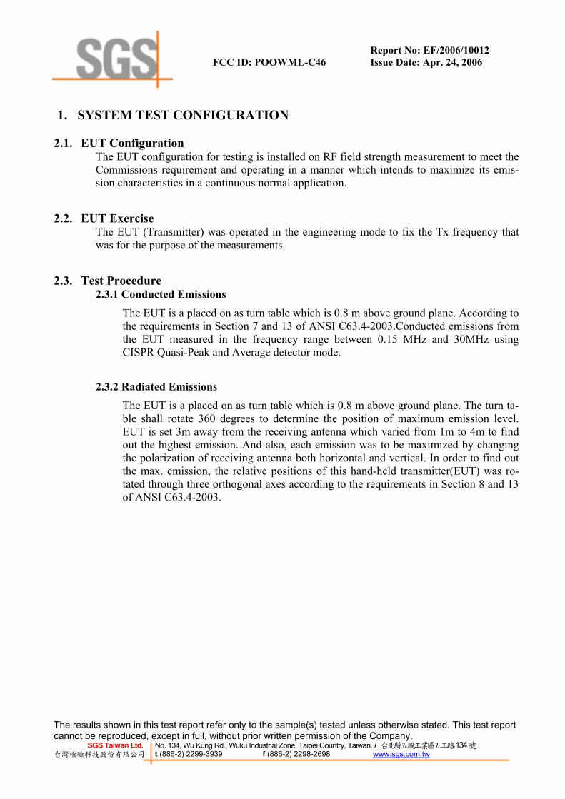
1. SYSTEM TEST CONFIGURATION
2.1. EUT Configuration The EUT configuration for testing is installed on RF field strength measurement to meet the Commissions requirement and operating in a manner which intends to maximize its emis-sion characteristics in a continuous normal application.
2.2. EUT Exercise The EUT (Transmitter) was operated in the engineering mode to fix the Tx frequency that was for the purpose of the measurements.
2.3. Test Procedure 2.3.1 Conducted Emissions
The EUT is a placed on as turn table which is 0.8 m above ground plane. According to the requirements in Section 7 and 13 of ANSI C63.4-2003.Conducted emissions from the EUT measured in the frequency range between 0.15 MHz and 30MHz using CISPR Quasi-Peak and Average detector mode.
2.3.2 Radiated Emissions
The EUT is a placed on as turn table which is 0.8 m above ground plane. The turn ta-ble shall rotate 360 degrees to determine the position of maximum emission level. EUT is set 3m away from the receiving antenna which varied from 1m to 4m to find out the highest emission. And also, each emission was to be maximized by changing the polarization of receiving antenna both horizontal and vertical. In order to find out the max. emission, the relative positions of this hand-held transmitter(EUT) was ro-tated through three orthogonal axes according to the requirements in Section 8 and 13of ANSI C63.4-2003.

Report No: EF/2006/10012 FCC ID: POOWML-C46 Issue Date: Apr. 24, 2006
The results shown in this test report refer only to the sample(s) tested unless otherwise stated. This test report cannot be reproduced, except in full, without prior written permission of the Company.
SGS Taiwan Ltd. No. 134, Wu Kung Rd., Wuku Industrial Zone, Taipei Country, Taiwan. / 台北縣五股工業區五工路134號 台灣檢驗科技股份有限公司 t (886-2) 2299-3939 f (886-2) 2298-2698 www.sgs.com.tw
2.4. Configuration of Tested System
Fig. 2-1 Configuration of Tested System (Fixed channel)
Table 2-1 Equipment Used in Tested System
Item Equipment Mfr/Brand Model/
Type No. FCC ID Series No. Data Cable Power Cord
1. Notebook IBM T40 99HCYF4 R33026 Un-shield Un-shield
2. CASIRA CSR BCES301199/1 7383070403 CASIRA Un-shield Un-shield
3. Test software CSR Bluesuit 1.21 N/A N/A N/A N/A
CASIRA EUT
Notebook
Report No: EF/2006/10012 FCC ID: POOWML-C46 Issue Date: Apr. 24, 2006
The results shown in this test report refer only to the sample(s) tested unless otherwise stated. This test report cannot be reproduced, except in full, without prior written permission of the Company.
SGS Taiwan Ltd. No. 134, Wu Kung Rd., Wuku Industrial Zone, Taipei Country, Taiwan. / 台北縣五股工業區五工路134號 台灣檢驗科技股份有限公司 t (886-2) 2299-3939 f (886-2) 2298-2698 www.sgs.com.tw
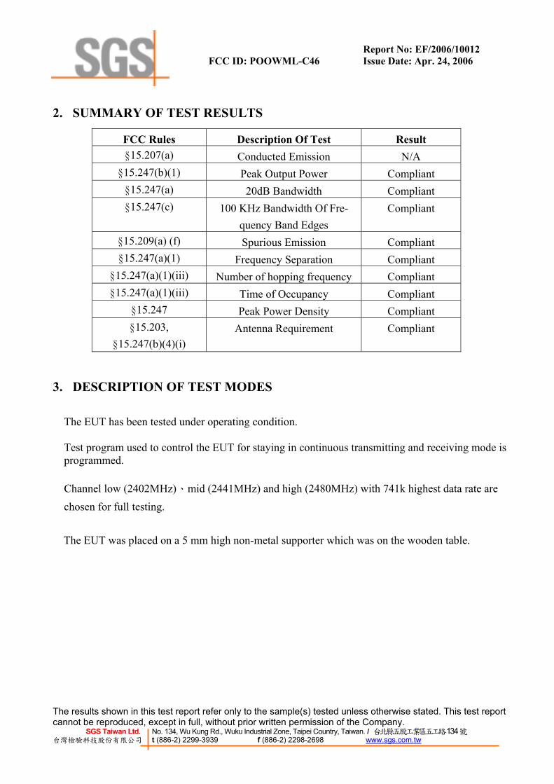
2. SUMMARY OF TEST RESULTS
FCC Rules Description Of Test Result §15.207(a) Conducted Emission N/A
§15.247(b)(1) Peak Output Power Compliant §15.247(a) 20dB Bandwidth Compliant §15.247(c) 100 KHz Bandwidth Of Fre-
quency Band Edges Compliant
§15.209(a) (f) Spurious Emission Compliant §15.247(a)(1) Frequency Separation Compliant
§15.247(a)(1)(iii) Number of hopping frequency Compliant §15.247(a)(1)(iii) Time of Occupancy Compliant
§15.247 Peak Power Density Compliant §15.203,
§15.247(b)(4)(i) Antenna Requirement Compliant
3. DESCRIPTION OF TEST MODES
The EUT has been tested under operating condition. Test program used to control the EUT for staying in continuous transmitting and receiving mode is programmed.
Channel low (2402MHz)、mid (2441MHz) and high (2480MHz) with 741k highest data rate are chosen for full testing. The EUT was placed on a 5 mm high non-metal supporter which was on the wooden table.

Report No: EF/2006/10012 FCC ID: POOWML-C46 Issue Date: Apr. 24, 2006
The results shown in this test report refer only to the sample(s) tested unless otherwise stated. This test report cannot be reproduced, except in full, without prior written permission of the Company.
SGS Taiwan Ltd. No. 134, Wu Kung Rd., Wuku Industrial Zone, Taipei Country, Taiwan. / 台北縣五股工業區五工路134號 台灣檢驗科技股份有限公司 t (886-2) 2299-3939 f (886-2) 2298-2698 www.sgs.com.tw
4. CONDUCTED EMISSION TEST
5.1. Standard Applicable According to §15.207. frequency within 150KHz to 30MHz shall not exceed the limit table as be-low.
Frequency range Limits dB(uV)
MHz Quasi-peak Average 0.15 to 0.50 66 to 56 56 to 46
0.50 to 5 56 46 5 to 30 60 50
Note 1.The lower limit shall apply at the transition frequencies 2.The limit decreases linearly with the logarithm of the frequency in the range 0.15 MHz to 0.50 MHz.
5.2. EUT Setup 1. The conducted emission tests were performed in the test site, using the setup in accordance
with the ANSI C63.4-2003.
2. The EUT was plug-in the AC/DC Power adapter. The host system was placed on the center of the back edge on the test table. The peripherals was placed on the side of the host PC sys-tem. The rear of the EUT and peripherals were placed flushed with the rear of the tabletop.
3. The spacing between the peripherals was 10 centimeters.
4. External I/O cables were draped along the edge of the test table and bundle when necessary.
5. The host system was connected with 110Vac/60Hz power source.
5.3. Measurement Procedure 1. The EUT was placed on a table which is 0.8m above ground plane.
2. Maximum procedure was performed on the six highest emissions to ensure EUT compliance.
3. Repeat above procedures until all frequency measured were complete.
Report No: EF/2006/10012 FCC ID: POOWML-C46 Issue Date: Apr. 24, 2006
The results shown in this test report refer only to the sample(s) tested unless otherwise stated. This test report cannot be reproduced, except in full, without prior written permission of the Company.
SGS Taiwan Ltd. No. 134, Wu Kung Rd., Wuku Industrial Zone, Taipei Country, Taiwan. / 台北縣五股工業區五工路134號 台灣檢驗科技股份有限公司 t (886-2) 2299-3939 f (886-2) 2298-2698 www.sgs.com.tw
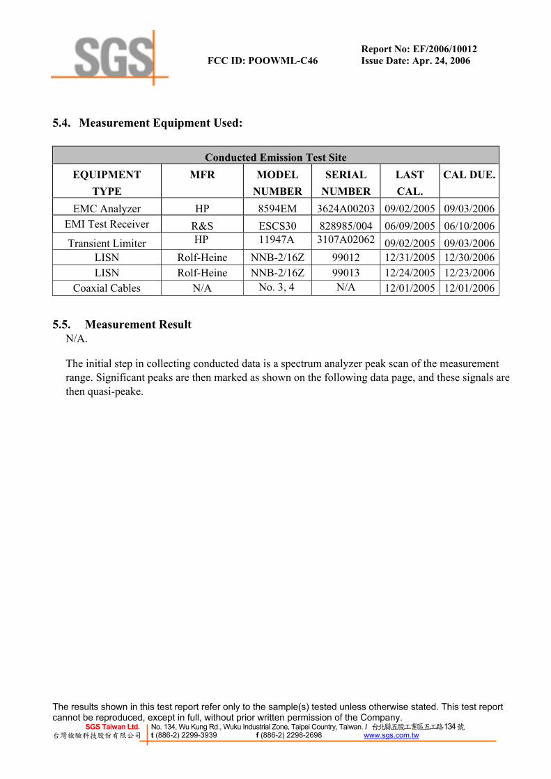
5.4. Measurement Equipment Used:
Conducted Emission Test Site EQUIPMENT
TYPE MFR MODEL
NUMBER SERIAL
NUMBER LAST CAL.
CAL DUE.
EMC Analyzer HP 8594EM 3624A00203 09/02/2005 09/03/2006EMI Test Receiver R&S ESCS30 828985/004 06/09/2005 06/10/2006Transient Limiter HP 11947A 3107A02062 09/02/2005 09/03/2006
LISN Rolf-Heine NNB-2/16Z 99012 12/31/2005 12/30/2006LISN Rolf-Heine NNB-2/16Z 99013 12/24/2005 12/23/2006
Coaxial Cables N/A No. 3, 4 N/A 12/01/2005 12/01/2006
5.5. Measurement Result N/A.
The initial step in collecting conducted data is a spectrum analyzer peak scan of the measurement range. Significant peaks are then marked as shown on the following data page, and these signals are then quasi-peake.

Report No: EF/2006/10012 FCC ID: POOWML-C46 Issue Date: Apr. 24, 2006
The results shown in this test report refer only to the sample(s) tested unless otherwise stated. This test report cannot be reproduced, except in full, without prior written permission of the Company.
SGS Taiwan Ltd. No. 134, Wu Kung Rd., Wuku Industrial Zone, Taipei Country, Taiwan. / 台北縣五股工業區五工路134號 台灣檢驗科技股份有限公司 t (886-2) 2299-3939 f (886-2) 2298-2698 www.sgs.com.tw
5. PEAK OUTPUT POWER MEASUREMENT
6.1. Standard Applicable For frequency hopping systems operating in the 2400-2483.5 MHz band employing at least 75 hopping
channels, and all frequency hopping systems in the 5725-5850MHz band: 1Watt. For all other frequency hopping systems in the 2400 – 2483.5MHz band: 0.125 Watts.
6.2. Measurement Procedure 1. Place the EUT on the table and set it in transmitting mode.
2. Remove the antenna from the EUT and then connect a low loss RF cable from the antenna port to the power meter or spectrum. (Channel power function, RBW, VBW = 1MHz)
3. Record the max. reading.
4. Repeat above procedures until all frequency measured were complete.
6.3. Measurement Result
Frequency(MHz)
Reading Power(dBm) Cable Loss Output Power
(dBm)Output Power
(W)Limit(W)
2402.00 -1.62 0.20 -1.42 0.00072 12441.00 -1.85 0.20 -1.65 0.00068 12480.00 -1.69 0.20 -1.49 0.00071 1
6.4. Measurement Equipment Used:
Conducted Emission Test Site EQUIPMENT
TYPE MFR MODEL
NUMBERSERIAL
NUMBER LAST CAL.
CAL DUE.
Spectrum Analyzer Agilent E4446A MY43360126 03/29/2006 03/28/2007Spectrum Analyzer Agilent 7405A US41160416 06/28/2005 06/29/2006Spectrum Analyzer R&S FSP 40 100034 11/09/2005 11/10/2006
Low Loss Cable HUBER+SUHNER
SUCOFLEX 104PEA N/A N/A N/A
Attenuator Mini-Circult BW-S10W5 N/A 10/07/2005 10/06/2006Attenuator Mini-Circult BW-S6W5 N/A 10/07/2005 10/06/2006
Splitter Mini-Circult ZFSC-2-10G N/A 10/07/2005 10/06/2006

Report No: EF/2006/10012 FCC ID: POOWML-C46 Issue Date: Apr. 24, 2006
The results shown in this test report refer only to the sample(s) tested unless otherwise stated. This test report cannot be reproduced, except in full, without prior written permission of the Company.
SGS Taiwan Ltd. No. 134, Wu Kung Rd., Wuku Industrial Zone, Taipei Country, Taiwan. / 台北縣五股工業區五工路134號 台灣檢驗科技股份有限公司 t (886-2) 2299-3939 f (886-2) 2298-2698 www.sgs.com.tw
Peak Power Output Data Plot (CH Low)
Peak Power Output Data Plot (CH Mid)

Report No: EF/2006/10012 FCC ID: POOWML-C46 Issue Date: Apr. 24, 2006
The results shown in this test report refer only to the sample(s) tested unless otherwise stated. This test report cannot be reproduced, except in full, without prior written permission of the Company.
SGS Taiwan Ltd. No. 134, Wu Kung Rd., Wuku Industrial Zone, Taipei Country, Taiwan. / 台北縣五股工業區五工路134號 台灣檢驗科技股份有限公司 t (886-2) 2299-3939 f (886-2) 2298-2698 www.sgs.com.tw
Peak Power Output Data Plot (CH High)
Report No: EF/2006/10012 FCC ID: POOWML-C46 Issue Date: Apr. 24, 2006
The results shown in this test report refer only to the sample(s) tested unless otherwise stated. This test report cannot be reproduced, except in full, without prior written permission of the Company.
SGS Taiwan Ltd. No. 134, Wu Kung Rd., Wuku Industrial Zone, Taipei Country, Taiwan. / 台北縣五股工業區五工路134號 台灣檢驗科技股份有限公司 t (886-2) 2299-3939 f (886-2) 2298-2698 www.sgs.com.tw
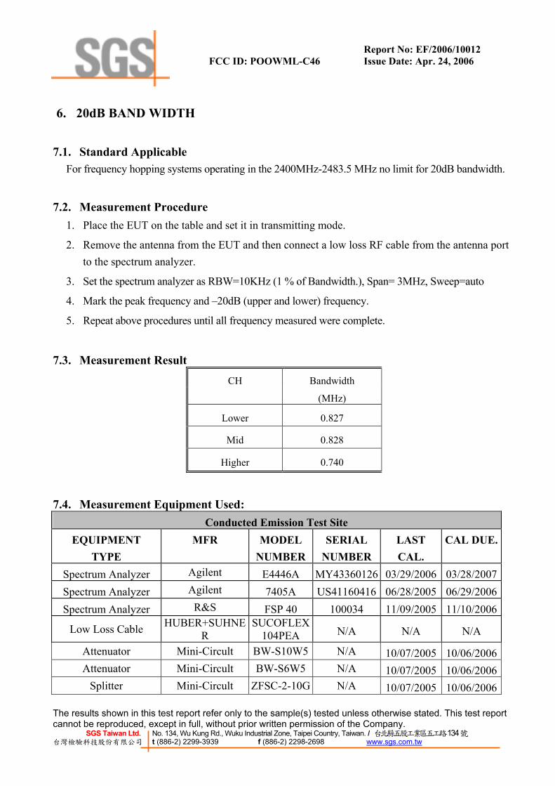
6. 20dB BAND WIDTH
7.1. Standard Applicable For frequency hopping systems operating in the 2400MHz-2483.5 MHz no limit for 20dB bandwidth.
7.2. Measurement Procedure 1. Place the EUT on the table and set it in transmitting mode.
2. Remove the antenna from the EUT and then connect a low loss RF cable from the antenna port to the spectrum analyzer.
3. Set the spectrum analyzer as RBW=10KHz (1 % of Bandwidth.), Span= 3MHz, Sweep=auto
4. Mark the peak frequency and –20dB (upper and lower) frequency.
5. Repeat above procedures until all frequency measured were complete.
7.3. Measurement Result
CH Bandwidth
(MHz)
Lower 0.827
Mid 0.828
Higher 0.740
7.4. Measurement Equipment Used: Conducted Emission Test Site
EQUIPMENT TYPE
MFR MODEL NUMBER
SERIAL NUMBER
LAST CAL.
CAL DUE.
Spectrum Analyzer Agilent E4446A MY43360126 03/29/2006 03/28/2007Spectrum Analyzer Agilent 7405A US41160416 06/28/2005 06/29/2006Spectrum Analyzer R&S FSP 40 100034 11/09/2005 11/10/2006
Low Loss Cable HUBER+SUHNER
SUCOFLEX 104PEA N/A N/A N/A
Attenuator Mini-Circult BW-S10W5 N/A 10/07/2005 10/06/2006Attenuator Mini-Circult BW-S6W5 N/A 10/07/2005 10/06/2006
Splitter Mini-Circult ZFSC-2-10G N/A 10/07/2005 10/06/2006

Report No: EF/2006/10012 FCC ID: POOWML-C46 Issue Date: Apr. 24, 2006
The results shown in this test report refer only to the sample(s) tested unless otherwise stated. This test report cannot be reproduced, except in full, without prior written permission of the Company.
SGS Taiwan Ltd. No. 134, Wu Kung Rd., Wuku Industrial Zone, Taipei Country, Taiwan. / 台北縣五股工業區五工路134號 台灣檢驗科技股份有限公司 t (886-2) 2299-3939 f (886-2) 2298-2698 www.sgs.com.tw
20dB Band Width Test Data CH-Low
20dB Band Width Test Data CH-Mid

Report No: EF/2006/10012 FCC ID: POOWML-C46 Issue Date: Apr. 24, 2006
The results shown in this test report refer only to the sample(s) tested unless otherwise stated. This test report cannot be reproduced, except in full, without prior written permission of the Company.
SGS Taiwan Ltd. No. 134, Wu Kung Rd., Wuku Industrial Zone, Taipei Country, Taiwan. / 台北縣五股工業區五工路134號 台灣檢驗科技股份有限公司 t (886-2) 2299-3939 f (886-2) 2298-2698 www.sgs.com.tw
20dB Band Width Test Data CH-High

Report No: EF/2006/10012 FCC ID: POOWML-C46 Issue Date: Apr. 24, 2006
The results shown in this test report refer only to the sample(s) tested unless otherwise stated. This test report cannot be reproduced, except in full, without prior written permission of the Company.
SGS Taiwan Ltd. No. 134, Wu Kung Rd., Wuku Industrial Zone, Taipei Country, Taiwan. / 台北縣五股工業區五工路134號 台灣檢驗科技股份有限公司 t (886-2) 2299-3939 f (886-2) 2298-2698 www.sgs.com.tw
7. 100KHz BANDWIDTH OF BAND EDGES MEASUREMENT
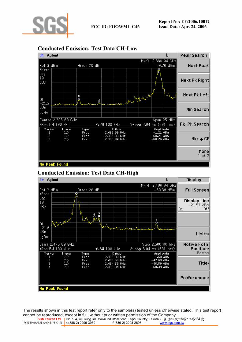
8.1. Standard Applicable According to §15.247(c), in any 100 KHz bandwidth outside the frequency bands in which the spread spectrum intentional radiator in operating, the radio frequency power that is produced by the intentional radiator shall be at least 20dB below that in the 100KHz bandwidth within the band that contains the highest level of the desired power, In addition, radiated emissions which fall in the restricted bands, as defined in §15.205(a), must also comply with the radiated emission limits specified in15.209(a).
8.2. Measurement Procedure 1. Place the EUT on the table and set it in transmitting mode. 2. Remove the antenna from the EUT and then connect a low loss RF cable from the antenna port
to the spectrum analyzer. 3. Set center frequency of spectrum analyzer = operating frequency. 4. Set the spectrum analyzer as RBW, VBW=100KHz, Span=25MHz, Sweep = auto 5. Mark Peak, 2.390GHz and 2.4835GHz and record the max. level. 6. Repeat above procedures until all frequency measured were complete. 7. Radiated Emission refer to section 9.
8.3. Measurement Result Refer to attach spectrum analyzer data chart.
8.4. Measurement Equipment Used:
Conducted Emission Test Site EQUIPMENT
TYPE MFR MODEL
NUMBERSERIAL
NUMBER LAST CAL.
CAL DUE.
Spectrum Analyzer Agilent E4446A MY43360126 03/29/2006 03/28/2007Spectrum Analyzer Agilent 7405A US41160416 06/28/2005 06/29/2006Spectrum Analyzer R&S FSP 40 100034 11/09/2005 11/10/2006
Low Loss Cable HUBER+SUHNER
SUCOFLEX 104PEA N/A N/A N/A
Attenuator Mini-Circult BW-S10W5 N/A 10/07/2005 10/06/2006Attenuator Mini-Circult BW-S6W5 N/A 10/07/2005 10/06/2006
Splitter Mini-Circult ZFSC-2-10G N/A 10/07/2005 10/06/2006Note: Measurement Equipment for radiated emission refers to section 9.
Report No: EF/2006/10012 FCC ID: POOWML-C46 Issue Date: Apr. 24, 2006
The results shown in this test report refer only to the sample(s) tested unless otherwise stated. This test report cannot be reproduced, except in full, without prior written permission of the Company.
SGS Taiwan Ltd. No. 134, Wu Kung Rd., Wuku Industrial Zone, Taipei Country, Taiwan. / 台北縣五股工業區五工路134號 台灣檢驗科技股份有限公司 t (886-2) 2299-3939 f (886-2) 2298-2698 www.sgs.com.tw
Conducted Emission: Test Data CH-Low
Conducted Emission: Test Data CH-High

Report No: EF/2006/10012 FCC ID: POOWML-C46 Issue Date: Apr. 24, 2006
The results shown in this test report refer only to the sample(s) tested unless otherwise stated. This test report cannot be reproduced, except in full, without prior written permission of the Company.
SGS Taiwan Ltd. No. 134, Wu Kung Rd., Wuku Industrial Zone, Taipei Country, Taiwan. / 台北縣五股工業區五工路134號 台灣檢驗科技股份有限公司 t (886-2) 2299-3939 f (886-2) 2298-2698 www.sgs.com.tw
Radiated Emission: Operation Mode TX CH Low Test Date Apr. 17, 2006 Fundamental Frequency 2402 MHz Test By Danny Temperature 25 ℃ Pol Ver. Humidity 65 %
Peak AV Peak AV
Freq. Reading Reading Ant./CL Peak AV Limit Limit Margin Remark(MHz) (dBuV) (dBuV) CF(dB) (dBuV/m) (dBuV/m) (dBuV/m)(dBuV/m) (dB)2351.7 32.41 ---- -3.58 28.83 ---- 74.00 54.00 -25.17 Peak2354.1 33.10 ---- -3.58 29.52 ---- 75.00 55.00 -25.48 Peak2386.0 32.96 ---- -3.43 29.53 ---- 76.00 56.00 -26.47 Peak2390.0 31.96 ---- -3.40 28.56 ---- 77.00 57.00 -28.44 Peak
Actual FS
Operation Mode TX CH Low Test Date Apr. 17, 2006 Fundamental Frequency 2402 MHz Test By Danny Temperature 25 ℃ Pol Hor. Humidity 65 %
Peak AV Peak AV
Freq. Reading Reading Ant./CL Peak AV Limit Limit Margin Remark(MHz) (dBuV) (dBuV) CF(dB) (dBuV/m) (dBuV/m) (dBuV/m)(dBuV/m) (dB)2351.7 32.20 ---- -3.58 28.62 ---- 74.00 54.00 -25.38 Peak2354.1 31.91 ---- -3.58 28.33 ---- 75.00 55.00 -26.67 Peak2386.0 31.80 ---- -3.43 28.37 ---- 76.00 56.00 -27.63 Peak2390.0 31.41 ---- -3.40 28.01 ---- 77.00 57.00 -28.99 Peak
Actual FS
Remark: (1) Datas of measurement within this frequency range shown “ - ” in the table above means
the reading of emissions are attenuated more than 20dB below the permissible limits or the field strength is too small to be measured.
(2) Radiated emissions measured in frequency above 1000MHz were made with an instru-ment using Peak detector mode and average detector mode of the emission shown in Ac-tual FS column。
(3) Spectrum Peak Setting : 1GHz- 26GHz, RBW= 1MHz, VBW= 3MHz, Sweep time= 200 ms.
(4) Spectrum AV Setting : 1GHz- 26GHz, RBW= 1MHz, VBW= 10Hz, Sweep time= 200 ms.
Report No: EF/2006/10012 FCC ID: POOWML-C46 Issue Date: Apr. 24, 2006
The results shown in this test report refer only to the sample(s) tested unless otherwise stated. This test report cannot be reproduced, except in full, without prior written permission of the Company.
SGS Taiwan Ltd. No. 134, Wu Kung Rd., Wuku Industrial Zone, Taipei Country, Taiwan. / 台北縣五股工業區五工路134號 台灣檢驗科技股份有限公司 t (886-2) 2299-3939 f (886-2) 2298-2698 www.sgs.com.tw
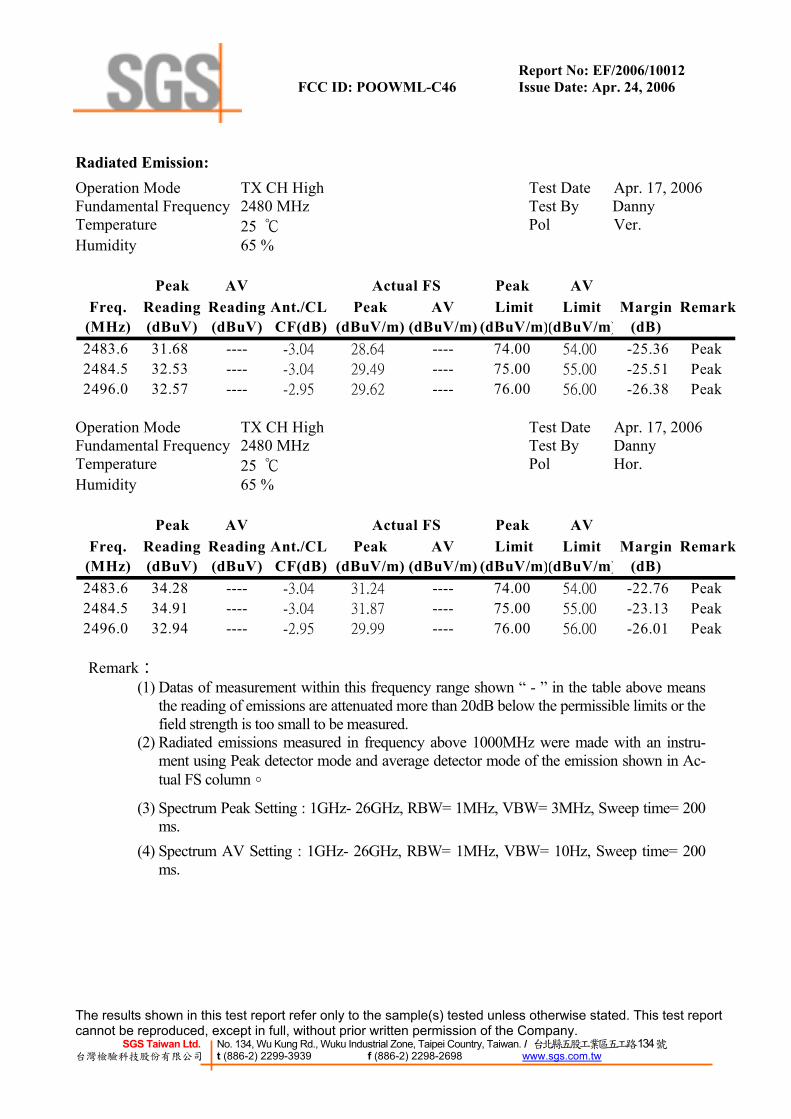
Radiated Emission: Operation Mode TX CH High Test Date Apr. 17, 2006 Fundamental Frequency 2480 MHz Test By Danny Temperature 25 ℃ Pol Ver. Humidity 65 %
Peak AV Peak AV
Freq. Reading Reading Ant./CL Peak AV Limit Limit Margin Remark(MHz) (dBuV) (dBuV) CF(dB) (dBuV/m) (dBuV/m) (dBuV/m)(dBuV/m) (dB)2483.6 31.68 ---- -3.04 28.64 ---- 74.00 54.00 -25.36 Peak2484.5 32.53 ---- -3.04 29.49 ---- 75.00 55.00 -25.51 Peak2496.0 32.57 ---- -2.95 29.62 ---- 76.00 56.00 -26.38 Peak
Actual FS
Operation Mode TX CH High Test Date Apr. 17, 2006 Fundamental Frequency 2480 MHz Test By Danny Temperature 25 ℃ Pol Hor. Humidity 65 %
Peak AV Peak AV
Freq. Reading Reading Ant./CL Peak AV Limit Limit Margin Remark(MHz) (dBuV) (dBuV) CF(dB) (dBuV/m) (dBuV/m) (dBuV/m)(dBuV/m) (dB)2483.6 34.28 ---- -3.04 31.24 ---- 74.00 54.00 -22.76 Peak2484.5 34.91 ---- -3.04 31.87 ---- 75.00 55.00 -23.13 Peak2496.0 32.94 ---- -2.95 29.99 ---- 76.00 56.00 -26.01 Peak
Actual FS
Remark:
(1) Datas of measurement within this frequency range shown “ - ” in the table above means the reading of emissions are attenuated more than 20dB below the permissible limits or the field strength is too small to be measured.
(2) Radiated emissions measured in frequency above 1000MHz were made with an instru-ment using Peak detector mode and average detector mode of the emission shown in Ac-tual FS column。
(3) Spectrum Peak Setting : 1GHz- 26GHz, RBW= 1MHz, VBW= 3MHz, Sweep time= 200 ms.
(4) Spectrum AV Setting : 1GHz- 26GHz, RBW= 1MHz, VBW= 10Hz, Sweep time= 200 ms.

Report No: EF/2006/10012 FCC ID: POOWML-C46 Issue Date: Apr. 24, 2006
The results shown in this test report refer only to the sample(s) tested unless otherwise stated. This test report cannot be reproduced, except in full, without prior written permission of the Company.
SGS Taiwan Ltd. No. 134, Wu Kung Rd., Wuku Industrial Zone, Taipei Country, Taiwan. / 台北縣五股工業區五工路134號 台灣檢驗科技股份有限公司 t (886-2) 2299-3939 f (886-2) 2298-2698 www.sgs.com.tw
8. SPURIOUS RADIATED EMISSION TEST
9.1. Standard Applicable According to §15.247(c), all other emissions outside these bands shall not exceed the general radiated emission limits specified in §15.209(a). And according to §15.33(a)(1), for an intentional radiator op-erates below 10GHz, the frequency range of measurements: to the tenth harmonic of the highest funda-mental frequency or to 40GHz, whichever is lower.
9.2. EUT Setup 1. The radiated emission tests were performed in the 3 meter open-test site, using the setup in ac-
cordance with the ANSI C63.4-2003. 2. The EUT was put in the front of the test table. The peripherals was placed on the side of the
host system. The rear of the EUT and peripherals were placed flushed with the rear of the ta-bletop.
3. The spacing between the peripherals was 10 centimeters. 4. External I/O cables were draped along the edge of the test table and bundle when necessary. 5. The host PC system was connected with 110Vac/60Hz power source.
9.3. Measurement Procedure 1. The EUT was placed on a turn table which is 0.8m above ground plane. 2. The turn table shall rotate 360 degrees to determine the position of maximum emission level. 3. EUT is set 3m away from the receiving antenna which varied from 1m to 4m to find out the
highest emissions. 4. Maximum procedure was performed on the six highest emissions to ensure EUT compliance. 5. And also, each emission was to be maximized by changing the polarization of receiving
antenna both horizontal and vertical. 6. Repeat above procedures until all frequency measured were complete.

Report No: EF/2006/10012 FCC ID: POOWML-C46 Issue Date: Apr. 24, 2006
The results shown in this test report refer only to the sample(s) tested unless otherwise stated. This test report cannot be reproduced, except in full, without prior written permission of the Company.
SGS Taiwan Ltd. No. 134, Wu Kung Rd., Wuku Industrial Zone, Taipei Country, Taiwan. / 台北縣五股工業區五工路134號 台灣檢驗科技股份有限公司 t (886-2) 2299-3939 f (886-2) 2298-2698 www.sgs.com.tw
9.4. Test SET-UP (Block Diagram of Configuration)
(A) Radiated Emission Test Set-Up, Frequency Below 1000MHz
(B) Radiated Emission Test Set-UP Frequency Over 1 GHz
1m to 4m
Spectrum Analyzer
EUT
3m
0.8m
Turntable
Coaxial Cable Ground Plane
Test Receiver
EUT3m
1m to 4m
Turntable
Coaxial CableGround Plane
0.8m
Report No: EF/2006/10012 FCC ID: POOWML-C46 Issue Date: Apr. 24, 2006
The results shown in this test report refer only to the sample(s) tested unless otherwise stated. This test report cannot be reproduced, except in full, without prior written permission of the Company.
SGS Taiwan Ltd. No. 134, Wu Kung Rd., Wuku Industrial Zone, Taipei Country, Taiwan. / 台北縣五股工業區五工路134號 台灣檢驗科技股份有限公司 t (886-2) 2299-3939 f (886-2) 2298-2698 www.sgs.com.tw
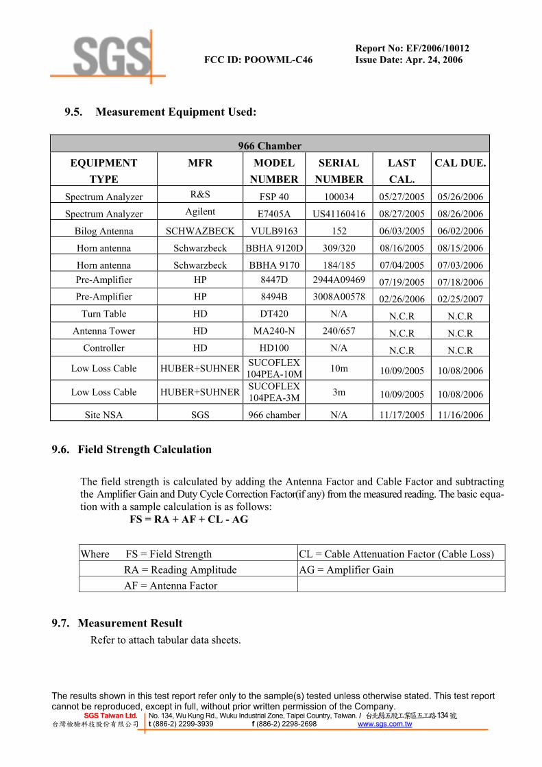
9.5. Measurement Equipment Used:
966 Chamber EQUIPMENT
TYPE MFR MODEL
NUMBERSERIAL
NUMBER LAST CAL.
CAL DUE.
Spectrum Analyzer R&S FSP 40 100034 05/27/2005 05/26/2006
Spectrum Analyzer Agilent E7405A US41160416 08/27/2005 08/26/2006
Bilog Antenna SCHWAZBECK VULB9163 152 06/03/2005 06/02/2006
Horn antenna Schwarzbeck BBHA 9120D 309/320 08/16/2005 08/15/2006
Horn antenna Schwarzbeck BBHA 9170 184/185 07/04/2005 07/03/2006Pre-Amplifier HP 8447D 2944A09469 07/19/2005 07/18/2006Pre-Amplifier HP 8494B 3008A00578 02/26/2006 02/25/2007
Turn Table HD DT420 N/A N.C.R N.C.R Antenna Tower HD MA240-N 240/657 N.C.R N.C.R
Controller HD HD100 N/A N.C.R N.C.R
Low Loss Cable HUBER+SUHNER SUCOFLEX 104PEA-10M 10m 10/09/2005 10/08/2006
Low Loss Cable HUBER+SUHNER SUCOFLEX 104PEA-3M 3m 10/09/2005 10/08/2006
Site NSA SGS 966 chamber N/A 11/17/2005 11/16/2006
9.6. Field Strength Calculation
The field strength is calculated by adding the Antenna Factor and Cable Factor and subtracting the Amplifier Gain and Duty Cycle Correction Factor(if any) from the measured reading. The basic equa-tion with a sample calculation is as follows: FS = RA + AF + CL - AG
Where FS = Field Strength CL = Cable Attenuation Factor (Cable Loss) RA = Reading Amplitude AG = Amplifier Gain AF = Antenna Factor
9.7. Measurement Result Refer to attach tabular data sheets.

Report No: EF/2006/10012 FCC ID: POOWML-C46 Issue Date: Apr. 24, 2006
The results shown in this test report refer only to the sample(s) tested unless otherwise stated. This test report cannot be reproduced, except in full, without prior written permission of the Company.
SGS Taiwan Ltd. No. 134, Wu Kung Rd., Wuku Industrial Zone, Taipei Country, Taiwan. / 台北縣五股工業區五工路134號 台灣檢驗科技股份有限公司 t (886-2) 2299-3939 f (886-2) 2298-2698 www.sgs.com.tw
Conducted Spurious Emission Measurement Result Ch Low 30MHz – 3GHz
Ch Low 3GHz – 26.5GHz

Report No: EF/2006/10012 FCC ID: POOWML-C46 Issue Date: Apr. 24, 2006
The results shown in this test report refer only to the sample(s) tested unless otherwise stated. This test report cannot be reproduced, except in full, without prior written permission of the Company.
SGS Taiwan Ltd. No. 134, Wu Kung Rd., Wuku Industrial Zone, Taipei Country, Taiwan. / 台北縣五股工業區五工路134號 台灣檢驗科技股份有限公司 t (886-2) 2299-3939 f (886-2) 2298-2698 www.sgs.com.tw
Ch Mid 30MHz – 3GHz
Ch Mid 3GHz – 26.5GHz

Report No: EF/2006/10012 FCC ID: POOWML-C46 Issue Date: Apr. 24, 2006
The results shown in this test report refer only to the sample(s) tested unless otherwise stated. This test report cannot be reproduced, except in full, without prior written permission of the Company.
SGS Taiwan Ltd. No. 134, Wu Kung Rd., Wuku Industrial Zone, Taipei Country, Taiwan. / 台北縣五股工業區五工路134號 台灣檢驗科技股份有限公司 t (886-2) 2299-3939 f (886-2) 2298-2698 www.sgs.com.tw
Ch High 30MHz – 3GHz
Ch High 3GHz – 26.5GHz

Report No: EF/2006/10012 FCC ID: POOWML-C46 Issue Date: Apr. 24, 2006
The results shown in this test report refer only to the sample(s) tested unless otherwise stated. This test report cannot be reproduced, except in full, without prior written permission of the Company.
SGS Taiwan Ltd. No. 134, Wu Kung Rd., Wuku Industrial Zone, Taipei Country, Taiwan. / 台北縣五股工業區五工路134號 台灣檢驗科技股份有限公司 t (886-2) 2299-3939 f (886-2) 2298-2698 www.sgs.com.tw
Radiated Spurious Emission Measurement Result (below 1GHz) Operation Mode TX CH Low Test Date Apr. 18, 2006 Fundamental Frequency 2402MHz Test By Danny Temperature 25 ℃ Pol Ver./Hor. Humidity 65 %
Freq. Ant.Pol. Detector
Mode Reading Factor Actual FS Limit3m Safe Margin
(MHz) H/V (PK/QP) (dBuV) (dB) (dBuV/m) (dBuV/m) (dB)30.97 V Peak 40.84 -15.25 25.59 40.00 -14.41
320.03 V Peak 40.97 -12.80 28.17 46.00 -17.83499.48 V Peak 40.77 -9.30 31.47 46.00 -14.53
65.89 H Peak 42.23 -15.35 26.88 40.00 -13.12300.63 H Peak 50.09 -13.37 36.72 46.00 -9.28499.48 H Peak 42.98 -9.30 33.68 46.00 -12.32599.39 H Peak 40.41 -7.64 32.77 46.00 -13.23
Remark:
(1) Measuring frequencies from 30 MHz to the 1GHz。
(2) Radiated emissions measured in frequency range from 30 MHz to 1000MHz were made with an instrument using Peak/QP detector mode.
(3) Datas of measurement within this frequency range shown “ - ” in the table above means the reading of emissions are attenuated more than 20dB below the permissible limits or the field strength is too small to be measured.
(4) The IF bandwidth of SPA between 30MHz to 1GHz was 100KHz.
Report No: EF/2006/10012 FCC ID: POOWML-C46 Issue Date: Apr. 24, 2006
The results shown in this test report refer only to the sample(s) tested unless otherwise stated. This test report cannot be reproduced, except in full, without prior written permission of the Company.
SGS Taiwan Ltd. No. 134, Wu Kung Rd., Wuku Industrial Zone, Taipei Country, Taiwan. / 台北縣五股工業區五工路134號 台灣檢驗科技股份有限公司 t (886-2) 2299-3939 f (886-2) 2298-2698 www.sgs.com.tw
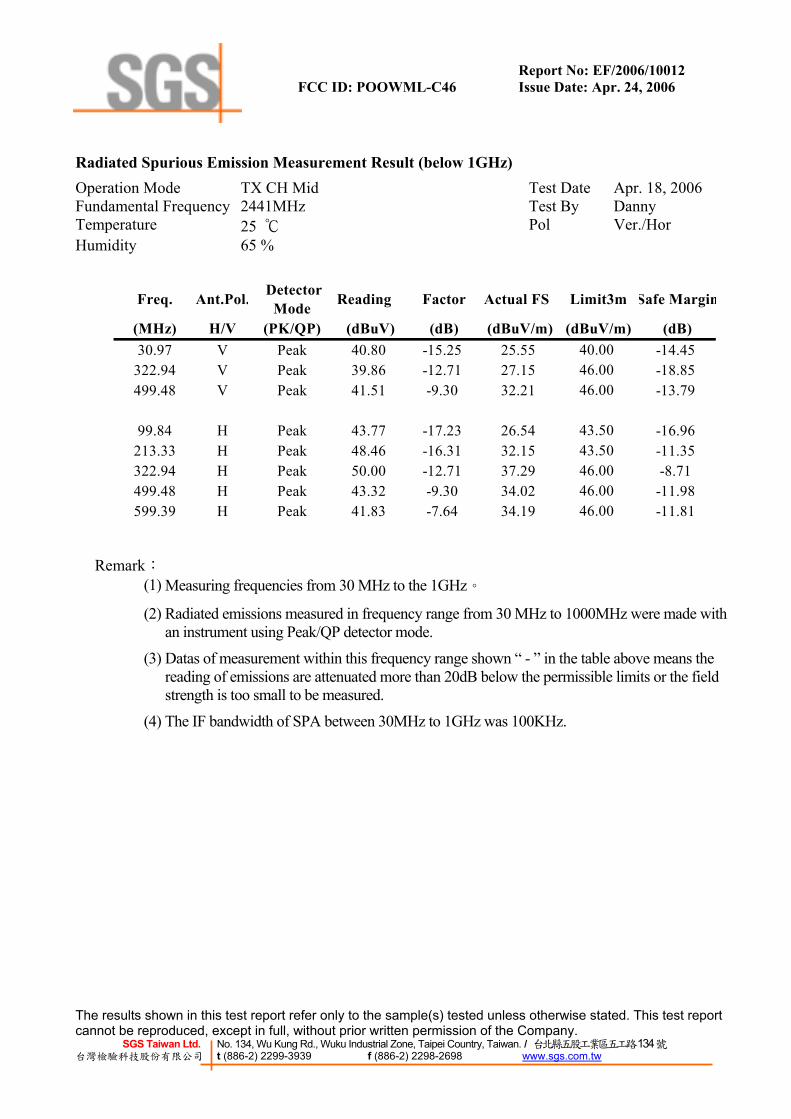
Radiated Spurious Emission Measurement Result (below 1GHz) Operation Mode TX CH Mid Test Date Apr. 18, 2006 Fundamental Frequency 2441MHz Test By Danny Temperature 25 ℃ Pol Ver./Hor Humidity 65 %
Freq. Ant.Pol. DetectorMode Reading Factor Actual FS Limit3m Safe Margin
(MHz) H/V (PK/QP) (dBuV) (dB) (dBuV/m) (dBuV/m) (dB)30.97 V Peak 40.80 -15.25 25.55 40.00 -14.45
322.94 V Peak 39.86 -12.71 27.15 46.00 -18.85499.48 V Peak 41.51 -9.30 32.21 46.00 -13.79
99.84 H Peak 43.77 -17.23 26.54 43.50 -16.96213.33 H Peak 48.46 -16.31 32.15 43.50 -11.35322.94 H Peak 50.00 -12.71 37.29 46.00 -8.71499.48 H Peak 43.32 -9.30 34.02 46.00 -11.98599.39 H Peak 41.83 -7.64 34.19 46.00 -11.81
Remark:
(1) Measuring frequencies from 30 MHz to the 1GHz。
(2) Radiated emissions measured in frequency range from 30 MHz to 1000MHz were made with an instrument using Peak/QP detector mode.
(3) Datas of measurement within this frequency range shown “ - ” in the table above means the reading of emissions are attenuated more than 20dB below the permissible limits or the field strength is too small to be measured.
(4) The IF bandwidth of SPA between 30MHz to 1GHz was 100KHz.

Report No: EF/2006/10012 FCC ID: POOWML-C46 Issue Date: Apr. 24, 2006
The results shown in this test report refer only to the sample(s) tested unless otherwise stated. This test report cannot be reproduced, except in full, without prior written permission of the Company.
SGS Taiwan Ltd. No. 134, Wu Kung Rd., Wuku Industrial Zone, Taipei Country, Taiwan. / 台北縣五股工業區五工路134號 台灣檢驗科技股份有限公司 t (886-2) 2299-3939 f (886-2) 2298-2698 www.sgs.com.tw
Radiated Spurious Emission Measurement Result (below 1GHz) Operation Mode TX CH High Test Date Apr. 18, 2006 Fundamental Frequency 2480MHz Test By Danny Temperature 25 ℃ Pol Ver./Hor Humidity 65 %
Freq. Ant.Pol. DetectorMode Reading Factor Actual FS Limit3m Safe Margin
(MHz) H/V (PK/QP) (dBuV) (dB) (dBuV/m) (dBuV/m) (dB)65.89 V Peak 40.79 -15.35 25.44 40.00 -14.56
320.03 V Peak 40.03 -12.80 27.23 46.00 -18.77499.48 V Peak 41.16 -9.30 31.86 46.00 -14.14
213.33 H Peak 49.42 -16.31 33.11 43.50 -10.39300.63 H Peak 48.65 -13.37 35.28 46.00 -10.72499.48 H Peak 42.96 -9.30 33.66 46.00 -12.34599.39 H Peak 40.36 -7.64 32.72 46.00 -13.28
Remark:
(1) Measuring frequencies from 30 MHz to the 1GHz。
(2) Radiated emissions measured in frequency range from 30 MHz to 1000MHz were made with an instrument using Peak/QP detector mode.
(3) Datas of measurement within this frequency range shown “ - ” in the table above means the reading of emissions are attenuated more than 20dB below the permissible limits or the field strength is too small to be measured.
(4) The IF bandwidth of SPA between 30MHz to 1GHz was 100KHz.

Report No: EF/2006/10012 FCC ID: POOWML-C46 Issue Date: Apr. 24, 2006
The results shown in this test report refer only to the sample(s) tested unless otherwise stated. This test report cannot be reproduced, except in full, without prior written permission of the Company.
SGS Taiwan Ltd. No. 134, Wu Kung Rd., Wuku Industrial Zone, Taipei Country, Taiwan. / 台北縣五股工業區五工路134號 台灣檢驗科技股份有限公司 t (886-2) 2299-3939 f (886-2) 2298-2698 www.sgs.com.tw
Radiated Spurious Emission Measurement Result (above 1GHz) Operation Mode TX CH Low Test Date Apr. 19, 2006 Fundamental Frequency 2402 MHz Test By Danny Temperature 25 ℃ Pol Ver. Humidity 65 %
Peak AV Peak AV
Freq. Reading ReadingAnt./CL Peak AV Limit Limit Margin(MHz) (dBuV) (dBuV) CF(dB) (dBuV/m)(dBuV/m)(dBuV/m)(dBuV/m) (dB)1598.0 ----4804.0 ----7206.0 ----9608.0 ----
12010.0 ----14412.0 ----16814.0 ----19216.0 ----21618.0 ----24020.0 ----
Actual FS
Remark: (1) Measuring frequencies from 1GHz to the 10th harmonic of highest fundamental frequency。
(2) Datas of measurement within this frequency range shown “ - ” in the table above means the reading of emissions are attenuated more than 20dB below the permissible limits or the field strength is too small to be measured.
(3) Radiated emissions measured in frequency above 1000MHz were made with an instrument using Peak detector mode and average detector mode of the emission shown in Actual FScolumn。
(4) Spectrum Peak Setting : 1GHz- 26GHz, RBW= 1MHz, VBW= 3MHz, Sweep time= 200 ms.
(5) Spectrum AV Setting : 1GHz- 26GHz, RBW= 1MHz, VBW= 10Hz, Sweep time= 200 ms.

Report No: EF/2006/10012 FCC ID: POOWML-C46 Issue Date: Apr. 24, 2006
The results shown in this test report refer only to the sample(s) tested unless otherwise stated. This test report cannot be reproduced, except in full, without prior written permission of the Company.
SGS Taiwan Ltd. No. 134, Wu Kung Rd., Wuku Industrial Zone, Taipei Country, Taiwan. / 台北縣五股工業區五工路134號 台灣檢驗科技股份有限公司 t (886-2) 2299-3939 f (886-2) 2298-2698 www.sgs.com.tw
Radiated Spurious Emission Measurement Result (above 1GHz) Operation Mode TX CH Low Test Date Apr. 19, 2006 Fundamental Frequency 2402 MHz Test By Danny Temperature 25 ℃ Pol Hor Humidity 65 %
Peak AV Peak AVFreq. Reading ReadingAnt./CL Peak AV Limit Limit Margin
(MHz) (dBuV) (dBuV) CF(dB) (dBuV/m)(dBuV/m)(dBuV/m)(dBuV/m) (dB)1598.0 ----4804.0 ----7206.0 ----9608.0 ----
12010.0 ----14412.0 ----16814.0 ----19216.0 ----21618.0 ----24020.0 ----
Actual FS
Remark:
(1) Measuring frequencies from 1GHz to the 10th harmonic of highest fundamental frequency。 (2) Datas of measurement within this frequency range shown “ - ” in the table above means the
reading of emissions are attenuated more than 20dB below the permissible limits or the field strength is too small to be measured.
(3) Radiated emissions measured in frequency above 1000MHz were made with an instrument using Peak detector mode and average detector mode of the emission shown in Actual FScolumn。
(4) Spectrum Peak Setting : 1GHz- 26GHz, RBW= 1MHz, VBW= 3MHz, Sweep time= 200 ms.
(5) Spectrum AV Setting : 1GHz- 26GHz, RBW= 1MHz, VBW= 10Hz, Sweep time= 200 ms.
Report No: EF/2006/10012 FCC ID: POOWML-C46 Issue Date: Apr. 24, 2006
The results shown in this test report refer only to the sample(s) tested unless otherwise stated. This test report cannot be reproduced, except in full, without prior written permission of the Company.
SGS Taiwan Ltd. No. 134, Wu Kung Rd., Wuku Industrial Zone, Taipei Country, Taiwan. / 台北縣五股工業區五工路134號 台灣檢驗科技股份有限公司 t (886-2) 2299-3939 f (886-2) 2298-2698 www.sgs.com.tw
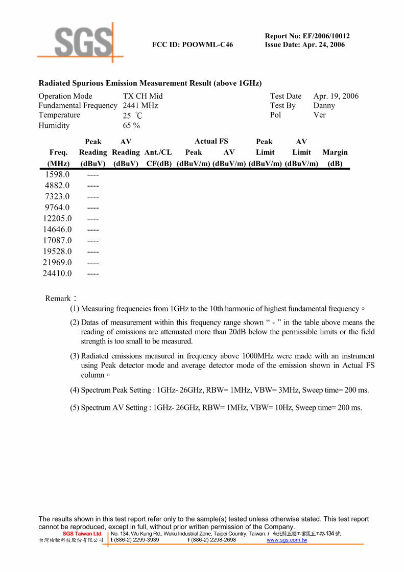
Radiated Spurious Emission Measurement Result (above 1GHz) Operation Mode TX CH Mid Test Date Apr. 19, 2006 Fundamental Frequency 2441 MHz Test By Danny Temperature 25 ℃ Pol Ver Humidity 65 %
Peak AV Peak AVFreq. Reading Reading Ant./CL Peak AV Limit Limit Margin
(MHz) (dBuV) (dBuV) CF(dB) (dBuV/m) (dBuV/m) (dBuV/m) (dBuV/m) (dB)1598.0 ----4882.0 ----7323.0 ----9764.0 ----
12205.0 ----14646.0 ----17087.0 ----19528.0 ----21969.0 ----24410.0 ----
Actual FS
Remark: (1) Measuring frequencies from 1GHz to the 10th harmonic of highest fundamental frequency。
(2) Datas of measurement within this frequency range shown “ - ” in the table above means the reading of emissions are attenuated more than 20dB below the permissible limits or the field strength is too small to be measured.
(3) Radiated emissions measured in frequency above 1000MHz were made with an instrument using Peak detector mode and average detector mode of the emission shown in Actual FScolumn。
(4) Spectrum Peak Setting : 1GHz- 26GHz, RBW= 1MHz, VBW= 3MHz, Sweep time= 200 ms.
(5) Spectrum AV Setting : 1GHz- 26GHz, RBW= 1MHz, VBW= 10Hz, Sweep time= 200 ms.

Report No: EF/2006/10012 FCC ID: POOWML-C46 Issue Date: Apr. 24, 2006
The results shown in this test report refer only to the sample(s) tested unless otherwise stated. This test report cannot be reproduced, except in full, without prior written permission of the Company.
SGS Taiwan Ltd. No. 134, Wu Kung Rd., Wuku Industrial Zone, Taipei Country, Taiwan. / 台北縣五股工業區五工路134號 台灣檢驗科技股份有限公司 t (886-2) 2299-3939 f (886-2) 2298-2698 www.sgs.com.tw
Radiated Spurious Emission Measurement Result (above 1GHz) Operation Mode TX CH Mid Test Date Apr. 19, 2006 Fundamental Frequency 2441 MHz Test By Danny Temperature 25 ℃ Pol Hor Humidity 65 %
Peak AV Peak AVFreq. Reading Reading Ant./CL Peak AV Limit Limit Margin
(MHz) (dBuV) (dBuV) CF(dB) (dBuV/m) (dBuV/m) (dBuV/m) (dBuV/m) (dB)1741.0 41.03 -- -6.19 34.84 -- 74.00 54.00 -19.16 Peak4882.0 ----7323.0 ----9764.0 ----
12205.0 ----14646.0 ----17087.0 ----19528.0 ----21969.0 ----24410.0 ----
Actual FS
Remark: (1) Measuring frequencies from 1GHz to the 10th harmonic of highest fundamental frequency。
(2) Datas of measurement within this frequency range shown “ - ” in the table above means the reading of emissions are attenuated more than 20dB below the permissible limits or the field strength is too small to be measured.
(3) Radiated emissions measured in frequency above 1000MHz were made with an instrument using Peak detector mode and average detector mode of the emission shown in Actual FScolumn。
(4) Spectrum Peak Setting : 1GHz- 26GHz, RBW= 1MHz, VBW= 3MHz, Sweep time= 200 ms.
(5) Spectrum AV Setting : 1GHz- 26GHz, RBW= 1MHz, VBW= 10Hz, Sweep time= 200 ms.

Report No: EF/2006/10012 FCC ID: POOWML-C46 Issue Date: Apr. 24, 2006
The results shown in this test report refer only to the sample(s) tested unless otherwise stated. This test report cannot be reproduced, except in full, without prior written permission of the Company.
SGS Taiwan Ltd. No. 134, Wu Kung Rd., Wuku Industrial Zone, Taipei Country, Taiwan. / 台北縣五股工業區五工路134號 台灣檢驗科技股份有限公司 t (886-2) 2299-3939 f (886-2) 2298-2698 www.sgs.com.tw
Radiated Spurious Emission Measurement Result (above 1GHz) Operation Mode TX CH High Test Date Apr. 19, 2006 Fundamental Frequency 2480 MHz Test By Danny Temperature 25 ℃ Pol Ver. Humidity 65 %
Peak AV Peak AVFreq. Reading Reading Ant./CL Peak AV Limit Limit Margin
(MHz) (dBuV) (dBuV) CF(dB) (dBuV/m) (dBuV/m) (dBuV/m) (dBuV/m) (dB)1598.0 ----4960.0 ----7440.0 ----9920.0 ----
12400.0 ----14880.0 ----17360.0 ----19840.0 ----22320.0 ----24800.0 ----
Actual FS
Remark:
(1) Measuring frequencies from 1GHz to the 10th harmonic of highest fundamental frequency。 (2) Datas of measurement within this frequency range shown “ - ” in the table above means the
reading of emissions are attenuated more than 20dB below the permissible limits or the field strength is too small to be measured.
(3) Radiated emissions measured in frequency above 1000MHz were made with an instrument using Peak detector mode and average detector mode of the emission shown in Actual FScolumn。
(4) Spectrum Peak Setting : 1GHz- 26GHz, RBW= 1MHz, VBW= 3MHz, Sweep time= 200 ms.
(5) Spectrum AV Setting : 1GHz- 26GHz, RBW= 1MHz, VBW= 10Hz, Sweep time= 200 ms.

Report No: EF/2006/10012 FCC ID: POOWML-C46 Issue Date: Apr. 24, 2006
The results shown in this test report refer only to the sample(s) tested unless otherwise stated. This test report cannot be reproduced, except in full, without prior written permission of the Company.
SGS Taiwan Ltd. No. 134, Wu Kung Rd., Wuku Industrial Zone, Taipei Country, Taiwan. / 台北縣五股工業區五工路134號 台灣檢驗科技股份有限公司 t (886-2) 2299-3939 f (886-2) 2298-2698 www.sgs.com.tw
Radiated Spurious Emission Measurement Result (above 1GHz) Operation Mode TX CH High Test Date Apr. 19, 2006 Fundamental Frequency 2480 MHz Test By Danny Temperature 25 ℃ Pol Hor Humidity 65 %
Peak AV Peak AVFreq. Reading Reading Ant./CL Peak AV Limit Limit Margin
(MHz) (dBuV) (dBuV) CF(dB) (dBuV/m) (dBuV/m) (dBuV/m) (dBuV/m) (dB)1598.0 ----4960.0 ----7440.0 ----9920.0 ----
12400.0 ----14880.0 ----17360.0 ----19840.0 ----22320.0 ----24800.0 ----
Actual FS
Remark: (1) Measuring frequencies from 1GHz to the 10th harmonic of highest fundamental frequency。
(2) Datas of measurement within this frequency range shown “ - ” in the table above means the reading of emissions are attenuated more than 20dB below the permissible limits or the field strength is too small to be measured.
(3) Radiated emissions measured in frequency above 1000MHz were made with an instrument using Peak detector mode and average detector mode of the emission shown in Actual FScolumn。
(4) Spectrum Peak Setting : 1GHz- 26GHz, RBW= 1MHz, VBW= 3MHz, Sweep time= 200 ms.
(5) Spectrum AV Setting : 1GHz- 26GHz, RBW= 1MHz, VBW= 10Hz, Sweep time= 200 ms.

Report No: EF/2006/10012 FCC ID: POOWML-C46 Issue Date: Apr. 24, 2006
The results shown in this test report refer only to the sample(s) tested unless otherwise stated. This test report cannot be reproduced, except in full, without prior written permission of the Company.
SGS Taiwan Ltd. No. 134, Wu Kung Rd., Wuku Industrial Zone, Taipei Country, Taiwan. / 台北縣五股工業區五工路134號 台灣檢驗科技股份有限公司 t (886-2) 2299-3939 f (886-2) 2298-2698 www.sgs.com.tw
9. FREQUENCY SEPARATION
10.1. Standard Applicable According to §15.247(a)(1), Frequency hopping systems shall have hopping channel carrier frequencies separated by minimum of 25KHz or the 20dB bandwidth of the hopping channel, whichever is greater.
10.2. Measurement Procedure 1. Place the EUT on the table and set it in transmitting mode. 2. Remove the antenna from the EUT and then connect a low loss RF cable from the antenna port
to the spectrum analyzer. 3. Set center frequency of spectrum analyzer = middle of hopping channel . 4. Set the spectrum analyzer as RBW,VBW=100KHz, Adjust Span to 5 MHz, Sweep = auto. 5. Max hold. Mark 3 Peaks of hopping channel and record the 3 peaks frequency.
10.3. Measurement Result
Channel separation Limit Result
MHz kHz
1 >=25KHz or 2/3*20 dB bandwidth PASS
10.4. Measurement Equipment Used:
Conducted Emission Test Site EQUIPMENT
TYPE MFR MODEL
NUMBERSERIAL
NUMBER LAST CAL.
CAL DUE.
Spectrum Analyzer Agilent E4446A MY43360126 03/29/2006 03/28/2007Spectrum Analyzer Agilent 7405A US41160416 06/28/2005 06/29/2006Spectrum Analyzer R&S FSP 40 100034 11/09/2005 11/10/2006
Low Loss Cable HUBER+SUHNER
SUCOFLEX 104PEA N/A N/A N/A
Attenuator Mini-Circult BW-S10W5 N/A 10/07/2005 10/06/2006Attenuator Mini-Circult BW-S6W5 N/A 10/07/2005 10/06/2006
Splitter Mini-Circult ZFSC-2-10G N/A 10/07/2005 10/06/2006

Report No: EF/2006/10012 FCC ID: POOWML-C46 Issue Date: Apr. 24, 2006
The results shown in this test report refer only to the sample(s) tested unless otherwise stated. This test report cannot be reproduced, except in full, without prior written permission of the Company.
SGS Taiwan Ltd. No. 134, Wu Kung Rd., Wuku Industrial Zone, Taipei Country, Taiwan. / 台北縣五股工業區五工路134號 台灣檢驗科技股份有限公司 t (886-2) 2299-3939 f (886-2) 2298-2698 www.sgs.com.tw
Frequency Separation Test Data

Report No: EF/2006/10012 FCC ID: POOWML-C46 Issue Date: Apr. 24, 2006
The results shown in this test report refer only to the sample(s) tested unless otherwise stated. This test report cannot be reproduced, except in full, without prior written permission of the Company.
SGS Taiwan Ltd. No. 134, Wu Kung Rd., Wuku Industrial Zone, Taipei Country, Taiwan. / 台北縣五股工業區五工路134號 台灣檢驗科技股份有限公司 t (886-2) 2299-3939 f (886-2) 2298-2698 www.sgs.com.tw
10. NUMBER OF HOPPING FREQUENCY
11.1. Standard Applicable According to §15.247(a)(1)(iii), Frequency hopping systems operating in the 2400MHz-2483.5 MHz bands shall use at least 15 hopping frequencies.
11.2. Measurement Procedure
1. Place the EUT on the table and set it in transmitting mode. 2. Remove the antenna from the EUT and then connect a low loss RF cable from the antenna port
to the spectrum analyzer. 3. Set spectrum analyzer Start=2400MHz, Stop = 2483.5MHz, Sweep = auto. 4. Set the spectrum analyzer as RBW,VBW=100KHz, 5. Max hold, view and count how many channel in the band.
11.3. Measurement Result
The nominal channel spacing of the Bluetooth system is 1Mhz independent of the operating mode. The maximum “initial carrier frequency tolerance” which is allowed for Bluetooth is fcenter = 75 kHz. This was checked during the Bluetooth Qualification tests (Test Case: TRM/CA/07-E) for three fre-quencies (2402, 2441, 2480 MHz). Additionally an example for the channel separation is given in the test report
Limit(CH)
Measurement result(CH) Result
15 79 Pass
Total No ofhopping channel

Report No: EF/2006/10012 FCC ID: POOWML-C46 Issue Date: Apr. 24, 2006
The results shown in this test report refer only to the sample(s) tested unless otherwise stated. This test report cannot be reproduced, except in full, without prior written permission of the Company.
SGS Taiwan Ltd. No. 134, Wu Kung Rd., Wuku Industrial Zone, Taipei Country, Taiwan. / 台北縣五股工業區五工路134號 台灣檢驗科技股份有限公司 t (886-2) 2299-3939 f (886-2) 2298-2698 www.sgs.com.tw
11.4. Measurement Equipment Used:
Conducted Emission Test Site EQUIPMENT
TYPE MFR MODEL
NUMBERSERIAL
NUMBER LAST CAL.
CAL DUE.
Spectrum Analyzer Agilent E4446A MY43360126 03/29/2006 03/28/2007Spectrum Analyzer Agilent 7405A US41160416 06/28/2005 06/29/2006Spectrum Analyzer R&S FSP 40 100034 11/09/2005 11/10/2006
Low Loss Cable HUBER+SUHNER SUCOFLEX 104PEA N/A N/A N/A
Attenuator Mini-Circult BW-S10W5 N/A 10/07/2005 10/06/2006Attenuator Mini-Circult BW-S6W5 N/A 10/07/2005 10/06/2006
Splitter Mini-Circult ZFSC-2-10G N/A 10/07/2005 10/06/2006

Report No: EF/2006/10012 FCC ID: POOWML-C46 Issue Date: Apr. 24, 2006
The results shown in this test report refer only to the sample(s) tested unless otherwise stated. This test report cannot be reproduced, except in full, without prior written permission of the Company.
SGS Taiwan Ltd. No. 134, Wu Kung Rd., Wuku Industrial Zone, Taipei Country, Taiwan. / 台北縣五股工業區五工路134號 台灣檢驗科技股份有限公司 t (886-2) 2299-3939 f (886-2) 2298-2698 www.sgs.com.tw
Channel Number 2.4 GHz – 2.441GHz
2.441 GHz – 2.4835GHz
Report No: EF/2006/10012 FCC ID: POOWML-C46 Issue Date: Apr. 24, 2006
The results shown in this test report refer only to the sample(s) tested unless otherwise stated. This test report cannot be reproduced, except in full, without prior written permission of the Company.
SGS Taiwan Ltd. No. 134, Wu Kung Rd., Wuku Industrial Zone, Taipei Country, Taiwan. / 台北縣五股工業區五工路134號 台灣檢驗科技股份有限公司 t (886-2) 2299-3939 f (886-2) 2298-2698 www.sgs.com.tw
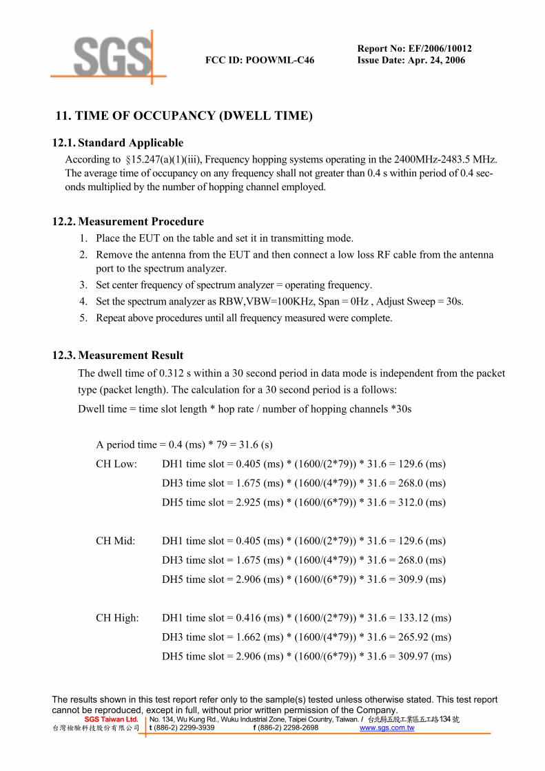
11. TIME OF OCCUPANCY (DWELL TIME)
12.1. Standard Applicable According to §15.247(a)(1)(iii), Frequency hopping systems operating in the 2400MHz-2483.5 MHz. The average time of occupancy on any frequency shall not greater than 0.4 s within period of 0.4 sec-onds multiplied by the number of hopping channel employed.
12.2. Measurement Procedure 1. Place the EUT on the table and set it in transmitting mode. 2. Remove the antenna from the EUT and then connect a low loss RF cable from the antenna
port to the spectrum analyzer. 3. Set center frequency of spectrum analyzer = operating frequency. 4. Set the spectrum analyzer as RBW,VBW=100KHz, Span = 0Hz , Adjust Sweep = 30s. 5. Repeat above procedures until all frequency measured were complete.
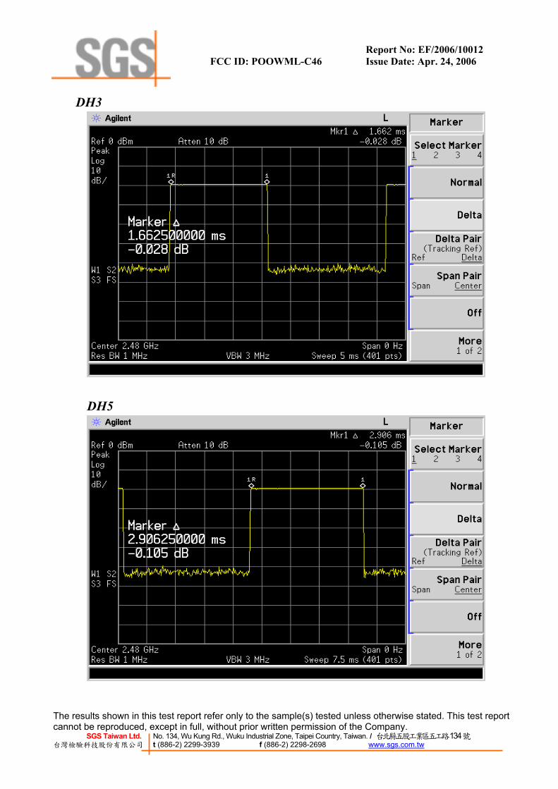
12.3. Measurement Result The dwell time of 0.312 s within a 30 second period in data mode is independent from the packet type (packet length). The calculation for a 30 second period is a follows:
Dwell time = time slot length * hop rate / number of hopping channels *30s
A period time = 0.4 (ms) * 79 = 31.6 (s)
CH Low: DH1 time slot = 0.405 (ms) * (1600/(2*79)) * 31.6 = 129.6 (ms)
DH3 time slot = 1.675 (ms) * (1600/(4*79)) * 31.6 = 268.0 (ms)
DH5 time slot = 2.925 (ms) * (1600/(6*79)) * 31.6 = 312.0 (ms)
CH Mid: DH1 time slot = 0.405 (ms) * (1600/(2*79)) * 31.6 = 129.6 (ms)
DH3 time slot = 1.675 (ms) * (1600/(4*79)) * 31.6 = 268.0 (ms)
DH5 time slot = 2.906 (ms) * (1600/(6*79)) * 31.6 = 309.9 (ms)
CH High: DH1 time slot = 0.416 (ms) * (1600/(2*79)) * 31.6 = 133.12 (ms)
DH3 time slot = 1.662 (ms) * (1600/(4*79)) * 31.6 = 265.92 (ms)
DH5 time slot = 2.906 (ms) * (1600/(6*79)) * 31.6 = 309.97 (ms)
Report No: EF/2006/10012 FCC ID: POOWML-C46 Issue Date: Apr. 24, 2006
The results shown in this test report refer only to the sample(s) tested unless otherwise stated. This test report cannot be reproduced, except in full, without prior written permission of the Company.
SGS Taiwan Ltd. No. 134, Wu Kung Rd., Wuku Industrial Zone, Taipei Country, Taiwan. / 台北縣五股工業區五工路134號 台灣檢驗科技股份有限公司 t (886-2) 2299-3939 f (886-2) 2298-2698 www.sgs.com.tw
12.4. Measurement Equipment Used:
Conducted Emission Test Site EQUIPMENT
TYPE MFR MODEL
NUMBERSERIAL
NUMBER LAST CAL.
CAL DUE.
Spectrum Analyzer Agilent E4446A MY43360126 03/29/2006 03/28/2007Spectrum Analyzer Agilent 7405A US41160416 06/28/2005 06/29/2006Spectrum Analyzer R&S FSP 40 100034 11/09/2005 11/10/2006
Low Loss Cable HUBER+SUHNER
SUCOFLEX 104PEA N/A N/A N/A
Attenuator Mini-Circult BW-S10W5 N/A 10/07/2005 10/06/2006Attenuator Mini-Circult BW-S6W5 N/A 10/07/2005 10/06/2006
Splitter Mini-Circult ZFSC-2-10G N/A 10/07/2005 10/06/2006

Report No: EF/2006/10012 FCC ID: POOWML-C46 Issue Date: Apr. 24, 2006
The results shown in this test report refer only to the sample(s) tested unless otherwise stated. This test report cannot be reproduced, except in full, without prior written permission of the Company.
SGS Taiwan Ltd. No. 134, Wu Kung Rd., Wuku Industrial Zone, Taipei Country, Taiwan. / 台北縣五股工業區五工路134號 台灣檢驗科技股份有限公司 t (886-2) 2299-3939 f (886-2) 2298-2698 www.sgs.com.tw
Dwell Time Test Data CH-Low
DH1

Report No: EF/2006/10012 FCC ID: POOWML-C46 Issue Date: Apr. 24, 2006
The results shown in this test report refer only to the sample(s) tested unless otherwise stated. This test report cannot be reproduced, except in full, without prior written permission of the Company.
SGS Taiwan Ltd. No. 134, Wu Kung Rd., Wuku Industrial Zone, Taipei Country, Taiwan. / 台北縣五股工業區五工路134號 台灣檢驗科技股份有限公司 t (886-2) 2299-3939 f (886-2) 2298-2698 www.sgs.com.tw
DH3
DH5

Report No: EF/2006/10012 FCC ID: POOWML-C46 Issue Date: Apr. 24, 2006
The results shown in this test report refer only to the sample(s) tested unless otherwise stated. This test report cannot be reproduced, except in full, without prior written permission of the Company.
SGS Taiwan Ltd. No. 134, Wu Kung Rd., Wuku Industrial Zone, Taipei Country, Taiwan. / 台北縣五股工業區五工路134號 台灣檢驗科技股份有限公司 t (886-2) 2299-3939 f (886-2) 2298-2698 www.sgs.com.tw
CH-Mid DH1
DH3

Report No: EF/2006/10012 FCC ID: POOWML-C46 Issue Date: Apr. 24, 2006
The results shown in this test report refer only to the sample(s) tested unless otherwise stated. This test report cannot be reproduced, except in full, without prior written permission of the Company.
SGS Taiwan Ltd. No. 134, Wu Kung Rd., Wuku Industrial Zone, Taipei Country, Taiwan. / 台北縣五股工業區五工路134號 台灣檢驗科技股份有限公司 t (886-2) 2299-3939 f (886-2) 2298-2698 www.sgs.com.tw
DH5
CH-High
DH1
Report No: EF/2006/10012 FCC ID: POOWML-C46 Issue Date: Apr. 24, 2006
The results shown in this test report refer only to the sample(s) tested unless otherwise stated. This test report cannot be reproduced, except in full, without prior written permission of the Company.
SGS Taiwan Ltd. No. 134, Wu Kung Rd., Wuku Industrial Zone, Taipei Country, Taiwan. / 台北縣五股工業區五工路134號 台灣檢驗科技股份有限公司 t (886-2) 2299-3939 f (886-2) 2298-2698 www.sgs.com.tw
DH3
DH5
Report No: EF/2006/10012 FCC ID: POOWML-C46 Issue Date: Apr. 24, 2006
The results shown in this test report refer only to the sample(s) tested unless otherwise stated. This test report cannot be reproduced, except in full, without prior written permission of the Company.
SGS Taiwan Ltd. No. 134, Wu Kung Rd., Wuku Industrial Zone, Taipei Country, Taiwan. / 台北縣五股工業區五工路134號 台灣檢驗科技股份有限公司 t (886-2) 2299-3939 f (886-2) 2298-2698 www.sgs.com.tw
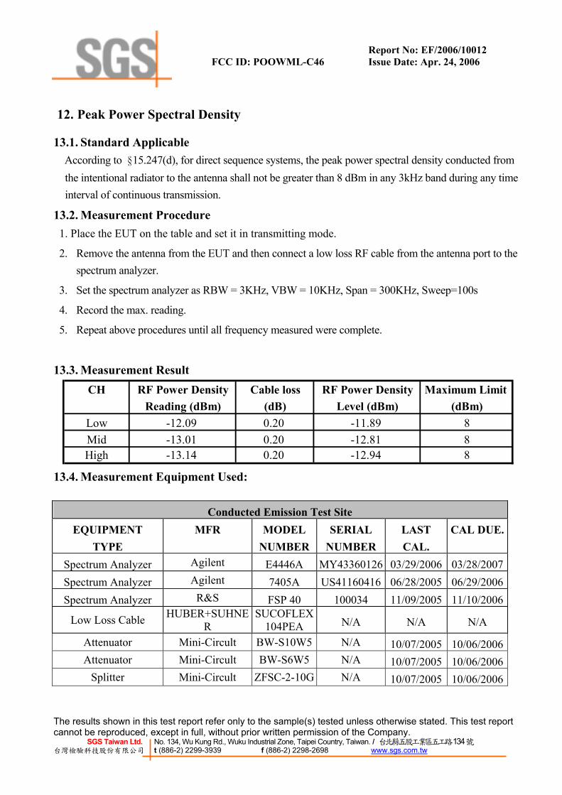
12. Peak Power Spectral Density
13.1. Standard Applicable According to §15.247(d), for direct sequence systems, the peak power spectral density conducted from
the intentional radiator to the antenna shall not be greater than 8 dBm in any 3kHz band during any time interval of continuous transmission.
13.2. Measurement Procedure 1. Place the EUT on the table and set it in transmitting mode.
2. Remove the antenna from the EUT and then connect a low loss RF cable from the antenna port to the spectrum analyzer.
3. Set the spectrum analyzer as RBW = 3KHz, VBW = 10KHz, Span = 300KHz, Sweep=100s
4. Record the max. reading.
5. Repeat above procedures until all frequency measured were complete.
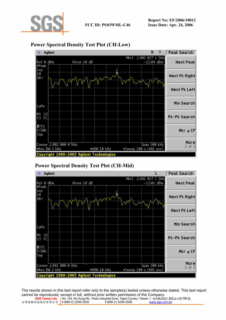
13.3. Measurement Result CH RF Power Density Cable loss RF Power Density Maximum Limit
Reading (dBm) (dB) Level (dBm) (dBm)Low -12.09 0.20 -11.89 8Mid -13.01 0.20 -12.81 8High -13.14 0.20 -12.94 8
13.4. Measurement Equipment Used:
Conducted Emission Test Site EQUIPMENT
TYPE MFR MODEL
NUMBERSERIAL
NUMBER LAST CAL.
CAL DUE.
Spectrum Analyzer Agilent E4446A MY43360126 03/29/2006 03/28/2007Spectrum Analyzer Agilent 7405A US41160416 06/28/2005 06/29/2006Spectrum Analyzer R&S FSP 40 100034 11/09/2005 11/10/2006
Low Loss Cable HUBER+SUHNER
SUCOFLEX 104PEA N/A N/A N/A
Attenuator Mini-Circult BW-S10W5 N/A 10/07/2005 10/06/2006Attenuator Mini-Circult BW-S6W5 N/A 10/07/2005 10/06/2006
Splitter Mini-Circult ZFSC-2-10G N/A 10/07/2005 10/06/2006
Report No: EF/2006/10012 FCC ID: POOWML-C46 Issue Date: Apr. 24, 2006
The results shown in this test report refer only to the sample(s) tested unless otherwise stated. This test report cannot be reproduced, except in full, without prior written permission of the Company.
SGS Taiwan Ltd. No. 134, Wu Kung Rd., Wuku Industrial Zone, Taipei Country, Taiwan. / 台北縣五股工業區五工路134號 台灣檢驗科技股份有限公司 t (886-2) 2299-3939 f (886-2) 2298-2698 www.sgs.com.tw
Power Spectral Density Test Plot (CH-Low)
Power Spectral Density Test Plot (CH-Mid)

Report No: EF/2006/10012 FCC ID: POOWML-C46 Issue Date: Apr. 24, 2006
The results shown in this test report refer only to the sample(s) tested unless otherwise stated. This test report cannot be reproduced, except in full, without prior written permission of the Company.
SGS Taiwan Ltd. No. 134, Wu Kung Rd., Wuku Industrial Zone, Taipei Country, Taiwan. / 台北縣五股工業區五工路134號 台灣檢驗科技股份有限公司 t (886-2) 2299-3939 f (886-2) 2298-2698 www.sgs.com.tw
Power Spectral Density Test Plot (CH-High)

Report No: EF/2006/10012 FCC ID: POOWML-C46 Issue Date: Apr. 24, 2006
The results shown in this test report refer only to the sample(s) tested unless otherwise stated. This test report cannot be reproduced, except in full, without prior written permission of the Company.
SGS Taiwan Ltd. No. 134, Wu Kung Rd., Wuku Industrial Zone, Taipei Country, Taiwan. / 台北縣五股工業區五工路134號 台灣檢驗科技股份有限公司 t (886-2) 2299-3939 f (886-2) 2298-2698 www.sgs.com.tw
13. ANTENNA REQUIREMENT
14.1. Standard Applicable For intentional device, according to §15.203, an intentional radiator shall be designed to ensure that no antenna other than furnished by the responsible party shall be used with the device.
And according to §15.247(4)(1), system operating in the 2400-2483.5MHz bands that are used exclu-sively for fixed, point-to-point operations may employ transmitting antennas with directional gain greater than 6dBi provided the maximum peak output power of the intentional radiator is reduced by 1 dB for every 3 dB that the directional gain of the antenna exceeds 6 dBi.
14.2. Antenna Connected Construction The directional gains of antenna used for transmitting is 2 dBi, and the antenna connector is de-signed with permanent attachment and no consideration of replacement. Please see EUT photo for details.