Embed Size (px)
Citation preview
Journal of Physics Conference Series
OPEN ACCESS
Electromagnetic Vibration Energy Harvester UsingSpringless Proof Mass and Ferrofluid as aLubricantTo cite this article S H Chae et al 2013 J Phys Conf Ser 476 012013
View the article online for updates and enhancements
You may also likeBuilt-in Nonlinear Characteristics of LowPower Operating One-Resistor Selector-Less RRAM By Stacking EngineeringYing-Chen Chen Yao-Feng Chang Chih-Yang Lin et al
-
FinFET Devices and IntegrationHuiming Bu
-
Fracture of Porous Ceramics Applicationto the Mechanical Degradation of SolidOxide Cell During Redox CyclingAmira Abaza Sylvain Meille Arata Nakajoet al
-
This content was downloaded from IP address 13894116181 on 19022022 at 0459
Electromagnetic Vibration Energy Harvester Using Springless Proof Mass and Ferrofluid as a Lubricant
S H Chae1 S Ju1 Y Choi1 S Jun1 S M Park1 S Lee1 H W Lee2 and C-H Ji1 1Department of Electronics Engineering Ewha Womans University Seoul Korea 2Department of Neurology Ewha Womans University School of Medicine Seoul Korea
E-mailcjiewhaackr
Abstract This paper presents an electromagnetic energy harvester using an array of rectangular permanent magnets as springless proof mass and ferrofluid as a lubricating material Lateral motion of the multi-pole magnet array generates voltage across an array of copper windings formed under the aluminum channel in response to low frequency external vibrations such as human-body-induced motion A proof-of-concept device has been fabricated and output voltage has been measured at various input frequencies and accelerations provided by a vibration exciter Device with ferrofluid lubrication generated maximum open-circuit voltage of 047V at 3g vibration at 12Hz which is 8 higher than that of the device without lubricant Maximum output power of 7126μW has been obtained at 408Ω with the device with ferrofluid lubrication
1 Introduction In a variety of areas including wireless sensor nodes and medical implements energy harvesting has attracted research interest as an alternative to conventional internal energy sources which are primary batteries in general Harvesting energy from vibration is drawing notable attention due to rather straightforward power generation mechanism and availability of vibration sources in the environment
Electromagnetic induction based rotary power generators have been widely used and researched in macro and miniature scale applications up to the present [1] Due to the complexity of these systems and difficulties related with translation of motion and providing support for the moving part utilization of spring-supported linear motion has prevailed in most of the electromagnetic energy harvesters [2] In general harvesters based on spring-mass-damper systems require relatively high frequency especially in miniature devices and frequency matching which limit the operation frequency band Alternative techniques are required to harvest energy from low frequency vibrations such as human-body-induced motion To overcome the issues of conventional spring-mass-damper-based devices wide variety of harvesters using springless proof mass have been researched [3-5]
To realize an electromagnetic harvester with springless proof mass means to provide stable relative motion between the permanent magnet and windings while maintaining a narrow gap and magnetization direction are crucial Rolling magnets can be utilized at the expense of rather random variation of magnetization direction [5] Ball bearing has proven to be effective in some applications but the wear issue has to be taken into account [6] Utilization of cylindrical magnet has also been demonstrated [4] In this research we have utilized ferrofluid as a lubricant for a multi-pole rectangular magnet assembly which undergoes a linear sliding motion Ferrofluid is a colloidal suspension containing ferromagnetic nanoparticles with friction-reducing capabilities on a magnet
PowerMEMS 2013 IOP PublishingJournal of Physics Conference Series 476 (2013) 012013 doi1010881742-65964761012013
Content from this work may be used under the terms of the Creative Commons Attribution 30 licence Any further distributionof this work must maintain attribution to the author(s) and the title of the work journal citation and DOI
Published under licence by IOP Publishing Ltd 1
surface A proof-of-concept electromagnetic vibration energy harvester with springless sliding magnet assembly and ferrofluid as a lubricant has been fabricated and tested
2 Harvester design A schematic diagram of the proposed energy harvester is shown in figure 1 Proof-of-concept harvester design utilizes the sliding motion of four NdFeB bar magnets covered with a pure iron plate oscillating in aluminum housing When an external lateral vibration is applied to the device multi-pole magnets oscillate horizontally and voltage is induced across an array of copper windings connected in series Pure iron plate covering the top side of the magnets enhances the magnetic flux across the windings Ferrofluid reduces the friction between the magnet surface and aluminum housing A set of five coils is formed by winding a 01mm-diameter copper wire around the bobbins attached to the bottom of the housing Coil pitch and height of coil are 307mm and 21mm respectively Gap between the magnet assembly and coil is 02mm
Figure 1 Schematic of the proposed energy harvester using springless multi-pole planar magnets with ferrofluid lubrication
3 Fabrication Figure 2 shows the fabricated electromagnetic energy harvester Copper windings are formed with 01mm-diameter copper wire and bobbins machined with acrylic plate Number of turns for each winding is 50 An array of four NdFeB bar magnets which measure 127x318x159mm3 each are attached and covered with a pure iron plate (127x127x02mm3) Aluminum housing has been fabricated by precision CNC (computer numerical control) milling process Channel width and length are 147mm and 1905mm respectively Assembled device which measures 2305x187x45mm3 has been covered with an acrylic plate and tested with and without the ferrofluid Figure 3 shows the array of magnets without pure iron plate before and after and ferrofluid application As shown in figure 3(b) dispensed droplet of ferrofluid tends to gather around the points of higher magnetic flux density When the magnet is flipped and placed inside the housing squeezed ferrofluid droplet forms a thin layer between the magnets and aluminum housing which enables the magnet assembly to smoothly glide on the aluminum surface
(a) (b)
Figure 2 Proof-of-concept energy harvester after assembly (a) bottom side (b) top side
PowerMEMS 2013 IOP PublishingJournal of Physics Conference Series 476 (2013) 012013 doi1010881742-65964761012013
2
(a) (b)
Figure 3 Magnet array (a) in pristine condition (b) after ferrofluid dispense
4 Results and discussion Assembled energy harvester has been tested with a vibration exciter which provides various input frequencies and accelerations Figure 4 shows the experimental setup for the vibration exciter test Sinusoidal vibration has been applied laterally to the harvester with frequency ranging from 7Hz to 20Hz with 1Hz step Acceleration has been varied from 05g to 3g with 05g step at each frequency Because of the limitation of the vibration exciter frequencies under 7Hz and the accelerations above 3g could not be tested
Figure 4 Experimental setup for the vibration exciter test
Open-circuit voltages of the device with and without ferrofluid has been measured and compared at
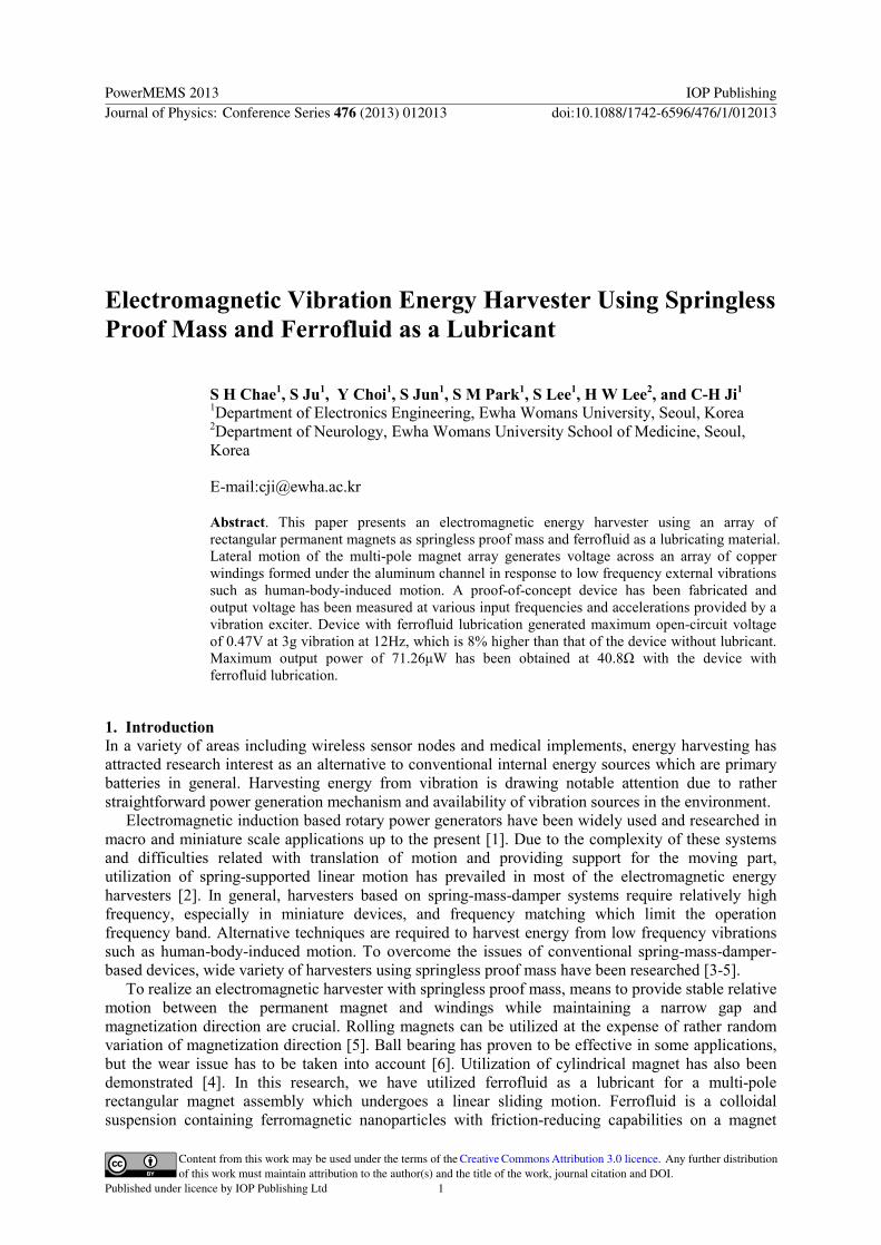
various input frequencies and accelerations (figure 5) Both devices showed relative flat frequency response with clear increasing trend as input acceleration was increased Also output voltage decrease at higher frequency range was observed from both devices At 3g vibration maximum open-circuit voltages of 047V at 12Hz and 044V at 13Hz have been obtained with devices with and without ferrofluid respectively As shown in figure 6 application of ferrofluid increases the open-circuit voltage of the device throughout entire frequency and acceleration ranges
(a) (b)
Figure 5 Peak-to-peak open-circuit voltage at various input frequencies and accelerations (a) device without ferrofluid (b) device with ferrofluid
PowerMEMS 2013 IOP PublishingJournal of Physics Conference Series 476 (2013) 012013 doi1010881742-65964761012013
3
Figure 6 Comparison of the open-circuit voltage with and without ferrofluid
Figure 7 shows the typical open-circuit voltage waveforms of the fabricated devices Due to
reduced friction between magnet assembly and underlying aluminum surface travel range of the magnet per cycle has been increased due to ferrofluid lubrication Moreover velocity of the magnet has been improved which can be evidenced by higher output voltage amplitude Increase in velocity was large enough to overcome the enlarged gap between the magnet and coil as a result of magnet flotation on ferrofluid
(a) (b)
Figure 7 Typical open-circuit voltage waveform (a) device without ferrofluid (3g acceleration at 13Hz) (b) device with ferrofluid (3g acceleration at 12Hz) Output power and root-mean-square output voltage has been obtained at load resistances ranging
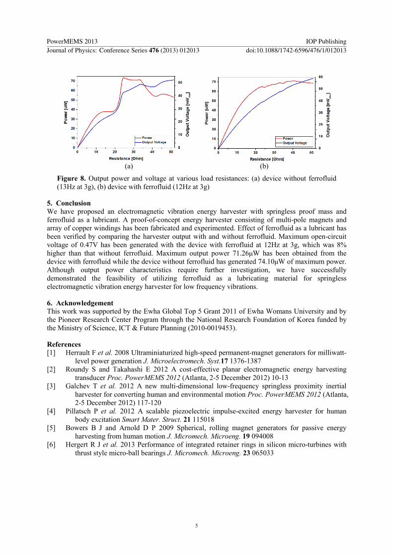
from 116Ω to 515Ω for both devices (figure 8) Input frequencies and accelerations for maximum open-circuit voltages have been used in the experiment Maximum output power of 7126μW has been obtained at 408Ω using the device with ferrofluid For the device without ferrofluid however maximum output power of 7410μW has been achieved at 246Ω Output power of the device without ferrofluid was higher than the device with ferrofluid in 236-335Ω range which require further investigation
Although still a lot of room for performance improvement exists the concept of utilizing ferrofluid as a lubricant for springless electromagnetic vibration energy harvester has been tested successfully In addition to the improvement in output characteristics of the harvesting device ferrofluid lubrication is expected to protect the device from wear and provide enhanced long term reliability For further improvement of the overall device performance geometries of the channel and magnet assembly need to be optimized to reduce the planar rotation of the magnet A thorough quantitative analysis of dispensed ferrofluid volume on magnet flotation and modification of the contact regions to hydrophobic surfaces could further improve the output
PowerMEMS 2013 IOP PublishingJournal of Physics Conference Series 476 (2013) 012013 doi1010881742-65964761012013
4
(a) (b)
Figure 8 Output power and voltage at various load resistances (a) device without ferrofluid (13Hz at 3g) (b) device with ferrofluid (12Hz at 3g)
5 Conclusion We have proposed an electromagnetic vibration energy harvester with springless proof mass and ferrofluid as a lubricant A proof-of-concept energy harvester consisting of multi-pole magnets and array of copper windings has been fabricated and experimented Effect of ferrofluid as a lubricant has been verified by comparing the harvester output with and without ferrofluid Maximum open-circuit voltage of 047V has been generated with the device with ferrofluid at 12Hz at 3g which was 8 higher than that without ferrofluid Maximum output power 7126μW has been obtained from the device with ferrofluid while the device without ferrofluid has generated 7410μW of maximum power Although output power characteristics require further investigation we have successfully demonstrated the feasibility of utilizing ferrofluid as a lubricating material for springless electromagnetic vibration energy harvester for low frequency vibrations
6 Acknowledgement This work was supported by the Ewha Global Top 5 Grant 2011 of Ewha Womans University and by the Pioneer Research Center Program through the National Research Foundation of Korea funded by the Ministry of Science ICT amp Future Planning (2010-0019453)
References [1] Herrault F et al 2008 Ultraminiaturized high-speed permanent-magnet generators for milliwatt-
level power generation J Microelectromech Syst17 1376-1387 [2] Roundy S and Takahashi E 2012 A cost-effective planar electromagnetic energy harvesting
transducer Proc PowerMEMS 2012 (Atlanta 2-5 December 2012) 10-13 [3] Galchev T et al 2012 A new multi-dimensional low-frequency springless proximity inertial
harvester for converting human and environmental motion Proc PowerMEMS 2012 (Atlanta 2-5 December 2012) 117-120
[4] Pillatsch P et al 2012 A scalable piezoelectric impulse-excited energy harvester for human body excitation Smart Mater Struct 21 115018
[5] Bowers B J and Arnold D P 2009 Spherical rolling magnet generators for passive energy harvesting from human motion J Micromech Microeng 19 094008
[6] Hergert R J et al 2013 Performance of integrated retainer rings in silicon micro-turbines with thrust style micro-ball bearings J Micromech Microeng 23 065033
PowerMEMS 2013 IOP PublishingJournal of Physics Conference Series 476 (2013) 012013 doi1010881742-65964761012013
5
Electromagnetic Vibration Energy Harvester Using Springless Proof Mass and Ferrofluid as a Lubricant
S H Chae1 S Ju1 Y Choi1 S Jun1 S M Park1 S Lee1 H W Lee2 and C-H Ji1 1Department of Electronics Engineering Ewha Womans University Seoul Korea 2Department of Neurology Ewha Womans University School of Medicine Seoul Korea
E-mailcjiewhaackr
Abstract This paper presents an electromagnetic energy harvester using an array of rectangular permanent magnets as springless proof mass and ferrofluid as a lubricating material Lateral motion of the multi-pole magnet array generates voltage across an array of copper windings formed under the aluminum channel in response to low frequency external vibrations such as human-body-induced motion A proof-of-concept device has been fabricated and output voltage has been measured at various input frequencies and accelerations provided by a vibration exciter Device with ferrofluid lubrication generated maximum open-circuit voltage of 047V at 3g vibration at 12Hz which is 8 higher than that of the device without lubricant Maximum output power of 7126μW has been obtained at 408Ω with the device with ferrofluid lubrication
1 Introduction In a variety of areas including wireless sensor nodes and medical implements energy harvesting has attracted research interest as an alternative to conventional internal energy sources which are primary batteries in general Harvesting energy from vibration is drawing notable attention due to rather straightforward power generation mechanism and availability of vibration sources in the environment
Electromagnetic induction based rotary power generators have been widely used and researched in macro and miniature scale applications up to the present [1] Due to the complexity of these systems and difficulties related with translation of motion and providing support for the moving part utilization of spring-supported linear motion has prevailed in most of the electromagnetic energy harvesters [2] In general harvesters based on spring-mass-damper systems require relatively high frequency especially in miniature devices and frequency matching which limit the operation frequency band Alternative techniques are required to harvest energy from low frequency vibrations such as human-body-induced motion To overcome the issues of conventional spring-mass-damper-based devices wide variety of harvesters using springless proof mass have been researched [3-5]
To realize an electromagnetic harvester with springless proof mass means to provide stable relative motion between the permanent magnet and windings while maintaining a narrow gap and magnetization direction are crucial Rolling magnets can be utilized at the expense of rather random variation of magnetization direction [5] Ball bearing has proven to be effective in some applications but the wear issue has to be taken into account [6] Utilization of cylindrical magnet has also been demonstrated [4] In this research we have utilized ferrofluid as a lubricant for a multi-pole rectangular magnet assembly which undergoes a linear sliding motion Ferrofluid is a colloidal suspension containing ferromagnetic nanoparticles with friction-reducing capabilities on a magnet
PowerMEMS 2013 IOP PublishingJournal of Physics Conference Series 476 (2013) 012013 doi1010881742-65964761012013
Content from this work may be used under the terms of the Creative Commons Attribution 30 licence Any further distributionof this work must maintain attribution to the author(s) and the title of the work journal citation and DOI
Published under licence by IOP Publishing Ltd 1
surface A proof-of-concept electromagnetic vibration energy harvester with springless sliding magnet assembly and ferrofluid as a lubricant has been fabricated and tested
2 Harvester design A schematic diagram of the proposed energy harvester is shown in figure 1 Proof-of-concept harvester design utilizes the sliding motion of four NdFeB bar magnets covered with a pure iron plate oscillating in aluminum housing When an external lateral vibration is applied to the device multi-pole magnets oscillate horizontally and voltage is induced across an array of copper windings connected in series Pure iron plate covering the top side of the magnets enhances the magnetic flux across the windings Ferrofluid reduces the friction between the magnet surface and aluminum housing A set of five coils is formed by winding a 01mm-diameter copper wire around the bobbins attached to the bottom of the housing Coil pitch and height of coil are 307mm and 21mm respectively Gap between the magnet assembly and coil is 02mm
Figure 1 Schematic of the proposed energy harvester using springless multi-pole planar magnets with ferrofluid lubrication
3 Fabrication Figure 2 shows the fabricated electromagnetic energy harvester Copper windings are formed with 01mm-diameter copper wire and bobbins machined with acrylic plate Number of turns for each winding is 50 An array of four NdFeB bar magnets which measure 127x318x159mm3 each are attached and covered with a pure iron plate (127x127x02mm3) Aluminum housing has been fabricated by precision CNC (computer numerical control) milling process Channel width and length are 147mm and 1905mm respectively Assembled device which measures 2305x187x45mm3 has been covered with an acrylic plate and tested with and without the ferrofluid Figure 3 shows the array of magnets without pure iron plate before and after and ferrofluid application As shown in figure 3(b) dispensed droplet of ferrofluid tends to gather around the points of higher magnetic flux density When the magnet is flipped and placed inside the housing squeezed ferrofluid droplet forms a thin layer between the magnets and aluminum housing which enables the magnet assembly to smoothly glide on the aluminum surface
(a) (b)
Figure 2 Proof-of-concept energy harvester after assembly (a) bottom side (b) top side
PowerMEMS 2013 IOP PublishingJournal of Physics Conference Series 476 (2013) 012013 doi1010881742-65964761012013
2
(a) (b)
Figure 3 Magnet array (a) in pristine condition (b) after ferrofluid dispense
4 Results and discussion Assembled energy harvester has been tested with a vibration exciter which provides various input frequencies and accelerations Figure 4 shows the experimental setup for the vibration exciter test Sinusoidal vibration has been applied laterally to the harvester with frequency ranging from 7Hz to 20Hz with 1Hz step Acceleration has been varied from 05g to 3g with 05g step at each frequency Because of the limitation of the vibration exciter frequencies under 7Hz and the accelerations above 3g could not be tested
Figure 4 Experimental setup for the vibration exciter test
Open-circuit voltages of the device with and without ferrofluid has been measured and compared at
various input frequencies and accelerations (figure 5) Both devices showed relative flat frequency response with clear increasing trend as input acceleration was increased Also output voltage decrease at higher frequency range was observed from both devices At 3g vibration maximum open-circuit voltages of 047V at 12Hz and 044V at 13Hz have been obtained with devices with and without ferrofluid respectively As shown in figure 6 application of ferrofluid increases the open-circuit voltage of the device throughout entire frequency and acceleration ranges
(a) (b)
Figure 5 Peak-to-peak open-circuit voltage at various input frequencies and accelerations (a) device without ferrofluid (b) device with ferrofluid
PowerMEMS 2013 IOP PublishingJournal of Physics Conference Series 476 (2013) 012013 doi1010881742-65964761012013
3
Figure 6 Comparison of the open-circuit voltage with and without ferrofluid
Figure 7 shows the typical open-circuit voltage waveforms of the fabricated devices Due to
reduced friction between magnet assembly and underlying aluminum surface travel range of the magnet per cycle has been increased due to ferrofluid lubrication Moreover velocity of the magnet has been improved which can be evidenced by higher output voltage amplitude Increase in velocity was large enough to overcome the enlarged gap between the magnet and coil as a result of magnet flotation on ferrofluid
(a) (b)
Figure 7 Typical open-circuit voltage waveform (a) device without ferrofluid (3g acceleration at 13Hz) (b) device with ferrofluid (3g acceleration at 12Hz) Output power and root-mean-square output voltage has been obtained at load resistances ranging
from 116Ω to 515Ω for both devices (figure 8) Input frequencies and accelerations for maximum open-circuit voltages have been used in the experiment Maximum output power of 7126μW has been obtained at 408Ω using the device with ferrofluid For the device without ferrofluid however maximum output power of 7410μW has been achieved at 246Ω Output power of the device without ferrofluid was higher than the device with ferrofluid in 236-335Ω range which require further investigation
Although still a lot of room for performance improvement exists the concept of utilizing ferrofluid as a lubricant for springless electromagnetic vibration energy harvester has been tested successfully In addition to the improvement in output characteristics of the harvesting device ferrofluid lubrication is expected to protect the device from wear and provide enhanced long term reliability For further improvement of the overall device performance geometries of the channel and magnet assembly need to be optimized to reduce the planar rotation of the magnet A thorough quantitative analysis of dispensed ferrofluid volume on magnet flotation and modification of the contact regions to hydrophobic surfaces could further improve the output
PowerMEMS 2013 IOP PublishingJournal of Physics Conference Series 476 (2013) 012013 doi1010881742-65964761012013
4
(a) (b)
Figure 8 Output power and voltage at various load resistances (a) device without ferrofluid (13Hz at 3g) (b) device with ferrofluid (12Hz at 3g)
5 Conclusion We have proposed an electromagnetic vibration energy harvester with springless proof mass and ferrofluid as a lubricant A proof-of-concept energy harvester consisting of multi-pole magnets and array of copper windings has been fabricated and experimented Effect of ferrofluid as a lubricant has been verified by comparing the harvester output with and without ferrofluid Maximum open-circuit voltage of 047V has been generated with the device with ferrofluid at 12Hz at 3g which was 8 higher than that without ferrofluid Maximum output power 7126μW has been obtained from the device with ferrofluid while the device without ferrofluid has generated 7410μW of maximum power Although output power characteristics require further investigation we have successfully demonstrated the feasibility of utilizing ferrofluid as a lubricating material for springless electromagnetic vibration energy harvester for low frequency vibrations
6 Acknowledgement This work was supported by the Ewha Global Top 5 Grant 2011 of Ewha Womans University and by the Pioneer Research Center Program through the National Research Foundation of Korea funded by the Ministry of Science ICT amp Future Planning (2010-0019453)
References [1] Herrault F et al 2008 Ultraminiaturized high-speed permanent-magnet generators for milliwatt-
level power generation J Microelectromech Syst17 1376-1387 [2] Roundy S and Takahashi E 2012 A cost-effective planar electromagnetic energy harvesting
transducer Proc PowerMEMS 2012 (Atlanta 2-5 December 2012) 10-13 [3] Galchev T et al 2012 A new multi-dimensional low-frequency springless proximity inertial
harvester for converting human and environmental motion Proc PowerMEMS 2012 (Atlanta 2-5 December 2012) 117-120
[4] Pillatsch P et al 2012 A scalable piezoelectric impulse-excited energy harvester for human body excitation Smart Mater Struct 21 115018
[5] Bowers B J and Arnold D P 2009 Spherical rolling magnet generators for passive energy harvesting from human motion J Micromech Microeng 19 094008
[6] Hergert R J et al 2013 Performance of integrated retainer rings in silicon micro-turbines with thrust style micro-ball bearings J Micromech Microeng 23 065033
PowerMEMS 2013 IOP PublishingJournal of Physics Conference Series 476 (2013) 012013 doi1010881742-65964761012013
5

(a) (b)
Figure 3 Magnet array (a) in pristine condition (b) after ferrofluid dispense
4 Results and discussion Assembled energy harvester has been tested with a vibration exciter which provides various input frequencies and accelerations Figure 4 shows the experimental setup for the vibration exciter test Sinusoidal vibration has been applied laterally to the harvester with frequency ranging from 7Hz to 20Hz with 1Hz step Acceleration has been varied from 05g to 3g with 05g step at each frequency Because of the limitation of the vibration exciter frequencies under 7Hz and the accelerations above 3g could not be tested
Figure 4 Experimental setup for the vibration exciter test
Open-circuit voltages of the device with and without ferrofluid has been measured and compared at
various input frequencies and accelerations (figure 5) Both devices showed relative flat frequency response with clear increasing trend as input acceleration was increased Also output voltage decrease at higher frequency range was observed from both devices At 3g vibration maximum open-circuit voltages of 047V at 12Hz and 044V at 13Hz have been obtained with devices with and without ferrofluid respectively As shown in figure 6 application of ferrofluid increases the open-circuit voltage of the device throughout entire frequency and acceleration ranges
(a) (b)
Figure 5 Peak-to-peak open-circuit voltage at various input frequencies and accelerations (a) device without ferrofluid (b) device with ferrofluid
PowerMEMS 2013 IOP PublishingJournal of Physics Conference Series 476 (2013) 012013 doi1010881742-65964761012013
3
Figure 6 Comparison of the open-circuit voltage with and without ferrofluid
Figure 7 shows the typical open-circuit voltage waveforms of the fabricated devices Due to
reduced friction between magnet assembly and underlying aluminum surface travel range of the magnet per cycle has been increased due to ferrofluid lubrication Moreover velocity of the magnet has been improved which can be evidenced by higher output voltage amplitude Increase in velocity was large enough to overcome the enlarged gap between the magnet and coil as a result of magnet flotation on ferrofluid
(a) (b)
Figure 7 Typical open-circuit voltage waveform (a) device without ferrofluid (3g acceleration at 13Hz) (b) device with ferrofluid (3g acceleration at 12Hz) Output power and root-mean-square output voltage has been obtained at load resistances ranging
from 116Ω to 515Ω for both devices (figure 8) Input frequencies and accelerations for maximum open-circuit voltages have been used in the experiment Maximum output power of 7126μW has been obtained at 408Ω using the device with ferrofluid For the device without ferrofluid however maximum output power of 7410μW has been achieved at 246Ω Output power of the device without ferrofluid was higher than the device with ferrofluid in 236-335Ω range which require further investigation
Although still a lot of room for performance improvement exists the concept of utilizing ferrofluid as a lubricant for springless electromagnetic vibration energy harvester has been tested successfully In addition to the improvement in output characteristics of the harvesting device ferrofluid lubrication is expected to protect the device from wear and provide enhanced long term reliability For further improvement of the overall device performance geometries of the channel and magnet assembly need to be optimized to reduce the planar rotation of the magnet A thorough quantitative analysis of dispensed ferrofluid volume on magnet flotation and modification of the contact regions to hydrophobic surfaces could further improve the output
PowerMEMS 2013 IOP PublishingJournal of Physics Conference Series 476 (2013) 012013 doi1010881742-65964761012013
4
(a) (b)
Figure 8 Output power and voltage at various load resistances (a) device without ferrofluid (13Hz at 3g) (b) device with ferrofluid (12Hz at 3g)
5 Conclusion We have proposed an electromagnetic vibration energy harvester with springless proof mass and ferrofluid as a lubricant A proof-of-concept energy harvester consisting of multi-pole magnets and array of copper windings has been fabricated and experimented Effect of ferrofluid as a lubricant has been verified by comparing the harvester output with and without ferrofluid Maximum open-circuit voltage of 047V has been generated with the device with ferrofluid at 12Hz at 3g which was 8 higher than that without ferrofluid Maximum output power 7126μW has been obtained from the device with ferrofluid while the device without ferrofluid has generated 7410μW of maximum power Although output power characteristics require further investigation we have successfully demonstrated the feasibility of utilizing ferrofluid as a lubricating material for springless electromagnetic vibration energy harvester for low frequency vibrations
6 Acknowledgement This work was supported by the Ewha Global Top 5 Grant 2011 of Ewha Womans University and by the Pioneer Research Center Program through the National Research Foundation of Korea funded by the Ministry of Science ICT amp Future Planning (2010-0019453)
References [1] Herrault F et al 2008 Ultraminiaturized high-speed permanent-magnet generators for milliwatt-
level power generation J Microelectromech Syst17 1376-1387 [2] Roundy S and Takahashi E 2012 A cost-effective planar electromagnetic energy harvesting
transducer Proc PowerMEMS 2012 (Atlanta 2-5 December 2012) 10-13 [3] Galchev T et al 2012 A new multi-dimensional low-frequency springless proximity inertial
harvester for converting human and environmental motion Proc PowerMEMS 2012 (Atlanta 2-5 December 2012) 117-120
[4] Pillatsch P et al 2012 A scalable piezoelectric impulse-excited energy harvester for human body excitation Smart Mater Struct 21 115018
[5] Bowers B J and Arnold D P 2009 Spherical rolling magnet generators for passive energy harvesting from human motion J Micromech Microeng 19 094008
[6] Hergert R J et al 2013 Performance of integrated retainer rings in silicon micro-turbines with thrust style micro-ball bearings J Micromech Microeng 23 065033
PowerMEMS 2013 IOP PublishingJournal of Physics Conference Series 476 (2013) 012013 doi1010881742-65964761012013
5
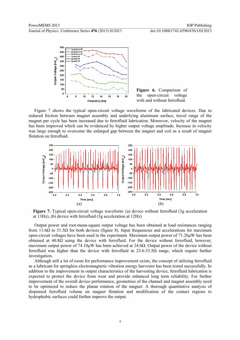