Embed Size (px)
Citation preview

Electron Ballistics
Electronics includes in a broad sense all electrical phenomena , for allelectric conduction involves electrons . The common interpretation ofthe term at present , however , is expressed by a standard definition ! ofelectronics , which is " that field of science and engineering which dealswith electron devices and their utilization ." Here an electron device !
is " a device in which conduction by electrons takes place through avacuum , gas , or semi -conductor ." Electronics has become increasinglyimportant because of its growing application to the problems ofthe electrical industry . During the early years of the industry ,electronic conduction - except for the arc lamp - usually took theform of annoying and somewhat puzzling accidents , such as punctureof insulation , flashover of insulators ) and corona leakage current .Recently , however , despite the fact that electronic conduction still hasmany puzzling aspects , scientists and engineers have found an increasing
number of ways in which it can be harnessed , guided , and
control led for useful purposes . Electronics consequently is now asimportant to the engineer concerned with rolling of steel rails or thepropulsion of battleships as to the engineer concerned with thecommunication of intelligence .
The occurrence of electronic conduction is widespread , and itsnature diverse . Sometimes it is unconfined , as in lightning or somearcs ; at other times confined , as in the electron tube or the neon sign .Sometimes it is visible , as in the arc light ; at other times invisible , asin the vacuum tube . Sometimes the conduction is undesirable and un -
control led , as in the example of lightning striking a transmission line ,or in corona formation on the line . At other times the conduction is
intentional , and may be control led by minute electrical forces , as inthe electron tube .
The field of application of electronic phenomena already covers avery wide range of power . The asymmetric nonlinear property Corn:-mon to many types of electronic conduction finds application not only
. in the radio detector tube , where the power handled is extremelysmall , but also in the rail \vay mercury -arc rectifier that handles thepower to move trains over mountains . The property of certain types ofelectronic conduction that makes possible the control of a large flow,of energy by the expenditure of a relatively small amount of po \ver
1 " Standards on Electron Tubes: Definitions of Terms, 1950," I .R.E. Proc., 38(1950), 433.
1
CHAPTER I

2 ELECTRONBALLISTICS [Ck. I
finds use over ranges of current varying all the way from that in \ Tolved
in the electrometer vacuum tube capable of measuring currents of
10 - 15 ampere to the enormous bursts of current amounting to thousands
of amperes required for modern electric spot - welders and
nuclear particle accelerators .
Electronic conduction through a vacuum or gas takes place by
virtue of the fact that under certain conditions charged particles ,
known as electrons and ions , are liberated from electrodes and produced
in the gas in the conducting path ; and that in the presence of an
impressed electric field these charged particles experience a force
that causes them to move and constitute an electric current . Thus
electronic conduction in a vacuum or gas embraces the following
important physical process es :
( a ) the liberation of charged particles from electrodes ,
( b ) the motion of the particles through the space between the
electrodes ,
( c ) the production of charged particles in the space between the
electrodes , and
( d ) the control of the flow of the particles by the electric field caused
by electrodes interposed in the space , or by the magnetic field
produced by an external means .
Practical circuit elements that embody possible combinations of the
foregoing process es are almost always nonlinear , and effective utili -
zation of such elements in circuits requires an analysis suited to their
nonlinearity .
In the application of electronic devices the engineer must have a
knowledge of their characteristics and limitations . As in most electrical
equipment , the electrical aspects of the design of these devices are
often not the limiting ones ; chemical , thermal , mechanical , and
physical phenomena often govern their rating . A thorough understanding
of the physical principles underlying the behavior of a device
is therefore necessary in order that intelligent application be made of
it . Accordingly , the first part of this book is devoted to a discussion of
the physical aspects of electronic conduction , the second part is a
description of the electrical characteristics of typical electron tubes ,
and the third part is a treatment of the fundamental methods of
circuit analysis and the basic engineering considerations important
in the application of electronic devices .
1. CHARGE AND MASS OF ELEMENTARY PARTICLES
O,,'"era period of years a number of elementary particles of importance in electronic conduction have been identified , and the charge

3CHARGE AND MASS OF PARTICLESArt . 1]
and mass of each have been measured . A few of the more frequentlyencountered particles , all of which are constituents of the atom ,together with their charges and masses, are listed in Table I .
TABLE 1*
l \Tame Charge l11a88
Electron - Q e me
Positron + Qe me
Neutron 0 I ,83sme
Proton + Qe I ,837me
* The symbols e and m are generally used in the literature for the charge and mass ofthe electron; however, in this bool\: the symbol~ shown are used to be consistent \viththose introduced in Electric Circuits.
Note that Qe is the symbol for the magnitude of the charge of an electron- it is apositive number and does not include the negative sign associated with the negativecharge. The negative sign is indicated separately in all the following analytical workwhere Qe appears.
In Table I :
Qe = (1.60203 :f: 0.00034 ) X 10- 19 coulomb } Electronic ~[ 1]
constants inme = (9.1066 :f: 0.0032 ) X 10- 31 kilogram mks units2 ~[2]
Of the elementary particles , the electron is basic in the field of electronics, and the charge and mass of the others are expressed in terms
of its charge and mass . The neutron and the proton are particles whichh.ave the next higher quantity of mass ordinarily observed . Mesons ,which are short -lived charged particles found in cosmic -ray and othernuclear studies , have values of mass intermediate between those of theelectron and the neutron . Neutrinos , which are postulated to satisfythe requirements of nuclear theory , have neither charge nor mass .Neither mesons nor neutrinos have engineering significance at present .The ratio of charge to mass for the electron appears in many of thetheoretical expressions for the motion of charged particles in electric.and magnetic fields ; hence there are numerous ways of measuring itexperimentally . Precise measurements2 give for the ratio the value
Qe/me = (1.7592 :1: 0.0005 ) X 1011 coulombs per kilogram ~[3]
. 2 These values are Tai{en from R. T. Birge, "A New Table of Values of the GeneralPhysical Constants," Rev. Mod. Phys., 13 (October, 1941), Table a, p. 234, and Table c,pp. 236-237, with permission.

Use of nuclear resonance as a measuring tool has resulted in a furtherimprovement3 by a factor of about three in the precision of measurement
of this ratio .
All charged particles of importance in engineering have essentiallymultiples of the charge of the electron or proton . Particles having themass of a molecule and the charge of an electron or proton are knownas positive or negative ions , depending on the sign of their charge .Occasionally particles are encountered which have the mass of themolec ~le and small multiples of the electron 's charge . These are calledmultiple -charged ions . Ions , which are discussed in Ch . III , generallyresult from collision process es in gases.
The v.alue for the mass me given above is for the electron movingwith speeds small compared with the speed of light . This value ofmass is ordinarily called the rest rJ1-ass, although no experimentalmeasurements of mass have yet been made on an electron at rest .Experiment shows that the apparent mass of the electron increaseswith its speed . The theory of relativ :ity ,4 which is based on the hypo -theticallaw that " it is of necessity impossible to determine absolutemotion of bodies by any experiment whatsoever ," predicts that thespeed of light is an asymptotic value unattainable by any materialbody . In other words , the mass of an electron approach es infinity asits speed approach es the speed of light .
The dependence of the mass of any particle on its speed is given bythe expression
3 H. A. Thomas, R. L . Driscoll, and J. A. Hipple, " Determination of elm from Recent. Experiments in Kuclear Resonance," Phys. Rev., 75 (1949), 922.
4 The Encyclopcedia Britannica (14th ed.; New York : Encyclopredia Britannica, Inc.,1938), 89- 99.
* See footnote 2 on page 3.
4 ELECTRON BALLISTICS ECho I
mo,m = VI - (VfC)2 [4]where
meters perx
In general, force is given by the time rate of change of momentum ;that is, .
[5]F=~dt .
m is the mass of the particle in motion ,
mo is the mass of the particle at rest ,
v is the speed of the particle ,
c is the speed of light * - (2.99776 :l : 0.00004 )second .

Phys . Rev ., 30 ( 1927 ),595 - 604 .
* See footnote 2 on page 3 .
Art . 1] CHARGE AND .L~ ASS OF PARTICLES 5
The right -hand side of Eq . 5 reduces to the simple product of mass andacceleration only when the mass is constant . From Eq . 4 it follows thatthe mass is not increased by so much as 1 per cent until the speed ofthe particle reaches about 15 per cent of the speed of light . It is evidentfrom subsequent considerations that this speed is not generallyreached except in devices with impressed voltages that exceed 6,000volts . Hence assumption that the mass is constant at the rest valueis reasonable in computing the force on charged particles in deviceshaving impressed voltages lower than this value .
Because of the electric and magnetic fields surrounding a movingelectron , the mass exhibited in its inertia may be entirely elcctro -magnetic .5 On this assumption , the radius of the equivalent chargedsphere , which has no mass in the ordinary sense, may be calculatedto be about 2 X meter . This is to be compared with the radius ofa molecule , which ranges around meter .6
It is found experimentally that a beam of moving electrons may bediffracted by a metallic crystal in a manner similar to the diffractionof light -waves by a grating .' This wave-like behavior of electronsshows .that the particle concept is not complete . The wavelengthexperimentally found to be associated with a moving electron is
h). = - , [6]
mve
where
h is the Planck radiation constant * - (6.624 :I:: 0.002 ) X 10- 34joule second ,
me is the mass of the electron ,
v is the speed of the electron .
One of the valuable features of electronic devices is the rapidity \vithwhich they act ; it is possible to start , stop , or vary a current \viththem in as short a time as a small fraction of a microsecond . This
rapidity of action results from the extreme agility of the electron -a property associated with the fact that the electron has the largeratio of charge to mass stated in Eq . 3. Although both quantities aresmall , their ratio is very large - much larger than that of any othercharged body dealt with in engineering. The size of this ratio can
5 H . A . Lorentz , The Theory of Electrons (Leipzig : B . G. Teubner , 1909 ).6 R . A . Millikan , Electrons (+ and - ), Protons , Photons , Neutrons , and Cosmic Rays
(2nd ed . ; Chicago : The University of Chicago Press , 1947 ), 184, 188.7 C. Davisson and L . H . Germer , " Diffraction of Electrons by a Crystal of Nickel ,"
705 - 740 ; C. Davisson , " Electron Waves ," J .F .I ., 208 (1929 ),

6 ELECTRO BALLISTICS [Ok. I
perhaps be grasped from a computation of the force of repulsion
between one kilogram of electrons located at each of the poles of the
earth . Their separation is about 7 , 900 miles , or 1 . 27 Xmeters .
Their charge is given by Eq . 3 , and , by Coulomb ' s law , the force of
repulsion between them is
= _. & - ( 1 . 76 x 1011 ) 2
41 Tcvd2 - 41T X 8 . 85 X 10 - 12 X ( 1 . 27 X 107 ) 2 = 1 . 73 X 1018newtons [ 7 ]
= 1 . 95 X 1014 tons. ' [ 8 ]
Clearly , the electron ' s charge - to - mass ratio is enormous to produce
such a large force at such a great distance . Consequently , the electric
force on an electron in an electrostatic field can overcome the inertia
of the electron and produce high velocities in a very short time .
With kno \ v-ledge of the charge and mass of the particles involved in
electronics , it is possible to proceed with the analysis of the motion of
particles in electrostatic and magneto static fields given in the following
articles of this chapter . The source of the charged particles is
reserved for consideration in subsequent chapters . At this point it is
sufficient to know that electrons are given off by a heated metallic
surface , and that electrons and ions are produced in a gas when the
process of ionization occurs .
2 . THE ELEMENTS OF THE OPERATION OF ELECTRON TUBES
An electron tube S is " an electron device in which conduction by
electrons takes place through a vacuum or gaseous medium withiri
a gas - tight envelope . " Ordinarily it consists of two or more metallic
electrodes enclosed in an e \ '"acuated glass or metal chamber . The electrodes
are insulated from one another . If the chamber is evacuated
until the remaining ga .s molecules have no effect - chemically or electrically
- on the operation of the tube , it is called a vaC ~lU111, t ~lbe . Other
tubes contain gas introduced after the evacuation process has been
carried out . These are called gas t ~lbes when the amount of gas is sufficient
to ha \ "e an appreciable effect on their electrical characteristics .
One of the electrodes , called the cathode , serves as a source of electrons
by virtue of one or more of the several electron - emission process es discussed
in Ch . II . Another electrode , called the anode ( or plate ) , is
usually maintained electrically positive with respect to the cathode .
The resulting electric field in the tube exerts ~ force on the electrons
and causes them to mo \ "e toward the anode , thereby setting up an
8 " Standards on Electron Tubes : Definitions of Terms , 1950 ," I .R .E . Proc . , 38
( 1950 ) , 433 .
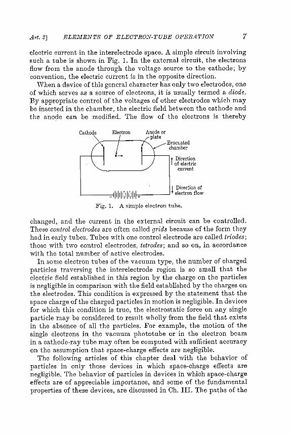
electric current in the interelectrode space. A simple circuit involvingsuch a tube is shown in Fig . I . In the external circuit , the electronsflow from the anode through the \Toltage source to the cathode ; bycon\7ention, the electric current is in the opposite direction .
When a device of this general character has only two electrodes, oneof which serves as a source of electrons , it is usually termed a diode.By appropriate control of the voltages of other electrodes which maybe inserted in the chamber , the electric field between the cathode andthe ano~e can be modified . The flow of the electrons is thereby
changed , and the current in the external circuit can be control led .These control electrodes are often called grids because of the form theyhad in early tubes . Tubes with one control electrode are called triodes ;those with two control electrodes , tetrodes ; and so on , in accordancewith the total number of acti \Te electrodes .
In some electron tubes of the vacuum type , the number of chargedparticles tra \7ersing the interelectrode region is so small that theElectric field established in this region by the charge on the particlesis negligible in comparison with the field established by the charges onthe electrodes . This condition is expressed by the statement that thespace charge of the charged particles in motion is negligible . In devicesfor which this condition is true , the electrostatic force on any singleParticle may be considered to result wholly from the field that existsin the absence of all the particles . For example , the motion of thesingle electrons in the vacuum phototube or in the electron beamin a cathode -ray tube may often be computed with sufficient accuracyon the assumption that space -charge effects are negligible .
The following articles of this chapter deal with the behavior ofparticles in only those de\Tices in which space -charge effects arenegligible . The behavior of particles in devices in which space -chargeeffects are of appreciable importance , and some of the fundamentalproperties of these devices , are discussed in Ch . III . The paths of the
7ELECTRON-TUBE OPERATIONArt . 2] ELEMENTS OF
Cath Electron AnoEvacuatedchambert Directionof electriccurrent
! Direction of- IIIIIIIIIIII!I + electron flowFig . 1. A simple electron tube.

F = - Q grad E. [ 11 ]
* Quantities that are vectors in space are printed in boldface script or roman (upright )type.
9 N . H . Frank , Introduction to Electricity and Optics (2nd ed.; New York : McGraw -Hill Book Company, Inc ., 1950), 1- 14.
8 ELECTRON BALLISTICS [Ck. I
Eq . 9 may be written in the form
F = ma ,or d21F =mdt2'
If the particle is free to mo \Te, it is accelerated according to theequation
[12]
[13]
charged particles in electrostatic and magneto static fields discussed inthis chapter are similar in many respects to the trajectories of projectiles
in the gravitational field of the earth - hence the chapter istitled electron ballistics .
3 . MOTION OF CHARGED PARTICLES IN ELECTROSTATIC FIELDSIN V _~ CUUM
Because the charged particles of interest in electron tubes are sosmall in comparison with the dimensions of the tubes in which theymove, the forces that act upon them may be calculated as though theparticles v;..ere concentrated at points . Thus the force exerted on sucha Particle by an electrostatic field is given by
where F = Qg , [9]
F is the force acting upon the charged particle ,
Q is the charge carried by the " particle ,
. 6' is the electric field intensity at the location of the particle .
The quantities F and g in this relation are vectors .* Equation 9specifies (a) that the magnitude of the force is the product of themagnitude of the field intensity and the charge and (b) that thedirection of the force is that of the field if the charge is positive andis opposite to the direction of the field if the charge is negative .
If E is the potential at each point in the tube , taken with respect toany arbitrary zero of potential , the gradient9 of E , written grad E ,is a vector oriented in the direction in which E increases most rapidlyand whose magnitude is the rate of change 'of E with distance in thisdirection . Since
g = - grad E , [ 10]

9IN ELECTROSTATIC FIELDSArt . 3] J.110TION
d2X Qdi2 = ;n6x,
~ = 2. 611'dt2 m
~ = 2. 6zodt2 m
~[17]
~[18]
~[19]
where
F is the total force acting on the particle ,
m is the mass of the particle ,
a is the acceleration of the particle ,
1 is the displacement of the particle from an arbitrary origin ,
dl is the differential displacement of the particle , and is along
the path the particle traverses ,
t is the time measured from an arbitrary reference instant .
The quantities F , a , and 1 are v'"ectors , and Eqs . 12 and 13 relate both
magnitudes and directions , just as do Eqs . 9 , 10 , and 11 .
The only forces experienced by a particle moving in an evacuated
tube are those caused by the fields of force , such as electric , magnetic
or gra "\Titational fields , that may be present . In this article it is supposed that no field other than an electrostatic one is present ; therefore
, Eqs . 9 , 11 , and 13 may be combined as
d21
Qg = m dt2 ' [ 14 ]
or d21 Q [ 15 ]- = - 6 ,dt2 m
and ~ = - ~ grad E . [ 16 ]dt2 m
Equations 15 and 16 do not involve any co -ordinate system . They
may be expressed , however , in terms of any desired co -ordinate
system . If , for example , a set of rectangular co -ordinate axes is
chosen , the equations may be used to express the relations a.mong
the components of the vectors along these axes . Thus , if 6x , 61 / ' and
6z are the components of 6 along the x , y , and z axes , respectively ,
Eq . 15 becomes

If the initial velocity and position of a charged particle and thepotential distribution in the tube are known , it is possible to determinecompletely the motion of charged particles in electrostatic fields , provided
the differential equations just derived can be solved. However ,
unless the field is uniform , at least one of the field components varieswith the co-ordinates , and the equations are nonlinear . In addition , ifthe speed of the particle is a large fraction of the speed of light , themass becomes a function of the speed of the particle , and the equationsare again nonlinear . The solution of the nonlinear equations may oftenrequire the use of graphical , numerical , or mechanical methods .
An alternative and powerful attacl { on the problem of the motionof a charged particle in electrostatic fields, which yields much information
about the motion , is the use of the principle of conservation of
energy to derive a relation between the potential and the speed of acharged particle at any point . Let the particle travel from the pointPI to the point P 2' The differential displacement of the particle alongits path is dl . Since the kinetic energy acquired by the particleequals the work done on the particle by the field ,lo
10 For an explanation of the dot -product notation used in the integral of Eq . 26, seea textbook such as N . H . Frank , Introduction to Electricity and Optics (2nd ed.; NewYorl { : l\IcGraw -Hill Book Company, Inc ., 1950), 107.
ELECTRON BALLISTICS [Ck. I10
[20]
[21]
[22]
[23]
[24]
[25]
and
LP2! mV22 - ! mt'12 = F . dl ,PI
[26]
Since the components of grad E along the co-ordinate axes are therates of change of E with distance along these axes,
a Ex component of grad E = a-;- '
a Ey component of grad E = ~ ,
uy
a Ez component of grad E = ~ '

and this form may be used to find the speed of a particle at any pointon its path if the speed at anyone point is known . In particular , if thepoint PI is taken as the point at which the particle starts from rest ,and if the potential of this point is chosen as the reference for potential ,then VI and EI are zero . Since the point P 2 may be any point on thepath of the particle , the subscripts may be dropped from the symbolsrelating to it to give the very useful relation
paintzero .
11Art. 3] J.l:l0TION IN ELECTROSTATIC FIELDS
"[29]V2 =
J~ ~[30]v =
where the potential isfor a particle that starts from rest at a
where
V2 is the speed of the particle at P 2'
VI is the speed of the particle at PI ,
In Eq . 26 and the equations derived from it , the assumption ismade that the speed of the particle never exceeds a small fraction ofthe speed of light . If the speed of the particle is large enough, the massbecomes a function of the speed, in accordance with Eq . 4, and thekinetic e~ergy is no longer given by imv2. The value of F from Eq . 9may be substituted to give the result
i P2! mV22 - im V12 = Q g . dt = - [QE2 - QEJ , [27]PI
where
E2 is the potential at P 2'
El is the potential at Pi ,
Equation 27 may be written
{.mv12 + QE1 = -~mV22 + QE2 , [28]
which states that the sum of the kinetic energy and the potentialenergy of the particle does not change during the motion . Equation 28could have been written directly , since it is a statement of the principleof conservation of energy for a charged particle in an electrostaticfield .
An alternative form of Eq . 28 is

12 ELECTRON BALLISTICS [ChI
From Eq . 30 it appears that the speed and the kinetic energy of aparticle moving in an electrostatic field depend only upon the totalpotential through which the particle mov~es, and not upon the mannerin which the potential varies along the entire path . It should be noted ,ho\,'"ever, that the direction of the particle velocity and the timerequired for the particle to move a given distance do depend uponthe distribution of the electric field . These quantities cannot bedetermined without the use of information in addition to thatcontained in Eq . 30.
In the remainder of this article the differential equations and therelation between potential and ,:relocity are used to determine themotion of charged particles in certain configurations of electrostaticfields which ha ,:re plane symmetry and are of particular interest inelectron tubes . It is fortunate that approximate plane or cylindricalsymmetry exists in many practical electronic devices , because thesymmetry makes determination of the electronic motion in themrelatively easy.
3a. Uniforn1, Field ,. Zero Initial "Velocity. In Fig . 2a, l;; and parethe cathode and plate , respectively , of a Simple electron tube . Theseelectrodes are assumed to lie in parallel planes separated by adistanced
, which is very small relati ,re to the dimensions of the electrodes, so
that they may be treated as infinite parallel planes. If a constant voltage is applied across these electrodes, the potential gradient and the
field between the plates are constant in time and uniform in space , andare directed perpendicularly to the plates . The potential of the platewith respect to the cathode* is called eb. Alternatively , eb is the voltagerise from the cathode to the plate , or the voltage drop from the plateto the cathode. If eb is positive , the vector 6 is directed from theplate to the cathode , and the potential gradient from the cathode tothe plate ; physically , the force on a positively charged particle betweenthe electrodes is in a direction to move it toward the cathode . Because
of its negative charge, however , an electron tends to move fromcathode to anode .
The rectangular co-ordinate axes in Fig . 2a are dra\vn so that theorigin is located in the plane of the cathode , and the x axis is perpendicular
to the electrode surfaces . The potential distribution in thA tl ] hA
can therefore be described by the graph in Fig . 2b. Suppose that acharged particle is set free at the origin of co-ordinates in the surface ofthe cathode with zero initial ve Jocity , and the equations of its motionare to be found . Under these conditions , 6x equals - (eb/d); and
* In general , in this book , constant voltages and currents are denoted by capitalletters and variable voltages and currents by lower -case letters . The lower -case eb isused here in preparation for a future use in which eb becomes a variable .

since the field is along the x axis only , 6y and 6 z are both zero.
k
j . - - - d - - - . J PCathode k
(a) Electrode configuration (b) Potential distribution
Potential distribution between infinite , parallel -planeelectrodes .
where v is the speed of the particle evaluated at any point on its path .In this integration it is assumed that the speed of the particle is nevermore than a small fraction of the speed of light , so that the mass ofthe particle may be considered a constant .
13Art . 3] .J.' :lO T I OR IR ELECTROSTATIC FIELDS
d2X Q eb- - - - -
dt2 - md ' [31]
[32]
[33]
d2ydt2 = 0,d2Zdt2 = O.
Fig. 2.
I 2 ~ t2,x=-2md [35].
Thus either Eqs. 17, 18, and 19 or Eqs. 23, 24, and 25 become
In addition , x , y , z, dxldt , dyldt , and dzldt are all zero " ,hen t is zero.Since the particle starts at rest and is not accelerated in the y or z
direction, its motion is confined to the direction along the x axis. Byintegration of Eq. 31 and use of the initial conditions to evaluate theconstants of integration, the equations that describe the motion of theparticle are found to be
v = - ~ it , [34]
14 ELECTRON BALLISTICS [Ok. I
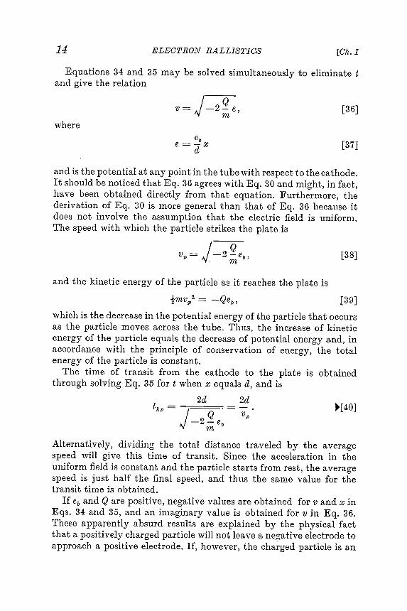
Equations 34 and 35 may be solved simultaneously to eliminate t
and give the relation
v = J4 , [ 36J
where
e
e = ; jx [ 37J
and is the potential at any point in the tube with respect to the cathode .
It should be noticed that Eq . 36 agrees with Eg . 30 and might , jn fact ,
have been obtained directly from that equation . Furthermore , the
derivation of Eq . 30 is more general than that of Eq . 36 because it
does not in "~olve the assumption that the Electric field is uniform .
The speed with , , ' hich the particle strikes the plate is
vp = J ~ b ' [ 38 ]. m
and the kinetic energy of the particle as it reaches the plate is
imvp2 = - Qeb ' [ 39 ]
which is the decrease in the potential energy of the particle that occurs
as the particle moves across the tube . Thus , the increase of kinetic
energy of the particle equals the decrease of potential energy and , in
accordance with the principle of conservation of energy , the total
energy of the particle is constant .
The time of transit from the cathode to the plate is obtained
through solving Eq . 35 for t when x equals d , and is
2d 2d " [ 40 ]
tkp = j - - Q - = ~ .- 2 - ebm
Alternatively , dividing the total distance traveled by the average
speed will give this time of transit . Since the acceleration in the
uniform field is constant and the particle starts from rest , the average
speed is just half the final speed , and thus the same value for the
transit time is obtained .
If eb and Q are positive , negative values are obtained for v and x in
Eqs . 34 and 35 , and an imaginary value is obtained for v in Eq . 36 .
These apparently absurd results are explained by the physical fact
that a positively charged particle will not leave a negative electrode to
approach a positive electrode . If , however , the charged particle is an

15IN ELECTROSTATIC FIELDSMOTIONArt . 3]
[41]
[42]
[43]
[47]
2d .tkp = Vk + Vp
electron or other negatively charged particle , Q is itself negative ; and
if eb is positive , v is real , x is positive , and the equations describe
correctly the movement of the elec ,tron toward the plate .
3b . Uniform Field ,. Initial Velocity in the Direction of the Field . In
some electronic devices the charged particles cannot be considered to
start from rest at the cathode . Consideration of the initial velocity at
the cathode is required , for example , in an analysis of the motion of
an electron in a vacuum diode , as discussed in Ch . II , or in a multielectrod
~ device in which an electron set free at one electrode acquires
a , \Telocity by moving through a potential difference bet ...veen one pair
of electrodes and then enters the electric field between two other
electrodes .
If a particle starts from the origin at the cathode in Fig . 2 with an
initial v ~ elocity that is in the direction of the field and has a magnitude
vk , then , x , y , z , dyfdt , and dzfdt are zero when t is zero , but dx 'fdt
equals Vk when t is zero . The equations of motion obtained by
integration of Eqs . 23 , 24 , and 25 are then
~ - - ~ ~
dt2 - md '
dx Q eb
dt = - md t + Vk '
1 Q eb
x = - - - - t2 + Vkt2md . ,
y = 0 , [ 44 ]
z = o . [ 45 ]
The speed with which the particle strikes the plate , Vp , may be
determined through application of the principle of conservation of
energy . Accordingly , the kinetic energy of the particle as it strikes the
plate equals the sum of the initial kinetic energy and that acquired
from the field . Thus ,
imvp2 = - Qeb + imvk2 , [ 46 ]
whence
J
2Qeb
v = _ _ + V2 .p 11 ~ k
The time of transit from cathode to plate , tkp , is the ratio of the
distance to the average speed . Since the acceleration is uniform , the
average speed is the average of the initial and final speeds . Hence ,
[ 48 ]

16 ELECTRON BALLISTICS [Ok. I
d-: = 2 6t + 01 ,dt m [49]
[50]
[51]
dydt = O2 ,dz
de = O3'and
x = ! g €t2 + 01 t + 04 ,2my = 02t + 05 ,
Z = 03t + 06.
x = 7y2 + sY + 9, [55]
3c. Uniform Field ,' Any Initial Velocity. Ifin the tube of Fig . 2 theinitial velocity of the particle is considered to have an arbitrarydirection , and if for further generality the origin of co-ordinates is supposed
to have any location , the general equa'tions for a charged
particle moving in a uniform field aligned with the x axis are obtained .Under these generalized boundary conditions Eqs. 17, 18, and 19 yieldby integration
The constants of integration , 01 through 06, have values that dependupon two sets of boundary conditions , of which each set is expressiblein terms of the three co-ordinates ; for example , the boundary conditions
are often the initial velocity and initial position of the particle .
Note that the motion of a charged particle in a uniform electrostaticfield is strictly analogous to the motion of a material particle in auniform gravitational field , since the acceleration imparted to theparticle by either field is constant . The path of a charged particle , likethe trajectory of a projectile , is in general a parabola . If the initialvelocity is in the direction of the field , or is zero, the parabola degenerates
into a straight line . This fact is seen at once if Eqs. 52, 53,
and 54 are recognized as the parametric equations of a parabola . Theequations of the parabola may be placed in a more commonly encountered
form if the co-ordinate axes are so chosen that the x- y
plane is in the direction determined by the field and the initial velocity ,and the particle starts from a point in this plane . It is easy to showthat the motion is then entirely in the x- v plane. The constants 03and 06 become zero, and the motion is described by the displacementsx and y . If the value of t given by Eq . 53 is substituted into Eg . 52,there results an expression of the form
[52]
[53][54]

17FOR N Uill E R I CAL COJ.1:lP U T A T I ON SUNITSArt . 4]
This form is recognized as thewhere O7' O8' and 9 are constants .equation of a parabola .
rationalized units .11 See also E . E . Staff , M.I .T ., Electric Circuits (Cambridge, Massachusetts: The
Technology Press of M.I .T .; New York : John Wiley & Sons, Inc ., 1940), 754- 756.
4 . UNITS FOR NUMERICAIJ COMPUTATIONS ; THE ELECTRON VOLT
In the numerical solution of any practical problem involving themotion of charged particles in electrostatic and magneto static fields,the question of the units to be used always arises. Since the motion ofthe particle is essentially a problem in mechanics, it is desirable to usea system of units in which measurement of the motion , or the forcesthat give rise to the motion , is convenient , as well as one in which theelectrical units are of convenient size . The internationalmeter -
kilogram -second (mks) system provides such units , and all the derivedequations in this book hold when numerical values substituted intothe equations for tile quantities involved are expressed in the mksrationalized system or any other self -consistent rationalized systemof units . However . with minor alterations * the equations also hold
for any self-consistent un rational ized system, such as the cgs absoluteelectromagnetic (aem ) system or the cgs absolute electrostatic (aes)system. These systems have been, and still are, used frequently in theliterature of electronics , and familiarity with the commonly encountered
conversion factors for converting from one system tiOanother is desirable . A table of conversion factors is given in
Appendix B .11For illustration , consider the expression
F = 6Q = ma. [56]
In the three previously mentioned systems of units this equation maybe written in the following three ways :
For the mks system , [57]
[ fie U'lans = [6 ]vOlts per ?1~eter [Q]coulon~bs = [m ]kilogramS [a ]meters per sec per sec.
For the aes system , [58]
[F ]dynes = [6 ]statvolts per C1/1, [Q]statcoul O11~bs = [m ]grams [a]cm per sec per sec.
* See Appendix B for an explanation of the distinction between rationalized andun rational ized units . Substitution of Ev/ (41T) for ElI and D / (41T) for D are the only
changes necessary to convert the particular equations included in this bool \: into theform for which un rational ized units are applicable . Only equations that involve ElI and
D explicitly need be changed . All others are suitable for either rationalized or un -

~
P " " ~
~
~
~
~
< : ~
f - j ' " - ; ; ; 0 " ' e . . ~
>
t : I : j ~
1 : 1 >
0 , 3 . 5 . S
~ ; . ~
5 . Q
0 S
0 " ' ~
1 - 1 ~
~
CD
9 root
' CIl
1 - . - 1 <
. - t ' ~
~
~ . ~
L - - I ; 5 CIl
~
~
~
~
<
~
~ . . . . . . ~
1 - 1 ' ) . . . . . I - i ~
~
0 Co
Q
< : ~
root
' : - ' \ . 1 CD
~
. . . . . . CIl
cot
- CD
, ? ; o Q
0 I - , ~
' . . . . . . . ~
CD
CD
! - 3 CIl
~
CD
[ ; . . ~
CD
~
~
~
~
! : j 1 - . - 1 I - i
.. . . . C
D
, . . , CD
. . . . I - i , . . , . . . . . . . . . . CIl
" " ~
I ' " ' f . H
H
0 C1
' - . . " ~
" " ' ; ' - H
CD
I - i . . . . ; : >
l - ' - . J
!- h ~
! : j 0 " " ~
CD
0 ~
~
~
. . . . . ~
Q
01
~
Q
. . . . w
~
. . . . . ' " d : = ' . p . . CD
~
CIl
~
r - - , ~
D
CD
~
. . . . . " " , ~
~
~
~
~
. . . ~
~
~
~
00
0 0 . . . . . ~
~
0 " ' ~ . ~
CD
o , . - t ' CIl
~
CD
CIl
~
P " "
; ~
o ' 0 ~
C1
' - ~
CD
S
II " ' ~
g . . ~
P ' S
~
~
~
~
~
CD
; . C1
' - I : f ' ) H
~
' f1 ' ~
~
' C ; ~
: ~
L - - I CD
Q
0 ~
1 - 1 ' ) ~
P ' CD
. . . ~
0 ~
~
H
<
~
0 0 p . . " CIl
CD
CD
' wi
' ~
~
,ol - l ' ) ~ ro
ot' ~ : : : I ' ) Q
QC
Il
I I ~ p . . I - i ( ) q ~ " " ' CD
8r
: - . . . . ~ CIlC
D
' - + " ) I - i ~ ~ ~ ~ ~ S
- : ! ' CD
; ~
o ' P " " . . . . . . . ' ih
~
P " " 0 ~
CD
CD
0 ~
~
V " ) I - i CD
I : f ' ) Q
CIl
: : ' : 0 CD
( ' : to
~
~
~
~
! : j
D
~
~
~
CD
C1
' - 0 0 1 - 1 ' ) ~
~
p . . ~
. . . . . 0 " ' I - i " " " . . . . . . . . . . . ~
p . . p . . 0 CD
~
I - i S
q ~
P " " 01
P
~
~
~ . CIl
S
~
CIl
~
~
~
~
~
CIl
~
~
CD
p . . 0 CIl
~
0 " ' ~
6 ~
~
. . . . . CD
0 C1
' - CD
~ oo
II CIl
~
I - i ' C ; . . . . . ' " d dQ
. r - - , Q
~
P " " ~
0 Q
root
' Q
CD
C1
' - S
( ) q CD
~
CD
~
CIl
~
~
1 - 1 ' ) P " " 0 " ' ~
~
r - - , ~
~
~
~ . ~
S
g P " " ~
~
I : f ' ) CD
~
~
~
P " " r - - , 5 ~ . I : f ' ) 0 " ' ~ . ~
Q ' >
~
. . . . . p . . ~
~
~
~
CD
CD
: : r ~
~
root
'
P" " ~
~
. . . . . C1
' - L - - I ~
0 ~
~
c - t - CD
~
CIl
I - i 0 ' f1
- . , CD
I - i I - i CIl
. . . . . S
CD
P
~
CD
CD
p . . LIC
D
~
. . . . . CD
P " " ~
~
root
' ~
root
' I - i ~ . ; = : b g - 0 " ' ~
' ii ; - ' ~
~
1 - 1 ~
CD
CD
~
. ~
~
~
- g ~
CD
01
~
?
~
~
' g CD
0 " ' ~
e : ~
~
~
' C ; x ~
C1
' - CD
~ . ~
~
p C1
' - . . . . . CIl
~
~
CD
~
' g ~ < t >
. . cn
~
~
' t6
~ c : o ~
~
root
' ( D
~
< t >
~
CIl
II ~
< t >
0 ~
I p . . root
' S
root
" " CIl
~
0 s ~
< t >
~
~
p . . P " " ~
CD
CD
P : J ~
CIl
' [ J ; ~
~
tI : j
) P " " ~
. . . . . ~
0 I - ' . P " " ~
CIl
1 - 1 ' ) 0 CIl
0 ~
~
CIl
. . . . . ~
. . . . . CIl
P " " ~
t ' i
~
< t >
Q
p . . 8 ~
~
r - - , g ' . . g root
' 0 < t >
p . . ~
II ~
t : : j ~
<
1 - 1 ' ) ~ : $ J ~
~
~
. . . . . g p . . r ; ! ; . ~
0 CD
~
tI : j
.. C
D
0 0 ~
~
. - t ' ~
~ ~ . ~
~
< t >
CIl
r - - , < t >
0 " ' ~
0 Q
~
~
CD
~
~
~
( ' : to
0 CD
. 1 - 1 ' ) ~ ; = : C ' . )
)
~
1 - 1 ' ) - : : : ~
I ; ; ; : - J Q
~
p . . ~
0 ~
~
CD
~
Q
< t >
. O " ' : : : i : ' 0 " " ' . . . . . ~
ro
< : ~ . ~
CIl
~
~
r - - , t . . j
l. . . . g ~
CD
~
0 0 : ; 0 c - t - < t >
~
I - i ~
' " d p . . L - - I 0 Q
< t >
CIl
~
~
~
~
0 I - i 0 Q
CD
" " . ~ . . . . . ~
' ; : Ij
CD
~
I - i ~
p . . ~
S : ; . - root
' ~
CD
: ; . - I - i I : f ' ) ~
~
~
01
p . . ~
~
p . . ~
~
. . . . . ~
~
~
. . . . . c - t - ~
a
) ~
~
< t >
root
' ~
~
0 " ' , ; . . . . 0 " ' ' ; ; ; ~
CIl
0 0 ~
root
' 0 ~
' " d ~
~
~
ro . . . . cot
- " ' " <
~
CIl
~
~
) . . . . . . . . . . . Q
~ ! : j S
' " . . . . . ~
< t >
~
~
<
I - i 0 : ; ~
CIl
. . . . . ~
CD
I - i ~
root
' ~
~ . CIl
! : j ~
0 CIl
~
g . . . . . .
. 0 0 ro
ot' ~
P
~ , ' " ~
' " ! : j 0 " " . ; : ; : . . . . . . CD
~
. . . . . . I - i CIl
. . " P " " b " ' ~
p , . . , . . . . . . . . . . ' " d . . . .
; ~
~
6 r +
0 " ' ~
g < t >
~
? ? ; . . . p 1 - 1 ' ) ~
~
~
~ . ~
<
~
o ' ~ . ~
< t >
~
< t >
~
< t >
< t >
~
~
' " d ~
ti : I
;. ' f1
~
~
0 ~
CIl
r - - , : ? - ' : ; . - P : J g r - - , ~
r +
p . . , . . o ~
~
~
~
p . . ' ~
~
~
0 " ' ~
' " d ' ( t ) " " p . . ~
~
p . . ~
~
go
~
)
P " " " . p . . CD
~
b " Q
~
< t >
0 " ' ~
~
( ) q CIl
<
~
. . . . . ~
~
I - i Q
Q
~
CIl
- . - . . . . . . ~
- ,
~
~
~
~
~
~
~
g ~ . S ' ~
8 ~
< t >
~
~
~
; ~
S ' S - ' ; ; ! ; . ~
~
s : ~
~
' 4 " ~
~ . g . 5 . ~
~
II t
0
! - h CD
P
~
- . , root
' ~
~
CD
. co . . . , . . , . . . ! : j Q
CIl
CIl
0 ~
C1
' - p . . r - - , ~
. . ;
.. ~
~
I - i I - i , . . o . . . . . [ S . r +
CIl
[ ~
' " d ' ; ; ! ; . ~
< t >
~
v , " , ~
~
S - ~
CIl
~
CD
~
~
( ) q 00 ' ~
P " " ~
~
1 : 3
~
~
0 $ ~
' go
( ) q ' g " ~
~
: 9 : 6 q ~
~
~
g ~
~
~
~
' ( t ) " " ~
o ' ~
5 . p . . ' " d ~
0 ~
~
r" ' < t >
1 - 1 ' ) ~
C1
' - g . aq
~
0 " ' ~
X
< t >
' " d . . , ' ! g ~ . . . . . . ~
~
~ I - i Q
< t >
~
~
. . , ' ! CIl
CIl
~
6 < t > ; ' ~
Vi
.. H
C
. . . . . root
' x . . . . . . < t >
~ . . . . < t >
~
" , ~
~
! : j " " " ~
~
. . . . . C1
' - . . . . . . . . . . .
) ~
I - ' ~
~
: : ' : . 0 " ' < t >
' pi
u ~
~
I - i ~
g . ( ) q . . . . ~
~
CIl
~
P
v ~
~
0 ~
~
I - i ~
~
< t >
~
.
< ? ; ~
. . . . . < t >
~
I - ' p . . Q
< t >
~
Q
0 " ' 0 . f - j . . . . . P " " ~
CIl
P " " < t >
I - i < t >
< t >
~
0 " ' ~
. C
Il
~
~
. - t ' CIl
~
0 CD
~
p . . x ~
0 " " " ' " P " " ' " d ~
< t >
p . . ~
0 " ' Q
~
P ' S
p . . S
~
I - i L - - I
:. ~
I - ' ~
' f1
~
~
. - . J ~ . CD
6 I - ' ~
~
~
~
8 . ~
I : f ' ) S
< t >
0 w ' ~
CIl
S
< t >
5 . ~
~
g
: c - t - ~
in
~
w ' ~
' " d ~
: : ' : ~
~
CIl
~
P " " ~
~
< t >
~
~
r +
CIl
0 ~
~
P : J ~
~
~
~
! < t >
~
< t > . . . . . p . . ' " d ' f ; ; - J q I - i 0 " ' ~ . . . . . . Q
CD
c - t - c - t - < t >
P - CIl
S
I - i CIl
~
< t >
. . . . . CD
. . .
) S
~
~
~
~
~
CD
~
~ . I - i I : f ' ) ~
CD
0 " ' ~
~
CD
~
< t >
~
~
0 ~
' [ J ; ~
CIl
~
0 " ' < : ~
$ ~
p . . ~
~
0 ~
0 ~
~
~
~ ' . . . . . . Q
r +
~
CIl
~
~
~
~
: 0 p . . ~
~
~
~
p . . ~
~
~ . ~
~
~ . ~
. . . . . ~
C1
' - < t >
~
- g ~
~
< t >
g ~ . I - i ~
'1 - 1 ' ) < t >
<
p . . ~ . ~
0 " ' ~
~
~
< t >
~
~
~
I - i ~
p . . C1
' - ; : >
~
p " " " ' " I - i < ' ! . - t ' 0 ~
)
I - ' CD
c - t - 0 " ' CD
0 ' : = ' ~
C1
' - CIl
~
( ) q P " " ~
. . . . . ~
~ . . . . . . . . . . CIl
~
0 " ' ~
~
I ~
~
S
p . . ~
o ' < t >
~
~
~ . ~
~
c - t - ~
p . . < t >
< t >
~
S
~
c - t - Q
~
~
~
. . . . . ~
.
I- ~ . . . . . ~
~
Q
0 CIl
~
( ' : to
~
Q
CD
. . . . . . P " " . . . . . CIl
~
~
, - . ,
:; . - ~
~
~
0 . . . ~
~
0 ' g ~
~
I - i ~
~
' g a - : ~
~
~
S - c - t - g - r ; ! ; . ~
~
' 1 ? ; : 5 . r +
~
r - - , ~
: C
Il
~
~ . ( " \ ~ . ~
~ . . , ' ! I - ' ~
. . . . . [ ; . . 0 < t >
CD
~
. . . . . ~
I - i ~
I - i ~
I - i ~ ! : j P " " P " " ~ .
~
. . " ~
~ . . . . L - - I I ' < ; L - - I . . " CIl
, . . , L - - I ~
CIl
. CIl
~
CIl
. < t >
~
< t >
I P
~
< t >
< t >
L - - I ~
18 ELECTRONBALLISTICS

Art . 5 ] DEFLECTION IN A CATHODE - RAY TUBE 19
When the value for the ratio of the charge to the mass of the electron
given in Eq . 3 is substituted in Eq . 30 , the speed of an initially stationary
electron is given in terms of the potential difference through
which it moves , as
v = 5 . 94 X vEmeters per second , ~ [ 63 ]
where E is in volts . This equation holds only for speeds small compared
wit .h that of light . The energy of the electron is then
imeV2 = EQe [ 64 ]
= 1 . 60 X 10 - 19 X E joule . [ 65 ]
Since for reasonable values of voltage the energy of the electron is
extremely small , and since its energy is directly proportional to the
potential difference through which it moves , it is convenient and
customary to adopt as a unit of energy the electron volt , abbreviated
to ev , which is the kinetic energy that an initially stationary electron
acquires by moving through a potential difference of one volt . Thus
1 ev = 1 . 60 X 10 - 19 joule . ~ [ 66 ]
The electron volt serves as a convenient unit of energy for calculations
involving the charge of an electron just as the joule , which might be
called the coulomb volt of energy , serves for calculations involving
coulombs of charge , or involving amperes .
5 . DEFLECTION OF THE ELECTRON BEAM IN A CATHODE - RAY
TUBE
One application of the analysis of the behavior of charged particles
in an electrostatic field is in some types of electron - beam tubes . As a
class such tubes include devices for many different purposes , as summarized
in Fig . 3 . They find extensive application , especially in television
! 2 radar , 13 and in experimental studies of time - varying phenomena
. 14 The oscilloscope tube in particular is indispensable for the
12 V . K . Zworykin and G . A . Morton , Television ( Ne \ v York : John \ " " iley & Sons , Inc . ,
1940 ) ; D . G . Fink , Television Engineering ( 2nd ed . ; Ne \ v York : l \ IcGraw - Hill Bool {
Company , Inc . , 1952 ) ; Scott Helt , Practical Television Engineering ( Xe \ v York : Murray
. Hill Books , Inc . , 1950 ) .
13 L . N . Ridenour , Editor , Radar System Engineering , l \ Iassachusetts Institute of
Technology Radiation Laboratory Series , Vol . I ( New York : l \ IcGraw - Hill Book Company
, Inc . , 1947 ) ; D . G . Fink , Radar Engineering ( New York : l \ IcGraw - Hill Book
Company , Inc . , 1947 ) .
14 J . H . Ruiter , Jr . , ""' Iodem Oscilloscopes and Their Uses ( New York : Murray Hill
Books , Inc . , 1949 ) ; J . F . Ryder and S . D . Uslan , Encyclopedia on Cathode - Ray Oscilloscopes
and Their Uses ( New York : John F . Ryder Publisher , Inc . , 1950 ) .

Fig
. 3 . Gen
eral
clas
sific
atio
n
of
elec
tron
- beam
tube
s
. ( Thi
s
char
t
is
take
n
from
" Sta
ndar
ds
on
Ele
ctro
n
Tub
es
Def
initi
ons
of
Ter
ms
, 1950
, " I . R . E . Pro
c
. , 38
( 1950
) , 428
, with
perm
issi
on
. )
~~ ELECTRO.LVBALLISTICS r- - .
~~
Gen
eral
clas
sific
atio
n
of
radi
o
beam
. form
ing
elec
tron
tube
s
~~
~ ]I
ruD
~)
fb
,0
}I

DEFLECTION IN A CATHODE-RAY TUBE
study of cyclic and repetitive transient phenomena in the audible - andlow radio -frequency range. High -speed oscilloscopes are available forthe study of nonrepetitive transient phenomena having durations asshort as a few millimicroseconds .
A photograph of a typical cathode-ray oscilloscope tube and itsinternal structure is shown in Fig . 4. The essential elements in this
and deflection .
Art . 5] 21
'rypical cathode -ray tube with electrostatic focusing(Courtesy Allen B . Du Mont Laboratories , Inc .)
1. Base 10. Conductive coating (connected in -2. Heater ternally to Az)3 . Cathode 11 . Intensifier gap
4. Control grid (G) 12. Intensifier electrode (A3)5. Pre-accelerating electrode (con- 13. A3 terminal
nected internally to Az) 14. Fluorescent screen6. Focusing electrode (AI ) 15. Getter7. Accelerating electrode (Az) 16. Ceramic gun supports8. Deflection plate pair (D3D4) 17. l' Iount support spider9. Deflection plate pair (D I Dz) 18. Deflection plate structure support
tube are as illustrated in Fig . 5. They comprise : (a) a source of electrons, usually a heated cathode ; (b ) an arrangement of electrodes
termed an electron g1ln , which serves to attract the electrons from the
cathode , to focus them into a fine pencil or beam of rays , and toproject them from the cathode down the major axis of the tube (hencethe name cathode ray ); (c) an arrangement of electrodes called deflecting
pla.tes, or of coils, as is discussed in Art . 7b, located beyondthe gun and used to deflect the electron beam ; and (d ) a target orscreen placed in a plane substantially perpendicular to the axis of thegun and coated with a phosphor such as willemite , Calcium tungstate ,or zinc silicate , which becomes luminescent when struck by theelectrons . The whole assembly is enclosed in a glass or metal container
. having a glass window , and the container is evacuated to a pressureof about 10- 9 atmosphere .

ELECTRON BALLISTICS [ChI
Electrons emitted by the hot cathode lc are accelerated to \vard thefinal anode p of the electron gun under the influence of the field established
by the anode -to -cathode ' Toltage Eb. In the very simple electrongun of Fig . 5 this anode is sho \vn as a disc \vith a hole in its center .
Although some of the electrons strike an electrode in the gun andreturn to the cathode through the source of Eb) many of them emergefrom the gun as a fine pencil of rays . In the absence of a voltage ed
f=:: lS_____----;jElectron Glass envelope - - "\gun - - - - -
- -
- -
- -
- -
C th d ( 10) Anode (p ) - - - \
a 0 e /\ .1_~ - - - - - - - Screens) \
r-~:=l" --- l-il Deflecting \{g -. -- ---~- ~~Q---- --~:t~s ~~-----______R ~, . - --....- I I\ L Electron - - - - I
- - - - - - - - - - - - t~ vp , ds- - U- + - - ,
~ III --------- ~ v ---___8Eb - - - - - - - I
- --
ed
21
Fig . 5. Electrostatic deflection in a cathode -ray tube .
bet ,,"een the deflecting plates d, the region beyond the gun is essentiallyfield free by virtue of the shielding effect of the metal container or of aconducting film on the inside of the glass container . The electronsthen pass down the axis of the tube through the field -free space andstrike the screen 8 at the point R with substantially the ,'"elocity theyhad on leaving the gun . (Secondary-emission phenomena invalidatethis statement when Eb is below about 100 volts or above about5,000 volts , the exact values depending on the screen material } 5 SeeArt . 12, Ch . II , for further discussion of this limitation .)
Since the initial velocity of the electrons as they leave the cathodecorresponds at the most to one or two electron volts (see Art . 5, Ch . V ),the '~elocity vp of the electrons that emerge from the gun is practicallythat corresponding to the change in potential energy EbQe. Thus ,from Eq . 30,
15 W. B. Nottingham, "Electrical and Luminescent Properties ofElectron Bombardment," J . App. Phys., 10 (1939), 73-82.
Phosphors under
22
)2 ~ E b .mev =11 [67]

Vd = ~ ~ ~in v d.e p
d Vas- =-,l Vps
After the electron leaves the region between the plates , its path is astraight line , since it is assumed then to be in a field -free space. If thestraight -line path is projected backward , it can be shown to passthrough the point 0 at the center of the plates . rrhen, by similartriangles ,
Art . 5] DEFLECTION IN A CATHODE -RAY TUBE 23
" Then a voltage is applied between the deflecting plates , the electrons acquire a velocity . component Vd perpendicular to the axis of the
tube as they pass through the field in the region between the plates .Instead of striking the screen at the point R , they now stril \:e it atsome other point , say S. On the assumption that the fringing of thefield at the edges of the deflecting plates can be neglected and thatthe plates are parallel to the axis of the tube , the field between theplates is .uniform and perpendicular to the axis of the tube , and arelation can be found for the deflection ds of the spot in terms of theanode -to ~cathode voltage Eb, the deflecting voltage ed, and thedimensions of the tube and electrodes .
The axial velocity component vp of the electron is unchanged by thedeflecting field , because the field acts in a direction perpendicular tothe direction of that component . The time required for the electronto pass through the deflecting plates is therefore
ta = llvp , [68]
where l is the length of the deflecting plates . During this time theelectron experiences a constant sidewise acceleration given by(Qelme)(eald), where d is the separation of the deflecting plates . Sincethis acceleration js constant , the electron acquires a component of
velocity Va perpendicular to the axis of the tube given by

24 ECho IELECTRONBALLISTICS
and elimination of vp by means of Eq. 67 gives1 lea
ds = "2 ls d ~ . [73]
The sensitivity of the tube ,,' ith respect to the deflection voltage istherefore
EI . d fl . . . . d ~ 1 l l ~ [ ]ectrostatlc e ection sensItIvIty = -.:. = - dE ~ . ~ 74ed 2 .lb
Since only the ratios of lengths and voltages are in \yolved in Eq . 74,the equation holds for any units of length or voltage , provided corresponding
quantities are measured in the same units . 'rhe sensitivity isevidently decreased as the accelerating voltage E b is increased .
Often another set of deflecting plates is provided , these plates beingso located along the axis of the tube that they deflect the spot as afunction of a second deflecting voltage in a direction perpendicularto the deflection caused by the first set of plates . l ' he path of the spoton the screen is then a function of the two deflecting voltages . If anunknown transient voltage is impressed on one set of plates , and avoltage of known waveform is impressed on the other , the path of thespot is a cur ,ye giving the unknown voltage as a function of the known .For example , one voltage may be made directly proportional to time ,whereupon the path of the spot delineates the waveform of the secondvoltage as a function of time , and the tube may serve as an oscilloscope
.
I1'or the tube . to be useful , the path of the spot must be visible or ofsuch a nature that it can be photographed . Hence the anode -to -cathode voltage Eb must be large in order to transmit sufficient energyto the phosphor to make its luminescence visible or sufficiently brightto be photographed . On the other hand , the deflection sensitivity ofthe beam decreases as Eb is increased , and a compromise betweensensitivity and luminosity must therefore be made . As a rule , theobservation or recording of transient phenomena of short durationrequires a large anode -to -cathode voltage and a consequent sacrificeof sensitivity .
In the foregoing analysis , it is assumed that the deflecting voltage ea,is constant ; yet the real utility of the cathode -ray tube is in the studyof phenomena involving a time variation of ed. If the speed of theelectrons is so great that the deflecting field does not change appreciably
while each electron moves through it , the deflecting field is
essentially an electrostatic field for each electron in the beam . However, although the electron is a very agile particle and the component
of \:-elocity vp is large , the time variation of ed is sometimes so rapidthat , during transit through the region between the deflecting plates ,

Although this time may at first appear to be small , it is not small compared '~'ith the duration of 10- 7 or 10- 8 second observed for many
transient electrical phenomena, or the period of a radio -frequencywavTe used for deflection . Hence it follows that the anode-to -cathodevoltage E b must be large not onljT to insure a bright spot on thescreen but. also to insure accuracy in the display of phenomena thatoccur in such a short time , for a large velocity vp and a correspondinglyshort time of transit through the deflecting plates are then required .16
The beam in a cathode-ray tube may be deflected by a magneticfield instead of an electric field . An analysis of magnetic deflection isgiven in Art . 7b.
&
P - ' ~
~
ro
P - ' ~
&
0 " ' &
w ' &
~
P" ' ~
~
. . . . . . 00
~ ~ ~
P " ' . . . .
~
p . . II < g ~
g ~
>
CD
0 ~
~
~
~
p. . ' " " " ' " " & " " " p - ' ' " ip - ' 00
0
~
C )
~
~
O ' " i P " ' CP
~
( ) q ~
: : : : 0 c - t - . . . . . . L - . J
,. . . , . " . ) . ' " i " ' " 00
00
' " i ~
:: : b ~
, , ~
P - ' c - te , ~
CD
CP
~
( )
~
&
t - . : J 00
~
r - t - 0 . . . . . . . . ' " " " ' " " CD
~
r - t -
0
. . - . ' ~ ' ~
0 c - t - - ~
( JQ
' " i
r- t - ~
X
p - ' 0 , . . . , ; : J 0 , . . . , . . . . . . 0
~' ; : J 00
~
( JQ
~
~
" - " " - " ~
,. . . , ~
~
c - t - ~
00
( JQ
() q . . . . p . . c - t - < : 0 " . , 0 ~
. . - . ' ~
'" i , ~
~
e - 0 , . . . , 0 " ' 1 -
~
~
- 1 &
~
0 0 " ' &
00
~
0 . . . . . . ~
.. . . . . ~
OJ
( ' ! ) ~
~
P " " ' - " ; : J c - t - ~
~
~. . . . P - ' ~
' " i P - ' ~
~
~
' ~
r- t - . . - . , X
~
p . . ( ) q 0 ( ) q 0 P - ' I - ( ' " i
II
~
' " i ~ , ~
~
0 " ' 0 . . . . . . ~
0 . . ~
' ( i > '
~
. . . . ~ : : : b c - t - 0 ~
~ . . - . ' ~
.. . . . . - . ' t - ' - ' 0 ~
~
. . - . ' P - ' ~
< : ~
' " i 00
0
,
00
~
~
p . . ~
~
S ' 0 . . P - ' c - t - < g ~
~
00
' " i . . - . ' &
~
; ; : . . . . . . 0 c - te . . 00
-J . o &
X
~
~
P " ' p . . ' ; ' " ~
~ . . - . , " " ~
t : : j
X
0 P " ' O ( ) q ~
< : ~ O &
t - ' 1
~
~ . . . . S
~
~
~
00
~
~
~ : : ; ' . . - . , ~
.. . . ( ' p < = i ' ; . . . . . . . . . . . . 0 " " " O
OS
Q
0
. . . . . . ttjp
- ' ~ ~ ~ t : + p - ' ~ ~
~
-- J ~
II ' " " ' c - t - 0 pOP
" ' 0 c - t - ~
. . . . . .
0
~
~
&
' " i ~
~ " - " ; : J . . . . . . v
II
. , - i - , 00
' " i ~
LA
0 oo " " i a
'" i " " 0 : , < p . . " " ' ~ . , - i - P - ' ~
.. . . 0 00
~
w ' ~
~
P " ' ~
~
P - ' ~ ,
,
~
- J P - ' ( ) q ~
. . - . , : : : b ~
~
~
P - ' a
0
- " - ~ . ~
0 ~
O . , - i - . . . . . .
-J , . I - ' 0 ~
; : J ; : : J " ' 0 P - ' . , - i - ~ " - " u
0
X
p . . ' 0 ~
~
- ; : ! : , 0 ~
00
0 ~
X
q . . . . OJ
t , . : J ~
~ , : ; . ~
~
~
t : +
~
I - . oot
P- ' 0 - J ~
ttj
0 ~
( ) q " - " ~ ' P " ' 0 ~
.. . . < : - - J , . . . ; : J 0 ' P - ' ' " i , . . . , ~
~
v . J
0
~
00 ' ~
~
. . . . . . ~
< : ~
00
~
I
. . . . . . S
& , . . . " " , . . . . . . op . . ~ ~ . : . . . .
<0 ~
00
" , CP
" " " e - 0 , . . . ,
00
. , - i - ~
' " i ~ 0 ~ 0 " ' ~ 00 ~
<g g - ~
' . ' : - ' P - ' q ~ ~ ~ ; ; : o . .
0
p . . 00
~
0 S
0 . ' t >
&
~
0 ' ~
~
. . - . ' ~
P " ' 0 ~
~
P " ' ~
~
: : : b
'" " ' 00 " . . . . ~
0 ~
~
0 ~
t- ' - ' . , - i - ~
" , . . - ! . . . . . 0
,
P - ' ' " i . . . . ' - . . ( ' p " ' " 0 . , - i -
~
oo " " i ~
. . . . . . 00
~ . . - . ,
0
~
~ . < : ? . mo
~ ~ & ~
~
0 ~ . , - i - ~ 0 ~ P " ' P " ' ( ) q
~
0 ~ oo ~ ~
' " i ( D ~ ~
., - i - ~
P - ' ~ ~
~ ~ oo ~
P" ' p . . 0 1 - ' 0 " " "
'" i ~
0 ~
00 , . . . , , . . . , ~
~
p . .
0
~ p . . ~ oo
00 ; : J0
r- - . ~
r - - . &
&
. , - i - , . . . , ~
~
c - t - : ; .
~
( ) q ~
P " ' P " ' P " ' SO
~ Op
- ' ~
L- . . I ; : : J " ' L - . . I ~
~
~
I . , - i - ~
~ . , - i - C , ) )
6. ELECTRON OPTICS
A second application of the analj "sis of the beha\Tior of charged particles in electrostatic fields is that of electron optics. The requirement
of a cathode-ray oscilloscope tube as well as certain other electronicdevices, such as electron microscopes, is that the surface concentrationof electron current leaving a given plane in the device be reproduced
. on some other plane with a surface magnification greater or smallerthan unity . Usually the magnification desired is less than unity inoscilloscope and television tubes but is greater than unity in electron
16 F. M. Gager. "Cathode-Ray Electron Ballistics." Communications, 18 (1938), 10;H. E. Hollmann, "Theoretical and Experimental Investigations of Electron Motions inAlternating Fields with the Aid of Ballistic l\lodeis," I .R.E. Proc.. 29 (1941), 70-79.

26 ELECTRO~V BALLISTICS [Ck. I
hasIII
optics18 has appeared andbecome of great importancethe design of electron microscopes
and cathode -ray tubes .
The term electron optics comesfrom the striking analogy thatexists between the behavior of
light when it passes throughrefracting media and the behavior
of electrons when they
pass through electrostatic or mag -netostatic fields .
As an illustration of this
region separates the two
microscopes .I7 In oscilloscope and television tubes , the magnificationis desired small in order that the electron concentration on the screen
be intense and the luminescent spot be small and bright . A small ,
bright spot makes possible greater detail in the figure traced out on
the screen and hence permits greater resolution of the data in electrical
transient studies . In the electron microscope , the magnification is
desired large for the same reason that it is desired large in opticalmIcroscopes .
Considerable attention has been given this problem during recentyears , ' with the result that a new branch of science called electron
Equipotential Equipotentialsurface 1 surface 2
- -- -
V2 sin r = vl sin i.,-
'" 2 Sr
vl sin
/ 1I
1!'ig . 6. Electron trajectory illustratingthe optical analogy .
analogy , consider that an infinitesimal
equipotential surfaces indicated in Fig . 6 . I ..et the potential of surface
I be EI and the potential of surface 2 be E2 ; and let the datum of the
potentials be the point where an electron that passes through point
P on surface 1 had zero ' ~elocity . When this electron reaches point P ,
its speed is
VI = J ~ . [ 77 ]me
If the angle between the path of the electron at P and the normal to
17 R . P . Johnson , " Simple Electron Microscopes ," J . App . Phys ., 9 ( 1938 ), 508 - 516 ;V . K . Zworyl { in , " Electron Optical Systems and Their Applications ," I .E .E .J ., 79( 1936 ), 1- 10; L . Marton , M . C. Banca , and J . F . Bender , " A New Electron Microscope ,"ROA Rev ., 5 (1940 ), 232 - 243 .
18 Several books that include the subject are : E . Briiche and O. Scherzer , GeometrischeElektronenoptik (Berlin : Julius Springer , 1934 ); I . G . l \Ialoffand D . W . Epstein , ElectronOptics in Television (Ne \v York : l \IcGra \v -Hill Bool { Company , Inc ., 1938 ) ; L . l\I . l\Ieyers ,Electron Optics (Ne \v Yorl { : D . Van No strand Company , Inc ., 1939 ) ; V . K . Z ",.orykin andG . A . Morton , Television (New Yorl { : John Wiley & Sons , Inc ., 1940 ) ; V . K . Z \vorykin ,G . A . Morton , E . G. Ramberg , J . Hillier , and A . W . Vance , Electron Optics and theElectron Microscope (Xe \v York : John ' Viley & Sons , Inc ., 1945 ).

the equipotential surface is denoted by i , the velocity component of theelectron perpendicular to the equipotential surface is Vl COS i . Thisvelocity component is in the direction of the electric field at P . Similarly
, the velocity component tangential to the equipotential surfaceand perpendicular to the electric field is Vl sin i as indicated in thefigure .
When the electron reaches the second equipotential surface itsspeed is
27Art. 6] ELECTRON OPTICS
J QeE2-:. 2'me [78]Vz =
If the path of the electron where it passes through the second equipotential
surface makes an angle denoted b ) T r with the normal to the
surface , the velocity component in a direction perpendicular to the
surface is v2 cos r and that tangential to the surface is v2 sin r . Although
in general the equipotential surfaces are curved , they may be
considered to be parallel planes in the region traversed by the electron
if they are sufficiently close together . Thus , while the electron is
passing through the infinitesimal region that separates the two surfaces
, the ' Telocity component t ' l sin i tangential to the surfaces does
not change , because it is perpendicular to the direction of the force
exerted on the electron by the electric field . Hence ,
VI sin i = V2 sin r , [ 79 ]
and
VI sin r y ~
- = - : - - : = -y - . [ 80 ]V2 SIn ~ E 2
The angles i and r are analogous to the angles of incidence and refraction
in optics , and Eq . 80 is equivalent to Snell ' s la \ v if it is considered
that V ~ and v : IiTz are analogous to the refractive indices 1] 1
and 1] 2 of the first and second media encountered by a light ray .
A comnlication arises \ vhen an attempt is made to formulate an
analogy bet \ V"een light optics and electron optics in an actual problem .
Instead of the uniform media with well - defined boundaries that are
. used in optical systems , the electric fields establis } led by the charges
on the electrodes in an electron tube present a continuously variable
refracting medium for electrons . In most electron - optical systems , the
field ~ e \ ~en though it is a complicated function of the radius and the
. position along the axis , possess es approximate cylindrical symmetry .
The distribution of such a field is not often readily calculable , but it

28 ELECTRON BALLISTICS [Ck. l
can often be found by an experimental method involving models ,19
and a point - by - point calculation is then practical for the determination
of the electron ' s path . Typical potential distributions for a space -
charge - free aperture lens and a double - cylinder lens are shown in
Figs . 7a and 7b . .
A second complication sometimes of importance is that the electrIc
field encountered by the particles consists not only of that set up by
the charges on the electrodes but also of that resulting from the
Metal diaphragm
j 1quipotentials
To . . . - - + To .cathode ' anode ; Cylinders
6a ' 6b
First anode
- - .~=-=-=-=-::.~:-=-: : - :
E2 > El
(a) Aperture lens (b ) Cylindricallens *
Fig . 7 . Electron lenses . *
charges of the particles in the interelectrode space . These modify the
total field to a degree depending on the amount and distribution of the
charge density in the space . This space - charge effect is frequently of
appreciable importance near the cathode of an electron tube but is
usually negligible in other regions . .
The point - by - point solution for the path of an electron in an electron
tube involves , first , a determination of the electric field intensity 6
throughout the region and , second , a determination of the motion of
19 P . H . J . A . Kleynen , " The Motion of an Electron in a T \vo -Dimensional Electrostatic
Field ," Philips Tech . Rev ., 2 ( 1937 ), 338 - 345 ; ED . l \ Ic Arthur , " Experimental Determination of Potential Distribution , " Electronics , 4 (June , 1932 ) , 192 - 194 ; H . Sa linger ,
" Tracing Electron Paths in Electric Fields , " Electronics , 10 (October , 1937 ) , 50 - 54 ;
D . Gabor , " Mechanical Tracer for Electron Trajectories ," Nature , 139 ( 1937 ) , 373 ;
V ,. K . Zwor ) 'kin and J . A . Rajchman , " The Electrostatic Electron Multiplier , " I .R .E .Proc ., 27 ( 1939 ) , 558 - 566 .
* This diagram is adapted from D . ' V . Epstein , " Electron Optical System of Two
. Cylinders as Applied to Cathode -Ray Tubes ," I .R .E . Proc . , 24 ( 1936 ) , Fig . 2 , p . 1099 ,with permission .

an electron in this field . During the time interval ~ 4 in which theelectron traverses a portion of its path ~ ll from , say , point PI wherel equals 4 to point P 2 where l equals l2' the change in its velocity component
in the direction of the field is
direction of the field is v t ~ t1
29J.,10TION IN .111AGNETOSTATIC FIELDSArt . 7]
�
~ VI = - ~ 61 ~t1 ,me [81]
~4 = J ( V t Lit, + ! ~ 6, Lit,2) 2+ (Vn ~t1)2 . [83]
mo\,ed is
The position of P 2 relative to PI and the velocity at P 2 are thereby
computed . During the next succeeding time interval ~ t2 , the increment of path ~ l2 trav ~ersed by the electron may be computed by a repetition
of the process ; the velocity V2 is resolved into components along
and perpendicular to the electric field intensity 62 encountered
between P 2 and P 3 and assumed to be constant over that interval .
By means of this point -by -point method the paths of rays through
the field can be computed through the use of field plots and computation
charts , and the refractive properties of the field can be deter ~
mined . Graphical and machine methods equivalent to the point - by -
point method are also used for a determination of the trajectory .20
7 . MOTION OF CHARGED PARTICLES IN MAGNETO STATIC FIELDS
A charged particle in motion in a magneto static field experiences
a force whose direction is perpendicular both to the direction of motion
of the particle and to 'the direction of the field . The magnitude of the
20 V . K . Zworykin and J . A . Rajchman , " The Electrostatic Electron Multiplier ," I .R .E .. Proc ., 27 ( 1939), 558 - 566 ; J . P . Blewett , G . Kron , F . J . Maginiss , H . A . Peterson , J . R .\ \ ' hinnery , and H ..' \ \ T. Jamison . " Tracing of Electron Trajectories Using the DifferentialAnalyzer ," I .R .E . Proc ., 36 (1948 ), 69- 83.
,vhere 61 is the electric field intensity encountered between PI andP 2' and .is assumed to be constant over the interval. If the velocity ofthe electron at PI is resolved into the components vn perpendicularand Vt parallel to the field, vn does not change during the timeinterval ~t1, and the speed of the electron at P 2 is
V2 = V Vn2 + (Vt + ~V1)2. [82]
During the interval ~t1, the distance the electron moves in thedirection perpendicular to the electric field is vn ~t1, and that in the
+ i- ~ 61 ~t12. Thus the total distance- ine
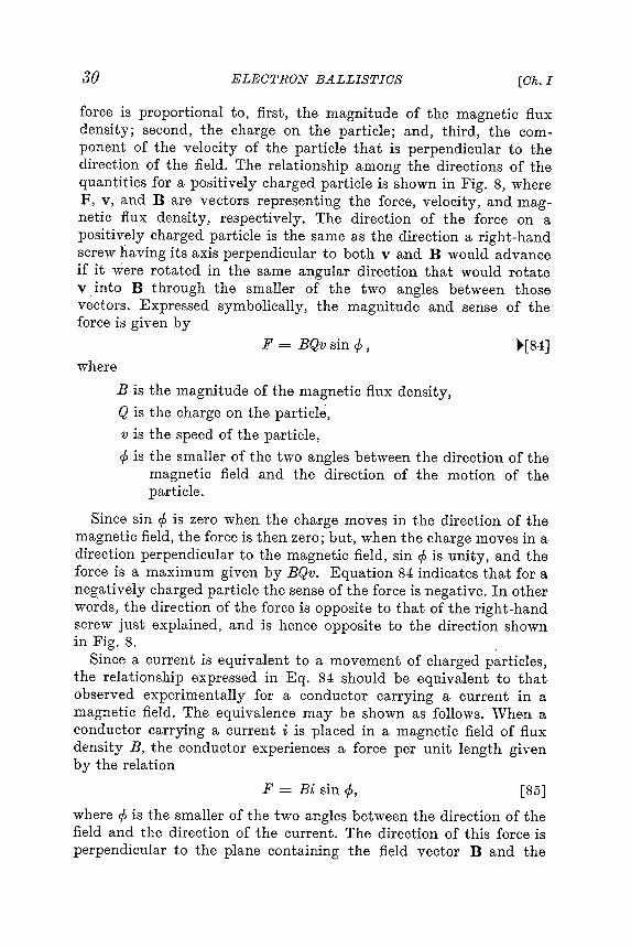
30 ELECTRON BALLISTICS [Ck. I
force is proportional to , first , the magnitude of the magnetic fluxdensity ; second, the charge on the particle ; and, third , the component
of the velocity of the particle that is perpendicular to the
direction of the field . The relationship among the directions of thequantities for a positively charged particle is shown in Fig . 8, whereF , v , and B are vectors representing the force, velocity , and magnetic
flux density , respectively . The direction of the force on a
positively charged particle is the same as the direction a right -handscrew having its axis perpendicular to both v and B would advanceif it were rotated in the same angular direction that "\vould rotatev into B through the smaller of the two angles between thosevectors . Expressed symbolically , the magnitude and sense of theforce is giv~en by
F = BQv sin <I> , :"[84]where
B is the magnitude of the magnetic flux density ,Q is the charge on the particle,
. v is the speed of the particle ,
<I> is the smaller of the two angles between the direction of themagnetic field and the direction of the motion of theparticle .
Since sin ~ is zero when the charge moves in the direction of themagnetic field , the force is then zero; but , when the charge moves in adirection perpendicular to the magnetic field , sin ~ is unity , and theforce is a maximum given by BQv. Equation 84 indicates that for anegatively charged particle the sense of the force is negative . In otherwords , the direction of the force is opposite to that of the right -handscrew just explained , and is hence opposite to the direction shownin Fig . 8.
Since a current is equiv~alent to a movement of charged particles ,the relationship expressed in Eq . 84 should be equivalent to thatobserved experimentally for a conductor carrying a current in amagnetic field . The equivalence may beshov ,,-n as follows . When aconductor carrying a current i is placed in a magnetic field of fluxdensity B , the conductor experiences a force per unit length giv~enby the relation
F = Bi sin </>, [85]
where c!> is the smaller of the two angles between the direction of thefield and the direction of the current . The direction of this force is
perpendicular to the plane containing the field vector B and the

31Art . 7] .L'f O T I ON IN MAGNETOSTATIO FIELDS
[86]where
a gIven cross
conductor . This relationship is also illustrated by Fig . 8 . An electric
current in a conductor of small , l1niform cross section is equivalent to
a stream of electric charges moving along the path of the current , all
with the same speed , and is given by
i = Qnv ,
Q is the charge on each particle ,
n i 's the number of charged particles per unit length of the
path of i ,
v is the speed of the particles ,
nv is the number of charged particles that pass
section of the path of i per unit time .
F
y
B
90
/ . x
_ i - Qvor 1
..-..-
..-
Fig . 8 . Direction of the force Fig . 9 . Rectangu -
exerted by a magnetic field on Jar co - ordinate
a current or a positively charged system for Eqs .
moving particle . 92 , 93 , and 94 .
The substitution of i from Eq . 86 in Eq . 85 gives
F = BQnv sin </ > [ 87 ]
for the force on a unit length of conductor , or the force on n particles .
Since there is no reason why the force on one particle should be greater
than that on another , the force on one particle is given by division of
Eq . 87 by n ; whence ,
F = BQv sin </ > [ 88 ]
. for one particle , 21 a .n expression identical with Eq . 84 .
21 This derivation of Eq . 88 from the equation for the force on a current - carrying conductor
applies only to the force on a single charged particle moving as a part of a uniform
stream of charged particles . For a discussion of the force on a single moving charge , see
W . R . Smythe , Static and Dynamic Electricity ( 2nd ed . ; New York : McGra \ v - Hill Book
Company , Inc . , 1950 ) , 565 - 567 and 574 - 576 .

22 For an introduction to the cross-product notation , see N . H . Frank , Introduction toElectricity and Optics (2nd ed.; Xe\v York : McGraw-Hill Book Company, Inc ., 1950),107- 108.
* Current is ordinarily defined as a scalar quantity , and current density as a vector .Since the current considered here is supposed to be analogous to a stream of chargedparticles , the current -density vector associated \vith the current crossing a given crosssection of path is directed along the path at every point on the cross section, and it istherefore possible to define the vector i \vhose magnitude is the current , and whosedirection is that of the current path .
32 ELECTRON BALLISTICS COho I
In the notation of v"ector analysis ,22 the vector force F as given byEq . 84 is
F = Q(v X B ), [89]
and as given by Eq . 85 is * . [ 90]F = 1 X B .
As a result of the force, acceleration of the charged particle takes place,and .
F = ma = Q(v X B ). [91]
In the rectangular co-ordinate system of Fig . 9, Eq . 91 becomes theset of three differential equations
d!.!: = 2-[B ~ - B ~] ~[92]dt2 m Z dt y dt '
~ = 2-[B ~ - B ~] ~[93]dt2 ')11, x dt Z dt '
~ = 2-[B ~ - B ~] '-[94]dt2 mY dt x dt '
where Bx, By, and Bz are the components of the magnetic fluxdensity along the corresponding three co-ordinate axes . These equations
are readily derived from the fact that , when the direction of
motion of the charge is perpendicular to the direction of the magneticfield , the force is given by BQv and is perpendicular to these twodirections as shown in Fig . 8. The foregoing equations hold in anyconsistent system of units . For example , in the mks system the forceis given in newtons when Q is in coulombs , B is in webers per squaremeter , v is in meters per second , and x , y , and z are in meters .
An electric field exerts a force on a charged particle whether the particle is at rest or in motion , and the force is always in the direction of
the field . On the other hand , according to Eq . 84 or Eq . 89, a magneticfield exerts a force on a charged particle only if the particle is inmotion and the direction of the motion is not parallel to the directionof the field . If a force does act on a particle because of a magnetic field ,

the force is perpendicular to the field . Since the force is also perpendicular
to the direction of motion of the particle , a magnetic field can
do no work on the particle . Thus it is not possible for a magnetic field
to change either the kinetic energy or the speed of a charged particle .
A magnetic field is capable of changing only the direction of motion
of the particle .
In the remainder of this article , the equation for the force on a
moving charged particle in a ma .gnetic field , Eq . 84 or Eq . 89 , together
with the . concept that a magnetic field can change the direction but
not the magnitude of the velocity
of a charged particle , is applied to
determine the path of a charged
particle in a uniform magnetic field
for different initial - veloc ~ ty conditions
.
7a .
path
In this equation v is a constant speed unchanged by the magneticfield , and Q and m are constants . If , further , the magnetic flux
33Art. 7] _i110 T I ON IN l1f A G NE TO ST A T I O FIELDS
Boundary~I UniformField - free -J.-magneto static -+- space : field. Bx
x
x
x
x
x
x
x
x
x
x
x
xx
mv._- .1 - BQ [97]
Circular Path . In Fig . l Oacharged particle , assumed to be anelectron , is projected into a mag-netostatic field having a directionperpendicular to the paper anddirected into it . The force exerted
by the field is always perpendicular
to tl :e direction of motion , and the Fig. 10. Circular path of an elec-partIcle therefore follows a curved tron that enters perpendicularlypath . The force producing the curva - into a magneto static field.ture is
F = BQv , ~[95]
where v is the speed of the particle at any point . The accelerationcaused by this force is , from kinematics , v2Jr, where r is the radius ofcur ,"ature of the path . By Newton 's second law ,
mv2F = ma = BQv = - ; [96]
r
whence ,
density B is uniform everywhere along the path , the radius is thenconstant and the path is a circle .
If the particle acquires its speed v from motion through an accelerating electrostatic field of potential difference E , as is indicated in

34 ELECTRON BALLISTICS
"[99]
ECho I
relation Fig : 10, the speed is given by Eq . 30, and substitution of thisin Eq ~ 97 giv.es
1J mr = B - 2 Q E . [98]
In Eq . 98, Q is negative if the particle carries a negative charge.Thus if the particle is an electron , the value of Qe/me from Eq . 3 maybe placed in Eq . 98, and the expression for r becomes
J1 2E
r = B 1.76 X 10¹¹
VE= 3.37 X 10- 6 B meters,
where E is in volts and B is in webers per square meter .
The relation given in Eq . 98 may be applied for the experimentalmeasurement23 of the ratio Q/m for electrons or ions . A beam ofcharged particles produced by a " gun" in the form of a filament andpierced anode , or by some other suitable source , is directed into a ring -shaped tube properly arranged in the magnetic field of Helmholtz coilsso that the beam is bent in a circle along the axis of the tube . To determine
the path of the beam, the charge that impinges on a collector
electrode located in the tube at a fixed distance away from the source
of the particles may be measured , sufficient gas may be left in thetube to render the path visible through excitation of the gas, or thebeam may be allowed to fall on a fluorescent or photographic plate .The measurements of rE , and B constitute data for the calculation
of Q/m. The magnetic field of the earth may contribute to the bendingof the beam, and this possibility must be taken into account in the calculation
unless experimental precautions are taken to counteract it .
The principle that the radius depends on the mass-to -charge ratioof the particle as indicated by Eq . 98 has been applied in a devicecalled a mass spectrometer for the identification and separation ofparticles having different values of this ratio . In this apparatus a beamcomposed of a mixture of ions having different ratios of mass tocharge separates along paths of different radii when it passes througha magnetic field . The particle having the desired ratio is then collectedon an electrode at the terminus of its path .
Isotopes , which are atoms that have different masses but identicalchemical properties and are therefore different forms of the same
23 A . J . Dempster , " Positive -Ray Analysis of Potassium , Calcium , and Zinc ," Phys .Rev ., 20 (1922 ), 631 - 638 ; F . W . Aston , irlass Spectra and Isotopes (2nd ed . ; London :Ed \vard Arnold & Co ., 1942 ) .

35MOTION IN .i11 A G NE TO ST A T I G FIELDSArt . 7]
chemical element , were first discovered and identified by use of a mass
spectrometer . Separation of natural uranium to obtain the isotopeuranium 235 was first accomplished in quantity by application of the
same principle .24.The mass spectrometer also finds wide industrial use as a means for
locating leaks in vacuum systems .25 The device is connected to theevacuated system so as to sample the gas in it while a small jet ofrare gas such as helium is passed over the outside surface . Presence
Fig . 11. l\Iagnetic deflection of the beam in a cathode -ray tube .
of that particular gas in the mass-spectrometer indication shows thatthe leak has been reached by the jet .
7b. Magnetic Deflection in a Cathode-Ray Tube. A magnetic fieldis frequently used as a means of deflecting the electron beam in acathode-ray tube . Usually the magnetic field is produced by the instantaneous
current in a pair of coils located near the electron gunand oriented so as to direct the field perpendicular to the electronpath , as is illustrated in Fig . 11.
If at any instant the field is uniform between the boundaries indicated and remains constant while the electrons pass through it , the
beam , which enters the field at A , is deflected to B along a circular.path , having a radius r . Thereafter it continues along a straight path
24 H . D . Smyth , Atomic Energy for Military Purposes (Princeton , N .J . : PrincetonUni \ 'ersity Press , 1947 ), 187- 205 . J . H . Pomeroy , " Electromagnetic l\Iethods of Separating
Isotopes ," The Science and Engineering of1:'l"uclear Pou 'er, Vol . II , Clark Goodman ,;Editor (Cambridge , Mass . : Addison -\ Vesley Press , Inc ., 1948 ), Appendix A -2, 301 - 306 .
25 A-\.. O . Kier , C. M . Stevens , A . Hustrulid , and T . A . Aqbot , " Mass Spectrometer for
Leak Detection ," J . App . Phys ., 18 (1947 ), 30- 48 .

to produce a spot on the screen at the deflected positionS . The circularpath AB sub tends an angle () at C. The triangle SOR formed by thescreen, the undeflected path , and the deflected path projected backward
to 0 is similar to the triangle BCD because their respectivesides are perpendicular . Hence, the angle at 0 is also 0, and
Substitution for r from Eq . 98 wi~h the values of Q and m for an
~. . . - . . . . . . . . rn
co
t- ~
i : j H
< . . . . . . ~
~
p . . , " " " : : ; 1
~
ro
p - ~
0 " 0 P
. . . . . . i : j 0 ~
( D
i : j P ' "
<
0 " ' - 1 rn
~
( D
ro
cot
- ~
. . , . . ~ . cot
- ~
~
0 i : j ~
( D
5" g ? 6 : ~ ~ ~ ( D ( D ~ gi
g
: g . " ~ ~ ~
~co
t- ~ oO " ' ro ~ : > 1 ~ ~
( Di
: j CD
~ ~ cot
-
.. . . . . co
t- ' - ~
~
0 co
t- ~
0 . . . . . ~
ro
~
( D
~
~
4
p - ~
P
~
~
~
? t . 9 ~
~ . ~
. . . . . . g . &
t : ! j i : j 0 -
(D
. , . . . . . . . . . . . i : j " ' " . . . . . . ~
, . . . . " " " ' ; S
co
t- p - ~
( D . . . . .
~
~
~
~
p . . , g ~
~
. . . . . . ~
~
cot
- " 0 ~
( D
~
0 roO
~
rn
( D
~
p - . , ) . ~
i : j ~
~( D
ccot
- ~ . , . . . . . o ~ cot
- p . . , p . . , ~
~ p . . , rn &
0" ~
~ ~
s . ; ~ . . . . . . . ~ . co
t- ~
~
~
e - : ~ I ~
~
~
p . . , ~
i: j ( D
( D
rn
ro
9 cot
- . . . . ( D
~
aq
0 - ~
p . . , . . . . . . ( D
aq
~
p . . , . . . . . . . ~
p - " ' " ~
~
P " " H ' i : j : : : b ~
~
0 t : ! j . 10 , . . ( i : j &
( D
~
Z - . t - d ~
~
P
cot
- ( D
~
I- I ' ) ~
1 - ioIp
. . , ( D
~ o ~
0 ~
~ ~ o
~
~
' : ~
p . . , g ~ . i : j : = : ' g ~
~
8 g : ~
&~ ~
~ i : jO " ' i : jroo
~ . . . . . . ~ ( D
~
i : j ~
.. . . . . . c ( D , . . . . ~
. , . + - &
. , . . ( D
, . . , &
cot
- " " I
.. . . . < . . . ; , ~
& . . . . . ( D
, ; . . . 1 - 1 ' ) co
t- ~
~
. , . . . . 0 . . . . . . . , . .
., . . . . . . . . . . . . . V
J 0 co
t-
0 ~
~
. . . . . ( D
~
P ' &
0 ~
. . . . ro
, . . . .
&
. . . . . , . . . . . &
. . cot
- i : j
1- 1 ' ) ~
~
0 " ' c . . 0 i : j p - i : j " " ' . ( D
p . . , p - p . . , " ' " '
~
~
~
( D
1 - 1 ' ) &
( D
ro
i : j ~
( D
CD
: : : ; ' V " I
P' ( D
~
0 0 H
~
. aq
ro : : : b . . . . . . ( D
~I ~
~
0 ~
1 - 1 ' ) ~
i : j g . ( D
g ' <
g i : j 0 a
Q) ~ I - I ' ) ~ ~ ~ ( D ~ ~
o ~
&
rn ~ . . . . . .
II
ro . . . . . . ~
9 ~
i : j ~
9 : ; : t : ' 9 o ' C ; ; ~
~
o' ij ; ~
oc + ~ ~ ( D
~ ~
i : j i : j ~ aq
~I ~
1 - 1 ' ) ( " ) ~
~
~ aq
c +
aqaq
~
. , . + - ~
( D
.
~
~
~
( D
( D
~
p . . , 0 p - ~
i : j c +
~
0 . . . . . .
~
&
; : - 5 ( D
~
~
5 ' c ; . ? t - ~
( D
~
i : j
-- " p - 0 - . . : > 1 P
0 ~
aq
~
H
, . . . . 0 ~
&
-- . . _ ~
~ ~ . , . + - i : j cot
- ~
rn
~ cot
-
~
0 ~
? t . aq
O ' p . . , g ' ~
& ; . p . . , ( D
rn
o ' ~
~
1 - 1 ' ) . i : j ~
~
( D
~
~
i : j
~
~
( D
( D
. . . . . . g . ~ . . . . . . ~ : : : b " ' " ~
~
( D
(D
1 - 3 ~
Z - . ~
( D
~
~
~
( D
z - . ~ . . . . . . ro
~
~
p - ' U
0 . . . . . . . rn
aq
, . . , ~
<
~
c +
0
"" I " " ~ ' U
( D
" " " ' & , . . . . ( Do
" ' + -
.. . . . . . , . . ' - " ( D
~
~
p . . , ( D
( D " " " cot
- i : j ~
rn~
rn " " . . . . . . , . . . . c +
o ~ . . . . . 0
&
ro
' - " , . . . . rn
p - ~
: > 1 i : j - . . . . . . . ' &
O' ~
o ' p : : ~
&
( D
i : j cot
- , . . . . " " " . . . . . . p - i : j
.. . . . . ~
~
aq
( D
rn
ro
i : j ( D
(D
aq
i : j p . . " . . . . i : j ~ . . . . . . i : j " " I . . . . . . 9 ~
~
&
OO
O
( D
ro . , . . i : j &
~
9" " " p - ~
i : j ( D
, . . . . rn
, . . . . p . . , <
p - ~
i : j
0 ~
P ' rn ~
' g . ~
~
~
( D
( Daq
'
~. i : j i : j p - ~
a ( D
~
i : j ' ri3
8 ~
1 - 3
~<
~ oo
~
. . . . . . " ' + - ~
" " " " + - P -
aq
~
. . 0 cot
- ~
. . . . . . & ; . ~ . i : j ~
~
W " , . . . . ~
r- - 1 O . . . . . . . . ( D
rn
. . . . . ~
aq
0 ro
-
~
, . . , - - " , , - ( D
&
( D
~
. , . + - - -
0
. . . . . . , 9 . - ~
( t : i : j P - rn
~
0 ~
P - ' ; : ; - ' &
W
" ' + - c : " t " o < ~ o ( t >
( t > ~
0 ~ " " P ' "
L- - ' P " ' ~
~ ( t > ~
cot
- i : j ~
I ro
I cot
- X
( D
36 ELECTRONBALLISTICS [Ch. I
ds l- -SO - ; . [100]
For small values of (), point 0 lies at the center of l as is indicated onthe diagram , and SO is approximately equal to ls, the distance fromthe center point to the screen. When the deflection is small , therefore ,its value as given by Eq . 100 is
d - Uss - -
r .[101]
M~gnetic deflection sensitivity = j = Us V Qd(2-;nJ ~ ' [102].v Eb
electron gives
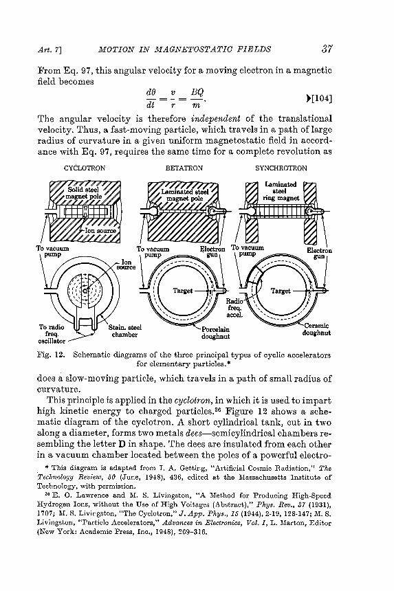
37Art. 7] MOTION IN lJ;fAG NE TO ST ATIO FIELDS
From Eq . 97, this angular velocity for a moving electron in a magneticfield becomes
~ = ~ = !!.2. :"[104]dt r m
The angular velocity is therefore independent of the translationalvelocity . Thus , a fast -moving particle , which travels in a path of largeradius of curvature in a given uniform magneto static field inaccordance
with Eq . 97, requires the same time for a complete revolution as
CYCLOTRON BETATRON SYNCHROTRON
Fig . 12. Schematic diagrams of the three principal types of cyclic acceleratorsfor elementary particles ..
does a slow -moving particle , which travels in a path of small radius ofcurvature .
This principle is applied in the cyclotron , in which it is used to imparthigh kinetic energy to charged particles .26 Figure 12 shows a schematic
diagram of the cyclotron . A short cylindrical tank , cut in twoalong a diameter , forms two metals dees- semicylindrical chambers resembling
the letterD in shape. The dees are insulated from each other
in a vacuum chamber located between the poles of a powerful electro -
. * This diagram is adapted from I . A . Getting , " Artificial Cosmic Radiation ," TheTechnology Review , 50 (June , 1948 ), 436 , edited at the Massachusetts Institute ofTechnology , with permission .
26 E . O. Lawrence and l \I . S. Livingston , " A Method for Producing High -SpeedHydrogen Ions , without the Use of High Voltages (Abstract )," Phys . Rev ., 37 (1931 ),1707 ; l \I . S. Livingston , " The Cyclotron ," J . App . Phys ., 15 ( 1944), 2-19, 128-147; MS .Livingston , " Particle Accelerators ," Advances in Electronics , Vol . I , L . Marton , Editor(New York : Academic Press , Inc ., 1948 ), 269 - 316 .

38 ELECTRONBALLISTICS [Ok. I
magnet weighing many tons in most cyclotrons , and the direction ofthe magnetic field is perpendicular to the semicircular faces of the dees.A high -frequency oscillator is connected to the dees, and a source ofcharged particles such as protons or deuterons is provided near theircenter as shown on the diagram . When a charged particle leaves thesource it is accelerated into the dees in one direction or the other bythe electric field set up by the oscillator . Inside the dees, the electricfield is small , because it is concentrated mainly across the gap , andthe ch"arged particle travels in a circular path at constant speed underthe influence of the magnetic field . The frequency of the oscillator andthe magnetic field strength are so adjusted that , when the chargedparticle again reaches the gap , the electric field has reversed . The electric
field therefore gives the charged particle a second acceleration
across the gap , adding to its speed . The charged particle then travelsa path of larger radius through the opposite dee, but reaches the gapafter the same time interval . During this interval the electric field hasagain reversed and is in a direction to accelerate the particle further .This process is repeated many times until finally the charged particletravels in a path near the periphery of the dee. As long as the speedof the particle remains so low that the mass stays essentially constant ,a fixed -frequency oscillator can be used because the time of a revolution
is constant . Subjected to a hundred or more revolutions with an
increase in speed corresponding to several thousand volts twice eachrevolution , the particles can be given energies corresponding to severalmillion volts , yet the voltage of the source need be only a few thousandvolts . The particles are finally led off through a side tube to a targetfor experimental purposes , such as the nuclear disintegration ofelements .
When the speed of the particles such as protons in a cyclotronexceeds that corresponding to energies of 10 or 20 million electronvolts , the mass increases appreciably , and the angular velocity decreases
as the energy increases . An equilibrium is reached at which
the particles cross the gaps at essentially the instants of reversal ofthe electric field . The particles then receive no further energy fromthe field and hence travel in a path of constant radius . If the frequencyis then decreased , however , the radius and the mass continue toincrease in such a manner as to maintain the equilibrium . A cyclotronwith such a changing frequency is called a frequency -modulatedcyclotron or synchr Q"cyclotron .27 It has produced particles havingenergies of 400 million electron volts .
27 WM . Brobecl~, E. O. Lawrence, K . R. MacKenzie, E. l\I. Mc:.lillan , R. Serber,D. C. Sewell, K . 1\1. Simpson, and R. L. Thornton, " Initial Performance of the 184-inchCyclotron of the University of California," Phys. Rev., 71 (1947), 449-450.

Art. 7] J.WOTION IN J.IAGNETOSTATIO FIELDS 39
Magnetic induction , rather than a radio -frequency electric field , isused for accelerating electrons in a device also illustrated in Fig . 12called a betatron.28 A changing magnetic flux in it induces a uniformelectromotive force tangentially along a circular path for the electrons ,and accelerates them to high energies. The electrons are held in anorbit of fixed radius by a second changing magnetic field located atthe orbit but perpendicular to it . The flux density of the second fieldis maintained equal to one-half the average flux density inside theorbit . An .evacuated annular chamber in the shape of a hollow doughnut
surrounds the circular path . The magnetic flux for inducing the
electromotive force along the path is produced in a laminated steelelectromagnet by an alternating or pulsed power source, and thesecond magnetic field for guiding the electrons is produced in an airgap in the same or a different electromagnet excited by the ~amesource . Bunches of electrons released in the chamber in synchronismwith the supply travel many times around the chamber , and gain afew hundred electron volts of energy e.ach time around . Finally themagnetic field is suddenly altered so as to cause the electrons toemerge with energies of more than 100 million electron volts .
The synchrotron29 shown in Fig . 12 is a particle accelerator thatutilizes some of the principles of both the cyclotron and the betatron .For accelerating electrons, the machine first acts as a betatron whileimparting an initial energy to the electrons. After they reach energiesof a few million electron volts , so that their . speed is near that of light ,additional energy is given them by a radio -frequency electric fieldexisting between electrodes situated along their path in the doughnut -shaped chamber . The frequency of the electric field can be constantbecause the electrons continue to travel at essentially the speed oflight despite further increase in energy. Thus their angular velocityaround the center of their orbit is essentially constant . The guidingmagnetic field at their orbit must continue to increase in proportionto their mass , however . Increase of the magnetic field inside the orbitis no longer necessary once the betatron action is complete , hence thesteel inside the orbit may be allowed to saturate magnetically . Theweight and cost of the machine may therefore be reduced below thecorresponding values for a betatron . Electron energies of more than300 million electron volts are produced by electron synchrotrons .
28 D . W . Kerst , " The Acceleration of Electrons by Magnetic Induction ," Phys . Rev .,10 (1941 ), 47 - 53 ; E . E . Charlton and W . F . \ Vestendorf , " A 100-Million Volt Induction
Electron Accelerator ," J . App . Phys ., 16 (1945 ), 581 - 593 .
29 V . Veksler , " A Ne \v Method of Acceleration of Relativistic Particles ," J . Phys .U .SiS .R ., 9 (1945 ), 153 - 158 ; E . 1\1. McMillan , " The Synchrotron - A Proposed HighEnergy Particle Accelerator ," Phys . Rev ., 68 (1945 ), 143- 144 ; EM. 1\Ic Milian , " TheOrigin of the Synchrotron ," Phys . Rev ., 69 (1946 ), 534 .
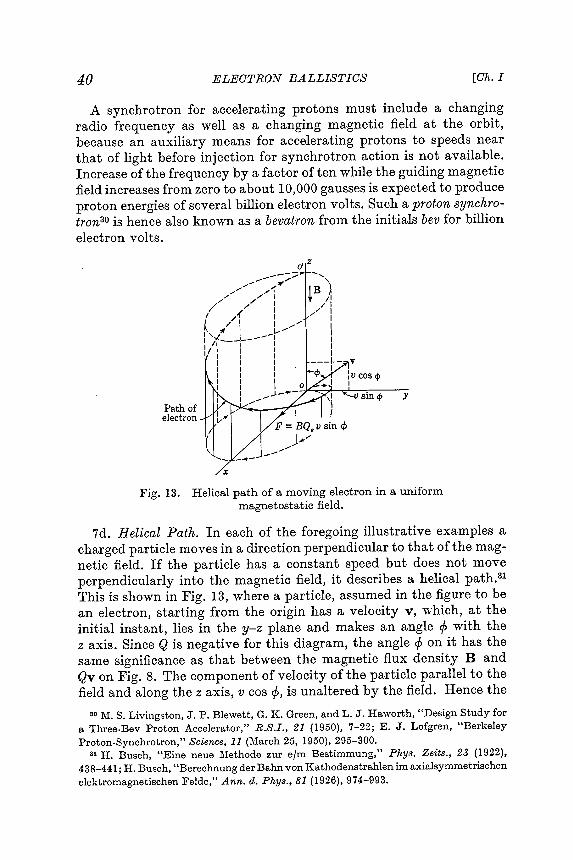
[Ch. I40 ELECTRONBALLISTICS
Proton-Synchrotron," Science, 11 (March 25, 1950), 295- 300.31 H. Busch, "Eine neue Methode zur elm Bestimmung," Phys. Zeits., 23 (1922),
438-441; H. Busch, " Berechnung der Bahn yon Kathodenstrahlen im axialsymmetrischenelektromagnetischen Felde," Ann. d. Phys., 81 (1926), 974- 993.
A synchrotron for accelerating protons must inclpde a changing
radio frequency as well as a changing magnetic field at the orbit ,
because an auxiliary means for accelerating protons to speeds near
that of light before injection for synchrotron action is not available .
Increase of the frequency by a factor of ten while the guiding magnetic
field increases from zero to about 10 , 000 gausses is expected to produce
proton energies of several billion electron volts . Such a proton synchro -
tron3O is hence also known as abevatron from the initials bev for billion
electron volts .
dZ
- - / - ,- - . . . . ' \
" " , , - - 1 " " " IB )
/ ' " / / I t / II" .. . . I /
/ / . . .. I / / I. ( I 1
/ / 1 I " , ' " 1
I / I L. . . " " I
~ ~ I - - I I
I ' " ' - _ - J - - - I I
I / 1 I I II I I I I
I I I I - - - t - -
I I I
I I I 4 > cos 4 >
I : I 0 . 1
I II . . .1 - . - - I V sin 4 > y
- ' 11 " , -
Path of !
electron F = BQe v sin <t >
J . - - "' "
.. . .- -
Fig . 13 . Helical path of a moving electron in a uniform
magneto static field .
7d . Helical Path . In each of the foregoing illustrative examples a
charged particle moves in a direction perpendicular to that of the magnetic
field . If the particle has a constant speed but does not move
perpendicularly into the magnetic field , it describes a helical path . 31
This is shown in Fig . 13 , where a particle , assumed in the figure to be
an electron , starting from the origin has a velocity v , which , at the
initial instant , lies in the y - z plane and makes an angle </ > with the
z axis . Since Q is negative for this diagram , the angle </ > on it has the
same significance as that between the magnetic flux density Band
Qv on Fig . 8 . The component of velocity of the particle parallel to the
field and along the z axis , v cas </ > , is unaltered by the field . Hence the
30 MS . Livingston , J . P . Ble \ vett , G . K . Green , and L . J . Ha \ \ ' orth , " Design Study for
a Three - Bev Proton Accelerator , " R . S . I . , 21 ( 1950 ) , 7 - 22 ; E . J . Lofgren , " Berkeley

particle continues to move in the direction of the z aXIS with a speedv cos cp. However , the velocity component v sin cp gives rise to a forceon the particle , and , although the magnitude of this componentremains constant , its direction is altered continuously . By Eq . 97, theprojection of the path in the x- y plane is a circle whose radius is
mvsm
BQ
The superposition of the uniform circular motion in the plane normalto B and the uniform translational motion parallel to B is the condition
for a helical path . The vertical distance covered in one revolution is the pitch of the helix , which is given by
~[l O7]
Art. 7] Jl.fOTION IN .Llf A G NE TO ST A TIC FIELDS 41
<I> ~[l O5]f =
The time of one revolution of the projection is
21Tr 21Tmt - - -0 - v sin <I> - BQ. [106]
Electron gun B - Screen/------------------ --- ------------ --, - ---- --- -I .." -- -- -~€ ~~ ====== == ======== ~~~:3~--- ---------------- .
- IIII +<b) End view of paths
(a) Side vie\v of paths
Fig. 14. Focusing by a longitudinal magnetic field.
Pitch = tov cos </> = 21T'mv COS </>BQ .
7e. lrfagnetic Focusing. The helical paths described above are sometimes utilized for focusing cathode-ray tubes and high -voltage xray
tubes, and are typical of the trajectories in some magnetic electronlenses.32 Figure 14 shows the method of focusing a divergent beam ofelectrons produced by an electron gun . The divergent electrons in the.beam are made to follow helical paths by the magnetic field directedalong the axis of the tube . The electrons follow paths whose projections
on a plane perpendicular to the axis of the tube are circles
32 V. K. Zworykin and G. A. Morton, Television (New York: John Wiley & Sons,Inc., 1940), 117-120; C. J. Davisson and C. J. Calbick, "Electron Lenses," Phys. Rev., 38(1931), 585; and 42 (1932), 580.

42 ELECTRONBALLISTICS [Ok. I
that pass through the axis , as is shown in Fig . 14b . The time of a
revolution is independent of the angle of divergence , and , if this angle
is small enough for its cosine to be essentially unity , all the electrons
have the same translational velocity parallel to the axis of the tube .
Thus all the electrons are at the same phase of their revolution at
any distance from the source . B } T adjustment of the magnetic field ,
which may be produced by a solenoid , all the electrons can be allowed
to complete one or any integral number of revolutions during their
trav ?e~ down the tube , and they then focus at the screen .
8 . l \ IOTION OF CHARGED PARTICLES IN CONCURRENT ELECTRO -
STATIC AND l\IAGNETOSTATIC FIELDS
"\Vhen electrostatic and magneto static fields simultaneously influence the motion of charged particles , the net force on the particle
is the sum of the electrostatic and magneto static forces which would
appear if each field acted independently . Both forces may be represented as "Tector quantities ; hence , in vector notation , the net force is
F = Q [ g + ( v X B ) ] = ma , [ 108 ]
this expression being the sum of Eqs . 9 and 89 . On resolution of the
vectors into components along the axes of the rectangular co -ordinate
system of Fig . 9 , Eq . 108 becomes the set of three equations :
d2X Q [ dy dZ ]dt2 = m <3x + Bz at - BYat ' " [ 109 ]
d2y Q [ dz dX ]dt2 = m 6y + Bxdt - Bzdt ' " [ 110 ]
~ - Q [ dx dY ]dt2 - m <3z + By at - Bx at . " [ 111 ]
These equations completely describe the motion of a particle in combined electrostatic and magneto static fields . Their solution , however ,
is a simple one only when special field configurations having symmetryare involved .
Since , as is shown in Art . 7 , the component of force on a moving
charged particle caused by a magnetic field is always perpendicular to
the direction of motion , the magnetic field cannot alter the kinetic
energy of the particle . If a charged particle moves in a combined
electrostatic and magneto static field , the changes in its kinetic energy

and speed are the result of the electric field alone, and Eqs. 29 and30 are applicable just as though the magnetic field were not present .The paths in concurrent fields are not , in general, circles, since thespeed of a particle is altered as the particle moves through the electricfield . A discussion of several important examples of such motionfollows .
8a. Motion in Parallel Fields . Perhaps the simplest example ofmotion in combined fields occurs when the fields are parallel . A particleliberated . with zero velocity is then accelerated along the electricfield , but experiences no force from the magnetic field , because theparticle has no velocity component perpendicular to that field . This
43Art. 8] MOTION IN CONCURRENT FIELDS
Fig. 15. Arrangement for mea.~urement of particle velocity.
~ B into the page ----.---------Q x x x x x -----------~-------~ =~===~~~~~---------------.----------x x x x x --------1- -----.1- --------situation also holds if the particle has an initial velocity parallel tothe direction of the fields, but not if the initial velocity has acom -ponent perpendicular to them .
If the particle has an initial velocity component perpendicular tothe parallel fields, the path that results is a " helix " whose pitchchanges with time as the particle is accelerated in the direction of theelectric field . The diameter of the " helix ," however , is constant ,because neither of the fields can contribute energy to the componentof velocity perpendicular to them .
Sb. Measurement of Particle Velocity. When the electric and magnetic fields are perpendicular to each other , sev Teralusefluforms of
trajectory arise. One of these forms occurs when particles (for example ,the electrons jn the beam of a cathode-ray tube ) are deflected simultaneousy
by both fields. In Fig . 15 a stream of particles having avelocity venters the evacuated region between the parallel deflectionplates in a direction parallel to the plane of the plates . A uniform"electric field intensity 6 and a uniform magnetic flux density Bare produced in the region between the plates , and are so oriented thatthey tend to deflect the beam in opposite directions ; that is, the directions
of v , B , and 6 are mutually perpendicular . If the magnitudesof the fields are so adjusted that the forces they exert on the particles- -are equal, the particles pass through the region without deflection
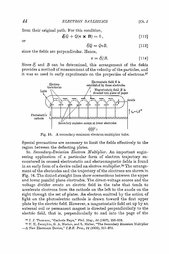
L '
node
i . . ~Ni I ?'N= ?' jUPhotoelectric t
cathode
Secondary emission occurs at lower electrodes
lilli' JA secondary -emission electron -multiplier tube .
Electrostatic field g isestablished by these electrode!;
Magneto static field B isdirected - plane of paper
Fig. 16.
Electrontraiectories
44 ELECTRO::f BALLISTICS ECho I
from their original path. For this condition,gQ + Q(v X B) = 0 , [112]
orGQ = QvB, [113]
since the fields are perpendicular. Hence,
v = G/B. [114]
Since <3 and B can be determined, this arrangement of the fieldsprovides a method of measurement of the velocity of the particles, andit ,,,-as so used in early experiments on the properties of e Jectrons.3'l
Special precautions are necessary to limit the fields effectively to theregion between the deflecting plates .
8c. Secondary - Emission Electron Multiplier . An im portant engineering application of a particular form of electron trajectoryen -
countered in crossed electrostatic and electromagnetic fields is foundin an early form of a device called an electron multiplier .34 The arrangement
of the electrodes and the trajectory of the electrons are shown in
Fig . 16. The dotted straight lines sho,v connections between the upperand lo \ver parallel plane electrodes . The direct -voltage source and thevoltage divider create an electric field in the tube that tends toaccelerate electrons from the cathode on the left to the anode on the
right through the set of plates . An electron emitted by the action oflight on the photoelectric cathode is drawn toward the first upperplate by the electric field . Ho \vever , a magneto static field set up by anexternal coil or permanent magnet is directed perpendicularly to theelectric field , that is , perpendicularly to and into the page of the
33 J. J. Thomson, " Cathode Rays," Phil . .illag., 44 (1897), 293- 316.34 V. K . Zworykin, G. A. Morton, and L. Malter, "The Secondary Emission Multiplier
- A ~e\v Electronic Device," I .R.E. Proc., 24 (1936), 351-375.

Art . 8] Jl,10TIO...V IN COiL\'-CURRENT FIELDS 45
diagram . The path of the electron is therefore bent until it hits thesecond lower plate . This plate and all the other lower horizontalplates have specially prepared surfaces so that , when one electronstrikes them with considerable velocity , several electrons are emittedby the process of secondary emission discussed in Art . 12, Ch. II .These secondary electrons start toward the second upper plate , buttheir paths also are bent by the magnetic field , and they strike thethird lower plate , where each causes the emission of several secondaryelectrons ." This process is repeated in several similar stages down thelength of the tube , the number of electrons in the path increasing ineach stage until finally the stream of electrons is made to strike theanode and is led to the external circuit . If the ratio of the number of
secondary electrons that leave a plate to the number of primary onesthat strike it is b, and if the device has ]\T stages , the current at theanode is bN times the current tha .t leaves the photoelectric cathode .The current is thereby multiplied in the
tube. By this means very sensitive photo- Yelectric devices can be constructed. B2 md\1} 2E
The electric field in the electrode configu- Z iL ~~ration of Fig. 16 is not uniform in magni- B t B ""in; dtude or direction ; hence an exact derivation
of the trajectory of an electron is difficult .However , the trajectory is somewhat similarto that for an electron released with zero
initial velocity at the negative electrode of
the parallel-plane configuration of Fig. 17, ~II~where a uniform magnetic flux density BE +exists in a direction perpendicular to that Fig . 17. Cycloidal motionof the electric field . By adjustment of the in crossed fields.magnetic field strength , the electron pathcan be curved to such an extent that the electron does not reach the
positive electrode .The trajectory of the electron in Fig . 17 is conveniently described
by reference to the rectangular co-ordinate axes x, y , and z oriented asshown . Then , if the electrodes are infinite in extent ,
€ x = - Eld , [ 115] '
.where E is the potential of the right -hand electrode with respect to theleft -hand electrode and d is the distance between the electrodes . Also ,
Bz = B , [ 116]
and all other components of the crossed electrostatic and magneto -static fields are zero . Equations 109, 110, and III apply in this coordinate
system , and , upon substitution of the above conditions and

46 ELECTRON BALLISTICS [Ok. I
[117]
[118]
[119]
u = j !!!.- [ 1 (1 - EjB(Q6111~6)t)]Bd B(Qe/me) .* Boldface italic (slanting ) type is used for letters denoting complex numbers.t This solution may be recognized as similar in form to that for the charge in the
problem of an electric circuit containing resistance and inductance in series and subject
the current is
i = ~ = ! (1 - E-<R/L)t)dt R '
q =~ [t - ~ (1 - E-<R/L)t)].and by integration,
to a suddenly applied electromotive fGrce E . Thus , if
L ~ + R ~ = Edt2 dt '
-~ [-~ + B~],me d dt~= -~ [-B~]dt2 me dt '
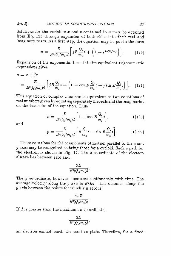
This equation of complex numbers is equivalent to t \VO equations ofreal numbers given by equating separately the reals and the imaginarieson the two sides of the equation . Thus
and
These equations for the components of motion parallel to the x andy axes may be recognized as being those for a cycloid . Such a path forthe electron is shown in Fig . 17. The x co-ordinate of the electronalways lies between zero and
than
47FIELDS
u= E [oBQe ( )]B2(Qe/me)d J ~ t + 1 - EjB(Q./me)t . [126]
Expansion of the exponential term into its equi ,,-alent trigonometricexpressions gi yes
u = x + jy
= B2(~ [ j B ~ t + (1 - cas B ~ t - j sin B ~ t )] . [127]
E [x = B2(Qe/me)d 1 - cas B~ t],
y = E [B Qe Q ]B2(Qe/me)d m t - sin B -! te me
"[128]
~[129]
2E .B2(Qe/me)d
21TE
If disgreater the maximum x co-ordinate ,
2E
an electron cannot reach the positive plate . Therefore , for a fixed
Art . 8] J'tf O T I O.LV IN CO ~!CUR R Ei V T
Solutions for the variables x and y contained in u may be obtained
from Eq . 125 through expansion of both sides into their real and
imaginary parts . As a first step , the equation may be put in the form
.B2(Qe/me)d
B2(Qe/me)d'
The y co - ordinate , however , increases continuously with time . The
average velocity along the y axis is EjBd . The distance along the
y axis between the points for which x is zero is

48 ELECTRON BALLISTICS [Ok. I
separation , a magnetic flux density greater than the critical magneticflux density ,
1
Bo = d V 2Eme/Qe , [ 130]
is sufficient to interrupt the electronic current bet ","een the electrodes .The relation given by Eq . 130 \vas used to measure35 the ratio of
charge to mass of the particles emitted by the photoelectric effect ,which . \vere thus identified as electrons .
Because uniform fields are seldom established with the electrode
configuration of limited size employed in practical electronic devices,the expressions derived above are useful only as a guide to the conditions
for critical control or production of the desired paths , such asthose in the electron multiplier . In the electron multiplier the electricfield is nonuniform , and the arrangement of the electrodes produceslongitudinal as well as transverse components of varying magnitudewith respect to position in the tube .- The path of the electrons in thatdevice therefore only approximately resembles a cycloid .
Most present -day electron multipliers do not require an auxiliarymagnetic field to produce the desired path of the electrons.36 The electrodes
are shaped so that the electrostatic field alone causes theelectrons to impinge upon the electrodes in succession . Figure 28 ofCh. II shows one configuration of electrodes used. Discussion of theoperating characteristics of multiplier phototubes is given in Art . 13,Ch . II .
8d. .il1agnetron. Another practical application of the motion ofelectrons in perpendicular electrostatic and magneto static fields occursin an electron tube called the 111-agnetron.37 Its chief application is as anoscillator to generate high radio -frequency po\ver for such purposes asmicrowave radar .38 In its elementary form the magnet ron consists of a
35 J . J . Thomson , " On the Masses of Ions in Gases at Low Pressures ," Phil . Mag ., 48
( 1899 ), 547 - 567 .36 V . K . Zworyl { in and J . A . Rajchman , " The Electrostatic Electron Multiplier ,"
I .R .E . Proc ., 27 (1939 ), 558 - 566 ; C. C. Larson and H . Sa linger , " Photocelll \IultiplierTubes ," R .S.I ., 11 ( 1940 ), 226 - 229 ; J . S. Allen , " Recent Applications of Electron
l \Iultiplier Tubes ," I .R .E . Proc ., 38 (1950 ), 346 - 358 .37 For early work along these lines , see: H . Gerdien , United States Patent , 1,004 ,012
(September 26 , 1911) ; ..:\.. W . Hull , " The Effect of a Uniform Magnetic Field on the l \Iotionof Electrons bet \\'een Coaxial Cylinders ," Phys . Rev ., 18 (1921 ), 31- 57 ; E . G . Linder ,
" Description and Characteristics of the End -Plate :L\Iagnetron ," I .R .E . Proc ., 29 (1936 ),633 - 653 .
38 G . B . Collins , Editor , ..'tlicrowave .Lllagnetrons , l \Iassachusetts Institute of Technology
Radiation Laboratory Series , Vol . 6 (Ke \v York : McGraw -Hill Bool ~ Company , Inc .,
1948 ); K . R . Spangenberg , Vacuum Tubes (Xe \v York : McGraw -Hill Book Company ,Inc ., 1948).

cylindrical anode and a coaxial cylindrical cathode inside an evacuatedchamber as shown in Fig . 18a. The electrons emitted by the cathodeare attracted to the anode by the radial electric field set up by anexternal source of voltage connected between the anode and cathode .If a sufficiently strong longitudinal magnetic field is impressed parallelto the axis , the paths of the electrons are curved , and they can be prevented
from reaching the anode . The magnetic field is therefore a means
y
. . -
p '
of current control . Furthermore , under certain conditions mentionedsubsequently , the tube may exhibit negative resistance, and themagnet ron may then be employed in conjunction with a resonantcircuit to generate oscillations of a very high frequency .
Electrons that leave the cathode of the magnet ron follow curvedtrajectories such as paths 1, 2, or 3 in Fig . 18bfor decreasing strengthsof the magnetic field . The trajectory 2 corresponds to the conditionthat the electrons graze the anode. For magnetic flux densities greaterthan the critical value that corresponds to trajectory 2, the electronsmiss the anode and are turned back to the filament ; for magnetic fluxdensities smaller than this critical value , all the electrons reach the.anode. A determination of this critical value of magnetic flux density ,denoted by Bo, is therefore of interest .
Art . 8] MOTION IN CONCURRENT 49FIELDS
-x- -
(a) (b)
x
x v =
/
- - L/ " -
/ " -
Y Vt=r ~0 dt
drB Qe dt
(c) (d)
Fig . 18. Electron trajectories in a magnet ron ~
+CbCylindrical anode x",\\\ B\ Axial filament .-I ZIII,,I/ y...

50 ELEGTRO...V BALLISTICS [Ok. I
and a tangential componentd ()
Vt = r dt ' [ 132]
as is shown in Fig . 18c, and the square of the speed of the electron
In the derivation of the relation involving the plate voltage eb, thecritical magnetic flux density Bo, and the dimensions of the tube , itis necessary to make certain simplifying assumptions in order toobtain a solution with reasonable effort . The tube has cylindrical symmetry
, and cylindrical co-ordinates can be used to advantage if the
fringing of the electric field at the ends of the cylinder is considerednegligible . Accordingly , it is assumed that (a) the effect of the fringingof the electric field is negligible , (b ) the electrons are emitted from thecathode with zero initial velocity , (c) the radius of the cathode is smallcompared with the radius of the plate , and (d ) the voltage drop alongthe cathode is small compared with the plate voltage eb. The relationsderived on the basis of these assumptions are found to be in goodagreement with the results of experimental measurement of thecharacteristics of such tubes .
To utilize the cylindrical symmetry , it is convenient to express theposition of an electron between the filament and anode , say at point Pin Fig . 18a, in terms of the radius r and the angle e. The solution isindependent of z, since the fields are oriented so that the electronexperiences no component of force along the z axis . The radius of theplate is denoted by r 2)' and that of the cathode by rk , where rk is smallcompared with r 2). A solution for the trajectory might be obtained byemployment of Eq . 108 in cylindrical - co-ordinate form and substitution
of boundary conditions . However , in the following analysis the
relations are built up as they are needed from fundamental physicalprinciples .
For the critical magnetic flux density , the electron grazes the plate ,and the radial component of its velocity dr Jdt is therefore zero when ris equal to r 2). In order to utilize this important boundary condition ,the first objective of this analysis is to obtain an expression involvingdr Jdt ; and the second objective is to evaluate each term of this expression
for the point on the grazing trajectory at which it touches the
plate . A critical relation involving the plate voltage eb, the critical fluxdensity Bo, and the dimensions of the tube for the grazing conditionis thereby obtained .
The velocity of the electron at any point may be resolved into aradial component
dr [ ..v = - 131Jr dt
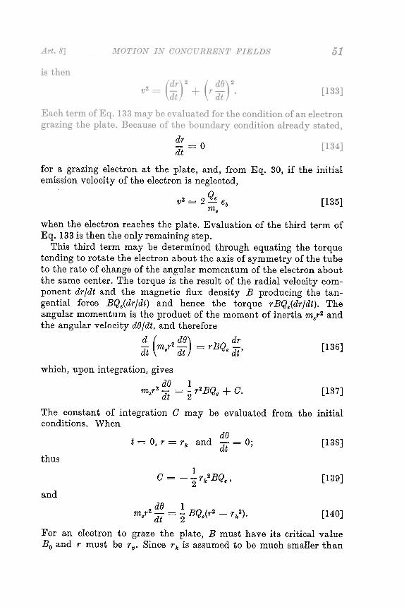
drdt
= 0
when the electron reaches the plate . Evaluation of the third term ofEq . 133 is then the only remaining step .
This third term may be determined through equating the torquetending to rotate the electron about the axis of symmetry of the tubeto the rate of change of the angular momentum of the electron aboutthe same center . The torque is the result of the radial velocity component
dr /dt and the magnetic flux density B producing the tangential force BQe(dr /dt ) and hence the torque r BQe(dr /dt ). The
angular momentum is the product of the moment of inertia mer2 andthe angular velocityd (j/dt , and therefore
d ( 2 dfJ) drat mer dt = r B Qedt' [136]
which , upon integration , givesd() Im r2 - - - r2BQ + 0e dt - 2 e . [137]
The constant of integration 0 may be evaluated from the initialconditions . When
[138]thus
[139]and
For anBo and
d()t = 0, r = rk and ;It = 0;
G = - ~rk2 B Qe'2
2 d() - I BQ 2 2)merd - - e(r - rk .t 2 [ 140 ]
electron to graze the plate , B must have its critical value
r must be r ' P . Since rk is assumed to be much smaller than
for a grazing electron at the plate , and, from Eq . 30, if the initialemission velocity of the electron is neglected,
QV2 = 2 --!.. eb [135]
me

Equations 143 and 144 give the critical value of the magnetic fluxdensity at which the anode current is interrupted as the flux densityis increased . They show that the current in a tube with a large anoderadius and small plate voltage may be interrupted by a smaller magnetic
flux density than for the opposite conditions . Fig . 19 presents the
general form of the characteristic curves of a cylindrical -anode mag -netron . The dotted lines indicate the idealized characteristics based on
Eq . 143 ; the solid lines the experimental ones . The difference betweenthe idealized and the experimental curves results from the influence of
52 ELECTRON BALLISTICS [Ch. l
with r 2)2. Thus, from Eq. 140r 21' rk2 may be neglected in comparisonis obtained d() 1 Qrat = '2 Bo -r1 r 2) [141]eas the value to be used in the third term of Eq . 1.33 when the electronjust grazes the plate .
B1< B2< B3 eb,< eb: < eb" -0'........~Q):..:..::3(.)Q).....ro~0 Magnetic flux density B
(a) (b)Characteristic curves of a magnet ron .Fig. 19.
2 Q e 1 B 2 (Q e ) 2 2- eb = - 0 - r J)me 4 meJ1 meBo = - 8 -Q eb.rJ) e
Substitution of the numerical value of ~ fromme
[142]or
[143]
Eq. 3 yields, in the
mks system,~
10- 6 - ! ! webers per square meter .r1)
Bo = 6.74 X ~[144]
The values from Eqs. 134, 135, and 141 may be substituted intoEq . 133 to obtain the relation

magnet ron
Art . 8] MOTIONIN G Ol'v T G U R RE N T FIELDS
Fig. 20. Magnet ron oscillator circuit.
~~.
t' - : >
-second under pulsed conditions . (CourtesyCompany.)
Cutaway view showing internal construction of acapable of generating 50 kilowatts of peak power at 3200 megacycles per
Raytheon Manufacturing

54 ELECTRON BALLISTICS [Ck . I
such causes as the initial velocities of the electrons at the cathode , the
fringing of the electric field , the voltage drop along the cathode, anddeviations of the cathode from true axial alignment .
An early form of the magnet ron for use as .an oscillator to generatehigh -frequency power involves separation of the anode into twosegments39 as is shown in Fig . 20. The two semicylinders are connected
to the opposite ends of a resonant circuit with a return path
through a direct -voltage source to the cathode. Frequencies of theorder of 300 megacycles per second and higher can be generated in thisway wiOth relatively high efficiency .
Placing the resonant circuit inside the tube ,4O and increasing thenumber of pairs of anode segments , have made possible production offrequencies as high as 30,000 megacycles per second and instantaneouspower outputs of several million watts . The internal structure of a
typical magnet ron for high ..frequency generation is shown in Fig . 21.Each slot and associated hole forms a resonant cavity that is excitedto oscillation by the passage of electrons across its mouth .
At the high frequencies produced by magnet ron oscillators theelectric field changes in magnitude during the passage of an electronfrom the cathode to the anode . Hence the conditions are no longerthose of static fields , and the analysis of the behavior of the tubesrequires that the time variation of the electric field be taken into
account . Other tubes in which this time variation is important arediscussed inChIV .
PRO B L El \ IS
1. ' \ ~ at is the speed of an electron in miles per second after it has movedthro ~gh a potential difference of 10 volts ?
2. An electron and another particle , starting from rest , fall through a potentialdifference E in an electrostatic field . The particle has the same charge as theelectron and 400 times the mass of the electron .
(a) Is the time of flight of the particles affected by the distribution of potentialwhich they encounter on their journey ?
(b ) For a given potential distribution , do the times of flight of the two particlesdiffer ? If so, by how much ?
(c) ' :v'hat is the kinetic energy of each of the particles at the end of the journey ?
3. Assume the parallel plane plates of Fig . 2 to be large and spaced 1 cm apartin vacuum . Instead of the battery sho~-n, an impulse generator with polarity as
39 G. R . Kilgore , " Magnet ron Oscillators for the Generation of Frequencies between300 and 600 Megacycles ," I .R .E . Proc ., 24 ( 1936 ), 1140- 1157 ; L . Rosen , " Characteristics
of a Split -Anode :1\Iagnetron Oscillator as a Function of Slot Angle ," R .S.I ., 9
(1938 ), 3i2 - 373 .
40 E . G . Linder , " The Anode -Tank -Circuit Magnet ron ," I .R .E . Proc ., 27 (1939 ),732- 738 ; J . B . Fisk , H . D . Hagstram , and P . L . Hartman , " The Magnet ron as aGener -ator of Centimeter v Vaves ," BiS .T .J ., 25 (1946 ), 1- 188.

55PROBLE.iiIS
indicated supplies a potential difference which increases at a uniform rate fromzero to one volt in 10- 8 sec. At the end of this time the plates are short -circuited .
(a) If an electron is at rest very near the negative plate at the beginning of thevoltage pulse , where is it at the time of short circuit ?
(b ) What is the total electron transit time to the positive plate ?
4. Two large plane plates separated by a distance of 1 cm in a high vacuumare arranged as shown in Fig . 2. Instead of the battery , an alternating squarewave of voltage having an amplitude of 1 volt and a period of 2 X 10- 8 sec isimpressed between the plates .
If an electron is at rest near the negative plate at the beginning of the firstcycle , where will it be at the end of that cycle ?
. 5. Two large plates separated b)r adistanced in a high vacuum are arranged asshown in Fig . 2 . Instead of the battery a voltage source of instantaneous value
eb = Em COS (wt + lp)
js applied between the plates . The electric field between the plates js essentiallyuniform at any instant of time . Electrons are emitted from the left -hand plate andmay be assumed to have zero initial velocity .
(a) Derive a general expression for the position of an emitted electron withrespect to the left -hand plate as a function of time .
(b ) Is it possible that some of the emitted electrons may never reach the righthand plate ? Either show that this condition cannot occur , or derive the
conditions for which it can occur .
6. An electron is initially at rest at the surface of the left -hand plate of theparallel -plate configuration shown in Fig . 2. Instead of the battery a sinusoidalvoltage source having a I -volt peak value and a frequency of 50 megacycles persecond is applied to the plates . The voltage is passing through its zero value at theinstant of application and is increa ~ing in the direction which makes the righthand
plate positive . The plates are infinite in extent and are placed 1 cm apartin vacuum .
(a) What is the maximum speed attained by the electron , and at what positionsdoes this speed occur ?
(b ) What is the speed of the electron at time t equals 2 X 10- 8 sec?(c) Describe completely the motion of the electron .
7. The screen of an electron oscilloscope is 20 cm from the anode . Two electronspass through the aperture in the anode traveling in parallel paths 0.1 mm apart .
(a) The electrons are 0.11 mm apart when they reach the screen . ' vnat is theirtransit time from anode to screen ?
(b ) If it is assumed that the electrons started from rest at the cathode , what isthe accelerating voltage of the anode ?
(c) Determine the anode accelerating voltage corresponding to an electronseparation of 0.101 mm at the screen .
8. The voltages El and E in the diagram of Fig . 22 each have a magnitude of100 volts . An electron starts from rest at the left -hand electrode , passes throughthe hole in the center diaphragm , and finally reaches the anode on the right . Theleft -hand and right -hand electrodes are each 1 cm from the centrally locateddiaphragm .
(a ) With what energy in electron volts does the electron strike the electrode atthe right ?

IIII + I - IIII '
x
56 ELECTRON BALLISTICS [Oh. I
EE2 + .1- Ei-:L.. ~ E--z-j
r - d1
rp
x =Ox = dV = Vkt = O
Electrode configurationfor Frob . 8 .
Fig. 22.
Fig . 23. Electrodeconfiguration foridealized Bark hausen
oscillator of Probill .
10. A cathode -ray oscilloscope is built with a fluorescent screen deposited on ametallic conducting plate . A lead is available from the conducting screen . Threedifferent connections are tried as follows :
(1) The screen is left without connection , that is, insulated from the anode .(2) The screen is connected through a high resistance to the anode .(3) The screen is connected directly through a low -resistance wire to the
anode .
If secondary emission from the screen is neglected :
(a) How do the velocities of the electrons as they reach the screen differ in thethree cases?
(b ) Which of the connections should be employed in practical use of the tube ?
11. In a Bark hausen oscillator , the grid of a triode is maintained at a positivepotential , and the plate is maintained at essentially the cathode potential . Thetransit time of the electrons in such an electrode configuration is to be found .
In order to obtain an approximate solution , consider that the vacuumtriode has parallel plane electrodes as shown in the diagram , Fig . 23, with interelectrode
spacings d1 and d2, each equal to 1 cm . 1'he plate p and cathode k areconnected together , and the grid g is maintained at a positive potential of 100volts with respect to them . The space charge is negligible , so that the potentialdistribution is an inverted V with its apex at the grid . An electron leaves thecathode with zero velocity . It may be assumed that the electron passes freelythrough the grid structure .
(b ) On the assumption that the electrodes are infinite parallel plates , what isthe time of transit of the electron between the left -hand electrode and thediaphragm ?
(c) On the same assumption , what is the time of transit of the electron betweenthe diaphragm and the right -hand electroded
) If the voltage E is changed to 200 volts , what then is the answer to (c) ?
9. An electron is moving at a speed of 108 cm per sec. Through how many voltsof potential difference must it pass to double its speed ?

E~
where x is in centimeters , and the field may be considered to be entirely in thevertical direction and to be directed upward within the space under consideration .
57PROBLEMS
Fig. 24. Configuration forFrob . 14.
Fig. 25. Diverging plate arrangementof Prob . 15.
Q 200b1l = volts per em,x+4
14. Two large capacitor plates are spaced adistanced apart and charged to apotential difference E as shown in Fig . 24. It may be assumed that the fieldintensity between the plates is uniform and that there is no fringing . A stream ofelectrons is projected at a velocity corresponding to an accelerating voltage Eointo the electric field at the edge of the lower plate and at an angle () with theplates .
(a) Find the relation among the voltages and () necessary in order that theelectrons may just miss the upper plate .
(b ) If () is 30 , d is 1 cm , and E is 50 volts , what initial kinetic energy should theelectrons in the beam have in order that they may just miss the upperplate ? Express the result in electron volts and joules .
15. An electron gun shoots an electron horizontally into an electric field established by a pair of diverging plane electrodes , with a velocity corresponding to a
kinetic energy of 400 electron volts , as shown in Fig . 25. At any distance x from. the origin , the electric field intensity is assumed to be given by the following
approximate expression
(a) ' vnat time elapses before the electron reaches the anode ?(b) On the assumption that the grid may be moved with respect to the plate
and cathode , show what effect the location of the grid has on the transittime of an electron from cathode to anode . Is there a position of the gridthat gives a minimum transit time ? If so, where is it ?
12. Find the electrostatic deflection sensitivity of the cathode -ray tube ofFig . 5 in volts per centimeter , ifd is 1 cm , lis 4.5 cm , and ls is 33 cm , for accelerating
voltages Eb of 300, 1,000, 5,000, and 10,000 volts .
13. Electrons accelerated by a potential difference of 1,000 volts are shot tan -gentlally into the interspace between two concentric semicylinders of radii 4 cmand 5 cm respectivel )". What potential difference must be applied between theplates to make the electron paths circular and concentric with the plates ?
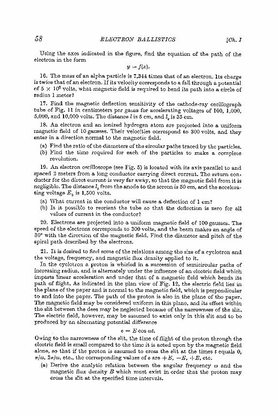
58 ELECTRONBALLISTICS [Ok. I
Using the axes indicated in the figure , find the equation of the path of theelectron in the form
y = j (x ).
16. The mass of an alpha particle is 7,344 times that of an electron . Its chargeis twice that of an electron . If its velocity corresponds to a fall through a potentialof 5 X 10⁶ volts , what magnetic field is required to bend its path into a circle ofradius 1 meter ?
17. Find the magnetic deflection sensitivity of the cathode -ray oscillographtube of Fig . incentimeters per gauss for accelerating voltages of 100, 1,000,5,000, and 10,000 volts . The distance lis 5 cm , and ls is 35 cm .
18. An electron and an ionized hydrogen atom are projected into a uniformmagnetic field of 10 gausses. Their velocities correspond to 300 volts , and theyenter in a direction normal to the magnetic field .
(a) Find the ratio of the diameters of the circular paths traced by the particles .(b ) Find the time required for each of the particles to make a complete
revolution .
19. An electron oscilloscope (see Fig . 5) is located with its axis parallel to andspacedmeters from a long conductor carrying direct current . The return conductor
for the direct current is very far away , so that the magnetic field from it is
negligible . The distance ls from the anode to the screen is 50 cm , and the accelerating voltage Eb is 1,500 volts .
(a ) " ' That current in the conductor will cause a deflection of 1 cm ?
(b ) Is it possible to reorient the tube so that the deflection is zero for allvalues of current in the conductor ?
20. Electrons are projected into a uniform magnetic field of 100 gausses. Thespeed of the electrons corresponds to 300 volts , and the beam makes an angle of300 with the direction of the magnetic field . Find the diameter and pitch of thespiral path described by the electrons .
21. It is desired to find some of the relations among the size of a cyclotron andtpe voltage , frequency , and magnetic flux density applied to it .
In the cy~lotron a proton is whirled in a succession of semicircular paths ofincreasing radius , and is alternately under the influence of an electric field whichimparts linear acceleration and under that of a magnetic field which bends itspath of flight . As indicated in the plan view of Fig . 12, the electric field lies' inthe plane of the paper and is normal to the magnetic field , which is perpendicularto and into the paper . The path of the proton is also in the plane of the paper .The magnetic field may be considered uniform in this plane , and its effect \vithinthe slit between the dees may be neglected because of the narrowness of the slit .The electric field , however , may be assumed to exist only in this slit and to beproduced by an alternating potential difference
e = E cos wt .
Owing to the narrowness of the slit , the time of flight of the proton through theelectric field is small compared to the time it is acted upon by the magnetic fieldalone , so that if the proton is assumed to cross the slit at the timest equals 0,1T/W, 21T/W, etc ., the corresponding values of e are + E , - E , + E , etc .
(a) Derive the analytic relation between the angular frequency W and themagnetic flux density B which must exist in order that the proton maycross the slit at the specified time intervals .

PROBLEMS
- Electronbeam
59
Fig . 26. Hollow cylinder of Frob . 23.
between cathode and anode is 200 volts . The distance from the anode to the screen
is 20 cm , and the cathode is 5 mm from the anode .
The tube is placed in a long solenoid of 10 cm diameter having six turns per
centimeter along its entire length , the tube and solenoid axes coinciding .
What is the smallest value of current in amperes in the coil that will produce
a magnetic effect on the beam of electrons sufficient to cause them to focus on a
spot the same size as the hole but at the screen ?
23 . An electron gun directs a beam of I , OOO - volt electrons through a hole A in
the wall of a hollow cylinder 2 cm in diameter , as indicated in Fig . 26 . The axis of
. the gun intersects that of the cylinder at an angle e . The cylinder wall has another
hole B , removed 900 circumferentially and 5 cm axially from the hole A .
Determine the angle e , and the density B and direction of the uniform axial
magnetic field required to cause the electron beam to emerge from the hole B .
24 . A region in space is permeated by a constant electric field parallel to the
'x axis and a constant magnetic field parallel to the y axis in a system of rectangular
co - ordinates .
(b) If the speed of the proton in its final semicircular path is to correspond to106 volts , and the magnetic flux density is 1,000 gausses, what will be theradius of the final path and what must be the angular frequency w of thevoltage e?
(c) Is the direction of travel of the proton counterclock Vw.ise as shown orclockwise?
22. Electrons emerge from a small hole in the anode of a cathode-ray tube in alldirections contained in a cone of small angle. The accelerating potential difference
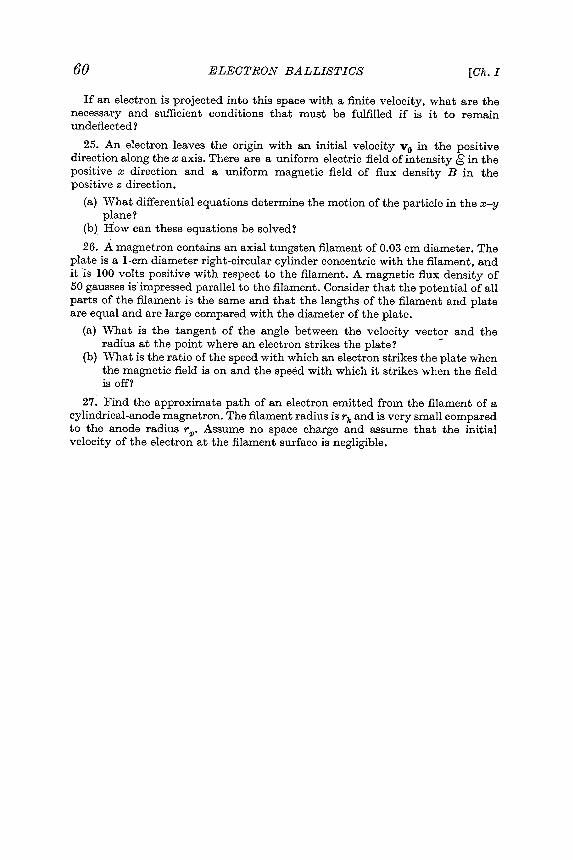
60 ELECTRONBALLISTICS [Ch. I
If an electron is projected into this space with a finite velocity , what are thenecessary and sufficient conditions that must be fulfilled if is it to remainundeflected ?
25. An electron leaves the origin with an initial velocity Vo in the positivedirection along the x axis . There are a uniform electric field of intensity 6 in thepositive x direction and a uniform magnetic field of flux density B in thepositive z direction .
(a) What differential equations determine the motion of the particle in the x- yplane ?
(b ) How can these equations be solved ?
26. A magnet ron contains an axial tungsten filament of 0.03 cm diameter . Theplate is a lcmdiameter right -circular cylinder concentric with the filament , andit is 100 volts positive with respect to the filament . A magnetic flux density of50 gausses is impressed parallel to the filament . Consider that the potential of allparts of the filament is the same and that the lengths of the filament and plateare equal and are large compared with the diameter of the plate .
(a) \ Vnat is the tangent of the angle between the velocity vector and theradius at the point where an electron strikes the plate ? -
(b ) \ vnat is the ratio of the speed with which an electron strikes the plate whenthe magnetic field is on and the speed with which it strikes when the fieldis off ?
27. Find the approximate path of an electron emitted from the filament of acylindrical -anode magnet ron . The filament radius is rk and is very small comparedto the anode radius r 1>. Assume no space charge and assume that the initialvelocity of the electron at the filament surface is negligible .