Embed Size (px)
Citation preview
E:\PowerPoint\Electron Beam Technology and Coatings\Electron Beam Technology and coatings_2.doc
ELECTRON BEAM TECHNOLOGY AND COATINGS
AK-Sitzung – FH-München
June 2006
B. Laurell, E. Föll Electron Crosslinking AB
Skyttevägen 42 SE-302 44 Halmstad
Sweden
Page 2 of 15
1. INTRODUCTION More environmental protection requirements force users of solvent-based coating to look for an environmentally safe procedure which emit considerably less solvents or cracked products into the atmosphere and water. Also the new EC Super directive regarding migration of less then 10 ppb into the food will force the packaging producer to look for new technologies. [28] The chemistry has new groups of products to offer:
- System with low content of solvents and with high solid contents - Coating material containing water - Coating with solid resin in powder form - 100 % solid system.
A common feature of the first three methods is that heat is required for the formation of dry coating film. Interesting techniques which do not induce these disadvantages of thermal drying are the radiation curing – in particular those involving ionising radiation such as ultraviolet or electron-beam curing. Radiation Curing
- IR Infra-red System containing solvents - Micro-wave Water-based system
- UV Ultraviolet light 100 % system - EB Electron Beam 100 % system
UV-ultraviolet light can be used without problems for curing in those places that are accessible to ”UV-light”, i.e. the layers which the radiation must pass trough, must be thin and transparent at the appropriate wavelengths. The formulation will contain photo initiators and other absorbing materials like pigment and matting agents. During the curing process there should be no emission of harmful substances into the atmosphere, water or into the food. In addition, after the curing process is over, there should be no odour emissions from the surface. These requirements has already given Electron Beam curing (EB) the focus of even more attention, not least as this technology has been used for a wide variety of applications in recent years due to the many other benefits it offers. EB is the abbreviation for an environmentally safe, heat and solvent free technique: Electron-Beam curing. Nevertheless, success is only possible if the user, the chemical supplier and the plant manufacturer collaborate fully - not only during the planning phase but also during the construction of the curing line and later during initial operation.
Page 3 of 15
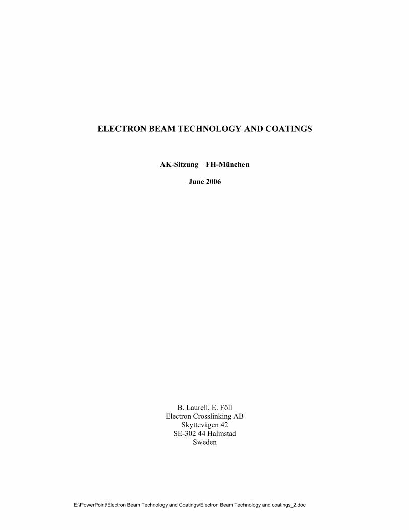
2. THE ACCELERATOR The functioning of the electron beam accelerator can best be compared with the cathode ray tube of a TV. Fig. 1.
Fig. 1.: Cathode ray tube and the Electron Crosslinking electron beam accelerator A tungsten cathode heated in high vacuum by an electrical current makes free electrons available on its surface. In a TV set the electrons (negatively charged particles) are accelerated by a high negative voltage towards the anode and then deflected to the screen, or to the electron-beam exit window in the electron-beam accelerator. In the accelerator these electrons then emerge from the vacuum through a thin piece of titanium foil into the air or an inert gas where they can act upon the material.
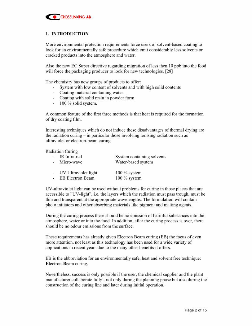
Fig. 2: Picture of Electron Beam Accelerator, 250 kV accelerating voltage and 1,20 m working widths.
Page 4 of 15
3. ENERGY TRANSFER The transfer of energy from the electron beam into material is specified completely by four parameters:
• Depth of penetration • Absorbed dose • Beam uniformity • Throughput
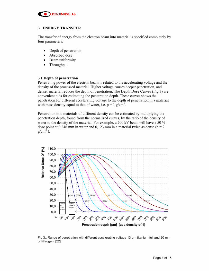
3.1 Depth of penetration Penetrating power of the electron beam is related to the accelerating voltage and the density of the processed material. Higher voltage causes deeper penetration, and denser material reduces the depth of penetration. The Depth Dose Curves (Fig 3) are convenient aids for estimating the penetration depth. These curves shows the penetration for different accelerating voltage to the depth of penetration in a material with mass density equal to that of water, i.e. p = 1 g/cm3. Penetration into materials of different density can be estimated by multiplying the penetration depth, found from the normalized curves, by the ratio of the density of water to the density of the material. For example, a 200 kV beam will have a 50 % dose point at 0,246 mm in water and 0,123 mm in a material twice as dense (p = 2 g/cm3 ).
0,0
10,0
20,0
30,0
40,0
50,0
60,0
70,0
80,0
90,0
100,0
110,0
0 50 100
150
200
250
300
350
400
450
500
550
600
650
700
750
800
850
900
Penetration depth [µm] (at a density of 1)
Rel
ativ
e D
ose
D* [
%]
Titanium-foil13 µm59 g/m2
150 kV
175 kV
200 kV
225 kV
250 kV
275 kV
300 kV
125 kV
100 kV75 kV
Inerting20 mm N225 g/m2
Fig 3.: Range of penetration with different accelerating voltage 13 µm titanium foil and 20 mm of Nitrogen. [22]
Page 5 of 15
At accelerating voltages of 150, 180 and 250 kV respective curing depth of 86, 138 and 277 g/m2 are achieved at 80 % ionisation. Experienced values for industrial accelerating voltages are as follows:
- 80 – 150 keV thin layers in the field of printing inks or silicon-release materials, sterilisation
- 165 – 180 keV furniture foil, pressure-sensitive adhesives - 180 – 250 keV boards, parquet, panels, lamination - 250 – 300 keV composite
3.2 Absorbed Dose Absorbed dose is defined as the amount of energy deposited into a specified mass of material. The unit of absorbed dose is kilogray (kGy), defined as the number of joules (J) of energy deposited into 1 kilogram (kg) of material. An older, but frequently used unit, is megarad (Mrad). 1 kGy = 1 kJ/kg 1 Mrad = 10 kGy = 10 J/g = 2,4 cal/g
- Heating of water 1 degree 1 cal/g - Evaporation of water 540 cal/g - EB-curing of lacquer approx. 10 cal/g
At a fixed electron accelerating voltage, the dose is directly proportional to the electron beam current. The dose D [kGy] is proportional to electron current I [mA] and inverse to web speed v [m/min] as follows:
vIkD ×=
the k factor is depending on the equipment and the accelerating voltage. The formula above shows:
- dose and electron current are directly proportional - if the ratio of electron current and speed are kept constant the dose is constant
including start up and shut down of the plant - the accelerator uses only the quantity of power from the main supply needed
for the used web speed - quality improvements
Page 6 of 15
Typical values of the dose needed for practical applications are:
- Drying/curing of inks and coatings 15-30 kGy - Crosslinking of plastic films 25-150 kGy - Sterilization of medical products 7.5-35 kGy - The certified dose to sterilize :7 log decrease is 25 kGy [27]
3.3 Beam Uniformity Beam uniformity is a direct function of how the electron beam is distributed over working width. It is specified as a percentage deviation from the average value, e.g. 20 kGy ± 10%. In general, Electron Crosslinking Accelerator provides a uniformity better then ± 5%; many applications can tolerate variations of ± 10% or more. 3.4 Throughput Throughput is a measure of the energy deposition rate and relates directly to the amount of material that can be processed within a given time interval. It is measured in kilogray per second, abbreviated kGy/s. An Accelerator specified to 10 000 kGy m/min can provide a dose of 25 kGy when the web speed is 400 m/min, or 50 kGy at 200 m/min, etc. The processor will automatically adjust the beam intensity as the web speed changes so that the dose remains constant. 4. APPLICATIONS In all applications the Electron Beam Accelerator itself is the same but the handling system differs:
- material in solid form, as sheet, board, panels etc. - flexible materials, roll to roll - laboratory equipment
4.1 Solid materials In the surface converting of solid materials the EB-technology is successfully used in the following operating fields: Curing of top lacquer on doors [1], [2] All-around curing of coated profiles [3], [4] Curing of the coating on raw boards in the wood industry [5], [6] Curing of the coating on architectural claddings for outside applications [7], [8] Curing of the coating on wood-cement boards for outside and inside application [9] Curing of impregnation and top lacquer on laminated boards
Page 7 of 15
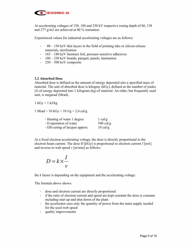
Curing of coated edges and panels in the wood and laminate industry [10] Curing of coatings on MDF boards (Medium-Density-Fibre-board) [11], [12], [13] Curing of coatings on three-dimensional parts e.g. rims and pumps housings. Sterilization 4.1.1 Claddings for outside applications The coating line receives the produced panels directly from the production line. The panels, which are made in dimensions from 600 x 150 mm to 3500 x 1250 mm with a thickness of 4 - 30 mm, are cut into final customized dimensions before they come to the coating line.
Fig. 4: Electron-beam equipment for boards application (schematically).
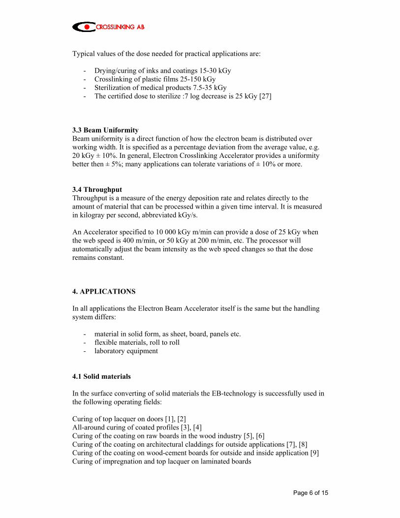
Fig. 5: Installation for composite facade panels. (250 kV, 150 mA, 1,2 m)
Page 8 of 15
In order to use the capacity of the line, a group of panels is formed, where the total dimension automatically are optimised as close as possible to the maximum dimension. This group, often called “batch“, is then transported through the complete coating line as one unit. One batch can contain up to 20 panels, that are coated in one operation. This way of transportation lead to an optimal use of capacity in combination with a good flexibility for painting customer-unique cut panels. This technology provides a surface of the facade panels, made for outdoor use, which is extremely resistant to UV-light as well as weather (cold, heat, rain, wind). In combination with the demands on production speed and the ability to handle the panels immediately after painting, the choice of EB-technology was natural. 4.2 Flexible materials In the surface converting of flexible materials the EB-technology is successfully used in the following operating fields: Vulcanisation or crosslinking of pressure-sensitive adhesives [14] Curing of high-gloss coating of special paper (e.g. photographic paper) [15], [16],[17] Curing of release coatings Curing of web offset printing inks, finishing varnishes [18], [21] Crosslinking of films and foils Production of antistatic finish Crosslinking of flock adhesives Curing of intaglio prints [18], [19], [20] Post-crosslinking of binding agents of magnetic materials Metallizing of paper, e.g. curing of basic lacquer and adhesives for selective or plane transfer metallizing as well as curing of overprints Curing of metal coating from roll to roll (coil coating) Stabilisation of rubber raw materials by partial vulcanisation Crosslinking of laminating adhesives Crosslinking of thin insulation of wire and cables Colouring of textiles Sterilization
Page 9 of 15
4.2.1 Installation for flexible material, roll to roll
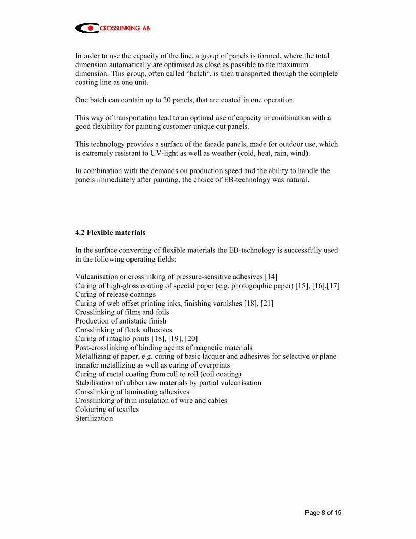
Fig. 6: Electron-beam equipment for roll to roll application (schematically). Acceleration voltage max. 280 kV, penetration max. 320 g/m2 at an ionisation of 80 %. Dose capacity at 800 m/min = 10 kGy. Dose accuracy over the working width better than ± 3 %. 1 Accelerator with two cathodes. 2 High-voltage cable. 3 Scanning system. 4 Pumping system. 5 Electron-beam exit window, inertisation zone, disconnection point for
maintenance work. 6 Drum for material supply. 7 Material inlet / outlet. 8 Radiation shielding. The electron accelerator is positioned horizontally and is aimed towards a drum. The drum can be cooled or heated. Together with a large-surface electron-beam exit window, the drum can be heated up to temperatures of 100°C. The exit window can be operated at temperatures of up to 70°C. This is an interesting variation of the application technique, particularly with respect to monomer-free materials applied at higher temperatures, and according to the chemicals used, crosslinked in a hot state. The drum serves to guide the material during the hardening or vulcanisation process and is indispensable for hardening of the lacquer (especially on thin, highly flexible substrates), fig. 6.
Page 10 of 15
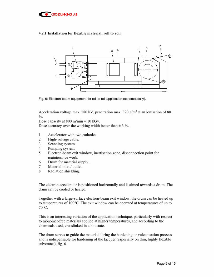
Using a drum permits inertisation of the process zone.
Fig. 7: EB unit for irradiation of material from roll to roll. (280 kV, 400 mA, 1,2 m) The positioning of the drum described before is not only suitable for crosslinking and vulcanisation of lacquers and pressure-sensitive substances but is also quite advantageous in crosslinking adhesives when manufacturing laminated material for the packaging industry. 4.2.2 Installation for flexible material, roll to roll
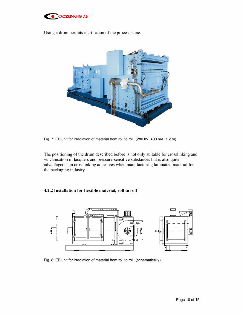
Fig. 8: EB unit for irradiation of material from roll to roll. (schematically).
Page 11 of 15
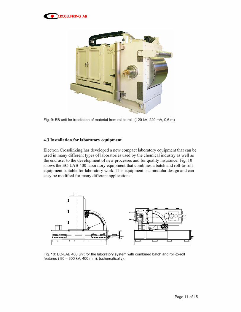
Fig. 9: EB unit for irradiation of material from roll to roll. (120 kV, 220 mA, 0,6 m) 4.3 Installation for laboratory equipment Electron Crosslinking has developed a new compact laboratory equipment that can be used in many different types of laboratories used by the chemical industry as well as the end user to the development of new processes and for quality insurance. Fig. 10 shows the EC-LAB 400 laboratory equipment that combines a batch and roll-to-roll equipment suitable for laboratory work. This equipment is a modular design and can easy be modified for many different applications.
Fig. 10: EC-LAB 400 unit for the laboratory system with combined batch and roll-to-roll features ( 80 – 300 kV, 400 mm). (schematically).
Page 12 of 15
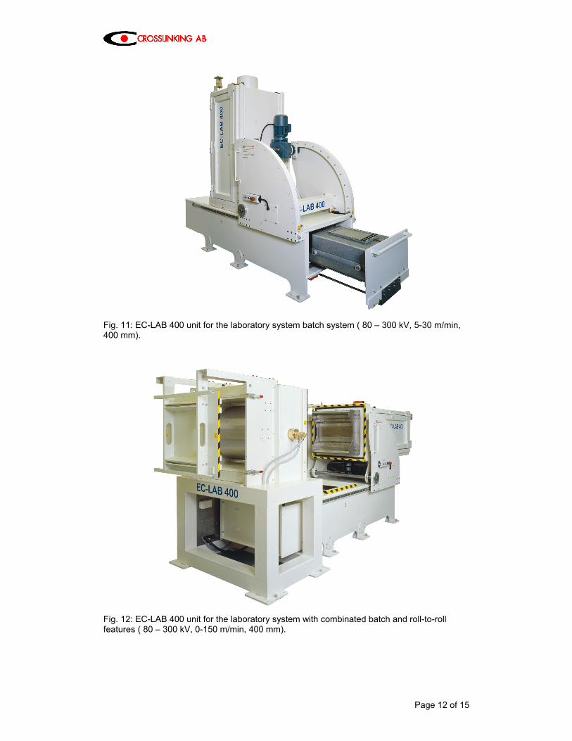
Fig. 11: EC-LAB 400 unit for the laboratory system batch system ( 80 – 300 kV, 5-30 m/min, 400 mm).
Fig. 12: EC-LAB 400 unit for the laboratory system with combinated batch and roll-to-roll features ( 80 – 300 kV, 0-150 m/min, 400 mm).
Page 13 of 15
5. EB -CURING The advantages of Electron Beam curing is:
• Environmentally friendly due to a 100 %-solid system. EB generates absolutely no emissions.
• No substrate heating. • Low energy consumption. • Substantial production increase compared with conventional heat-treatment
methods and UV-technology, also with pigmented layers. • Immediate further treatment of converted products without post curing. • Low space requirement. Integration into existing production processes without
any problems. • Exact repeatability of production conditions is obtained due to high dose
accuracy. There is also no wastage when starting up and shutting down the plant.
The surface treated with EB-technology is:
• free of harmful substances • non-ageing • weather-resistant • scratch-proof • colour-stable • resistant to organic solvents • resistant to a wide range of chemicals.
Page 14 of 15
6. SUMMARY What has to be done in the near future regarding chemistry? Wood Coatings
• Products with less extractables • Products with high scratch & abrasion resistance
Graphis
• Printing inks, OPV`s and adhesives with approval for food packaging Plastic & Meal Coatings
• Adhesion promoters • Products for coil coating
It is also important to develop systems in general, demanding less dose to achieve a higher production capacity. Electron-Beam curing has overcome its limits and is heading to new applications. Electron-Beam has a growing attention as an eco-efficient technology. The growth rate in Europe for the Radiation Curing marked is estimated to 9 % yearly. In order to carry this technology on to success, good cooperation between customer, chemistry and plant manufacturers is necessary.
Page 15 of 15
7. Literature [1] Fa. Svedex, Türenfabrik, NL-7050 Varssefeld [2] Fa. Theuma N.V.S.A., Türenfabrik, B-3260 Bekkevoort-Assent [3] Profilleisten-Lackirung mit Rundum-Elektronenstrahltrocknong, HK-International
5/92 [4] A. Lindbladh, From Idea to Industrial Plant with EB-technique, RadTech Europé ’93
Mediterraneo, Conference Preceedings [5] Fa. Hamberger Industriewerke GmbH, D-83101 Rosenheim [6] Fa. Scannery Holztechnik GmbH, D-16928 [7] T. Alpar, Elektronenstrahlhärtung bei der Oberflächenveredelung von
Zementspanplatten, 13. Münchner Klebstoff-und Veredelungs-Seminar, 1988 [8] C. Chaix, N.Handegard, Electron beam coatings on polyester panels, Composites-NO
14-mars-Avril 1996 [9] U. Tenorth, Planung und Realisierung einer modernen ESH-Anlage zur Beschichtung
von Holz-Zement-Platten und Holz-Spanplatten, beta-gamma 1/90 [10] Dekorative Platten mit verbesserten Oberflächeneigenschaften, Hoechst AG,
Europäische Patentschrift 0 166 153 [11] Fa. Glunz GmbH, D-49716 Meppen, Interzum Köln 1993 [12] Lack-Design-Verfahren für Holzwerkstoffplatten, HK-International 1/94 [13] Fa. Astrid, I-33033 Codroipo (UD), Interzum Köln 1993 [14] P. Holl, Elektronenstrahler zur Vernetzung und Vulkanisation von Hot Melts,16.
Münchner Klebstoff-und Veredelungs-Seminar, 1991 [15] H.D. Diesel, H. Giegold, Folienveredelung mit Hilfe der ESH-Technik, 7. Münchner
Klebstoff- und Veredelungs-Seminar, 1982 [16] H. Haller, 15 years of EB-Technology with WKP, RadTech Europé ’93 Mediterraneo
Conference Preceedings [17] Fa. Taubert GmbH, D-46047 Oberhausen, Patentanmeldung P 42 19 446.6, Verfahren
zum Auftragen einer dekorativen Schicht auf ein Trägermaterial. [18] Fa. Tetra Pak, S-22186 Lund [19] EB lights the way to better film printing, Packaging Digest, April 1991 [20] P. Klenert, K-H. Krauß, H. Langguth, S. Rummel und R. Mehnert, Strahlenhärtung
von Druckfarben und analytische Charakterisierung, IOM – Institut für Oberflächenmodifizierung, D-04303 Leipzig
[21] P. Holl, E.Föll, Electron-Beam for Controlled Environmentally Friendly Through-Curing of Lacquers, Foils and Adhesives, RadTech Europé ’93, Mediterraneo, Conferrence Proceedings
[22] H. Neuhaus-Steinmetz, Penetration Depth of the Radiation Dose and Dose Yield for Low Energy Electron Beam Accelerators, Radtech ’93 Mediterraneo, Conference Proceedings
[23] P.Holl, Some new aspects on applications of EB curing, RadCureLetter 1/96 [24] J. McBosch, J.D.LeFors, T.Hetzel, Decorative Particle Board Surfaces via the UV/EB
Curing Process – 15 Years of Success, beta-gamma 2/88 [25] ISO / ASTM 51818-2005. Standard Practice for Dosimetry in an Electron Beam
Facility for Radiation Processing at Energies Between 80 and 300 keV. [26] Wolfgang Paulus. Status of UV/EB in Europe 2005 [27] ISO 11137 / EC standard 552 [28] EC regulation No 1935/2004 Directives 80/590/EEC and 89/109/EEC


![The MSU/NSCL Re-Accelerator ReA3 - JACoW.org · towards the electron beam ion trap (EBIT) where they are injected into the intense electron beam [5]. Inside the electron beam the](https://img.pdfslide.net/doc/110x75/5c1bc60609d3f206658b67e6/the-msunscl-re-accelerator-rea3-jacoworg-towards-the-electron-beam-ion-trap.jpg)