Embed Size (px)
Citation preview
Electron microscopy and microanalysis of steel weld joints after long time exposures at high temperatures
D Jandová1,3, J Kasl1 and A Rek2 1 Škoda Výzkum s.r.o., Tylova 1/57, CZ-31600 Plzeň, Czech Republic 2 Ústav přístrojové techniky AV ČR, Královopolská 147, CZ-61264 Brno, Czech Republic E-mail: [email protected]
Abstract. The structural changes of three trial weld joints of creep resistant modified 9Cr-1Mo steels and low alloyed chromium steel after post-weld heat treatment and long-term creep tests were investigated. Smooth cross-weld specimens ruptured in different zones of the weld joints as a result of different structural changes taking place during creep exposures. The microstructure of the weld joint is heterogeneous and consequently microstructural development can be different in the weld metal, the heat affected zone, and the base material. Precipitation reactions, nucleation and growth of some particles and dissolution of others, affect the strengthening of the matrix, recovery at high temperatures, and the resulting creep resistance. Therefore, a detailed study of secondary phase’s development in individual zones of weld joints can elucidate mechanism of cracks propagation in specific regions and the causes of creep failure. Type I and II fractures in the weld metal and Type IV fractures in the fine prior austenite grain heat affected zones occurred after creep tests at temperatures ranging from 525 to 625 °C and under stresses from 40 to 240 MPa. An extended metallographic study of the weld joints was carried out using scanning and transmission electron microscopy, energy-dispersive and wave-dispersive X-ray microanalysis. Carbon extraction replicas and thin foils were prepared from individual weld joint regions and quantitative evaluation of dislocation substructure and particles of secondary phases has been performed.
1. Introduction The steel of grade P91 is the main representative of creep resistant modified 9%Cr-1Mo steels. It is currently used for manufacturing of boiler and turbine components of fossil fuel power plants, which operate at temperatures up to 585 °C, especially steam piping and rotors, but also turbine casings, outlets and so on [1]. Production of these components includes welding as a standard procedure. The weld joints of this class of steels are susceptible to frequent failure, which is often initiated in specific microscopic region of a weldment either during fabrication or during service. This could be attributed to differences in the properties of various regions of weldment, due to the heterogeneity in microstructure. A high heterogeneity is expected not only in dissimilar weld joints, when different materials are joined, but also in similar weld joints. Therefore, it is necessary to perform creep testing of weld joints and to evaluate microstructural stability at different creep conditions. Especially long-term creep testing is of a great importance for life assessment of power plant equipment because some of microstructural changes occur only after several tens of thousands hours of creep exposure 3 To whom any correspondence should be addressed.
11th European Workshop on Modern Developments and Applications in Microbeam Analysis IOP PublishingIOP Conf. Series: Materials Science and Engineering 7 (2010) 012012 doi:10.1088/1757-899X/7/1/012012
1
[2]. The creep rupture strength for 105 hrs at operating temperature is a deciding criterion for the creep strength of power plant steels. Nowadays a life-time of steam power plants at least of 200,000 hours is required. The paper deals with investigation of trial weld joints of high alloyed P91 steel and low alloyed P22 steel intended for production of turbine components, which underwent creep testing and extended metallographic analyses [3-5].
2. The objectives of study • Evaluation of creep strength of trial weld joints made of P91 and P22 steel in comparison to the
creep strength of the base materials. • Determination of critical zones from the point of view of creep failure during long term creep
exposures at stresses and temperatures used in industrial service. • Study of microstructural changes taking place in individual zones of weld joints of the crept
specimens (the weld metal, the heat affected zones, the base material unaffected by welding). • Elucidation of the creep failure mechanism and causes of different types of ruptures in dependency
on creep conditions.
3. Experimental procedures Trial weld joints made of creep resistant steels, modified 9Cr-1Mo steel (grade P91) and 21/4Cr-1Mo steel (grade P22), were fabricated using GTAW and SMAW method: the similar plate weld joint (C), the similar pipe weld joint (C1) and dissimilar one (C2). Inductive heating with thermal isolation ensured a preheating temperature in the range (200 - 250) °C. The interpass temperature was kept below 300 °C. The first weld joint was produced of the plates of P91 steel with dimensions of 500 x 150 x 25 mm that were welded together in PA position. The similar pipe weld joint was made of P91 steel, the dissimilar one of P91/P92 steels. The segments of 325 mm outer diameter, 25 mm wall thickness and 400 mm length were joined in PC position.
The chemical compositions of the base materials and the weld metals are given in Table 1. Consumables of dissimilar weld joint were on the base of P22 steel. The base material of P91 steel was austenitized at 1050 °C for 1.5 hrs, oil quenched and tempered at 750 °C for 3.5 hrs. The base material of P22 steel was annealed and tempered at conditions (920 ÷ 960) °C / air + (680 ÷ 750) °C / air. The post-weld heat treatment (PWHT) was applied: (740 ÷750 °C) / 2.5hrs for the plate weld joint, 760 °C / 2.5hrs for the similar and 730 °C/2.5hrs / air for the dissimilar pipe weld joint.
Table 1. Chemical composition of the base materials and weld metals (wt%).
C Mn Si Cr Mo V Ni Nb Al N P S BM P91 plate 0.12 0.41 0.21 8.8 0.92 0.22 0.10 0.09 0.004 0.06 0.014 0.008BM P91 pipe 0.12 0.49 0.29 8.6 0.96 0.21 0.30 0.07 0.011 0.06 0.011 0.004BM P22 pipe 0.11 0.46 0.25 2.24 0.95 - - - - - 0.013 0.002WM weld C 0.12 0.71 0.23 9.1 1.05 0.20 0.68 0.05 0.005 0.04 0.012 0.009
WM weld C1 0.12 0.70 0.21 9.1 1.05 0.21 0.73 0.05 0.003 0.04 0.010 0.006WM weld C2 0.06 0.70 0.22 2.22 0.99 - - - - - 0.012 0.010
Creep test to rupture of smooth cross-weld specimens with a length of 92 mm and a diameter of
8 mm were performed. Fractographic and metallographic analyses of ruptured specimens were carried out using light (LM) and scanning electron microscopy (SEM). Metallographic samples were
11th European Workshop on Modern Developments and Applications in Microbeam Analysis IOP PublishingIOP Conf. Series: Materials Science and Engineering 7 (2010) 012012 doi:10.1088/1757-899X/7/1/012012
2
prepared of longitudinal section of creep tests specimens. Vickers hardness measurement across the weld joints and metallographic observation were performed. Changes of hardness after creep tests indicate significant changes of mechanical properties in individual zones of the weld joint. Microstructures of P91 and P22 steels were revealed using Villela´s reagent and 3 % nital solution, respectively. The concentration profiles of alloying elements in dissimilar weld joint were measured using energy-dispersive X-ray microanalysis (EDS) and wave-dispersive X-ray microanalysis (WDS). Carbon enriched and depleted zones near fusion lines were detected using the method of differential concentration [6]. The carbon concentration of the base materials were determined using spectral analysis. Then plus and minus concentration deviations were measured across the weld joint using WDS microanalyses along set of line segments, which were parallel to a fusion line. Each line segment substituted a point of line across the weld joint. Obtained deviations were hanged on the known carbon concentrations of the base materials and concentration profile was calculated. Size and distribution of particles of secondary phases in ferritic matrix were observed on metallographic samples using SEM and on extraction carbon replicas using transmission electron microscopy (TEM). Individual phases were identified using EDS microanalysis and selected area electron diffraction. Carbon extraction replicas were prepared from the weld metal and the base material separately. Thin foils for TEM were prepared from selected areas of the weld joints; from the weld metal (WM), the coarse prior austenitic grain heat affected zone (CG HAZ), the fine prior austenitic grain heat affected zone (FG HAZ) and the base material (BM) using jet electropolishing in 6 % solution of perchloric acid in methanol at a temperature ranged from -60 °C to -40 °C.
4. Results
4.1. Creep testing The creep rupture testing was carried out at the air at stresses in a range from 40 to 240 MPa and at temperatures ranged from 525 to 625 °C. The longest time to the rupture was 45,811 hrs. Obtained creep data were evaluated using Larson-Miller parametric equation P = T (C + log t), where T represents temperature given in degree Kelvin, C is a specific constant for a given material, and t means time to the rupture in hours. The creep strength of all weld joints investigated was sufficient; it fell into usually permitted ± 20 % scatter band of the creep strength of the corresponding base material in temperature range up to 575 °C. Dissimilar weld joint fulfilled this requirement even at 600 °C (figure 1) while the similar weld joints revealed decrease below the bottom of the considered scatter band at 600 and 625 °C (figures 2 and 3).
4.2. Fractography Fractures occurred in the HAZ (Type IV cracking), in the weld metal (Type I and II cracking) or in the base material in dependence on the creep test conditions. Fracture surfaces were covered with oxide layers nevertheless it was possible to distinguish typical ductile dimple morphology of fractures of similar weld joint, which ruptured at high stresses and relatively low temperatures, and also of all fractures of the dissimilar weld joint. Dimpling morphology, intercrystalline facets (figure 4) and cavities (figure 5) were found out on fracture surfaces of crept samples after long creep exposures at high temperatures.
The dissimilar C2 weld joint ruptured in the low alloyed base material unaffected by welding process at conditions of high stresses and relatively low temperatures of creep test, while Type I fractures occurred in the weld metal at low stresses and high temperatures (figure 1).
The similar C and C1 weld joints revealed Type I and II or Type IV cracking at different conditions for each of weld joints, although the chemical composition of the base materials and consumables and also welding process were almost identical. Fractures of C1 weld joint occurred in the weld metal at high stresses and relatively low temperatures (lower values of Larson-Miller parameter) and in the HAZ at low stresses and high temperatures (higher Larson-Miller parameter, figure 2). On the
11th European Workshop on Modern Developments and Applications in Microbeam Analysis IOP PublishingIOP Conf. Series: Materials Science and Engineering 7 (2010) 012012 doi:10.1088/1757-899X/7/1/012012
3
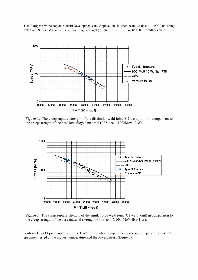
Figure 1. The creep rupture strength of the dissimilar weld joint (C2 weld joint) in comparison to the creep strength of the base low alloyed material (P22 steel - 10CrMo9 10 W).
Figure 2. The creep rupture strength of the similar pipe weld joint (C1 weld joint) in comparison to the creep strength of the base material (wrought P91 steel - X10CrMoVNb 9 1 W).
contrary C weld joint ruptured in the HAZ in the whole range of stresses and temperatures except of specimen tested at the highest temperature and the lowest stress (figure 3).
11th European Workshop on Modern Developments and Applications in Microbeam Analysis IOP PublishingIOP Conf. Series: Materials Science and Engineering 7 (2010) 012012 doi:10.1088/1757-899X/7/1/012012
4
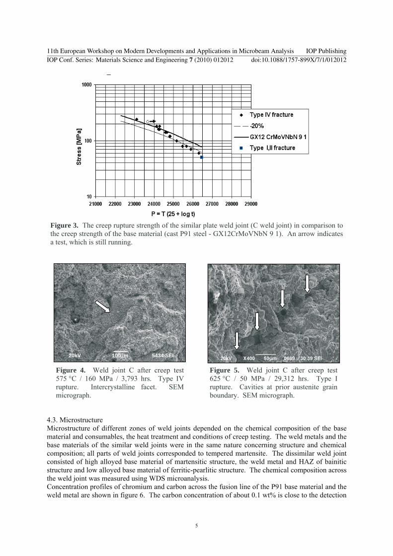
Figure 3. The creep rupture strength of the similar plate weld joint (C weld joint) in comparison to the creep strength of the base material (cast P91 steel - GX12CrMoVNbN 9 1). An arrow indicates a test, which is still running.
Figure 4. Weld joint C after creep test 575 °C / 160 MPa / 3,793 hrs. Type IV rupture. Intercrystalline facet. SEM micrograph.
Figure 5. Weld joint C after creep test 625 °C / 50 MPa / 29,312 hrs. Type I rupture. Cavities at prior austenite grain boundary. SEM micrograph.
20kV 100μm 5434 SEI
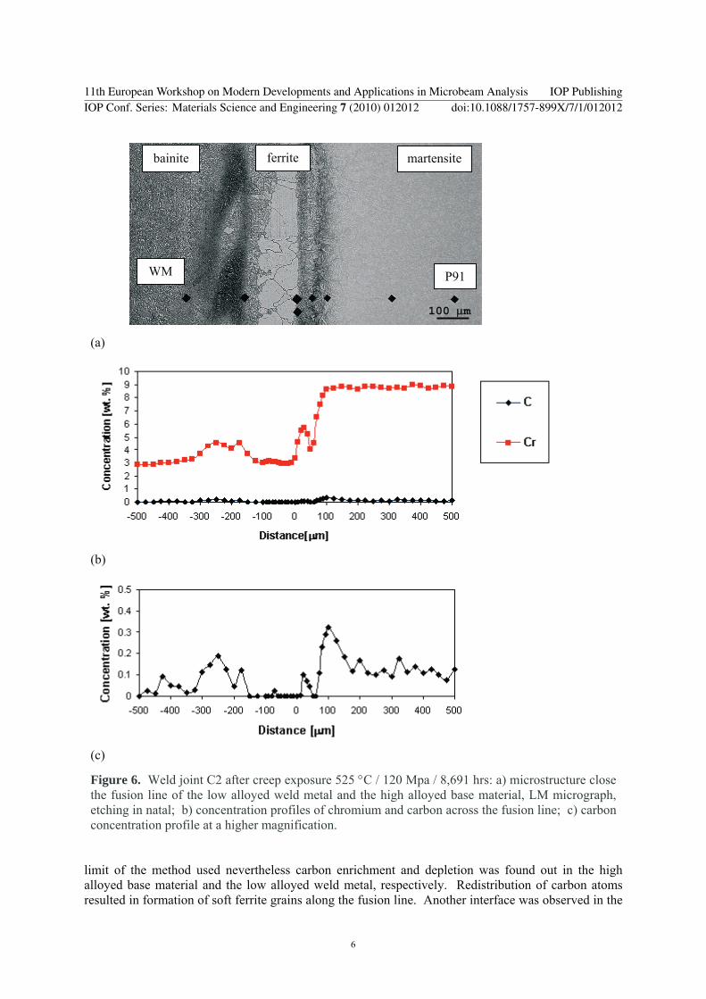
4.3. Microstructure Microstructure of different zones of weld joints depended on the chemical composition of the base material and consumables, the heat treatment and conditions of creep testing. The weld metals and the base materials of the similar weld joints were in the same nature concerning structure and chemical composition; all parts of weld joints corresponded to tempered martensite. The dissimilar weld joint consisted of high alloyed base material of martensitic structure, the weld metal and HAZ of bainitic structure and low alloyed base material of ferritic-pearlitic structure. The chemical composition across the weld joint was measured using WDS microanalysis. Concentration profiles of chromium and carbon across the fusion line of the P91 base material and the weld metal are shown in figure 6. The carbon concentration of about 0.1 wt% is close to the detection
11th European Workshop on Modern Developments and Applications in Microbeam Analysis IOP PublishingIOP Conf. Series: Materials Science and Engineering 7 (2010) 012012 doi:10.1088/1757-899X/7/1/012012
5
(a)
(b)
(c)
Figure 6. Weld joint C2 after creep exposure 525 °C / 120 Mpa / 8,691 hrs: a) microstructure close the fusion line of the low alloyed weld metal and the high alloyed base material, LM micrograph, etching in natal; b) concentration profiles of chromium and carbon across the fusion line; c) carbon concentration profile at a higher magnification.
limit of the method used nevertheless carbon enrichment and depletion was found out in the high alloyed base material and the low alloyed weld metal, respectively. Redistribution of carbon atoms resulted in formation of soft ferrite grains along the fusion line. Another interface was observed in the
P91 WM
martensite ferrite
100
bainite
μm
11th European Workshop on Modern Developments and Applications in Microbeam Analysis IOP PublishingIOP Conf. Series: Materials Science and Engineering 7 (2010) 012012 doi:10.1088/1757-899X/7/1/012012
6
weld metal between weld beads. Chromium enrichment (0.30 wt%) of the bead adjacent to the high alloyed base material and slight decrease (below 0.05 wt%) in carbon concentration on the side of low alloyed bead was found out. In this carbon depleted band sporadic occurrence of ferritic grains in bainite was noted.
Carbon depleted zones in weld joints are usually susceptible to fracture as their creep strength is lower than creep strength of surrounding matrix. However, cracks were not observed in these zones in dissimilar weld joint investigated. Fractures occurred in the low alloyed base material of mixed ferritic pearlitic structure or in the weld metal of bainite structure, particularly in the heat affected zones of weld beads.
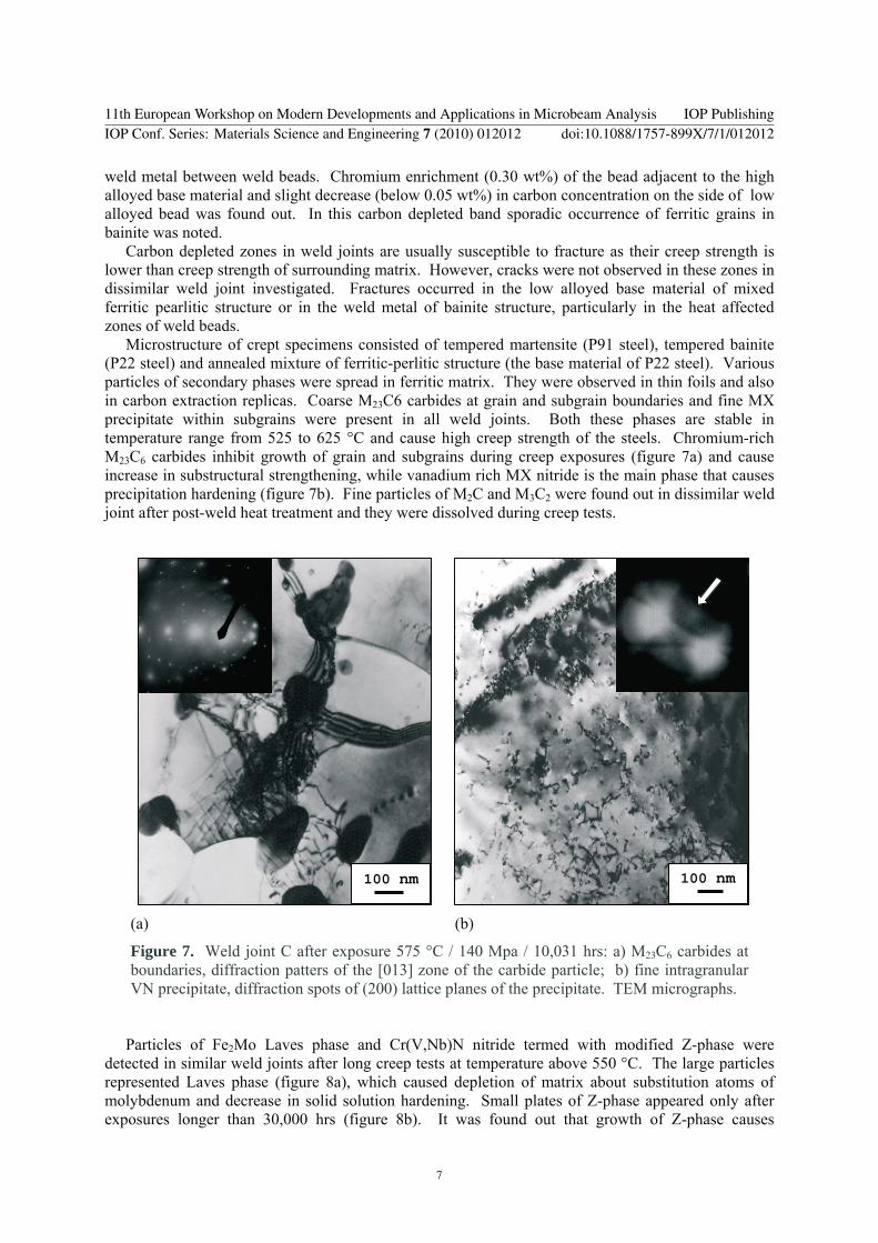
Microstructure of crept specimens consisted of tempered martensite (P91 steel), tempered bainite (P22 steel) and annealed mixture of ferritic-perlitic structure (the base material of P22 steel). Various particles of secondary phases were spread in ferritic matrix. They were observed in thin foils and also in carbon extraction replicas. Coarse M23C6 carbides at grain and subgrain boundaries and fine MX precipitate within subgrains were present in all weld joints. Both these phases are stable in temperature range from 525 to 625 °C and cause high creep strength of the steels. Chromium-rich M23C6 carbides inhibit growth of grain and subgrains during creep exposures (figure 7a) and cause increase in substructural strengthening, while vanadium rich MX nitride is the main phase that causes precipitation hardening (figure 7b). Fine particles of M2C and M3C2 were found out in dissimilar weld joint after post-weld heat treatment and they were dissolved during creep tests.
100 nm 100 nm
(a) (b)
Figure 7. Weld joint C after exposure 575 °C / 140 Mpa / 10,031 hrs: a) M23C6 carbides at boundaries, diffraction patters of the [013] zone of the carbide particle; b) fine intragranular VN precipitate, diffraction spots of (200) lattice planes of the precipitate. TEM micrographs.
Particles of Fe2Mo Laves phase and Cr(V,Nb)N nitride termed with modified Z-phase were detected in similar weld joints after long creep tests at temperature above 550 °C. The large particles represented Laves phase (figure 8a), which caused depletion of matrix about substitution atoms of molybdenum and decrease in solid solution hardening. Small plates of Z-phase appeared only after exposures longer than 30,000 hrs (figure 8b). It was found out that growth of Z-phase causes
11th European Workshop on Modern Developments and Applications in Microbeam Analysis IOP PublishingIOP Conf. Series: Materials Science and Engineering 7 (2010) 012012 doi:10.1088/1757-899X/7/1/012012
7
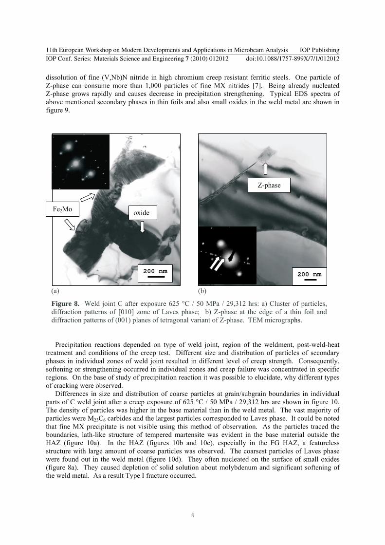
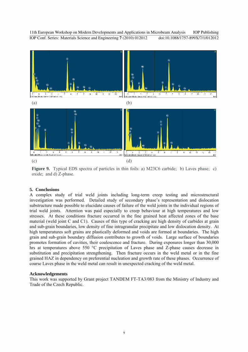
dissolution of fine (V,Nb)N nitride in high chromium creep resistant ferritic steels. One particle of Z-phase can consume more than 1,000 particles of fine MX nitrides [7]. Being already nucleated Z-phase grows rapidly and causes decrease in precipitation strengthening. Typical EDS spectra of above mentioned secondary phases in thin foils and also small oxides in the weld metal are shown in figure 9.
(a) (b)
Figure 8. Weld joint C after exposure 625 °C / 50 MPa / 29,312 hrs: a) Cluster of particles, diffraction patterns of [010] zone of Laves phase; b) Z-phase at the edge of a thin foil and diffraction patterns of (001) planes of tetragonal variant of Z-phase. TEM micrographs.
Precipitation reactions depended on type of weld joint, region of the weldment, post-weld-heat treatment and conditions of the creep test. Different size and distribution of particles of secondary phases in individual zones of weld joint resulted in different level of creep strength. Consequently, softening or strengthening occurred in individual zones and creep failure was concentrated in specific regions. On the base of study of precipitation reaction it was possible to elucidate, why different types of cracking were observed.
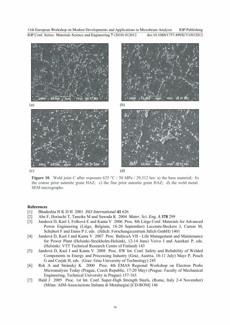
Differences in size and distribution of coarse particles at grain/subgrain boundaries in individual parts of C weld joint after a creep exposure of 625 °C / 50 MPa / 29,312 hrs are shown in figure 10. The density of particles was higher in the base material than in the weld metal. The vast majority of particles were M23C6 carbides and the largest particles corresponded to Laves phase. It could be noted that fine MX precipitate is not visible using this method of observation. As the particles traced the boundaries, lath-like structure of tempered martensite was evident in the base material outside the HAZ (figure 10a). In the HAZ (figures 10b and 10c), especially in the FG HAZ, a featureless structure with large amount of coarse particles was observed. The coarsest particles of Laves phase were found out in the weld metal (figure 10d). They often nucleated on the surface of small oxides (figure 8a). They caused depletion of solid solution about molybdenum and significant softening of the weld metal. As a result Type I fracture occurred.
200 nm
oxide Fe2Mo
Z-phase
200 nm
11th European Workshop on Modern Developments and Applications in Microbeam Analysis IOP PublishingIOP Conf. Series: Materials Science and Engineering 7 (2010) 012012 doi:10.1088/1757-899X/7/1/012012
8
(a) (b)
(c) (d)
Figure 9. Typical EDS spectra of particles in thin foils: a) M23C6 carbide; b) Laves phase; c) oxide; and d) Z-phase.
5. Conclusions A complex study of trial weld joints including long-term creep testing and microstructural investigation was performed. Detailed study of secondary phase’s representation and dislocation substructure made possible to elucidate causes of failure of the weld joints in the individual regions of trial weld joints. Attention was paid especially to creep behaviour at high temperatures and low stresses. At these conditions fracture occurred in the fine grained heat affected zones of the base material (weld joint C and C1). Causes of this type of cracking are high density of carbides at grain and sub-grain boundaries, low density of fine intragranular precipitate and low dislocation density. At high temperatures soft grains are plastically deformed and voids are formed at boundaries. The high grain and sub-grain boundary diffusion contributes to growth of voids. Large surface of boundaries promotes formation of cavities, their coalescence and fracture. During exposures longer than 30,000 hrs at temperatures above 550 °C precipitation of Laves phase and Z-phase causes decrease in substitution and precipitation strengthening. Then fracture occurs in the weld metal or in the fine grained HAZ in dependency on preferential nucleation and growth rate of these phases. Occurrence of coarse Laves phase in the weld metal can result in unexpected cracking of the weld metal.
Acknowledgements This work was supported by Grant project TANDEM FT-TA3/083 from the Ministry of Industry and Trade of the Czech Republic.
11th European Workshop on Modern Developments and Applications in Microbeam Analysis IOP PublishingIOP Conf. Series: Materials Science and Engineering 7 (2010) 012012 doi:10.1088/1757-899X/7/1/012012
9
(a)
(b)
(c)
(d)
Figure 10. Weld joint C after exposure 625 °C / 50 MPa / 29,312 hrs: a) the base material; b) the coarse prior autenite grain HAZ; c) the fine prior autenite grain HAZ; d) the weld metal. SEM micrographs.
References [1] Bhadeshia H K D H 2001 ISIJ International 41 626 [2] Abe F, Horiuchi T, Taneike M and Sawada K 2004 Mater. Sci. Eng. A 378 299 [3] Jandová D, Kasl J, Folková E and Kanta V 2006 Proc. 8th Liège Conf. Materials for Advanced
Power Engineering (Liège, Belgium, 18-20 September) Lecomte-Beckers J, Carton M, Schubert F and Ennis P J, eds. (Jülich: Forschungzcentrum Jülich GmbH) 1401
[4] Jandová D, Kasl J and Kanta V 2007 Proc. BalticaA VII - Life Management and Maintenance for Power Plant (Helsinki-Stockholm-Helsinki, 12-14 June) Veivo J and Auerkari P, eds. (Helsinki: VTT Technical Research Centre of Finland) 143
[5] Jandová D, Kasl J and Kanta V 2008 Proc. IIW Int. Conf. Safety and Reliability of Welded Components in Energy and Processing Industry (Graz, Austria, 10-11 July) Mayr P, Posch G and Cerjak H, eds. (Graz: Graz University of Technology) 245
[6] Rek A and Stránský K 2000 Proc. 4th EMAS Regional Workshop on Electron Probe Microanalysis Today (Prague, Czech Republic, 17-20 May) (Prague: Faculty of Mechanical Engineering, Technical University in Prague) 157-163
[7] Hald J 2005 Proc. 1st Int. Conf. Super-High Strength Steels, (Rome, Italy 2-4 November) (Milan: AIM-Associazione Italiana di Metalurgia) [CD-ROM] 146
11th European Workshop on Modern Developments and Applications in Microbeam Analysis IOP PublishingIOP Conf. Series: Materials Science and Engineering 7 (2010) 012012 doi:10.1088/1757-899X/7/1/012012
10