Embed Size (px)
Citation preview

Electronic Acknowledgement Receipt
43984229EFS ID:
Application Number:
Confirmation Number: 8399
PCT/US21/54122 International Application Number:
Title of Invention:SYSTEMS, DEVICES, AND METHODS FOR MULTISOURCE VOLUMETRIC SPECTRAL COMPUTED TOMOGRAPHY
First Named Inventor/Applicant Name: The University of North Carolina at Chapel Hill
Customer Number: 25297
Correspondence Address:
Jeffrey L. Wilson
-
3015 Carrington Mill Blvd, Suite 550
-
Morrisville NC 27560
US 9194938000
Application Type: International Application (PCT) for filing in the US receiving office
Time Stamp: 12:58:35
Filing Date:
Receipt Date: 08-OCT-2021
Attorney Docket Number: 421/170/31 PCT
Filer Authorized By: Jeffrey L. Wilson
Filer: Jeffrey L. Wilson/Bronwyn Tucker
Patent Number:
Payment information:

Submitted with Payment yes
Payment was successfully received in RAM 3297$
Payment Type CARD
RAM confirmation Number E202108C58571655
Deposit Account
Authorized User
The Director of the USPTO is hereby authorized to charge indicated fees and credit any overpayment as follows:
File Listing:
Document
NumberDocument Description File Name
File Size(Bytes)/
Message Digest
Multi
Part /.zip
Pages
(if appl.)
1 ZIP 42117031PCT.zip
120248
yes42ba5f9376d9c7efb57132916ab24817a65
9120e
Multipart Description/PDF files in .zip description
Document Description Start End
fees.pdf 1 1
pct101.pdf 1 4
Warnings:
Information:
2 421-170-31_PCT_PAT_APP.pdf
275939
yes 57fc1d62e8e381204e0d7d377a1751f5b134c
83566
Multipart Description/PDF files in .zip description
Document Description Start End
Specification 1 45
Claims 46 56
Abstract 57 57
Warnings:
Information:

3 Drawings-only black and white line drawings
421-170-31_PCT_FIGS_FINAL.pdf
5435769
no 254a63d12ada8685396f466075cc4b7e6ebe5
3e205
Warnings:
Information:
4 Fee Worksheet (SB06) fee-info.pdf
47108
no 22c0f89f8eb54971b2b901013ef4ac78be50d
b262
Warnings:
Information:
Total Files Size (in bytes): 6006064
This Acknowledgement Receipt evidences receipt on the noted date by the USPTO of the indicated documents,
characterized by the applicant, and including page counts, where applicable. It serves as evidence of receipt similar to a
Post Card, as described in MPEP 503.
New Applications Under 35 U.S.C. 111
If a new application is being filed and the application includes the necessary components for a filing date (see 37 CFR
1.53(b)-(d) and MPEP 506), a Filing Receipt (37 CFR 1.54) will be issued in due course and the date shown on this
Acknowledgement Receipt will establish the filing date of the application.
National Stage of an International Application under 35 U.S.C. 371
If a timely submission to enter the national stage of an international application is compliant with the conditions of 35
U.S.C. 371 and other applicable requirements a Form PCT/DO/EO/903 indicating acceptance of the application as a
national stage submission under 35 U.S.C. 371 will be issued in addition to the Filing Receipt, in due course.
New International Application Filed with the USPTO as a Receiving Office
If a new international application is being filed and the international application includes the necessary components for
an international filing date (see PCT Article 11 and MPEP 1810), a Notification of the International Application Number
and of the International Filing Date (Form PCT/RO/105) will be issued in due course, subject to prescriptions concerning
national security, and the date shown on this Acknowledgement Receipt will establish the international filing date of
the application.

421-170-31-PCT1/4
PCT REQUEST(Original in Electronic Form)
0 For receiving Office use only
0-1 International Application No.
0-2 International Filing Date
0-3 Name of receiving Office and "PCTInternational Application"
0-4 Form PCT/RO/101 PCT Request
0-4-1 Prepared Using ePCT-Filing for data package downloadVersion 4.8.010 MT/FOP 20211005/1.1
0-5 PetitionThe undersigned requests that the present international application be processed according to the Patent Cooperation Treaty
0-6 Receiving Office (specified by theapplicant)
United States Patent and Trademark Office (USPTO) (RO/US)
0-7 Applicant's or agent's file reference 421-170-31-PCTI Title of Invention SYSTEMS, DEVICES, AND METHODS FOR MULTISOURCE
VOLUMETRIC SPECTRAL COMPUTED TOMOGRAPHYII ApplicantII-1 This person is Applicant onlyII-2 Applicant for All designated StatesII-4 Name THE UNIVERSITY OF NORTH CAROLINA AT CHAPEL HILLII-5 Address Office of Technology Commercialization
109 Church StreetChapel Hill, North Carolina 27516United States of America
II-6 State of nationality USII-7 State of residence USIII-1 Applicant and/or inventorIII-1-1 This person is Inventor onlyIII-1-3 Inventor for All designated StatesIII-1-4 Name (LAST, First) ZHOU, Otto Z.III-1-5 Address 312 Silver Creek Trail
Chapel Hill, North Carolina 27514United States of America
III-2 Applicant and/or inventorIII-2-1 This person is Inventor onlyIII-2-3 Inventor for All designated StatesIII-2-4 Name (LAST, First) LU, JianpingIII-2-5 Address 109 Glen Haven Drive
Chapel Hill, North Carolina 27516United States of America
Preview generated on 08 October 2021 at 18:11 CEST

421-170-31-PCT2/4
PCT REQUEST(Original in Electronic Form)
III-3 Applicant and/or inventorIII-3-1 This person is Inventor onlyIII-3-3 Inventor for All designated StatesIII-3-4 Name (LAST, First) INSCOE, ChristinaIII-3-5 Address 308 Onondaga Court
Holly Springs, North Carolina 27540United States of America
III-4 Applicant and/or inventorIII-4-1 This person is Inventor onlyIII-4-3 Inventor for All designated StatesIII-4-4 Name (LAST, First) LEE, Yueh ZenasIII-4-5 Address 6 Midstream Court
Chapel Hill, North Carolina 27517United States of America
III-5 Applicant and/or inventorIII-5-1 This person is Inventor onlyIII-5-3 Inventor for All designated StatesIII-5-4 Name (LAST, First) LI, BoyuanIII-5-5 Address 201 S Elliott Road, Apt. 325
Chapel Hill, North Carolina 27514United States of America
IV-1 Agent or common representative; oraddress for correspondenceThe person identified below is hereby/has been appointed to act on behalf ofthe applicant(s) before the competentInternational Authorities as:
Agent
IV-1-1 Name (LAST, First) WILSON, Jeffrey L.IV-1-2 Address JENKINS, WILSON, TAYLOR & HUNT, P.A.
3015 CARRINGTON MILL BOULEVARDSUITE 550Morrisville, North Carolina 27560United States of America
IV-1-3 Telephone No. 919-493-8000IV-1-5 e-mail [email protected](a) E-mail authorization
The receiving Office, the InternationalSearching Authority, the InternationalBureau and the International PreliminaryExamining Authority are authorized touse this e-mail address, if the Office orAuthority so wishes, to send notificationsissued in respect of this internationalapplication:
exclusively in electronic form (no paper notifications will besent)
IV-1-6 Agent's registration No. 36,058
Preview generated on 08 October 2021 at 18:11 CEST

421-170-31-PCT3/4
PCT REQUEST(Original in Electronic Form)
V DESIGNATIONSV-1 The filing of this request constitutes under Rule 4.9(a), the designation of all Contracting States bound by the PCT on
the international filing date, for the grant of every kind of protection available and, where applicable, for the grant ofboth regional and national patents.
VI-1 Priority claim of earlier nationalapplication
VI-1-1 Filing date 09 October 2020 (09.10.2020)VI-1-2 Number 63/089,875VI-1-3 Country or Member of WTO USVI-2 Priority document request
The receiving Office is requested toprepare and transmit to the InternationalBureau a certified copy of the earlierapplication(s) identified above as item(s):
VI-1
VI-3 Incorporation by reference :
where an element of the international application referred to in Article 11(1)(iii)(d) or (e) or a part of the description, claims ordrawings referred to in Rule 20.5(a), or an element or part of the description, claims or drawings referred to in Rule 20.5bis(a)is not otherwise contained in this international application but is completely contained in an earlier application whose priority isclaimed on the date on which one or more elements referred to in Article 11(1)(iii) were first received by the receiving Office,that element or part is, subject to confirmation under Rule 20.6, incorporated by reference in this international application forthe purposes of Rule 20.6.
VII-1 International Searching AuthorityChosen
Korean Intellectual Property Office (ISA/KR)
VIII Declarations Number of declarationsVIII-1 Declaration as to the identity of the
inventor-
VIII-2 Declaration as to the applicant'sentitlement, as at the international filingdate, to apply for and be granted a patent
-
VIII-3 Declaration as to the applicant'sentitlement, as at the international filingdate, to claim the priority of the earlierapplication
-
VIII-4 Declaration of inventorship (only for thepurposes of the designation of the UnitedStates of America)
-
VIII-5 Declaration as to non-prejudicialdisclosures or exceptions to lack ofnovelty
-
IX Check list Number of sheets Electronic file(s) attachedIX-1 Request (including declaration sheets) 4 ✓IX-2 Description 45 ✓IX-3 Claims 11 ✓IX-4 Abstract 1 ✓IX-5 Drawings 25 ✓IX-6a Sequence listing part of the description
(also to be used for the purposes ofinternational search)
- -
IX-7 TOTAL 86
Preview generated on 08 October 2021 at 18:11 CEST

421-170-31-PCT4/4
PCT REQUEST(Original in Electronic Form)
Accompanying Items Paper document(s) attached Electronic file(s) attachedIX-8 Fee calculation sheet - ✓IX-20 Figure of the drawings which should
accompany the abstract1
IX-21 Language of filing of the internationalapplication
English
X-1 Signature of applicant, agent orcommon representative
/Jeffrey L. Wilson, Reg. No. 36,058/
X-1-1 Name (LAST, First) WILSON, Jeffrey L.X-1-3 Capacity (if such capacity is not obvious
from reading the request)Agent
FOR RECEIVING OFFICE USE ONLY
10-1 Date of actual receipt of the purportedinternational application
10-210-2-110-2-2
Drawings:ReceivedNot received
10-3 Corrected date of actual receipt dueto later but timely received papers ordrawings completing the purportedinternational application
10-4 Date of timely receipt of the requiredcorrections under PCT Article 11(2)
10-5 International Searching Authority ISA/KR10-6 Transmittal of search copy delayed
until search fee is paid
FOR INTERNATIONAL BUREAU USE ONLY
11-1 Date of receipt of the record copy bythe International Bureau
Preview generated on 08 October 2021 at 18:11 CEST

421-170-31-PCT1/1
PCT (ANNEX - FEE CALCULATION SHEET)(Original in Electronic Form)
(This sheet is not part of and does not count as a sheet of the international application)
0 For receiving Office use only0-1 International Application No.0-2 Date stamp of the receiving Office
0-4 Form PCT/RO/101 (Annex)PCT Fee Calculation Sheet
0-4-1 Prepared Using ePCT-Filing for data package downloadVersion 4.8.010 MT/FOP 20211005/1.1
0-9 Applicant's or agent's file reference 421-170-31-PCT2 Applicant THE UNIVERSITY OF NORTH CAROLINA AT CHAPEL HILL12 Calculation of prescribed fees Fee amount/multiplier Total amounts (USD)
12-1 Transmittal fee T ➪ 13012-2-1 Search fee S ➪ 103612-2-2 International search to be carried out by KR12-3 International filing fee
(first 30 sheets) i1 145312-4 Remaining sheets 5612-5 Additional amount (X) 1612-6 Total additional amount i2 89612-7 i1 + i2 = i 2349
12-12 Electronic Filing reduction (Image) R -21812-13 Total International filing fee (i-R) I ➪ 213112-17 Fee for restoration of priority rights RP
Number of requests for restoration ofpriority rights
0
Total amount of fees for restoration ofpriority rights
12-19 TOTAL FEES PAYABLE (T+S+I+P+RP) ➪ 329712-21 Mode of payment Credit card12-22 Payment contact [email protected]
Attorney Docket 421/170/31 PCT
-1-
TITLE
SYSTEMS, DEVICES, AND METHODS FOR MULTISOURCE
VOLUMETRIC SPECTRAL COMPUTED TOMOGRAPHY
CROSS-REFERENCE TO RELATED APPLICATIONS
This application claims the benefit or and priority to U.S. Provisional
Patent Application Serial No. 63/089,875, which was filed on October 9, 2020,
the disclosure of which is incorporated by reference herein in its entirety.
TECHNICAL FIELD
The subject matter disclosed herein relates generally to computed
tomography (CT) imaging. More particularly, the subject matter disclosed
herein relates to multisource volumetric spectral CT imaging.
BACKGROUND
Since its introduction about fifty years ago, computed tomography (CT)
has experienced tremendous improvement in the imaging technology and
growth in its clinical applications. In recent years cone-beam CT (CBCT), as
a volumetric 3D imaging modality, has found growing applications in areas
including on-board image guidance for radiation therapy (IGRT),
intraoperative imaging for surgical guidance, maxillofacial radiology, and
extremity imaging.
In CBCT the radiation from an x-ray source is collimated to a conical
geometry to cover a large region-of interest (ROI). Using a large-area flat-
panel detector (FPD) an entire volumetric dataset is acquired with a single
rotation of the x-ray source-detector pair in an open gantry, eliminating the
need for patient translation in regular fan-beam CT. Additional advantages of
CBCT compared to fan-beam CT include a smaller footprint, mobility, and
lower radiation dose. This makes CBCT particularly attractive for image-
guided therapies. On-board CBCT is being used in modern radiation therapy
for patient setup, dose verification, and adaptive re-planning. C-arm based
CBCT brought 3D imaging capability to the operating suite, resulting in a major
advancement in intraoperative imaging.
Attorney Docket 421/170/31 PCT
-2-
CBCT provides a three-dimensional (3D) representation of the
maxillofacial region of the skull and dentition with minimal distortion and
improved image sharpness at relatively low cost and low radiation dose. It has
found wide applications in dentistry since it was approved by the FDA 20 years
ago. Examples of clinical tasks performed by CBCT include dental implant and
orthodontic treatment planning, and evaluation of endodontic and pathological
conditions.
CBCT has several known limitations including: (1) high scatter
radiation, (2) strong metal-induced imaging artifacts, and (3) various cone-
beam image artifacts that degrade the image quality and compromise its
diagnostic accuracy. .
The presence of strong metal-induced imaging artifacts in and/or on
anatomical structures to be imaged, however, has represented a significant
limitation in the use of CBCT. The strong x-ray attenuation caused by the
presence of common metal structures, especially in dentistry application,
where it is common to encounter metallic dental restorations and implants,
results in beam hardening and photon starvation in all known CBCT-based
imaging techniques and systems. This phenomenon leads to imaging artifacts
in the form of, for example, streaks and halos, in the reconstructed 3D images
produced using CBCT. Such metal-induced imaging artifacts degrade image
quality, compromise diagnostic accuracy, and make dental CBCT wholly
ineffective, for example, in postoperative evaluation of the osseointegration of
implants. Various postprocessing techniques are known to have been
investigated for metal artifact reduction (MAR), however, the results of these
algorithms have proven to be generally unworkable for their intended
purposes.
The divergent cone beam also introduces aliasing artifacts and
truncation errors. Because of the high scattered radiation and image artifacts
CBCT is known to underestimate the CT Hounsfield Unit (HU).
Virtual monoenergetic images (VMI) synthesized using dual-energy CT
(DECT) datasets at high virtual monoenergetic energies are known to reduce
metal artifacts, particularly for small metallic objects such as dental implants.

Attorney Docket 421/170/31 PCT
-3-
With images obtained at two different polychromatic energy spectra,
DECT enables more quantitative analysis including determination of the
photoelectric and Compton contributions to the attenuation coefficient,
synthesizing virtual monoenergetic images (VMI), calculation of the effective
atomic number and effective electron density, and more accurate
determination of the CT Hounsfield Unit, without increasing the x-ray exposure
levels for patients. Dual energy imaging is also used in other x-ray imaging
modalities, including contrast enhanced dual energy tomosynthesis.
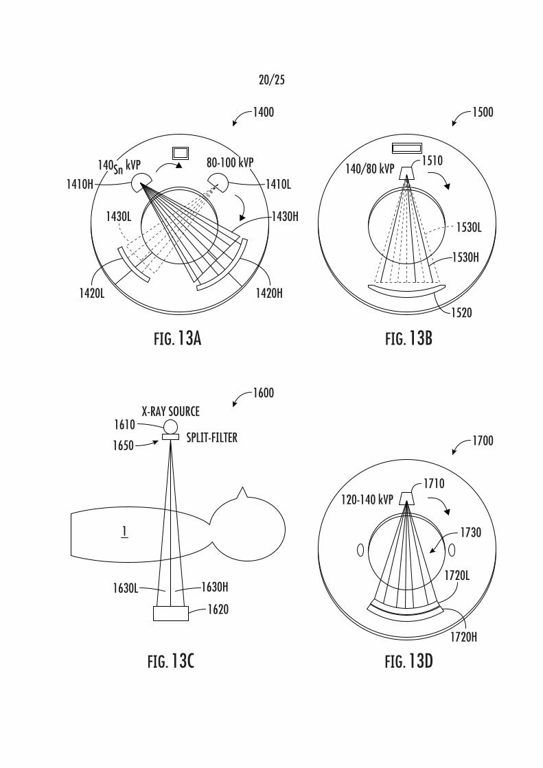
Several technologies have been developed for DECT imaging,
examples of which are shown in FIGS. 13A-D. In FIG. 13A, a dual source CT
(DSCT) system uses two x-ray tubes operating at different tube voltages (kVp)
and two energy integrating detectors (EIDs). In the system of FIG. 13B, rapid
kVp switching of a single x-ray tube between low energy (LE) and high energy
(HE) is used to produce two polychromatic spectra. In the system of FIG. 13C,
a split-filter CT is used, which has a single x-ray source and two adjacent
filters. The system of FIG. 13D is a CT imaging system with an energy
sensitivity detector.
However, each of these dual energy imaging systems suffers from a
major shortcoming associated with the significantly increased cost of the
equipment needed to build and operate such DECT systems. In addition, each
of the example known DECT systems shown in FIGS. 13A-D have various
technical limitations associated therewith. In DSCT, the LE and HE spectra
can be generated simultaneously, with independent control of the tube current
and kVp to balance the radiation dose and for anatomical dose modulation,
and can be further optimized by introducing individual filters. However, in such
known DECT systems using two x-ray tubes and detectors, as well as other
necessary additional electronics devices, such systems are known to be
significantly more expensive in comparison to a single energy CT system.
Rapid kVp switching, on the order of ~60kV is also known to require
the installation and usage of expensive electronics to modulate power levels
to such a degree. The kVp profile resultant from such rapid switching also
deviates substantially from the ideal step function for CT imaging, which
results in the introduction of uncertainty and/or error in quantitative analysis.

Attorney Docket 421/170/31 PCT
-4-
By using common filtration, the LE and HE spectra have substantially more
overlap compared to DSCT, which causes a degradation of accuracy for
materials decomposition.
Using currently known technology, there exists a difficulty in rapidly
changing the tube current simultaneously with changes to the kVp, which
leads to a much lower photon flux and a higher imaging noise in the LE
spectra, as compared to the HE spectra. In addition, anatomical dose
modulation for patient radiation dose reduction is challenging. In split-filter
DECT, each beam covers only half of the detector width in the axial direction
and has a smaller energy separation than using DSCT. Thus, it is necessary
to significantly increase the X-ray output to compensate for the additional
attenuation from the use of such spectral filters. Increased spectral overlap
between LE and HE spectra also reduces efficiency and precision for tissue
differentiation. Although there have been significant advances in the
development of energy-sensitive detectors, such as photon counting
detectors, costs associated with such detectors are significantly higher than
conventionally used energy integrating detectors and such detectors are also
known to suffer from photon pile up and cross talk.
Most of the known DECT systems are based on fan-beam geometry
and DECT systems are not commonly available in dental clinics due to the
high cost associated therewith.A dual energy CBCT (DE-CBCT) was recently
introduced for dental imaging which requires both fast kVp switching and
spectral filtration. Along with the increased cost, high scattered radiation was
still present due to the large cone angle.
In order to address the disadvantages known from the prior art imaging
techniques, a new cone beam CT imaging system and method are disclosed
herein.
SUMMARY
In accordance with this disclosure, a volumetric spectral computed
tomography (CT) imaging device is provided, the device comprising: an x-ray
source array comprising M numbers of spatially distributed x-ray focal spots;
an x-ray beam collimator attached to the x-ray source array, wherein the x-ray

Attorney Docket 421/170/31 PCT
-5-
beam collimator contains an array of apertures, each configured to confine the
x-ray radiation from a corresponding x-ray focal spot to illuminate a
corresponding segment of an object to be imaged; a digital area x-ray detector
configured to detect x-ray radiation and form an x-ray image of the object
being imaged, wherein the digital area x-ray detector is positioned on an
opposite side of the object with respect to the x-ray source array; a gantry
configured to rotate the x-ray source array and the digital area x-ray detector
around the object, wherein the spatially distributed x-ray focal spots are
substantially aligned either along a direction of a rotation axis of the gantry or
along a direction of rotation of the gantry; an electronic control unit that
activates the M numbers of x-ray focal spots to scan the object N times as the
gantry rotates around the object; and one or more processing systems
configured to process the raw N x M projection images to reconstruct a
volumetric CT image of the object.
In some embodiments, radiation from each focal spot is configured to
be filtered by a corresponding spectral filter.
In some embodiments, only a subset of the focal spots is used to
acquire projection images for CT image reconstruction.
In some embodiments, wherein the x-ray focal spots are divided into a
first set and a second set; wherein x-ray beams from the focal spots in the first
set are filtered by a first filter material(s) configured to yield a spectrum with a
first mean x-ray photon energy, and x-ray beams in the second set are filtered
by a second filter material(s) configured to yield a spectrum with a second
mean x-ray photon energy, the first mean x-ray photon energy being different
from the second mean x-ray photon energy; and wherein two sets of projection
images acquired from the first set and the second set is sufficient to
reconstruct the volumetric CT image of the whole object at each distinct x-ray
spectrum.
In some embodiments, the first mean x-ray photon energy is lower than
the second mean x-ray photon energy; and the two sets of projection images
captured using the first mean x-ray photon energy and the second mean x-ray
photon energy are processed to obtain the dual energy CT images of the
object.
Attorney Docket 421/170/31 PCT
-6-
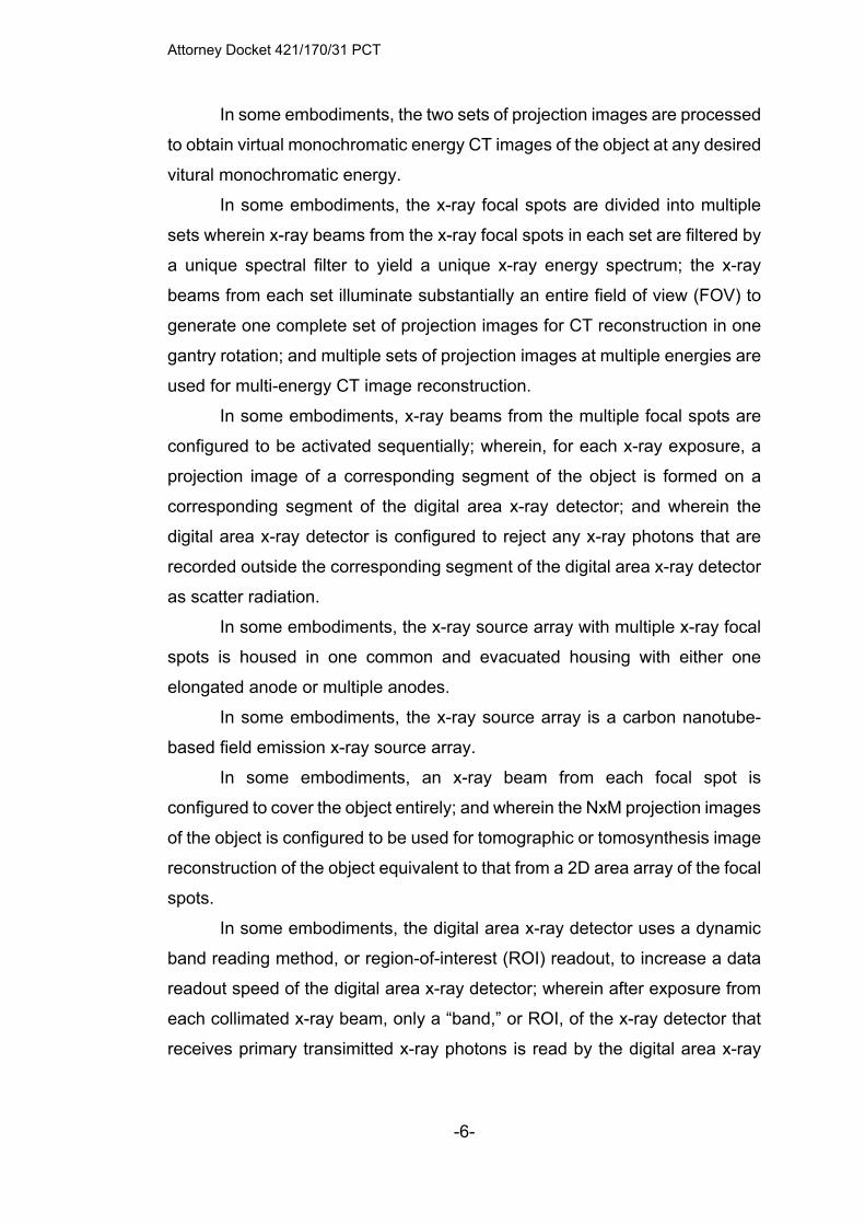
In some embodiments, the two sets of projection images are processed
to obtain virtual monochromatic energy CT images of the object at any desired
vitural monochromatic energy.
In some embodiments, the x-ray focal spots are divided into multiple
sets wherein x-ray beams from the x-ray focal spots in each set are filtered by
a unique spectral filter to yield a unique x-ray energy spectrum; the x-ray
beams from each set illuminate substantially an entire field of view (FOV) to
generate one complete set of projection images for CT reconstruction in one
gantry rotation; and multiple sets of projection images at multiple energies are
used for multi-energy CT image reconstruction.
In some embodiments, x-ray beams from the multiple focal spots are
configured to be activated sequentially; wherein, for each x-ray exposure, a
projection image of a corresponding segment of the object is formed on a
corresponding segment of the digital area x-ray detector; and wherein the
digital area x-ray detector is configured to reject any x-ray photons that are
recorded outside the corresponding segment of the digital area x-ray detector
as scatter radiation.
In some embodiments, the x-ray source array with multiple x-ray focal
spots is housed in one common and evacuated housing with either one
elongated anode or multiple anodes.
In some embodiments, the x-ray source array is a carbon nanotube-
based field emission x-ray source array.
In some embodiments, an x-ray beam from each focal spot is
configured to cover the object entirely; and wherein the NxM projection images
of the object is configured to be used for tomographic or tomosynthesis image
reconstruction of the object equivalent to that from a 2D area array of the focal
spots.
In some embodiments, the digital area x-ray detector uses a dynamic
band reading method, or region-of-interest (ROI) readout, to increase a data
readout speed of the digital area x-ray detector; wherein after exposure from
each collimated x-ray beam, only a “band,” or ROI, of the x-ray detector that
receives primary transimitted x-ray photons is read by the digital area x-ray

Attorney Docket 421/170/31 PCT
-7-
detector instead of the entire detector which the amount of the data read and
transmitted.
In some embodiments of the imaging device, the digital area x-ray
detector uses a dynamic region-of-interest (ROI) readout method, to increase
a data readout speed of the digital area x-ray detector; and, after exposure
from each collimated x-ray beam, only a “band,” or ROI, of the digital area x-
ray detector that receives primary transimitted x-ray photons is read by the
digital area x-ray detector instead of the entire detector.
In some embodiments, a precise location of each detector band
associated with each x-ray source (focal spot) is pre-determined from the
configuration of the imaging system, wherein the software automatically
determines a region of the digital area x-ray detector to be read for each
specific x-ray exposure.
In some embodiments, the NxM projection images are treated as one
complete data set for volumetric CT reconstruction using a model-based
iterative reconstruction method, wherein locations of the x-ray focal spots for
the NxM projection images are predetermined during system calibration.
In some embodiments, the reconstructed CT images are stored in a
Digital Imaging and Communications in Medicine (DICOM) format and can be
viewed, analyzed and stored using third party software packages.
In another aspect, a volumetric spectral computed tomography imaging
device with increased contrast resolution and reduced metal-induced imaging
artifacts is provided, the device comprising: an x-ray source array comprising
M numbers of spatially distributed x-ray focal spots enclosed in a same
evacuated housing, wherein the spatially distributed focal spots are divided
into two groups, wherein x-ray radiation from each group is filtered by a
corresponding spectral filter material to produce a distinct energy spectrum;
an x-ray beam confining device attached to the x-ray source array, wherein
the x-ray beam confining device comprises: an array of apertures, each
configured to confine x-ray radiation from a corresponding x-ray focal spot to
form a fan beam shape with a narrow cone angle that illuminates a
corresponding segment of an object, wherein radiation from each group of
focal spots collectively cover an entire field-of view (FOV); a digital area x-ray

Attorney Docket 421/170/31 PCT
-8-
detector; a gantry configured to rotate the x-ray source array and the digital
area x-ray detector around the object; an electronic control unit configured to
activate the M numbers of x-ray focal spots, one or more beams at a time, to
scan across the object N times as the gantry rotates around the object, and
configured to read out an image recorded on a corresponding area of the
digital area x-ray detector and configured to reject scattered x-ray photons
received outside an area of the digital area x-ray detector for each x-ray
exposure; and one or more processing systems configured to process the
projection images formed by radiation exposure from each group of focal
spots to reconstruct two volumetric CT image datasets of the object, each
volumetric CT image dataset taken at a different mean x-ray photon energy,
the one or more processing systems being further configured to synthesize
virtual monoenergetic CT image datasets at desired energy levels with
reduced metal-induced imaging artifacts; wherein the spatially distributed x-
ray focal spots are substantially aligned along a direction of the gantry rotation
axis.
In another aspect, a method for performing volumetric spectral
computed tomography (CT) imaging of an object is provided, the method
comprising: providing a volumetric spectral computed tomography imaging
device comprising: an x-ray source array comprising M numbers of spatially
distributed x-ray focal spots; an x-ray beam confiner attached to the x-ray
source array, wherein the x-ray beam confiner contains an array of apertures,
each configured to confine the x-ray radiation from a corresponding x-ray focal
spot to a fan beam having a narrow cone angle that illuminates a
corresponding segment of the object to be imaged; a digital area x-ray
detector configured to detect x-ray radiation and form an x-ray image of the
object being imaged, wherein the digital area x-ray detector is positioned on
an opposite side of the object with respect to the x-ray source array; and a
gantry configured to rotate the x-ray source array and the digital area x-ray
detector around the object, wherein the spatially distributed x-ray focal spots
are substantially aligned along a direction of a rotation axis of the gantry;
activating the M numbers of x-ray focal spots to scan the object N times;
rotating the gantry around the object while the x-ray focal spots are activated;

Attorney Docket 421/170/31 PCT
-9-
filtering radiation from each focal spot by a corresponding spectral filter; and
processing, using one or more processors, N x M projection images to
reconstruct a volumetric CT image of the object.
In some embodiments, the method futher comprises using only a
subset of the focal spots to acquire projection images for CT image
reconstruction.
In some embodiments, the x-ray focal spots are divided into a first set
and a second set; wherein x-ray beams from the focal spots in the first set are
filtered by a first filter material configured to yield a spectrum with a first mean
x-ray photon energy, and x-ray beams in the second set are filtered by a
second filter material configured to yield a spectrum with a second mean x-
ray photon energy, the first mean x-ray photon energy being different from the
second mean x-ray photon energy; and wherein two sets of projection images
acquired from the first set and the second set is sufficient to reconstruct the
volumetric CT image of the whole object at each distinct x-ray spectrum.
In some embodiments, processing the N x M images comprises
processing images captured using the first mean x-ray photon energy and
images captured using the second mean x-ray photon energy to obtain a
single volumetric CT image of the object.
In some embodiments, the first mean x-ray photon energy is lower than
the second mean x-ray photon energy; and wherein the two sets of projection
images captured using the first mean x-ray photon energy and the second
mean x-ray photon energy are processed to obtain the dual energy CT images
of the object.
In some embodiments, the two sets of projection images are processed
to obtain one or more virtual monochromatic energy CT images of the object
at any desired energy.
In some embodiments, the x-ray focal spots are divided into multiple
sets wherein x-ray beams from the x-ray focal spots in each set are filtered by
a unique spectral filter to yield a unique x-ray energy spectrum; and wherein
the x-ray beams from each set illuminate substantially an entire field of view
(FOV) to generate one complete set of projection images for CT
reconstruction in one gantry rotation.

Attorney Docket 421/170/31 PCT
-10-
In some embodiments, the method further comprises sequentially
activating x-ray beams from the multiple focal spots; wherein, for each x-ray
exposure, a projection image of a corresponding segment of the object is
formed on a corresponding segment of the digital area x-ray detector; and
wherein the digital area x-ray detector is configured to reject any x-ray photons
that are recorded outside the corresponding segment of the digital area x-ray
detector as scatter radiation.
In some embodiments, the x-ray source array with multiple x-ray focal
spots is housed in one common and evacuated housing with either one
elongated anode or multiple anodes.
In some embodiments, the x-ray source array is a carbon nanotube-
based field emission x-ray source array.
In some embodiments, an x-ray beam from each focal spot is
configured to cover the object entirely; and the NxM projection images of the
object is configured to be used for tomographic or tomosynthesis image
reconstruction of the object equivalent to that from a 2D area array of the focal
spots.
In another aspect, a dual-energy computed tomography (CT) imaging
device is provided, the imaging device comprising: an x-ray generator
comprising an x-ray source, which has at least one cathode and at least one
anode and is configured to emit x-ray radiation from first and second focal
spots for imaging an object, and first and second spectral filters, wherein the
first spectral filter is configured to filter the x-ray radiation from the first focal
spot to produce low-energy (LE) x-ray radiation with a low mean energy, and
wherein the second spectral filter is configured to filter the x-ray radiation from
the second focal spot to produce high-energy (HE) x-ray radiation, the HE x-
ray radiation having a higher mean energy than the LE x-ray radiation; an x-
ray beam collimator that is configured to confine the LE x-ray radiation and
the HE x-ray radiation to substantially a same region of interest on, in, and/or
about the object; an x-ray detector configured to detect x-ray radiation and
form an x-ray image of the object, wherein the x-ray detector is positioned on
a different side of the object relative to the x-ray source; a gantry configured
to rotate the x-ray source and the x-ray detector around the object; a controller

Attorney Docket 421/170/31 PCT
-11-
that is configured to (1) activate the LE x-ray radiation and the HE x-ray
radiation multiple times in an alternating exposure pattern as the x-ray source
and the x-ray detector are rotated about the object, such that an LE projection
image of the object is recorded by the x-ray detector for each exposure of the
LE x-ray radiation and an HE projection image of the object is recorded by the
x-ray detector for each exposure of the HE x-ray radiation; and (2) activate
and program an exposure level of the LE x-ray radiation and an exposure level
of the HE x-ray radiation, wherein the exposure level of the LE x-ray radiation
is independent of the exposure level of the HE x-ray radiation; and one or
more processing systems configured to reconstruct dual-energy CT images of
the object using the LE projection images and the HE projection images.
In some embodiments, the at least one cathode of the x-ray source
comprises at least first and second cathodes, each of which is configured to
emit electrons in a form of an electron beam, wherein the at least one anode
is only one anode, wherein the first and second focal spots are on the anode,
wherein first cathode is positioned such that the electron beam emitted from
the first cathode is incident on the anode at the first focal spot, and wherein
the second cathode is positioned such that the electron beam emitted from
the second cathode is incident on the anode at the second focal spot.
In some embodiments, the at least one cathode of the x-ray source
comprises at least first and second cathodes, each of which is configured to
emit electrons in a form of an electron beam, and wherein the at least one
anode of the x-ray source comprises at least first and second anodes.
In some embodiments, the first and second anodes are connected to a
common electrical feedthrough.
In some embodiments, the imaging device comprises a device, which
is electrically connected to the first anode to reduce an electrical potential
between the first anode and the first cathode compared to an electrical
potential between the second anode and the second cathode when a same
electrical potential is applied to the x-ray generator through the electrical
feedthrough by a power supply.
In some embodiments, the device is an electrical resistor.
Attorney Docket 421/170/31 PCT
-12-
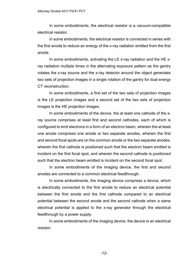
In some embodiments, the electrical resistor is a vacuum-compatible
electrical resistor.
In some embodiments, the electrical resistor is connected in series with
the first anode to reduce an energy of the x-ray radiation emitted from the first
anode.
In some embodiments, activating the LE x-ray radiation and the HE x-
ray radiation multiple times in the alternating exposure pattern as the gantry
rotates the x-ray source and the x-ray detector around the object generates
two sets of projection images in a single rotation of the gantry for dual energy
CT reconstruction.
In some embodiments, a first set of the two sets of projection images
is the LE projection images and a second set of the two sets of projection
images is the HE projection images.
In some embodiments of the device, the at least one cathode of the x-
ray source comprises at least first and second cathodes, each of which is
configured to emit electrons in a form of an electron beam, wherein the at least
one anode comprises one anode or two separate anodes, wherein the first
and second focal spots are on the common anode or the two separate anodes,
wherein the first cathode is positioned such that the electron beam emitted is
incident on the first focal spot, and wherein the second cathode is positioned
such that the electron beam emitted is incident on the second focal spot.
In some embodiments of the imaging device, the first and second
anodes are connected to a common electrical feedthrough.
In some embodiments, the imaging device comprises a device, which
is electrically connected to the first anode to reduce an electrical potential
between the first anode and the first cathode compared to an electrical
potential between the second anode and the second cathode when a same
electrical potential is applied to the x-ray generator through the electrical
feedthrough by a power supply.
In some embodiments of the imaging device, the device is an electrical
resistor.
Attorney Docket 421/170/31 PCT
-13-
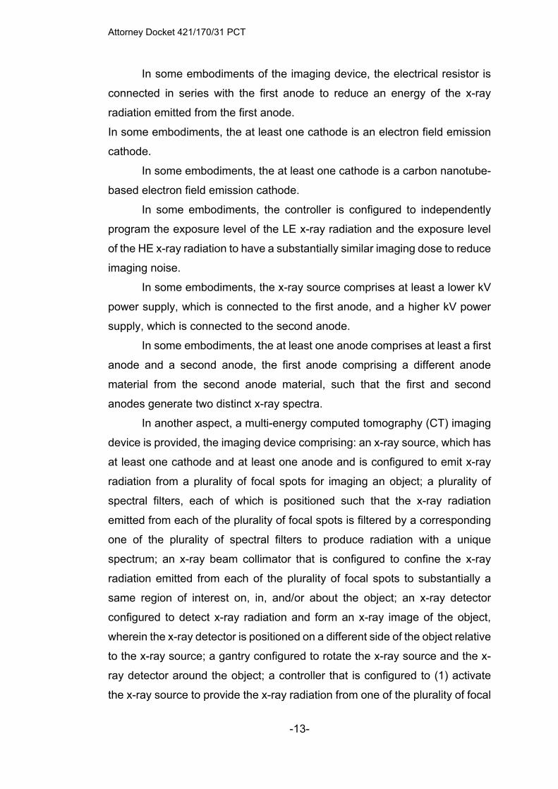
In some embodiments of the imaging device, the electrical resistor is
connected in series with the first anode to reduce an energy of the x-ray
radiation emitted from the first anode.
In some embodiments, the at least one cathode is an electron field emission
cathode.
In some embodiments, the at least one cathode is a carbon nanotube-
based electron field emission cathode.
In some embodiments, the controller is configured to independently
program the exposure level of the LE x-ray radiation and the exposure level
of the HE x-ray radiation to have a substantially similar imaging dose to reduce
imaging noise.
In some embodiments, the x-ray source comprises at least a lower kV
power supply, which is connected to the first anode, and a higher kV power
supply, which is connected to the second anode.
In some embodiments, the at least one anode comprises at least a first
anode and a second anode, the first anode comprising a different anode
material from the second anode material, such that the first and second
anodes generate two distinct x-ray spectra.
In another aspect, a multi-energy computed tomography (CT) imaging
device is provided, the imaging device comprising: an x-ray source, which has
at least one cathode and at least one anode and is configured to emit x-ray
radiation from a plurality of focal spots for imaging an object; a plurality of
spectral filters, each of which is positioned such that the x-ray radiation
emitted from each of the plurality of focal spots is filtered by a corresponding
one of the plurality of spectral filters to produce radiation with a unique
spectrum; an x-ray beam collimator that is configured to confine the x-ray
radiation emitted from each of the plurality of focal spots to substantially a
same region of interest on, in, and/or about the object; an x-ray detector
configured to detect x-ray radiation and form an x-ray image of the object,
wherein the x-ray detector is positioned on a different side of the object relative
to the x-ray source; a gantry configured to rotate the x-ray source and the x-
ray detector around the object; a controller that is configured to (1) activate
the x-ray source to provide the x-ray radiation from one of the plurality of focal

Attorney Docket 421/170/31 PCT
-14-
points multiple times in a sequential exposure pattern as the x-ray source and
the x-ray detector are rotated about the object, such that a projection image
of the object is recorded by the x-ray detector for each exposure of the x-ray
radiation; and (2) activate and program an exposure level of the x-ray
exposures from one or more of the plurality of focal spots sequentially,
wherein the exposure level of each of x-ray radiations is independent of others
of the x-ray radiations; and one or more processing systems configured to
reconstruct multi-energy CT images of the object using the projection images.
In some embodiments, the at least one cathode comprises a plurality
of electron field emission cathodes and the at least one anode comprises a
plurality of anodes.
In some embodiments, each anode of the plurality of anodes is
connected to an electrical resistor configured to adjust an electrical potential
between the anode to which the electrical resistor is connected and a
corresponding one of the plurality of cathodes.
In some embodiments, the electrical resistor is configured to adjust the
electrical potential from a common electrical potential provided from an anode
power supply to each of the plurality of anodes.
In some embodiments, the x-ray source comprises a plurality of
electrical potential inputs connected to a corresponding, or same, number of
the at least one anode.
In some embodiments, the x-ray source comprises, for each of the at
least one cathode, an electron beam focusing structure.
In some embodiments, the imaging device comprises a power supply
configured to supply an electrical potential to each of the at least one anode.
In some embodiments, the imaging device comprises an electrical
resistor that is connected in series between an anode of the at least one anode
and the power supply, the electrical resistor being configured to reduce the
electrical potential provided to the anode to which the electrical resistor is
connected.
In some embodiments, the controller is configured to vary a resistance
of the electrical resistor to vary the electrical potential provided to the anode
to which the electrical resistor is connected as a function of the resistance.

Attorney Docket 421/170/31 PCT
-15-
In some embodiments, the electron beam focusing structure for each
of the at least one cathode is configured such that the plurality of focal spots
have a substantially similar focal spot size while the electrical potential
between the anode, to which the electrical resistor is connected, and a
corresponding cathode of the at least one cathode is varied by the controller.
Although some of the aspects of the subject matter disclosed herein
have been stated hereinabove, and which are achieved in whole or in part by
the presently disclosed subject matter, other aspects will become evident as
the description proceeds when taken in connection with the accompanying
drawings as best described hereinbelow.
BRIEF DESCRIPTION OF THE DRAWINGS
FIG. 1A shows an example prior art cone-based computed tomography
(CBCT) imaging device.
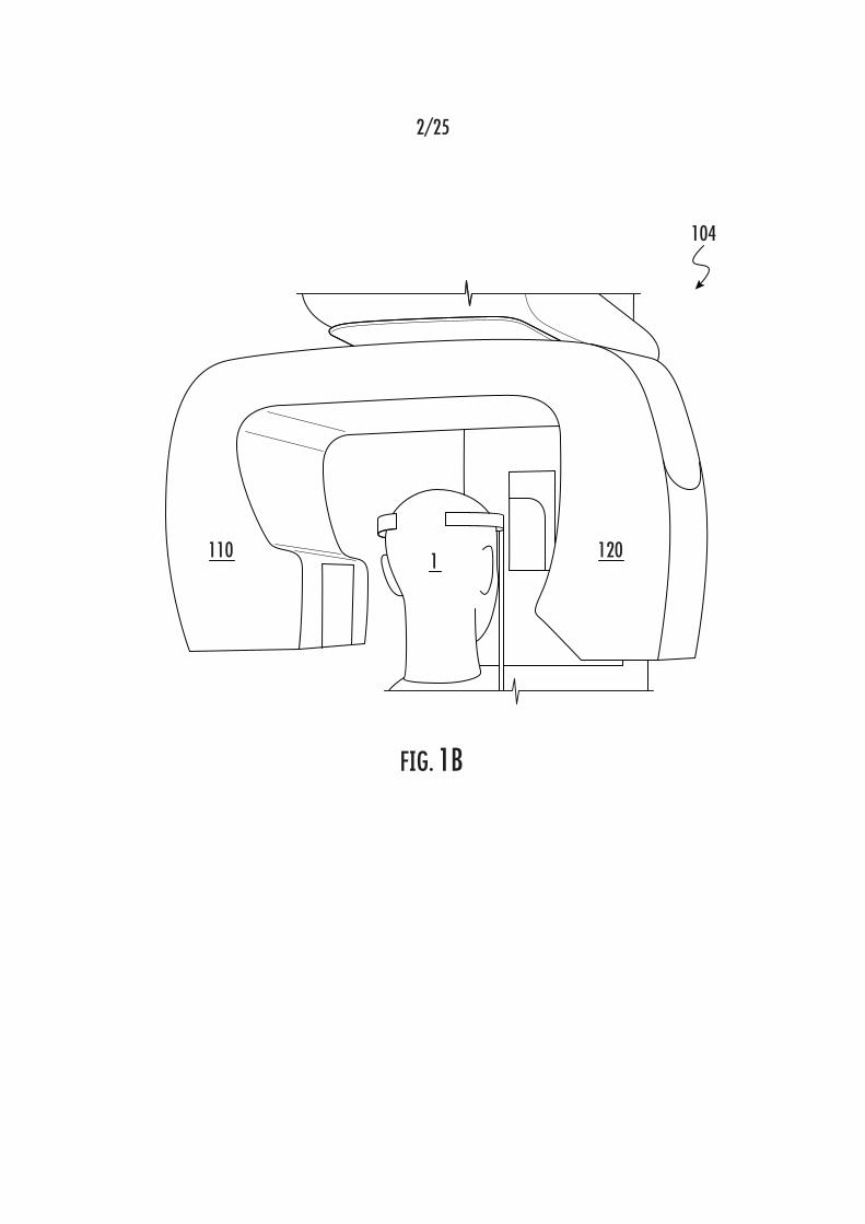
FIG. 1B shows another example embodiment of a prior art CBCT
device for use in dental imaging.
FIG. 1C schematically shows another example embodiment of a prior
art on-board CBCT imaging system incorporated in a radiation therapy device.
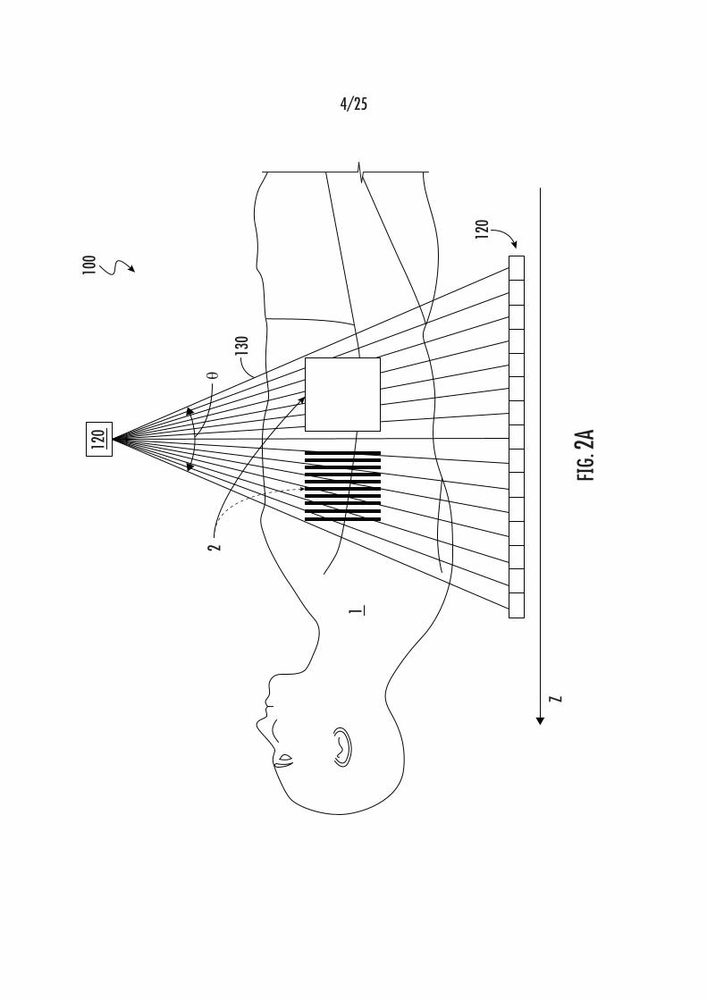
FIG. 2A schematically shows a cone beam generated using an
example embodiment of a prior art CBCT device for imaging structures,
anatomical or otherwise, that are internal to a human body.
FIG. 2B is a graphical representation of cone angle v. scatter radiation
for a prior art CBCT device.
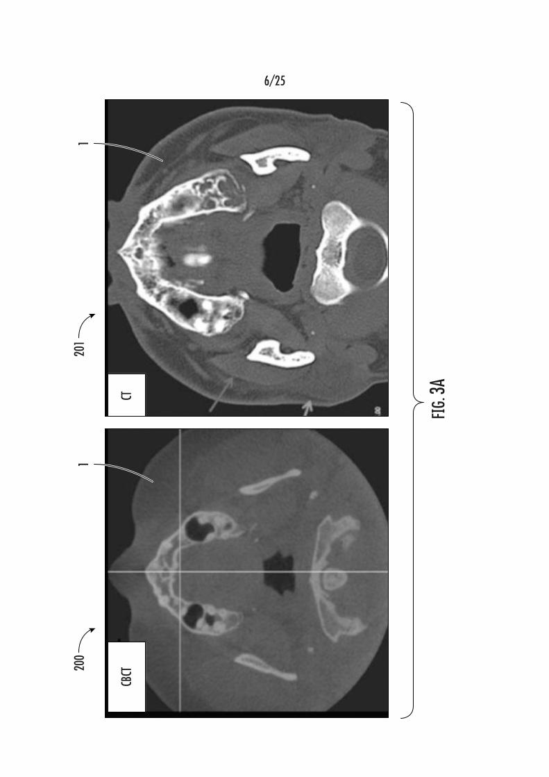
FIG. 3A is a set of images, the left image having been generated using
a prior art CBCT device and the right image having been generated using a
prior art fan-beam CT device, the set of images showing the low-contrast
resolution in CBCT imaging compared to conventional CT imaging.
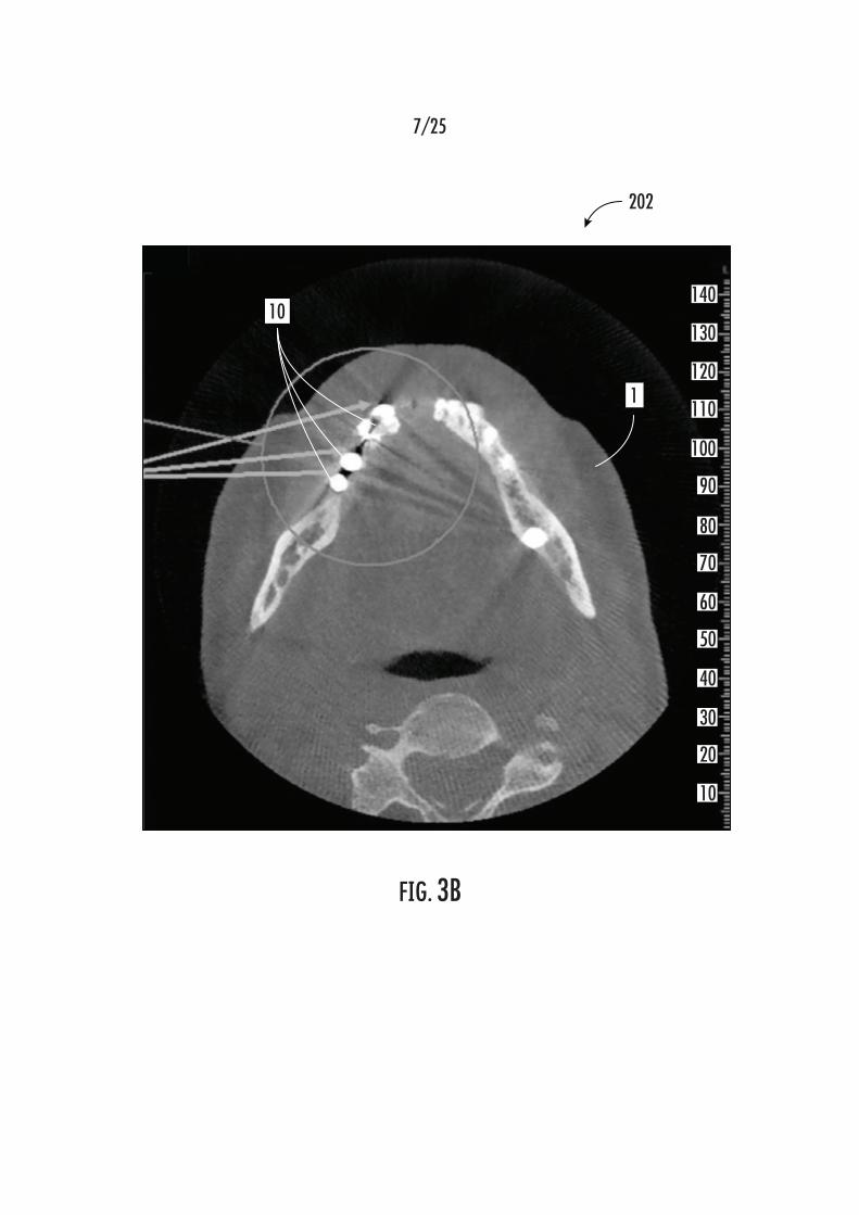
FIG. 3B is a CBCT reconstructed patient image obtained using a prior
art CBCT device, in which metal artifacts, or structures, were present in the
specimen during imaging.
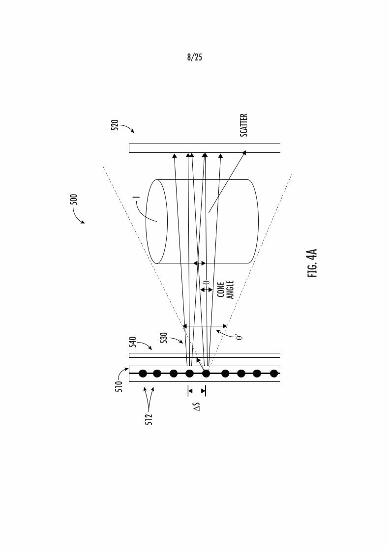
FIG. 4A schematically shows an example embodiment of a volumetric
spectral computed tomography (mSCT) imaging device or system, according
to the disclosure herein.

Attorney Docket 421/170/31 PCT
-16-
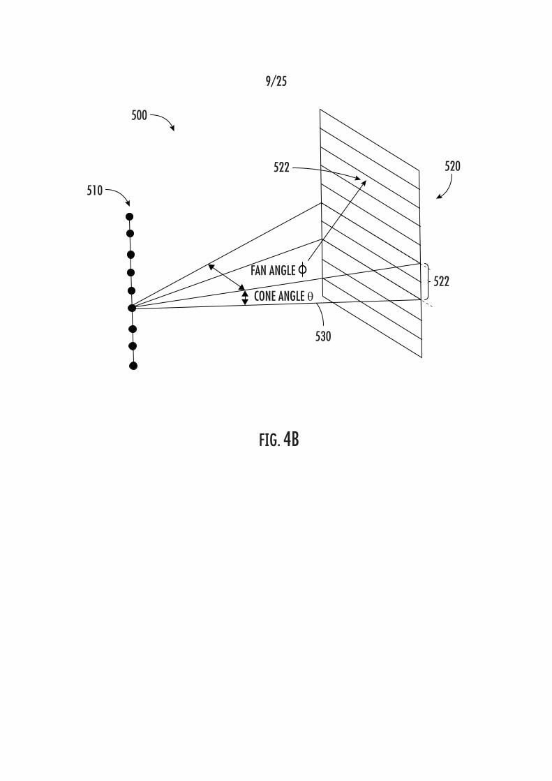
FIG. 4B schematically shows the x-ray beam from a collimated source
in the array on the flat panel detector, as is used in an mSCT imaging device,
according to the disclosure herein.
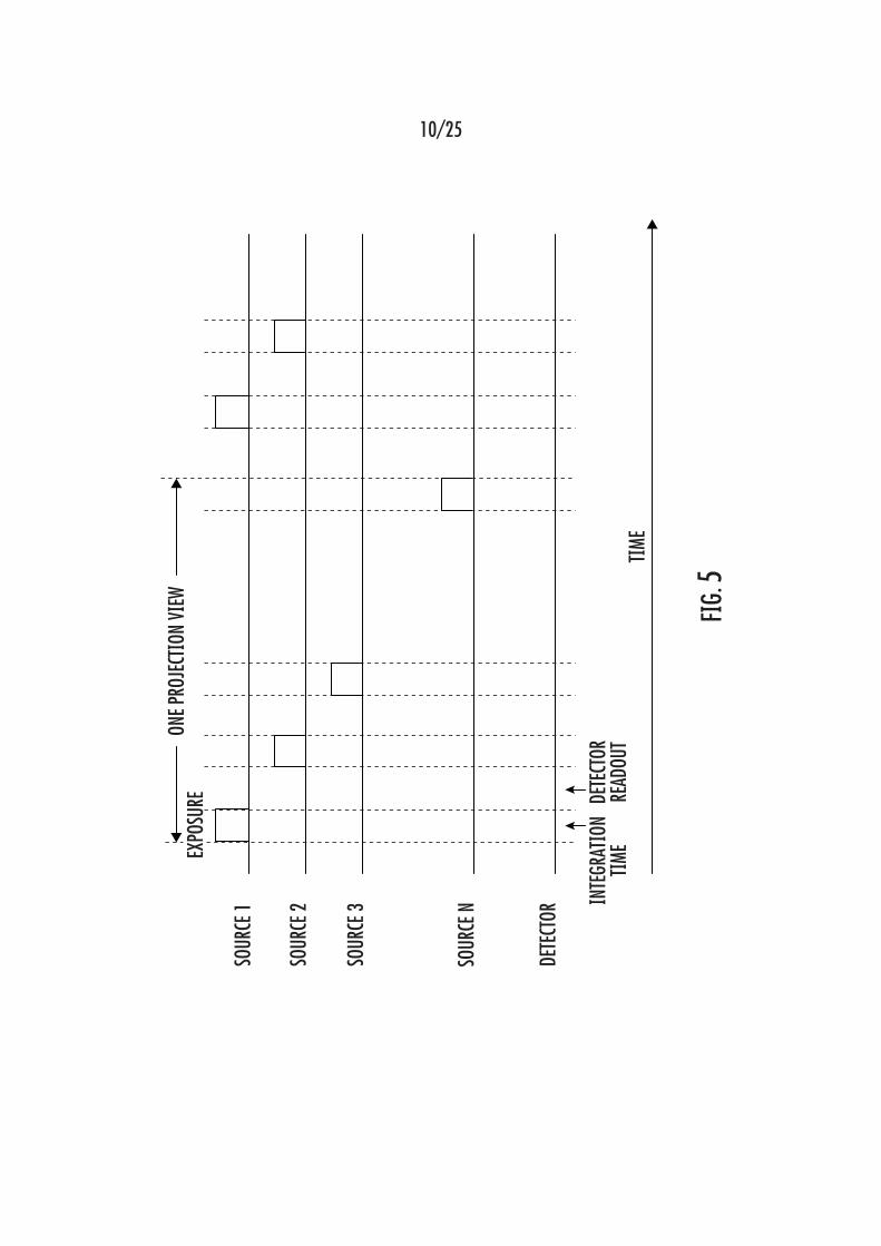
FIG. 5 is an example graphical illustration of a timing diagram showing
an example of the data acquisition process of an mSCT imaging device,
according to the disclosure herein.
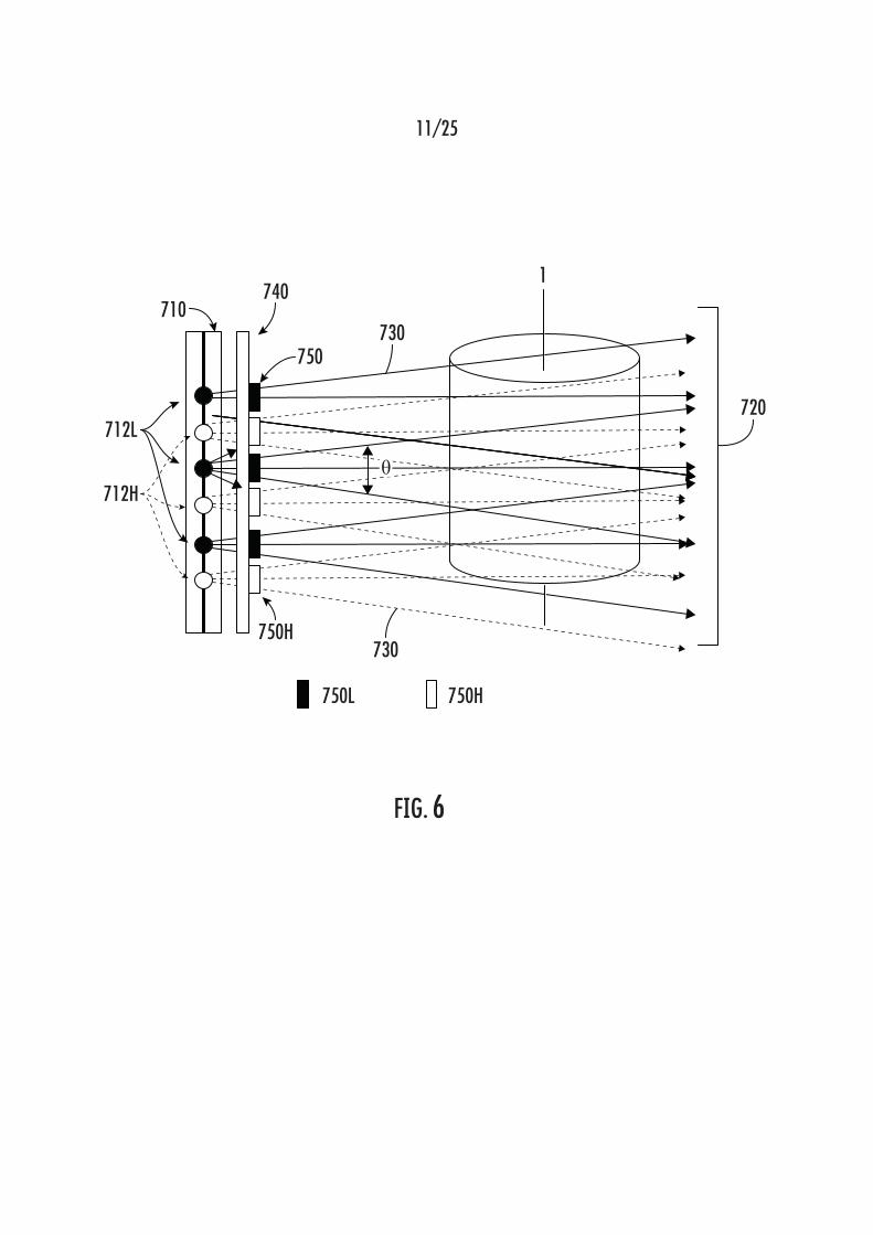
FIG. 6 schematically shows an example embodiment of a dual energy
CT (DECT) imaging of an object using mSCT, according to the disclosure
herein.
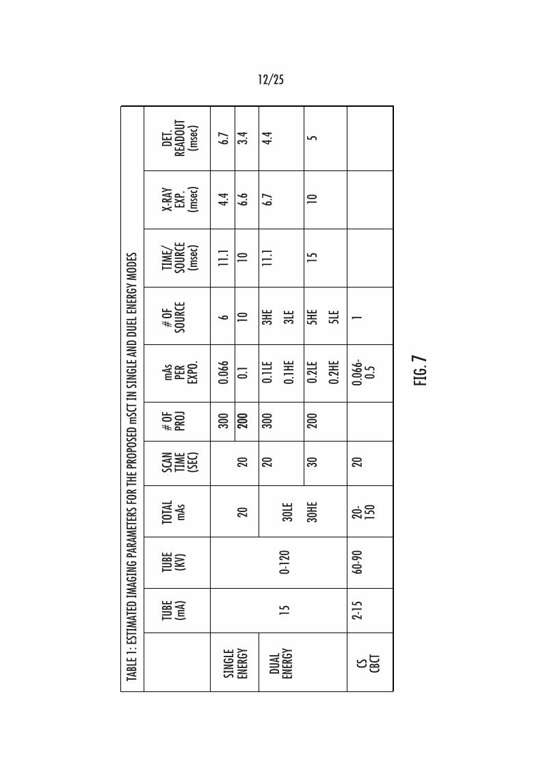
FIG. 7 is a table containing the estimated imaging parameters for an
example mSCT imaging device in single and dual energy modes and those of
a conventional CBCT, according to the disclosure herein.
FIG. 8A is a schematic illustration showing the working mechanisms of
an example embodiment of a known CNT x-ray source array.
FIG. 8B is an example embodiment of a known dental CNT x-ray
source array comprising multiple x-ray sources arranged in a linear array
inside a housing.
FIG. 8C is a graphical plot of time v. cathode current in an example
embodiment of a linear CNT x-ray source array.
FIG. 9 schematically shows an example embodiment of a dual energy
CBCT system using an x-ray source with two cathodes, two focal spots, and
two spectral filters, according to the disclosure herein.
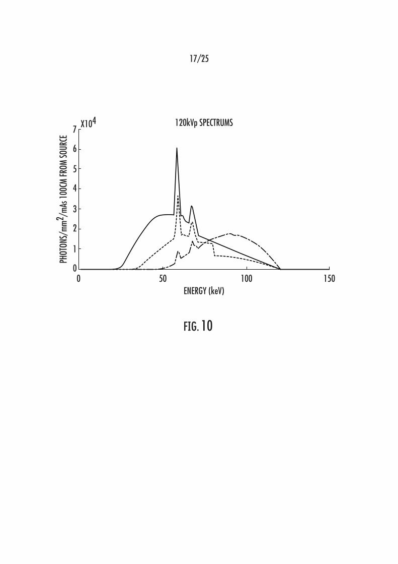
FIG. 10 is a graphical plot of simulated x-ray energy spectra from an x-
ray source of an example embodiment of a dual energy CBCT system, prior
to and after the x-rays passing through the respective LE and HE spectral
filters.
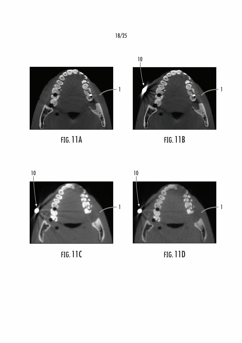
FIGS. 11A and 11B are example reconstructed CBCT images of a
human skull analogue, which images were obtained using a single energy
CBCT imaging system.
FIGS. 11C and 11D are example reconstructed CBCT images of a
human skull analogue, which images were obtained using a dual energy
CBCT imaging system.

Attorney Docket 421/170/31 PCT
-17-
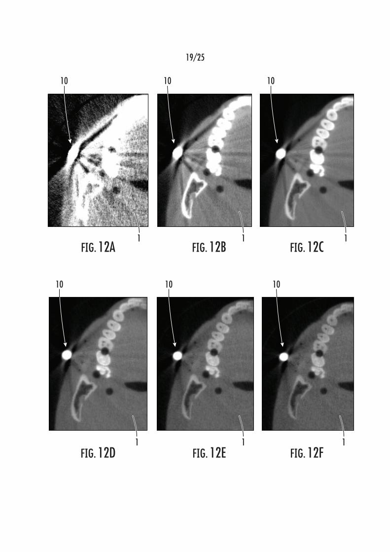
FIGS. 12A-F are enlarged portions of VMIs of a human skull analogue,
in which the images are synthesized at different energy levels.
FIGS. 13A-D schematically show various methods of implementing
DECT imaging.
FIG. 14 is an electrical schematic for an example embodiment of a dual
energy x-ray source with two cathodes and one anode.
FIG. 15 is an electrical schematic for an example embodiment of a dual
energy x-ray source with two cathode-anode pairs and a voltage divider.
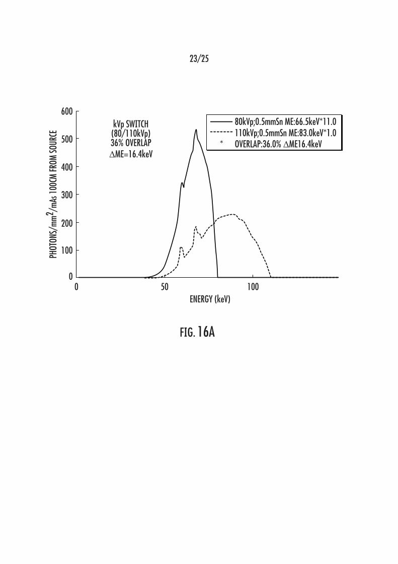
FIGS. 16A-C are graphical plots of simulated x-ray spectra for example
embodiments of dual energy CBCT systems, as disclosed herein, after the x-
rays have passed through a human skull analogue.
DETAILED DESCRIPTION
The subject matter of the present disclosure provides a multi-source
volumetric spectral CT (mSCT) imaging device. By using such an mSCT
imaging device, the known disadvantages associated with imaging using
cone-based computed tomography (CBCT), which are specifically associated
with the large cone imaging angle necessary to image an object, are remedied
by the use of an array of x-ray sources, each of which emits a cone-shaped
x-ray pattern that covers (e.g., in an overlapping manner), a portion of the
region of interest (ROI) of the object being imaged. The ROI of the object can
be less than all or all of the object, depending on the size of the object being
imaged Thus, the cone angle for each x-ray source of the mSCT imaging
device can be reduced to an angle, or value, that is approximately the same
as a diagnostic fan-beam multidetector CT (MDCT), which causes a large
reduction of the x-ray scatter and cone-beam image artifacts, at least in
comparison to a conventional CBCT imaging system. Thus, the mSCT
imaging systems disclosed herein demonstrate a significant improvement in
both CT image quality and diagnostic accuracy, compared to such
conventional CBCT imaging systems, without increasing the radiation dose
necessary to generate the requisite projection images. Such mSCT imaging
devices futher advantageously enable dual energy and/or multiple energy
imaging, as well as virtual monoenergetic imaging (VMI) without requiring the

Attorney Docket 421/170/31 PCT
-18-
use of an energy-sensitive flat panel area x-ray detector, which
advantageously reduces the imaging artifacts induced by the presence of
metallic structures in and/or around the object being imaged and, furthermore,
provides quantitatively accurate measurement of the x-ray attenuation.
Referring to FIG. 1A, an example of a prior art CBCT imaging device,
generally desigatedn 100, is shown therein. The CBCT imaging device 100
comprises an x-ray source 110 and a flat panel x-ray detector 120, which are
arranged on opposite sides of the object 1 being imaged. The x-ray source
110 generates a cone-shaped x-ray beam 112 that is directed towards and
incident upon the x-ray detector 120,. The object 1 being imaged is placed in
the center of the CBCT imaging device 100, within the x-ray beam 112, and
the x-ray source 110 and x-ray detector 120 rotate around the object 1, which
defines the axis of rotation R of the CBCT imaging device 100. Thus, the x-
ray source 110 and the x-ray detector 120 move along the rotation path 140
simultaneously, or in unison, with each other.
FIG. 1B shows an example embodiment of the prior art CBCT imaging
device of FIG. 1A, with the object 1 being positioned between the x-ray source
and the x-ray detector of the dental imaging device, generally designated 101,
such that the x-ray source and the x-ray detector will rotate about an axis of
rotation defined by the object 1, such as when used for dental imaging. FIG.
1C shows an example embodiment of the prior art CBCT imaging device 100
of FIG. 1A incorporated in a radiation therapy device, generally designated
102. In this example, the CBCT imaging device 100 is used to assist the
radiation therapy device 102 in improving the efficacy and efficiency of the
radiation therapy being performed on the object 1.
FIG. 2A schematically shows a cone-shaped x-ray beam 130, which is
generated by an x-ray source 110 of a CBCT imaging device, and
indistinguishable objects 1 contained within the body of the subject (e.g., a
human) being imaged. The cone-shaped x-ray beam has a cone angle θ and
is incident on a flat panel x-ray detector 120 arranged on an opposite side of
the objects 1 from the x-ray source 110. As shown in FIG. 2A, the geometry
of the x-ray beam 130 reduces the sensitivity of the CBCT imaging device,
since the small distances that separate the plates in the left object 1 are

Attorney Docket 421/170/31 PCT
-19-
rendered indistinguishable from the solid right object 1, due to the angle of the
x-ray beam 130. FIG. 2B is a graphical plot showing that, as the cone angle θ
increases, the scatter-to-primary ratio (%) of radiation also increases.
(Siewerdsen JH, Jaffray DA. Cone-beam computed tomography with a flat-
panel imager: Magnitude and effects of x-ray scatter. Med Phys.
2000;28(2):220, the entire contents of which are expressly incorporated herein
by reference.) Since the cone angle θ of a typical CBCT imaging device is
about 15°, it is common for conventional CBCT imaging devices to have very
high scatter-to-primary ratios for radiation.
Referring to FIG. 3A, a set of images is shown therein. The CBCT
image, generally designated 200, is generatedusing a conventional CBCT
imaging device. The fan-beam CT image, generally designated 201, is
generated using a conventional fan-beam CT imaging device. As shown in the
CBCT image 200, obtained using a conventional CBCT imaging device, the
large cone angle causes significantly higher scatter radiation compared to the
fan-beam CT image 201, obtained using a conventional fan-beam CT imaging
device. The higher scatter radiation associated with conventional CBCT
imaging devices is shown by the difference in contrast between the CBCT and
fan-beam CT images 200, 201. (Angelopoulos C, Scarfe WC, Farman AG. A
Comparison of Maxillofacial CBCT and Medical CT. Atlas Oral Maxillofacial
Surg Clin N Am. 2012;20:1-17, the entire contents of which are expressly
incorporated herein by reference.) In comparison to the fan-beam CT image
201, soft tissue structures of the object 1 being imaged are almost impossible
to identify in the CBCT image 200, but are visible in the fan-beam CT image
201.
Referring to FIG. 3B, a CBCT reconstructed image, generally
designated 202, of an object 1, which contains metallic structures 10
implanted therein, is shown. As shown in the CBCT reconstructed image 202,
the metallic structures 10 (e.g., in the form of dental implants) cause imaging
artifacts, which are generally in the form of streaks and/or dark halos around
the metallic structures 10 in the reconstructed CBCT image 202, whichreduce
the reliability of such reconstructed CBCT image(s) 202 for diagnostic
Attorney Docket 421/170/31 PCT
-20-
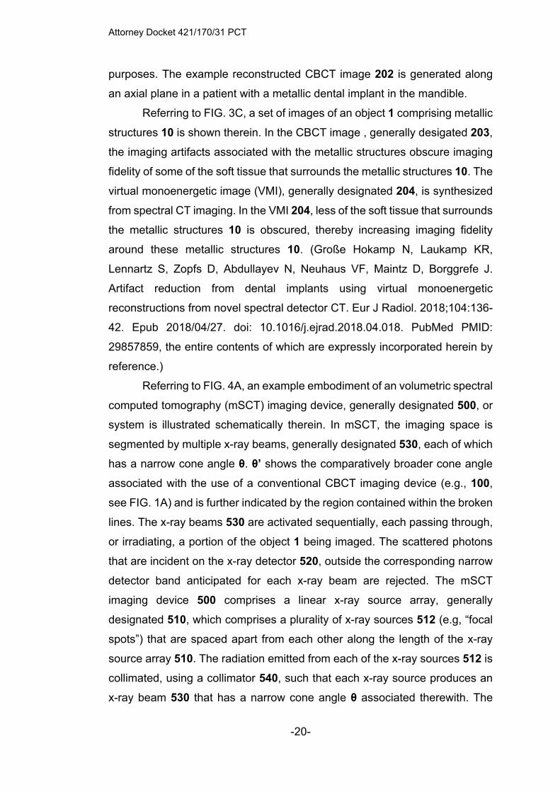
purposes. The example reconstructed CBCT image 202 is generated along
an axial plane in a patient with a metallic dental implant in the mandible.
Referring to FIG. 3C, a set of images of an object 1 comprising metallic
structures 10 is shown therein. In the CBCT image , generally desigated 203,
the imaging artifacts associated with the metallic structures obscure imaging
fidelity of some of the soft tissue that surrounds the metallic structures 10. The
virtual monoenergetic image (VMI), generally designated 204, is synthesized
from spectral CT imaging. In the VMI 204, less of the soft tissue that surrounds
the metallic structures 10 is obscured, thereby increasing imaging fidelity
around these metallic structures 10. (Große Hokamp N, Laukamp KR,
Lennartz S, Zopfs D, Abdullayev N, Neuhaus VF, Maintz D, Borggrefe J.
Artifact reduction from dental implants using virtual monoenergetic
reconstructions from novel spectral detector CT. Eur J Radiol. 2018;104:136-
42. Epub 2018/04/27. doi: 10.1016/j.ejrad.2018.04.018. PubMed PMID:
29857859, the entire contents of which are expressly incorporated herein by
reference.)
Referring to FIG. 4A, an example embodiment of an volumetric spectral
computed tomography (mSCT) imaging device, generally designated 500, or
system is illustrated schematically therein. In mSCT, the imaging space is
segmented by multiple x-ray beams, generally designated 530, each of which
has a narrow cone angle θ. θ’ shows the comparatively broader cone angle
associated with the use of a conventional CBCT imaging device (e.g., 100,
see FIG. 1A) and is further indicated by the region contained within the broken
lines. The x-ray beams 530 are activated sequentially, each passing through,
or irradiating, a portion of the object 1 being imaged. The scattered photons
that are incident on the x-ray detector 520, outside the corresponding narrow
detector band anticipated for each x-ray beam are rejected. The mSCT
imaging device 500 comprises a linear x-ray source array, generally
designated 510, which comprises a plurality of x-ray sources 512 (e.g, “focal
spots”) that are spaced apart from each other along the length of the x-ray
source array 510. The radiation emitted from each of the x-ray sources 512 is
collimated, using a collimator 540, such that each x-ray source produces an
x-ray beam 530 that has a narrow cone angle θ associated therewith. The

Attorney Docket 421/170/31 PCT
-21-
collimator 540 is positioned adjacent to the x-ray source array 510, between
the x-ray source array 510 and the object 1 being imaged. In some
embodiments, the collimator 540 is configured to cover only a portion of (i.e.,
less than an entirety of, including less than a majority of) the object 1 being
imaged.
In some embodiments, the collimator 540 is a fan-beam collimator with
an array of apertures. Each aperture is configured to confine the radiation from
a single x-ray source 512 to an x-ray beam 530 with a narrow cone angle θ.
In some such example embodiments, the collimator 540 is attached (e.g.,
directly or indirectly) to the x-ray source array 510. In some embodiments, the
mSCT imaging is performed in a simple step-and-shoot mode, in which, since
the x-ray source array 510 has, for example, a quantity of “M” x-ray sources
512, which are configured to be activated sequentially to electronically scan
(e.g., in the direction of extension of the x-ray source array 510) across the
object 1 while the x-ray source array 510 and the x-ray detector 520 is
positionally fixed at one of a quantity of “N” viewing angles defined about the
object 1 in a circumferential direction. After all “M” (or a designated portion
thereof) of the x-ray sources 510 have been activated at a single one of the
“N” viewing angle, the x-ray source array 510 and the x-ray detector 520 are
rotated, about an axis of rotation defined by the object 1, to another (e.g, an
adjacent, or next) of the “N” viewing angles and another scan (e.g., activation
of all, or a designated portion of, of the x-ray sources 512) of the object 1 is
performed, following the timing diagram illustrated in FIG. 5. This process
repeats until the x-ray source array 510 and the x-ray detector 520 have been
rotated to each of the “N” viewing angles, which is typically either 180° plus
the cone angle θ (i.e., 180° + the cone angle θ) or 360 degrees. For each x-
ray exposure (e.g., activation and/or energizing of one of the x-ray sources
512), an image of a portion of the object 1 being imaged is recorded on a
portion of the x-ray detector 520, referred to as a “detector band” that
corresponds to only a single, or multiples of, the x-ray sources 512. Any
scattered photon from an x-ray source 512 that is received by the x-ray
detector outside of the “detector band” that corresponds to the x-ray source
512 that was activated, or energized, is rejected. During mSCT imaging
Attorney Docket 421/170/31 PCT
-22-
according to the steps of the example process disclosed herein, a total of the
product of the “M” x-ray sources 512 multiplied by the “N” viewing angles
defines the number of projection images of the object that are collected.
In some embodiments, the x-ray detector 520 is a digital area x-ray
detector that uses a dynamic band reading method, or region-of-interest (ROI)
readout, to increase a data readout speed of the digital area x-ray detector.
After exposure of the digital area x-ray detector from each collimated x-ray
beam, only a “band,” or ROI, of the x-ray detector that receives primary
transimitted x-ray photons is read by the digital area x-ray detector instead of
the entire detector which the amount of the data read and transmitted.
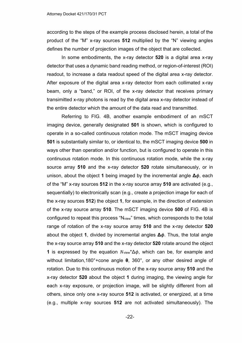
Referring to FIG. 4B, another example embodiment of an mSCT
imaging device, generally designated 501 is shown, which is configured to
operate in a so-called continuous rotation mode. The mSCT imaging device
501 is substantially similar to, or identical to, the mSCT imaging device 500 in
ways other than operation and/or function, but is configured to operate in this
continuous rotation mode. In this continuous rotation mode, while the x-ray
source array 510 and the x-ray detector 520 rotate simultaneously, or in
unison, about the object 1 being imaged by the incremental angle Δ𝜙, each
of the “M” x-ray sources 512 in the x-ray source array 510 are activated (e.g.,
sequentially) to electronically scan (e.g., create a projection image for each of
the x-ray sources 512) the object 1, for example, in the direction of extension
of the x-ray source array 510. The mSCT imaging device 500 of FIG. 4B is
configured to repeat this process “Nview” times, which corresponds to the total
range of rotation of the x-ray source array 510 and the x-ray detector 520
about the object 1, divided by incremental angles Δ𝜙. Thus, the total angle
the x-ray source array 510 and the x-ray detector 520 rotate around the object
1 is expressed by the equation 𝑁view*Δ𝜙, which can be, for example and
without limitation,180°+cone angle θ, 360°, or any other desired angle of
rotation. Due to this continuous motion of the x-ray source array 510 and the
x-ray detector 520 about the object 1 during imaging, the viewing angle for
each x-ray exposure, or projection image, will be slightly different from all
others, since only one x-ray source 512 is activated, or energized, at a time
(e.g., multiple x-ray sources 512 are not activated simultaneously). The

Attorney Docket 421/170/31 PCT
-23-
different viewing angles for each x-ray exposure is accounted for during image
reconstruction. During mSCT imaging according to the steps of the example
process disclosed herein, a total of the product of the “M” x-ray sources 512
multiplied by the “Nview” viewing angles defines the number of projection
images of the object that are collected.
The mSCT imaging devices 500, 501 are essentially fan-beam CT
imaging devices, each having an x-ray source array 510 and an x-ray detector
520 that extend, respectively, in the axial direction to cover a large field-of-
view without requiring movement of the object being imaged (e.g., without
patient translation). Using the geometry of a typical dental CBCT, it is
estimated that the cone angle can be decreased from about 15° in a
conventional CBCT imaging device to about 3° in the example mSCT imaging
devices 500, 501 disclosed herein. Such a reduction in cone angle reduces
the scatter-to-primary ratio by a factor of about 5.
In another example embodiment, the mSCT imaging device is
configured to be used to perform dual-energy CT (DECT) imaging. Spectral
CT or virtual monoenergetic imaging (VMI) synthesized from DECT data
reduces imaging artifacts caused by materials with high atomic numbers, such
as is common in metallic structures implanted within a human body.
According to another example embodiment, an mSCT imaging device,
generally designated 700, is shown in FIG. 6. This mSCT imaging device 700
is configured to allow DECT imaging at low cost, without the need to use an
energy-sensitive area x-ray detector. As shown in FIG. 6, the mSCT imaging
device 700 is substantially similar to the mSCT imaging devices 500, 501, but
the x-ray source array 710 is divided into a first set of x-ray sources, generally
designated 712L, and a second set of x-ray sources, generally designated
712H.
The mSCT imaging device 700 comprises a plurality of first filters 750L,
each of which is positioned adjacent to one of the first group of x-ray sources
712L (e.g., between an x-ray source 712L and the object 1 being imaged),
such that x-ray radiation emitted from every one of the first group of x-ray
sources 750L is filtered by one of the first filters 750L, which comprise a first
material that preferentially attenuates high-energy photons to produce a low

Attorney Docket 421/170/31 PCT
-24-
mean energy (LE) x-ray spectrum. In some embodiments, the quantity of first
filters 750L is the same as the quantity of the x-ray sources 712L in the first
group of the x-ray sources 712L. The mSCT imaging device 700 also
comprises a plurality of second filters 750H, each of which is positioned
adjacent to one of the second group of x-ray sources 712H (e.g., between an
x-ray source 712H and the object 1 being imaged), such that x-ray radiation
emitted from every one of the second group of x-ray sources 712H is filtered
by one of the second filters 750H, which comprise a second material that
preferentially attenuates low energy photons to produce a high mean energy
(HE) x-ray spectrum.
Thus, each x-ray source 712L can be referred to herein
interchangeably as “LE x-ray source 712L,” each x-ray source 712H can be
referred to herein interchangeably as “HE x-ray source 712H,” each first filter
750L can be referred to herein interchangeably as “LE filter 750L,” and each
second filter 750H can be referred to herein interchangeably as “HE filter
750H.” However, the LE x-ray sources 712L are substantially identical to, and
emit an x-ray beam that is substantially similar in terms of x-ray energy spectra
to, the HE x-ray sources 712H. The differentiation of x-ray spectra energy is
produced based on whether the x-ray beam passes through an LE filter 750L
or an HE filter 750H. In the example embodiment shown, the LE x-ray sources
712L are positioned, along the length of the x-ray source array 710, between
the HE x-ray sources 712H in an alternating pattern, in which, other than a
first and a last x-ray source of the x-ray source array 710, each LE x-ray
source 712L is adjacent to, or positioned between, HE x-ray sources 712H
and each HE x-ray source 712H is adjacent to, or positioned between, LE x-
ray sources 712L. As such, the LE and HE x-ray sources 712L, 712H are
arranged, respectively, as pairs that are adjacent to each other along the
length of the x-ray source array 710, each pair comprising one LE x-ray source
712L and one HE x-ray source 712H.
The aggregation of the projection images from each set of the x-ray
sources 712L and 712H is sufficient to reconstruct the CT image of the object
1 at the corresponding energy spectrum. Thus, during a single rotation (e.g.,
about 360°) of the x-ray source array 710 and the x-ray detector 720 around

Attorney Docket 421/170/31 PCT
-25-
the object 1, two complete sets of CT images are generated, a first set of CT
images being generated at low energy from the x-ray sources 712L and a
second set of CT images being generated at high energy from the x-ray
sources 712H. The mSCT imaging device 700 is operable without using an
energy-sensitive area x-ray detector, which are known to be prohibitively
expensive (e.g., to the point of rendering the . In a further example
embodiment, CT imaging at more than two energy levels can also be
performed by using multiple (e.g., more than two) energy filters.
In some embodiments of the mSCT imaging device 700, the HE filter
750H comprises, for example and without limitation, a thin foil of copper, which
preferentially attenuates more (e.g., a greater proportion of) low energy
photons and thereby is operable to increase the mean energy of the resulting
photon spectrum emitted from the HE filter 750H towards the object 1 being
imaged. In some embodiments of the mSCT imaging device 700, the LE filter
750L comprises, for example and without limitation, a thin foil of tantalum or
tin, which preferentially attenuates more (e.g., a greater proportion of) high
energy photons and thereby is operable to reduce the mean energy of the
resulting photon spectrum emitted from the LE filter 750L towards the object
1 being imaged. Each set of projection images will be reconstructed
separately into high and low energy CT images. Stated somewhat differently,
all of the projection images generated while any of the LE x-ray sources 712L
is activated are reconstructed to produce low energy CT image(s) and all of
the projection images generated while any of the HE x-ray sources 712H is
activated are reconstructed to produce high energy CT image(s).
By decomposing each image voxel into two base materials their density
at each voxel can be obtained. With pre-calibrated energy dependence of
mass attenuation of each material, virtual monochromatic energy images of
the object can be obtained at any suitable energy level. In some embodiments,
the dual energy datasets (e.g., image projections and/or CT images)
generated using the mSCT imaging device 700 are suitable for use in
synthesizing virtual monoenergetic CT images. By measuring the attenuations
at two different energies, the effective atomic number and the density of the
two basis materials (for example, water and iodine) in a voxel can be
Attorney Docket 421/170/31 PCT
-26-
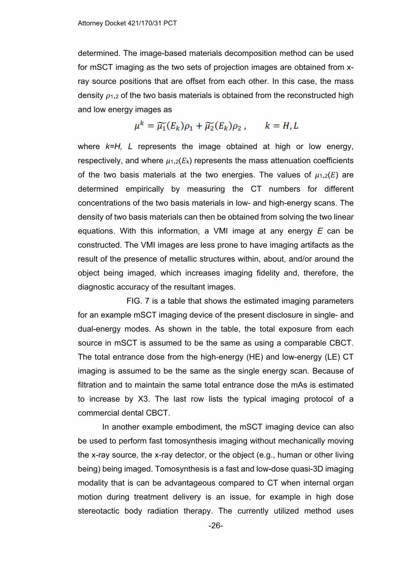
determined. The image-based materials decomposition method can be used
for mSCT imaging as the two sets of projection images are obtained from x-
ray source positions that are offset from each other. In this case, the mass
density 𝜌1,2 of the two basis materials is obtained from the reconstructed high
and low energy images as
where k=H, L represents the image obtained at high or low energy,
respectively, and where 𝜇1,2(𝐸k) represents the mass attenuation coefficients
of the two basis materials at the two energies. The values of 𝜇1,2(𝐸) are
determined empirically by measuring the CT numbers for different
concentrations of the two basis materials in low- and high-energy scans. The
density of two basis materials can then be obtained from solving the two linear
equations. With this information, a VMI image at any energy E can be
constructed. The VMI images are less prone to have imaging artifacts as the
result of the presence of metallic structures within, about, and/or around the
object being imaged, which increases imaging fidelity and, therefore, the
diagnostic accuracy of the resultant images.
FIG. 7 is a table that shows the estimated imaging parameters
for an example mSCT imaging device of the present disclosure in single- and
dual-energy modes. As shown in the table, the total exposure from each
source in mSCT is assumed to be the same as using a comparable CBCT.
The total entrance dose from the high-energy (HE) and low-energy (LE) CT
imaging is assumed to be the same as the single energy scan. Because of
filtration and to maintain the same total entrance dose the mAs is estimated
to increase by X3. The last row lists the typical imaging protocol of a
commercial dental CBCT.
In another example embodiment, the mSCT imaging device can also
be used to perform fast tomosynthesis imaging without mechanically moving
the x-ray source, the x-ray detector, or the object (e.g., human or other living
being) being imaged. Tomosynthesis is a fast and low-dose quasi-3D imaging
modality that is can be advantageous compared to CT when internal organ
motion during treatment delivery is an issue, for example in high dose
stereotactic body radiation therapy. The currently utilized method uses

Attorney Docket 421/170/31 PCT
-27-
multiple CBCT scans to monitor the motion of the internal organs, which
significantly increases both the time needed to perform the imaging and also
the radiation dose to which the patient is exposed during such imaging.
In another embodiment of the present disclosure, the mSCT device can
also be used to perform fast tomosynthesis imaging without mechanically
moving the source, detector, or subject being imaged. Tomosynthesis is a fast
and low-dose quasi-3D imaging modality. It is potentially advantageous
compared to CT when internal organ motion during treatment delivery is an
issue, for example in high dose stereotactic body radiation therapy. The
current approach of using multiple CBCT scans to monitor the motion
significantly increases the time and dose to the patient. Using the multiple x-
ray sources and the flat-panel detector in mSCT tomosynthesis imaging of the
patient can be performed without gantry movement in a few seconds
(compared to 60-120sec for one CBCT scan). The fan-beam collimator is
replaced by a multiple beam cone beam collimator. The radiation from each
source is collimated to cover the entire FOV to form a projection image of the
object from a particular viewing angle. By electronically activating multiple x-
ray sources in the array sequentially, a set of projection images are collected
without movement of the source, detector or object. The images are then
reconstructed into a stack of tomosynthesis slices by a tomosynthesis
reconstruction algorithm.
In another example embodiment, an mSCT imaging device can be
used to perform physiologically gated tomosynthesis imaging using the same
source array and the same flat panel detector, without requiring any
mechanical movement thereof. In an example, the mSCT imaging device is
used for respiratory gated tomosynthesis imaging of the lung(s) of a subject,
or patient, for example, a human subject for image-guided radiation therapy.
According to this example embodiment, a respiratory signal from the subject
being imaged is used to trigger activation of the x-ray sources and the x-ray
detectors and, necessarily, to activatedata collection from such x-ray sources
and/or x-ray detectors. According to this example embodiment, during which
phase of the respiratory cycle that the series of x-ray projection images are
generated can be selected based on individual diagnostic considerations. In

Attorney Docket 421/170/31 PCT
-28-
some embodiments, the selection of the phase of the respiratory cycle can be
selected from a graphical user interface (GUI), for example, on a touchscreen
device. Since each projection image is generated during a particular phase
and time window during a respiratory cycle, image blur of the resultant
projection images due to motion of the lung is minimized. In some
embodiments, the triggering signal is used to control the electron emission
from one or more of the x-ray sources. In such embodiments, electron
emission is activated when a signal is received to activate a corresponding
one of the x-ray sources and the electron emission is deactivated at the end
of the x-ray exposure, such as upon receipt of a deactivation signal or after a
prescribed period of time has elapsed.
In another example embodiment, such mSCT imaging devices can be
used for tomosynthesis imaging of an object from a projected view that is
spanned by a two-dimensional (2D) area. In such an example embodiment,
the x-ray radiation from each x-ray source in the x-ray source array is
collimated to illuminate the entirety of the object, such that, as the “M” x-ray
sources are sequentially activated, the projection view of the object is spanned
by Δ𝜃, as defined by the cone beam direction. As the x-ray source array and
the x-ray detector rotate simultaneously, or in unison, around the object being
imaged by angle Δ𝜙 in “Nview” steps, as defined by the fan beam direction, the
total solid viewing angle spanned is Δ𝜙 x Δ𝜃. The collection of the quantity of
“Nview” x “M” projection images are used for tomosynthesis reconstruction of
the object from a distribution of sources in a 2D area x-ray source array (e.g.,
spanning in both x and y directions, as defined using typical cartesian
coordinates, with the z direction generally being defined as the direction
between the array and the object and/or the x-ray detector). Tomosynthesis
images that are produced using such a 2D area x-ray source array is of
superior quality to that of tomosynthesis images that are produced using a 1D,
or linear, x-ray source array in either the cone beam direction or the fan beam
direction.
In another example embodiment, the mSCT imaging device comprises
multiple individual x-ray tubes that are linearly positioned (e..g., along a line)
along the axial direction of the object.

Attorney Docket 421/170/31 PCT
-29-
In another example embodiment, the mSCT imaging device comprises
a scanning electron beam x-ray source. In such an embodiment, the electron
beam generated by an electron cathode is “steered” (e.g., pointed, in a
controllable manner) by an electromagnetic field to different points on the x-
ray anode, so that the x-ray radiation is emitted from different origin positions
on the x-ray anode based on the position on the x-ray anode on which the
electron beam is incident. In another example embodiment, a spatially
distributed x-ray source array is used. The x-ray source array can use either
an array of thermionic cathodes or an array of field emission cathodes.
In another example embodiment, the mSCT imaging device comprises
a spatially distributed x-ray source array, which uses carbon nanotube (CNT)
field emission cathodes. The plurality of cathodes are distributed linearly (e.g.,
along a line) on either one or a plurality of x-ray anodes. The entire x-ray
source array is contained inside an evacuated (e.g., negatively pressurized,
such as in a vacuum) metal housing. A high voltage difference is established
between the cathode(s) and the anode(s). X-ray radiation from a specific focal
spot is emitted by applying a bias electric field between the corresponding
cathode and gate electrode. By switching on and off the bias field applied to
the individual electron source, a scanning x-ray beam is generated.
CNT x-ray source arrays with different configurations and
specifications have been determined to be advantageous for use in mSCT for
at least the following reasons: (1) x-ray generation can be rapidly switched
and synchronized with data acquisition; (2) x-ray source arrays with small
inter-source spacing can be fabricated; (3) the x-ray source array is compact
and relatively light weight, thereby allowing retrofitting of current CBCT
scanners with such x-ray source arrays for mSCT imaging. At the same focal
spot size, each x-ray source of the CNT x-ray source array can generate the
same x-ray photon flux as a conventional x-ray tube. This has been
determined to be sufficient for the example mSCT imaging devices disclosed
herein, as illustrated in FIG. 7. For the mSCT imaging device, it is possible to
use an x-ray source with the specification comparable to that which is used in
current dental CBCT systems, which provides sufficient x-ray photon flux for
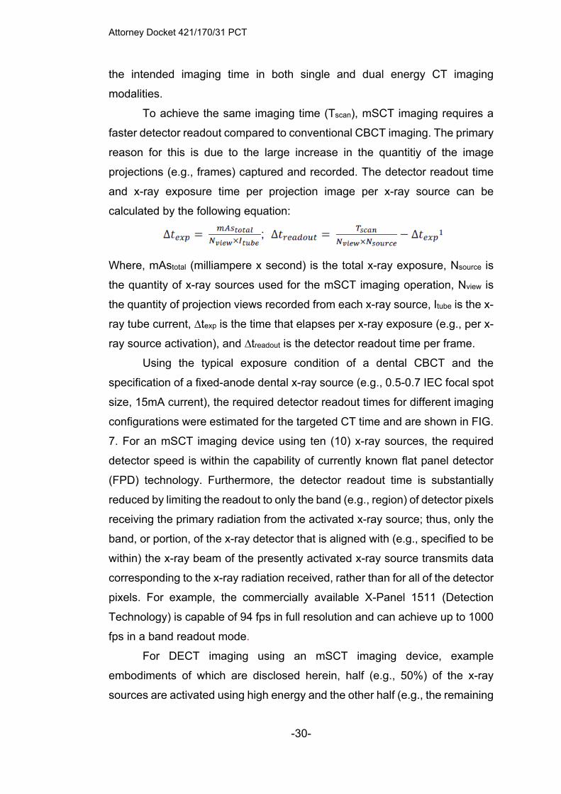
Attorney Docket 421/170/31 PCT
-30-
the intended imaging time in both single and dual energy CT imaging
modalities.
To achieve the same imaging time (Tscan), mSCT imaging requires a
faster detector readout compared to conventional CBCT imaging. The primary
reason for this is due to the large increase in the quantitiy of the image
projections (e.g., frames) captured and recorded. The detector readout time
and x-ray exposure time per projection image per x-ray source can be
calculated by the following equation:
Where, mAstotal (milliampere x second) is the total x-ray exposure, Nsource is
the quantity of x-ray sources used for the mSCT imaging operation, Nview is
the quantity of projection views recorded from each x-ray source, Itube is the x-
ray tube current, ∆texp is the time that elapses per x-ray exposure (e.g., per x-
ray source activation), and ∆treadout is the detector readout time per frame.
Using the typical exposure condition of a dental CBCT and the
specification of a fixed-anode dental x-ray source (e.g., 0.5-0.7 IEC focal spot
size, 15mA current), the required detector readout times for different imaging
configurations were estimated for the targeted CT time and are shown in FIG.
7. For an mSCT imaging device using ten (10) x-ray sources, the required
detector speed is within the capability of currently known flat panel detector
(FPD) technology. Furthermore, the detector readout time is substantially
reduced by limiting the readout to only the band (e.g., region) of detector pixels
receiving the primary radiation from the activated x-ray source; thus, only the
band, or portion, of the x-ray detector that is aligned with (e.g., specified to be
within) the x-ray beam of the presently activated x-ray source transmits data
corresponding to the x-ray radiation received, rather than for all of the detector
pixels. For example, the commercially available X-Panel 1511 (Detection
Technology) is capable of 94 fps in full resolution and can achieve up to 1000
fps in a band readout mode.
For DECT imaging using an mSCT imaging device, example
embodiments of which are disclosed herein, half (e.g., 50%) of the x-ray
sources are activated using high energy and the other half (e.g., the remaining
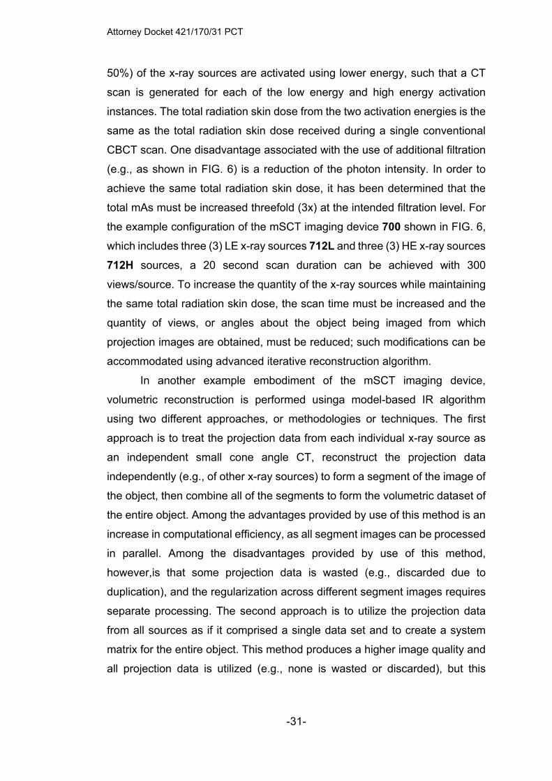
Attorney Docket 421/170/31 PCT
-31-
50%) of the x-ray sources are activated using lower energy, such that a CT
scan is generated for each of the low energy and high energy activation
instances. The total radiation skin dose from the two activation energies is the
same as the total radiation skin dose received during a single conventional
CBCT scan. One disadvantage associated with the use of additional filtration
(e.g., as shown in FIG. 6) is a reduction of the photon intensity. In order to
achieve the same total radiation skin dose, it has been determined that the
total mAs must be increased threefold (3x) at the intended filtration level. For
the example configuration of the mSCT imaging device 700 shown in FIG. 6,
which includes three (3) LE x-ray sources 712L and three (3) HE x-ray sources
712H sources, a 20 second scan duration can be achieved with 300
views/source. To increase the quantity of the x-ray sources while maintaining
the same total radiation skin dose, the scan time must be increased and the
quantity of views, or angles about the object being imaged from which
projection images are obtained, must be reduced; such modifications can be
accommodated using advanced iterative reconstruction algorithm.
In another example embodiment of the mSCT imaging device,
volumetric reconstruction is performed usinga model-based IR algorithm
using two different approaches, or methodologies or techniques. The first
approach is to treat the projection data from each individual x-ray source as
an independent small cone angle CT, reconstruct the projection data
independently (e.g., of other x-ray sources) to form a segment of the image of
the object, then combine all of the segments to form the volumetric dataset of
the entire object. Among the advantages provided by use of this method is an
increase in computational efficiency, as all segment images can be processed
in parallel. Among the disadvantages provided by use of this method,
however,is that some projection data is wasted (e.g., discarded due to
duplication), and the regularization across different segment images requires
separate processing. The second approach is to utilize the projection data
from all sources as if it comprised a single data set and to create a system
matrix for the entire object. This method produces a higher image quality and
all projection data is utilized (e.g., none is wasted or discarded), but this

Attorney Docket 421/170/31 PCT
-32-
method also typically requires large memory allocation and/or utilization and
heavy computational requirements.
The mSCT imaging devices/systems disclosed herein can overcome
many of the limitations inherent in conventional CBCT imaging. For example,
such mSCT imaging devices/systems reduce the scatter radiation and cone-
beam imaging artifacts associated with conventional CBCT imaging by
decreasing the cone beam angle to about that of a medical fan-beam CT
imaging device, but without sacrificing volumetric imaging capability. This
approach has been demonstrated to reduce imaging noise (e.g., background
signal or that from an interfering source) and increase the contrast-to-noise
ratio (CNR) and also to improve soft tissue visualization, enabling mSCT to
be used for diagnosis of soft tissue pathology. Such mSCT imaging
devices/systems also minimize imaging artifacts induced by the presence of
metallic structures on, in, or around the object being imaged by enabling dual
energy CT (DECT) and performing virtual monochromatic imaging (VMI) at
low cost. VMI reduces metal-induced imaging artifacts, which improves
diagnostic accuracy of the resultant images, especially in areas surrounding,
for example, dental restorations with high atomic mass (Z) materials, such as
fillings and implants. Further, 3D imaging is enabled for not only preoperative
implant planning but also postoperative evaluation of the quality and
osseointegration of implants, an important clinical task that is currently
performed by 2D x-ray due to the presence of metal-induced imaging artifacts
inherent in using conventional CBCT imaging techniques. The mSCT imaging
devices/systems also allow for accurate measurement of the x-ray attenuation
coefficient for various materials and enables basis materials decomposition.
Accurate measurement of bone mineral density (BMD) provides more reliable
assessment of the quality of craniofacial bone structures and can provide an
enhanced indication of dental implant stability and survival rate, which results
in more accurate clinical decisions, including tasks such as installation of
dental implants and, in some instances, evaluation for osteoporosis.
FIG. 8A illustrates the working mechanisms of a CNT x-ray source
array, generally designated 1000, which comprises an anode 1010, a cathode
assembldy 1030 comprises a plurality of cathodes 1032. Each of the cathodes

Attorney Docket 421/170/31 PCT
-33-
is in electrical communication with a control circuit 1050, sometimes referred
to as a controller. Each control circuit 1050 controls activation of the
corresponding cathode 1032 to which the control circuit 1050 is attached.
When activated, the cathode 1032 emits an electron beam 1035 towards and
incident upon the anode 1010. FIG. 8B illustrates an example dental CNT x-
ray source array, generally designated 1100, comprising or consisting of
multiple x-ray sources arranged in a linear x-ray source array inside the
evaluated housing that weighs less than 2.5kg. The x-ray source can be, for
example, a CNT x-ray source such as is manufactured commercially by
NuRay Technology.
FIG. 8C is a graphical plot of cathode current v. time for a linear CNT
x-ray source array with 45 focal spots operating at 120kVp and 15mA per focal
spot. The output power and consistency meet the requirement for mSCT
imaging.
Referring to FIGS. 9-16C, various aspects of a dual energy cone-basec
computed tomography (DE-CBCT) imaging device are disclosed, the DE-
CBCT imaging devices using a single carbon nanotube (CNT) x-ray source
with dual focal spots and by synthesizing virtual monoenergetic images (VMIs)
to reduce the appearance and impact of metal-induced imaging artifacts.
A clinically-used conventional CBCT imaging system is suitable for
dental imaging and comprises an x-ray source and an x-ray detector, which
are positioned on substantially opposite sides of an object, such as a human
skull, such that the x-ray source generates an x-ray beam that passes through
the object and is incident on the x-ray detector. The x-ray detector can be a
flat=panel x-ray detector.
A dual-energy CBCT (DE-CBCT) imaging system, or a multiple-energy
CBCT (ME-CBCT) imaging system, is disclosed herein. Such DE-CBCT
imaging systems have an x-ray source containing two or more independently
controllable and operable x-ray focal spots (e.g., on one or more anodes) and
an x-ray detector. According to an example embodiment of such a system, the
x-ray source and the x-ray detector are mounted on a rotating gantry, or other
suitable rotatable support structure, that rotates around the object being
imaged to collect the projection images for CT reconstruction. Radiation from

Attorney Docket 421/170/31 PCT
-34-
the multiple x-ray focal spots on the anode in the x-ray source are individually
filtered by one of a plurality of different spectral filters to optimize the energy
separation between the x-ray radiation generated from different focal spots
and to minimize the spectral overlap therebetween. It is further advantageous,
in some example embodiments, to apply voltage dividers, such as power
resistors, to the x-ray source to change the effective voltages (e.g., to apply a
voltage bias, or offset) between the cathode and the anode, such that the
radiation produced from one or more (e.g., each) focal spot has a different
energy spectrum for the same applied x-ray tube voltage, before spectral
filtration of such radiation by the spectral filters..
FIG. 9 schematically illustrates an example embodiment of a DE-CBCT
imaging system, generally designated 1200. The DE-CBCT imaging system
1200 comprises a CNT x-ray source, generally designated 1210, which has
two focal spots, and a flat-panel x-ray detector 1220. In determining feasibility
for operating this DE-CBCT system 1200, the x-ray source 1210 and the x-ray
detector 1220 were held stationary and the object 1 (e.g., a human skull
analogue) was rotated. In order to have a baseline for comparison, the
conventional CBCT imaging system (Carestream CS9300) was also used to
produce CT images of the same object 1. The human skull analogue used
was a Rando adult skull and tissue-equivalent head phantom, with 0.25” and
0.125” diameter stainless steel metal beads embedded therein.
Thus, the example embodiment of the DE-CBCT system 1200
comprises a CNT x-ray source 1210, an x-ray detector 1220, and a rotatable
support structure for the object 1. During imaging of the object 1, two distinct
x-ray spectra with low and high mean energies were generated by applying
spectral filters at the constant x-ray tube voltage. The spectral filters comprise
a low-energy (LE) filter 1250L, which comprises a material that preferentially
attenuates high-energy photons to produce a low mean energy (LE) x-ray
spectrum, and a high-energy (HE) filter 1250H, which comprises a material
that preferentially attenuates low-energy photons to produce a high mean
energy (HE) x-ray spectrum. X-ray energy spectrum were simulated to select
the appropriate material(s) for use in the respective spectral filters and to
investigate the effect of spectral filtration on the x-ray tube output power
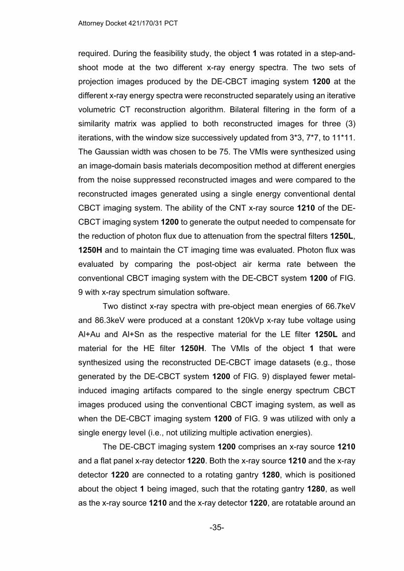
Attorney Docket 421/170/31 PCT
-35-
required. During the feasibility study, the object 1 was rotated in a step-and-
shoot mode at the two different x-ray energy spectra. The two sets of
projection images produced by the DE-CBCT imaging system 1200 at the
different x-ray energy spectra were reconstructed separately using an iterative
volumetric CT reconstruction algorithm. Bilateral filtering in the form of a
similarity matrix was applied to both reconstructed images for three (3)
iterations, with the window size successively updated from 3*3, 7*7, to 11*11.
The Gaussian width was chosen to be 75. The VMIs were synthesized using
an image-domain basis materials decomposition method at different energies
from the noise suppressed reconstructed images and were compared to the
reconstructed images generated using a single energy conventional dental
CBCT imaging system. The ability of the CNT x-ray source 1210 of the DE-
CBCT imaging system 1200 to generate the output needed to compensate for
the reduction of photon flux due to attenuation from the spectral filters 1250L,
1250H and to maintain the CT imaging time was evaluated. Photon flux was
evaluated by comparing the post-object air kerma rate between the
conventional CBCT imaging system with the DE-CBCT system 1200 of FIG.
9 with x-ray spectrum simulation software.
Two distinct x-ray spectra with pre-object mean energies of 66.7keV
and 86.3keV were produced at a constant 120kVp x-ray tube voltage using
Al+Au and Al+Sn as the respective material for the LE filter 1250L and
material for the HE filter 1250H. The VMIs of the object 1 that were
synthesized using the reconstructed DE-CBCT image datasets (e.g., those
generated by the DE-CBCT system 1200 of FIG. 9) displayed fewer metal-
induced imaging artifacts compared to the single energy spectrum CBCT
images produced using the conventional CBCT imaging system, as well as
when the DE-CBCT imaging system 1200 of FIG. 9 was utilized with only a
single energy level (i.e., not utilizing multiple activation energies).
The DE-CBCT imaging system 1200 comprises an x-ray source 1210
and a flat panel x-ray detector 1220. Both the x-ray source 1210 and the x-ray
detector 1220 are connected to a rotating gantry 1280, which is positioned
about the object 1 being imaged, such that the rotating gantry 1280, as well
as the x-ray source 1210 and the x-ray detector 1220, are rotatable around an
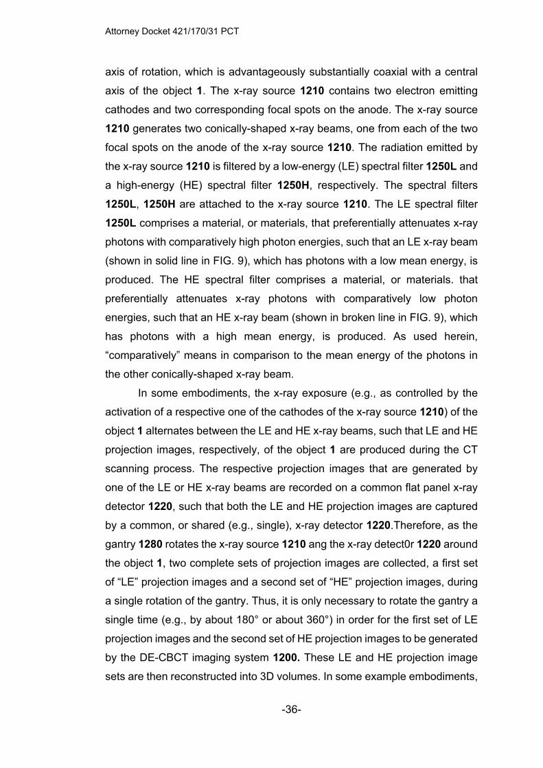
Attorney Docket 421/170/31 PCT
-36-
axis of rotation, which is advantageously substantially coaxial with a central
axis of the object 1. The x-ray source 1210 contains two electron emitting
cathodes and two corresponding focal spots on the anode. The x-ray source
1210 generates two conically-shaped x-ray beams, one from each of the two
focal spots on the anode of the x-ray source 1210. The radiation emitted by
the x-ray source 1210 is filtered by a low-energy (LE) spectral filter 1250L and
a high-energy (HE) spectral filter 1250H, respectively. The spectral filters
1250L, 1250H are attached to the x-ray source 1210. The LE spectral filter
1250L comprises a material, or materials, that preferentially attenuates x-ray
photons with comparatively high photon energies, such that an LE x-ray beam
(shown in solid line in FIG. 9), which has photons with a low mean energy, is
produced. The HE spectral filter comprises a material, or materials. that
preferentially attenuates x-ray photons with comparatively low photon
energies, such that an HE x-ray beam (shown in broken line in FIG. 9), which
has photons with a high mean energy, is produced. As used herein,
“comparatively” means in comparison to the mean energy of the photons in
the other conically-shaped x-ray beam.
In some embodiments, the x-ray exposure (e.g., as controlled by the
activation of a respective one of the cathodes of the x-ray source 1210) of the
object 1 alternates between the LE and HE x-ray beams, such that LE and HE
projection images, respectively, of the object 1 are produced during the CT
scanning process. The respective projection images that are generated by
one of the LE or HE x-ray beams are recorded on a common flat panel x-ray
detector 1220, such that both the LE and HE projection images are captured
by a common, or shared (e.g., single), x-ray detector 1220.Therefore, as the
gantry 1280 rotates the x-ray source 1210 ang the x-ray detect0r 1220 around
the object 1, two complete sets of projection images are collected, a first set
of “LE” projection images and a second set of “HE” projection images, during
a single rotation of the gantry. Thus, it is only necessary to rotate the gantry a
single time (e.g., by about 180° or about 360°) in order for the first set of LE
projection images and the second set of HE projection images to be generated
by the DE-CBCT imaging system 1200. These LE and HE projection image
sets are then reconstructed into 3D volumes. In some example embodiments,
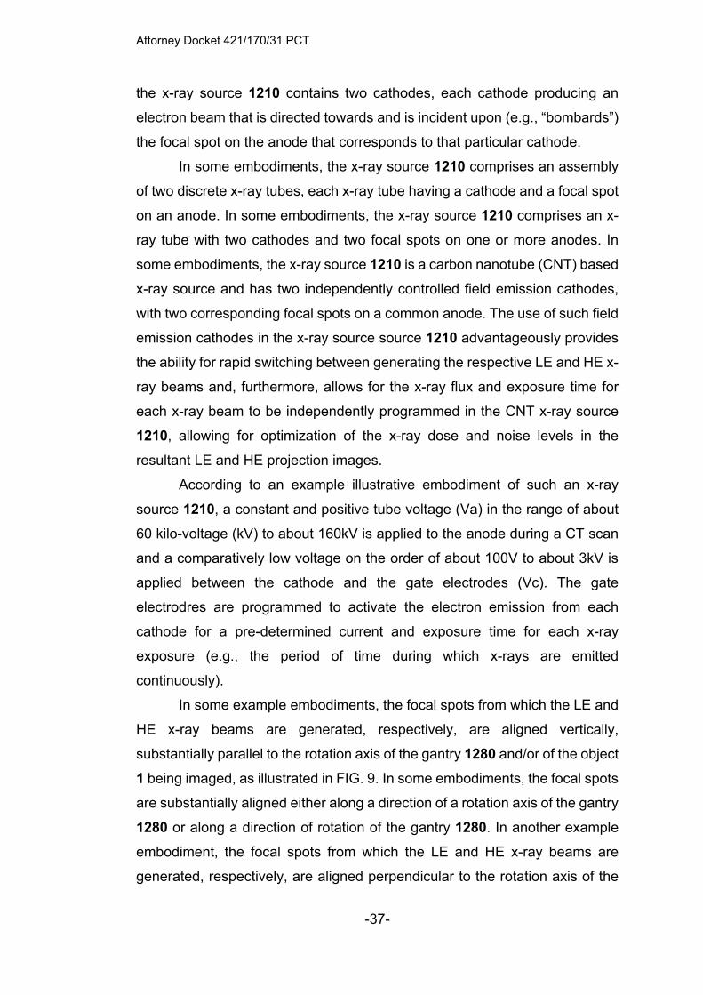
Attorney Docket 421/170/31 PCT
-37-
the x-ray source 1210 contains two cathodes, each cathode producing an
electron beam that is directed towards and is incident upon (e.g., “bombards”)
the focal spot on the anode that corresponds to that particular cathode.
In some embodiments, the x-ray source 1210 comprises an assembly
of two discrete x-ray tubes, each x-ray tube having a cathode and a focal spot
on an anode. In some embodiments, the x-ray source 1210 comprises an x-
ray tube with two cathodes and two focal spots on one or more anodes. In
some embodiments, the x-ray source 1210 is a carbon nanotube (CNT) based
x-ray source and has two independently controlled field emission cathodes,
with two corresponding focal spots on a common anode. The use of such field
emission cathodes in the x-ray source source 1210 advantageously provides
the ability for rapid switching between generating the respective LE and HE x-
ray beams and, furthermore, allows for the x-ray flux and exposure time for
each x-ray beam to be independently programmed in the CNT x-ray source
1210, allowing for optimization of the x-ray dose and noise levels in the
resultant LE and HE projection images.
According to an example illustrative embodiment of such an x-ray
source 1210, a constant and positive tube voltage (Va) in the range of about
60 kilo-voltage (kV) to about 160kV is applied to the anode during a CT scan
and a comparatively low voltage on the order of about 100V to about 3kV is
applied between the cathode and the gate electrodes (Vc). The gate
electrodres are programmed to activate the electron emission from each
cathode for a pre-determined current and exposure time for each x-ray
exposure (e.g., the period of time during which x-rays are emitted
continuously).
In some example embodiments, the focal spots from which the LE and
HE x-ray beams are generated, respectively, are aligned vertically,
substantially parallel to the rotation axis of the gantry 1280 and/or of the object
1 being imaged, as illustrated in FIG. 9. In some embodiments, the focal spots
are substantially aligned either along a direction of a rotation axis of the gantry
1280 or along a direction of rotation of the gantry 1280. In another example
embodiment, the focal spots from which the LE and HE x-ray beams are
generated, respectively, are aligned perpendicular to the rotation axis of the

Attorney Docket 421/170/31 PCT
-38-
gantry 1280 and/or of the object 1 being imagedand are spaced apart from
each other along the rotation direction of the x-ray source 1210 as the gantry
1280 is rotated about the object 1.
In some embodiments, it is advantageous for the LE and HE x-ray
beams to have the same x-ray exposure pre-object or post-object. Since the
HE spectral filter 1250H often attenuates more x-ray photons than the LE
spectral filter 1250L, it is advantageous to set the exposure time for the HE
beam to be longer than the exposure time for the LE beam for each HE
projection image being generated (e.g., at each position about the object 1
where a projection image is generated), so as to maintain a comparable
exposure level between the LE and HE beams. In some embodiments, the
electric current for the x-ray tube that generates the HE beam is greater than
the electric current for the x-ray tube that generates the LE beam.
In an example embodiment, a constant tube voltage in the range of
about 60kVp to about 120kVp is applied to the x-ray source 1210. In one
particular example. the tube voltage is 120 kVp. A flat panel x-ray detector
1210 (FDP) is used to record the projection images. The low energy (LE)
spectral filter 1250L comprises 7mm thick Aluminum (Al) and 0.05mm thick
Gold (Au), which are used in combination to modify the energy spectrum (e.g.,
the mean energy)of the x-ray photons generated from the first, or LE, focal
spot. The high energy (HE) spectral filter 1250H comprises 11mm thick Al and
0.63mm Tin (Sn), which are used in combination to modify the energy
spectrum (e.g., the mean energy) of the x-ray photons generated from the
second, or HE, focal spot.
FIG. 10 shows a simulated x-ray spectra. As shown in FIG. 10, two
distinct energy spectra with about 20keV separation in the mean energies are
produced after the spectral filtration. For dual energy CT imaging, the x-ray
source 1210 and the x-ray detector 1220 rotate in unison around the object 1,
which is held in a stationary, or fixed, position. In one example, the x-ray
source 1210 and the x-ray detector 1220 rotate around the object 1 by about
360 degrees. During the rotation of the x-ray source 1210 and the x-ray
detector 1220 about the object 1, the LE and HE x-ray beams (e.g., radiation
emissions) are activated in an alternating pattern, such that the LE x-ray beam

Attorney Docket 421/170/31 PCT
-39-
is activated for a predetermined exposure time to form an LE projection image
of the object 1 on the x-ray detector 1220 and, after such exposure time has
elapsed, the LE x-ray beam is turned off (e.g., deactivated, de-energized,
etc.); after the LE x-ray beam is turned off, the HE x-ray beam is activated for
a predetermined exposure time to form an HE projection image of the object
1 on the x-ray detector 1220 and, after such exposure time has elapsed, the
HE x-ray beam is turned off (e.g., deactivated, de-energized, etc.). The
process of alternatingly activating and deactivating the LE x-ray beam and the
HE x-ray beam is repeated sequentially until the rotation of the gantry 1280
relative to the object 1 being imaged is completed.
In an example embodiment, 360 LE projection images and 360 HE
projection images are collected over a full rotation of 360° of the gantry 1280
around the object 1 being imaged, with an LE projection image and an HE
projection image being generated for about every 1° of rotation of the gantry
1280 about the object 1. The LE and HE projection images are then processed
and reconstructed to generate the dual energy CT dataset.
As noted elsewhere herein, in an initial feasibility study, a rudimentary
version of the DE-CBCT imaging system 1200 was created and used to
demonstrate the improvements associated therewith over conventional CBCT
imaging systems. During this feasibility study, an anthropomorphic head
phantom (i.e., as object 1) was first imaged by the conventional CBCT imaging
system both before and after a metal bead 10 was attached to the outside
surface of the object 1. FIGS. 11A-D show single energy CBCT images (e.g.,
axial slices of the reconstructed CY image) of the object 1. The image of the
object 1 shown in FIG. 11A was generated using a conventional CBCT
imaging system, without the external metal bead 10 (see, e.g., FIGS. 11B-D)
present. The image of the object 1 shown in FIG. 11B was generated using
the conventional CBCT imaging system after the external metal bead,
generally designated 10, was attached to the object 1. FIG. 11B clearly shown
metal-induced imaging artifacts in the form of dark streaks that are shown as
seemingly radiating away from the metal bead 10 in the reconstructed image
in FIG. 11B. The image of the object 1 shown in FIG. 11C was generated
using the DE-CBCT imaging system 1200 of FIG. 9, using a low activation
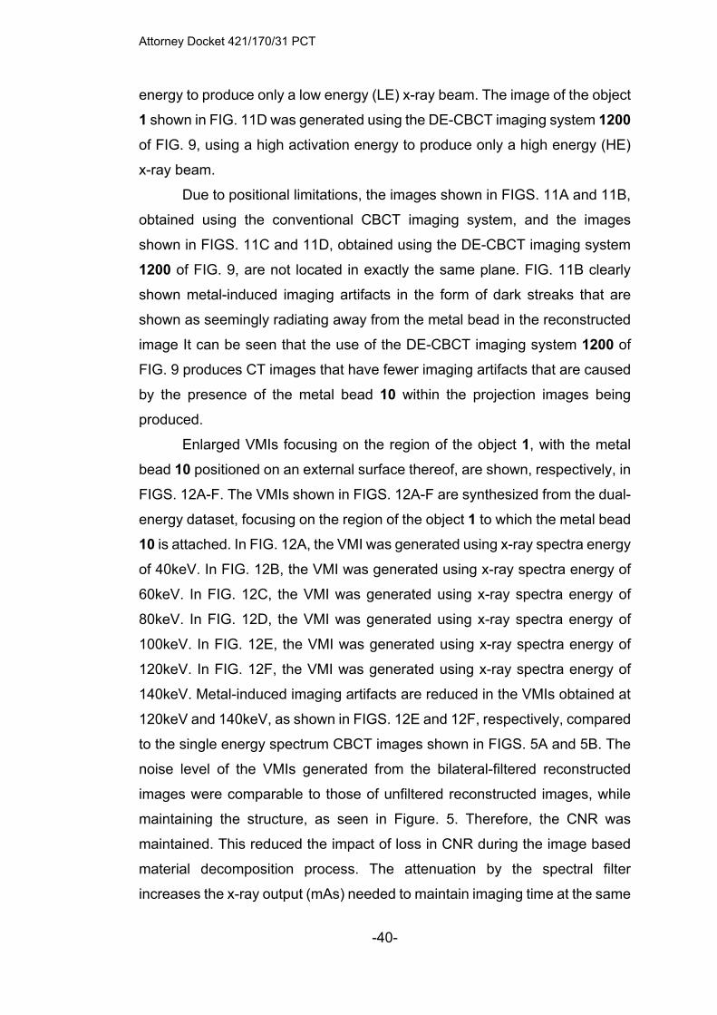
Attorney Docket 421/170/31 PCT
-40-
energy to produce only a low energy (LE) x-ray beam. The image of the object
1 shown in FIG. 11D was generated using the DE-CBCT imaging system 1200
of FIG. 9, using a high activation energy to produce only a high energy (HE)
x-ray beam.
Due to positional limitations, the images shown in FIGS. 11A and 11B,
obtained using the conventional CBCT imaging system, and the images
shown in FIGS. 11C and 11D, obtained using the DE-CBCT imaging system
1200 of FIG. 9, are not located in exactly the same plane. FIG. 11B clearly
shown metal-induced imaging artifacts in the form of dark streaks that are
shown as seemingly radiating away from the metal bead in the reconstructed
image It can be seen that the use of the DE-CBCT imaging system 1200 of
FIG. 9 produces CT images that have fewer imaging artifacts that are caused
by the presence of the metal bead 10 within the projection images being
produced.
Enlarged VMIs focusing on the region of the object 1, with the metal
bead 10 positioned on an external surface thereof, are shown, respectively, in
FIGS. 12A-F. The VMIs shown in FIGS. 12A-F are synthesized from the dual-
energy dataset, focusing on the region of the object 1 to which the metal bead
10 is attached. In FIG. 12A, the VMI was generated using x-ray spectra energy
of 40keV. In FIG. 12B, the VMI was generated using x-ray spectra energy of
60keV. In FIG. 12C, the VMI was generated using x-ray spectra energy of
80keV. In FIG. 12D, the VMI was generated using x-ray spectra energy of
100keV. In FIG. 12E, the VMI was generated using x-ray spectra energy of
120keV. In FIG. 12F, the VMI was generated using x-ray spectra energy of
140keV. Metal-induced imaging artifacts are reduced in the VMIs obtained at
120keV and 140keV, as shown in FIGS. 12E and 12F, respectively, compared
to the single energy spectrum CBCT images shown in FIGS. 5A and 5B. The
noise level of the VMIs generated from the bilateral-filtered reconstructed
images were comparable to those of unfiltered reconstructed images, while
maintaining the structure, as seen in Figure. 5. Therefore, the CNR was
maintained. This reduced the impact of loss in CNR during the image based
material decomposition process. The attenuation by the spectral filter
increases the x-ray output (mAs) needed to maintain imaging time at the same
Attorney Docket 421/170/31 PCT
-41-
total imaging dose as one conventional CBCT scan, especially for the HE
acquisition. The required x-ray output for the DE-CBCT imaging system 1200
was achieved from a fixed-anode CNT x-ray source array. The calculated CT
imaging time for use of the DE-CBCT imaging system 1200 was comparable
to conventional CBCT imaging systems.
The virtual monoenergetic images generated using the DE-CBCT
datasets were effective in reducing effects induced by the presence of metal,
or metal structures, in, on, or around an object 1 being imaged, as shown in
FIGS. 12A-F. For the filtration-based dual energy imaging method disclosed
herein, whether the x-ray source can deliver the increased photon flux needed
to compensate the additional attenuation from the spectral filters to maintain
the imaging time was evaluated. As will be shown elsewhere herein, the
photon flux after spectral filtration and imaging time for the proposed system
is generally comparable to that of conventional CBCT imaging systems.
The effect in which instances of the metal-induced imaging artifacts are
reduced is more pronounced at high virtual monoenergetic energies than low
energies. The attenuation by a spectral filter 1250L, 1250H increases the x-
ray output (mAs) needed to maintain imaging time at the same total imaging
dose as one conventional CBCT scan (e.g., as defined by collection of a
specified quantity of projection images to generate one or more CT images),
especially when the HE filter 1250H is used. The required x-ray output was
achieved from a fixed-anode CNT x-ray source array. The CT imaging time
for the DE-CBCT imaging system 1200 is comparable to the time required for
CT imaging using the conventional CBCT imaging system 103.
An electrical schematic for an example embodiment of a portion of a
DE-CBCT imaging system (e.g., 1200, see FIG. 9), specifically an x-ray
source 1810, of such a DE-CBCT imaging system is shown in FIG. 14.
According to this example embodiment, the x-ray source 1810 comprises an
assembly of two discrete x-ray tubes, each with a cathode 1830 and a focal
spot 1822 on a same (e.g., single) anode 1820. Activation of the cathodes
1830 is controlled by a respective switch 1850, the quantity of switches 1850
advantageously being the same as the quantity of the cathodes 1830. Each
cathode 1830 is connected, via one of the switches 1850, to a low voltage

Attorney Docket 421/170/31 PCT
-42-
power supply 1860. The anode 1820 is connected to a high voltage power
supply 1870, which supplies a higher electric potential (e.g., voltage) than the
low voltage power supply 1860. The cathodes 1830, when activated, emit a
stream of electrons e-, which pass through a focusing region, generally
designated 1840, that focuses the electons e- into an electron beam that
strikes the anode 1820 at a corresponding focal spot 1822.
In some embodiments, the x-ray source 1810 comprises an x-ray tube
with two cathodes 1830 and two focal spots 1822. In some embodiments, the
x-ray source 1810 is a carbon nanotube (CNT) based x-ray source and has
two independently controlled field emission cathodes 1830, with two
corresponding focal spots 1822 on a common (e.g., shared) anode 1820. The
use of such field emission cathodes 1830 in the x-ray source 1830
advantageously provides the ability for rapid switching between the LE and
HE x-ray beams and, furthermore, the x-ray flux and exposure time for each
LE or HE x-ray beam can be independently programmed in the CNT x-ray
source 1810, allowing for optimization of the x-ray dose and noise levels in
the LE and HE projection images.
An electrical schematic for another example embodiment of a portion
of a DE-CBCT imaging system (e.g., 1200, see FIG. 9), specifically an x-ray
source 1910, of such a DE-CBCT imaging system is shown in FIG. 15. As
shown, the x-ray source 1910 comprises two anodes 1920 that are connected
to a common electrical feedthrough (e.g., an electrical connection, or circuit,
which can be connected to a high voltage power supply 1970). Activation of
the cathodes 1930 is controlled by a respective switch 1950, the quantity of
switches 1950 advantageously being the same as the quantity of the cathodes
1930. Each cathode 1930 is connected, via one of the switches 1950, to a low
voltage power supply 1960. Each of the anodes 1920 is connected to a high
voltage power supply 1970, which supplies a higher electric potential (e.g.,
voltage) than the low voltage power supply 1960. The cathodes 1930, when
activated, emit a stream of electrons e-, which pass through a focusing region,
generally designated 1940, that focuses the electons e- into an electron beam
that strikes the anode 1920 at a corresponding focal spot 1922.

Attorney Docket 421/170/31 PCT
-43-
For generating x-ray beams (e.g., LE or HE x-ray beams), a common
electrical potential (e.g., voltage, or voltage difference) is applied between one
of the cathodes 1930 (e.g., by closing one of the switches 1950 to electrically
connect the cathode 1930 to the low voltage power supply 1960) and the
corresponding anode 1920 with which the cathode 1930 is connected. A LE
spectral filter (e.g., 1250L in FIG. 9) is applied to the x-ray radiation emitted
from the first anode (left anode 1920 in FIG. 15) and a HE spectral filter (e.g.,
1250H in FIG. 9) is applied to the x-ray radiation emitted from the second
anode (right anode 1920 in FIG. 15). To further increase the difference in the
average energies of photons in the two (e.g., LE and HE) x-ray beams
generated from the electron beam striking one of the two focal spots 1922 on
the anode 1920, a voltage divider 1980 is electrically connected in series
between the to the first anode 1920 of the x-ray source 1910 and the high
voltage power supply 1970. In an example embodiment, the voltage divider
1980 comprises an electrical resistor, which has a resistance value of R. A
constant electrical potential V is applied between the electrical feedthrough
and the electrical ground. An extraction voltage is applied, via the low voltage
power supply 1960, between the gate electrode and the cathode 1930 and an
electrical current (e.g., electron beam) is received by the first anode 1920. In
this example, the voltage drop across the voltage divider 1980 is expressed
by the equation V = I*R, where I is defined as the electrical current provided
to the X-ray tube and R is defined as electrical resistance. Thus, the electrical
potential between the first anode 1920 and the corresponding cathode 1930
is calculated using the equation ΔV = V-I*R, where V is the electrical potential
between the second anode 1920 and the corresponding cathode 1930 is V,
which is the voltage supplied by the high voltage power supply 1970 to the
second anode 1920.
In the example embodiment shown, the x-ray source 1910 has two
anodes 1920 and two cathodes 1930. Both of the anodes 1920 comprise
Tungsten metal. Both cathodes 1930 are CNT-based field emission cathodes.
Either a common or two separate gate electrodes are used to extract the field
emission electrons from the cathode 1930 by applying a bias voltage between
the gate and the cathode 1930. In this example, a constant high voltage of

Attorney Docket 421/170/31 PCT
-44-
about 90-120kVp is applied to the electrical feedthrough connecting the
anodes 1920 to the high voltage power supply 1970. In one example, the
voltage applied by the high voltage power supply 1970 is about 100kVp and
the voltage divider 1980 is comprises a resistor having a resistance value of
about 2x10⁶ Ohms. For imaging, a bias voltage is applied between the gate
electrode and the cathode 1930 such that a 10mA field emission current, in
the form of an electron stream, is transmitted to the corresponding anode
1920. When the x-ray radiation from the first anode 1920 is activated by the
10mA current, the voltage drop across the resistor of the voltage divider 1980
is about 20kV. The voltage of the first anode 1920 is thereby reduced to about
80kV and the voltage of the second anode is about 100kV. The x-ray radiation
from the first anode 1920 is then filtered by a low energy (LE) spectral filter
(e.g., 1250L in FIG. 9) and the x-ray radiation from the second anode 1920 is
filtered by a high energy (HE) spectral filter (e.g., 1250H in FIG. 9). By
electrically connecting in series a voltage divider 1980 in the form of a resistor
between the first anode 1920 and the high voltage power supply 1970, the
energy separation between the mean, or average, energies of the LE and HE
x-ray spectra is increased. Such an increase the mean energies energy
separation between the mean energies of the LE and HE x-ray spectra is
advantageous for dual energy imaging. In essence, the connection of the
voltage divider 1980 in the form of a resistor between the first anode 1920 and
the high voltage power supply 1970, as shown in FIG. 15, achieves the effect
of the fast kVp switching without actually requiring switching of the voltage
output from the power supply.
FIGS. 16A-C show the simulated x-ray spectra for the DE-CBCT
imaging systems and methods disclosed herein, in comparison to known
technologies under otherwise similar conditions intended for DE-CBCT. The
simulations were performed for 3 cases. In FIG. 16A, kVp switching is
performed at 80kVp and 110kVp and a common, or shared, spectral filter was
used. In FIG. 16B, spectral filtration is performed using LE and HE filters, but
at 110kVp for each anode 1920 (e.g., with the voltage divider 1980 omitted
from the electrical circuit). In FIG. 16C, two different kVp (80/110kVp) are used
to generate LE and HE x-ray beams, respectively, and two different (e.g., LE

Attorney Docket 421/170/31 PCT
-45-
and HE) spectral filters are used. As shown, the post-object average energy
separation of the DE-CBCT systems and methods disclosed herein is about
100% larger (~30keV) compared to the result in either FIGS. 16A or 16B, both
of which are about 16keV. Additionally, the spectral overlap is shown in FIG.
16C is 15%, a reduction of more than 100% as compared to the spectral
overlap in FIG. 16A (36%) and FIG. 16B (54%).
The subject matter disclosed herein demonstrates the feasibility of
performing filter-based DE-CBCT imaging of an object using an x-ray source
with two focal spots operating at the same tube voltage. Metal artifact
reduction was achieved in VMIs synthesized at high energy in phantom
imaging. Additionally, the x-ray output needed for such imaging tasks is shown
herein to be capable of being generated using a fixed-anode CNT x-ray
source.
The present subject matter can be embodied in other forms without
departure from the spirit and essential characteristics thereof. The
embodiments described therefore are to be considered in all respects as
illustrative and not restrictive. Although the present subject matter has been
described in terms of certain specific embodiments, other embodiments that
are apparent to those of ordinary skill in the art are also within the scope of
the present subject matter.
Attorney Docket 421/170/31 PCT
-46-
CLAIMS
1. A volumetric spectral computed tomography (CT) imaging device
comprising:
an x-ray source array comprising M numbers of spatially distributed x-
ray focal spots;
an x-ray beam collimator attached to the x-ray source array, wherein
the x-ray beam collimator contains an array of apertures, each configured to
confine the x-ray radiation from a corresponding x-ray focal spot to illuminate
a corresponding segment of an object to be imaged;
a digital area x-ray detector configured to detect x-ray radiation and
form an x-ray image of the object being imaged, wherein the digital area x-ray
detector is positioned on an opposite side of the object with respect to the x-
ray source array;
a gantry configured to rotate the x-ray source array and the digital area
x-ray detector around the object, wherein the spatially distributed x-ray focal
spots are substantially aligned either along a direction of a rotation axis of the
gantry or along a direction of rotation of the gantry;
an electronic control unit that activates the M numbers of x-ray focal
spots to scan the object N times as the gantry rotates around the object; and
one or more processing systems configured to process the raw N x M
projection images to reconstruct a volumetric CT image of the object.
2. The imaging device of claim 1, wherein radiation from each focal spot
is configured to be filtered by a corresponding spectral filter.
3. The imaging device of claim 1, wherein only a subset of the focal spots
is used to acquire projection images for CT image reconstruction.
4. The imaging device of claim 1, wherein the x-ray focal spots are divided
into a first set and a second set;
wherein x-ray beams from the focal spots in the first set are filtered by
a first filter material(s) configured to yield a spectrum with a first mean x-ray

Attorney Docket 421/170/31 PCT
-47-
photon energy, and x-ray beams in the second set are filtered by a second
filter material(s) configured to yield a spectrum with a second mean x-ray
photon energy, the first mean x-ray photon energy being different from the
second mean x-ray photon energy; and
wherein two sets of projection images acquired from the first set and
the second set are sufficient to reconstruct the volumetric CT image of the
whole object at each distinct x-ray spectrum.
5. The imaging device of claim 4, wherein the first mean x-ray photon
energy is lower than the second mean x-ray photon energy; and
wherein the two sets of projection images captured using the first mean
x-ray photon energy and the second mean x-ray photon energy are processed
to obtain the dual energy CT images of the object.
6. The imaging device of claim 4, wherein the two sets of projection
images are processed to obtain virtual monochromatic energy CT images of
the object at any desired vitural monochromatic energy.
7. The imaging device of claim 1, wherein the x-ray focal spots are divided
into multiple sets wherein x-ray beams from the x-ray focal spots in each set
are filtered by a unique spectral filter to yield a unique x-ray energy spectrum;
wherein the x-ray beams from each set illuminate substantially an
entire field of view (FOV) to generate one complete set of projection images
for CT reconstruction in one gantry rotation; and
wherein multiple sets of projection images at multiple energies are used
for multi-energy CT image reconstruction.
8. The imaging device of claim 1, wherein x-ray beams from the multiple
focal spots are configured to be activated sequentially;
wherein, for each x-ray exposure, a projection image of a
corresponding segment of the object is formed on a corresponding segment
of the digital area x-ray detector; and

Attorney Docket 421/170/31 PCT
-48-
wherein the digital area x-ray detector is configured to reject any x-ray
photons that are recorded outside the corresponding segment of the digital
area x-ray detector as scatter radiation.
9. The imaging device of claim 1, wherein the x-ray source array with
multiple x-ray focal spots is housed in one common and evacuated housing
with either one elongated anode or multiple anodes.
10. The imaging device of claim 1, wherein the x-ray source array is a
carbon nanotube-based field emission x-ray source array.
11. The imaging device of claim 1, wherein an x-ray beam from each focal
spot is configured to cover the object entirely; and
wherein the NxM projection images of the object is configured to be
used for tomographic or tomosynthesis image reconstruction of the object
equivalent to that from a 2D area array of the focal spots.
12. The imaging device of claim 1, wherein the digital area x-ray detector
uses a dynamic region-of-interest (ROI) readout method, to increase a data
readout speed of the digital area x-ray detector;
wherein, after exposure from each collimated x-ray beam, only a
“band,” or ROI, of the digital area x-ray detector that receives primary
transimitted x-ray photons is read by the digital area x-ray detector instead of
the entire detector.
13. The imaging device of claiam 12, wherein a precise location of each
detector band associated with each x-ray source (focal spot) is pre-
determined from the configuration of the imaging system, wherein the
software automatically determines a region of the digital area x-ray detector
to be read for each specific x-ray exposure.
14. The imaging device of claim 1, wherein the NxM projection images are
treated as one complete data set for volumetric CT reconstruction using a
Attorney Docket 421/170/31 PCT
-49-
model-based iterative reconstruction method, wherein locations of the x-ray
focal spots for the NxM projection images are predetermined during system
calibration.
15. The imaging device of claim 1, wherein the reconstructed CT images
are stored in a Digital Imaging and Communications in Medicine (DICOM)
format and can be viewed, analyzed and stored using third party software
packages.
16. A volumetric spectral computed tomography imaging device with
increased contrast resolution and reduced metal-induced imaging artifacts,
the device comprising:
an x-ray source array comprising M numbers of spatially distributed x-
ray focal spots enclosed in a same evacuated housing, wherein the spatially
distributed focal spots are divided into two groups, wherein x-ray radiation
from each group is filtered by a corresponding spectral filter material to
produce a distinct energy spectrum;
an x-ray beam confining device attached to the x-ray source array,
wherein the x-ray beam confining device comprises:
an array of apertures, each configured to confine x-ray radiation
from a corresponding x-ray focal spot to form a fan beam shape with a
narrow cone angle that illuminates a corresponding segment of an
object,
wherein radiation from each group of focal spots collectively
cover an entire field-of view (FOV);
a digital area x-ray detector;
a gantry configured to rotate the x-ray source array and the digital area
x-ray detector around the object;
an electronic control unit configured to activate the M numbers of x-ray
focal spots, one or more beams at a time, to scan across the object N times
as the gantry rotates around the object, and configured to read out an image
recorded on a corresponding area of the digital area x-ray detector and

Attorney Docket 421/170/31 PCT
-50-
configured to reject scattered x-ray photons received outside an area of the
digital area x-ray detector for each x-ray exposure; and
one or more processing systems configured to process the projection
images formed by radiation exposure from each group of focal spots to
reconstruct two volumetric CT image datasets of the object, each volumetric
CT image dataset taken at a different mean x-ray photon energy, the one or
more processing systems being further configured to synthesize virtual
monoenergetic CT image datasets at desired energy levels with reduced
metal-induced imaging artifacts;
wherein the spatially distributed x-ray focal spots are substantially
aligned along a direction of the gantry rotation axis.
17. A method for performing volumetric spectral computed tomography
(CT) imaging of an object, the method comprising:
providing a volumetric spectral computed tomography imaging device
comprising:
an x-ray source array comprising M numbers of spatially
distributed x-ray focal spots;
an x-ray beam confiner attached to the x-ray source array,
wherein the x-ray beam confiner contains an array of apertures, each
configured to confine the x-ray radiation from a corresponding x-ray
focal spot to a fan beam having a narrow cone angle that illuminates a
corresponding segment of the object to be imaged;
a digital area x-ray detector configured to detect x-ray radiation
and form an x-ray image of the object being imaged, wherein the digital
area x-ray detector is positioned on an opposite side of the object with
respect to the x-ray source array; and
a gantry configured to rotate the x-ray source array and the
digital area x-ray detector around the object, wherein the spatially
distributed x-ray focal spots are substantially aligned along a direction
of a rotation axis of the gantry;
activating the M numbers of x-ray focal spots to scan the object N times;
Attorney Docket 421/170/31 PCT
-51-
rotating the gantry around the object while the x-ray focal spots are
activated;
filtering radiation from each focal spot by a corresponding spectral filter;
and
processing, using one or more processors, N x M projection images to
reconstruct a volumetric CT image of the object.
18. The method of claim 17, further comprising using only a subset of the
focal spots to acquire projection images for CT image reconstruction.
19. The method of claim 17, wherein the x-ray focal spots are divided into
a first set and a second set;
wherein x-ray beams from the focal spots in the first set are filtered by
a first filter material configured to yield a spectrum with a first mean x-ray
photon energy, and x-ray beams in the second set are filtered by a second
filter material configured to yield a spectrum with a second mean x-ray photon
energy, the first mean x-ray photon energy being different from the second
mean x-ray photon energy; and
wherein two sets of projection images acquired from the first set and
the second set are sufficient to reconstruct the volumetric CT image of the
whole object at each distinct x-ray spectrum.
20. The method of claim 19, wherein processing the N x M images
comprises processing images captured using the first mean x-ray photon
energy and images captured using the second mean x-ray photon energy to
obtain a single volumetric CT image of the object.
21. The method of claim 19, wherein the first mean x-ray photon energy is
lower than the second mean x-ray photon energy; and
wherein the two sets of projection images captured using the first mean
x-ray photon energy and the second mean x-ray photon energy are processed
to obtain the dual energy CT images of the object.
Attorney Docket 421/170/31 PCT
-52-
22. The method of claim 19, wherein the two sets of projection images are
processed to obtain one or more virtual monochromatic energy CT images of
the object at any desired energy.
23. The method of claim 17, wherein the x-ray focal spots are divided into
multiple sets wherein x-ray beams from the x-ray focal spots in each set are
filtered by a unique spectral filter to yield a unique x-ray energy spectrum; and
wherein the x-ray beams from each set illuminate substantially an
entire field of view (FOV) to generate one complete set of projection images
for CT reconstruction in one gantry rotation.
24. The method of claim 17, further comprising sequentially activating x-
ray beams from the multiple focal spots;
wherein, for each x-ray exposure, a projection image of a
corresponding segment of the object is formed on a corresponding segment
of the digital area x-ray detector; and
wherein the digital area x-ray detector is configured to reject any x-ray
photons recorded outside the corresponding segment of the digital area x-ray
detector as scatter radiation.
25. The method of claim 17, wherein the x-ray source array with multiple
x-ray focal spots is housed in one common and evacuated housing with either
one elongated anode or multiple anodes.
26. The method of claim 17, wherein the x-ray source array is a carbon
nanotube-based field emission x-ray source array.
27. The method of claim 17, wherein an x-ray beam from each focal spot
is configured to cover the object entirely; and
wherein the NxM projection images of the object is configured to be
used for tomographic or tomosynthesis image reconstruction of the object
equivalent to that from a 2D area array of the focal spots.
Attorney Docket 421/170/31 PCT
-53-
28. A dual-energy computed tomography (CT) imaging device comprising:
an x-ray generator comprising an x-ray source, which has at least one
cathode and at least one anode and is configured to emit x-ray radiation from
first and second focal spots for imaging an object, and first and second
spectral filters, wherein the first spectral filter is configured to filter the x-ray
radiation from the first focal spot to produce low-energy (LE) x-ray radiation
with a low mean energy, and wherein the second spectral filter is configured
to filter the x-ray radiation from the second focal spot to produce high-energy
(HE) x-ray radiation, the HE x-ray radiation having a higher mean energy than
the LE x-ray radiation;
an x-ray beam collimator that is configured to confine the LE x-ray
radiation and the HE x-ray radiation to substantially a same region of interest
on, in, and/or about the object;
an x-ray detector configured to detect x-ray radiation and form an x-ray
image of the object, wherein the x-ray detector is positioned on a different side
of the object relative to the x-ray source;
a gantry configured to rotate the x-ray source and the x-ray detector
around the object;
a controller that is configured to:
activate the LE x-ray radiation and the HE x-ray radiation
multiple times in an alternating exposure pattern as the x-ray source
and the x-ray detector are rotated about the object, such that an LE
projection image of the object is recorded by the x-ray detector for each
exposure of the LE x-ray radiation and an HE projection image of the
object is recorded by the x-ray detector for each exposure of the HE x-
ray radiation; and
activate and program an exposure level of the LE x-ray radiation
and an exposure level of the HE x-ray radiation, wherein the exposure
level of the LE x-ray radiation is independent of the exposure level of
the HE x-ray radiation; and
one or more processing systems configured to reconstruct dual-energy
CT images of the object using the LE projection images and the HE projection
images.
Attorney Docket 421/170/31 PCT
-54-
29. The imaging device of claim 28, wherein the at least one cathode of the
x-ray source comprises at least first and second cathodes, each of which is
configured to emit electrons in a form of an electron beam, wherein the at least
one anode comprises one anode or two separate anodes, wherein the first
and second focal spots are on the common anode or the two separate anodes,
wherein the first cathode is positioned such that the electron beam emitted is
incident on the first focal spot, and wherein the second cathode is positioned
such that the electron beam emitted is incident on the second focal spot.
30. The imaging device of claim 29, wherein the first and second anodes
are connected to a common electrical feedthrough.
31. The imaging device of claim 30, comprising a device, which is
electrically connected to the first anode to reduce an electrical potential
between the first anode and the first cathode compared to an electrical
potential between the second anode and the second cathode when a same
electrical potential is applied to the x-ray generator through the electrical
feedthrough by a power supply.
32. The imaging device of claim 31, wherein the device is an electrical
resistor.
33. The imaging device of claim 31, wherein the electrical resistor is
connected in series with the first anode to reduce an energy of the x-ray
radiation emitted from the first anode.
34. The imaging device of claim 28, wherein the at least one cathode is an
electron field emission cathode.
35. The imaging device of claim 28, wherein the at least one cathode is a
carbon nanotube-based electron field emission cathode.

Attorney Docket 421/170/31 PCT
-55-
36. The imaging device of claim 28, wherein the controller is configured to
independently program the exposure level of the LE x-ray radiation and the
exposure level of the HE x-ray radiation to have a substantially similar imaging
dose to reduce image noise.
37. The imaging device of claim 28, wherein the at least one anode
comprises at least a first anode and a second anode, the first anode
comprising a different anode material from the second anode material, such
that the first and second anodes generate two distinct x-ray spectra.
38. A multi-energy computed tomography (CT) imaging device comprising:
an x-ray source, which has at least one cathode and at least one anode
and is configured to emit x-ray radiation from a plurality of focal spots for
imaging an object;
a plurality of spectral filters, each of which is positioned such that the
x-ray radiation emitted from each of the plurality of focal spots is filtered by a
corresponding one of the plurality of spectral filters to produce radiation with
a unique spectrum;
an x-ray beam collimator that is configured to confine the x-ray radiation
emitted from each of the plurality of focal spots to substantially a same region
of interest on, in, and/or about the object;
an x-ray detector configured to detect x-ray radiation and form an x-ray
image of the object, wherein the x-ray detector is positioned on a different side
of the object relative to the x-ray source;
a gantry configured to rotate the x-ray source and the x-ray detector
around the object;
a controller that is configured to:
activate the x-ray source to provide the x-ray radiation from one
of the plurality of focal points multiple times in a sequential exposure
pattern as the x-ray source and the x-ray detector are rotated about the
object, such that a projection image of the object is recorded by the x-
ray detector for each exposure of the x-ray radiation; and
Attorney Docket 421/170/31 PCT
-56-
activate and program an exposure level of the x-ray exposures
from one or more of the plurality of focal spots sequentially, wherein
the exposure level of each of x-ray radiations is independent of others
of the x-ray radiations; and
one or more processing systems configured to reconstruct multi-energy
CT images of the object using the projection images.
39. The imaging device of claim 38, wherein the at least one cathode
comprises a plurality of electron field emission cathodes and the at least one
anode comprises a plurality of anodes.
40. The imaging device of claim 39, wherein each anode of the plurality of
anodes is connected to an electrical resistor configured to adjust an electrical
potential between the anode to which the electrical resistor is connected and
a corresponding one of the plurality of cathodes.
41. The imaging device of claim 38, comprising an electrical resistor that is
connected in series between an anode of the at least one anode and a power
supply, the electrical resistor being configured to reduce an electrical potential
provided to the anode to which the electrical resistor is connected.
42. The imaging device of claim 41, wherein the controller is configured to
vary a resistance of the electrical resistor to vary the electrical potential
provided to the anode to which the electrical resistor is connected as a function
of the resistance.
43. The imaging device of claim 42, wherein the electron beam focusing
structure for each of the at least one cathode is configured such that the
plurality of focal spots have a substantially similar focal spot size while the
electrical potential between the anode, to which the electrical resistor is
connected, and a corresponding cathode of the at least one cathode is varied
by the controller.

Attorney Docket 421/170/31 PCT
-57-
ABSTRACT OF THE DISCLOSURE
A multisource volumetric spectral computed tomography imaging
device includes an x-ray source array with multiple spatially distributed x-ray
focal spots, an x-ray beam collimator with an array of apertures, each
confining the radiation from a corresponding x-ray focal spot to illuminate a
corresponding segment of an object, a digital area x-ray detector, and a gantry
to rotate the x-ray source array and the detector around the object. An
electronic control unit activates the radiations from the x-ray focal spots to
scan the object multiple times as the gantry rotates around the object. The
images are used to reconstruct a volumetric CT image of the object with
reduced scattered radiation. For dual energy and multi energy imaging,
radiation from each focal spot is filtered by a corresponding spectral filter to
optimize its energy spectrum.