Embed Size (px)
Citation preview

Electronic component
Electronic component:
An electronic component is any basic discrete device or
physical entity in an electronic system used to affect
electrons or their associated fields.
Department of ELECTRONICS AND COMMUNICATION ENGINEERING, SMIT
2
TYPES OF COMPONENTS PASSIVE COMPONENTS:
Components capable of dissipation and storage of energy.
They do not require external source for their operation.
Eg: Resistors, Capacitors, Inductors etc
ACTIVE COMPONENTS:
The components in which transformation of Energy takes place
They are having the capability of processing a signal its own.
They need external source for their operation.
They have power gain
Eg: Diode, Transistors etc Department of ELECTRONICS AND COMMUNICATION ENGINEERING, SMIT
3
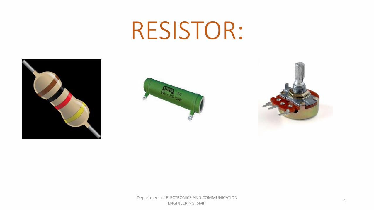
RESISTOR:
Department of ELECTRONICS AND COMMUNICATION ENGINEERING, SMIT
4
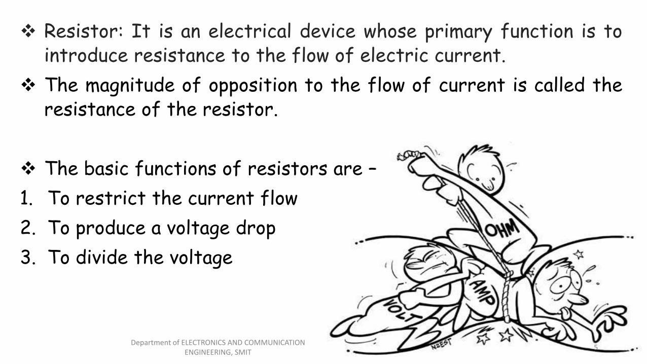
Resistor: It is an electrical device whose primary function is tointroduce resistance to the flow of electric current.
The magnitude of opposition to the flow of current is called theresistance of the resistor.
The basic functions of resistors are –
1. To restrict the current flow
2. To produce a voltage drop
3. To divide the voltage
Department of ELECTRONICS AND COMMUNICATION ENGINEERING, SMIT
5
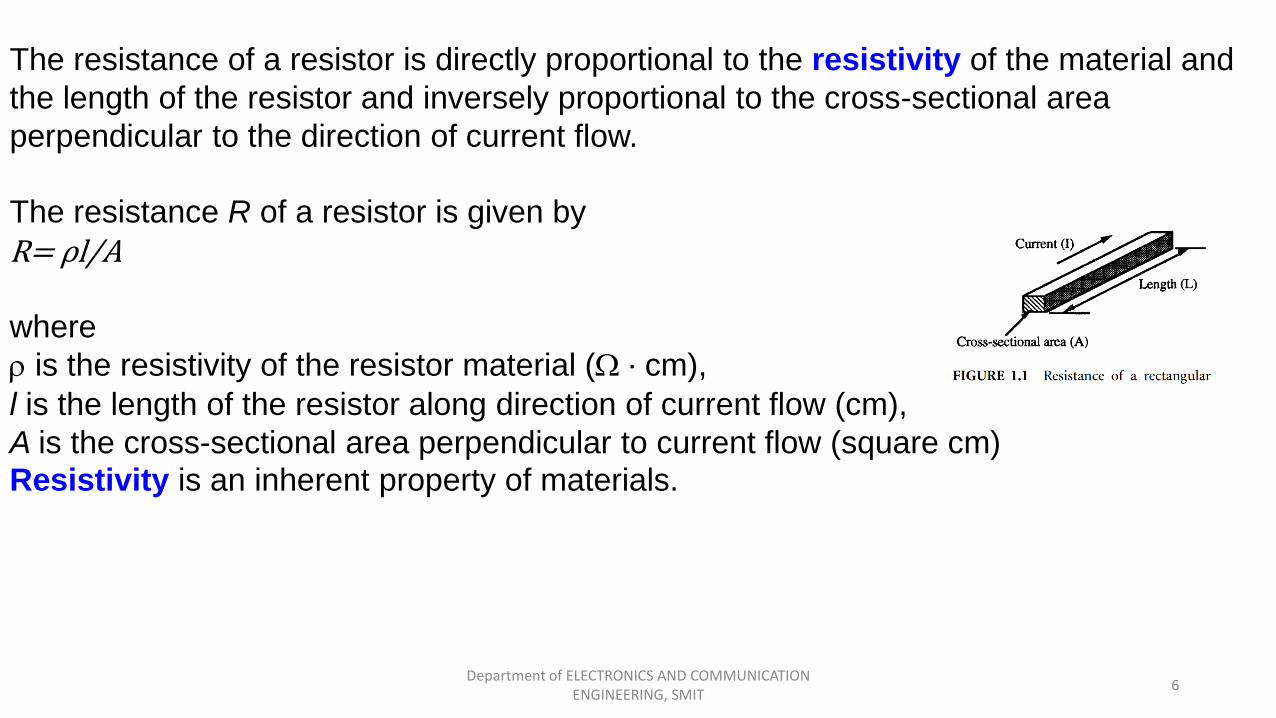
Resistor Characteristics:
The resistance of a resistor is directly proportional to the resistivity of the material and
the length of the resistor and inversely proportional to the cross-sectional area
perpendicular to the direction of current flow.
The resistance R of a resistor is given by
R= ρl/A
where
r is the resistivity of the resistor material (W · cm),
l is the length of the resistor along direction of current flow (cm),
A is the cross-sectional area perpendicular to current flow (square cm) Resistivity is an inherent property of materials.
Department of ELECTRONICS AND COMMUNICATION ENGINEERING, SMIT
6
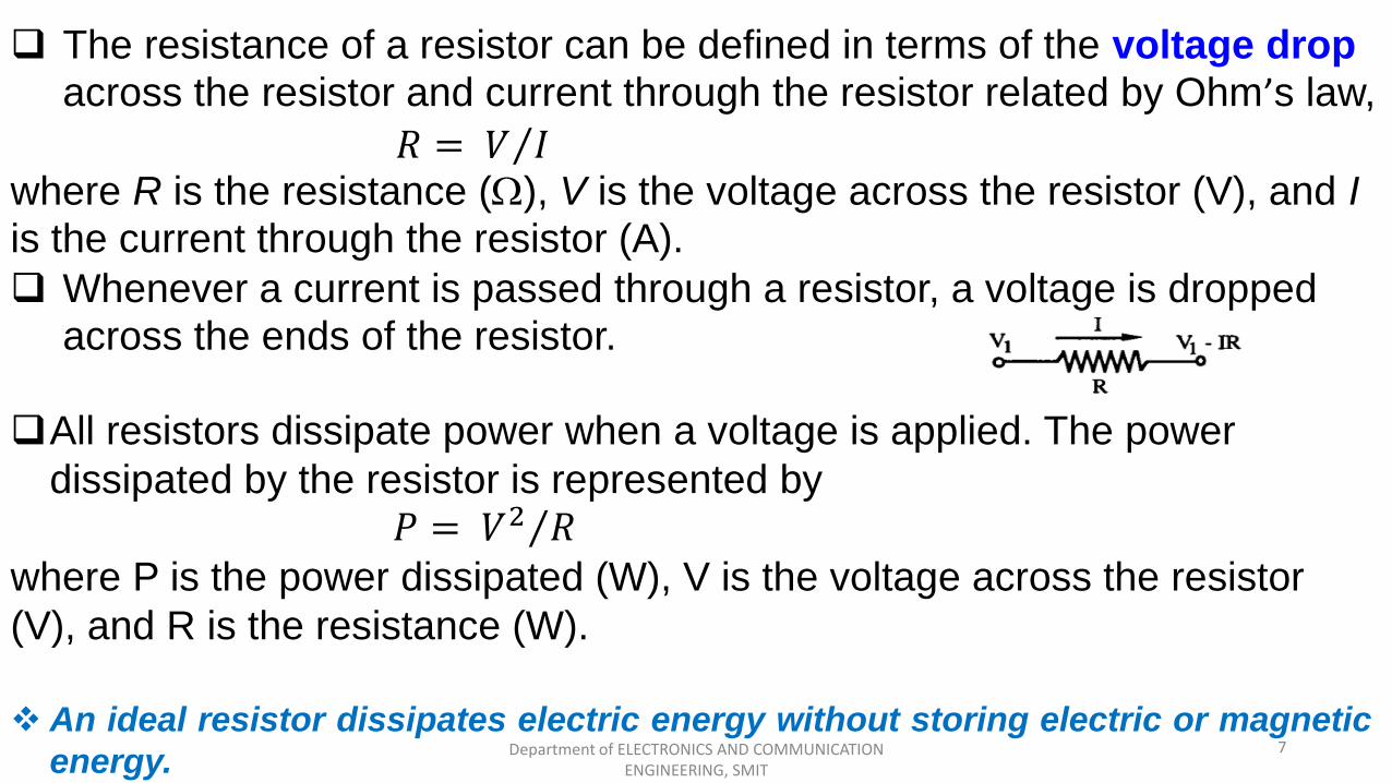
All resistors dissipate power when a voltage is applied. The power
dissipated by the resistor is represented by
where P is the power dissipated (W), V is the voltage across the resistor
(V), and R is the resistance (W).
An ideal resistor dissipates electric energy without storing electric or magnetic
energy.
The resistance of a resistor can be defined in terms of the voltage drop across the resistor and current through the resistor related by Ohm’s law,
where R is the resistance (W), V is the voltage across the resistor (V), and I is the current through the resistor (A).
Whenever a current is passed through a resistor, a voltage is dropped across the ends of the resistor.
𝑃 = 𝑉2 𝑅
𝑅 = 𝑉 𝐼
Department of ELECTRONICS AND COMMUNICATION ENGINEERING, SMIT
7
Department of ELECTRONICS AND COMMUNICATION ENGINEERING, SMIT
8
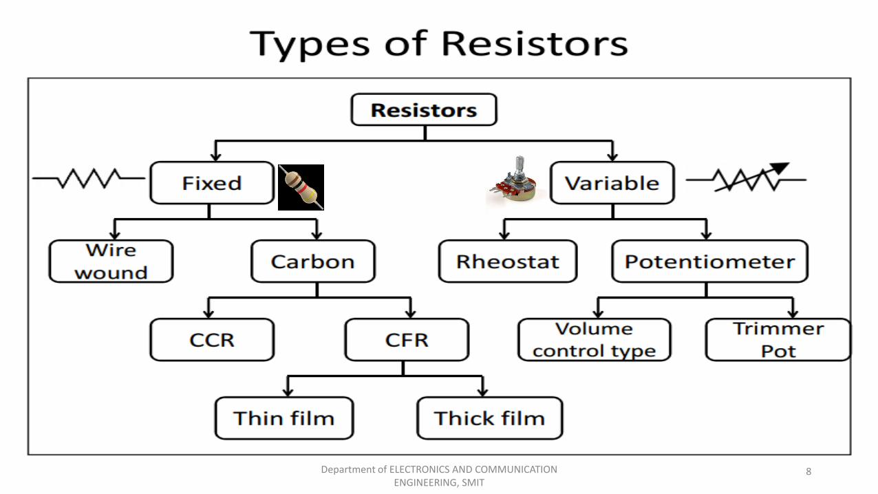
Fixed Resistors:
The fixed resistors are those whose value cannot be varied after manufacture. Fixed resistors are classified intocomposition resistors, wire-wound resistors, and metal-film resistors.
Types:
Wire Wound ResistorCarbon Resistor
Department of ELECTRONICS AND COMMUNICATION ENGINEERING, SMIT
9
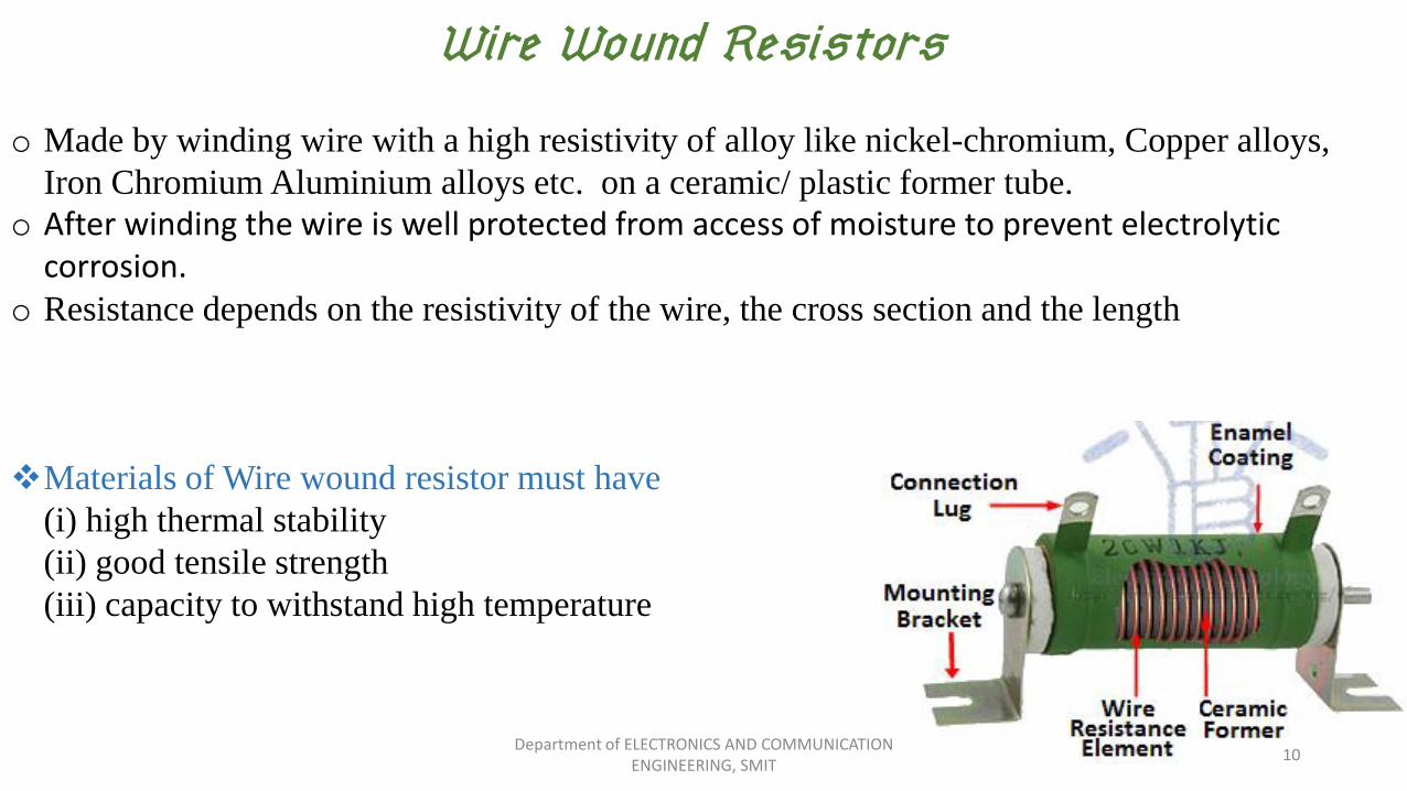
Wire Wound Resistors:
o Made by winding wire with a high resistivity of alloy like nickel-chromium, Copper alloys,
Iron Chromium Aluminium alloys etc. on a ceramic/ plastic former tube.
o After winding the wire is well protected from access of moisture to prevent electrolytic corrosion.
o Resistance depends on the resistivity of the wire, the cross section and the length
Materials of Wire wound resistor must have
(i) high thermal stability
(ii) good tensile strength
(iii) capacity to withstand high temperature
Department of ELECTRONICS AND COMMUNICATION ENGINEERING, SMIT
10
Characteristics of wire wound resistors:
Accurate resistances with low tolerances
Withstand large power dissipation
High accuracy
Withstand mechanical shock and vibration
Can carry large current
Not suitable for high frequency
Costly
Department of ELECTRONICS AND COMMUNICATION ENGINEERING, SMIT
11
Carbon Resistors
o Carbon in amorphous form conducts current. o In Carbon resistors, finely ground carbon dust or graphite (conductor) is bound with a
nonconducting ceramic powder (binder)o The ratio of carbon dust to ceramic (conductor to insulator) determines the overall
resistance of the mixture- Higher the ratio of carbon, lower the overall resistance
o Types: Carbon Composition Resistor (CCR) Carbon Film Resistor (CFR)
Department of ELECTRONICS AND COMMUNICATION ENGINEERING, SMIT
12
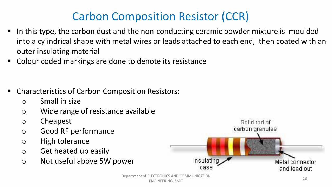
Carbon Composition Resistor (CCR) In this type, the carbon dust and the non-conducting ceramic powder mixture is moulded
into a cylindrical shape with metal wires or leads attached to each end, then coated with an outer insulating material
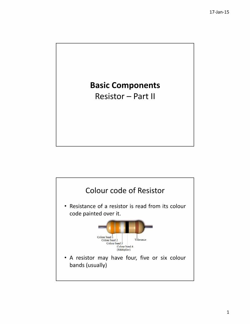
Colour coded markings are done to denote its resistance
Characteristics of Carbon Composition Resistors:o Small in sizeo Wide range of resistance availableo Cheapesto Good RF performanceo High toleranceo Get heated up easilyo Not useful above 5W power
Department of ELECTRONICS AND COMMUNICATION ENGINEERING, SMIT
13
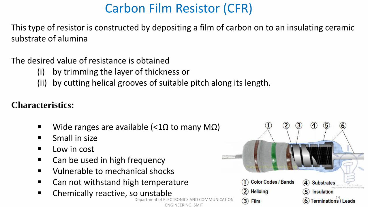
This type of resistor is constructed by depositing a film of carbon on to an insulating ceramic substrate of alumina
The desired value of resistance is obtained(i) by trimming the layer of thickness or(ii) by cutting helical grooves of suitable pitch along its length.
Characteristics:
Wide ranges are available (<1Ω to many MΩ) Small in size Low in cost Can be used in high frequency Vulnerable to mechanical shocks Can not withstand high temperature Chemically reactive, so unstable
Carbon Film Resistor (CFR)
Department of ELECTRONICS AND COMMUNICATION ENGINEERING, SMIT
14
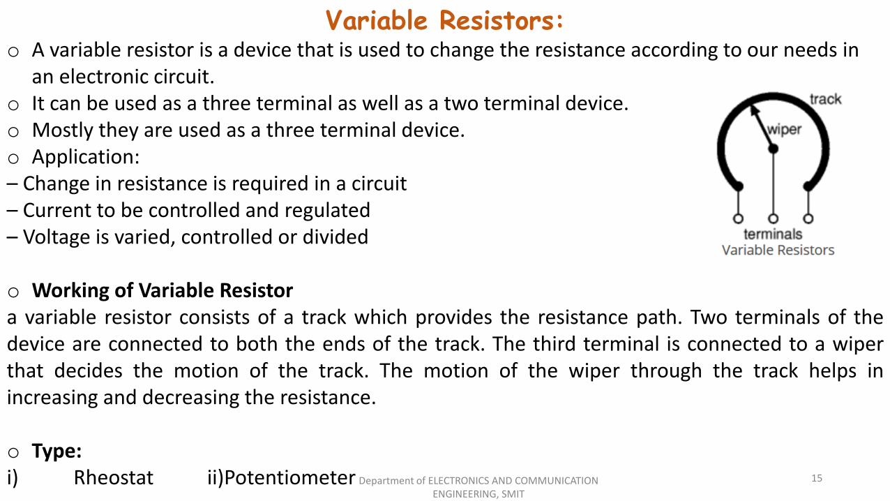
Variable Resistors: o A variable resistor is a device that is used to change the resistance according to our needs in
an electronic circuit. o It can be used as a three terminal as well as a two terminal device. o Mostly they are used as a three terminal device. o Application:– Change in resistance is required in a circuit– Current to be controlled and regulated– Voltage is varied, controlled or divided
o Working of Variable Resistora variable resistor consists of a track which provides the resistance path. Two terminals of thedevice are connected to both the ends of the track. The third terminal is connected to a wiperthat decides the motion of the track. The motion of the wiper through the track helps inincreasing and decreasing the resistance.
o Type:i) Rheostat ii)Potentiometer Department of ELECTRONICS AND COMMUNICATION
ENGINEERING, SMIT
15
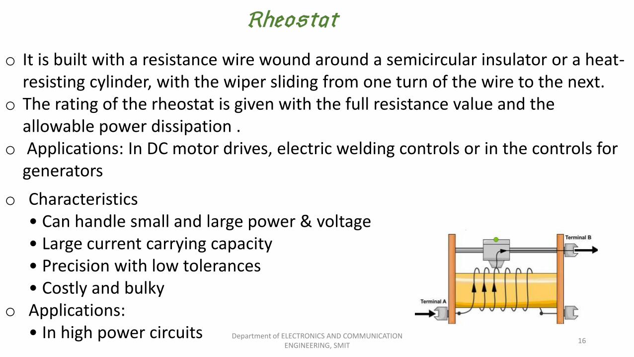
Rheostat:
o It is built with a resistance wire wound around a semicircular insulator or a heat-resisting cylinder, with the wiper sliding from one turn of the wire to the next.
o The rating of the rheostat is given with the full resistance value and the allowable power dissipation .
o Applications: In DC motor drives, electric welding controls or in the controls for generators
o Characteristics• Can handle small and large power & voltage• Large current carrying capacity• Precision with low tolerances• Costly and bulky
o Applications:• In high power circuits Department of ELECTRONICS AND COMMUNICATION
ENGINEERING, SMIT16
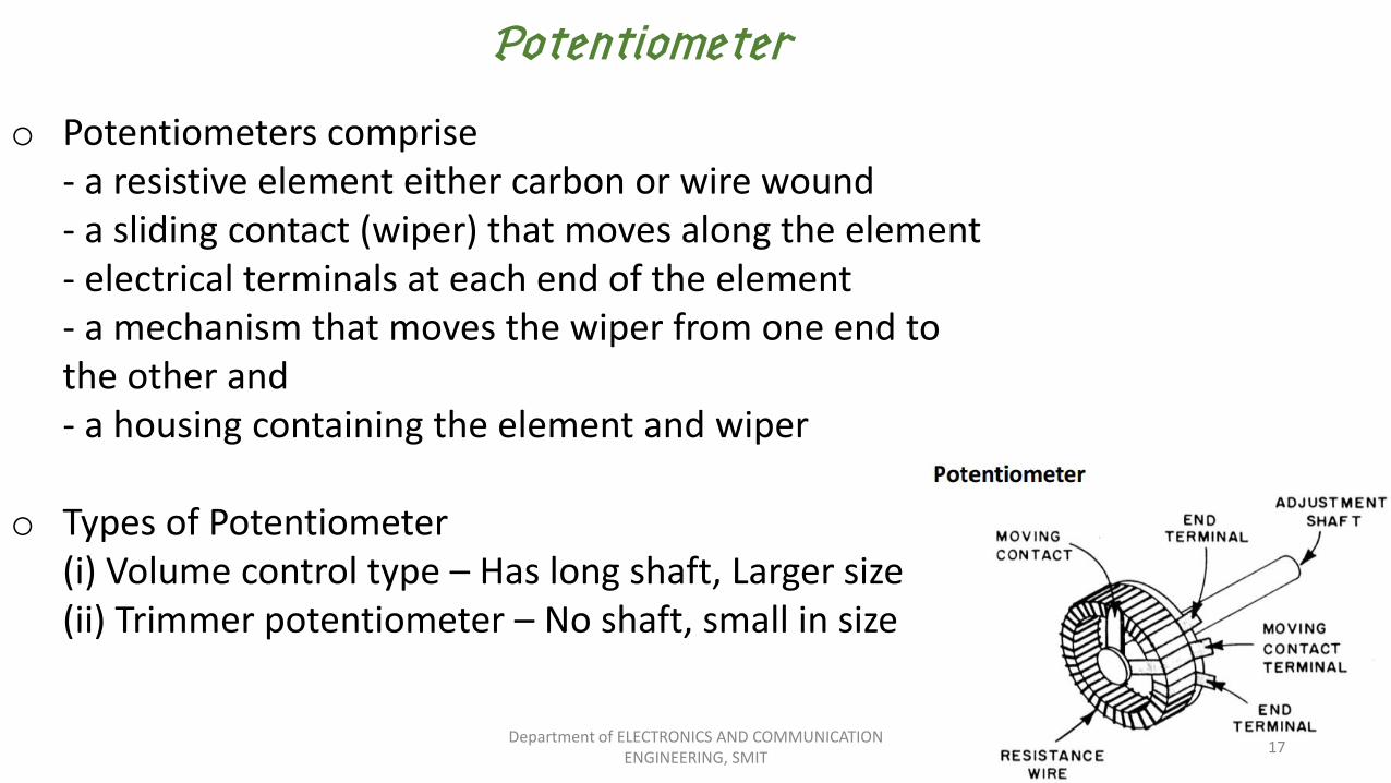
o Potentiometers comprise- a resistive element either carbon or wire wound- a sliding contact (wiper) that moves along the element- electrical terminals at each end of the element- a mechanism that moves the wiper from one end tothe other and- a housing containing the element and wiper
o Types of Potentiometer(i) Volume control type – Has long shaft, Larger size(ii) Trimmer potentiometer – No shaft, small in size
Potentiometer:
Department of ELECTRONICS AND COMMUNICATION ENGINEERING, SMIT
17
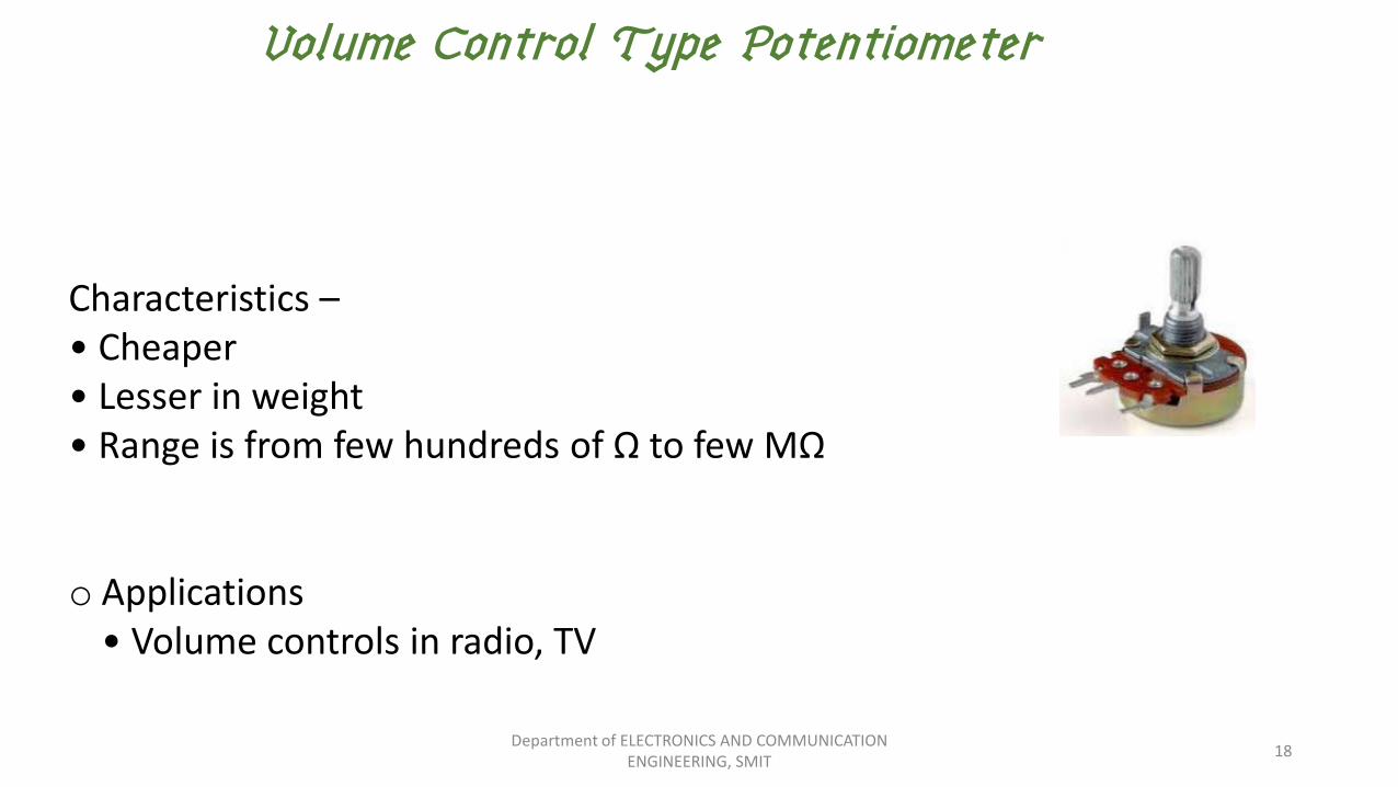
Characteristics –• Cheaper• Lesser in weight• Range is from few hundreds of Ω to few MΩ
o Applications• Volume controls in radio, TV
Volume Control Type Potentiometer
Department of ELECTRONICS AND COMMUNICATION ENGINEERING, SMIT
18
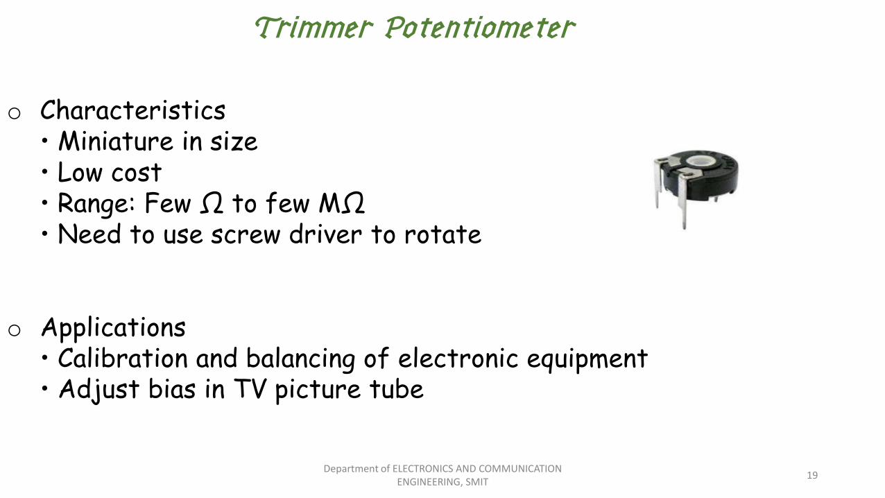
Trimmer Potentiometer
o Characteristics• Miniature in size• Low cost• Range: Few Ω to few MΩ• Need to use screw driver to rotate
o Applications• Calibration and balancing of electronic equipment• Adjust bias in TV picture tube
Department of ELECTRONICS AND COMMUNICATION ENGINEERING, SMIT
19
Components of an electrical circuit or electronic circuit can be connected in many different ways.
The two simplest of these are:seriesparallel.
Department of ELECTRONICS AND COMMUNICATION ENGINEERING, SMIT
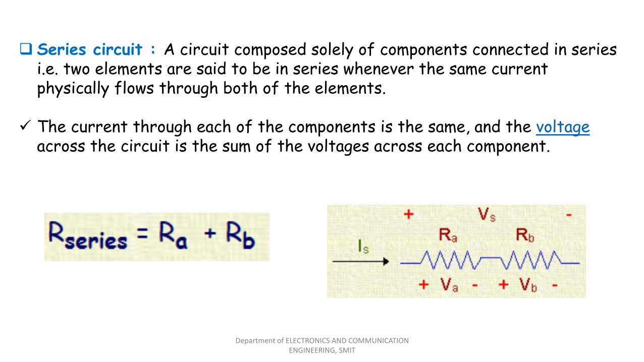
Series circuit : A circuit composed solely of components connected in series i.e. two elements are said to be in series whenever the same current physically flows through both of the elements.
The current through each of the components is the same, and the voltageacross the circuit is the sum of the voltages across each component.
Department of ELECTRONICS AND COMMUNICATION ENGINEERING, SMIT
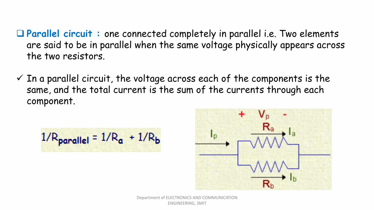
Parallel circuit : one connected completely in parallel i.e. Two elements are said to be in parallel when the same voltage physically appears across the two resistors.
In a parallel circuit, the voltage across each of the components is the same, and the total current is the sum of the currents through each component.
Department of ELECTRONICS AND COMMUNICATION ENGINEERING, SMIT