Embed Size (px)
Citation preview
BEElMIL-HDBK-540030 NOVEMBER 1995SUPERSEDINGMIL-STD-540015 JUNE 1992
MILITARY HANDBOOKELECTRONIC EQUIPMENT, AIRBORNE
GENERAL GUIDELINES FOR
. .
\
THIS HANDBOOK,IS FOR ~GUIDANCEoNLy. DO NOT CITE.THIS DOCUMENTAS A REQUIREMENT.
AMSC NIA AREA”GDRQDISTRIBUTION STATEMENT A. Approved for public release; distributionis unlimited.
I
MIL-HDBK-5400
FOREWORD
1. This military handbook is approved for use by al1 Departments and Agenciesof the Department of Defense.
2. Beneficial comments (recommendations, additions, deletions) and any,,
pertinent data which may “be of use in improving this document should beaddressed to: Commander, Systems Standardization, Code 4.1.4.2B120-3,. NavalAir Warfare Center Aircraft Oivision, Highway 547, Lakehurst, NJ OB733-S1OO, .by using the self-addressed Standardization Oocument Improvement Proposal (DOForm 1426) appearing at the end of this document or by “letter.
3. This handbook provides guidance for implementing and tailoring guidelinesand documents contained in MIL-HDBK-454 Standard General Guidel ines forElectronic Equipment, which have applicability in the design and production ofelectronic equipment for airborne applications. Included in this handbook arereference’s to the applicable requirements, an index of applicable documents,and a guide for tailoring and application of those requirements and documentsin conjunction with ‘the various equipment design, development and productionphases.
ii

MIL-HDBK-5400
PARAGRAPH
I 11.11.1.11.1.21.21.2.1
2.2.12.22.3
3.73.83 .“9 “.3.103.113.123.133.143.15
4.4.14.1.14.1.2
4.1.34.24.2.14.2.24.2.34.2.44.2.54.2.64.2.74.2.7.14.2.7.2
CONTENTS
~
SCOPE . . . . . . . . . . . 1Scope”nj::.nll:Rnj:: . . . . . . . . ..’.1Application . . .. . ...’... .. . . . . . . ...1Tailoring . . . . . . . . . . . . . . . . . . . ...1Class ification . . . . . . . . . . . . . . . . . ...1External cooling . . . . . . . . . . . . ..’.. ...2
APPLICATION OOCUMENTi . . . . . . . . . . . . . . ...2Documents . . .. . . . . . . . . . . . . . 2Appli~able~s~Uis”::.... ,. . . . . . . ... ...2Copies . . . . . ...”..... . . . . . . . . ...2
DEFINIT,IONS . . . . . . . . . . . . . . . . . . . ...2Accessory . . . . . . . . . . . . . . . . 2Ac~j~iti,on”a~t~v~t~ : . . . . . .,. . . . . . . . . . 2Airborne . . . . . . . . . . . . . . . . . . . . . ...2Complete operating equipment . . . . . . . . . . . . . 2Detail specification....’.. . . . . . . . . ...3Electron ice . . . . . . . . . . .... . . . . . . . . . .Equipment . . . . . . . . . .Hermeticseal;ngnlj:Ju~: 1 . . . . . . . ...3Instal1ation (complete equipment) . . . . . . 3Intermittent and short time operati& “ : 1 ,. . . : . . ;Other component definitions .. . . . .Performance requirements of tie “equ{prne~t“ J . . . . . 4Permanently installed part,”. . . . . . . . . . . . . . 4Removable assembly.....’.. . . . . . . . . ...4Reordered production equipment . . : . . . . . . . . .-4
GENERAL GUIDELINES . . . .. ... . . . . ...”... ..4Untitled . . . . . . . . . . .. . . . . . . . . ...4Tailoring of MIL-HDBK-454 guidelines : . . . . . . . . 4Standard hardware acquisition and reliability
program (SHARP) 4Requirements,, table: ~nd ~igu;e~ 1 1 j : : 1 1 j 1 1 1 5Design and construction . . . ,.,. . . . . . . . . . . 5.Untitled .’. . . . . . . . . . . .‘. . . . . . . ...5Accessibility . . . . . . . . . . 5Anti-jamming.llI~J1ll 11 . . . . . . . . . ..”5Castings, metal 6Corona and electr~c~l “b;e;kdown “p~e~e;t~o; : : I 1 n : 6Derating .. . . . . . . . . . . . . . . . . .. . ...7Electrical overload protection . . . . . . . . . . . . 7Resettable circuit protectors . . . . . . . . . . . “.7Spare fuses . . . . . . . . . . . . . . . . . . ...7
iii
MIL-HDBK-5400
PARAGRAPH
4.2.84.2.8.14.2.8.24.2.94.2.104.2.114.2.11.14.2.11.24.2.124.2.134.2.144.2.154.2.15.1,4.2.164.2.174.2.17.14.2.17.24.2.17.34.2.184.2.194.2.204.2.214.2.224.2.234.2.23.14.2.23.24.2.23.34.2.24,4.2.254.2.264.2.274.2.27.14.2.27.24.2.284.2.28.14.2.28.2;.; .;;.3
4:2:304.2.30.14.2.314.2.31.14.2.31.2
CONTENTS, (continued)
~
Electrical power . . . . . . . . . . . . . . . . ...7Warm-upt ice. ... . . . . . . . . . . . . . . . ..’.7Untitled . . . . . .. . . . . . . . . . . . . . ...7Electromagnetic interference control . . . . . . . . . 7Electrostatic discharge control . . . . . . . . . . .. 7Enclosures. . . . . . .. . . . . . . . . . .. . ....8Standardized avionics enclosures . . . . . . . . . . . 8
‘ Other enclosures . . . . . ... . . . . . .’.......Fabrication . . . . . . . . . . . . . . . . . . . .. .Grounding, bonding and shielding . . . . . . . . . . . 8
,“Human,engi neering . : . . . . . . . . . . . . . .. ..8Interchangeabi lity . . . . . . . . . . . . . . . . ...8Interchangeability of reordered equipment . ,. . . . . 8Maintainabil icy . . . . . . . . . . . . . . . . ...9Marking . . . . . . . . . 9
/. Labels.~:IR::IuIIIJ :: . . . . . . ...9Wire coding for identification . . . . . . . . . . . . gOperational programmarking . .. . . . . . . . . . . gIiicrophonias . . . . . . . . . . . . . . . . . . ...9Moisture pocket s....... . . .. . . . . . . ...9Multi flexing....,...’., . . . . .. ..~o. ..~oNomenclature assignment . . . . . . . . . . . . . . .Orientation . . . . . . . . . . . . . . . . . . ...10’Panels . ... . . . . . ... . . . .: . . . . . . ...10Control panels . . . . . . . . . . . . . . . . . ...10Electroluminescent panels . . ... . . . . . . . . . . 10Ranges.of adjustable parts . . . . . . . . . . . . . . 10Pressurizati on . . . . . . . . . . . . . . . . . ...10Reliability . . . . . . . . . . . . . . . . . . ...11~;~~a;abil icy . . . . . . . . . ...,...’.....~~
. . . . . . . . . . . . . . . .System;a~e<y”III;..... . . . . . . . ...-12Personnel safety . . . . . . . . . . . . . . . . ...12Test provisions .:..,.... . . . . . . . . . . . 12Built- in test devices . . . . . . . . . . . . . . . . 12External test points . . . . .. . . . . . . . . . ...12
“.Failure effect . . . . . . .. .“......-.....12Testability program . . . . .“. . . . . . . .. . ..12Thermal design . . . . . . . . . . . . . . . . . ...13Cooling design data . . . . . . . . . . . . . . . . .13Tool S . . . . . . . . . . . . . . . .“13Setscrew wr~n~hes”l E..... . . . . . . . . ...13Specialt oils. . . . . . . .. . . . . . . . . . ...13
.,
iv

MIL-HDBK-5400
4.2.31.34.2.324.2.33.4.34.3.14.3.1.14.3.24.3.34.3.44.3.4.14.3.4,.2
4.3.4.34.3.4 .3.14.3.4.44.3.4.5 \“4.3.5 ‘4.3.64.3.74.3.84.3.8.14.3.8.24.3.94.3.9.14.3.9.24.3.9.34.3.104.3.10.14.3.10.24.3.10.34.3.11.4.3.124.3.134.3.144.3.154.3.164.3.174.3.17.14.3.17.24.3.17.34.3.184.3.18.14.3.18.24.3.18.3
I 4.3.18.4I
CONTENTS (continued)
~
Furnishing and stowing . . . . . ‘. : . . . . . . . . . 13Standardized power supplies . . . . . . . . . . .,. . 13Workmanshipp . . . . . . . . . . . . . . . 13Parts selecti;n”:j; j.... . . . . . . . ...114Government furnished baseline (GFB) . . . . . . . . . 14Choice of parts . . . . . . . . . . . . . . . . ...14Nonstandard parts . . . . . . 14Parts control progr;m” J 1 :’: J I :.: ; I . . . . . . 14Approval of parts 16.Contracts under cat~g&~ ~ : 1 : : : 1 1 : n : 1 1 : I 16Contracts for equipment which fall under categories
IIand III . . . . . . . . . . . . . . . . . . ...16Reordered production equipment ... . . . . . . . . . ..16Continuation of production . . . . . . . . . . . . . . 16Replacing of approved parts . . . . . . . . . . . . . 17Equipment performance . . . .,~ . . . . . . . . . . . 17Substitute on of parts . . . . . . .. . . . . . . . .17Batteries . . . . . . . . . . . . . . . . . . . ...178earings . . . . . . . . . . . . . . . . . . . ....17-Capacitors . . . . . . . . . . . . . . . . . . . ...1.?Fixed, “tantalum, electrolytic . . . . . . . . . ‘. . . 1?Aluminum electrolytic . . . . . . . . . . . . . . .. 17Circuit breakers ..:...... . .. . . . . . . ...17”Manual operation .’....... . . . . . . . . ...17Position identification . . . . . . . . . . . . . . . 18Orientation . . . . . ...”.. . . . . . . . . . ...18Connectors, electrical .“,.. . . . . . . . . . . . “. . 18Mounting. of electrical receptacles . . . . . . . . . . 18.Adjacent locations . . . . . . “.. . . . . . . . . ..~~JacksControl; ~k;obs; ha;die;, “d;aisi E : j I J I : 1 I j “118Crystals (quartz and oscillator) . . . . . . . . . .“. 18,Fastener hardware . . . ... . . . .. . . . . . . ..18Filters, electrical . . .Fuses, fuseholders and as;o~iated “h~rdw~re ; j j . . . ::Gears . . . . . . . .. . . . . . . . . . . . . ...19Hydraul ice . . . . . . .. . .... . . . . . . . . . ...19
Aircraft . . . .. . . . . . . . . . . . . . . . ...19Missiles..........’. . . . . . . . . . ...19Untitled . . . . . . . . . . . . ..” . . . ..’ ....19Lights and associated items . . . . . . . . . . . . “. 19Indicator lights . . . . . . . . . . . . . . . . ...19Press to test indicator lights . . . . . . . . . . . 19Instrument lights . . . . . . . . . . . . . . . ...19Lamps . . . . . . . . . . . . . . . . . . . . . ...19
v

MIL-HDBK-5400
CONTENTS (continued)
PARAGRAPH
4.3.18.54.3.18.64.3.194.3.204.3.214.3.21.14.3.21.24.3.224.3.22.14.3.22.24.3.234.3.244.3.254.3”.264.3.274.3.27.14.3.27.24.3.27.34.3.28“4.3.294.3.304.3.30.14.3.30.1.14.3.30.1.24.3.314.3.31.14.3.31.24.3.31.34.3.324.?..334.3.344.3.354.3.35.14.3.35.24.3.35.34.3.35.44.3.35.54.3.35.6
::1.14.4.24.4.34.4.44.4.4.1
I 4.4.5.
EM
Visual display and legend lights . . . . . . . . . . . 20Night v“isioncompatibility . . . . . . . . . . . . . . 20Meters . . . . . . . . . . . . . . . . . . . . . .. ’.20Microelectronic devices . . . . . . . . . . .. . . . . ~~Motors . . . . . . . ...”... . . . . . . . . . . .Motors, alternating current . . . . . . . . . . . . . 20Motors, direct current . . . . . . . . . . . . . ...20“Readouts and displays . . . . . . . . . . . . . ...20Readouts . . . . . . . . . . . . . . . . . . . . ...20.Display s . . . . . . . . . . . . . . . . . . . . ...20Relays . . . . . . .. . . . . . . . . . . . . . . ...20Resistors . . ... . . . . . . . . . . . . . . . ...20.Semiconductor devices . . . . . . . . . . . . . . . . 21Servodevices, rotary . . . . . . . . . . . . . . ...21Sockets, shields and mounting pads . . . . . . . . . . 21
) Sockets . . . . . . . . . . . . .. . . . . . . ...21Shields . . . . . . . . . . . . . . . 21Mounting~ads”lIH:J.... . . . . . . . ..’ ..21SpringsStandard ilec~r&{c ”modul~s’(5EMs)’ 1 I H : : : : : : ; ;;Switches . . . . . ... . . . . . . . . . . . . ...21Mounting . . . . . . . . . . . . . . . . . . . . ...21Rotary switches . . . . . . . . . . . . . . . . ....21Toggle switches . . . . . . . . . . . . . . . . ...21Terminations . . . . . . . . . . . . . . . . .....22Number of wires per terminal or lug . . . . . . . . . 22Number of lugs per terminal” . . .’. . . . . . . . . . 22Number of wires in a connector contact . . . . . . . ~ 22Transformers, inductors and coils . . . . . . . . . . 22Tubes, electron: . . . . . . . . . . ... . . . . ...22Waveguides and related item: . . . . . . . . . . . . . 22Wire and cable . . . . . . . . . . . . . . . . . ...22Wire andcable, internal . . . . . . . . . . . . ...22Wiring practices, internal . ... . . . . . .. . . . . . 2?Wire and cable, external interconnection . . . . . . . 23External wiring practices . . . . . . . . .. . . . . . 23Cable, coaxial (RF) . . . . ... .. . . . . . . . . .~~.Printed wiring . . . . . . . . ~ . . . . . . . . . . .Material selection . . . . . . . . . . .. . . . ...23Choice of materials . . . . . 23Polyvinyl chloride (PVC)’rna~e;i;l~ : n H ; j . . . . . 24Standard materials....... . . . . . . . . ...24Nonstandard materials . . . . . . . . . . . . . . - . 24Approval of nonstandard materials . . . . . . . . . . 24Adhesives . . . . . . . . . . . . . . . . . . . ...24
vi

MIL’HDBK-5400
CONTENTS (continued)
PARAGRAPH
4.4.64.4.74.4.84.4.94.4.104.4.114.4.124.4.134.4.14‘4.4.15.4.54.5.14.5.1 ..14.5.1.24.5.l.2.l\4.5.1.2.2’4.5.1 .2.34.5.24.5.34.5.44.5.4.14.5.4.2:.:.4.”3
4:6.14.6.1.14.6.24.6.2.14.6.2.1.14.6.2 .1.24.6.2.24.6.2.34.6.2.44.6.2.54.6.2 .5.14.6.2 .5.1.1
4.6.2.5.1.24.6.2 .5.1.34.6.2 .5.1.44.6.2.64.6.2 .6.14.6.2 .6.24.6.2 .6.34.6.2.7
Arc-resistant materials . . . . . . . . . . . . . . . 25”Nonformal coating . . . . . . . . . . . . . . ..’ ..25Dissimilar material s...... . . . . . . . . ...25Encapsulation and embedment materials . . . . . . . . 24Fibrous material, organic . . . . “. . . . . . .. . . . 25Flammability of materials . . . . . . 25Fungus-inert materials . . : : : : : : : : . . . . . . 25Insulators, insulating and dielectric materials . . . 25Lubricants . . . . . . . . . . . . . . . . . . . ...25Metals, corrosion resistant . . . . . . .Processes and finishes ...:: : : ::....... ;2Protective platings and coatings . . . . . . . . . . . 26Material s . .. . . . . . . . . . . . . . . . . ...26Aluminum alloy . . . . . . . . . . . . . . . . . ...26Surface i general. . . . . . . .... . . . . . . . . .. 26.Surfaces, bonded and grounded ,.. . . .Surfaces, extreme wear”resistan~ : : : : : . . . . . . ;;Magnesium and magnesium alloys . . . . . . . . . . . “.26Zinc and zinc-plated parts . . . . . . . . . . . . . 2EFinishes . . . . . . . . . . . . .. . ....-....28Cases and front panels..... . . . . . . . . ...28Fasteners and assembly screws . . . . . . . . .. . . . ~’Other standard finishes . . . . . . .Environmental service requi;erne;t~ : : : . . . . . . . 28MIL-STD-81O environmental tests . . . . . . . . . . . 28Untitled . . . . . . . ... . . . . . . . . . . . ..2gEquipment operational requirements . . . . . . . . . . 29Temperature . . . . . . . . . . . . . . . . . . ...2gOperating . . . . . . . . . . . . . . . . . . 29Nonoperating: ::....... . . . . . . . . ...29Altitude . . . . . ...’.... . . ..~ . . . ...35Temperature-altitude combination . . . . . . . . . . . 35Humid icy . . . . . . . . . . . . . . . . . . . . ...35VibrationEquipment norrnail~,rno~n~ed: : : : : : : : : : : : :::;Equipment designed for install ation in propeller
aircraft . . . . . . ...” . . . . . . . . . . ...35Equipment designed for installation in jet aircraft . 35Equipment designed for installation in helicopters . . 35Minimum integrity test..... . . . . . . . . ...35Shock . . . . . . . 36Equiprne&.”::::’::::::: :::: . . . . ...36Mounting base (crash safety) . . . . . . . . . . . . 36Bench handling . . . . . . . . . .. . . . . . . . ...36Sand and dust . . . . . . . . . . . . . . . . . ...36
vii
MIL-HDBK-5400
PARAGRAPH
4.6.2.84.6.2.94.6..2.10
::1
H5.3.15.3.25.3.35.3.45.3.55.3.6‘5.3.6.15.3.75.4
6.6.16.2
FIGURES
1
2
3
4
IM4Ls
I11IIIIVv
CONTENTS (continued)
m,.
Fungus . . . . . . . . . . . . . . . . ..”. ”. . ...36Salt atmosphere . . . . . . . . . . . . . . . . ..’ .36Explosive conditions . . . . . . . . . . . . . . ...36
6ETAILGU10ELINE5 .. . ... . . . . . .. . . . ..”. .. 37”Oetailed mechanical and electrical design . .‘. . . . 37”Technical data . . . . . . . . . . . . . . ..” . ...37Quality assurance . ... . . . . . . . . . . . . . . 37Responsibility for tests and inspections . . . . . . . 37Government verification . . . . . . . . . . . . . . . 37Failure criteria . . . . . . . . . . . . . . .. . ..” .37Problem/failure reporting and corrective action . . . 38Oesign qualification tests . . . . . . . . . . . . . . 38First article tests . . . . . . . . . . . . . . . ..3BScope ob tests . ... . . . . . . . . . . . . . . ...38
> QUality, conformance tests . . . . . . . . . . . . . . 38’Preparation for delivery . . . . . L . . . . . . . . . 39
NOTES . . . . . . . . . . . .‘. 39Intended l~si: :::::::.. . . . . . . . . ...39Oetails for inclusion in equipment specifications
and contracts .”...... . . . . . . . . . ...39Use of helium . . . . . . . . . . . . . . . ...40Publications . ::....... . . . . . . . . ...41Subject term (keyword) listing . . . . . . . . . . . . 41
Operational requirements for class 1 airborne >electronic equipment (temperature vs altitude) . . . ..31
Operational requirements for”class 2 airborneelectronic equipment (temperature vs altitude) . . . . 32
Operational requirements for class 3 airborneelectronic equipment (temperature vs altitude) .:. . . 33
Operational requirements for class 4 airborneelectronic equipment (temperature vs altitude) . . . . 34
General design and construction . . . . . . . . . . . . 6Parts selection . . . . . . . .Material sselectio~ ”::::: : : : : :........ ;:Processes and finishes . . . . . . . . . . . . . . .. . .27Environmental conditions . . . . . . . . . . .’. . . . . 30
. . .Vlll

MIL-HDBK-5400
CONTENTS (continued )
~
APPENDIX A APPLICABLE DOCUMENTS . . . . . . . . . . . .“~ : . . . . A-1APPENDIX B “SAMPLE TAILORING GUIDE . . . . . . . . . . . . . . . .. B-1
INDEX . . . . . . . . . . . . . . . . . .. . . . . . . . . . 1-1
,
.,
ix

MIL-HDBK-5400
1. SCOPE
1.1 &Q&. This handbook contains general guidelines fOr .SleCtrOniC”equipment for operation in piloted aircraft and helicopters, missiles,boosters and al1ied vehicles. Oetail electrical and mechanical design,performance and test requirements should be as specified in the det’ailspecification or contract. This handbook is for guidance only. This handbookcannot be cited as a requirement. If it is, the contractor does not have tocomply.
1.1.1 Aoo7ication. This handbook should not be invoked on a blanketbasis; however, each guideline should be assessed in terms of need. Thishandbook is a compendium of general guidelines, the majority of which havebeen selected from MIL-HOBK-454, for specific applicability to airborneelectronic equipment. Individual detail specifications or contract shouldinvoke only those requirements which are applicable and necessary to thatspecif(ic equipment’.
1.1.2 Tailorinq. A tailoring guide, Appendix B, is included to assistthe acquisition activity and the contractor in’applying MIL-HDBK-5400guidelines to the various phases of equipment design, development andproduction.
1.2 Classification. Suggested” classification for design and manufactureof electronic equipment is as fol10WS (see 6.2).
Class 1 -
Class lA-
Class lB-
Class 2 -
Class 3 -
I
Equipment designed for 15.20 km (50,000 feet) altitudeand continuous sea level operation over the temperaturerange of -54° to +55°C (+71°C intermittent O.pf!ratiOn).
Equipment designed for 9.12 km (30,000 feet) altitude andcontinuous sea level operation over the temperature rangeof -54° to +55°C (+71°C intermittent operation).
Equipment designed fo’r4.56 km (15,000 feet) altitude andcontinuous sea level operation over the temperature rangeof -40° to +55°C (+71°C intermittent operation).
Equipment designed for 21.28 km (70,000 feet) altitudeand continuous sea level. operation over the temperaturerange of -54° to +71°C (+95°C intermittent operation).
Equipment designed for 30.40 km (100,000 feet) altitudeand continuous sea level operation over the temperature .’range of -54° to +95°C (+125°C intermittent operation):
1
Class 4 - Eauioment desianed for 30.40 km (100~000 feet) altitudeaid continuous-sea level operati~n o~er the “temperaturerange of -54° to +125°C (+150°C intermittent operation).
1
MIL-HDBK-5400
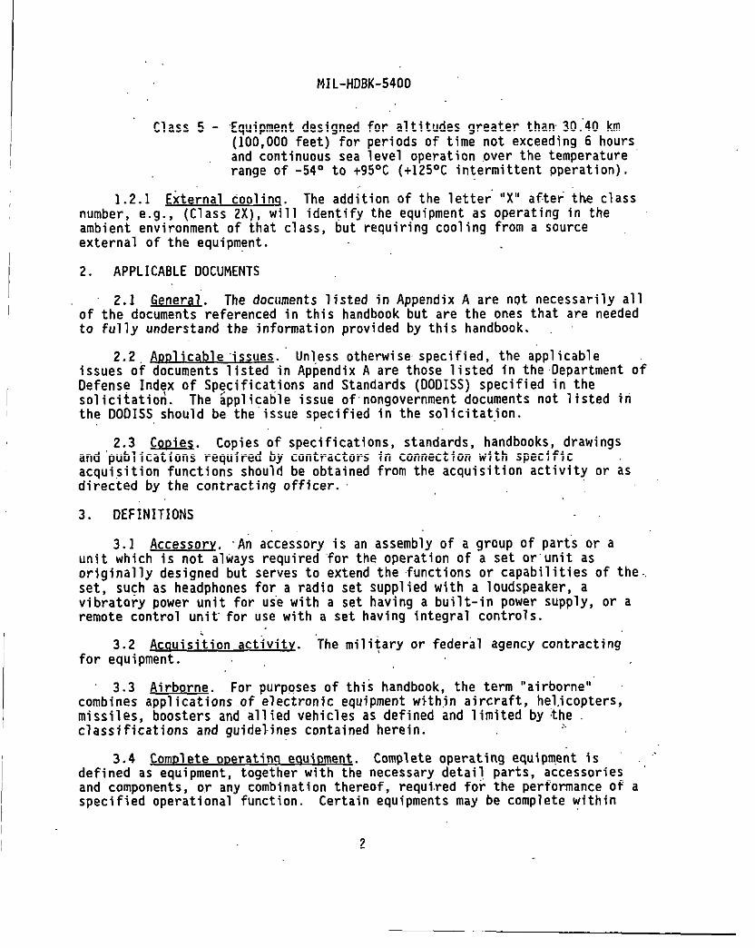
Class 5 - Equipment designed for altitudes greater than 30.’40 km(100,000 feet) for periods of time not exceeding 6 hoursand continuous sea level operation over the temperaturerange of -54° to +95°C (+125°C intermittent pperation).
1.2.1 External coolinq. The addition of the letter “X” after the classnumber, e.g. , (Class 2X), will identify the equipment as operating in theambient environment of that class, but requiring cooling from a sourceexternal of the equipment.
2. APPLICABLE DOCUMENTS
2.1 General The documents 1isted in Appendix A are ngt necessarily allof the doc=~eferenced in this handbook but are the ones that are neededto fully understand the information provided by this handbook.
2.2 A~. Unless otherwise specified, the applicableissues of documents 1isted in Appendix A are those 1isteal in the Department ofDefens@ Index of Sp~cifications and Standards (OODISS) specified in thesolicit atioti. The applicable issue of nongovernment documents not 1isted irithe DODISS should be the issue specified in the solicitation.
2.3 m. Copies of specifications, standards, handbooks, drawingsand “publications required by contractors in connection with specificacquisition functions should be obtained from the acquisition activity or asdirected by the contracting officer.
3. DEFINITIONS
3.1 Accessory. ‘An accessory is an assembly of a group of parts or aunit which is not always required ‘for the operation of a set or”unit asoriginally designed but serves to extend the functions or capabilities of the..set, such as headphones for a radio set suppl ied with a loudspeaker, avibratorv Dower unit for us”ewith a set havinq a built-in Power SUPPIY, or aremote c~ntrol unit for use with a set having-integral controls.
3.2 Acau ‘isition activity. “The military or federal agency contractingfor equipment.
3.3 Airborne,. For purposes of this handbook, the term “airborne”combines appllcatlons of electronic equipment within aircraft, helicopters,missiles, boosters and allied vehicles as defined and 1imited by theclassi fications and guidelines contained herein.
3.4 ComDl ete oDeratinq eauiDment. Complete operating equipment isdefined as equipment, together with the necessary detail, parts, accessoriesand components, or any combination thereof, required for the performance ofspecified operational function. Certain equipments may be complete within
a
2
MIL-HDBK-5400
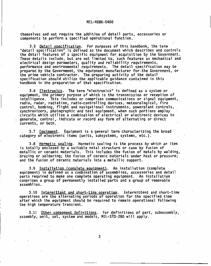
themselves and not require the addition of “detail parts, accessories orcomponents to perform a specified operational function.
3.5 ~. For purposes of this.handbook, the term“detail specification” is defined as the document which describes and controlsthe @etail features of a specific equipment for, acquisition by the Government.These details include, but “are not 1imited,to, such features as mechatiical andelectrical design parameters, quality and reliabil ity requirements,performance and environmental requirements. The detail specification may beprepared by the Government, the equipment manufacturer for the Government, orthe prime vehicle contractor. The preparing activity of the detailspecification should util ize the applicable guidance contained in thishandbook in the preparation of that specification.
3“.6 Electronics. The term “electronics” is defined as a system orequipment, the primary purpose of which is the transmission or reception ofintelligence. This” includes or comprises communications or signal equipment,radio, radar, radiation, radio-control 1ing devices, meteorological, firecontrol, bombing, flight and navigational instruments, powerpi ant controls,synchronize~~, photograph ic”and test equipment, when such portions employcircuits which utilize a combination of electrical or electronic devices togenerate, control, indicate or record any form of.alternating or directcurrents, or both.
3.7 Eouinment. Equipment is a general term characterizing the broadcategory of electronic items (units, subsystems, systems, etc. ).
3.8 “Iietietic sealirig. Hermetic sealing is the process by which an itemis totally enclosed by a suitable metal structure or case by fusion ofmetallic or ceramic materials. This includes the fusion of metals by welding,brazing or soldering; the fusion of ceramic “materials under heat or pressure;and the fusion ,of ceramic materials into a metallic support.
3.9 Installation (comolete eaui9ment~. An installation (completeequipment) is defined as a combination of as:embl ies, accessories and detailparts required to make one complete operating equipment. An installationcomprises a group of permanently installed parts and a group of removableassemblies.
3.10 Intermittent and short-time ooeration Intermittent and short-timeoperations are the alternating periods of operat~.on for the specified timeafter which the equipment should be required to remain operational fol,lowin9the high temperature transient.
3.11 Other comDonent definitions. For definitions of part, subassembly,assembly, unit, set, system and models, MIL-sTD-280 will apply.
3

MIL-HDBK-5400
I
I
I
I
~
3.12 Performance requirements of the ‘eauioment. Wherever referenced inthis document, the “performance requirements of the equipment” is to beunderstood to mean the satisfactory performance of al1 electrical andmechanical character sties performed under the “condition,” “destructive,” and“accelerated 1ife” tests described in the detail specification for the purposeof simulating anticipated field service demands as closely as possible.
3.13 Permanently installed oart. A permanently installed part isdefined as a detail part or assembly which is permanently installed as a partof the vehicle. Examples: Rigid or whip antenna, bracket, cable assembly,fairlead, mounting and plug.
3.14 Removable assembly. A removable assembly is defined as an assemblywhich is easily removable from the vehicle. Examples: Dynamotor unit,indicator unit, radio receiver and radio transmitter.
3.15 Reordered production eauigment.. Reordered production equipment isequipment acquired on each contract after the ori9inal Cate90rY III contractfor the equipment, regardless of the contractor, e.g., if contractor “X” isgranted the \original production, then the equipment acquired on a second orsubsequent contract is considered reordered production equipment, whether itis acquired from contractor “X” or’a new contractor.
4. GENERAL GUIDELINES
4.1 This section contains general guidelines for common application toall airborne electronic equipment design and construction. Also included inthis section are requirements for the design selection and application ofparts, materials and processes, selected primarily from MIL-HDBK-454 as,applicable to airborne electronic equipment
4.1.1 Tailorino of MIL-HDBK-454 Guidelines. The guidelines ofMIL-HDBK-454 have been tailored for inclusion in this handbook, and thosedocuments applicable to airborne electronic equipment extracted and specifiedherein. Appendix A of this document 1ists those documents extracted fromMIL-HDBK-454 determined to be suitable for airborne electronic equipmentapplications. The extent of applicability of any individual MIL-HDBK-454guideline is 1imited to only those documents extracted and 1isted in AppendixA. Where reference is made to a ,complete MIL-HDBK-454 guideline, alldocuments 1isted in that guideline are considered applicable unless otherwisesupplemented or restricted herein or in MIL-HDBt(-454.
4.1.2 Standard hardware acquisition and reliabilitv mowam (SHARP}.This handbook is intended primarily for use in the design of militarizeddevelopmental electronic equipment for airborne applications. However, theuse of militarized non-developmental items (NDI), standardized under SHARP forairborne electronics, should be util ized to the maximum extent possible.
4
MIL-HDBK-5400
SHARP developed hardware includes, standard electronic modules (SEMS), standardenclosure systems (SES), standard power supply systems (SPS), and standardbattery systems (SBS). SEMS should be implemented in accordance withMIL-STD-1378, SES in accordance with MIL-STD-2200, and SPS in accordance withMIL-STD-203B. Non-use of SHARP requires approval of the acqui :ition activity.
4.1.3 Requirements. tables and fiqures. Tables 1 through IV containreference to subject matter cross-referenced to the applicable MIL-HDBK-454guideline or MIL-HDBK-5400 paragraph number. Table V provides a cross--referenceof temperature and altitude ranges to the applicable cl”ass ofequipment for tests under operating and nonoperating conditions. Figures 1through 4 provide operational (temperature vs altitude) requirements for thevarious classes of equipment.
Requirement a
General Design and Construction::: Parts Selection4.4 Materials Selection4.\5 Processes and Finishes4.’6 Environmental Service Requirements
Figure 1 - Operational RequirementsClass 1, 1A, lB
Figure 2 - Operational Requirements
v
Class 2Figure 3 - Operational Requirements
Class 3, 5 ‘Figure 4 - Ooerat ional Reauirements
class 4 ‘
4.2 Desiqn and construction.
4.2.1 Table I lists general subject areas for consideration in thedesign and construction of airborne electronic equipment.
4.2.2 Accessibility. Guidance for accessibility to parts, wiring andterminations within equipment is contained in MIL-HOBK-454, Guideline 36.
4.2.3 Anti-.iamming. The electronic system or equipment should bedesigned to obtain the maximum inherent protection against possibleinterfering signals caused by enemy jamming. The contractor should solicitand obtain the approval of the acquisition activity for the basic anti-jammingconcepts before proceeding with the design of the models.
5

MIL-HDBK-5400
Table 1. General desi~n.
Subject MIL-HDBK-5400 MIL-HOBK-454Paragraph Guideline
Accessibility 4.2.2 36Ant i-Jammiflg 4.2.3 --
Castings 4.2.4 21Corona 4.2.5 45Derati ng 4.2.6 18Electrical overload protection 4.2.7Electrical power 4.2.8 :5Electromagnetic interference control 4.2.9 61Electrostatic discharge control 4.2.10 75Enclosures 4.2.11 55Fabrication 4.2.12 --
Grounding, bonding K shielding 4.2.13 74Human engineering 4.2.14 62Interchangeabi 1ity. 4.2.15 7Maintainable ity 4.2.16 54Marking 4.2.17 67Microphonics 4.2.18 --
Moisture pockets 4.2.19 3iMultiplexing 4.2.20 -:
Nomenclature 4.2.21 34Orientation 4.2.22 --
Panels 4.2.23 --
Pressurization 4.2.24Reliability 4.2.25 iiRepairability 4.2.26. --
Safety 4.2.27Test provisions 4.2.28 ;2Testability program 4.2.29 :;Thermal design 4.2.30ToolS 4.2.31 63Standard power supplies 4.2.32 --
Workmanship 4.2.33 9
4.2.4 ~. Metal castings ‘should be designed, classified,inspected and repaired in accordance with MIL-STO-2175. Porous nonferrouscastings should be impregnated in accordance with ‘MIL-STO-276. Refer toMIL-HOBK-454, Guideline 21 for guidance in the Choice of castin9 Process andrepairs to castings.
4.2.5 Corona and electrical breakdown prevention. Equipment should beprotected agai~st corona and electrical breakdown. Guidance regarding coronaand electrical breakdown is “given in MIL-HDBK-454, Guidel ine 45.
.6
MIL-HDBK-5400
4.2.’6 Deratinq. Guidance for derating of electronic parts and materialsshould be in given in MIL-HDBK-454, Guideline 18. In addition, deratingshould be accomplished based upon cooling conditions (either ambient or forcedair) applied to the equipment when installed in the vehicle.
4.2.7 Electrical overload protection. Current overload protection forthe equipment should be provided by fuses,or circuit breakers. Circuitbreakers should not be used as switches unless such breakers have beenspecifically designed and tested for that type service. Protect ive devicesemployed in the equipment should be in a readily accessible, safe location.
4.2.7.1 ~esettable circuit protectors. Circuit breakers or otherresettable. devices should be used to protect critical circuits, or wherepredictable overloads or surges occur because of peculiar equipment functionsor operator effects which are unavoidable.
4.2.7 .2”’SDare fuses. When fuses are used, a minimum of one spare fusefor each size and rating but a quantity of not less than 10 percent of thetotal should be incorporated in the equipment and should be contained in thesame compartment..
)4.2.8 Electrical p~c. The equipment should be designed to operate
from power sources in”accordance with MIL-STD-704.
4.2.8.1 Warm-uo time. Warm-up time should be such as to provide thespecified performance within a period as specified by the detailspecification. Unless otherwise specified, the warm-up time at temperaturesdown to -54°C should not exceed 2 minutes for equipment essential to flightsafety, and should not exceed 5 minutes for equipment not essential to flightsafety.
4.’2.8.2 Electronic equipment which will require shipboard alternatingcurrent (at) power to be supplied for purposes of test or aircraft servicingshould have electrical interface characteristics compatible with theappl icable power system classification of ,MIL-STO-1399, Section 300.
4.2.9 Electromagnetic interference control. ” Guidance regardingelectromagnetic interference control requirements, tests and test methods isgiven in MIL-HDBK-454, Guideline 61.
4.2.10 Electrostatic riischarciecontrol. .,Requirements for theestabl ishment and implementation of an electrostatic discharge controlprogram, including its deliverable data requirements, should be tailored forappl icabil ity to equipment and specified directly in the contract or detailspecification. MIL-HD8K-263 provides guidance for the implementation of anESD control program. Also, refer to MIL-HDBK-454, Guideline 75, foradditional guidance in this area.

MIL-HDBK-5400
I
4.2.11 Enclosures.
4.2.11.1 S~. As an integral part of the.SHARP program (see 4.1.2), the selection of standardized enclosure systemsshould be as specified in MIL-STD-2200. Enclosures conforming to MIL-E-85726and racks conforming to MIL-R-85725 are examples of standardized hardwarewhich are available for use as conforming to the requirements of MIL-STD-2200.
4.2.11.2 Other enclosures. Guidance for the design and construction ofother equipment enclosures (e.g., consoles, cabinets, cases), is given in MIL-HDBK-454, Guideline 55, except that performance for mounting bases should bemet at the same vibration test frequencies and energy density levels asrequired for the specific equipment. Mounts and vibration isolators, whetherintegral or not, should be subject to approval of the acquisition activity.Positive self-locking case mounting fasteners should be used on all mountings.The fasteners chosen should be of a size specified for the weight of theequipment unit.
4.2.12 ~abrication. Boxes, cases, shields and compartment walls sho,uldbe made by casting, drawing or bending, and welding, brazing or adhesivebonding except when’ ease of servicing of the equipment requires that aremovable panel construction be used. When the applied stresses dictate theuse of a strong aluminum al10Y which does not provide a good weld or braze,riveting or bolting may be used.
4.2.13 Groundina. bondinci and shieldinq Grounding, bonding andshielding interface and installation requirem~nts should be in accordance withMIL-B-50B7. MIL-HDBK-274 provides guidance information relative to groundingpractices for aircraft. Refer to MIL-HDBK-454, Guideline 74, for guidancecovering Air Force appl icat’ions.
4.2.14 Human enaineerinq. Requirements for human engineering should beprovided and tailored for applicability to ‘the equipment and specifieddirectly in the contract or detail specification. MIL-STD-1472 providesdesign criteria which may be selectively applied. Refer to MIL-HDBK-454,Guideline 62, for guidance covering Air Force applications.
4.2.15 Interchanaeabil ity. Provisions should be taken to assure for theinterchangeabil ity of parts, subassemblyies, and assemblies. Informationregarding interchangeabil ity is contained in MIL-HDBK-454, Guidel ine 7.
4.2.15.1 ~~naeabil itv of reordered e6uiDment. For reorderedequipment, interchangeability should exist between units and all replaceableassemblies, subassemblyies and parts of a designated model of any previously
I manufactured equipment suppl ied or designated by the acquisition activity.I
B

MIL-HDBK-5400
4.2.16 Maintainability. Requirements for the establishment of amaintainability program (maintainability program”tasks, quantitativerequirements, and verification or demonstration requirements) tailored forapplicability to the equipment and program phase, should be specified directlyin the contract or detail equipment specification. Other maintainabilityrequirements which may be invoked and cited directly as a basis for contractare contained in MIL-STD-471. MIL-HDBK-472 gives guidance regardingmaintainabil ity programs for electronic equipment.
4.2.17” Markinq. Guidance for’the marking of itenis is given, in MIL-HDBK-454, Guideline 67. Marking should not adversely affect the leakage pathbetween conductors or any other factor of equipment performance.
4.2.17.1 Labels. Labels showing wiring and schematic diagrams of parts,lubricating, and operating instructions, safety notices, list of tools, list ofcontents and similar information should be provided where space permits.”,Label,sshould be designed to remain legible and affixed for the service 1ifeof the equipment on which they are mounted.
4.2}17.2w~r~ codin~ for identification. Hookup wires in the equipmentshould be distinctly coded hy “color or”numbers, insofar as practicable. Codesshould be in accordance with MIL-STD-681, unless otherwise specified. Shorthookup wire, 150mm or less in length between termination points, need not bemarked if the path of the wire can be easily and visually traced. Numbersshould not be used where they would be difficult to read or trace. F1at cableconductors may be identified to termination points. The outer conductor of aflat multiconductor cable should be coded continuously for identification andorientation. Hot or cold stamp should be allowed only on insulated wire whichwill not accept ink. Marking should not be used on “wires where the dielectriccapability of the wire is reduced by such marking. Wire used for externalwiring between units should be coded in accordance with ‘MIL-W-5088.
4.2.17.3 Operational Droaram marking. Operationally programmed unitsshould provide a means to identify the s?ftware part number and the revisionof the software program. Guidance is provided by MIL-HOBK-454, Guideline 67.
4.2.18 Micro~honics. Equipment should be designed so that.microphonicsare not detrimental to equipment performance.
4.2.19 Moisture oockets. Guidance for.the treatment and drainage ofmoisture pockets is given in MIL-HD8K-454, Guideline 31.
4.2.20 Multiplexing: Unless otherwise specified, multiplexing should beused to transmit bilevel signals for logic functions for ON-OFF, interlockingand proportional control of uti1ization equipments and components. Themultiplex data bus system should be in accordance with MIL-STD-1553.MIL-HDBK-1553 provides guidance information for implementation ofMIL-STD-1553.
‘9

MIL-HDBK-5400
4.2.21 N~. Nomenclatureaccordance with MIL-STD-196, along with MIL-N-18307for the Air Force, and the contract for the Army.
assignment should be infor the Navy, MIL-STD-1B12
4.2.22 Orientation. Normal installation position or range of positionsshould be as specified in the detail specification. The.equipment shouldoperate within specified limits in any position specified in the detailspecification.
4.2.23 m.,
4.2.23:1 Control oanels. Console and rack mounted control panels shouldconform to MIL-C-6781 and MIL-C-81774. Control panels should be integrallyilluminated and conform to the requirements of MIL-P-77B8.
4.2.23.2 Electroluminescent oanels. The use of electroluminescentpanels requires approval of the acquisition activity.
4.2.23.3 ~ able oarts. The electronic circuitry should bedesigned to)provide’ a reserve in the adjustment range from the normaladjustment’ setting of all variable parts that require adjustment duringoperation or ma’intenance. This adjustment range should be sufficient tocompensate for composite variations which may develop in the associatedcircuitry because of normal changes in part values during the specified 1ifecycle of the equipment. The adjustment range should also be capable ofcompensating for variations resulting from replacement with parts within thetolerances specified.
4.2.24 Pressurization. Whenever pressurization of the electronicequipment is required, or is utilized to meet specification requirements, thefollowing provisions should be met:
a. The case should withstand a positive or negative 5 psi pressuredifference over the applicable pressure range. ,,
b. The case should be of a type that will permit ready opening andclearing for access to the equipment for repair and maintenance. Ifpracticable, the equipment should be completely operable afterremoval from the case, and ali,gnment should be unaffected byreplacement .inthe case..
c. When possible andfor check without
. .
advantageous, external points should be providedremoval from the case. .
10

MIL-HDBK-5400
d.
e.
f.
9.
h.
i.
j.
A means should be provided for determining the effectiveness of theseal. This “may consist of an automobile-tire-type valve stemfitting to permit the use of an air pump for increasing the pressureapproximate y 5 psi above sea 1evel pressure. A Schrader type 3715gage, or equivalent should .be used to measure the pressure.
Seal ing instructions should be placed on one side of the case, ifpracticablee.
Those parts of an equipment, including transmission 1ines, that arepressur~zed should be capable of withstanding any pressuresdeveloped under the required external operation conditions, “afterhaving been pressurized initially on the ground to not more than 5psi gage at -20°C to +50°C, to such an extent that no arcing or lossof power caused by corona occurs that would not occur at atmosphericpressure on the ground. Nor should leakage be such as to permit theentrance of moisture or air to an extent that permanent damage orimpaired operation occurs under any of the required operatingconditions. Vacuum relief valves should be provided.
Un~ess specified or permitted in the detail specification, pressureshould be.maintained without the use or need of a pressurizationpump. When a pressurization pump is required, redundant barostaticswitches, or similar automatic means, should be provided to assureequipment is pressurized during flight, even though it is not beingoperated. The switch or automatic means should be energized from aco~on point and should be energized from a co~on point and shouldbe energized as part of the take-off procedure.
The”equipment should maintain pressure to accommodate the maximumoperating time; in addition,” and where applicable for captive -andnonoperating flight, the equipment should maintain operatingpressure for periods up to 24 hours.. Unless otherwise determined assatisfactory, the loss of pressure should not exceed 5 pounds in a24-hour period at the altitude and temperature specified in thedetail specification.
If required, a desiccant should be provided within the case.
Parts used in pressurized container should meet the guidelines ofthis handbook; except that the altitude conditions may differ..-
4.2.25 Reliability.. Requirements for the establishment of a reliabilityprogram (reliability engineering and accounting tasks, quantitativerequirements, and verification or demonstration requirements) tailored for
11
I MIL-HDBK-5400
I
appl”icability “to the equipment and program phase should be specified directlyin the contract or detail specification. Other rel.iability requirements whichmay be invoked and cited directly as .a basis for contract requirements arecontained in MIL-STD-1629. MIL-HDBK-217 gives additional guidance regardingreliability programs for electronic ‘equipment.
4.2.26 Repairability. Repairability should be ,determined in terms ofwarranties, mean time to repair (MTTR), stocking spare replacement parts andidentifying procedures and personnel for the repair of the specifiedequipment. The.detail equipment specification should specify the MTTR formilitarized ‘equipment, not to exceed thirty (30) minutes. Level of..repairguidance is provided in MIL-STD-1390, and should be evaluated when makingrepairability and training decisions.
4~2.27” Safety.
4.2.27.1 ‘Svstem safety. Requirements for’the development andimplementation of a system safety program should be tailored for applicabi’1ityto the equipment and;acquisition phase and specified directly in the contractor detail specification.
/.
4.2.27.2. Personnel safety. Guidance provisions for safety of personnelduring installation, operation, maintenance and repair is provided in MIL-HDBK-454, Guideline 1.
4,.2.28 Test provisions. Test provisions to provide means for monitoringperformance, calibration and fault isolation should be directly specified inthe detail specification or contract. Refer to MIL-HDBK-454, Guideline 32 forguidance in this area.
4.2.28.1 ‘Built-in test devices. Built-in devices should maintain theiraccuracy under al1 operating conditions required by the equipment under test.These devices should be provided with “connections or access for””their”operational checkout or calibration.
4.2.28.2 External test Doints. Protection should be provided in thetest point circuitry to prevent equipment damage caused by the externalgrounding of test points.
4.2.28.3 Failure effect. Unless otherwise specified, provisions fortesting should be so designed that any failure of built-in test devices willnot degrade equipment operation or cause equipment shutdown.
4.2.29 Testability orncn-am. Requirements for the deveJ opment andimplementation of a testability program (program planning, design, prediction,demonstration, data, and review) should be tailored for applicability to theequipment and program phase, and specified directly in the contract or detailspecification.
I 12
MIL-HDBK-5400
4.2.30 Jhermal desian Guidance for thermal.design is contained in MIL-HDBK-454, Guideline 52, and””MIL-STD-2218.
4.2.30.1 Coolina desire data. Cooling design data should be developedas soon as possible after major circuit parameters have been established.Initially, this data should include calculations, drawings and other informa-tion related to the choice of a particular cooling, System C00fi,9Urati00. ASpart of this initial data, the first set of applicable thermal design evalua-tion data should be developed, based on preliminary calculations at thespecified ,operating conditions. The approval of the cooling system will bebased upon consideration of this information. Applicable part temperaturesfrom these calculations should be utilized in the reliability predictionanalyses. As equipment development proceeds, this data should become morefina~ and.should be based on more actual thermal test results. Uponcompletion of the engineering development or preproduction models, and whenrequired by the contract, a thermal evaluation test program should beconducted. Refer to MIL-ST13-2218 for additional guidance in this area.
4.2.31 ~.
4.2.31.1 .~nches., One wrench for each size and type setscrewhead employed for operational adjustments should be securely mounted withinthe equipment in a readily accessible location. Each wrench should beprocessed to resist corrosion.
.4.2.31.2 SDecial tools. Special tools include jigs, fixtures, stands,and templates not listed in the’Federal Supply Catalog, require approval ofthe acauirina activity for use. The design of eauiDment should be such thatthe need for-special ~ools for tuning, ad~ustm,ent,maintenance, replacement,and installation is kept .to a minimum. Only when the required function cannotbe provided by an exi sting ,standard tool “should special tools be considered.Necessary tools should be identified as early as possible.
4.2.31.3 Furnishing and stowinq. Special tools needed for operation andorganization level maintenance should be furnished by the contractor exceptthat the contractor should not mount tools in the equipment or make spaceprovisions therefore, unless required by the detail specification or contract.
4.2.32 ~ndardized Dower sucoslies. As an integral.part of the SHARPprogram (see 4.1.2), the selection .ofstandardized power supplies for airborneapplications should be as specified in MIL-STD-2038. Power suppliesconforming to MIL-P-29590 should be of primary consideration for airborneapplications.
I 4.2.,33 Workmansh~. Guidance for workmanship of mechanical ,assemblyshould be applied as given in MIL-H08K-454, Guideline 9.
13
I
4.3
4.3..
MIL-HDBK-5400
Parts selection.
1 Government-furnished basel ine (GFB1. When specified by contractor svstem specification. the aoolicable GFB should be the Drimar.v selectionsource for standard parts (see’~.3.3). The applicable GFB parts ~hould meetthe special part selection standard requirements referenced herein (e.g.,4.3.24 for MIL-STD-199 resistors). Table 11 provides identification of partswhich are included in the applicable GFB. GFB parts, when specified by.contract requirement, hold prior approval status. ,Al1 parts 1isteal in theappl icable GFB are considered standard parts and should be used wheneversuitable.
4.3.1.1 Choice of ~. When,ever the applicable selection standard,GFB or specification provides multiple characters or tolerances on items, theequipment manufacturers should consider the use of the broadestcharacteristics and greatest allowable tolerances to.fulfill the overallrequi rernent. The manufacturer should also consider 1imiting the variety ofpart types and review the system Program Parts Selection List (PPSL) forcandidates prior t? reaching a part decision. All new equipment should bedesigned td accommodate ,the maximum envelope dimensions specified jn themilitary part specification.
4.3.2 Nonstandard Darts. When the applicable GFB fails to provide therequired part or Appendix A does not provide an applicable part standard orspecification, the contractor should select a part from other establ ishedspecifications or standards specified inthe co,ntract or by the designactivity. Nonstandard parts must be equivalent to or better than ‘similarstandard parts and must be compliant with applicable contraCt requirements.Each vendor source for nonstandard parts documented by a source controldrawing requires approval OF the acquisition activity.
4.3.3 Parts control or-. Requirements for the implementation of acontractor parts control program, including parts approval by the acquisitionactivity, should be directly specified in the detail specification orcontract. Refer to MIL-HDBK-454, .Guideline 22 and MIL-HDBK:402 for guidancein this area. A Military Parts Control Advisory Group (MPCAG) review .inaccordance with the requirements if MIL-STD-965 should be considered.
NOTE : The Parts Control Program requires the approval and 1isting of al1parts in a PPSL unless the requirements have been otherwise tailored.
14

MIL-HDBK-,5400
TABLE 11. Parts selection.
Subject MIL-HDBK-5400 MIL-HDBK-454Paragraph Guideline
Batteries 4.3.6 27Bearings 4.3.7 6Capacitors 4.3.8Circuit breakers 4.3.9 2!7Connectors, ,elec.trical 4.3.10Controls (knobs, handles, dials) 4.3.11 ;:Crystal units (quartz) 4.3.12 38Fastener hardware 4.3.13Filters, electrical 4.3.14 ;:Fuses & fuseholders 4.3.15 39Gears 4.3.16 4BHydraulics 4.3.17Lights and associated items 4.3.18 ::Meters, electrical indicating 4.3.19 40 k 51Microelectronic devices 4.3.20 64Motors ‘ 4.3.21 46Readouts and displays 4.3.22 68Relays 4.3.23Resistors 4.3.24 ::Semiconductor devices 4.3.25 30Servodevi ces, rotary 4.3.26~;kece~,, shields and mounting pads 4.3.27 %
4.3.28’Standard electronic module: (SEMS)
414.3.29 73
Switches 4.3.30 58Terminations 4..3.31 19Transformers, inductors and coils 4.3.32Tubes, electron 4.3.33 ;:Waveguides and related items 4.3.34, 53Wire and cable 4.3.3.5Wire and cable, internal 4.3.35.1 20 i- 66Wiring practices, internal 4.3.35;2 69Wire and cable external interconnection 4.3.35.3Cable, coaxial (RF) 4’.3.35.5 ::Printed wiring 4.3.35.6 17
.
15

MIL-HDBK-5400
I
4.3.4 ADbroval of Darts. In considering the approval of parts,contracts for electronic equipment are divided into the following categor es:
Category I: Contracts which are fundamentally for the purpose ofinvestigate on or study and not for the fabrication of equipment.
Category 11: Contracts for one or more models of equipment designed to meet.the performance requirements of a specification or toestablish technical requirements for production equipment.This category includes contracts for models to be used fortest under service conditions for the evaluation of their.,.suitability and performance.
Category 111:, Contracts “for production equipment. These contracts willusually include requirements for a prototype or first articlemodel.
4.3.4.1 Contracts under Cateaor~ 1. Approval of parts should not berequired under contracts or orders which fall under Category 1. General Partsinformation, is available upon request to the Mil itary Parts Control AdvisoryGroups (MPCAGS).
4.3.4.2 Contracts for ‘eauiDment which fall under Categories 11 and III.:For a single contract covering 1ike equipments which fall in both”Categories11 and 111, parts approval should be required only for those items used inCategory II equipments, and any new item sources .or new nonstandard items usedin Category 111 equipment. As specified by contract, approval of all partsused in the equipment should be obtained by the contractor prior to deliveryof any equipment required by the contract.
‘4.3.4.3 Reordered Droduction eauiDment. A design review directed towardreplacement of nonstandard parts with standard parts should be performed oncontracts for reordered equipment, whether reordered from the originalcontractor or from a different contractor. Where applicable, the PPSL 1istingshould be utilized for the review function by the MPCAGS. Changes mustconform to interchangeability requirements. The original part procured fromthe same source, when required by interchangeability or 1ack of a standardreplacement part, may be used without reapproval.
4.3.4.3.1 Continuation of production. In those cases wherein thereordered production equipment represents continuous production by the samecontractor, a review directed toward nonstandard parts replacement withstandard parts is not required.
16”
. ..—

1 ‘MIL-HDBK-5400
~
4.3.4.4 ReDlacincI Of aDDrOVed Darh. Whenever permission is sought bythe’contractor b use an item that is not the part approved for use in thesystem/equipment, the procedure used should be a “Request for Deviatim” inaccordance with the applicable configuration management requirements of thecontract. The standard/approved item,should be 1isted ‘in technical manuals,parts lists, etc.
I
I 4.3.4.5 10uiDment performance. The guidelines in this handbookregarding the use of parts, either standard or approved nonstandard, shouldnot relieve the contractor of the responsibility for complying with allequipment performance and other requirements set forth in the detail spec-
1
ification or contract. Approvals “for nonstandard parts are ,contingent onsubsequent satisfactory performance during required equipment tests.
~4.3.5 Substitution of Darts. Information regarding the selection and
application of substitute parts is given in MIL-HDBK-454, Guideline 72.
4.3.’6 Batteries. The use of batteries requires approval of theacquisition lactivity. Batteries should be selected and applied using guidancegiven in MII!-HOBK-454, Guideline 27.
4.3.7” Bearinas. Bearings should be selected and applied using guidancegiven in MIL-HDBK-454, Guideline 6.
4.3.8 Capacitors. Capacitors should be selected and applied” inaccordance with MI L-STD-198.
4.3.8;1 Fixed: ta~um electrolytic. For Naval Air Systems Command,the use of wet slug tantallfm capacitors (except tantalum-cased units inaccordance with MI L-C-39006/22 and MIL-C-39006/25) requires the approval ofthe acquisition activity, and silver-cased tantalum capacitors should not beused.
4.3.8.2 .Aluminum electrolytic. Aluminum electrolytic capacitors shouldnot be used in airborne electronic equipment applications.
4.3.9 Circuit breakers. Circuit breakers should be selected and appliedin accordance with MIL-STD-1498. Trip-free circuit breakers should be used.Nontrip-free circuit breakers should be used only when the applicationrequires overriding of the tripping mechanism for emergency use.
17
4.3.9.1 Manual oDeratioq. Circuit breakers should be capable of beingmanually operated to the ON and OFF positions. Circuit breakers should not beused as ON-OFF switches unless such breakers have been specifically designedand tested for that type of service.
I
MIL-HDBK-5400
4.3.9.2 Position identification. Circuit breakers should have easilyidentified ON, OFF and TRIPPED positions except that the TRIPPED position maybe the same as the OFF position with, no differentiation between OFF andTRIPPED being required.
4.3.9.3 Orientation. Circuit breakers should operate when permanentlyinclined in any.direction up to 30 degrees from the normal vertical or normalhorizontal position. The trip ,point of an inclined unit should not vary morethan # percent of the current specified for normal position mounting.Circuit breakers used on flight equipment should operate within the 1imits ofthe detail specification when the equipment is in any position or rotationabout its three principal axes.
4.3.10 Connectors. electrical. Electrical connectors should be selectedand applied in accordance with MIL-STD-1353. Additional selection andapplication guidance is given in MIL-HDBK-454, Guideline 10.
4.3.10.1 Mountina of electrical receptacles. Where practical, whenreceptacle+ are mounted on a vertical surface the largest polarizing or primekey or keyway of the receptacle should be at the top center of the shell ofthe receptacle. Mounting connectors on a top horizontal surface should beavoided, in order to prevent pool ing of moisture in the connector. However,when necessary, the master keyway should be forward if designated.
4.3.10.2 Adiacent locations. MIL-W-5088 gives requirements for thespacing of electrical connectors used in adjacent locations.
4.3.10.3. Jacks Microphone jacks should be type M641/5-l and headsetjacks should be~e” M641/6-l conforming ‘to MIL-J-641. Use of these jacks forother than microphone and headset use is prohibited in areas accessible toflight personnel.
4.3.11 Controls’ (knobs. handles. dialsl. Control knobs should beselected and applied in accordance with MIL-K-25049. Handles should beselected and applied in accordance with MIL-H-BB1O. Multiturn counter controldials should be selected and applied in accordance with MIL-O-28728.Additional application information is specified in MIL-HOBK-454, Guideline 28.
4.3.12 Crvstals (auartz.and oscillator~. Quartz crystal units should beselected and applied in accordance with MIL-STO-683. Crystal oscillatorunits should be in accordance with MIL-O-5531O.’
4.3.13 Fastener hardw~. MIL-HDBK-454,, Guideline 12 gives informationregarding applicable fastener specifications, mounting methods and techniques.
. .L.
18

MIL-HDBK-5400
4.3.14 Filters. electrical. Electrical filters”should be selected andaPPl ied in accordance with MIL-sTD-1395.
4.3.15 Fuses. fuseholders and associated hardware. Fuses,,fuseholdersand associated hardware should be selected and applied in accordance withMIL-STD-1360. Additional,guidance information is provided in MIL-HDBK-454,Guideline 39.
4.3.16 ~. Gears should be designated, dimensioned, tolerance andinspected in accordance with applicable specifications of the American GearManufacturers Association ‘(AGMA). Gears not operating in a lubricant bathshould be made of a corrosion resistant material. Gears operating in alubricant bath containing a corrosive inhibiting additive may be made of non-corrosive resistant material . P1anetary.gearing is preferred to worm gearing.Non-metal 1ic gears may be used when they meet the load, 1ife and environmentalrequirements of the applicable specification.
,4.3.17 Hydraulics. Hydraulic systems which function as an integral partof an electronic system should be as follows:
4.3).17.1 ~ircra.ft. .The design and instal’lati”onof hydraulic systems foraircraft, should be in accordance wi.ttk:,theapplicable type, class or system ofMIL-H-5440.
4:3. 17.2 Missiles. The design and instal1ation of hydraul ic systems formissiles should be as specified directly in the detail specification orcontract.
4.3.17.3 Additional guidance information and document references areprovided in MIL-HDBK-454, Guideline 49’.
4.3.18 Liqhts and associated items.
4.3.18.1 Indicator linhts. Indicator,lights, light housings, lamp-holders and lenses should be selected and applied i,naccordance withMIL-L-3661 .
4~3.18.2 Press to test indicator liohts. Press to test indicator 1ightsshould be selected and applied in accordance with MIL-L-7961.
4.3.18.3 Instrument liqhts. Instrument 1ighting should be integral redin accordance with MIL=I-25467, or integral white in accordance withMIL-L-27160, as required. The use of non-integral lighting requires approvalof the acquisition activity, and when approved should be in”accordance withMIL-L-5057.
4.3.18.4 m. Incandescent lamps should be selected and applied inaccordance with MIL-L-6363. When used as indicator lights, light emittingdiodes (LEDs) should be selected and applied in accordance with MIL-S-19500.
19

1 MIL-HDBK-5400
1
I
4.3.18.5 Visual disDlav and leaend liahts. Visual display and legend1ights should comply with “the requirements in MIL-sTD-1472.
4.3.18.6 Niqht vision Comr)atibility. When compatibility of equipment isrequired for night vision imaging, the requirements of MIL-L-85762 “shouldapply.
4.3.19 Meters.” Panel type electrical””indicating meters should beselected and applled in accordance with MIL-M-103O4 (color schemes W, B, Y, Fand P). Time totalizing meters should be selected and applied in accordancewith MIL-M-7793. When required”, external meter shunts should conform toMIL-S-61 or.MIL; I-1361.
4.3.20 Microelectronic devices. Microelectronic devices, includinghybrids, should be selected and applied using guidance given in MIL-HDBK-454,Guideline 64. Devices selected should be connected by means of soldering,welding, or the use of shape memory metal” al10Y connectors.
4.3.21 Motors.,.
) ‘“4.3.21.1” Motors. a’lternatinq.current. Alternating current motors (400
Hz, 115/200 volt) should be in accordance with MIL-M-7969, except that motorsused with a miniature blower for cooling electronic equipment should be in“accordance with MIL-B-23071.
4.3.21.2 Motors. direct current. Direct current motors (28 volt) stsouldbe in accordance with MIL-M-8609.
4.3.22 Readouts and disDlavs.
4.3.22.1 Readouts. Readouts should be selected and applied inaccordance with MIL-R-28B03.
4.3.22.2 PisDlays. Light emitting diode (LED) displays should beselected and applied in accordance with .MIL~D-B7157, quality level A or B.Liquid crystal displays (LCDS) exhibit 1imited operation of temperatureextremes, and require acquisition activity approval for use in airborneelectronic equipment.
4.3.23 ‘Relavs. “Relays’should be selected and applied in accordance withMIL-STD-1346. Hermetical v sealed tvoes onlv should be used. Reed relaysshould be in accordance wi~h MIL-R-8~516, an~ require acquisitionapproval for use in airborne electronic equipment.
4.3.24 Resistors. Resistors should be se”lected and applied‘accordance with MIL-STD-199. Thermistors should be in accordanceMIL-T-2364B.
activi~y
inwith
20

MIL-HDBK-5400
I 4,3.25 Semiconductor devices. Semiconductor devices should be selectedand applied in accordance with MIL-STD-701. Information concerning the order .,of precedence and restrictions in the selection of semiconductor devices is
Igiven in MIL-HDBK-454, Guideline 30.
I 4.3.26 Servodevi’ces. rotary: Guidance concerning the selection andapPlication of rotary servodevices is given in MIL-HDBK-454, Guidel ine 561
4.3.’27 Sockets. shields and mountinq Dads.
4.3.27.1 Sockets Sockets for plug-in electronic parts should be of thesingle unit,typ~s~ould conform to MIL-S-12B83, MIL-S-’B35O2 orMIL-S-B3734. The use of sockets for microcircuits requires approval of theacquisition activity.
4.3.27.2 Shields. Heat dissipating tube shields should conform toMIL-S-24251.
,.4.3.27.3 Mountinq Dads. Where mounting pads are required for use with
small electrical or electronic devices, they should conform to A-A-55485.
4.3.28 SDrinas. Springs and spring material should be selected andapplied in accordance with MIL-HDBK-454, Guidel ine 41.
4.3.29 Standard electronic modules (SEMS]. As an integral. part of theSHARP program (see 4.,1.2), standard electronic modules (SEMS) conforming toMIL-M-28787 should be utilized to the maximum extent possible. SEMS should bedesigned in accordance with MIL-STD-1389. SEMS should be applied inaccordance with MIL-STD-1378. Guidance information for the SEMS program iscontained in MIL-HDBK-246.
4.3.3o Switches. Switches and associated hardware should be”selectedand applied in accordance with MIL-STD-1132.
4.3.30.1 Mountinq.
4.3.30 .1.1 Rotarv switches. Rotary switches with thru-panel shaftsshould be mounted to the panel by means of a single threaded bushingconcentric with”the, shaft. A positive mechanical means, in addition to lockwashers, should be provided to prevent rotation of the switch body.
4.3.30 .1.2 Toqqle switches. The mounting of toggle switches should besuch that the handle of the switch operates in a vertical direction. The“off” position should be in the center position on three-position switches andin the bottom position on two-position switches. When clarification of acontrol function or convenience of operation would result (for example, a“left-right” function control ), toggle switches may be so mounted that thehandle of the switch operates in a horizontal direction.
21
MIL-HDBK-5400
I
4.3.3 I Terminations. The selection of stud terminals, lug terminals,feed-thru terminals, binding posts, terminal boards, terminal junctjon systemsand splices should be in accordance with MIL-STD-1277.
4.3.31.1 ~~q . The number of wiresterminated in an’individual terminal or lug should not be greater than three.Multisection turret, bifurcated, or multi-hole lug terminals should have notmore than three wires per section, tong,”or.hole. In no case should the totalcross sectional area of the terminated wires exceed the cross sectional areacapacity of the terminal or lug.. If a greater number of wires is requiredthan””those specified herein, approval of the acquisition activity should beobtained.
4.3.31.2 Number of luas Der terminal .. The maximum number of lugs to beconnected, to any one ter’minal on a terminal. board should be two for screw-typeterminal boards covered by MIL-T-55164 and as specified in the detailspecification sheets for stud-type terminal boards. Not more than four lugsshould Ikeconnected’ to.any one terminal of a board covered by MS27212. Acces-sories such as stu~ connectors, straddle plates, jumpers and terminal boardlugs should be counted as lugs for this purpose..
4.3.31.3 Number of wires in a connector contact. In order to facil itatecontact insertion and removal and wire sealing, only one wire should beterminated in a crimp contact in an electrical connector.
4.3.32 Transformers, inductors and coils. The selection and applicationof transformers. inductors and coils should be in accordance withMIL-STD-1286 . Variable transformers should conform to MIL-T-83721;. andintermediate radio frequency and discriminator transformers should conform toMIL-T-55631, Grade 1, 2 ,or 4. Grade 3 transformers should be 1imited tohermetically sealed or encapsulated assemblies.
4.3.33 Tubes. electron. Electron tubes should be selected and appliedin accordance with MIL-STD-200.
4.3.34 Wavecnsides and related items. .Guidance concerning the selecti,onand application of waveguides and related items is given in MIL-HDBK-454,Guideline 53.
4.3.35 Wire .and cable”. Wire and cable having polyvinyl chloride (pVC)or FEP/polyimid,e (Kapton) insulating material Shoul’dnot be used in airborneelectronic equipment appl ications.
4.3.35.1 Wire and cable. internal Int&rnal hookup wires conforming toMIL-W-22759 and MIL-W-81044 are preferr~d for use within the equipment.Further information concerning restrictions of other wire types is given inMIL-HOBK-454, Guideline 20. Multiconductor cables conforming to MIL-C-7078
I22

MI L-HDBK-5400
and MIL-C-27500 and utilizfng the above specified wire types are preferred foruse within the equipment. Other cable types are subject to the aboverestrictions and those of MIL-HDBK-454, Guidel ine 66.
4.3.35.2. Wirirm Dractices. intern~ Internal wiring practices and ‘wiring devices should conform to.MIL-HDBK~454, Guideline 69. Use .oforganizational architectures, .i.e.,“OIM (Organized wire, Integration boards,Mass termination), is strongly encouraged.:.
4.3.35”.3 Wire and cable, external interconnection. Wires conforming toMIL-W-22759 ‘and MIL-W-81044, as identified in MIL-W-508B, Appendix A, andcables conforming to MIL-C-27500 which utilize the above specified wire typesare preferred. per use for external interconnections between units. Other wireand”cable types are subject to the above restrictions and those of MIL-HDBK-454, Guideline 71 and MI,L-W-5088,,as applicable.
4.3.35.4 ~External wirina m-act iceS. The use of organized wiring systems(OWS) a~chitecture and wiring practices specified in MIL-W-5088 is stronglyencouraged to facilitate reliabil-ity, maintainabil ity, ‘and reduction ofweight.
),.. .4.3.35.5 Cable. coaxial (RFI. .Coaxial cables (RF) should selected using
the requirements of MIL-C-17, MIL-L-3890, MIL-C-22931, or MIL-C-23806.
4.3.35.6 Printed wirinq. Printed wiring boards, assemblies, cards andassociated Iiardware should be in accordance with. MIL-STD-1861. Printed wiringboards should be conne$ted’ into the equipment bywiring boards utilizing the conductor pattern asmating connector should not be used.
,’4.4 Material selectioo.
means of connectors. Printedthe direct contact with the:
,. 4.4.1 Choice of materials. Table III provides a list of materialapplicable for use in the design and construction of airborne electronicequipment. Also included in the table is reference to correspondingMIL-HOBK-454 guidelines, where applicable, and paragraphs herein whichsupplement or restrict the specific requirement. Whenever’ an applicablematerial specification provides snore than one characteristic or tolerance,equipment manufacturer should use, in the equipment, material of broadestcharacteristics and of the greatest allowable tolerances. that wil 1 ful’fil1performance requirements of the equipment. When acceptable materials ofhigher than minimum quality are readily available, the utilization of whichwould not increase the initial or 1ife cycle ‘cost to the acquisition activity,they may be used.
‘23
the
the

MIL-HDBK-5400
I
TABLE III. Materials selection.
Subject
AdhesivesArc resistant materialsConformal coatingDissimilar metalsEncapsulation and embedment materialsFibrous materials, organicFlammability ,of materialsFungus inert materialsInsulators, insulating and dielectricmaterials
LubricantsMetals, corrosion resistant
MIL-HOBK-5400Requirement
4.4.54.4.64.4.74.4.84.4.94.4.104.4.114.4.12
4.4.134.4.144.4.15
MIL-HOBK-454Guideline
4.4.2 Polvvinvl chloride (PVC) materials. Polyvinyl chloride (PVC)materials shbuld not be used in airborne electronic equipment applications.
4.4.3 Standard materials. Materials covered by documents 1istealinAppendix A are considered standard and should be.used whenever they aresuitable for the purpose. Materials should be acquired from QPL or QMLsources when qualification is a requirement of the material specification.
4.4;4 ~ ais. When Appendix A fails to provide anapplicable material specification or standard, the contractor should select amaterial from other established specifications or standards in accordance withthe.order of preference set forth in the contract. Nonstandard materials mustbe equivalent to or better ,than similar standard materials. Each vendorsource for a nonstandard. material covered by .a source control documentrequires approval of the acquisition activity. The request for approval” ofnonstandard material should be made at the time that the material is selectedfor use in the equipment design. The Government retains the right to requestchanges to the material, if the performance, description, test data orinspection of the material indicates that the material will not perform itsintended function.
4.4.4.1 Aoproval of nonstandard materials. Requirements for.theacquisition activity approval of nonstandard materials should be specified inthe detail specification or contract.
4.4.5 Adhesives. The guidelines contained in MIL-HOBK-454, Guideline 23should be used when selecting and applying adhesives. The use of adhesives inelectrical applications requires the approval of the acquisition ac”tivity.
’24
!
MIL-HDBK-5400
4.4.6 Arc-resistant materials. Arc-resistant materials should beselected and applied using the guidance given in MIL-HDBK-454, Guideline 26.
4.4.7 Conformal coatinq. Conformal coating for use with rigid printedcircuit assemblies should conform to MIL-I-4605B.
4.4.B Pissirnilar metals. Selection and protection of dissimilar metalcombinations should be in accordance with MIL-STD-889. The use of dissimilarmetals should be 1imited to applications where similar metals cannot be useddue to peculiar design requirements..
4.4.9 Encapsulation an~. Encapsulation and embed-ment materi als should be of a nonreversion type and should be selected fromthe following specifications: MIL-S-8516, MIL-I-16923, MIL-S-23586,MI.L-M-24041, and MIL-I-81550. The materials selected should be capable offilling al1 voi”ds and air spaces in and around the items being encased. Referto MIL-HQ8K-454, Guideline” 47 for additional guidance information.
4.4.10 ,F ibrous material. orqanic. Organic fibrous material should beselected and applied using guidance given in MIL-HDBK-454, Guideline 44.
4.4.11 Flammabil itv “of materials. Materials used in military equipmentshould, in the end item configuration, be noncombustible or fire retardant inthe most hazardous condi tions of atmosphere, pressure, and temperature to beexpected in the application’. Fire retardant additives may be used providedthey do not adversely affect the specified performance requirements of thebasic materials. Fire retardance should not be achieved by use of”nonpermanent additives to the basic material. Refer to MIL-HOBK-454,Guideline 3,for additional information on the testing of material to determineits”flammabil ity characteristics”.
4.4.12 Funaus-inert materials. The selection and application of fungus-inert and fungicide treated materials should be accomplished using theguidance provided in MI L-HI)8K-454, Guideline 4.
4.4. i3 Insulators, insulating and dielectric materials. The selectionand application of insulators, insulating and dielectric materials should bemade.using the guidance provided in MIL-HDBK-454, Guidel ine 11.
4.4.14 $ubricants. The selection and application of”lubricants forairborne electronic equipment should be in accordance with MIL-STD-838.Standard lubricants should be 1imited to those given in MIL~HOBK-454,Guideline 43. Refer to MIL-HOBK-275 for guidance relative to application and1imitations of specific lubricants.
4.4.15 Metals. corrosion resistant. Metals should be corrosionresistant or should be coated or metallurgically processed to resistcorrosion. Materials and processes for metallic Parts should conform .to
25
MIL-HDBK-5400
applicable requirements of MIL-5TD-889 and MIL-5TD-15J6. Coatin9s should beselected from MIL4TD-1516.
4.5 processes and finishe$. Processes and finishes, except painting,should be in accordance with Table IV and, where applicable, using theguidance of the referenced MI L-HDBK-454 guideline or supplemental paragraphherein. Welding. and brazing should be accomplished by certified operators inaccordance with the requirements of MIL-STD-248 or MIL-STD-159S, asapplicable.
4.S.1 Protective olatinas and”coatinq. A protective plating or coatingshould be applied to all metals which are not corrosion-resistant, except asfollows:
4.5.1.1 platerials. Gold, nickel, chromium, rhodium, tin, lead-tinalloys, or sufficiently thick plstings of these metals, are satisfactory with-out add~tional protection’ or treatment other than buffing or cleaning.
4.5.l.~ Aluminum alloy.
4.5.1 .’2.1 Surface.’ aeneral . Parts fabricated from aluminum 1100, alloys3003, 5052, 6053, 6061, 6063 or 7072 should be cleaned with a deoxidizing,solution, other than an uninhibited caustic dip, and may be used with or with-out other surface treatment. Other aluminum alloys should be anodized inaccordance with MIL-A-8625 or be given a chemical treatment in accordance withMIL-C-5541.
4.5.1 .2.2 Surfaces. bnnded and arounded. Where bonding or grounding isnecessary, ‘aluminum 1)00, alloys 3003, S052, 6053, 6061, 6063, 7072, orequally corrosion-resistant alloys, should.be used. They may be used withoutother surface treatment:
4.5.1 .2.3 Surfaces. extreme wear resistant. Where bonding or groundingis not necessary, hard anodic finish conforming to number E514 of MIL-F-14072may be applied to obtain extreme wear-resistant surfaces under MIL-F-14072,Type 1I exposure on desired areas of aluminum allOYS not subject to repeatedhigh tensile. stresses.
4.5.2 Maanesium and maqnesium al10VS. Magnesium and magnesium al10YSshould not be used except when approved or specified by the acquisitionactivity. The request’ for use of magnesium and its alloys should include thetotal environment exposure. the weight reduction and other advantagesachieved, the proposed surface treatment and,the application detai 1s.
26

MIL-HDBK-5400
TABLE IV: Processes and finishes.
Subject Applicable process document
Anodizing/chemical film Anodize per MIL-A-8625 or chemicalfilm per MIL-C-5541
Brazing MIL-B-7883
Cadmiurnplating l/ QQ-P-416
Chromium plating QQ-C-320
Coatings and surface treatments MIL-S-5002
Finishes “(See para. 4.5.4)
Gold plsting MIL-G-45204, Type 11 or 111depending upon application
) .“Nickel plating Electrodeposited per QQ-N-290
Soldering, component mounting, etc. Refer to MIL-HD8K:2000 for guidanceel,ectrical/electronic ,assembly information
Soldering, fabricated assemblies, DOO-STD-1866non-electrical
Tin plating MIL-T-10727
Welds, electrical” connections MIL-W-8939 (Refer to MIL-HDBK-454,Requirement 24 for guidanceinformation)
Welds, structural (arc and gas)’ Aluminum al10YS MIL-STO-2219Magnesium alloys MIL-STD-2219Steel alloys MIL-STO-2219
Weidi, structural (resistance) MIL-W-685B (Refer to MIL-HOBK-454,Requirement 13 for guidanceinformation)
Zinc coating . Electrodeposi ted per ASTM B633
M Except where equipment may be exposed to temperatures above 205°C(400°F) or where it may come. in contact with petroleum-based products.
I
27

I MIL-HDBK-5400
4.5.3 zi c dn an Zinc-vlated Darts. Zinc and zinc-plated parts should begiven a bichromate treatment in accordance with ASTM B633.
4.5.4 Finishes. Unless contained in a hermetically-sealed unit, partfinishes (including hardware items of equipment not covered by subsidiaryspecifications) should be resistant to corrosion. Finishes should be capableof withstanding ,a48-hour Salt Spray (Fog) test in accordance withMIL-STO-81O, Method 509, Procedure I, without showing signs of corrosionbeyond those established for the particular part, material or finishspecification. Where applicable, these parts should have finishes providingsuitable rates of heat lubricated condition. Lusterless finishes shtsuldbeused on all surfaces visible to operating personnel. Where cleaning.operations on metal parts are not specified in detail, they should be inaccordance with MIL-S-5002. It is not the intent that parts acquired to thespecifications 1isted in Appendix A must be refinished.
I 4.5.4.1 ~nt oanels. Equipment installed in the cockpit areashould be,Lusterless Black, Color.No. 37038, in accordance with FED-STD-595.Unless otherwise specified, finish of al1 other equipment should be LusterlessGray, ~olor ~o. 3623.1, in accordance with FED-STD-595.
4,5.4.2 Fasteners and assemblv screws. Exposed surfaces of externalfasteners and assembly screws used in areas other than the cockpit which aremanipulated, loosened, or removed in the normal processes of servicing andinstal1ing.the equipment should be finished, preferably in a noncorrosiveblack or bright finish, so a: to provide strong contrast with the color of thesurface upon which they appear. Exposed surfaces of external fastener: andassembly screws used in the aircraft cockpit should be finished using theguidance provided in 4.5.4.1. Other external fasteners and assembly screwsused for securing the internal parts to the chassis” should be similar in colorto the surface upon which they appear.
4.5.4.3 ~d finishes. Type I finishes .inaccordance withMIL-F-14072 are approved as alternates to any differing requirements specifiedunder the paragraphs on finishes, except that colors specified should be used.
4.6 Environmental service quidel ines.
,4.6.1 ~. The contractual use of.MIL-STD-81O for environmental testing requires the development of environ-mental management and test plans and engineering, tasks to adequately tailorthe specific test procedures, test conditions, variations, and limits for the1ife cycle environmental conditions which the equipment will realjstical 1yencounter. MIL-STD-81O provides details of these data requirements andreports and identifies the Data Item Descriptions (010s) which must bespecified in the contract. Each specific test method required niust beassessed for its applicability to the equipment deployment. The test method
28

MIL-HDBK-5400
must be tailored for the selection of appropriate test procedure, test dura-tion, variations, limits, tolerances, etc., and invoked directly in the detailspecification or contract. The services of an environmental specialist may berequired to effectively tailor and apply MIL-STD-81O into the detailspecification or contract.
4.6.1.1 The following 1ist of MIL-STD-81O tests and test method numbersis provided for reference only. Specific methods, test procedures and varia-.tions, and limits must be selected and stated directly in the detailipecification or contract for the proper performance of these tests.
J_@ Method No.
Low Temperature 502High Temperature 501Altitude (Low Pressure) 500
i.Temperature Shock 503Shock 516Vibration 514Fungus ‘ 508Salt Fog 509Humiditv 5078ench H~ndl’ing 516Sand and Dust 510Explosive Atmosphere 511
4.6.2 EauiDment operational reouirements. The equipment should bedesigned and constructed that no fixed part or assembly becomes loose, nomoving or movable part or control be shifted in setting, position, or adjust-ment, and no degradation be caused in the performance beyond that specified inthe detail specification during operation or after storage in ambientcondition s,.as follows:
4.6.2.1 Temperature. The equipment should be exposed to the temperatureconditions for the applicable class shown. in table V. The.ambient temperaturewithin the specified temperature ranges may remain constant for long periodsand may vary at a rate as high as 1 degree Per second.
4.6~2.l.l Ooeratinq. The equipment should be capable of operating underthe conditions for the applicable class and within the ranges 1isted incolumns I, II, 111 and VII of table V. ~~ ,,’
4.6.2 .1.2 JionoDerMq. The equipment in a nonoperating conditionshould be capable of withstanding long periods of exposure to the temperatureextremes and shock as 1isted in table V.
29

w 0,
TABL
EV.
Envi
rome
ntal
cond
itio
ns.
[Wic
mentCn
erat
loqi
..
Twer
atweex
tmcs
forthecfu
bn(W
llbw
tW.te
rnal co
alw?
Pro
”(st
ano
-h
[d~
Colm
ICo
lub-
,11
Cotl
ml111
,0”1Im,
Iatw
mltt
mtSt
int.tlm
cCo
lmIv
cl,,
%I.%
-c30
01..
Oeft
nedby
.55.
(.7
1*C,
cur.
,A.fi
gure1
clas
sM.
.54-
C3:
,:!:
.W$
jby
.55*
Cft
wei
clas
s3
I
.54*
C
I:O&
f+.
I10ah
.
I
Wine
dby
.95-
C+1
5VC
curv
aA,fi
gure1
Cl,s
s4
I.54*
C
I
30m.
I10.1
”.C!
&f$:
+by
+125
-C●MO
-C+2
6vc
figu
re4
cl,,
,5.6
6-C
.:0,:++
.km
M.9
5*C
Cl,s
s3~1
D6fi
@$dby
cut-
wB.fh
lure3
Cmff
nedby
curv
eB.fw
lre4 ...
,Atn
dt
Cohi
nVI
.. ..
TmP&
.
Coll
mnVII
.54*
Cto+1
1-C
.%-cto
:n.c
.Wcto
+71*
C
.54-
Cto?9
VC
.64*
Cto+1
2VC
.54*
Cto+1
50-C
.56Tto
+125
*C
Cc.l
lml
VIII
ICO
)mlx
COll
m1
a+Seale
vel
.5PCto
.57*
Cto(3
0.0In,f%)
+8SC
+85m
C(1
6.69tn.Hg
.)15
.000ft.1/
sealev
el.5
7*Cto
.57*
Cto(3
0.04“.Ho,]
+95T
+95*
C(1
.32{.,Hs%
l70
.000ft.
sea lev
el.5
7-Cto
[30.
0In.Hg,)
.S7Tto
+125
-C[0
.32In.lfg
,)+1
2S.C
100.
000ft.
s,,lev
el.5
7*Cto
.57*
Cto(1
0.0In.Hg,)
.lWC
(0.3
2In.16J
,)+1
5VC
100.
000ft.
~/
Alti
tude ,W
,S
ki%
fmouU
tW&
llY.
Lcl
asse
suMd
[8Cw
(qnm
c%“I
d“Itf
lsti
l?d
amn
nvua
chqIlt
ftud
cOf
40.0
00(CM
(5.5.s.
..ffq.
1~/
foralt
itud
e16
w10
0.00
0n..theewl
mmt’%S.
rrom
dlng ●vlr
.mmn
tSho
uldnotexc
eed71.Can
d❑m
s$o.
ldbeav
athb
leforre
jcct
lmofhe
atIn
toth
esur
roti
f”qsb,
cO@J
Ctlo
n.radl
mlonor.w
othe
rscan
s.
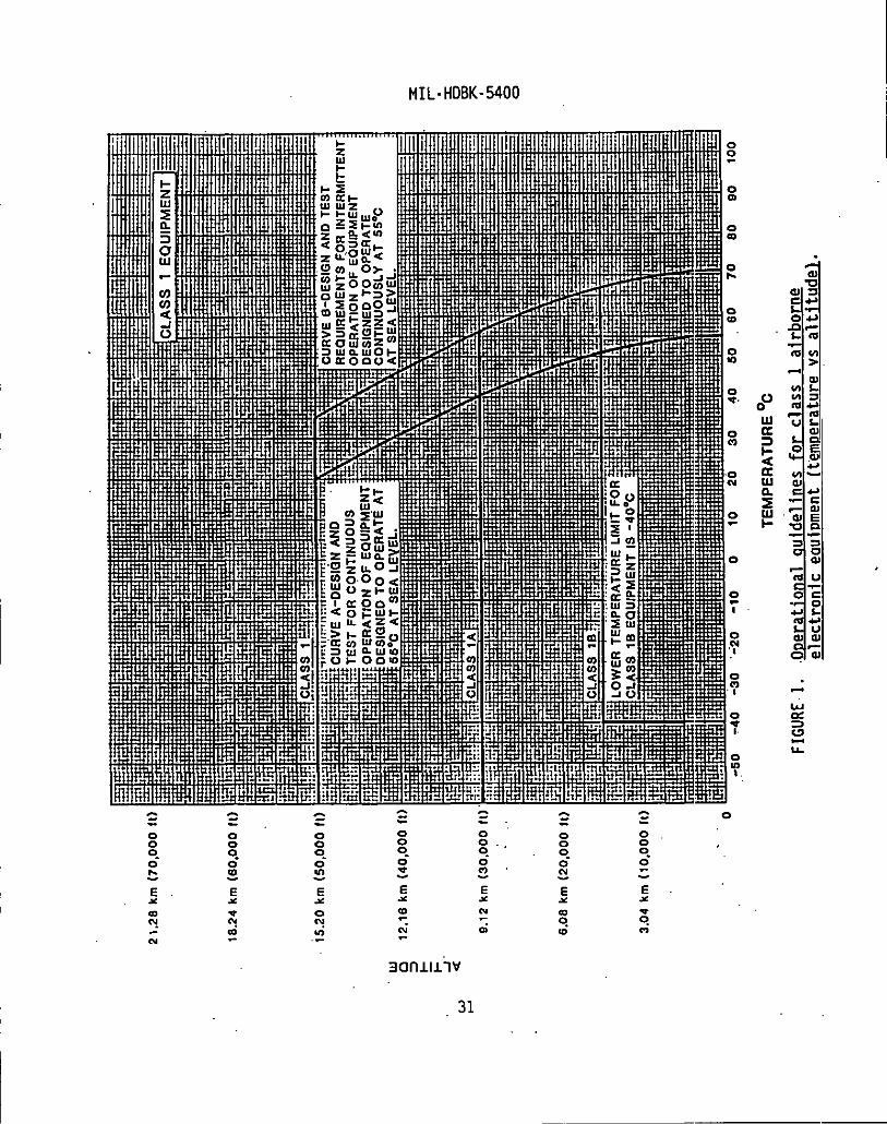
21.2
8km
(70,
00011
)
18.2
4km
(60,
000II
)
15.2
0km
(50,
000It
)
12.1
6km
(40,
000II
)
9.12
km(3
0,00
0II
).
.
6.08
km(2
0,00
0It
)
3.04
km(1
0,00
0II
)
o
TEMP
ERAT
URE
‘C
FIGU
RE-1
..O
oera
tion
algu
idel
ines
for
clas
s1ai
rbor
neel
ectr
onic
eaui
Dmen
t(t
empe
ratu
revs
alti
tude
l.
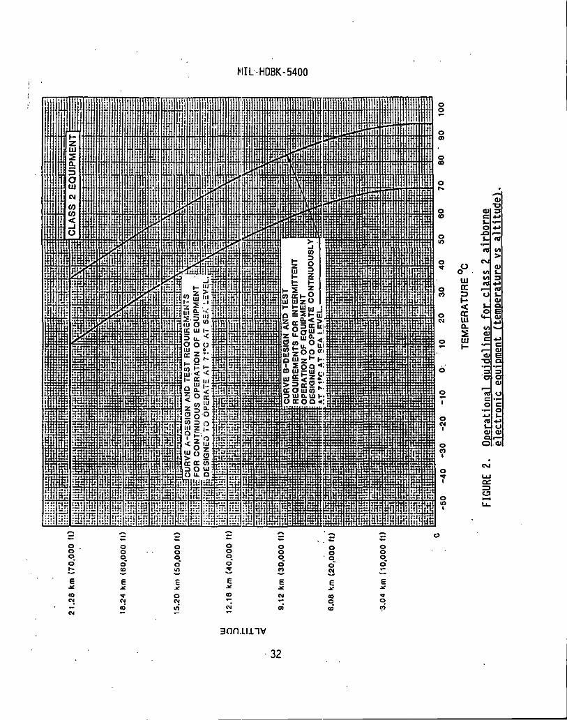
w N
21.2
8km
(70,
000f!
)
18.2
4km
(60,
00011)
15.2
0km
(50,
000It)
12.1
.3km
(40,
000I
t)
9.12
km(3
0,00
0It)
6.OB
km(2
0,00
0f;)
”
3.04
km(l
0,00
0fl) o
,.
TEMP
ERAT
URE
‘C
FIGU
RE2.
Oper
atio
nal
guid
elin
esfo
rcl
ass
2ai
rbor
neel
ectr
onic
eaui
Dmen
t(t
empe
ratu
revs
alti
tude
~.
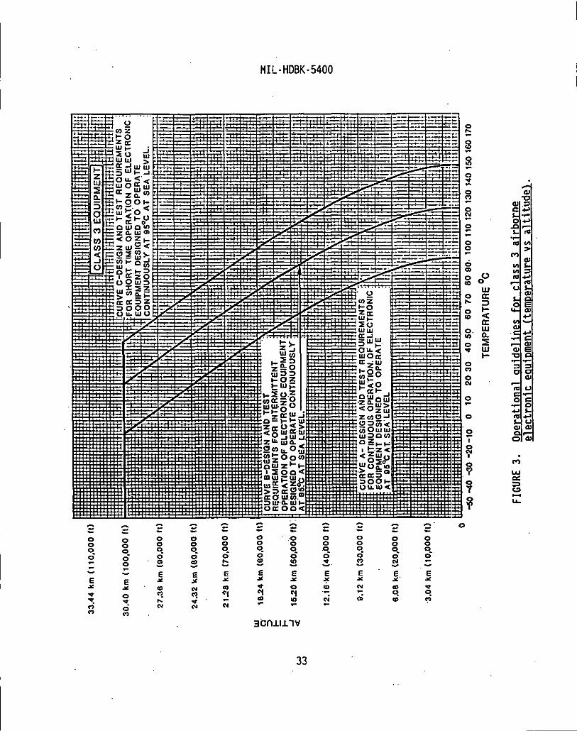
G.1
w
33.4
4km
(110,0
00II
)
30.4
0km
(100
,000
II)
27.3
Ekm
(oO,
OOOf
l)
24.3
2km
(80,
0001
t)
2,j~
km(7
0,00
0ft)
18.2
4km
(60,
000tl)
1520
km(S
0,00
0II)
12.i6k
m(4
0,00
0ft)
9.12
km(3
0,00
0It)
6.08
km(2
0,00
010
.3.0
4km‘(
10,O
OOII
)
. .—-5
040
-30-
20-1
0”0
1020
3040
5060
7080
90.
10011
0120
130
14O1
5O16
O17O
TEMP
ERAT
URE
‘C
FIGU
RE3.
Oper
atio
nal
guid
elin
esfo
rcl
ass
3ai
rbor
neel
ectr
onic
eaui
Dmen
t(t
empe
ratu
revs
alti
tude
~.

w *
33.4
4km
(ll0
,000
ft)
30.4
0km
(100
.000
(t)
27.3
6km
(90,
000f
l)
24.3
2km
(80,
0001
1),,
21.2
Bkm
(70.
000f
t)
1824
km(6
0,00
0fl)
lS20
km(5
0,00
0II)
12.1
6km(4
0,00
011)
9.12
km(3
0,00
011)
‘6.0
8km(2
0,00
0fl)
3.04
km(1
0,00
0ft) . “
3040
5060
7080
90’
10011
0120
I3O14
0150
1601
7018
019
020
0210
2202
3024
0250
2602
70
TEMP
ERAT
URE°
C
FIGU
RE4.
Oper
atio
nal
guid
elin
esfo
rcl
ass
4ai
rbor
neel
ectr
onic
eauiDm
ent
(tem
pera
ture
vsal
titu
del.
MIL-HDBK-5400
4.6.2.2 Altitude. The equipment should meet the.altitude conditions,for’”theapplicable class, listed in column VIII of table V,.both forcontinuous operation and exposure in a nonoperating condition. The altitudemay remain constant for long periods and vary at a rate as high as 0.5 inch ofmercury per second.
4.6.2.3 Jemoerature-al titude combination. The equipment should becapable of operating under the applicable temperature-altitude combinationsshown on figures 1 through 4, as applicable.
4.6.2.4 Jiumidity.. The equipment should withstand the effects ofhumidities up “to 100 percent, including conditions wherein condensation takesplace in and on the equipment. The equipment should withstand the aboveconditions during operating and nonoperating conditions. Fogging on theinside”of the cover glass of instruments should not occur.
4.6.2 .5,”Vibration.
4.6.2 .5.1 Eauioment nnrmallv mounted. When normally mounted (withvibration)isolators in pl’ace, if any), the equipment should not suffer damageor fail to meet specified performance when subjected to the applicable vibra-tion environment detailed herein’or. as specified in the detail specificationor contract. Selection of the applicable vibration environment (type ofexcitation, frequency range and energy density level as a “function of-aircraftand application’ location) should be determined using the following criteria.
4.6.2 .5.1.1 Eauioment desicined for installation in croDeller aircraft.Equipment of this type should withstand random excitation over the frequencYrange of 15 to 500 Hz with energy density levels specified by the appropriatefigure and table of MIL-STD-81O, Method 514.
..
4.6.2 .5.1.2 Eauioment desiwsed for installation in ,iet aircraft. Equip-ment of this type should withstand random excitation over the frequency rangeof 15 to 2000 Hz.with energy density levels specified by the appropriatefigure and table of MIL-STD-81O, Method 51A.
4.6.2 .5.’1.3 Eouioment desiwsed for installation in helicopters. Equip-ment of this type should withstand random excitation over the frequency rangeof 5 to 500 Hz with energy density levels specified by the appropriate figureand table of MIL-STD-81O, Method 514. ‘In addition, equipment of this typeshould withstand random excitation over the frequency range of 5 to 2000 HZfor,the purposes of environmental stress screening (ESS).
4.6.2 .5.1.4 flinimum intearitv test. Equipment normally mounted onisolators, but with isolators removed, should be capable of meeting specifiedperformance without suffering equipment damage, when subjected to a minimumintegrity test within the.vibration levels specified by the applicable figuresand tables of MIL-STD-81O, Method 514. The minimum integrity test should beapplied as a basic test for items which are not designed for any of the other
35

MIL-HDBK-5400
vibration environments cited above. The vibration levels and durations arenot based on application environments, but provide reasonable assurance thatthe equipment will withstand operations and handling during field installa-tion, removal, and repair. The test” exposures are based on “typical”electronic boxes and the maximum weight of the test item or subassembly shouldnot exceed approximately 36 kilograms (80 pounds).
4,.6.2.6 ~.
4.6.2.6.1 Eauibment. Equipment (with vibration isolators in place, ifany) should not suffer damage or subsequently fail to provide the performancespecified in the detail specification when subjected to 18 impact shocks of20g, consisting of 3 shocks in’opposite directions along each 3 mutuallyperpendicular axes, each shock impulse having a time duration of 6 to 9milliseconds. The “g” value should be within ~10 percent when measured with a0.2 to 250 Hz filter.
4.6,2 .6.2 Mountina base (crash safet~. With excursion stops or bumpersin place and with maximum rated load applied in a normal manner, the mountingbase, indiv~dual isolators; or other attaching devices should withstand atleast 12 impact shocks of 40g, consist ing,of 2 shocks in opposite directionsalong each of 3 mutually perpendicular axes. Each shock impulse should have”time duration of 6 to 9 milliseconds. The “g” value should be within *1Opercent when measured with a 0.2 to 250 Hz filter. Bending and distortionshould be permitted; however, there should be no failure to ‘the attachingjoints, and the equipment or dummy load should remain in place.
4.6.2 .6.3 Bench handlinq. The equipment should withstand the shockenvironment encountered during servicing.
4.6.2.7 Sand and dust. The equipment ”should withstand, in both anoperating and nonoperating condition, exposure to sand and dust particles asencountered in operational areas ofthe world.
4.6.2.8 w. The equipment should withstand, in both an operatingand nonoperating condition, exposure to fungus growth as encountered intropical climates. In no case should overall spraying’of the equipment benecessary to meet this requirement.
4.6.2.9 Salt atmosphere. The equipment should withstand, in both”anoperating and nonoperating condition, exposure to salt-sea atmosphere.
4.6.2.10 Exolosive conditions. The equipment should not cause ignitionof an ambient-explosive-gaseous mixture with air when operating in such anatmosphere.
36

I
I
I
MIL-HDBK-5400
5. DETAIL GUIDELINES
5.1. .Detailed mechanical and electrical desion. Specific requirementsfor individual equipment should be as specified in the detail specification orcontract. The detailed mechanical and electrical design of specific’equipmentshould be accomplished by the contractor, using the guidelines of thishandbook and any detail specification to which it is subsidiary. Thishandbook is detailed only to the extent considered necessary to obtain thedesired mechanical and electrical characteristics, performance and permanenceof the same. The design layout and assembly of the units and their componentoarts should be such as to facilitate auantit.v rmoduction and to result in.minimum size and weight.
5.2 Technical data. The requirements for the preparation and managementof technical data during the various equipment design, development andproduction phases should be selected and tailored from MIL-T-31000 andspecified in the contract. MIL-T-31oOO defi”nes the various types of drawings,associ’ated.lists and reports, along with the applicable Data Item Descriptions(DIDs) forli sting in the Contract Data Requirements List(CDRL, CID F~rm 1423).
5.3 llualit~ assurance.
5.3.1 Jtesoonsibilitv for tests and inspections. The contractor isresponsible for the performance of all tests and inspections as specifiedherein and in the detail specification or contract. -
5.3.2 Government verification. All quality and safety assurance opera-tions performed bythe contractor will be subject to Government verificationat any time. Verification ”consists of (a) surveillance of the operations todetermine that practices, methods, and procedures of the quality and safetyprogram requirements are being properly applied, (b) Government productinspection to measure quality and safety of product to be offered foracceptance, and (c),Government inspection of delivered items to assurecompliance with the detail specification or ,contract.
5.3.3 Failure criteria. Unless otherwise specified in the detailspecification or contract, the equipment, or portions thereof, should beconsidered to have failed the prescribed” tests and inspections when any of thefollowing conditions occur:
b.
c.
Equipment fails to meet the specified performance parameters, orwithin specified limits.
Structural failure or distortion.
Any condition that results in hazard to personnel or equipmentSafety.
37
I
1
I
I
I
d.
e.
f.
MIL-HDBK-5400
Process control deficiencies.
Inspection and test procedure deficiencies.
Improper labeling, handling and packaging.
5.3.4 Problem/failure renortinq a ond c rrectiveaction. Problem/failurereporting and corrective action of any failure occurring as a result of testsperformed during incoming inspection should be specified in the contract ordetail specification. In addition, a’report depicting the yield or percentageof failures that.occurrkd for each level of hardware should be specified inthe contract or detail specification. For correction and consideration, aGovernment-Industry Data Exchange Program (GIDEP) should be established andspecified in the contract or detail specification.
5:3.5 Desicm qualification tests. Design qualification testing shouldbe performed prior to commitment to production. The requirements for designqualification of the equipment, to demonstrate that. it conforms to specifiedperformance and reliability requirements under specified combinedenvironmenti$l conditions, should be cited in the contract or detailspecification. The requirements for environmental stress screening (ESS), todetect and correct latent manufacturing defects before the initiation ofreliability accounting tests and applied in conjunction with the designqualification requirements, “should be specified in the contract or detail“specification. These tasks identify the details to be specified by theacquisition activity and the applicable Data Item Description (DIDs) forincorporation into the CDRL (DD Form 1423). Refer to MIL-STD-2218 forguidance on thermal design verification tests.
5.3.6 First article t’ests. The first .art.icletests” should be performedin conjunction with production contracts only. The requirement for theperformance of first article tests should be specified in the detailspecification or contract. First article tests are those tests to be per-formed on one (1) or more equipments (as required by the detail specificationor contract) representative of production equipment to be supplied on contractor order.
5.3.6.1 Scooe of t@.” The requirement for first article tests shouldinclude all tests deem&1 necessary by the acquiring activity to determine thatthe equipment meets all of the ,requirernentsspecified in the detailspecification or contract. These tests should include environmental tests inaccordance with ”the test methods and procedures of MIL-STD-81O. Electro-magnetic interference tests and test methods should be in accordance withMIL-STD-461 . .
5.3.7 dua i~. The requirement for the performance ofquality conformance tests should be specified in the detail specification orcontract. Quality conformance tests are those tests deemed necessary to
~determine that the equipments submitted for acceptance under the contract are
38
MIL-HDBK-5400
I
I
I
I
equivalent in performance and construction to the approved first articleequipment. Quality conformance tests should consist of the following:
a. Individual tests to be performed on each equipment submitted foracceptance under the contract. These tests should includeenvironmental stress .screening (ESS) or burn- in..
b. Production reliability acceptance tests, to determine that productionequipment continues to conform to performance and reliabilityrequirements under specific environmental conditions, should bespecified in the contract or detail specification. Productionreliability acceptance tests identify those details to be specifiedby the acquisition activity, including test plan, sampling plan,environmental test conditions, performance requirements, and theapplicable Data Item Descriptions. (DIDs) for incorporation into theCDRL(DD Form 1423).
5:4 JsreDaration for delivery. Requirements for packaging, packing andmarking for shipment of equipment should be specified in the detailspecification or contract.
6. NDTES
(This section’ contains information of a general or exp~anatory nature whichmay be helpful, but is not mandatory. )
6.1 Intended use. This handbook is intended as a general design guidefor use in the development and preparation of detail specifications andcontracts for airborne electronic equipment to specify those requirementsapplicable to the specific equipment.
6.2 Details for inc~ion in eauigment specifications and contracts.Since this handbook only provides ”guidance; the detail specification (asprepared either by the Government, the”equipment manufacturer for theGovernment, or the prime vehicle contractor) or contract must specify actualrequirements from the multiple choices, tailoring, or exceptions available inthe following paragraphs:
a. Classification, reql[irements (see 1.2, 1.2.1).
b. Tailoring requirements (see 1.1.2 and Appendix B).
c. Warmup time. (see 4.2.8.1).
d. Electromagnetic interference characteristics (see 4.2.9).
e. Electrostatic discharge control program (see 4.2.10).
39

I
I
I
,
I
I
f.
9.
h.
,.1.
j.
k.
1.
ml.
n.
o.
P.
q.
r.
I s.
t.
1
‘ u.
v.
I w.
x.
Y.
z.
MIL-HDBK-5400
Human engineering requirements (see 4.2.14).
Maintainability program requirements (see 4.2.16).
Equipment orientation (see 4.2.22).
Pressure and altitude requirements for specifying air leakage (see4.2.24(g) and(h)).
Reliability program requirements (see 4.2.25).
Repairability requirements (see 4.2.26).
System safety program requirements (see 4.2.27.1).
Testability program requirements (see 4.2.29).
Thermal design requirements (see 4.2.30” and 4.2.30 ”.1).
Special tools (see’4.2.31.2).
Parts control program requirements and GFB (see 4.3.1 thru 4.3.3).
Samples for nonstandard parts and material approval, if required.
Nonstandard material approval (see 4.4.4.1).
Environmental test methods, procedures, limits, etc. (see 4.6 thru4.6.2.10). ~
Detail equipment design (see 5.1).
Technical data (see 5.2).
Equipment design qualification tests (see 5.3.5).
First article tests and sample (see 5.3.6, 5.3.6.1).
Accessory material and data to perform tests, if required.
Quality conformance requirements and tests (see 5.3.7).
Packaging requirements (see 5.4).
6.3 ~ elium. Helium should not be used as a pressurizing gasinsealed units containing electron tubes. When it is necessary to use heliumfor leak detection purpnses,’ exposure should be limited to. the time necessaryfor the test, followed by thorough purging.
40
I
MIL-HDBK-5400
6.4 Publications. In the design of electronic equipment, considerationshould be’given to the information contained in the following publication:
a.
6.5
Handbook, Preferred Circuits Navy Aeronautical ElectronicNAVAIR-16-1-519, Vnlume 2 Equipment.
Subject term (keyword) listing.
ClassificationDesign and constructionEnvironmental requirementsMaterial selectionMilitary standardParts selectionProcesses and finishes./Tailoring requirements,-
Custodians.:Army-CR -Navy-ASAir Force-l]
Reviewer activities:Army - MI, AR, AVh!avy ‘::,,.ECAir’’Force - 15, ”17, 9$DLA - ES
,., .. .. .. ... . .. . ...
.. ..,: ..,.,...
...
Preparing activity:Navy - AS
(Project GDRQ-0164)
. ...:
,“‘!.
...’
J “.,,.
41
,, ..- ,..

10.
THE
MIL-HDBK-5400
APPENOIX A
APPLICABLE OOCUMENTS
SCOPE
10.1 =. THIS APPENOIX IS NOT A MANOATORY PART OFINFORMATION CONTAINF.D }IEREIN IS INTENDED FOR GUIDANCE.
THIS HANDBOOK.
10.2 This ”appendix lists specifications, standards, handbooks and otherpublications selected for their applicability in the design and constructionof airborne electronic equipment.”” Those parts and materials covered bydocuments listed in this appendix will be considered standard items. Whenpart selection standards are referenced, the documents listed in the selectionstandard have the same status as those listed directly in this appendix andthe parts they cover are also considered standard (unless otherwise restrictedor banned for airborne applications).
10.3 selection of d~!!mnts for nonstandard parts and materials. WhenAppendix A does not provide a document suitable for the design requirement,selection of specifications and standards for nonstandard parts and materialsshould be specified hy the contracting or design activity, unless otherwisecited herein or in the referenced MIL-I{OBK-454 guidelines.
20. APPLICABLE DOCUMENTS
20.1 The documents listed in this appendix are applicable to the extentspecified directly herein or in the referenced MIL-HDBK-454 guidelines.
20.2 ~gplicable is~e. Unless otherwise specified, the issues of thesedocuments are those listed in the issue of the Department of Defense Index ofSpecifications and Standards (DODISS) and supplement thereto, cited in the.solicitation. Later revisinns, amendments and documents superseding thoselisted in Appendix A may be used when preferred by the contractor. When alater issue is used, all applicable requirements of the later revision should
I be used.
20.3 CoDies. Unless otherwise indicated, copies of federal and militaryspecifications, standards and handhnoks are available from the StandardizationOocurnent Order Desk, 700 Robbins Avenue, Building 40, Philadelphia, PA 19111-5094. Addresses for ordering copies of non-government documents are listed onthe fol~owing page.
A-1
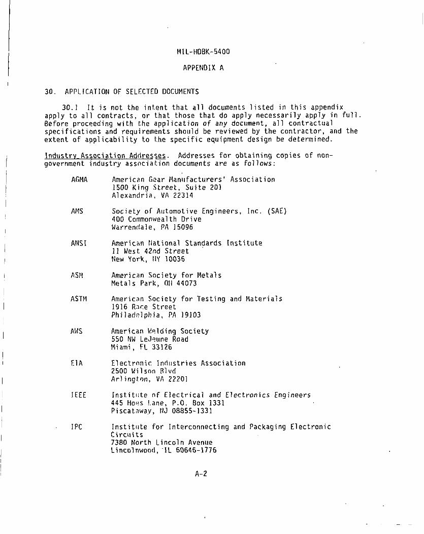
MIL-HDBK-5400
APPENDIX A
30. APPLICATION OF SELECTED DOCUMENTS
30.1 It is not the intent that all documents listed in this appendixapply to all contracts, or that those that do apply necessarily .apply in full.Before proceeding with !he application of any document, all contractualspecifications and requirements should be reviewed by the contractor, and theextent of applicability to the specific equipment design be determined.
Industry Association Addresses. Addresses for obtaining copies of non-government industry assnciat.inn documents are as follows:
AGMA
AMS
ANSI
PSN
ASTM
AKS
EIA
IEEE
IPC
American Gear Manufacturers’ Association1500 King Street, Suite 201Alexandria, VA 22314
Society of Automotive Engineers, Inc. (SAE)400 Commonwealth OriveWarren(fale, PA 15096
American National Standards Institute11 West 42nd StreetNew York, lIY10036
American Society for MetalsMetals Park, 0}144073
American Society for Testing and Materials1916 R~ce StreetPhiladelphia, PA 19103
American t!elding Society550 NW LeJ?une RoadMiami, FL 33126
Electronic Indllstries2500 Wilsnn BlvrlArlington, VA 22201
Association
Institliteof Electrical and Electronics Engineers445 Hoes !.ane,P.O. Box 1331Piscatawa,y, NJ 08855-1331
Institllte for Interconnecting and Packaging ElectronicCircuits7380 North Lincoln AvenueLincolnwond, “IL 60646-1776
A-2

MIL-HDBK-5400
APPENDIX A
NAS National Standards Association1200 QliinceOrchard BoulevardGaithersburg, MD 20878
NFPA National Fire Protection AssociatingBattery March ParkQuincy, MA 02269
UL Underwriters Laboratories,333 Pfingsten RoadNorthbrook, IL 60062-2096
FEDERAL SPECIFICATIONS
A-A-52401
A-A-52414
A-A-55485
L-P-516
V-T-285
V-T-295
FF-B-171
FF-8-187
FF-B-575
FF-N-836
FF-R-556
FF-S-85
FF-S-B6
FF-S-92
Inc
Bearing, Sleeve (Steel-Backed)
Bearing, Roller, Thrust
Pads, Electrical-Electronic Component, GeneralReq,lirements for
Pla:;tic.Sheet”and Plastic Rod, Thermosetting, Cast
Thread, Polyester
Thread, Nylnn
Ilea,-ings,8all, Annular (General Purpose)
Bearing, Roller, Tapered
Bolts, Hexaqon and Square
Nut, Square, Hexagon, Cap, Slotted, .Castle Knurled,Welding and Single Ball Seat
Riv?t, Solid, Small; Rivet, Split, Small; Rivet Tubular,Sma’ll;Flat Washer (Burr); and Cap, Rivet, GeneralPurpnse
Scrw, Cap,
Screw, Cap,
Slotted and Hexagon-Head
Socket-Head
Screw, Machine; Slotted, Cross Recessed or Hexagon Head
A-3
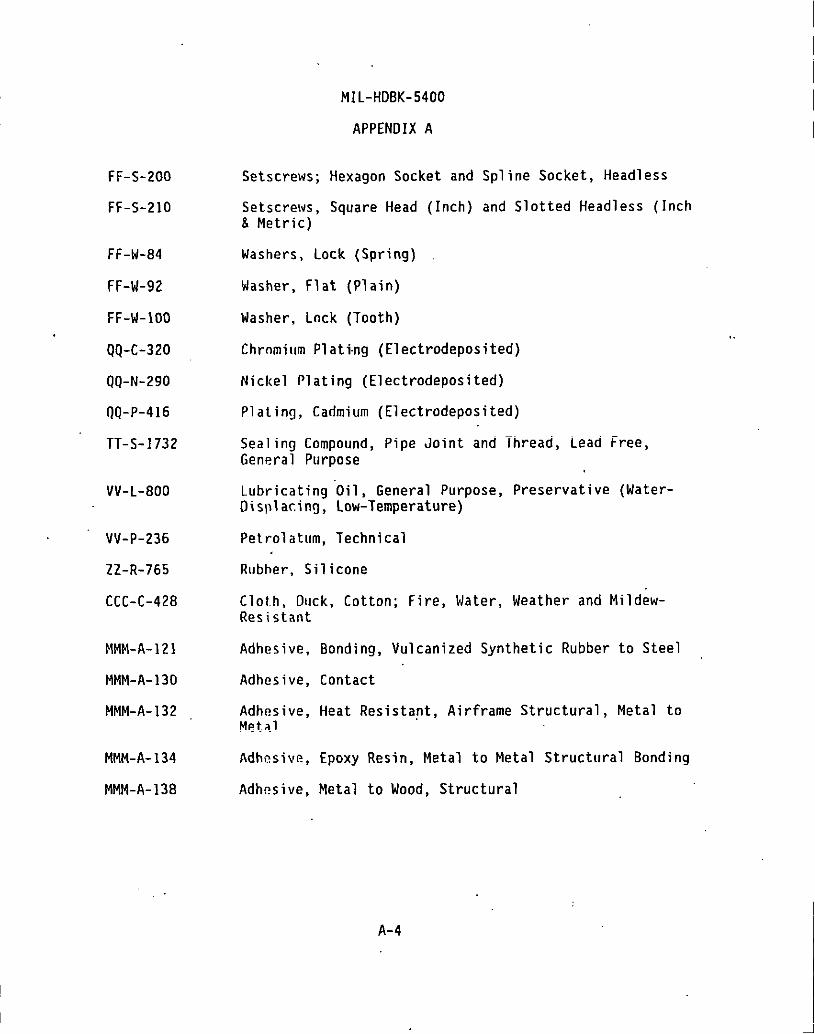
FF-S-200
FF-S-21O
FF-W-84
FF-W-92
FF-W-1OO
QQ-C-320
QQ-N-290
QQ-P-416
TT-S-1732
VV-L-800
VV-P-236
72-R-765
CCC-C-428
MMM-A-121
MMM-A- 130
MMM-A-132
MMM-A- 134
MMM-A-138
MIL-HDBK-5400
APPENDIX A
Setscrews; Hexagon Socket and Spline Socket, Headless
Setscrews, Square Head& Metric)
Washers, Lock (Spring)
Washer, Flat (Plain)
Washer, Lock (Tooth)
Inch) and Slotted Headless
Chromium Plating (Electrodeposited)
Nickel Plating (Electrodeposited)
Plating, Cadmium (Electrodeposited)
Sealing Compound, Pipe Joint and Thread,General PurDose
ead Free,
Inch
Lubricatina”Oil. General PurDose, Preservative (Water-Oisplacingl Low~Temperature)
Petrol atum, Technical
Rubher, Silicone
Clolh, Duck, Cotton; Fire, Water, Weather and Mildew-Resistant
Adhesive, Bonding, Vulcanized Synthetic Rubber to Steel
Adhesive, Contact
Adhesive, Heat Resistant, Airframe Structura”Metal
Adhesive, Epoxy
Adhesive, Metal
, Metal to
Resin, Metal to Metal Structural 8onding
to Wood, Structural
A-4

MMM-A-181 Adhesive,
MMM-A,-189 Adhesive,Purpose
MMM-A-1617 Adhesive,
MMM-A-1931 Adhesive,
—
MIL-HDBK-5400”
APPENDIX A
Phenol, Resorcinol, or Melamine Base
Synthetic-Rubber, Thermoplastic, General
Rubber Base, General Purpose
Epoxy, Silver Filled, Conductive
MILITARY SPECIFICATIONS
MIL-I-1O
MIL-M-i4
MIL-C-17
MIL-S-61
MIL-T-152
MIL-C-172
MIL-V-173
MIL-W-530
MIL-C-572
MI.L-I-631
MIL-J-641
MIL-P-642
MIL-T-713
Insulating Compound, Electrical, Ceramic, Class L
Molding Compounds, Thermosetting
Cable, Radio Frequency, Flexible and Semirigid, GeneralSpecification for
Shunts, Instrument, External, 50 Millivolt (LightweightType )
Treatment, Moisture and Fungus Resistant, ofCommunications, Electronic and Associated ElectricalEquipment ‘
Cases, Bases, Mounting and Mounts, Vibration (For UseWith Electronic Equipment in Aircraft)
Varnish, Moisture and Fungus Resistant (For TreatmentCommunications, Electronic and Associated Equipment)
Webbing, Textile, Cotton, General Purpose, Natural orColm-s
of
in
Cords, Yarns and Monofilament, Organic Synthetic Fiber
[nsulation, Electrical, Synthetic-Resin Composition,Nonrigid
Jack, Telephone, General Specification for
Plug, Telephone and Accessory Screws, GeneralSpecification for
Twine, Fibrous: Impregnated, Lacing and Tying
A-5

MIL-S-1222
MIL-I-1361
M1L-L-2105
MIL-L-3150
I MIL-I-3158
i
MIL-I-3190
I MIL-T-3530
NIL-L-3661
MIL-I-3825
I MIL-L-3890
MIL-L-3918
MIL-A-3920
MIL-B-39!I0
MIL-W-4088
MIL-S-5002
MIL-I.-5O57
MIL-8-5087
MIL-W-5088
MIL-HOBK-5400
APPENDIX A
Studs, Bolts, Hex Cap Screws,Nuts
Socket Head Cap Screws and
Instrument Auxiliaries. Electrical Measurinq: Shunts,Resistnrs and Transformers
Lubricating Oil, Gear, Multi-Purpose (Metric)
Lubricating Oil, Preservative, Medium
Insulation Tape, Electrical Glass-Fiber (Resin Fi”and Cord, Fibrous-Glass
Insulation Sleeving, Electrical, Flexible, Coated,General Specification for
led);
Thread and Twine, Mildew Resistant or Water RepellantTreated
Lampholders, Indicator Lights, Indicator-Light Housings,and Indicator-Light Lenses, General Specification for
Insulation Tape, Electrical, Self-Fusing:” For Use inElectronics, Communications and Allied Equipment
Lines, Radio Frequency Transmission (Coaxial, AirDieleci ric)
Lubrictlting Oil, Instrument, Jewel Bearing
Adhesive, Optical, Thermosetting
Bearings, Roller, Needle, Airframe, Anti- Friction, Inch
Webbings, Textile, Woven Nylon
Surface Treatments and Inorganic Coatings for MetalSurfaces of Weapons Systems
Lights, Instrument, Individual, General Specification for
Bondinn, Electrical and Lightning Protection, forAerospace Systems
Wiring, Aerospace Vehicle
A-6

MIL-H-5440
MIL-A-5540
MIL-C-5541
MIL-F-5591
MIL-R-5674
MIL-B-5687
MIL-L-6085
MIL-I.-6O86
M[L-I.-6363
MIL-C-6781
MIL-FI-6812
MIL-W-6858
MIL-1-7444
MIL-S-7742
MIL-P-7788
MIL-M-7793
MIL-8-7838
MIL-HD8K-5400
APPENDIX A
Hydraulic Systems, Aircraft, Design and Insta’Requirements for
Adh?sive, Polychloroprene
ation
Chemical Conversion Coatings on Aluminum and AluminumAllnys
Fasteners, Panel; Nonstructural
Rivets, Structural, Aluminum Alloy, Titanium ColumbiumAlloy, General Specification for
8earings, Sleeve, Washers, Thrust, Sintered, Metal PowderOil Impregnated, General Specification for
Lubricating Oil, Instrument, Aircraft, Law Volatility
Luhricat.ing Oil, Gear, Petroleum Base
Lamps, Incandescent, Aircraft Service, GeneralSpecification for
Control Panel, Aircraft Equipment, Rack or ConsoleMounted
Bolts, Aircraft
Weldinq, Resistance, Spot and Seam
Insulat.inn Sleeving, Electrical, Flexible
Screw Threads, Standard, Optimum Selected Series; GeneralSpecification for
Panels, Information, Integrally Illuminated
Meter, Time Total izing
Bolt, Internal Wrenching, 160 KS I FTU
A-7
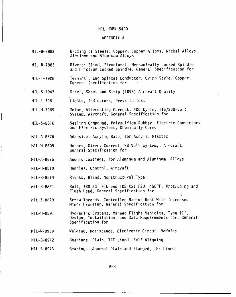
NIL-B-7883
MIL-R-7885
MIL-T-7928
MIL-S-7947
MIL-L-7961
MIL-M-7969
MIL-S-B516
MIL-A-8576
MIL-M-8609
MIL-A-8625
MIL-H-881O
MIL-R-8814
MIL-8-f3831
MJL-S-8879
M[L-11-8891
MIL-W-8939
MIL-B-8942
MII.-II-8943
MIL-HDBK-5400
APPENDIX A
8razing of Steels, Copper, Copper Alloy s,’Nickel Alloys,Aluminl!m and Aluminum Alloys
Rivets; Blind, Structural, Mechanically Locked Spindleand Friction Locked Spindle, General Specification for
Terminal, Lug Splices Conductor, Crimp Sty”Genera”l Specification for
Steel, Sheet and Strip (1095) Aircraft Qua”
“Lig!]ts,Indicators, Press to Test
~, Copper,
ity
Motnr, Alternating Current, 400 Cycle, 115/200-VoltSystem, Aircraft, General Specification for
Sealing Cnmpound, Polysul fide Rubber, Electric Connectorsand Electric Systems, Chemically Cured
Adh(!sive, Acrylic 8ase, for Acrylic Plastic
Motnrs, Direct Current, 28 Volt System, Aircraft,General Specification for
Ano[lic Coatings, for Aluminum and Aluminum Alloys’
Handles, Control, Aircraft
Riv,?ts,Blind, Nonstructural Type
Bolt, 180 KSI FTU and 108 KS I FSU, 450°F, Protruding andFlush Ilead, General Specification for
Screw “ihreads, Controlled Radius Root With IncreasedMinor [Iiameter, General specification for
Hydra~llic Systems, Manned Flight Vehicles, Type III,Design, Installation, and Data Requirements for, GeneralSpecification for
Welding, Resistance, Electronic Circuit Modules
t$earlngs, t’laln,
8earings, Journa’
--- . .TFE Lined, Self-Aligning
Plain and Flanged, TFE Lined
A-8
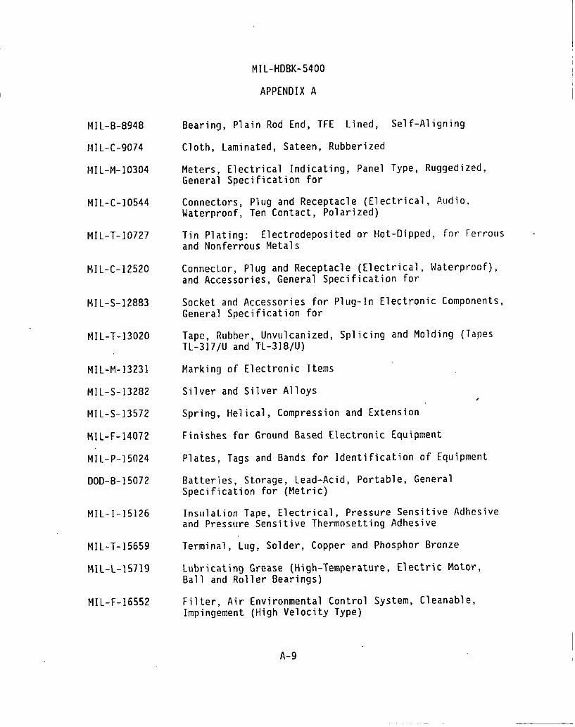
MIL-B-8948
HIL-C-9074
MIL-M-103O4
MIL-C-10544
MIL-T-10727
MIL-C-12520
MIL-S-12883
MIL-T-13020
MIL-M-13231
MIL-S-13282
MIL-S-13572
MIL-F-14072
MIL-P-15024
DOD-B-15072
MIL-I-15126
MIL-T-15659
MIL-L-15719
MIL-F-16552
MIL-HDBK-5400
APPENDIX A
Bearing, Plain Rod End, TFE Lined, Self-Aligning
Cloth, Laminated, Sateen, Rubberized
Meters, Electrical Indicating, Panel Type, Rugged ized,General Specification for
Connectors, Plug and Receptacle (Electrical, Audio,Waterproof, Ten Contact, Polarized)
Tin Plating: Electredeposited or Hot-Dipped, for Ferrousand Nonferrous Metals
Connector, Plug and Receptacle (Electrical, Waterproof),and Accessories, General Specification for
Socket and Accessories fnr Plug-In Electronic Components,General Specification for
Tape, Rubber, Unvulcanized, Splicing and Molding (TapesTL-317/U and TL-318/U)
Marking of Electronic Items
Silver and Silver A11OYS,
Spring, Helical, Compression and Extension
Finishes for Ground 8ased Electronic Equipment
Plates, Tags and Bands for Identification of Equipment
Batteries, Storage, Lead-Acid, Portable, GeneralSpecification for (Metric)
Insulation Tape, Electrical, Pressure Sensitive Adhesiveand Pressure Sensitive Thermnsetting Adhesive
Terminal , Lug, Solder, Copper and Phosphor Bronze
Lubricating Grease (High-Temperature, Electric Motor,8all and Rnller Bearings)
Filter, AirImpingement
Environmental Control System, Cleanable,(High Velocity Type)
A-9
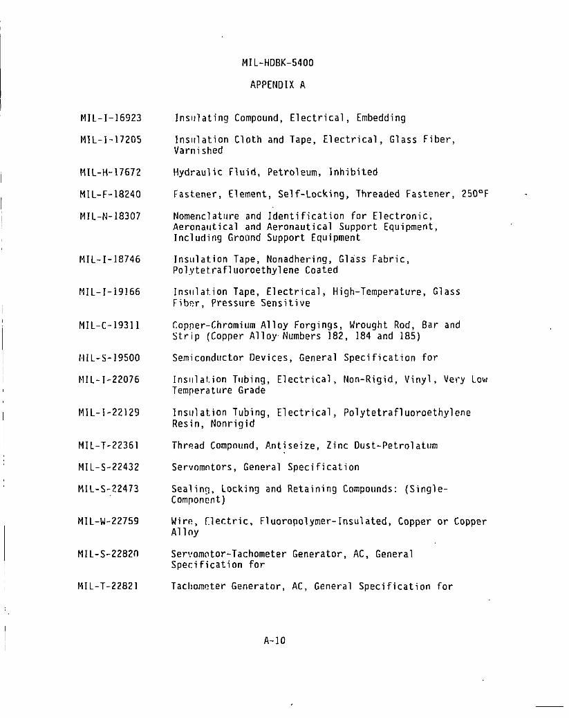
MIL-HDBK-5400
APPENDIX A
MIL-I-16!323
MIL-1-17205
MIL-H-17672
MIL-F-18240
MIL-N-18307
MIL-I-18746
NIL-I-19166
MIL-C-19311
IIIL-S-19500
MIL-I-22076
MIL-I-22129
NIL-T-22361
MIL-S-22432
MIL-S-22473
MIL-w-22759
MIL-S-22820
Insulating Compound, Electrical, Embedding
insulation Cloth and Tape, Electrical, Glass Fiber,Varnished
Hydraulic Fluid, Petroleum, Inhibited
Fastener, Element, Self-Locking, Threaded Fastener, 250°F -
Nomenclature and Identification for Electronic,Aeronautical and Aeronautical Support Equipment,Including Grotlnd Support Equipment
Inslllat.ion Tape, Nonadhering, Glass Fabric,Pol~~tet.rafluoroethylene Coated
Inslllat.ion Tape, Electrical, High-Temperature, GlassFibw, Pressure Sensitive
Copper-Chromium Alloy Forgings, Wrought Rod, Bar andStrip (Copper AlloyNumbers 182, 184 and lB5)
Semiconductor Devices, General Specification for
Ins,llat.ion Tubing, Electrical, Non-Rigid, Vinyl, Very LowTemperature Grade
Ins.ulat.ionTubing, Electrical, Polytetrafl uoroethyleneResin, Nonrigid
Thread Compnund, ).ntiseize, Zinc Oust- Petrolatum
Servomntors, General Specification
Sealing, Locking and Retaining Compounds: (Single-Component)
Wire, Electric, Fluoropolymer- Insulated, Copper or CopperAl1ny
Servomotor-Tachometer Generator, AC, GeneralSpecification for
MIL-T-22821 Tachometer Generator, AC, General Specification for
A-10
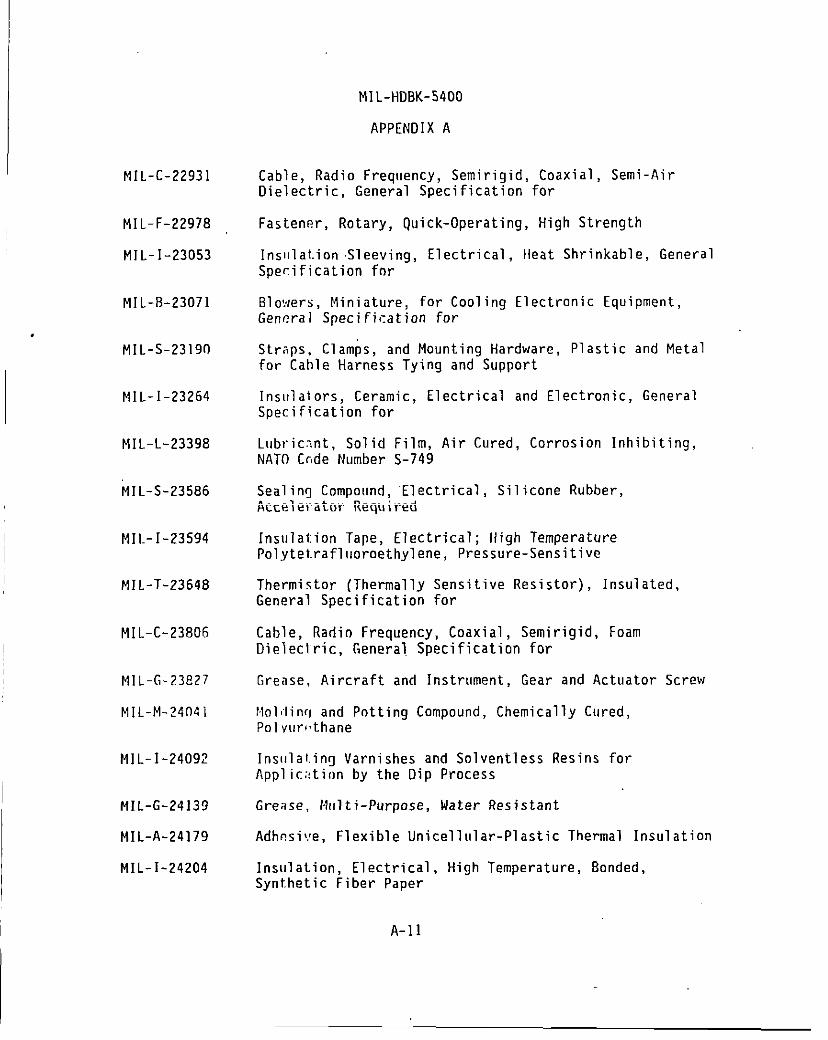
MIL-C-22931
MIL-F-22978
MIL-I-23053
MIL-B-23071
MIL-S-23190
MIL-I-23264
MIL-L-23398
MIL-S-23586
MII.-I-23594
MIL-T-23648
MIL-C-23806
MIL-G-23827
MIL-M-2’404i
MIL-I-24092
MIL-G-24139
MIL-A-24179
MIL-I-24204
MIL-HD8K-5400
APPENDIX A
Cable, Radio Frequency, Semirigid, Coaxial, Semi-AirDielectric, General Specification for
Fastener, Rotary, Quick-Operating, High Strength
Inslilat.ion Sleeving, Electrical, Heat Shrinkable, GeneralSpecification fnr
Blo,:/ers,Miniature, for Cooling Electronic Equipment,General Specification for
Straps, Clamps, and Mounting Hardware, Plastic and Metalfor Cable Harness Tying and Support
Insulators, Ceramic, Electrical and Electronic, GeneralSpecification for
lubric~nt. Solid Film, Air Cured, Corrosion Inhibiting,NATO Cc,deNumber S-749
Sealing Compound, “Electrical, Silicone Rubber,Accelerator Required
Insulation Tape, Electrical; High TemperaturePol.ytet.rafluoroethylene, Pressure-Sensitive
Thermistor (Thermally Sensitive Resistor), Insulated,General Specification for
Cable, Radio Frequency, Coaxial, Semirigid, FoamDielectric, General. Specification for
Grease, Aircraft and Instrument, Gear and Actuator Screw
hlolilinfland Pntting Compound, Chemically Cured,Polvur!,thane
Insulal.ing Varnishes and Solventless Resins forApplic::tion by the Dip Process
Grease, H{{lti-Purpose, Water Resistant
Adhesive, Flexible Unicellular-Plastic Thermal Insulation
Insulation, Electrical,Synthetic Fiber Paper
A-n
High Temperature, 8onded,
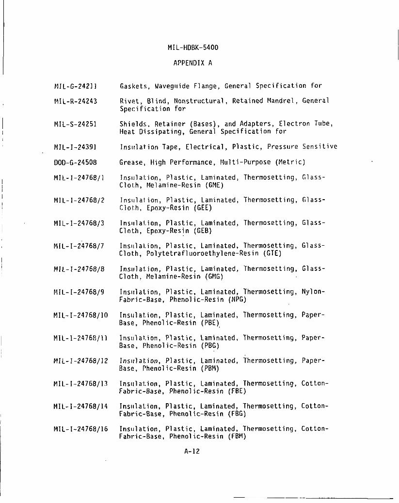
I
MIL-G-24211
MIL-R-24243
MIL-S-.2425I
MIL-I-24391
DOO-G-24508
MIL-I-24768/l
MIL-1-24768/2
MIL-I-24768/3
MIL-I-24768/7
MIL-I-24768/8
MIL-I-24768/9
MIL-I-24768/10
MIL-1-2476 t3/11
MIL-
MIL-
MIL-
-24768/12
-24768/13
-24768114
MIL-I-24768/16
MIL-HD8K-5400
APPENOIX A
Gaskets, Waveg{lide Flange, General Specification for
Rivet, Blind, Nonstructural, Retained Mandrel, GeneralSpecification for
Shields, Retainer (Bases), and Adapters, Electron Tube,Heat Dissipating, General Specification for
Insl!lation Tape, Electrical, Plastic, Pressure Sensitive
Grease, High Performance, Multi-Purpose (Metric)
lnslllation, Plastic, Laminated, Thermosetting, Glass-Cloth, Melamine-Resin (GME)
lns!]lalien, Plastic, Laminated, Thermosetting, Glass-Clol,h, Epoxy-Resin (GEE)
Inslllal.ion, Plastic, Laminated, Thermosetting, Glass-Cloth, Epoxy-Resin (GE8)
Insl[lation, Plastic, Laminated, Thermose.tting, Glass-Clot.h, Polytetrafl uoroethylene-Resin (GTE)
Insulation. Plastic, Laminated, Thermosetting, Glass-Clot.h,Melamine-Resin (GMG)
Inslllation, Plastic, Laminated, Thermosetting, Nylon-Fabric-8ase, Phenol ic-Resin (NPG)
Insulation, Plastic,8ase, Phenol ic-Resin
Insulation, Plastic,Base, Phenol ic-Resin
Insulation. Plastic,Base, Phenol ic-Resin
Laminated, Thermosetting, Paper-(PBE),
Laminated, Thermosetting, Paper-(PBG)
Laminated, Thermosetting, Paper-(PBM)
Insl!lation, Plastic, Laminated, Thermosetting, Cotton-Fabric-8ase, Phenol ic-Resin (FBE)
Inslllation, Plastic, Laminated, Thermosetting, Cotton-Fabric-Base, Phenol ic-Resin (FBG)
Insulation, Plastic, Laminated, Thermosetting, Cotton-Fabric-8ase, Phenol ic-Resin (FBM)
A-12

MIL-I-24768/17
MIL-N-25027
MIL-K-25049
MIL-A-25463
MIL-L-25467
MIL-P-25518
MIL-L-27160
MIL-W-27265
MIL-R-27384
MIL-C-27S30
MIL-D-28728
MIL-M-28787
MIL-O-28803
MIL-P-29590
MIL-T-31000
MIL-M-3851O
MIL-HD8K-5400
APPENOIX A
Insulation, Plastic, Laminated, Thermosettin~Cloth, Silicone-Resin (GSG)
Nut, Self-Locking, 250°F, 450°F and 800”F
Knobs, Control, Electronic Equipment, Genera’Specification for
. Glass-
Adhesive, Film Form, Metallic Structural SandwichConstrl[ction
Lighting, Integral, Aircraft Instrument, GeneralSpecification for
Plastic Material, Silicone Resin, Glass Fiber Base, Low-Pressure Laminated
Lighting, Instrument, Integral, White, GeneralSpecification for
Webbinq, Textile; Woven Nylon, Impregnated
Rivet, Blind, Drive Type
Cable, Power, Electrical and Cable Special Purpose,Shielded and Unshielded, Electrical, GeneralSpecification for
Oial, Control, Multi-Turn Counters, General Specificationfor
Modules, Standard’ Electronic, General Specification for
Oisplay Optoelectric, Readouts, 81acklighted Segmented,General Specification for
Power Supplies, Airborne, Electronic, GeneralSpecification for
Technical Oata Packages, General Specification for
Microcircuits, General Specification for (Inactive)
A-13
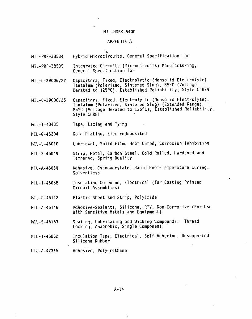
MIL-HDBK-5400
APPENDIX A
MIL-PRF-38534
MIL-PRF-38535
MIL-C-39006/22
MIL-C-39006/25
MIL-T-43435
MIL-G-45204
MIL-L-4601O
MIL-S-46049
MIL-A-46050
MIL-1-46058
MIL-P-46112
MIL-A-46146
MIL-S-46163
MIL-1-46852
IIIL-A-47315
Hybrid Microcircuits, General Specification for
Integrated Circuits (Microcircuits) Manufacturing,General Specification for
Capacitors, Fixed, Electrolytic (Nonsolid Electrolyte)Tantalum (Polarized, Sintered Slug), 85°C (VoltageElerateclto 125°C), Established Reliability, Style CLR79
Capacitors, Fixed, Electrolytic (Nonsolid Electrolyte),Tant.al(tm (Polarized, Sintered Slug) (Extended Range),85°C (Vnltage Derated to 125°C), Established Reliability,Style CLR81
Tape, Lacing and Tying
Gold Plating, Electrodeposited
Lubricant, Solid Film, Heat Cured, Corrosion Inhibiting
Strip, Metal, Carbon”Steel, Cold Rolled, Hardened andTempered, Spring Quality
Adhesive, Cyanoacrylate, Rapid Room-Temperature Curing,Solvent.less
lnsllla~.ing Compound, Electrical (for Coating PrintedCircuit Assemblies)
Plastic Sheet and Strip, Polyimide
Adhesive-Sealants, Siiicone, RTV, Non-Corrosive (For UseWith Sensitive Metals and Equipment)
Sealing, Lubricating and Wicking Compounds: ThreadLocking, Anaerobic, Single Component
Insulation Tape, Electrical, Self-Adhering, UnsupportedSilicone Rubber
Adhesive, Polyurethane
A-14

MJL-HDBK-5400
APPENDIX A
HIL-A-47318
MIL-A-4B611
MIL-B-49030
MIL-B-494311
MIL-B-49436
MIL-I-49456
MIL-B-49458
MIL-R-50781
MIL-A-52194
MIL-S-55041
MIL-C-55116
MIL-B-55130
HIL-T-55156
MIL-T-55164
MIL-C-55181
I MIL-O-5531O
MIL-A-55339
MIL-T-55631
MIL-C-81021
Adhesive, Copolymer Polyurethane
Adhesive System, Epoxy-Elastomeric, for Glass-To-Metal
8atteries, Dry (Alkaline)
Batteries, Non-Rechargeable, Lithium Sulfur ~i~xicle
Batteries, Rechargeable, Nickel-Cadmium, Sealed
Inslllat.ion Sheet, Electrical, Silicone Rubber, ThermallyConduce.ive, Fiberglass Reinforced
8att.cries, Non-Rechargeable, Lithium Manganese Oioxide
Resolvor, Electrical, Linear, General Specification for
Adhesi’!e, Epoxy (for Bonding Glass Reinforced Polyester)
Switches, Waveguicje, General Specification for
Conneci.ors, Miniature, Audio, Five-Pin and Six-Pin,Genera”l Specification for
Batteries, Rechargeable, Nickel-Cadmium, Sealed
Terminals, Lug, Splices, Conductor; Screw Type, GeneralSpecification for
Terminal Boards, Molded, Barrier, Screw and,Stud Types,and Associated Accessories, General Specification for
Connectors, Plug and Receptacle, Intermediate Power(Electrical, Waterproof) Type MM, General Specificationfor
Oscillator, Crystal Controlled, General Specification for
Adapters, Connector, Coaxial, Radio Frequency (BetweenSeries and Within Series), General Specification for
Transformers, Intermediate Frequency, Radio Frequencyand Discriminator, General Specification for
Copper-Beryllium Alloy (Copper Alloy Numbers C17500 andC1751O), Strip
A-15
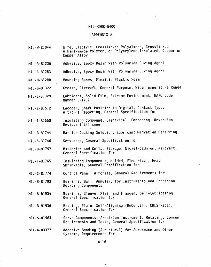
MIL-W-81044
MIL-A-81236
MIL-A-81253
MIL-M-81288
MIL-G-81322
MIL-L-81329
NIL-E-81512
MIL-1-81550
MIL-8-81744
MIL-S-81746
MIL-B-81757
MIL-I-81765
MIL-C-81774
MIL-8-81793
MIL-B-B1934
MIL-8-81936
MIL-S-81963
MIL-A-83377
MIL-HD8K-5400
APPENDIX A
Wire, Electric, Crosslinked Polyalkene, Cross linkedAlkane-imide Polymer, or Polyarylene Insulated, Copper orCopper Alloy
Adhesive, EPOXY Resin With Polyamide Curin9 A9ent
Adhesive, Epoxy Resin With Polyamine Curing Agent
Mollnting Bases, Flexible Plastic Foam
Grease, Aircraft, General Purpose, Wide Temperature Range
Lubricant, Solid Film, Extreme Environment, NATO CodeNumber S-1737
Encoder, Shaft Position to Oigital, Contact Type,Altitude Reporting, General Specification for
Insulating Compound, Electrical, Embedding, ReversionResistant Silicone
8arrier Coating Solution, Lubricant Migration Deterring
Servtorqs, General Specification for
8atteries and Cells, Storage, Nickel-Cadmium, Aircraft,General Specification for
Insulating Components, Molded, Electrical, HeatShrinkable, General Specification for
Control Panel, Aircraft, General Requirements for
8earings, Ball, Annular, for Instruments and PrecisionRotating Components
Bearinqs, Sleeve, Plain and Flanged, SeGeneral Specification for
Bearing, Plain, Self-Aligning (8eCu 8alGeneral Specification for
Servo Components. Precision Instrument.
f-Lubricating,
CRES ‘Race),
Rotatinq, CommonRequirements and” Tests, General Specification f;r
Adhesive Bonding (Structural) for Aerospace and OtherSystems, Requirements for
A-16
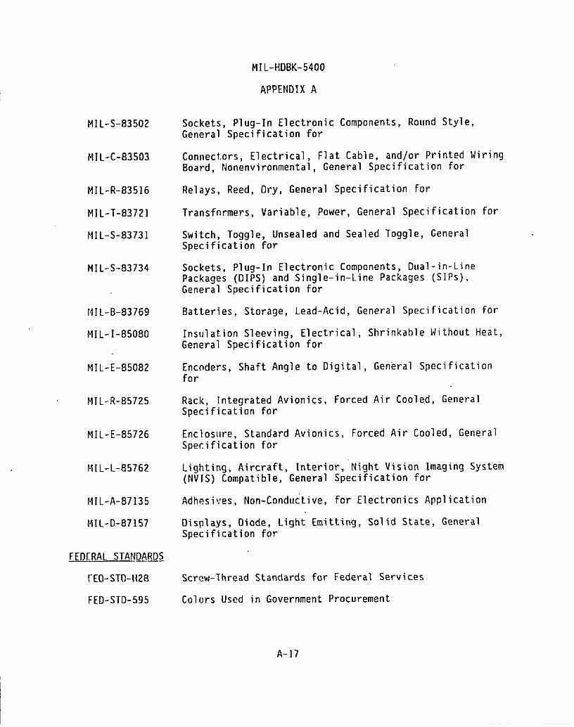
I
MIL-S-83502
MIL-C-83503
MIL-R-83516
MIL-T-83721
MIL-S-83731
MIL-S-83734
NIL-8-83769
MIL-I-85080
MIL-E-85082
MIL-R-85725
MIL-E-85726
NIL-L-85762
MIL-A-87135
MIL-O-87157
FEDERAL STAN~m
~EO-STO-H28
FED-STD-595
MIL-HD8K-5400
APPENDIX A
Sockets, Plug-In Electronic Components, Round Style,General Specification for
Connectors, Electrical, Flat Cable, and/or Printed Wiring8oard, Nonenvironmental, General Specification for
Relays, Reed, Dry, General Specification for
Transfnrmers, Variable, Power, General Specification for
Switch, Toggle, Unsealed and Sealed Toggle, GeneralSpecification for
Sockets, Plug-In Electronic Components, Dual-in-LinePackages (DIPS) and Single-in-Line Packages (SIPS),General Specification for
8atteries, Storage, Lead-Acid, General Specification for
Insulation Sleeving, Electrical, Shrinkable Mithout Heat,General Specification for
Encoders, Shaft Angle to Digital, General Specificationfor
Rack, Integrated Avionics, Forced Air Cooled, GeneralSpecification for
Enclosure, Standard Avionics, Forced Air Cooled, GeneralSpecification for
Lighting, Aircraft, Interior, Night Vision Imaging System(NVIS) Compatible, General Specification for
Adhesi!?es, Non-Conductive, for Electronics Application
Displays, Diode, LightSpecification for
Screw-Thread Standards
Emitting, Solid State, General
for Federal Services
Colors Used in Government Procurement
A-17

MIL-HDBK-5400
APPENOIX A
MILITARY STANDARDS
MIL-STD-12
MIL-STII-22
MIL-STO-108
MIL-STCI-130
MIL-STD-195
MIL-STD-196
MIL-STD-198
MIL-STD-199
MIL-STD-200
M[L-STD-202
MIL-STC&248
MII.-STD-276
MIL-sTo-280
MIL-STD-411
MIL-STD-470
MI1,-STD-471
MIL-STI-)-681
MIL-STD-683
Abbreviations for Use on Drawings, Specifications,Standards and in Technical Documents
Welded Joint Oesign
Definitions of and Basic Requirements for Enclosures forElectric and Electronic Equipment
Identification Marking of U.S. Military Property
Marking of Connections for Electrical Assemblies
Joint [electronics Type Designation
Capacitors, Selection and Use of
Resistc,rs, Selection and Use of
Electrnn Tubes, Selection of
System
Test Methods for Electronic and Electrical ComponentParts
Welding and Brazing Procedure and PerformanceQualification
Impregnation of Porous Metal Castings and Powdered MetalComponents
Definitions of Item Levels, Item Exchangeability, Models,and Related Terms
Air,crew Station Altering Systems
Maintainability Program for Systems and Equipment
Maintainability Verificati on/Demonstration/Evaluation
Identification Coding and Application of Hook-Up and LeadWire
Crystal Units (Quartz) and Crystal Holders (Enclosures)and Oscillators, Selection of
iA-18

MIL-HDBK-5400
I
I
I
I
I
I
MIL-STD-701
MIL-STD-704
MIL-STD-71O
MIL-STD-783
MIL-STD-81O
MIL-STD-838
MIL-STD-083
MIL-ST~-889
MIL-STD-965
MIL-STD-983
MIL-sTf)-1130
MIL. STD-1132
MIL-STD- 1189
MIL-STD-1277
MIL-STD-1279
MIL-STD-1285
MIL-STO-1286
MIL-STD- 1327
MIL-STD-1328
MIL-STD-1329
APPENDIX A
Lists of Standard Semiconductor Devices
Aircraft EJectric Power Characteristics
Synchros, 60 and 400 Hz, Selection and Application of
Legends for Use in Aircrew Stations and on AirborneEquipment
Environmental Test Methods and Engineering C.’ :
Luhric?tinn ‘of Military Equipment
Test.I,lsthodsand Procedures for Microelectronics
Dissimilar Metals
Parts Control Program*
Substi!.ution List fnr Microcircuits
Connections, Electrical, Solderless, Wrapped
Switches and Associated Hardware, Selection and Use of
Standard department of Defense Bar Code Symbology
Splices, Chips, Terminals, Terminal 8oards, BindingPosts, Electrical
Meters, Electrical. Indicating, Select inn and Use of
Marking nf Electrical and Electronic Parts
Transfnrmers, Inductors, and Coils, Selection and Use of
Fl:nges, Coaxial and Waveguide; and Coupling Assemblies,Selection of
Coljplers, Directional, Selection of
Switches, RF Coaxial, Selection of
* fiIL-STD-965 is planned for retention and willstanilardpractice or an acquisition guidelineJanuary 1996.
A-19
be redefined as either aA final decision is due by

MI L-STD-1334
MI L-sTD-134fi
MI L-STD-1352
MI L-STD-1353
MI L-STD-1358
MI L-STD-1360
MI L-STD-1378
MI L-STI)-1389
MI L-STD-1390
MI L-.STO-1395
MI L-’sTD-l399
MI L-STD-1472
MI L-STD-1498
MI L-STD-1516
MI L-STD-1553
MI L-STD-1562
MI L-STD-1595
MI L- STD-1629
MI L-STD-1636
MI L-STD-1637
Process for
MI L-HDBK-5400
APPENDIX A
Barrier Coating of Anti-Friction Bearings
Relays, Select inn and Application of
Att.enu?.tors, Fixed and Variable, Selection of
Electrical Connectors, Plug-In Sockets and AssociatedHardware, Selection and Use of
Waveguides, Rectangular, Ridge and Circular, Selection of
Fuses, Fuseholders and Associated Hardware, Selection andUse of
Reqllircments for Employing Standard Electronic Modules
Design Requirements for Standard Electronic .Modules
Level of Repair Analysis (LORA)
Filters and Networks, Selection and Use of
Inl:erfnceStandard for Shipboard Systems, Section 300Electric Power, Alternating Current (Metric)
Human Engineering Design Criteria for Military Systems,Equipment and Facilities
Circuit. Breakers, Selection and Use of
Unified Cnde for Coatings and Finishes of DOO Equipment
Digital Time Division Command/Response Multiplex OataBuss
Lists of Standard Microcircuits
Qualification of Aircraft, Missile and Aerospace FusionWelders
Procedllresfor Performing a Failure Mode, Effects andCriticality Analysis
Adapters, Coaxial to Waveguide, Selection of
Dummy Loads, Electrical, Waveguide, Coaxial, andStripline, Selection of
A-20

MIL-STD-1638
MIL-STD-1639
MIL-STD-1640
MIL-STD-1646
MIL-STD-1788
MIL-STD-1812
MIL-STD-1861
DDD-STD-1866
MIL-STD-2038
MIL-STD-2113
MIL-STD-2120
MIL-STD-2162
MIL-STD-2175
MIL-STD-2200
MII.-STD-22I8
MIL-STD-2219
MS27212
MS33522
MIL-HDBK:5400
APPENOIX A
Waveguide Assemblies, Rigid and Flexible. Selection of
Power Dividers. Power Combiners. and Power Divider/Combiners, Selection of
Mixer Stages, Radio Frequency, Selecticr ::
Servicing Tools for Electric Contacts and “.:--=-Selection and Use of
Avionics Interface Design Standard
Type Designation, Assignment and Method for Dbta
ions,
rling
Electrical and Electronic Assemblies, 8oards, Cards’andAssociated Hardware, Selection and Use of
Soldering Process, General (Non-Electrical) (Metric)
Requirements for Employing Standard Power S{lpplies
Radin Frequency Circulators and Isolators, Selection of
Cnnnect.nrs, Electromagnetic Interference (EMI) FilterContact
Amplifiers, Radio Frequency and Microwave, Solid State,Selection of
Castings, Classification and Inspection of
Reqllir?ments for Employing Standard Enclosure Systems
Thermal Oesign, Analysis, and Test Procedures forAirhor:le Electronic Equipment
Fusion Welding for Aerospace Applications
Terminal Board Assembly, Molded-In Stud, Electric
Rivets, 81ind, Structural, Mechanically Locked andFriction Retainer Spindle (Reliability andMaintainability), Design and Construction Requirementsfor
A-21
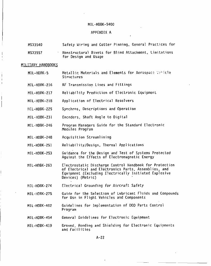
NIL-HDBK-5400
APPENDIK A
MS33540
14S33557
MILITARY HANW
MIL-HD13K-5
MIL-HDIIK-216
MIL-HD13K-217
MIL-HOBK-218
MIL-HDBK-225
MIL-HDBK-231
MIL-HDBK-246
MIL-HDBK-248
MIL-HDBK-251
MIL-}{DBK-253
MIL-HllBK-263
HIL-HOBK-274
MI L-H13RK-275
MI L-HDBK-402
MI L-HDBK-454
I NIL-HDBK-419
Safety Wiring and Cotter Pinning, General Practices for
Nonstructural Rivetsfor Design and Usage
for Blind Attachment, Limitations
Metallic Materials and Elements for Aerospac: ‘::’icleStrllctut-es
RF Transmission Lines and Fittings
Reliability Prediction of Electronic Equipment
Application of Electrical Resolvers
Synchrns, Descriptions and Operation
Encnders, Shaft Angle to Oigital
Program Managers Guide for the Standard ElectronicModlJles Program
Acqllisition Streamlining
Reliability/Design, Thermal Applications
Guidance for the Design and Test of Systems ProtectedAgainst, the Effects of Electromagnetic Energy
Electrostatic Discharge Control Handbook for Protectionof Electrical and Electronics Parts, Assemblies, andEquipment (Excluding Electrically Initiated ExplosiveDevices) (Metric)
Electrical Grounding for Aircraft Safety
Guide for the Selection of Lubricant Fluids and Compoundsfor Use in Flight Vehicles and Components
Guidelines for Implementation of DOD Parts ControlProgram
General Guidelines for Electronic Equipment
Grnund, Rnnding and Shielding for Electronic Equipmentsand Facilities
A-22

MI L-HDFIK-472
MI L-HDBK-660
MI L-HDBK-691
MI L-HDBK-730
MI L-HDBK-1553
MI L-HIIBK-ZOOO
NIL-BUL-103
MIL-HOBK-5400
APPENOIX A
Maintainability Prediction
Fabrication of Rigid Waveguide Assemblies (Sweep Bendsand Twists)
Adhesive Bonding
Materials Joining
Multiplex Application Handbook
Soldering of Electrical and Electronic Assemblies
List.of Standardized Military Drawings (SMDS)
OTHER G!N/ERNMENT 00CUMEf~
NAVAIR-16-I-519, Handbonk, Preferred Circuits Navy Aeronauticalvol. 2 Electronic Equipment
10 CFR 20 Code of Federal
21 CFR 1000-1050 Code of FederalParts 1000-1050
29 CFR 1910 Code of Federal1910
Regulations, Title 10, Chapter 1, Part ?-0
Regulations, Title 21, Chapter I,
Regulations, Title 29, Chapter XVII, Part
VHSIC Interoperability Standards. Includes specifications for the TM-bus,ETM bus, Pi bus, and VHSIC Electrical Specification. (Copies availablefrom Naval Research Laboratory, Code 5305, Washington, DC 20375 -5000.)
Tester Independent Support Software System (TISSS) Specifications ‘(Copiesavailable from TISSS Prngram Office, RAOC/RBR, Griffiss Air Force Base, NY13441-5700)
NON-GOVERNMENT DOCUMEM
SAE AMS 363BE Plastic Tubing, Electrical Insulation, IrradiatedPolyolefin, Pigmented, Semi-Rigid, Heat-Shrinkable 2to 1 Shrink Ratio
SAE AMS 36530 Tubing, Electrical Insulation, Standard Wall, ExtrudedPolytetrafl uoroethylene .(PTFE)
SAE AMS 36546 Tubing, Electrical Insulation, Light Wall, ExtrudedPolytetrafl uoroethylene (PTFE)
A-23

I
I
SAE AMS 3655A
ASTM A29fA29M
ASTM A228/A228M
ASTM A313
ASTM A588fA558M
ASTM A682
ASTM’A684/A684M
ASTM Bi34
ASTM B159
ASTM B194
ASTM B196/B196M
, ASTM B197/B197M
ASTM B206
ASTM B522
ASTM B633
ASTM D495
ASTM D635
ASTM DIOOO
MIL-HDBK-5400
APPENDIX A
Tubing, Electrical Insulation, Thin Wall, ExtrudedPolytetrafl uoroethylene (PTFE)
Steel Bars, Carbon and Alloy, Hot Wrought and ColdFinished, General Requirements for
Steel Wire, Music Spring Quality
Chromium-Nickel Stainless and Heat Resisting Steel SpringWire
Steel, Structural, High-Strength Low Alloy Structural,with 50 KSI (345 MPA), Minimum Yield Point to 4 In. (100MM) Thick
Steel, Strip, High Carbon, Cold RolGeneral Requirements for
Steel, Strip, High CarbonSpecification for
Wire, 13rass
Wire, Phosphor Wire (Metr
Cold Rol
c)
Cormer-Beryllium A11oY Plate, Sheet,
ed, Spring Quality,
ed, Standard
Strip, and RolledBar” -
Copper-Beryllium Alloy Rod and Bar
Copper-Beryllium Alloy Wire
Copper-Nickel-Zinc Alloy (Nickel Silver) Wire and CopperNickel Alloy Wire (Metric)
Gold-Silver-Platinum Electrical Contact Alloy
Electrodeposited Coatings of Zinc on Iron and Steel
Insulation, Solid Electrical, High Voltage, Low Current,Dry Arc Resistance of
Plastics, Self-Supporting, in a Horizontal Position, Rateof Burning and/or Extent of Time of, Burning of
Pressure-Sensitive Adhesive Coated Tapes Used forElectrical Insulation, Methods of Testing
A-24
I

ASTM D3295
ASTM D4956
ASTM F872
ANsI/l Pc-D322
ANSI C95.1
ANSI C95.2
ANSI N2.1
EIA RS-310-C
IEEE 200
IEEE 1076
NAS498
NAS547
NAS1686
NAS1687
NFPA 70
UL 94
MIL-HDBK-5400
APPENOIX A
PTFE Tubing, Specification for
Sheeting, Retroreflective, For Traffic Control
Filter Unit, Air Conditioning, Viscous Impingement Type,Cleanable
Guidelines for Selecting Printed Wiring Board Sizes UsingStandard Panel Sizes
Safety Levels With Respect to Human Exposure to RadioFrequency Electromagnetic Fields, 300 KHz to 100 GHz
Radio Frequency Radiation Hazard Warning Symbol
Radiation Symbol
Cabinets, Racks, Panels and Associated Equipment
Electrical and Electronic Parts and Equipments, ReferenceDesignations for
Manllal, VHDL Language Reference
8olts, Shear, 95 KSU FSU
Fastener, Rotary, Quick-Operating, “High Strength
Rivet, Blind, Aluminum Sleeve, Mechanically Locked,Spindle, Bulbed
Rivet, Blind, Monel and Inconel Sleeve, MechanicallyLocked Spindle, Bulbed
National Electrical Code
Tests for Flammability of Plastic Materials for Parts inDevices and Appliances
Netals Handbook (Vol I) (ASM)
American Gear Manufacturers Association (AGMA)
A-25

I
i
10.
THE
MIL-HDBK-5400
APPENDIX B
SAMPLE TAILORING GUIOE
SCOPE
10.1 m. THIS APPENOIX IS NOT A MANOATORY PART OF THIS HANOBOOK.INFORMATION CONTAINED HEREIN IS INTENDEO FOR GUIOANCE.
10.2 This appendix provides a sample tailoring guide for MIL-HDBK-5400based on the relationship of tailoring specific guidelines during variousdevelopment and production phases as defined in MIL-HOBK-248. This guide isnot intended to be restrictive as to the methods/factors to be considered fortailoring applications. Examples of other methods/factors concerned withtailoring of MIL-HOBK-5400 requirements are shown in paragraph 40.
ZO. APPLICABLE 00 CEMENTS (Reference OnlY)
MIL-HDBK-248 Acquisition Streamlining
30. APPLICATION OF SAMPLE TAILORING GUIOE
30.1 The sample tailoring guide contained herein cross-referencesindications of.tailoring applicability for MIL-H08K-5400 requirements tovarious phases of item development and production as defined in MIL-HOBK-248.Codes and abbreviations used in the sample tailoring guide table are asfollows:
Tailoring Requirements
N- Not applicable this phaseA- Applicable this phaseT- Essentially a “tailoring” paragraphG- General statement - tailoring not required
Program Phases
CON- Conceptual (Research)D&V- Oemonstration & ValidationFSEO- Fu”llScale Engineering DevelopmentPROO- Production
30.2 Guide for the extent of tailoring to be effected during programphases.
Conceptual (Research) - Specifications and standards requirements shouldbe tailored and limited to minimum technical design objectives and broadbasic performance and functional requirements. Application of “costdriver” requirements should be very limited.
8-1
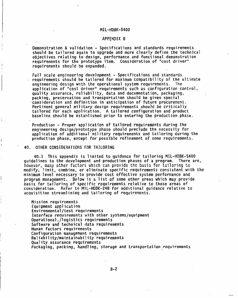
MIL-HDBK-5400
APPENDIX B
Demonstration & validation - Specifications and standards requirementsshould be tailored again to upgrade and more clearly define the technicalobjectives relating to design, performance and functional demonstrationrequirements for the prototype item. Consideration of “cost driver”requirements should be expanded.
Full scale engineering development - Specifications and standardsrequirements should be tailored for maximum compatibility of the ultimateengineering design with the operational system requirements. Theapplication of “cost driver” requirements such as configuration control,quality assurance, reliability, data and documentation, packaging,packing, preservation and transportation ‘should be given specialconsideration and definition in anticipation of future procurement.Pertinent general military design requirements should be criticallytailored for each application. A tailored configuration and productbaseline should be established prior to entering the production phase.
Production - Proper application of tailored requirements during theengineering design/protntype phase should preclude the necessity forapplication of additional military requirements and tailoring during theproduction phase, except for possible refinement of some requirements.
40. OTHER CONSIDERATIONS FOR TAILOi ING
40.1 This appendix is limited to guidance for tailoring MIL-HDBK-5400guidelines to the development and production phases of a program. There are,however, many other factors which can provide the basis for tailoring tomodify, limit, combine, or eliminate specific requirements consistent with theminimum level necessary to provide cost effective system performance andprogram management. Below is a list of some other areas which may providebasis for tailoring of specific requirements relative to those areas ofconsideration. Refer to MIL-HDBK-24B for additional guidance relative toacquisition streamlining and tailoring of requirements.
Mission requirementsEquipment applicationEnvironmental/test requirementsInterface requirements with other systems/equipmentOperational./logistics refauirementsSoftware and”technical data requirementsHuman factors requirementsConfiguration management requirementsReliabil ity/maintai nability requirementsQuality assurance requirementsPackaging, packing, handling, storage and transportation requirements
B-2

PARAGRAPH
4.1.14.1.2
4.1.3
.::; .1TABLE I
MIL-HDBK-5400
APPENDIX B
DESCRIPTION CON D&V FSED PROD
Tailoring of MIL-HDBK-454 guidelinesStandard hardware acquisition and
reliability program (SHARP)Requirements, tables and figures13esign and constructionUntitledGeneral desiqn and construction
4.2.2 Access ibilit~4.2.34.2.44.2.54.2.64.2.74.2.7.14.2.7.24.2.84.2.8.14.2.8.24.2.94.2.104.2.114.2.11.14.2.11.24.2.124.2.134.2.144.2.154.2.15.14.2.164.2.174.2.17.14.2.17.24.2.17.34.2.184.2.194.2.20.4.2.2f4.2.224.2.234.2.23.14.2.23.24.2.23.3
Ant i-jamming-Castings, metalCorona and electrical breakdown preventionDeratingElectrical overload protectionResettable circuit protectorsSpare fusesElectrical powerWarm-up timeUntitledElectromagnetic interference controlElectrostatic discharge controlEnclosuresStandardized avionics enclosuresOther enclosuresFabricationGrounding, bonding and shieldingHuman engineeringInterchangeabilityInterchangeability of reordered equiPmentMaintainahilityMarki nqLahels -Wire codinq for identificationOperational program markingMicrophonicsMoisture pocketsMultiplexingNomenclature assignmentOrientationPanelsControl panelsElectroluminescent panelsRanges of ad.illstahleparts
G
!GG
NNNANNNNNNNNANNN
:NNNNN
INGNNNNNNNN
G
AGGG
AANA
:AAAAAAAAAAAAANNAANNNGNANAAAAA
G
AGGG
1?AAAAAAAA
;AAAAAAA
:“AAAA4AGAAAA
:AA
B-3

MIL-HDBK-5400
APPENDIX B
PARAGRAPH
4.2.244.2.254.2.264.2.274.2.27.14.2.27.24.2.284.2.28.14.2.28.24.2.28.34.2.294.2.304.2.30.14.2.314.2.31.14.2.31.24.2.31.34.2.324.2.334.34.3.14.3.1.14.3.24.3.34.3.44.3.4.14.3.4.2
4.3.4.34.3.4 .3.14.3.4.44.3.4.5TABLE 114.3.54.3.64.3.74.3.84.3.8.14.3.8.24.3.94.3.9.14.3.9.24.3.9.3
OESCRIPTION
PressurizationReliabilityRepairabilitySafetySystem safetyPersonnel SafetyTest provisionBuilt-in test devicesExternal test pointsFailure effectTestability programThermal designCooling design dataTool SSetscrew wrenchesSpecial toolFurnishing and stowingStandardized power suppliesWorkmanshipParts select innGovernment.-furnished baseline (GFB)Choice of partsNonstandard partsParts control programApproval of partsContracts under category IContracts for equipment which fall under
categories 11 and IIIReordered production equipmentContinuation of production .Replacing of approved partsEquipment performanceParts selectionSubstitution of partsBatteriesBearingsCapacitorsFixed, tantalilrnelectrolyticAluminum electrolyticCircuit breakersManual operationPosition identificationOrientation
CON O&V FSED PROD
NN
:GANNNNN
[NNN
:NNNNNN
;
T
!NG
N
1NNNNNNN
NNN
:ANNNNNNNNNNNNNAA
;AAT
T
;AG
AANAAAAAAN
AAA
;AAAAAAAAAAAA
:AAAAAAT
T
:AG
AAAAAA
:AA
B-4
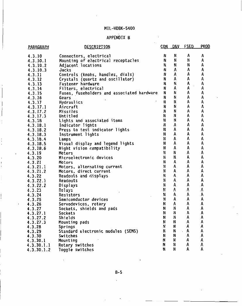
(
I
I
PARAGRAPH
4.3.104.3.10.14.3.10.24.3.10.34.3.114.3.124.3.134.3.144.3.154.3.164.3.174.3.17.14.3.17.24.3.17.34.3.184.3.18.14.3.18.24.3.18.34.3.18.44.3.18.54.3.18.64.3.194.3.204.3.214.3.21.14.3.21.24.3.224.3.22.14.3.22.24.3.234.3.244.3.254.3.264.3.214.3.27.14.3.27.24.3.27.34.3.284.3.294.3.304.3.30.14.3.30 .1.14.3.30.1.2
MIL-HD8K-5400
APPENOIX 8
DESCR 1PTION CON D&V FSED PROO
Connectors, electrical NMounting of electrical receptacles NAdjacent locations NJacksControls (knobs, handles, dials) 1Crystals (quartz and oscillator) NFastener hardware NFilters, electrical NFuses, ,fuseholders and associated hardware NGearsHydraulics )AircraftMissiles 1Untitled NLights and associated items NIndicator lights NPress to test indicator lights NInstrument liqhts NLampsVisual displa,y and legend lightsNight vision compatibilityMetersMicroelectronic devicesMotorsMotors, alternating currentMotors, direct currentReadouts and displaysReadoutsOisplaysRelaysResistorsSemiconductor devicesServodevices, rotarySockets, shields and padsSocketsShieldsMountinq Dads
NN
1NNN
INNNNNNNNNN
Springs-Standard electronic modules (SEMS) :SwitchesMounting :Rotary switches NToggle switches N
8-5
A
[
:AAAAAAAAA
:AAAA
:AAAAAAAAA
;AAAAAAAAAA

MIL-HDBK-5400
APPENDIX 8
PARAGRAPH
4.3.314.3.31.14.3.31.24.3.31.34.3.324.3.334.3.344.3.354.3.35.14.3.35.24.3.35.34.3.35.44.3.35.54.3.35.64.44.4.14.4.24.4.34.4.44.4.4.1TABLE 1114.4.54.4.64.4.74.4.84.4.94.4.104.4.114.4.124.4.13
4.4.144.4.154.5TABLE IV4.5.14.5.1.14.5.1.24.5.1 .2.14.5.1 .2.24.5.1 .2.34.5.24.5.34.5.44.5.4.1”
QLs-
TerminationsNumber of wires per terminal or lugNumber of lugs per terminalNumber of wires in a connector contactTransformers, inductors and coilsTubes, electronWaveguides and related itemsWire and cableWire and cable, internalWiring practices, internalWire and cable, external interconnectionExternal wiring practicesCable, coaxial (RF)Printed wiringMaterial selectionChoice of materialsPolyvinyl chloride (PVC) materialsStandard materialsNonstandard materialsApproval of nonstandard materialsMaterials selectionAdhesivesArc-resistant materialsConformal coatingDissimilar metalsEncapsulation and embedment materialsFibrous material, organicFlammability of materialsFungus-inert materialsInsiilators, insulating and dielectric
materialsLubricantsMetals, cnrrosion-resi stantProcesses and finishesProcesses and finishesProtective platings and coatingMaterialsAluminum alloySurface, generalSurfaces, bonded and groundedSurfaces, extreme wear-resistantMagnesium and magnesium alloysZinc and zinc-plated partsFinishesCases and front panels
CON O&V FSED PROD
NNN
;NNN
IINGNNNN
INN
NAN
;N
1
NNNG
GGG
:
:GNN
NNN
:ANNN
1GNNNA
:AA
NANNNNNA
ANNG
GGGGGG
:NN
AAA
:AAAAAAGAA
:
:AA
A
1’A
:
;
AAAG
GGG
;GGGAA
B-6

PARAGRAPH
4.5.4.24.5.4.34.64.6.14.6.1.14.6.24.6.2.14.6.2 .1.1TABLE V4.6.2 .1.24.6.2.24.6.2.34.6.2.44.6.2.54.6.2 .5.14.6.2 .5.1.1
4.6.2 .5.1.2
4.6.2 .5.1.3
4.6.2 .5.1.44.6.2.64.6.2 .6.14.6.2.6 24.6.2.6 34.6.2.74.6.2.84.6.2.9
I 4.6.2.10
Fasteners
MIL-HDBK-5400
APPENDIX B
DESCRIPTION
and assembly screwsOther standard finishesEnvironmental service guidelinesMIL-STD-BIO environmental tests ,UntitledEquipment operational requirementsTemperatureOperatingEnvironmental conditionsNonoperatingAltitudeTemperature-altitude combinationHumidityVibrationEquipment normally mountedEquipment designed for installation in
propeller aircraftEquipment designed for installation in
jet aircraftEquipment designed for installation in
helicoptersMinimum integrity testShockEquipmentNounting base (crash safety)Bench handlingSand and dustFungusSalt.atmosphereExplosive conditions
,,
CON O&V FSEO PROD
A
;TTA
:
AAAAAA
A
A
AAAAA
t
:A
B-7

MIL-HDBK-5400
I
INDEX
flescription
Access ibility ......................................Accessory ..........................................Acquisition activity ...............................Adhesives ..........................................Adjacent location s.................................Airborne ...........................................Aircraft ...........................................Altitude ...........................................Aluminum alloy .....................................Aluminum electrolyte c ..............................Anti -jamming .......................................APPLICABLE DOCUMENTS ...............................Applicable issues ..................................Application ........................................Approval of nonstandard materials..................Approval nf parts ................................Arc-resistant material s........ ....................
Batteries ..................... ........1............Bearing s...........................................Bench handling .....................................Built- in test devices ..............................
Cable, coaxial (RF),..............................Capacitors .........................................Cases and front panels.............................Casting s, metal ....................................Choice of material s................................Choice ofpart,s ....................................Circuit breakers ...................................Classification .....................................Complete operating equipment .......................Conformal coating ...................................Connectors, electrical .............................Continuation of product ion..... .................Contracts for equipment which fall under Categor
11 and I I I . . . . . . . . . . . . . . . . . . . . . . . . . . . . . . . . . ...Contracts under Category I . . . . . . . . . . . . . . . . . . . . . .Control panel s..................................Controls (knobs, handles, dials) ................
. .es.......
Cooling design data ..............................Copies .............................................Corona and electrical breakdown prevent ion.........Crystals (quartz and oscill ator) ...................
1-1
Paragraph
4.2.23.13.24.4.54.3.10.23.34.3.17.14.6.2.24.5.1.24.3.8.24.2.32.2.21.1.14.4.4.14.3.4.4.4.6
4.3.64.3.74.6.2 .6.34.2.28.1
4.3.35.54.3.84.5.4.14.2.44.4.14.3.1.14.3.91.2’3.44.4.74.3.104.3.4 .3.1
4.3.4.24.3.4.14.2.23.14.3.114.2.30.12.34.2.54.3.12
Page
522
24182
;:2617522
2;
;:
17173612
231728
2:141712
25
1
161610lB132618

MIL-HDBK-5400
INDEX
Description
Access ibility ......................................Accessory ..........................................Acquisition activity ...............................Adhesives ..........................................Adjacent location s.................................Airborne ...........................................,Aircraft...........................................Altitude ...........................................Aluminum alloy .....................................Aluminum elect rolytic ..............................Anti-jamming .......................................APPLICABLE DOCUMENTS ...............................Applicable issues ..................................Application ........................................Approval of nonstandard material s..................Approval of parts ................................Arc-resi stant material s...... ......................
Batteries ..........................~...............Bearings ...........................................Bench handl ina .....................................Built-in test -devices ..............................
Cable, coaxial (RF) ................................Capacitors .........................................Cases and front panel s.............................Castings, metal ....................................Choice of material s................................Choice of parts ....................................Circuit breakers ...................................Class ification .....................................Complete operating equipment .......................Con formal coating ...................................Connectors, electrical .............................Continuation of product ion.......Contracts for equipment which fal
11 and I I I . . . . . . . . . . . . . . . . . . . . .Contracts under Category I.......Control oanel s...................
. . . . . . . . . . . . . . . . .under Categories
. . . . . . . . . . . . . . . . .
. . . . . . . . . . . . . . . . .
. . . . . . . . . . . . . . . .Control s’(knobs, handles, dials). .................Cooling design data ............................ .Copies .............................................Corona and electrical breakdown prevent ion.........Crystals (quartz and oscillator) ...................
I-2,
Paragraph
4.2.23.13.24.4.54.3.10.23.34.3.17.14.6.2.24.5.1.24.3.8.24.2.32.2.21.1.14.4.4.14.3.44.4.6
4.3.64.3.7.4.6.2 .6.34.2,28.1
4.3.35.54.3.84.5.4.14.2,44.4.14.3.1.14.3.91.2
;:.%74.3.104.3.4 .3.1
4.3.4.24.3.4.14.2.23.14.3.114.2.30.12.34.2.54.3.12
Page
;
2:18
1:352617522
2:
::
17
::12
231728
2;1417
;
.;:16
1616
;:132618

1
I
MIL-HDBK-5400
INDEX (continued)
Description
DEFINITIONS .......................................Deratina ..........................................Oesign and construct ion...........................Design qualificati ob tests ........................Oetailed mechanical and electrical design .........Detail specificat ion............. ..........OETAIL GUIDELINES ................ ..........
specifics..........
Oetails for inclusion in equipmenand contracts ...............
Oisplays ........................Dissimil ar metal s................Documents .........................
. . . . . . . . . .
. . . . . . . . . .
. . . . . . . . . .
. . . .
. . . .ons............
......
Electrical overload protect ion....................Electrical power ..................................Electroluminescent panel s....... ..................Electromagnetic interference control ..............Electrostatic discharge control ...................Electron ics.............................’.....”.....Encapsulation and embedment material s.............Enclosures ........................................Environmental service requirements ................Environment condition s............................Equipment .........................................Equipment .........................................Equipment designed for installation in
helicopters .................................Equipment designed for installation in
jet aircraft .................................Equipment designed for installation in propeller
aircraft ....................................Equipment normal ly mounted ........................Equipment operational requirement s................Equipment performance .............................Explosive condition s..............................External cooling..................................External test points ..............................External wiring practices ........................
Fabrication ......................................Failure criteria ..................................Failure effect ....................................Fastener hardware .................................Fasteners and assembly screws ......................
Paragraph
3.4.2.64.25.3.55.13.55.
6.24.3.22.24.4.82.1
4.2.4.2.4.2.4.2.4.2.3.64.4.4.2.
23.29io
911
4.6TABLE V3.74.6.2.6.1
4.6.2 .5.1.3
4.6.2 .5.1.2
4.6.2 .5.1.14.6.2.5.14.6.24.3.4.54.6.2.101.2.14.2.28.24.3.35.4
4.2.125.3.34.2.28.34.3.134.5.4.2
Page
275
38373
37
392025
2
7
1:7
;258
::
3:
35
35
3535291737
2
;:
83712
;:
r-3

MIL-HDBK-5400
INDEX (continued)
I
I
Description
Fibrous material, organ ic.........................Filters, electrical ...............................Finishes ..........................................First article tests ...............................Fixed tantalum, electron ic........................Flammabil ity of material s...... ...................Fungus ............................................Fungus- inert material s............................Furnishing and stowing ............................Fuses, fuseholders and associated hardware ........
Gears .............................................General design and construct ion................GENERAL GUIDELINES ................................Government-furnished baseline (GFB)...............Government verification ...........................Grounding, bonding and shield ing..................
Hermetic sealing...................................Human engineering .................................Humid ity...........................................Hydraul ics ........................................
Indicatorl ights.................Installation (complete equipment)Instrument lights ................Insulators, insulating and dielec’Intended use .....................Interchangeabi lity ................
. . . . . . . . . . . . . . . .
. . . . . . . . . . . . . . . .
. . . . . . . . . . . . . . . .ric mater ials. ..................
Interchan~eability of reordered equipment .........Intermittent and short-time operation .............
Jacks .............................................
I Label s............................................Lamps .............................................Lights andassociated it.ems.......................Lubricants ........................................
Magnesium and magnesium allnys ....................Maintainabi lity ...................................Manual operation ..................................Marking ...........................................
I-4
Paragraph
4.4.104.3.144.5.45.3.64.3.8.14.4.114.6.2.84.4.124.2.31.34.3.15
4.3.16TABLE I
::3.15.3.24.2.13
3.84.2.144.6.2.44.3.17 c
4.3.18.13.94.3.18.34.4.136.14.2.154.2.15.13.10
4.3.10.3
4.2.17.14.3.18.44.3.184.4.14
4.5.24.2.164.3.9.14.2.17
Page
25
;:38
;:36251319
1964
18
i3519
19
1:2539883
18
9
;:25
269179

MIL-HDBK-5400
INDEX (continued)
Description
Material s.........................................Material selection ................................Materials selection...............................Metals, corrosion resistant .......................Meters ............................................Microelectroni cs devices ..........................Microphone es. .....................................MIL-STD-81O environmental tests ...................Minimum integrity test ............................Missiles ..........................................Moisture pocket s...............Motors .........................Motors, alternating current ....Motors, direct current .........Mounting.......................Mounting base (crash safety)...Mounting of electrical receptac’
. . . . . . . . . . . . . . . . . .
. . . . . . . . . . . . . . . . . .
. . . . . . . . . . . . . . . . . .
. . . . . . . . . . . . . . . . . .
. . . . . . . . . . . . . . . . . .
. . . . . . . . . . . . . . . . . .es................
Mounting pads ......................................Multi plexing ......................................
Night vision compatibil ity..........................Nomencl ature assignment ...........................Nonoperati rig .....................................Nonstandard material s.............................Nonstandard parts .................................NOTES .............................................Number oflugs per terminal .......................Number of wires per terminal or lug ...............Number of wires in a connector contact ...........
Operating .........................................Operational program marking.............,.. .......Operational requirements for class 1
airborne electronic equipment(temperature VS altitude )..................
Operational requirements for class 2airborne electronic equipment(temperaturevs altitude) ...................
Operational requirements fnr class 3airborne electronic equipment(temperature vs altitude)...................
I Operat;Onai requirements for c~ass 4
Iairborne electronic equipment(temperature vs altitude) ...................
Paragraph
4.5.1.14.4TABLE III4.4.154.3.194.3.204.2.184.6.14.6.2 .5.1.44.3.17.24.2.194.3.214.3.21.14.3.21.24.3.30.14.6.2 .6.24.3.10.14.3.27.34.2.20
4.3.18.64.2.214.6.2 .1.24.4.44.3.26.4:3.31.24.3.31.14.3.31.3
4.6.2 .1.14.2.17.3
FIGURE 1
FIGURE 2
FIGURE 3
FIGURE 4
Page
2623242520209
283519920202021361821
9
201029241439222222
299
31
32
33
34
I-5

I
MIL-HDBK-5400
I
I
I
I
I
I
I
I
INDEX (continued)
Description
Orientation .......................................Orientation .......................................Other component definitions ......................Other enclosures .................................Other standard finishes ...........................
Panels............................................Parts control program .............................Parts selection...................................Parts select ion...................................Performance requirements of the equipment .....’....Permanently installed part .........................Personnel safety ..................................Polyvinyl chloride (PVC) material s ................Position identificat ion...........................Preparation fordeliverv ..........................Press to test indicator lights. ...................Pressurizati on ....................................Printed wiring ....................................Problem/failure reporting and corrective action ...Processes and finishes. ...:...”....................Processes and finishes ............................Protective platings and coating ...................Publications ......................................
Quality assurance .................................Quality conformance test.s..................4......
Ranges of.adjustable parts .......................Readouts anrldisplay s.............................Readouts .........................................Relays ............................................Reliability. ......................................Removable assemhly ................................Reordered production equipment ....................Reordered production equipment ....................Repairabil ity .....................................Replacing of approved parts.... ...................Requirements, tables and figures ..................Resettable circuit protectors .....................Resistors .........................................Responsibility for tests and inspect ions..........Rotary switches ...................................
I-6
Paragraph
4.2.224.3.9.33.114.2.11.24.5.4::
4.2.234.3.34.3TABLE3.123.13
I
4.2.27.24.4.24.3.9.25.44.3.18.24.2.244.3.35.65.3.44.5TABLE IV4.5.16.4
5.35.3.7
4.2.23.34.3.224.3.22.14.3.234.2.253.143.154.3.4.34.2.264.3.4.44.1.34.2.7.14.3.245.3.14.3.30. .1
Page
1018
;28
10141415
44
2641
3738
::20201144
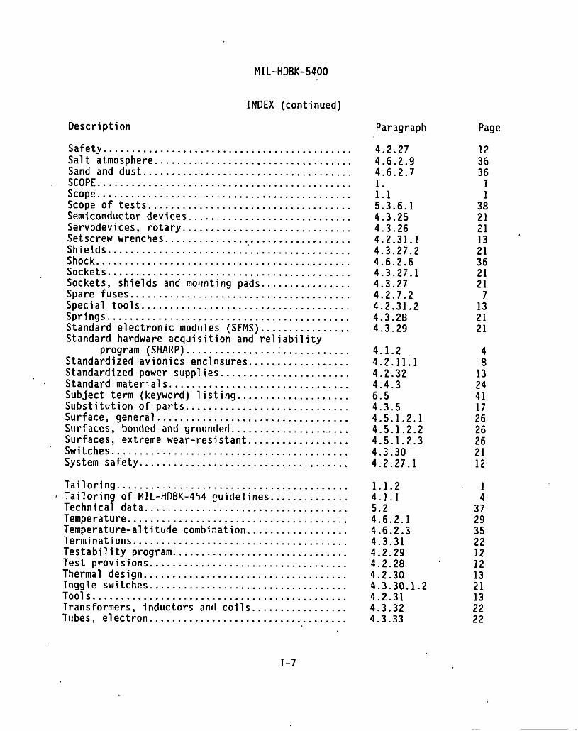
MIL-HDBK-5400
INDEX (continued)
Description
Safety ............................................Salt atmosphere ...................................Sand and dust .....................................SCOPE .............................................Scope ............”.................................Scope of tests ....................................Semiconductor devices .............................Servodevices, rotary ..............................Setscrew wrenches .................................Shields ............................................Shock .............................................Sockets ...........................................Sockets, shields and molmting pads ................Spare fuses .......................................Special tools .....................................
Standard electronic modules (SEAMS ).......Standard hardware acquisition and reliabi’
program (SHARP) .....................Standardized avionics enclosures .........Standardized oower suonlies ..............
Springs ...................................................ity................
. . . . . . . . .Standard mate~ial s.. .~~.................. ........Subject term (keyword) listing ....................Substitute on of parts .............................Surface, genera l..................................Surfaces, bonded and grnunded. .....................Surfaces, extreme wear-resistant ..................Switches ..........................................System safety ......................................
Tailoring ........................................., Tailoring of MIL-HllBK-454 guide lines ..............Technical data ....................................Temperature .......................................Temperature-altitude combination ..................Terminations ......................................Testabil ity program ...............................Test provisions ...................................Thermal design ....................................Tnggle switches ...................................Tools .............................................Transformers, inductors and coils...... ...........Tubes, electron ...................................
Paragraph
4.2.274.6.2.94.6.2.7
::15.3.6.14.3.254.3.264.2.31.14.3.27.24.6.2.64.3.27.14.3.274.2.7.24.2.31.24.3.284.3.29
4.1.24.2.11.14.2.324.4.36.54.3.54.5.1 .2.14.5.1 .2.24.5.1 .2.34.3.304.2.27.1
1.1.24.1.1
:::.2.14.6.2.34.3.314.2.294.2.2B4.2.304.3.30.1.24.2.314.3.324.3.33
I-7
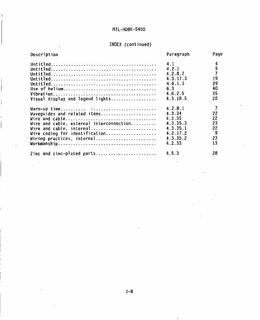
!MIL-HDBK-5400
INDEX (continued)
Description
Untitled ..........................................Untitled ..........................................Untitled ..........................................Untitled ..........................................Untitled ..........................................Use of helium .....................................Vibration .........................................Visual display and legend lights ..................
Warm-up time .......... ............Waveguides and related items, ,, .....Wire and cable ......................Wire and cable, external interconnectWire and cable, internal ............Wire coding for identificat ion......Wiring practices, internal ..........Workmanship ..........................
. . . . . . . . . . . . .
. . . . . . . . . . . . .
. . . . . . . . . . . . .ion..............................................................
I Zinc andzinc-pl ated parts ........................
Paragraph
4.14.2.14.2.8.24.3.17.34.6.1.16.34.6.2.54.3.18.5
4.2.8.14.3.344.3.354.3.35.34.3.35.14.2.17.24.3.35.24.2.33
4.5.3
Page
4
;1929403520
722222322
92313
28
I-8

/
STANDARDIZATION DOCUMENT IMPROVEMENT PROPOSAL
INSTRUCTIONS
1. Thepreparfng acthdtv must .Omnlmablocks1,2,3.and8.1.bf.ck1.bothtied.cunn.tn.mbmendI.tisIo.lonershouldb.oi..n.
2. Th.subtinmofti$formmuslcomplet.bl.cks4.S,6.and 7.
3. Th.PCoPtinoc.ctintvmum P,c.ndea,.plvwkhi.30davsIr.fnm..imoftheform.NOTE Thisfarmmarnotbausedtor.quasiCOC4-atdocuments, nor t. rqu.st waivers, or cladfication of rmjubenmnts on..”..1 contracts. C.ame.ms mbmin.d..shf.f.rrndoWI conatinmw Implyti.ri..tion1. wake nnv pertion of themfmmc9d d~ument 1s)m t0 amend conuactual re.mdremmm.
1, Wcuhwa MIM8ER 2. DOCUMENT DATE
I RECOMMEND A CHANGE: 4-mMIL-HDBK-5400 951130
WcuMENlmLE:LEcTRONICEQuIPMENT,AIRBORNE GENERAL GUIDELINESFOR
mm OF CHANGE Iklmw-m - d titi w .-. n-. AnRd ●.* shall .-.1
PSMON FOR PSCOMMFND&TlON
—
NAMS (Lu’ h W bti b. OSGANUATION
Amms5 - * Codd d. TELEPHONE 7.DaisSIJmlrrw(.kfudoArM Code) I —1
(11 cOINlwrcfaf:
t21 DSN:
.-,
NEVARWG ACTMTV
,NAMJ b. “TELsFno)iE — lIrr&dJ k c-)
cOMMA-R 111—
NAVAL AL8 WARFAFK -(2I =N
mBcsAfT -N
(9081 321+S70 624.2s70
A- W Z? Cd) ~mvm8ur -a~vwmw43mvs. c9Tacn
CO= 4.1.a.2B12*3M!afw4Y 6J7
M. Ou-l?ds— GWk9. 5203_ PM.
LAKDNPS1. W =733.6 700
Wt. 1403. FdI ~. V4 Z2M1.3486T~ (7031 758.2340 D3N 289.2340
. . “ . . . . ..,., ———.—. . . . . . . . . . . . .Farm l-z., “., .3 rrc— .9”,M7, .,. C!n,mr. ,..,,