Embed Size (px)
Citation preview

BA 141F/00/en/12.01 (b)52012215
Valid as of software version:V 1.0
Electronic insert FEL 50 Afor Liquiphant M/S (HT)PROFIBUS PA
Operating Instructions

Brief operating instructions Liquiphant M/S (HT), FEL 50 A PROFIBUS PA
2 Endress+Hauser
Brief operating instructions
These brief operating instructions (KA) show you how to configure your measuring device quickly and easily:
Safety instructions page 4.
Mounting See KA ...(Basic device),
table "Supplementary
documentation" p. 39
Wiring page 9.
Commissioning / addressing page 18/29
Operating elements page 17.
Configuration page 30.
Trouble-shooting page 34.
Always commence trouble-shooting with the checklist on page 34., and the trouble-shooting instructions in the Operating Instructions of the basic device (see table page 39.) if errors occur during commissioning or operation. The routine takes you directly to the cause of the problem and the appropriate remedial measures.
Returning devicesIf you return a device to Endress+Hauser for repairs or calibration, please note the information in the Operating Instructions ... (basic device), see also the table on "Supplementary documentation" page 39

Liquiphant M/S (HT), FEL 50 A PROFIBUS PA Contents
Endress+Hauser 3
Contents
Brief operating instructions . . . . . . . . . . . . . 2
Contents . . . . . . . . . . . . . . . . . . . . . . . . . . . . . . . . 3
1 Safety instructions . . . . . . . . . . . . . . . . 4
1.1 Intended application. . . . . . . . . . . . . . . . . . . . . 41.2 Mounting, commissioning, operation . . . . . . . . 41.3 Operational safety . . . . . . . . . . . . . . . . . . . . . . 41.4 Return . . . . . . . . . . . . . . . . . . . . . . . . . . . . . . . 51.5 Notes on safety conventions and icons . . . . . 5
2 Identification . . . . . . . . . . . . . . . . . . . . . 6
2.1 Device designation . . . . . . . . . . . . . . . . . . . . . 62.2 Delivery . . . . . . . . . . . . . . . . . . . . . . . . . . . . . . . 62.3 Certificates and approvals . . . . . . . . . . . . . . . 62.4 Registered trademarks . . . . . . . . . . . . . . . . . . 7
3 Mounting . . . . . . . . . . . . . . . . . . . . . . . . . 8
3.1 Incoming acceptance, transport and storage 83.2 Use and Mounting . . . . . . . . . . . . . . . . . . . . . . 8
4 Wiring . . . . . . . . . . . . . . . . . . . . . . . . . . . . 9
4.1 PROFIBUS PA Cable specifications . . . . . . . . . 94.2 Connection of the limit switch . . . . . . . . . . . . 114.3 Connection data . . . . . . . . . . . . . . . . . . . . . . 134.4 PROFIBUS PA M12 plug connector . . . . . . . 134.5 Potential equalisation . . . . . . . . . . . . . . . . . . 154.6 Degree of protection . . . . . . . . . . . . . . . . . . . 154.7 Post connection check . . . . . . . . . . . . . . . . . 16
5 Operation . . . . . . . . . . . . . . . . . . . . . . . . 17
5.1 Operation at a glance . . . . . . . . . . . . . . . . . . 175.2 On-site configuration/operation . . . . . . . . . . . 185.3 Communication with PROFIBUS PA . . . . . . . 20
6 Commissioning . . . . . . . . . . . . . . . . . . 29
6.1 Mounting and function testing . . . . . . . . . . . . 296.2 Commissioning with Commuwin II . . . . . . . . . 29
7 Maintenance . . . . . . . . . . . . . . . . . . . . . 32
8 Accessories . . . . . . . . . . . . . . . . . . . . . . . 33
9 Trouble-shooting . . . . . . . . . . . . . . . . 34
9.1 System error messages . . . . . . . . . . . . . . . . 349.2 Spare parts . . . . . . . . . . . . . . . . . . . . . . . . . . 359.3 Return . . . . . . . . . . . . . . . . . . . . . . . . . . . . . . 359.4 Software history . . . . . . . . . . . . . . . . . . . . . . . 36
9.5 Contact addresses of Endress+Hauser . . . . . 36
10 Technical data . . . . . . . . . . . . . . . . . . . . 37
10.1 Technical data at a glance . . . . . . . . . . . . . . 37

1 Safety instructions Liquiphant M/S (HT), FEL 50 A PROFIBUS PA
4 Endress+Hauser
1 Safety instructions
1.1 Intended application
The Liquiphant M FTL 50 (H)/51 (H)/51 C and Liquiphant S (HT*), FTL 70/71 with electronic insert FEL 50 A may only be used as a limit switch for liquids.Other applications are not permitted. They may violate the appropriate regulations, particularly in explosion-hazardous areas.
1.2 Mounting, start-up, operation
The Liquiphant M and Liquiphant S (HT) with electronic insert FEL 50 A is built to the state-of-the-art and to be fail-safe and meets the appropriate rules and EC directives. However, if you use it improperly or other than for its designated use, it may pose application-specific hazards, e.g. product overflow through incorrect mounting or configuration. Mounting, electrical connection, start-up, operation and maintenance of the measuring device must therefore be carried out exclusively by trained specialists authorised by the system operator. Technical personnel must have read and understood these operating instructions and must adhere to them. You may only undertake modifications or repair work to the device when it is expressly permitted by the operating manual.
1.3 Operational safety
Explosion-hazardous areaWhen using the measuring system in explosion-hazardous areas, you must keep to the appropriate national standards. The device possesses separate Ex documents (XA 154F, XA 158F, XA 159F) which form a component part of this documentation. Always follow the mounting regulations, connection data and safety instructions therein.• Make sure that the specialist personnel have received sufficient training.• Always keep to the measuring and safety conditions at the measuring points.
* HT = High temperature

Liquiphant M/S (HT), FEL 50 A PROFIBUS PA 1 Safety instructions
Endress+Hauser 5
1.4 Return
See KA ... (Basic device), table "Supplementary documentation" page 39
1.5 Notes on safety conventions and icons
To highlight safety-relevant or alternative procedures, we have set the following safety instructions for which each individual instruction is indicated with an appropriate pictogram.
Safety instructions
Type of protection
Electrical symbols
Icon Meaning
#Warning!"Warning" indicates activities or processes which - if improperly executed - could lead to serious injury to persons, to a safety risk or to destruction of the device.
" Caution!"Caution" indicates activities or processes which - if improperly executed - could lead to injury to persons or to incorrect functioning of the device.
! Note!"Note" indicates activities which - if improperly executed - could have an indirect impact on operation or trigger unexpected instrument actions.
0 Explosion protected, design tested apparatusIf this symbol appears on the nameplate of the device, the device can be used in a hazardous area or in a non-hazardous area, according to the approval.
-Hazardous areaIn the drawings of these operating instructions, this symbol indicates hazardous areas.– Devices located in hazardous areas or lines for such devices must possess
an appropriate type of protection.
.Safe area (non-hazardous area)In the drawings of these operating instructions, this symbol indicates non-hazardous areas.– Devices in non-hazardous areas must also be certified, if the connecting
lines run through a hazardous area.
% DC voltageA terminal at which DC voltage is applied or through which DC flows.
& ACA terminal at which (sine-form) alternating voltage is applied or through which AC flows.
) Ground connectionA grounded terminal, which, from the user's point of view, is already grounded using a grounding system.
* Protective earth connectionA terminal which must be grounded before other connections may be set up.
+Equipotential connectionA connection which must be connected to the grounding system of the equipment: this can, for example, be a potential matching line of a starshaped grounding system, depending on national or company practice.

2 Identification Liquiphant M/S (HT), FEL 50 A PROFIBUS PA
6 Endress+Hauser
2 Identification
2.1 Device designation
2.1.1 Nameplate
On the nameplate, you can find the following technical information:
Fig. 1 Information on the nameplate of the Liquiphant M with electronic insert FEL 50 A (Example)
2.1.2 Product structure
See KA ... (Basic device), table "Supplementary documentation" page 39.
2.2 Delivery
" Caution!Always note the instructions in chapter "Incoming acceptance, transport and storage" on page 8 concerning the unpacking, transport and storage of devices!
The delivery consists of:• Installed device• poss. accessories (see Chapter 8)
Supplementary device documentation:• Operating Instructions KA ... (Basic device)• Operating manual (this booklet)• Approval documentation: as far as not given in the operating manual
2.3 Certificates and approvals
CE symbol, Declaration of conformityThe instrument has been designed and tested according to the state of the art and left the factory in perfect functioning order. The device meets all the appropriate standards and regulations according to EN 61010 "Safety regulations for electrical measurement, control, and laboratory devices". Thus, the device meets the statutory requirements of
ENDRESS+HAUSERLIQUIPHANT M
FTL 5#–######A### #### mmin FTL 51
Order Code
L
Cer
tific
ate
Pro
cess
Con
nect
ion
-Len
gth
Ele
ctro
nics
Inse
r t
Ver
sion
Pro
tect
ion
Type

Liquiphant M/S (HT), FEL 50 A PROFIBUS PA 2 Identification
Endress+Hauser 7
EC directives. Endress+Hauser confirms successful testing of the device by affixing the CE mark.
PNO CertificationThe device was certified according to the PNO standard (Profile 3.0).
2.4 Registered trademarks
PROFIBUS ® is a registered trademark of PROFIBUS Nutzerorganisation e.V., Karlsruhe, Germany.

3 Installation Liquiphant M/S (HT), FEL 50 A PROFIBUS PA
8 Endress+Hauser
3 Installation
3.1 Incoming acceptance, transport and storage
3.1.1 Incoming acceptance
Check the packaging and the contents for damage.Check the shipment, make sure nothing is missing and that the scope of supply matches your order.
3.1.2 Storage
For storage and transport purposes, pack the instrument so that it is protected against impacts. The original packaging provides optimum protection.The permissible storage temperature is –50 °C…+80 °C.
3.2 Use and Mounting
See KA ... (Basic device), table "Supplementary documentation" page 39.

Liquiphant M/S (HT), FEL 50 A PROFIBUS PA 4 Wiring
Endress+Hauser 9
4 Wiring
# Warning!• When connecting Ex-certified devices, see the notes and wiring diagrams in the
Ex-specific supplement to these Operating Instructions. Please do not hesitate to contact your E+H representative if you have any questions.
4.1 PROFIBUS PA Cable specifications
Always use a twisted, screened two-wire cable. When installing in the hazardous area, keep to the following characteristic values (EN 50020, FISCO model):
The following cable types are suitable, for example:
Non-Ex area:• Siemens 6XV1 830-5BH10 (grey)• Kerpen CEL-PE/OSCR/PVC/FRLA FB-02YS(ST)YFL (grey)• Belden 3076F (orange)
Ex area:• Siemens 6XV1 830-5AH10 (blue)• Kerpen CEL-PE/OSCR/PVC/FRLA FB-02YS(ST+C)YFL (blue)
Maximum overall cable lengthThe maximum network expansion depends on the type of explosion protection and the cable specifications. The overall cable length is made up of the length of the main cable and the length of all spurs (> 1 m). Note the following points:• The highest permissible cable length is dependent on the cable type used:
Type A Type B
Cable structure twisted pair,screened
one or more twisted pairs, fully shielded
Wire size 0.8 mm2 (AWG 18)
0.32 mm2
(AWG 22)
Loop resistance(DC)
44 Ω/km 112 Ω/km
Impedance at 31.25 kHz 100 Ω ± 20% 100 Ω ± 30%
Attenuation constant at 39 kHz
3 dB/km 5 dB/km
Capacitive asymmetry 2 nF/km 2 nF/km
Envelope delay distortion (7.9 through 39 kHz)
1.7 µs/km *
Shield coverage 90% *
Maximum Cable length (incl. spurs > 1 m)
1900 m 1200 m
* not specified
Type A 1900 m
Type B 1200 m

4 Wiring Liquiphant M/S (HT), FEL 50 A PROFIBUS PA
10 Endress+Hauser
• If repeaters are used the maximum permissible cable length is doubled.A maximum of four repeaters are permitted between user and master.
Maximum spur lengthThe line between distribution box and field unit is described as a spur.In the case of non Ex-applications the maximum length of a spur depends on the number of spurs (> 1 m):
Number of field devicesIn systems that meet FISCO in the EEx ia type of protection, the line length is limited a maximum of 1000 m.Up to 32 stations are possible per segment in non-Ex areas or maximum 10 stations in hazardous area (EEx ia IIC). The actual number of users must be determined during configuration.
Bus terminationThe start and end of each field bus segment are always to be terminated with a bus terminator. With various junction boxes (not Ex-rated) the bus termination can be activated via a switch. If this is not the case a separate bus terminator must be installed. Note the following points in addition:• In the case of a branched bus segment the device furthest from the segment coupler
represents the end of the bus.• If the field bus is extended with a repeater then the extension must also be terminated
at both ends.
Shielding and groundingWhen planning the shielding and grounding for a field bus system, there are three important points to consider:• Electromagnetic compatibility (EMC)• Explosion protection• Safety of the personnel
To ensure the optimum electromagnetic compatibility of systems, it is important that the system components and above all the cables, which connect the components, are screened and that no portion of the system is unscreened.Ideally, the cable screening will be connected to the field devices' housings, which are usually metal. Since these housings are generally connected to the protective earth, the shield of the bus cable will thus be grounded many times.This approach, which provides the best electromagnetic compatibility and personnel safety, can be used without restriction in systems with good potential matching.In the case of systems without potential matching, a mains frequency (50 Hz) equalising current can flow between two grounding points, which in unfavorable cases, e.g. when it exceeds the permissible shield current, may destroy the cable. To prevent low-frequency equalising currents, it is wise with systems without potential matching system to connect the cable screening only on one side with the local ground (or protective earth) and connect all further ground points capacitively.
Further informationGeneral information and further notes regarding the wiring can be found in the BA 198F.
Number of spurs 1 ... 12 13... 14 15... 18 19... 24 25... 32
Maximum length per spur 120 m 90 m 60 m 30 m 1 m

Liquiphant M/S (HT), FEL 50 A PROFIBUS PA 4 Wiring
Endress+Hauser 11
4.2 Connection of the limit switch
4.2.1 Connection with cable gland
Procedure:1. Unscrew connection compartment cover from transmitter housing.2. Run the PROFIBUS cable through the appropriate cable entries.3. Connect the cables in accordance with the wiring diagram: see Fig. 5 and Fig. 6
" Caution!– The PROFIBUS cable can be damaged!
In systems without additional potential matching systems, line-frequency equalising currents may occur which damage the cable and/or the screen, should the cable screening be grounded at several points. In such cases the shielding of the cable is to be grounded on only one side,i.e. it must not be connected to the ground terminal of the housing. The shield that is not connected should be insulated!
– We recommend that the PROFIBUS not be looped using conventional cable glands. If you later replace even just one measuring device, the bus communication will have to be interrupted.
! Note!– The terminals for the PROFIBUS connection (1/2) possess integrated reverse
polarity protection. This ensures correct signal transmission via the field bus even if lines are confused.
– Conductor cross-section: maximum 2.5 mm2
– Observe the system's grounding concept.– Select the Bus address using the miniature switch.
4. Screw the connection compartment cover back onto the housing.
Fig. 5 Connection of transmitter with cable gland
max. 2.5 mm²
3 mm(1/8 in)
(max. AWG 14)
max. 4 mm²
(max. AWG 12)
FEL 50 A
ø5 … 9 mm(ø0.2 … 0.35 in)
M 20 x 1.5

4 Wiring Liquiphant M/S (HT), FEL 50 A PROFIBUS PA
12 Endress+Hauser
Fig. 6 Assignment of screw terminals
PROFIBUS PA line: Terminal No. 1: PA –Terminal No. 2: PA+conductor cross-section: maximum 2.5 mm2
4.2.2 Connection with PROFIBUS PA M12 plug-in connector
The Liquiphant PROFIBUS PA version with M12 plug-in connector is supplied completely wired. All you need to do is connect it to the bus with a pre-terminated cable.
Fig. 7 PROFIBUS PA M12 pin assignment
A = Protection cap for device plugB = Fieldbus device plugC = Socket insert (female)D = Device plug on housing (male)Pin assignment / Colour codes:1 = Brown wire: PA+2 = Unconnected3 = Blue line: PA–4 = Black line: Ground (Notes for connection see page 15)6 = Positioning slot
PA+PA–
1 2
U – : 9 V…32 V (DC)…
+PAPA -
FEL50A
HWOFF
ON
Address
SW
1 2 3 4 5 6 7 8
Socket insert (female)
Device plug on housing (male)
3 4
2 1
A B
4
1 2
C
D
3
5
6
7PA+
PA–
PA+
PA–
BK
BN
BU

Liquiphant M/S (HT), FEL 50 A PROFIBUS PA 4 Wiring
Endress+Hauser 13
7 = Positioning lug
4.3 Connection data
Cable entryCable gland: M20x1.5 or Pg 13.5Cable entry: G ½ or ½ NPTPROFIBUS PA M12 plug-in connector
Supply voltageAll the following voltages are terminal voltages directly at the device:
Current consumptionCurrent consumption over the whole voltage area is approx. 11 mA.
4.4 PROFIBUS PA M12 plug-in connector
! Note!This connector can only be used for a PROFIBUS PA device.
With PROFIBUS PA the connection system allows you to connect devices to the fieldbus using standardised mechanical connections such as branches and distributor elements. This connection technology using prefabricated distribution modules and plug-in connectors offers substantial advantages over conventional wiring:• Field devices can be removed, replaced or added at any time during normal
operation. Communications will not be interrupted.• This simplifies mounting and maintenance significantly.• Existing cable infrastructures can be used and expanded instantly, e.g. when
constructing new star distributors using 4-channel or 8-channel junction boxes.
Optionally, the Liquiphant can be supplied from the factory with a pre-installed fieldbus device plug-in connector. Field bus connectors for retrofitting can be ordered from E+H as a spare part (see page 35).
Connection data PROFIBUS PA
Ui ≤ 30 VDCIi ≤ 500 mAPi ≤ 5.5 WLi ≤ 10.0 µHCi ≤ 5 nF
Variant Terminal voltage
Minimum Maximum
Standard 9 V 32 V
EEx ia (FISCO model) 9 V 17.5 V
EEx ia (Entity concept) 9 V 24 V

4 Wiring Liquiphant M/S (HT), FEL 50 A PROFIBUS PA
14 Endress+Hauser
Fig. 8 Connectors for connecting to the PROFIBUS PA
A = Protection cap for device plugB = Fieldbus device plugC = Socket insert (female)D = Device plug on housing (male)
Pin assignment / color codes:1 = Brown wire: PA+2 = Unconnected3 = Blue line: PA–4 = Black line: Ground (Notes for connection see page 15)6 = Positioning slot7 = Positioning lug
Technical data (field bus connector):Connection cross section 0.75 mm2
Connector thread M20x1.5
Degree of protection IP 67 in accordance with DIN 40050 IEC 529
Contact surface CuZnAu
Housing material CuZn, surface Ni
Flammability V - 2 in accordance with UL - 94
Nominal current per contact 3 A
Nominal voltage 125...150 V DC in accordance with the VDE standard 01 10/ISO Group 10
Resistance to tracking KC 600
Volume resistance ≤ 8 mΩ in accordance with IEC 512 Part 2
Insulation resistance ≤ 1012 Ω in accordance with IEC 512 Part 2
150/300 mm45.0 mm(1.766")
M20*1.5M 12 x 1
A B
3 4
2 1
4
1 2
C
D
3
5
6
7PA+
PA–
PA+
PA–
BK
BN
BU

Liquiphant M/S (HT), FEL 50 A PROFIBUS PA 4 Wiring
Endress+Hauser 15
4.5 Potential matching system
For maximum EMC protection, e.g. near frequency convertors, it is advisable to connect the housing and cable screening using a potential matching line (PAL) (maximum wire cross-sectional area: 4 mm², fixed conductor).
Please pay attention to the following points:• Ground the device using the external ground terminal
(only for devices in hazardous areas).• The bus cable screening may not be interrupted.• Ground the screening at each end of the cable, and always try to keep the connecting
cable between the screening and ground as short as possible.• With large potential differences between the individual ground points, only one point
is connected with the reference ground. All the other screening ends are connected with an HF-compatible condenser with reference potential (e.g. ceramic condenser 10 nF/250 V~).
" Caution!Applications subject to explosion protection only have approval under certain conditions for multiple grounding of the protective screening, see EN 60079-14.
You can find further information on the structure and the grounding of the network in the operating manual BA 198F "PROFIBUS PA: Guideline on project planning and commissioning" and the PROFIBUS PA specification EN 50170 (DIN 19245).
4.6 Degree of protection
• Electronic insert: IP 20, NEMA 1• Housing: depending on version, see KA ... (Basic device)
table "Supplementary documentation" page 39

4 Wiring Liquiphant M/S (HT), FEL 50 A PROFIBUS PA
16 Endress+Hauser
4.7 Post connection check
Perform the following checks after completing electrical mounting of the measuring device:
Device condition and specifications Notes
Are cables or the device damaged (visual inspection)? −
Electrical connection of meter Notes
Does the supply voltage match the specifications on the nameplate?9...32 V DC
Do the cables comply with the specifications? see page 9
Do the cables have adequate strain relief? −
Are the cables correctly segregated by type?Without loops and crossovers?
−
Are the fieldbus cables correctly connected? See the wiring diagram inside the cover of the terminal compartment
Are all screw terminals firmly tightened? −
Have all the measures pertaining to grounding and potential matching been carried out correctly?
see page 15
Are all cable entries installed, firmly tightened and correctly sealed? Cables looped as “water traps”?
−
Are all housing covers installed and firmly tightened? −
PROFIBUS PA electrical connection Notes
Are all the connecting components (T-boxes, junction boxes, connectors, etc.) connected together correctly?
–
Has each field bus segment been terminated at both ends with a bus terminator?
–
Has the maximum length of the field bus cable been observed in accordance with the PROFIBUS specifications?
see page 9
Has the maximum length of the spurs been observed in accordance with the PROFIBUS specifications?
see page 10
Is the field bus cable fully shielded and correctly grounded? see page 10

Liquiphant M/S (HT), FEL 50 A PROFIBUS PA 5 Operation
Endress+Hauser 17
5 Operation
5.1 Operation at a glance
You have a number of options for configuring and commissioning the measuring device:
1. Configuration programsThe profile and device-specific parameters are primarily configured using the PROFIBUS DP/PA interface. For this, there are special configuration and/or operating programs from different manufacturers available to the user.
2. Miniature switchThe settings from the PROFIBUS PA device bus address can be made using the miniature switch on the surface of the FEL 50 A.
Fig. 9 Operation options for Liquiphant PROFIBUS PA
1 Configuration/operating programs for operation using PROFIBUS PA2 Miniature switch for addressing
1
2
1 2
+PAPA -
FEL50A
HWOFF
ON
AddressAddress
SW
1 2 3 4 5 6 7 8
OFF
ON
1 2 3 4 5 6 7 8
HW
SW

5 Operation Liquiphant M/S (HT), FEL 50 A PROFIBUS PA
18 Endress+Hauser
5.2 On-site configuration/operation
Only the device address can be set on the electronic insert.The two light emitting diodes indicate standby or the status of the tuning fork (covered/free).
Fig. 10 On-site operation for Liquiphant PROFIBUS PA
5.2.1 Setting the device address
Choice of device address• An address must be assigned to each PROFIBUS PA device. The process control
system only recognises the device when the address is set correctly.• In a PROFIBUS PA network, each address may be assigned only once.• Valid device addresses are inside the range of 0 to 126. All the devices are supplied
from the factory with the value 126.• The factory-set address 126 can be used for a functional test of the device and for
connections to a PROFIBUS PA network in operation. Subsequently, this address must be changed to be able to include additional devices.
Software AddressingSoftware addressing is only effective if DIP switch 8 is in the "ON" position (factory setting).For additional information on the addressing procedure, please consult operating manual BA198F, Chapter 5.7.
1 2
+PAPA -
FEL50A
HWOFF
ON
Address
SW
1 2 3 4 5 6 7 8
HWOFF
ON
Address
SW
1 2 3 4 5 6 7 8
Yellow LED on: Tuning fork coveredYellow LED flashing: Fault
Green LED on: Ready for operationGreen LED flashing: Communication
Plug for Service Tool

Liquiphant M/S (HT), FEL 50 A PROFIBUS PA 5 Operation
Endress+Hauser 19
Hardware Addressing
Fig. 11 Device addressing for Liquiphant PROFIBUS PA(Example: Address 10 Hardware Addressing)
Hardware addressing is only effective if DIP switch 8 is in the "OFF" position. The address is then set using DIP switches 1 to 7 according to the following table:
The newly set address becomes valid 10 seconds after the change.
Switch no. 1 2 3 4 5 6 7 8
Value in "ON" position 1 2 4 8 16 32 64 SW
Value in "OFF" position
0 0 0 0 0 0 0 HW
Example address 0 2 0 8 0 0 0 HW
1 2
+PAPA -
FEL50A
HWOFF
ON
Address
SW
1 2 3 4 5 6 7 8
OFF
ON
1 2 3 4 5 6 7 8
HW
SW
Hardwareaddressing
Example: 2 + 8 = 10 = Address
5 Operation Liquiphant M/S (HT), FEL 50 A PROFIBUS PA
20 Endress+Hauser
5.3 Communication PROFIBUS PA
5.3.1 System architecture
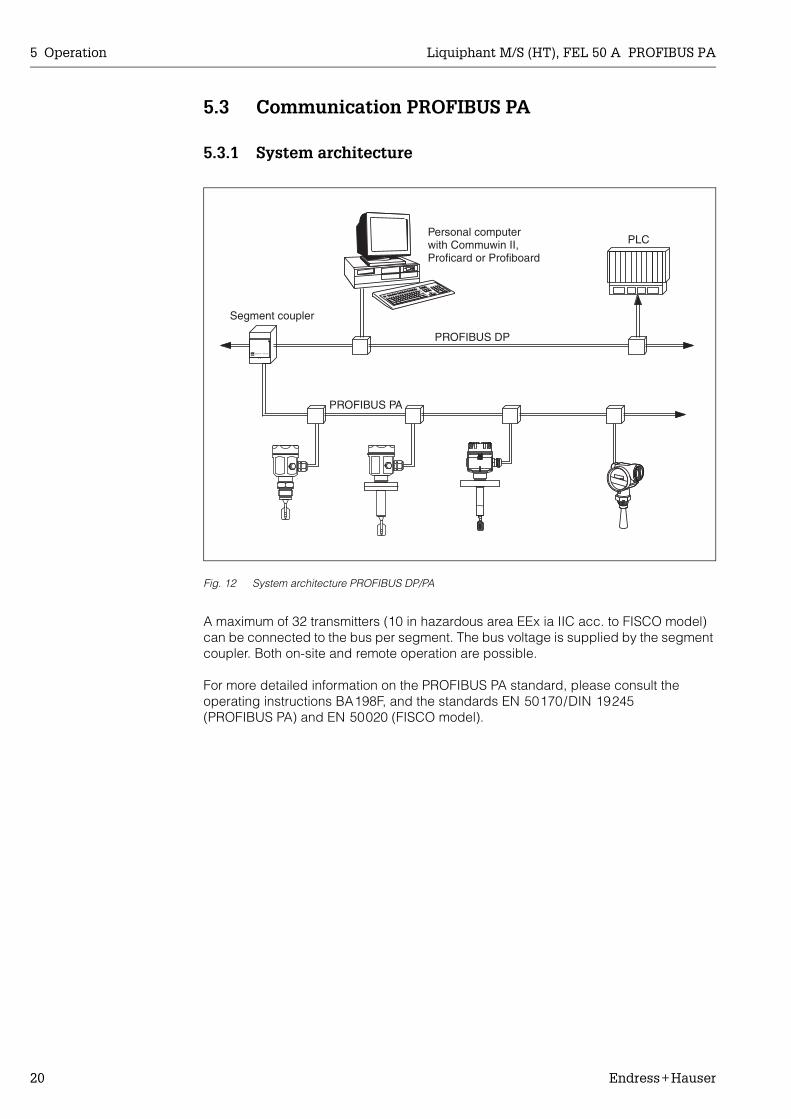
Fig. 12 System architecture PROFIBUS DP/PA
A maximum of 32 transmitters (10 in hazardous area EEx ia IIC acc. to FISCO model) can be connected to the bus per segment. The bus voltage is supplied by the segment coupler. Both on-site and remote operation are possible.
For more detailed information on the PROFIBUS PA standard, please consult the operating instructions BA198F, and the standards EN 50170/DIN 19245 (PROFIBUS PA) and EN 50020 (FISCO model).
Personal computerwith Commuwin II,Proficard or Profiboard
PLC
PROFIBUS DP
PROFIBUS PA
Segment coupler

Liquiphant M/S (HT), FEL 50 A PROFIBUS PA 5 Operation
Endress+Hauser 21
5.3.2 Device data bases (GSD)
The device data base (x.gsd) contains a description of the properties of a PROFIBUS PA device, e.g. which data transmission rate is supported by the device or which digital information in which format the PLC receives from the device.In addition, for project planning of a PROFIBUS DP network, you also require bitmap files with which the appropriate measuring point can be represented graphically in the project planning software.Each device receives an ID number from the PROFIBUS User Organisation (PNO). The name of the device data base (GSD) and the appropriate files are derive from this. The Liquiphant has the ID number 0x152b (hex) = 5419 (dec).
Reference sources• Internet (ftp server): ftp://194.196.152.203/pub/communic/gsd/fel50a.exe• CD-ROM with all GSD files for E+H devices; Order No.: 50097200• GSD library of the PROFIBUS User Organisation (PNO): http://www.PROFIBUS.com
Directory structureThe files are stored in the following directory structure:
• The GSD file in the "Standard" directory is used for PLCs which do not support an "Identifier Format" but only an "Identifier Byte", e.g. PLC5 from Allen-Bradley.
General database fileAlternatively to the specific GSD, the PNO makes a general database file available with the designation PA139720.gsd for devices with a discrete input block. This file supports the transmission of the main measured value.
When using the general database file, in the function "Ident Number" (V6H0) you must select the setting "Profile".
FEL50A/PA/Profile3/Revision1.0/
BMP
Eh152b_d.bmp
Eh152b_n.bmp
Eh152b_s.bmp
DIB
Info
GSD
Eh152b_d.dib
Eh152b_n.dib
Eh152b_s.dib
Standard/Eh3_152b.gsd
Typdat5x/Eh3152bx.200
Liesmich.pdfReadme.pdf
5 Operation Liquiphant M/S (HT), FEL 50 A PROFIBUS PA
22 Endress+Hauser
5.3.3 Cyclical data exchange
Block model of the Liquiphant M/S (HT) with FEL 50 A
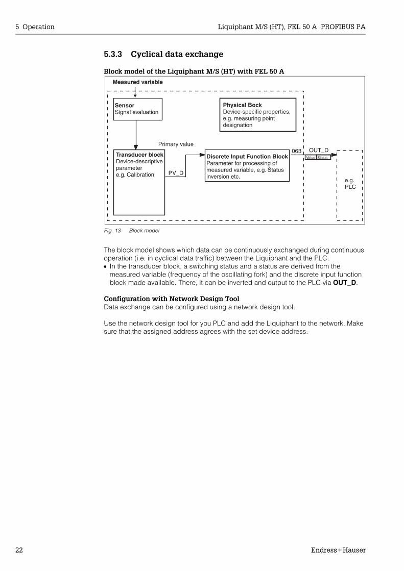
Fig. 13 Block model
The block model shows which data can be continuously exchanged during continuous operation (i.e. in cyclical data traffic) between the Liquiphant and the PLC. • In the transducer block, a switching status and a status are derived from the
measured variable (frequency of the oscillating fork) and the discrete input function block made available. There, it can be inverted and output to the PLC via OUT_D.
Configuration with Network Design ToolData exchange can be configured using a network design tool.
Use the network design tool for you PLC and add the Liquiphant to the network. Make sure that the assigned address agrees with the set device address.
OUT_D063
PV_D
Value Status
SensorSignal evaluation
e.g.PLC
Physical BockDevice-specific properties,e.g. measuring pointdesignation
Primary value
Measured variable
Discrete Input Function BlockParameter for processing ofmeasured variable, e.g. Statusinversion etc.
Transducer blockDevice-descriptiveparametere.g. Calibration

Liquiphant M/S (HT), FEL 50 A PROFIBUS PA 5 Operation
Endress+Hauser 23
Liquiphant → PLC (Input data)With the Data_Exchange service, a PLC can read input data from the Liquiphant in the form of an answer mail. The cyclic data telegram has the following structure:
Status CodesThe Status Codes OUT_D and PV_D are each 1byte in size and have the following meaning:
OUT_D (Discrete Input Function Block)
PV_D (Transducer Block)
IndexInput data
Data Access Data format/Remarks
0 Main measured value ->limit level: covered (1) / uncovered (0)
Read 1 Byte (0,1)
1 Status code for main measured value Read see "Status Codes"
Status code
Device status Meaning Main measured value
80 Hex GOOD OK (error-free)
x
84 Hex GOOD Parameter changed(Static revision was increased)
x
51 Hex UNCERTAIN Signal conversion inaccurateSensor EEPROM OK(Jam frequency reached, fork blocked or highly-viscous medium)
x
4C Hex BAD Initial value(Fail-safe-Mode aktiv)
Failsafe
44 Hex BAD Last usable value(Fail-safe-Mode aktiv)
Failsafe
10 Hex BAD Sensor Failure Failsafe
Status code
Device status Meaning Main measured value
80 Hex GOOD OK (error-free)
x
84 Hex GOOD Parameter changed(Static revision was increased)
x
51 Hex UNCERTAIN Signal conversion inaccurateSensor EEPROM OK(Jam frequency reached, fork blocked or highly-viscous medium)
x
12 Hex BAD Sensor error (Corrosion alarm, frequency too high, fork corroded)
x
0D Hex BAD Device error(Jam frequency reached, Sensor EEPROM not OK, fork removed from EEPROM blocked)
x
04 Hex BAD Fork exchanged or false CS in the sensor EEPROM x

5 Operation Liquiphant M/S (HT), FEL 50 A PROFIBUS PA
24 Endress+Hauser
5.3.4 Acyclical data exchange
With acyclic data exchange access, the instrument parameters in the physical, transducer and discrete input block can be accessed as can the device management with as PROFIBUS DP master class 2 (e.g. Commuwin II).
Slot/Index tablesThe device parameters are listed in the table below. You can access the parameters using the slot and index numbers. The individual blocks contain standard parameters, block parameters and manufacturer-specific parameters.
Device management
Discrete Input Function Block
Discrete Input Transducer Block
Parameter E+H Matrix(CW II)
Slot Index Size [bytes]
Type Read Write Storage Class
DIRECTORY_OBJECT_HEADER
1 0 12 Array of UNSIGNED16
x constant
COMPOSITE_LIST_DIR_ENTRIES
1 1 24 Array of UNSIGNED16
x constant
Parameter E+H Matrix(CW II)
Slot Index Size [bytes]
Type Read Write Storage Class
Standard parameter
BLOCK OBJECT 1 16 20 DS-32* x constant
ST_REVISION 1 17 2 UNSIGNED16 x non-vol.
TAG_DESC 1 18 32 OSTRING x x static
STRATEGY 1 19 2 UNSIGNED16 x x static
ALERT_KEY 1 20 1 UNSIGNED8 x x static
TARGET_MODE 1 21 1 UNSIGNED8 x x static
MODE_BLK 1 22 3 DS-37* x dynamic
ALARM_SUM 1 23 8 DS-42* x dynamic
BATCH 1 24 10 DS-67* x x static
Gap 1 25
Block parameter
OUT_D V6H2 (value)V6H3 (Status)
1 26 2 DS-34* x dynamic
CHANNEL 1 30 2 UNSIGNED16 x x static
INVERT V3H3 1 31 1 UNSIGNED8 x x static
FAIL_SAFE_TYPE V1H0 1 36 1 UNSIGNED8 x x static
FAIL_SAFE_VAL_D 1 37 1 UNSIGNED8 x x static
SIMULATE 1 40 3 DS-51 x x static
E+H Parameter
VIEW_1 FB 1 56 13+2 OSTRING x
Parameter E+H Matrix(CW II)
Slot Index Size [bytes]
Type Read Write Storage Class
Standard parameter
BLOCK OBJECT 1 61 20 DS-32* x constant
ST_REVISION 1 62 2 UNSIGNED16 x non-vol.
TAG_DESC 1 63 32 OSTRING x x static
STRATEGY 1 64 2 UNSIGNED16 x x static
ALERT_KEY 1 65 1 UNSIGNED8 x x static

Liquiphant M/S (HT), FEL 50 A PROFIBUS PA 5 Operation
Endress+Hauser 25
Physical Block
TARGET_MODE 1 66 1 UNSIGNED8 x x static
MODE_BLK 1 67 3 DS-37* x dynamic
ALARM_SUM 1 68 8 DS-42* x dynamic
Block parameter
PV_D V0H0 1 73 DS-34 constant
E+H Parameter
FREQ_ACT_BASE V0H8 1 84 4 FLOAT x dynamic
DENSITY_SWITCH V3H2 1 85 1 UNSIGNED8 x x static
FREQ_AIR_BASE V7H0 1 86 2 UNSIGNED16 x non-vol.
FREQ_SWITCH_LOW_LD V7H1 1 87 2 UNSIGNED16 x x static
FREQ_SWITCH_HIGH_LD V7H2 1 88 2 UNSIGNED16 x x static
FREQ_SWITCH_LOW_HD V7H1 1 89 2 UNSIGNED16 x x static
FREQ_SWITCH_HIGH_HD V7H2 1 90 2 UNSIGNED16 x x static
TIME_DELAY_COVER V3H0 1 95 4 FLOAT x x static
TIME_DELAY_FREE V3H1 1 96 4 FLOAT x x static
OVERFILL_PROTECTION V1H8 1 100 1 UNSIGNED8 x x static
VIEW_1 TB 1 105 13 x
Parameter E+H Matrix(CW II)
Slot Index Size[bytes]
Type Read Write Storage Class
Standard Parameter
BLOCK OBJECT 0 16 20 DS-32* x constant
ST_REVISION 0 17 2 UNSIGNED16 x non-vol.
TAG_DESC 0 18 32 OSTRING x x static
STRATEGY 0 19 2 UNSIGNED16 x x static
ALERT_KEY 0 20 1 UNSIGNED8 x x static
TARGET_MODE 0 21 1 UNSIGNED8 x x static
MODE_BLK 0 22 3 DS-37* x dynamic
ALARM_SUM 0 23 8 DS-42* x dynamic
SOFTWARE_REVISION 0 24 16 OSTRING x constant
HARDWARE_REVISION 0 25 16 OSTRING x constant
DEVICE_MAN_ID 0 26 2 UNSIGNED16 x constant
DEVICE_ID 0 27 16 OSTRING x constant
DEVICE_SER_NUMBER VAH5 0 28 16 OSTRING x constant
DIAGNOSIS 0 29 4 OSTRING x dynamic
DIAGNOSIS_EXTENSION 0 30 6 OSTRING x dynamic
DIAGNOSIS_MASK 0 31 4 OSTRING x constant
DIAGNOSIS_MASK_EXTENSION
0 32 6 OSTRING x constant
DEVICE_CERTIFICATION 0 33 32 OSTRING x constant
WRITE_LOCKING V9H9 0 34 2 UNSIGNED16 x x non-vol.
FACTORY_RESET V9H5 0 35 2 UNSIGNED16 x x static
DESCRIPTOR VAH0 0 36 32 OSTRING x x static
DEVICE_MESSAGE 0 37 32 OSTRING x x static
DEVICE_INSTAL_DATE 0 38 8 OSTRING x x static
LOCAL_OP_ENA 0 39 0 not supported x x non-vol.
IDENT_NUMBER_SELECTOR
V6H0 0 40 1 UNSIGNED8 x x static
Parameter E+H Matrix(CW II)
Slot Index Size [bytes]
Type Read Write Storage Class

5 Operation Liquiphant M/S (HT), FEL 50 A PROFIBUS PA
26 Endress+Hauser
E+H Parameter
ACTUAL_ERROR 0 54 2 Uinteger16 x dynamic
LAST_ERROR 0 55 2 Uinteger16 x x dynamic/non-vol.
UP_DOWN_FEAT_SUPPORT
0 56 1 OSTRING x constant
DEVICE_BAS_ADDRESS 0 59 1 Integer8 x dynamic
DEVICE_SOFTWARE_NR 0 60 2 Uinteger16 x constant
DEVICE_ID_NUM 0 70 2 Uinteger16 x constant
VIEW_1 PB 0 71
Parameter E+H Matrix(CW II)
Slot Index Size[bytes]
Type Read Write Storage Class

Liquiphant M/S (HT), FEL 50 A PROFIBUS PA 5 Operation
Endress+Hauser 27
5.3.5 Parameter access with Commuwin II
Using a PROFIBUS DP master class 2 such as Commuwin II, you can access the block parameters. Commuwin II runs on an IBM compatible PC or Notebook. The computer must be equipped with a PROFIBUS interface, i.e. PROFIBOARD for PCs and PROFICARD for Notebooks. During system integration, the computer is logged-on as a master class 2.
Connection• Profiboard for connection to PC• Proficard for connection to laptop
Creation of device list• Operation requires the mounting of the server PA-DPV1. Selecting "PA-DPV1" in the
menu "Connection setup" sets up the connection and an empty device list appears.• The device list with the tags is generated with the "Create with tag" checkbox.• There are two operating modes:
– Select E+H standard operation by clicking the device name.– Select the profile operation of the PROFIBUS standard blocks by clicking the
appropriate block (e.g. "DI" for the discreet input block of the Liquiphant).You can specify a tag name for each block.
• Configure the system using the "Device Data" menu.
"Device Data" menuYou can select between operation using a matrix or the graphic desktop using the Device Data menu.
• With matrix operation, the devices and/or the profile parameters are loaded into a matrix. In the case of standard option, this is the E+H standard matrix, in the case of profile operation, this is the block matrix of the selected block. You can change a parameter when the appropriate matrix field has been selected.
• With graphical operation, the operation sequence is represented in a series of images with parameters. The images "Status" and "Calibration" are available.
The meaning of the parameters and configuration sequence are described in Chap. 6.
Click here forstandard operation
Click here for profileoperation of theDiscrete Input Block

5 Operation Liquiphant M/S (HT), FEL 50 A PROFIBUS PA
28 Endress+Hauser
Fig. 14 Graphic operation with "Status"
Fig. 15 Graphic operation with "Calibration"
! Note!You can find further information on the Commuwin II operating program in the operating instructions BA 124F.

Liquiphant M/S (HT), FEL 50 A PROFIBUS PA 6 Commissioning
Endress+Hauser 29
6 Commissioning
6.1 Mounting and function check
Make sure that the Mounting and connection checks have been carried out before you commission your measuring point:• "Connection check" checklist (see page 16).
6.2 Commissioning with Commuwin II
As soon as you have connected the device to the PA bus and switched on the power supply, the Liquiphant limit switch is operational. This is indicated by the green operation LED. If the LED is flashing, then the device is communicating. The device was preset before leaving the factory.
1. Start Commuwin II and set up the connection to the bus via the server PA-DPV1. After this, create the device list, define the device address and select "Liquiphant" by clicking.
2. Click the matrix icons. The Commuwin II operating matrix is displayed.
Fig. 3 Commuwin II user interface

6 Commissioning Liquiphant M/S (HT), FEL 50 A PROFIBUS PA
30 Endress+Hauser
6.2.1 Operation using Commuwin II matrix
Note: If the device has been put into WHG mode, the matrix is automatically locked.This lock can only be lifted with VH99 = 33998 + VH18 = STANDARD.
Matrix field Meaning Selection/Input
V3H2 Changing the density factor >0.7 g/cm³>0.5 g/cm³
V3H3 Inversion of the output value Not inverted: Sensor covered → Output "1"Inverted: Sensor covered → Output "0"
V3H0V3H1
Setting the delay times 0.5...60 seconds
VAH0 Assignment of the TAG Maximum 32 characters
V1H0 Failure response FSAFE VALUE:→ Output of fail-safe value ∼ VH21 input in the Discrete Input Block (FSAFE_VAL_D)
WRONG VALUE:→ Output of detected value
LAST_GOOD_VALUE:→ Output of the last valid value
See page 23: → OUT_DDevice status = BAD
VH99 Unlocking the matrix 0 - xxxx locks 245733998 enables VH18 selection
VH18 Operating mode STANDARDWHG
VH96 Simulation DISABLEENABLE (VH00 is manipulated via VH97 (0.1))
VH97 Simulation value 0,1 → Simulation from VH00

Liquiphant M/S (HT), FEL 50 A PROFIBUS PA 6 Commissioning
Endress+Hauser 31
6.2.2 Commuwin II operating matrix
H9
SE
CU
RIT
Y
LOC
KIN
G(S
elec
tion)
H8
ME
AS
UR
ED
FR
EQ
.(D
isp
lay)
OV
ER
SP
ILL
PR
OT.
(Op
tions
)
H7
DE
VIC
E P
RO
FILE
(Dis
pla
y)
SIM
ULA
TIO
N
VALU
E(I
nput
, Ser
vice
)
H6
SIM
ULA
TIO
N(S
elec
tion,
Ser
vice
)
H5
SO
FTW
AR
E R
ES
ET
(Inp
ut, S
ervi
ce)
SE
RIA
L N
UM
BE
R(D
isp
lay)
H4
H3
INV
ER
T(S
elec
tion)
OU
T S
TATU
S(D
isp
lay)
SO
FTW
AR
E N
O.
(Dis
pla
y, S
ervi
ce)
H2
DE
NS
ITY
FA
CTO
R(S
elec
tion)
OU
T VA
LUE
(Dis
pla
y)
SW
ITC
H-O
FF
VALU
E(D
isp
lay,
Ser
vice
)
H1
OFF
DE
LAY
TIM
E(I
nput
)
DE
VIC
E A
DD
RE
SS
(Dis
pla
y)
SW
ITC
H-O
N V
ALU
E(D
isp
lay,
Ser
vice
)
LAS
T D
IAG
N. C
OD
E(D
isp
lay,
Ser
vice
)
H0
PR
IMA
RY
VA
LUE
(Dis
pla
y)
FSA
FE V
ALU
EFA
IL-S
AFE
MO
DE
(Sel
ectio
n)
ON
DE
LAY
TIM
E(I
nput
)
MA
NU
FAC
T. G
SD
IDE
NT
NU
MB
ER
(Sel
ectio
n)
ZE
RO
FR
EQ
UE
NC
Y(D
isp
lay,
Ser
vice
)
DIA
GN
OS
TIC
CO
DE
(Dis
pla
y, S
ervi
ce)
DE
SC
RIP
TOR
(Inp
ut)
V0
CA
LIB
RAT
ION
V1
SA
FETY
SE
TTIN
GS
V2
V3
EX
TEN
DE
D C
AL.
V4
V5
V6
PR
OFI
BU
S P
AR
AM
:
V7
SE
NS
OR
DAT
A
V8
V9
SE
RV
ICE
/ S
IMU
LATE
VA CO
MM
UN
ICAT
ION

7 Maintenance Liquiphant M/S (HT), FEL 50 A PROFIBUS PA
32 Endress+Hauser
7 Maintenance
See KA ... (Basic device), table "Supplementary documentation" page 39.

Liquiphant M/S (HT), FEL 50 A PROFIBUS PA 8 Accessories
Endress+Hauser 33
8 Accessories
There is a range of accessories available for the Liquiphant. These can be ordered separately from Endress+Hauser.
Commuwin IIOperating program for intelligent devices → Order No.: FXS 113-###
ProficardFor connection of a laptop to the PROFIBUS → Order No.: 016570-5260
ProfiboardFor connection of a PC to the PROFIBUS → Order No.: 52005721
For additional accessories for the Liquiphant, see KA ... (Basic device) table page 39..

9 Troubleshooting Liquiphant M/S (HT), FEL 50 A PROFIBUS PA
34 Endress+Hauser
9 Troubleshooting
9.1 System error messages
For other error possiblilities, see KA ... (Basic device) table page 39.
Code Error description Cause Action
101 A Checksum errorTotal reset and recalib. req.
• Reset• If alarm still present after
reset, replace electronics
102 A Checksum errorTotal reset and recalib. req.
• Device switched off before data was saved
• EMC problem• E2PROM defective
• Reset
• Avoid EMC problems• If alarm still present after
reset, replace electronics
125 A Sensor defective • Fork removed• Chopping frequency reached
• Insert fork• Check fork for blockage and
remove same as necessary
W103 Initialisation active Device start-up after reset Wait
Tab. 1 System error messages

Liquiphant M/S (HT), FEL 50 A PROFIBUS PA 9 Troubleshooting
Endress+Hauser 35
9.2 Spare parts
For spare parts KA ... (Basic device) table "Supplementary documentation" page 39.
! Note!You can order spare parts directly from your E+H service organisation using the serial number which is printed on the transmitter nameplate (see page 6). The corresponding spare part number is found on every spare part. Installation instructions are printed on the enclosed package insert.If the device designation changes, you must order a changed nameplate. You must then transfer the data for the new device to the changed nameplate and then fix the plate to the housing of the Liquiphant. See information in package insert.
" Caution!• It is not possible to convert a standard device into an Ex-system by replacing parts.• When repairing certified device, keep to the appropriate regulations.• With FM approved devices, it is forbidden to make changes to the device which are
not expressly approved in the operating instructions. A violation of this ban may make the approval for operating this device null and void.
9.3 Return
See KA ... (Basic device) table "Supplementary documentation" page 39.

9 Troubleshooting Liquiphant M/S (HT), FEL 50 A PROFIBUS PA
36 Endress+Hauser
9.4 Software history
9.5 Contact addresses of Endress+Hauser
On the rear page of these operating instructions, you can find the contact addresses of Endress+Hauser, to whom you should address your queries.
Software version / date
Changes to software Changes to documentation
V 1.00 / 10.2001 Original software.Compatible with:
– Commuwin II (version 2.05.03 and higher)

Liquiphant M/S (HT), FEL 50 A PROFIBUS PA 10 Technical data
Endress+Hauser 37
10 Technical data
10.1 Technical data at a glance
Application
Application Maximum or minimum detection in tanks or piping with fluids of all types, also in hazardous areas and in the food and pharmaceuticals industries.
Function and system design
Measuring principle The tuning fork of the sensor oscillates in resonance frequency. This frequency is reduced when covered with liquid. The change in frequency then activates a limit switch.
Measuring device The device possesses a digital output with PROFIBUS PA protocol.
Input variables
Measured variable Level (limit value)
Fluid density Configuration using Commuwin II: > 0.5 g/cm3 or > 0.7 g/cm3
Output variables
Output signal • PROFIBUS PA
Signal on alarm Failure information can be opened using the following interfaces:• Flashing yellow LED• Status code• Diagnosis code
Power supply
Electrical connections • 3 screw terminals• PROFIBUS PA M12 plug-in connector
Cable entries Cable gland: M20x1.5 or Pg 13.5Cable entry: G ½ or ½ NPTPROFIBUS PADiscrete-Input-Block M12 plug-in connector
Supply voltage Two-core cable connection, 9...32 V DC
Power consumption 100...350 mW
GN YEFEL 50A
Setting
OUT_D = 0PA-Bussignal
Level limit
not inverted
inverted
OUT_D = 1PA-Bussignal
OUT_D = 1PA-Bussignal
OUT_D = 0PA-Bussignal

10 Technical data Liquiphant M/S (HT), FEL 50 A PROFIBUS PA
38 Endress+Hauser
Measuring accuracy
Reference operating conditions
• Ambient temperature: 23 °C• Medium temperature: 23 °C• Fluid density: 1 g/cm3 (water)• Medium viscosity: 1 mm2/s• Medium pressure: 0 bar• Sensor Mounting: vertical from above• Density setting: > 0.7
Accuracy • Measuring error: specified constructively max. ±1 mm• Repeatability: 0.1 mm• Switching hysteresis: approx. 2 mm• Impact of medium temperature: max. +1.4...–2.8 mm (–50...+150 °C)• Impact of medium density: max. +4.8...–3.5 mm (0.5...1.5 g/cm3)• Influence of medium pressure: max. 0...–2.5 mm (0 ...64 bar)
Operating conditions
Installation conditions
Installation instructions See KA ... (Basic device) table page 39.
Environment conditions
Ambient temperature –50... +70 °CFor operation outdoors with strong sunlight penetration, you should use a protective cover.
Storage temperature –50...+80 °C
Climate class IEC 68, Part 2-38, Fig. 2a
Degree of protection Polyester, steel and aluminium housing: IP 66 / IP 67 to EN 60529Aluminium housing (EEx d, EEx de): IP 66 / IP 68 to EN 60529 (1 m, 24h)
Vibration resistance IEC 68, Part 2-6; (10...55 Hz, 0.15 mm, 100 cycles)
Electromagnetic compatibility (EMC)
• Interference emission to EN 61326; Equipment Class B• Interference immunity to EN 61326; Appendix A (Industrial sector, 10 V/m)
and NAMUR recommendation NE 21 (EMC).
Process conditions
Process temperature range
Liquiphant M: –50...+150 °CLiquiphant S (HT): –60...+280 °C (optionally 300 °C)(For exceptions, see Process Connections)
Process pressure limits –1...+64 bar across complete temperature range(For exceptions, see Process Connections)
State of aggregation Fluid
Density min. 0.5 g/cm3
Viscosity maximum 10’000 mm2/s
Solid matter maximum dia. 5 mm
Mechanical construction
Design / dimensions See KA ... (Basic device) table "Supplementary documentation" page 39.
Weight See KA ... (Basic device) table "Supplementary documentation" page 39.
Materials See KA ... (Basic device) table "Supplementary documentation" page 39.

Liquiphant M/S (HT), FEL 50 A PROFIBUS PA 10 Technical data
Endress+Hauser 39
Process connection See KA ... (Basic device) table page 39.
User interface
Operating concept • On-site operation: Miniature switch for addressing• Commuwin II
Display 1 green LED: Standby/communication1 yellow LED: Covered status of tuning fork/error display
Certificates and approvals
CE mark The measuring system is in conformity with the statutory requirements of the EC Directives. Endress+Hauser confirms successful testing of the device by affixing the CE mark.
Overspill protection to WHG
External standards and guidelines
EN 60529Degrees of protection by housing (IP code)EN 61010Protection Measures for Electrical Equipment for Measurement, Control, Regulation and Laboratory Procedures.EN 61326Interference emission (Equipment Class B), interference immunity (Appendix A - Industrial sector)NAMURAssociation for Standards for Control and Regulation in the Chemical Industry
Ex Approvals ATEX II 1/2 G+D EEx ia IIC T6 _________________________________ XA 154FATEX II 1/2 G EEx ia IIC T6
( Including warning "Electrostatic discharge") __________________ XA 158F ATEX II 1 G EEx ia IIC T6 ______________________________________ XA 159FATEX II 1/2 G EEx d IIC T6 _____________________________________XA 031FATEX II 1/2 G EEx de IIC T6 ____________________________________XA 108F
Ordering information
The E+H service organisation can provide detailed ordering information and information on the order codes on request.
Accessories
See page 33.
Supplementary documentation
Documentation • SI 027F "PROFIBUS" (Systeminformation)
• TI 328F "Liquiphant M FTL 50/FTL 51 H" (Technical Information)• TI 347F "Liquiphant M FTL 51 C" (Technical Information)• TI 354F "Liquiphant S FTL 70/FTL 71" (Technical Information)
• KA 143F "Liquiphant M FTL 50/FTL 51" (Operating Instructions)• KA 144F "Liquiphant M FTL 50 H/FTL 51 H" (Operating Instructions)• KA 162F "Liquiphant M FTL 51 C" (Operating Instructions)• KA 163F "Liquiphant M FTL 50-########7#" (Operating Instructions)• KA 164F "Liquiphant M FTL 50 H-########7#" (Operating Instructions)• KA 172F "Liquiphant S FTL 70/FTL 71" (Operating Instructions)• KA 173F "Liquiphant S FTL 70/71 -########7##" (Operating Instructions)
• BA 198F "PROFIBUS DP/PA: Guidelines on project planning and commissioning" (Operating Instructions)

Members of the Endress+Hauser Group
BA 141F/00/en/12.01 (b)52012215CCS / FM6
Europe
Austria Endress+Hauser Ges.m.b.H.WienTel. (01) 88056-0, Fax (01) 88056-35
Belarus BelorgsintezMinskTel. (0172) 263166, Fax (0172) 263111
Belgium / Luxembourg Endress+Hauser N.V.BrusselsTel. (02) 2480600, Fax (02) 2480553
BulgariaINTERTECH-AUTOMATIONSofiaTel. (02) 664869, Fax (02) 9631389
Croatia Endress+Hauser GmbH+Co.ZagrebTel. (01) 6637785, Fax (01) 6637823
CyprusI+G Electrical Services Co. Ltd.NicosiaTel. (02) 484788, Fax (02) 484690
Czech Republic Endress+Hauser GmbH+Co.PrahaTel. (026) 6784200, Fax (026) 6784179
Denmark Endress+Hauser A/SSøborgTel. (70) 131132, Fax (70) 132133
EstoniaELVI-AquaTartuTel. (7) 441638, Fax (7) 441582
Finland Endress+Hauser OyEspooTel. (09) 8676740, Fax (09) 86767440
France Endress+Hauser S.A.HuningueTel. (389) 696768, Fax (389) 694802
Germany Endress+HauserMesstechnik GmbH+Co.Weil am RheinTel. (07621) 975-01, Fax (07621) 975-555
Great Britain Endress+Hauser Ltd.ManchesterTel. (0161) 2865000, Fax (0161) 9981841
GreeceI & G Building Services Automation S.A.AthensTel. (01) 9241500, Fax (01) 9221714
HungaryMile Ipari-ElektroBudapestTel. (01) 2615535, Fax (01) 2615535
IcelandBIL ehfReykjavikTel. (05) 619616, Fax (05) 619617
IrelandFlomeaco Company Ltd.KildareTel. (045) 868615, Fax (045) 868182
Italy Endress+Hauser S.p.A.Cernusco s/N MilanoTel. (02) 921921, Fax (02) 92107153
LatviaRino TKRigaTel. (07) 312897, Fax (07) 312894
LithuaniaUAB "Agava"KaunasTel. (07) 202410, Fax (07) 207414
Netherland Endress+Hauser B.V.NaardenTel. (035) 6958611, Fax (035) 6958825
Norway Endress+Hauser A/STranbyTel. (032) 859850, Fax (032) 859851
Poland Endress+Hauser Polska Sp. z o.o.WarszawyTel. (022) 7201090, Fax (022) 7201085
PortugalTecnisis - Tecnica de Sistemas IndustriaisLinda-a-VelhaTel. (21) 4267290, Fax (21) 4267299
RomaniaRomconseng S.R.L.BucharestTel. (01) 4101634, Fax (01) 4101634
Russia Endress+Hauser Moscow OfficeMoscowTel. (095) 1587564, Fax (095) 1589871
SlovakiaTranscom Technik s.r.o.BratislavaTel. (7) 44888684, Fax (7) 44887112
Slovenia Endress+Hauser D.O.O.LjubljanaTel. (061) 1592217, Fax (061) 1592298
Spain Endress+Hauser S.A.Sant Just DesvernTel. (93) 4803366, Fax (93) 4733839
Sweden Endress+Hauser ABSollentunaTel. (08) 55511600, Fax (08) 55511655
Switzerland Endress+Hauser AGReinach/BL 1Tel. (061) 7157575, Fax (061) 7111650
TurkeyIntek Endüstriyel Ölcü ve Kontrol SistemleriIs-tanbulTel. (0212) 2751355, Fax (0212) 2662775
UkrainePhotonika GmbHKievTel. (44) 26881, Fax (44) 26908
Yugoslavia Rep.Meris d.o.o.BeogradTel.(11) 4441966, Fax (11) 4441966
Africa
EgyptAnasiaHeliopolis/CairoTel. (02) 4179007, Fax (02) 4179008
MoroccoOussama S.A.CasablancaTel. (02) 241338, Fax (02) 402657
South Africa Endress+Hauser Pty. Ltd.SandtonTel. (011) 4441386, Fax (011) 4441977
TunisiaControle, Maintenance et RegulationTunisTel. (01) 793077, Fax (01) 788595
America
Argentina Endress+Hauser Argentina S.A.Buenos AiresTel. (01) 145227970, Fax (01) 145227909
BoliviaTritec S.R.L.CochabambaTel. (042) 56993, Fax (042) 50981
Brazil Samson Endress+Hauser Ltda.Sao PauloTel. (011) 50313455, Fax (011) 50313067
Canada Endress+Hauser Ltd.Burlington, OntarioTel. (905) 6819292, Fax (905) 6819444
Chile Endress+Hauser Chile Ltd.SantiagoTel. (02) 3213009, Fax (02) 3213025
ColombiaColsein Ltda.Bogota D.C.Tel. (01) 2367659, Fax (01) 6104186
Costa RicaEURO-TEC S.A.San JoseTel. (02) 961542, Fax (02) 961542
EcuadorInsetec Cia. Ltda.QuitoTel. (02) 269148, Fax (02) 461833
GuatemalaACISAAutomatizacionYControlIndustrial S.A.Ciudad de Guatemala, C.A.Tel. (03) 345985, Fax (03) 327431
Mexico Endress+Hauser S.A. de C.V.Mexico CityTel. (5) 5682405, Fax (5) 5687459
ParaguayIncoel S.R.L.AsuncionTel. (021) 213989, Fax (021) 226583
UruguayCircular S.A.MontevideoTel. (02) 925785, Fax (02) 929151
USA Endress+Hauser Inc.Greenwood, IndianaTel. (317) 535-7138, Fax (317) 535-8498
VenezuelaControval C.A.CaracasTel. (02) 9440966, Fax (02) 9444554
Asia
China Endress+Hauser Shanghai
Instrumentation Co. Ltd.ShanghaiTel. (021) 54902300, Fax (021) 54902303
Endress+Hauser Beijing OfficeBeijingTel. (010) 68344058, Fax: (010) 68344068
Hong Kong Endress+Hauser HK Ltd.Hong KongTel. 25283120, Fax 28654171
India Endress+Hauser (India) Pvt Ltd.MumbaiTel. (022) 8521458, Fax (022) 8521927
IndonesiaPT Grama BazitaJakartaTel. (21) 7975083, Fax (21) 7975089
Japan Sakura Endress Co. Ltd.TokyoTel. (0422) 540613, Fax (0422) 550275
Malaysia Endress+Hauser (M) Sdn. Bhd.Petaling Jaya, Selangor Darul EhsanTel. (03) 7334848, Fax (03) 7338800
PakistanSpeedy AutomationKarachiTel. (021) 7722953, Fax (021) 7736884
Papua-NeuguineaSBS Electrical Pty LimitedPort MoresbyTel. 3251188, Fax 3259556
Philippines Endress+Hauser Philippines Inc.Metro ManilaTel. (2) 3723601-05, Fax (2) 4121944
Singapore Endress+Hauser (S.E.A.) Pte., Ltd.SingaporeTel. 5668222, Fax 5666848
South Korea Endress+Hauser (Korea) Co., Ltd.SeoulTel. (02) 6587200, Fax (02) 6592838
TaiwanKingjarl CorporationTaipei R.O.C.Tel. (02) 27183938, Fax (02) 27134190
Thailand Endress+Hauser Ltd.BangkokTel. (2) 9967811-20, Fax (2) 9967810
VietnamTan Viet Bao Co. Ltd.Ho Chi Minh CityTel. (08) 8335225, Fax (08) 8335227
IranPATSA Co.TehranTel. (021) 8754748, Fax(021) 8747761
IsraelInstrumetrics Industrial Control Ltd.Tel-AvivTel. (03) 6480205, Fax (03) 6471992
JordanA.P. Parpas Engineering S.A.AmmanTel. (06) 4643246, Fax (06) 4645707
Kingdom of Saudi ArabiaAnasia Ind. AgenciesJeddahTel. (02) 6710014, Fax (02) 6725929
LebanonNetwork EngineeringJbeilTel. (3) 944080, Fax (9) 548038
Sultanate of OmanMustafa & Jawad Sience & Industry Co. L.L.C.RuwiTel. 602009, Fax 607066
United Arab EmiratesDescon Trading EST.DubaiTel. (04) 2653651, Fax (04) 2653264
YemenYemenCompany for Ghee andSoapIndustryTaizTel. (04) 230664, Fax (04) 212338
Australia + New Zealand
AustraliaALSTOM Australia LimitedMilperraTel. (02) 97747444, Fax (02) 97744667
New ZealandEMC Industrial Group LimitedAucklandTel. (09) 4155110, Fax (09) 4155115
All other countries Endress+Hauser GmbH+Co.
Instruments InternationalD-Weil am RheinGermanyTel. (07621) 975-02, Fax (07621) 975345