Embed Size (px)
Citation preview
Electronic Instruments
In this chapter the instruments to measure voltage, current, resistance,
inductance, power, capacitance, etc are presented. The instruments which are
basically Electro-mechanical Instruments use D’Arsonval meter which is shown in
Fig. 1
Fig. 1 D’Arsonval meter
Working of D’Arsonval meter
A commonly used sensing mechanism used in DC ammeters, voltmeters, and
ohm meters is a current-sensing device called a D'Arsonval meter movement.
The D'Arsonval movement is a DC moving coil type movement in which an
electromagnetic core is suspended between the poles of a permanent magnet. The
current measured is directed through the coils of the electromagnet so that the
magnetic field produced by the current opposes the field of the permanent magnet
and causes rotation of the core. The core is restrained by springs so that the needle
will deflect or move in proportion to the current intensity.
The D'Arsonval movement is a DC device and can only measure DC current
or AC current rectified to DC.
Limitations of D’Arsonval meter
• An amplifier is required for increasing the
– Current sensitivity below 50µA
– Voltage below 10mV
• Power required greater than ½ µW
– Drawn from the circuit under measurement
– Varies with the voltage range
The next few sections illustrate the modifications used for measuring AC current with
a D’Arsonval meter.
www.bookspar.com | VTU NOTES | QUESTION PAPERS | NEWS | RESULTS | FORUMS
www.bookspar.com | VTU NOTES | QUESTION PAPERS | NEWS | RESULTS | FORUMS

Rectification for an Average Responding Voltmeter
As shown in Fig. 2, the series-connected diode provides half-wave rectification
and the average value of the half-wave voltage is developed across the resistor and
is applied to the input terminals of the DC amplifier of an average responding
meter.
Fig.2 Half wave rectification
Full-wave rectification can be obtained by the bridge circuit of Fig. 3, where
the average value of the sine wave is applied to the amplifier and meter circuit.
Fig. 3 Full wave Rectification
Average-Responding AC voltmeters
In these meters, the meter scale of an average responding meter is calibrated
in terms of the rms value of a sine wave. As most of the wave-forms in electronics
are sinusoidal, this is an entirely satisfactory solution and certainly much less
expensive than a true rms-responding voltmeter.
Nonsinusoidal waveforms, however, will cause this type of meter to read high
or low, depending on the form factor of the waveform.
www.bookspar.com | VTU NOTES | QUESTION PAPERS | NEWS | RESULTS | FORUMS
www.bookspar.com | VTU NOTES | QUESTION PAPERS | NEWS | RESULTS | FORUMS

Peak Reading Voltmeter
Fig. 4
These meters are used when required to measure the peak value of a waveform
instead of the average value. As shown in Fig. 4 the rectifier diode charges the
small Capacitor to the peak of the applied input voltage and the meter will indicate
the peak voltage.
In most cases, the meter scale of an average responding (DC) meter is calibrated
in terms of both the rms and peak values of the sinusoidal input waveform. The
rms value of a voltage wave that has equal positive and negative excursions is
related to the average value by the form factor
Form Factor
• The form factor, is the ratio of the rms value to the average value of this
waveform,
• for a sinusoid it is expressed as
www.bookspar.com | VTU NOTES | QUESTION PAPERS | NEWS | RESULTS | FORUMS
www.bookspar.com | VTU NOTES | QUESTION PAPERS | NEWS | RESULTS | FORUMS

Form Factor of a Square Wave
Since Erms = Eav , the calibrated meter scale (Erms = 1.11 Eav) reads high
By a factor 11.1_
_sin=
wavesquare
wavee
k
k
www.bookspar.com | VTU NOTES | QUESTION PAPERS | NEWS | RESULTS | FORUMS
www.bookspar.com | VTU NOTES | QUESTION PAPERS | NEWS | RESULTS | FORUMS

Form Factor of a Sawtooth Wave
The derivation of the voltage e, its rms value, etc is shown below.
Since Erms = 1.155Eav, the calibrated meter scale (Erms = 1.11 Eav) reads low By a
factor 961.0155.1
11.1
__
_sin==
wavetoothsaw
wavee
k
k.
The effect of non-sinusoidal waveforms on ac voltmeter based on an average
responding meter whose meter is calibrated in terms of form factor of a sinusoidal
wave is presented above. As seen as any departure from a true sinusoidal wave
causes a significant error in the measurement.
www.bookspar.com | VTU NOTES | QUESTION PAPERS | NEWS | RESULTS | FORUMS
www.bookspar.com | VTU NOTES | QUESTION PAPERS | NEWS | RESULTS | FORUMS

True RMS Meters
As compared to the average and peak responding voltmeters the rms-
responding voltmeters present special circuit design problems. RMS implies that
the input quantity (say voltage in voltmeter) has to be squared and then the square
root of the average of the squared quantity is taken.
These meters are used to provide accurate rms readings of complex waveforms
i.e., non-sinusoidal waveforms having a crest factor of 10:1. Some of the
applications are:
– Measurements of electrical or acoustical noise
– Low duty cycle pulse trains
– Voltages of undetermined waveforms
Problems with Waveforms having a DC Component
Many waveforms have a DC component, which usually shows as the wave not
being symmetrical above and below ground level. Determination of the rms level of
such a waveform sometimes requires separate dc and ac measurements. First the
DC level is measured on a DC voltmeter with the AC quantity filtered out. Then the
AC rms level is measured on a capacitor-coupled AC voltmeter. The rms value of
the original waveform is then determined as the square root of the sum of the
squares of the two readings,
The procedure above is not necessary with the true-rms instrument described next
Features of a True RMS Responding Voltmeter
• Complex waveforms are accurately measured with a RMS Responding
Voltmeter
• Heating power of the waveform is sensed Which is proportional to the square
of the rms value of the waveform (P α V2
rms R)
• The input to be measured is applied to a heater element.
• The temperature of the heater element R, which is proportional to the applied
input rms value is measured using a thermo couple.
www.bookspar.com | VTU NOTES | QUESTION PAPERS | NEWS | RESULTS | FORUMS
www.bookspar.com | VTU NOTES | QUESTION PAPERS | NEWS | RESULTS | FORUMS
• the output voltage from a thermocouple is directly proportional to the rms
level of the current through its heater regardless of the current waveform.
• an input voltage (E1) with a nonsinusoidal waveform is amplified and applied
to a fine heater wire the thermocouple attached to the heater element generates
a DC voltage proportional to the rise in temperature of the hot junction
Fig. 5 Block diagram of a true rms-reading voltmeter
Working:
The 2 thermocouples form part of a bridge in the input circuit of the DC
amplifier. The input voltage is amplified and fed to the heating element of the
thermocouple. The heat produced by the wire is sensed by the measuring
thermocouple which produces a proportional DC voltage. This DC voltage upsets
the bridge balance. The unbalance voltage is amplified by the DC amplifier and
fed back to the heating element of the balancing thermocouple. Bridge balance is
reestablished when the two thermocouples produce the same output voltages. At
this point the DC current in the heating element of the feedback thermocouple is
proportional to the AC current in the input thermocouple i.e., the DC is
proportional to the rms value of the input AC signal. This DC value is
indicated by the meter movement in the output circuit
A frequent limitation of the usefulness of the rms responding voltmeter for
measuring highly non-linear waveforms such as the pulse trains is the crest factor
rating. A typical laboratory type rms responding voltmeter has a crest factor of
10/1. At 10% of full scale deflection it can go as high as 100/1.
The crest factor of a waveform is the ratio of its peak value to its rms value.
www.bookspar.com | VTU NOTES | QUESTION PAPERS | NEWS | RESULTS | FORUMS
www.bookspar.com | VTU NOTES | QUESTION PAPERS | NEWS | RESULTS | FORUMS
The crest factor for a pure sine wave is 1.414, but non-sinusoidal waveforms can
have much larger crest factors. The rms level of waveforms with a crest factor of 2
or 3 can be determined by most rms measuring instruments. Waveforms with
higher crest factors are more difficult to measure. The maximum waveform crest
factor is usually specified for all rms measuring instruments
Disadvantages of a true rms-reading voltmeter
The accuracy of this technique has been difficult to control because of the non-
linear behavior of the thermocouple which complicates the meter calibration,
Thermal variations & Sluggish response of the thermocouple which are also
susceptible to burnout also aggravate the problem.
Thermal variations are reduced by installing the heater and the thermo couple
in an evacuated glass bulb and by using fine wires of low thermal conductivity.
Use of null balance techniques reduces the effect of non linear behavior. Generally
the Nonlinear behavior of the measuring and feedback (balancing) thermocouples
cancel each other.
www.bookspar.com | VTU NOTES | QUESTION PAPERS | NEWS | RESULTS | FORUMS
www.bookspar.com | VTU NOTES | QUESTION PAPERS | NEWS | RESULTS | FORUMS
Electronic Multimeters
One of the most versatile general-purpose instruments capable of measuring
dc and ac voltages as well as current and resistance is the solid-state electronic
multimeter or VOM.
Although circuit details will vary from one instrument to the next, an electronic
multimeter generally contains the following elements:
• Balanced-bridge dc amplifier and indicating meter
• Input attenuator or RANGE switch, to limit the magnitude of the input
voltage to the desired value
• Rectifier section, to convert an ac input voltage to a proportional dc value
• internal battery and additional circuitry, to provide the capability of
resistance measurement
• FUNCTION switch, to select the various measurement functions of the
instrument
In addition, the instrument generally has a built-in power supply for ac line
operation and, in most cases, one or more batteries for operation as a portable test
instrument.
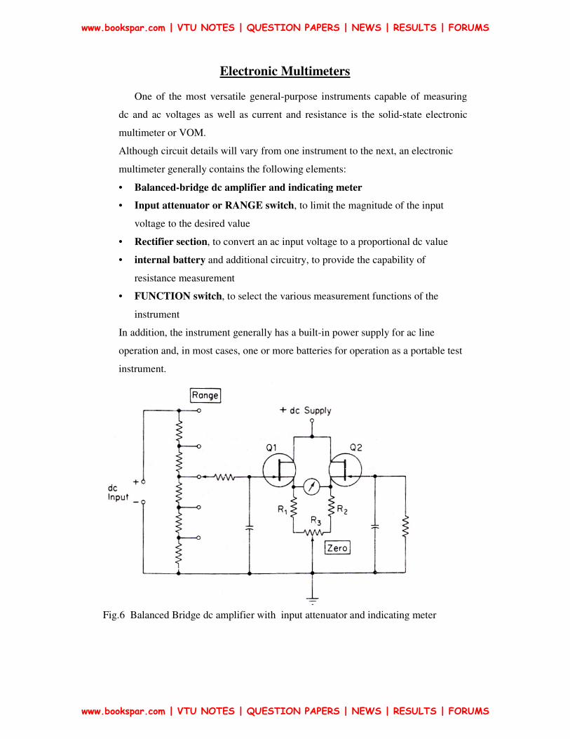
Fig.6 Balanced Bridge dc amplifier with input attenuator and indicating meter
www.bookspar.com | VTU NOTES | QUESTION PAPERS | NEWS | RESULTS | FORUMS
www.bookspar.com | VTU NOTES | QUESTION PAPERS | NEWS | RESULTS | FORUMS

Working of individual Components
Balanced Bridge DC amplifier
As shown in Fig. 6 the balanced-bridge dc amplifier uses FETs (BJTs can also
be used). The two FETs should be well matched for current gain to ensure thermal
stability of the circuit. The two FETs form the upper arms of a bridge circuit.
Source resistors R I and R2 , together with ZERO adjust resistor R3 , form the
lower bridge arms. The meter movement is connected between the source
terminals of the FETs, representing two opposite corners of the bridge. Without an
input signal, the gate terminals of the FETs are at ground potential and the
transistors operate under identical quiescent conditions. In this case, the bridge is
balanced and the meter indication is zero. However, small differences in the
operating characteristics of the transistors, and slight tolerance differences in the
various resistors, cause a certain amount of unbalance in the drain currents, and
the meter shows a small deflection from zero.
To return the meter to zero, the circuit is balanced by ZERO adjust control
R3 for a true null indication.
Output Indication
When a positive voltage is applied to the gate of input transistor Q1, its drain
current increases which causes the voltage at the source terminal to rise. The
resulting unbalance between the Ql and Q2 source voltages is indicated by the
meter movement, whose scale is calibrated to agree with the magnitude of the
applied input voltage.
Input Attenuator Or RANGE Switch
Typical input voltage attenuator for a VOM is shown in Fig.7. The RANGE
switch on the front of the panel of the VOM allows selection of the desired
voltage range. The maximum voltage that can be applied to the gate of Q1 is
determined by the operating range of FET (usually a few volts). The range of
input voltages can easily be extended by an input attenuator or RANGE switch,
as shown in Fig.7. The unknown dc input voltage is applied through a large
resistor in the probe body to a resistive voltage divider. Thus, with the RANGE
www.bookspar.com | VTU NOTES | QUESTION PAPERS | NEWS | RESULTS | FORUMS
www.bookspar.com | VTU NOTES | QUESTION PAPERS | NEWS | RESULTS | FORUMS

switch in the 3-V position as shown, the voltage at the gate of the input FET is
developed across 8 MΩ of the total resistance of 11.3 MΩ and the circuit is so
arranged that the meter deflects full scale when 3 V is applied to the tip of the
probe. With the RANGE switch in the 12-V position, the gate voltage is
developed across 2 MΩ of the total divider resistance of 11.3 MΩ and an input
voltage of 12 V is required to cause the same full-scale meter deflection.
Fig. 7
www.bookspar.com | VTU NOTES | QUESTION PAPERS | NEWS | RESULTS | FORUMS
www.bookspar.com | VTU NOTES | QUESTION PAPERS | NEWS | RESULTS | FORUMS

Resistance Ranges
When the function switch of the multimeter is placed in the OHMS position, the
unknown resistor is connected in series with an internal battery, and the meter
simply measures the voltage drop across the unknown. A typical circuit is shown
in Fig.8, where a separate divider network, used only for resistance measurements,
provides for a number of different resistance ranges. When unknown resistor Rx is
connected to the OHMS terminals of the multimeter, the 1.5-V battery supplies
current through one of the range resistors and the unknown resistor to ground.
Fig.8
Voltage drop Vx across Rx is applied to the input of the bridge amplifier and
causes a deflection on the meter. Since the voltage drop across Rx is directly
proportional to its resistance the meter scale can be calibrated in terms of
resistance which in an Electronic multimeter is from left to right (vice versa for
ordinary multimeter). i.e., High Rx => High Vx ( in ordinary multimeter High Rx
=> Low current I)
www.bookspar.com | VTU NOTES | QUESTION PAPERS | NEWS | RESULTS | FORUMS
www.bookspar.com | VTU NOTES | QUESTION PAPERS | NEWS | RESULTS | FORUMS

Digital Voltmeters
Digital voltmeters are essentially analog-to-digital converters with digital displays
to indicate the measured voltage. DVM displays measurements of ac or dc
voltages as discrete numerals instead of a pointer deflection on a continuous scale.
The development of ICs has lead to drastic reduction of the size, power
requirements and cost of DVM. Hence DVMs can actively compete with
conventional analog instruments, both in portability and price.
CONSIDERATIONS IN CHOOSING AN ANALOG VOLTMETER
The most appropriate instrument for a particular voltage measurement depends on
the performance required in a given situation. Some important considerations are
– Input Impedance
– Voltage Ranges
– Decibels
– Sensitivity Versus Bandwidth
– Battery Operation
Typical Operating And Performance Characteristics of DVMs
• Input range.. from ±1.000000 V to ±1,000.000 V, with automatic range
selection and overload indication
• Absolute accuracy.. as high as ±0.005 per cent of the reading
• Stability.` short-term, 0.002 per cent of the reading for a 24-hr period; long-
term, 0.008 per cent of the reading for a 6-month period
• Resolution.. 1 part in 106 (1µ V can be read on the 1-V input range)
• input characteristics.. input resistance typically 10 MΩ; input capacitance
typically 40 pF
• Calibration. internal calibration standard allows calibration independent of
the measuring circuit; derived from stabilized reference source
• Output signals. print command allows output to printer; BCD (binary-
coded-decimal) output for digital processing or recording
• Additional features may include additional circuitry to measure current,
resistance, and voltage ratios. Other physical variables may be measured by
using suitable transducers.
www.bookspar.com | VTU NOTES | QUESTION PAPERS | NEWS | RESULTS | FORUMS
www.bookspar.com | VTU NOTES | QUESTION PAPERS | NEWS | RESULTS | FORUMS

Classification of DVMs
1. Ramp-type DVM
2. Integrating DVM
3. Continuous-balance DVM
4. Successive-approximation DVM
Ramp-type DVM
Its Operating principle is based on the measurement of the time it takes for a linear
ramp voltage to rise from 0 V to the level of the input voltage, or to decrease from
the level of the input voltage to zero. This time interval is measured with an
electronic time-interval counter, and the count is displayed as a number of digits
on electronic indicating tubes.
Fig. 9 Block diagram of a ramp-type digital voltmeter
The working principle i.e., the Conversion from a voltage to a time interval is
illustrated by the waveform in Fig. 10
www.bookspar.com | VTU NOTES | QUESTION PAPERS | NEWS | RESULTS | FORUMS
www.bookspar.com | VTU NOTES | QUESTION PAPERS | NEWS | RESULTS | FORUMS
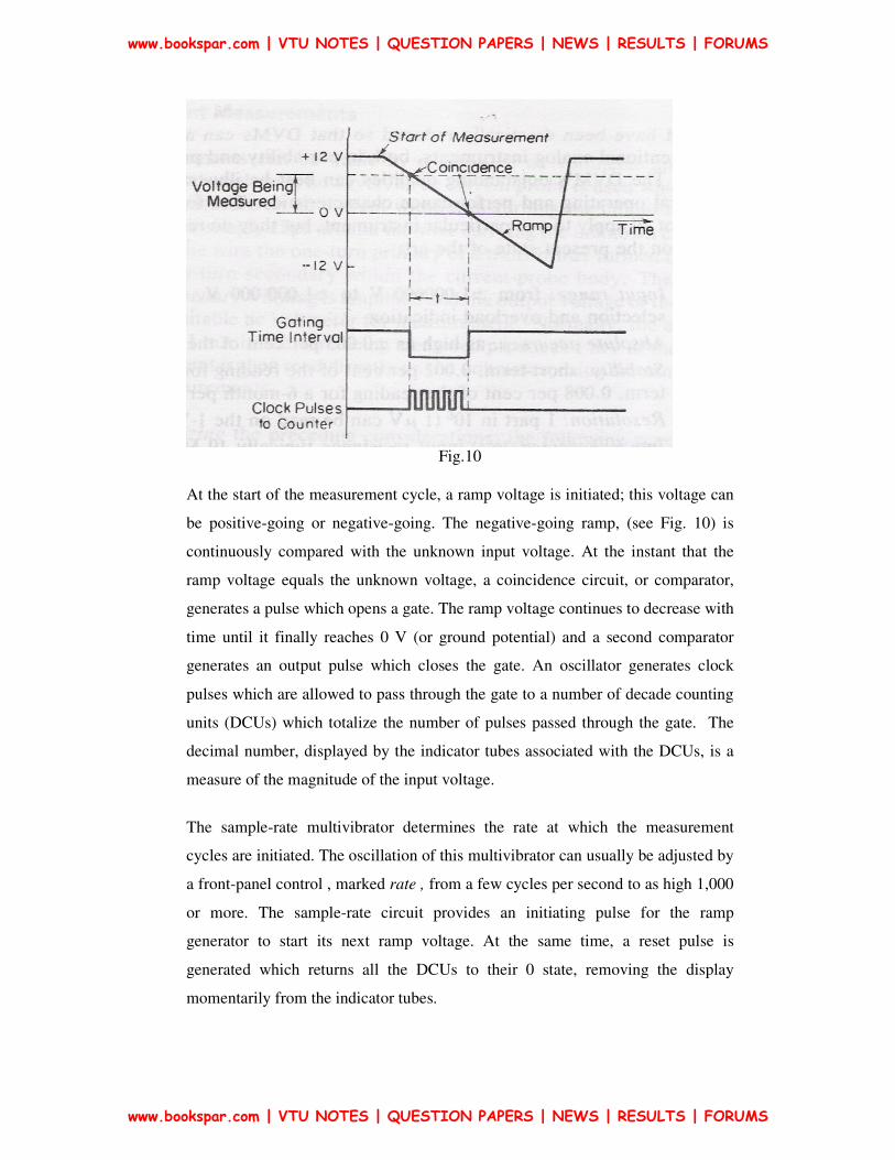
Fig.10
At the start of the measurement cycle, a ramp voltage is initiated; this voltage can
be positive-going or negative-going. The negative-going ramp, (see Fig. 10) is
continuously compared with the unknown input voltage. At the instant that the
ramp voltage equals the unknown voltage, a coincidence circuit, or comparator,
generates a pulse which opens a gate. The ramp voltage continues to decrease with
time until it finally reaches 0 V (or ground potential) and a second comparator
generates an output pulse which closes the gate. An oscillator generates clock
pulses which are allowed to pass through the gate to a number of decade counting
units (DCUs) which totalize the number of pulses passed through the gate. The
decimal number, displayed by the indicator tubes associated with the DCUs, is a
measure of the magnitude of the input voltage.
The sample-rate multivibrator determines the rate at which the measurement
cycles are initiated. The oscillation of this multivibrator can usually be adjusted by
a front-panel control , marked rate , from a few cycles per second to as high 1,000
or more. The sample-rate circuit provides an initiating pulse for the ramp
generator to start its next ramp voltage. At the same time, a reset pulse is
generated which returns all the DCUs to their 0 state, removing the display
momentarily from the indicator tubes.
www.bookspar.com | VTU NOTES | QUESTION PAPERS | NEWS | RESULTS | FORUMS
www.bookspar.com | VTU NOTES | QUESTION PAPERS | NEWS | RESULTS | FORUMS

Staircase-Ramp DVM
It is a variation of the ramp-type DVM but is simpler in overall design,
resulting in a moderately priced general-purpose instrument that can be used
in the laboratory, on production test-stands, in repair shops, and at inspection
stations. Stair case ramp DVM makes voltage measurements by comparing the
input voltage to an internally generated staircase-ramp voltage.
Fig. 11
It contains a 10-MΩ input attenuator, providing five input ranges from 100
mV to 1,000 V full scale. The dc amplifier with a fixed gain of 100, delivers 10 V
to the comparator at any of the full-scale voltage settings of the input
divider. The comparator senses coincidence between the amplified input voltage
and the staircase-ramp voltage which is generated as the measurement proceeds
through its cycle . A Clock (4.5 kHz oscillator) provides pulses to three DCUs
in cascade. The units counter provides a carry pulse to the tens decade at every
tenth input pulse. The tens decade counts the carry pulses from the units decade
and provides its own carry pulse after it has counted ten carry pulses. This carry
pulse is fed to the hundreds decade which provides a carry pulse to an over-
range circuit. The over range circuit causes a front panel indicator to light up,
warning the operator that the input capacity of the instrument has been
exceeded. The operator should then switch to the next higher setting on the input
attenuator.
Each decade counter unit is connected to a digital-to-analog (D/A) converter.
www.bookspar.com | VTU NOTES | QUESTION PAPERS | NEWS | RESULTS | FORUMS
www.bookspar.com | VTU NOTES | QUESTION PAPERS | NEWS | RESULTS | FORUMS
The outputs of the D/A converters are connected in parallel and provide an output
current proportional to the current count of the DCUs. The staircase amplifier
converts the D/A current into a staircase voltage which is applied to the
comparator. When the comparator senses coincidence of the input voltage and the
staircase voltage, it provides a trigger pulse to stop the oscillator. The current
content of the counter is then proportional to the magnitude of the input voltage.
The sample rate is controlled by a simple relaxation oscillator. This oscillator
triggers and resets the transfer amplifier at a rate of two samples per second. The
transfer amplifier provides a pulse that transfers the information stored in the
decade counters to the front panel display unit. The trailing edge of this
pulse triggers the reset amplifier which sets the three decade counters to zero
and initiates a new measurement cycle by starting the master oscillator or clock.
The display circuits store each reading until a new reading is completed,
eliminating any blinking or counting during the computation.
The ramp type of A/D converter requires a precision ramp to achieve accuracy.
Maintaining the quality of the ramp requires a precise, stable capacitor and
resistor in the integrator. In addition, the offset voltages and currents of the
operational amplifier used in the integrator are critical in the accurate ramp
generator. One method of reducing the dependence of the accuracy of the
conversion on the resistor, capacitor, and operational amplifier is to use a technique
called the dual-slope converter.
Dual-Slope Converter
In the dual-slope technique, an integrator is used to integrate an accurate
voltage reference for a fixed period of time. The same integrator is then used to
integrate with the reverse slope, the input voltage, and the time required to return
to the starting voltage is measured. The Order of integrations does not matter.
Consider the integration of the unknown first as shown in Fig. 12
www.bookspar.com | VTU NOTES | QUESTION PAPERS | NEWS | RESULTS | FORUMS
www.bookspar.com | VTU NOTES | QUESTION PAPERS | NEWS | RESULTS | FORUMS

Fig. 12
The output voltage Vout is given by
Where t - elapsed time from when the integration began. The above Equation also
assumes that the integrator capacitor started with no charge & thus the output of the
integrator started at zero volts.
If the integration were allowed to continue for a fixed period of time T1, the
output voltage would be
Notice that the integrator output has gone in the opposite polarity as the input.
That is, a positive input voltage produces a negative integrator output. If a reference
voltage Vref, were substituted for the input voltage Vx, as shown in Fig.13, the
integrator would begin to ramp toward zero at a rate of Vref/ RC assuming that the
Vref was of the opposite polarity as the unknown input voltage. The integrator for
this situation does not start at zero but at an output voltage of V1, and the output
voltage Vout is
www.bookspar.com | VTU NOTES | QUESTION PAPERS | NEWS | RESULTS | FORUMS
www.bookspar.com | VTU NOTES | QUESTION PAPERS | NEWS | RESULTS | FORUMS

Fig.13
Setting the output voltage of the integrator to zero and solving for Vx yields
where Tx is the time required to ramp down from the output level of V1 to zero volts.
Notice that the relationship between the reference voltage and the input voltage does
not include R or C of the integrator but only the relationship between the two times.
Because the relationship between the two times is a ratio, an accurate clock is not
required but only that the clock used for the timing be stable enough that the
frequency does not change appreciably from the up ramp to the down ramp.
Fig. 14
www.bookspar.com | VTU NOTES | QUESTION PAPERS | NEWS | RESULTS | FORUMS
www.bookspar.com | VTU NOTES | QUESTION PAPERS | NEWS | RESULTS | FORUMS
As the integrator responds to the average of the input, it is not necessary to
provide a sample and hold, as changes in the input voltage will not cause
significant errors. Although the integrator output will not be a linear ramp, the
integration will represent the end value obtained by a voltage equal to the average
of the unknown input voltage. Therefore, the dual-slope analog-to-digital
conversion will produce a value equal to the average of the unknown input.
The dual-slope type of A/D conversion is a very popular method for digital
voltmeter applications. When compared to other types of ADC techniques, the
dual-slope method is slow but is quite adequate for a digital voltmeter used for
laboratory measurements. For data acquisition applications, where a number of
measurements are required, faster techniques are recommended. Many
refinements have been made to the technique and many large-scale-integration
(LSI) chips are available to simplify the construction of DVMs.
When a dual-slope A/D converter is used for a DVM the counters may be
decade rather than binary and the segment and digit drivers may be contained in
the chip. When the converter is to interface to a microprocessor, and many high-
performance DVMs use microprocessors for data manipulation, the counters
employed are binary.
One significant enhancement made to the dual-slope converter is automatic
zero correction. As with any analog system, amplifier offset voltages, offset
currents, and bias currents can cause errors. In addition, in the dual-slope A/D
converter, the leakage current of the capacitor can cause errors in the integration
and consequentially, an error. These effects, in the dual-slope AID converter, will
manifest themselves as a reading of the DVM when no input voltage is present.
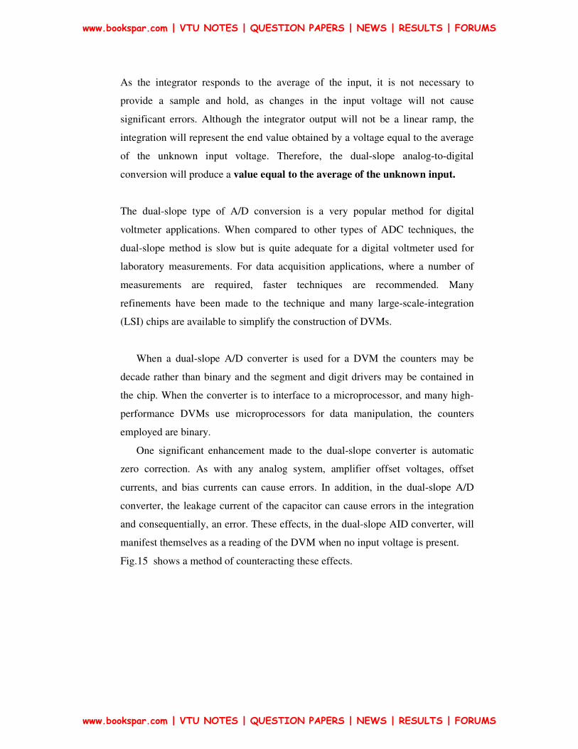
Fig.15 shows a method of counteracting these effects.
www.bookspar.com | VTU NOTES | QUESTION PAPERS | NEWS | RESULTS | FORUMS
www.bookspar.com | VTU NOTES | QUESTION PAPERS | NEWS | RESULTS | FORUMS
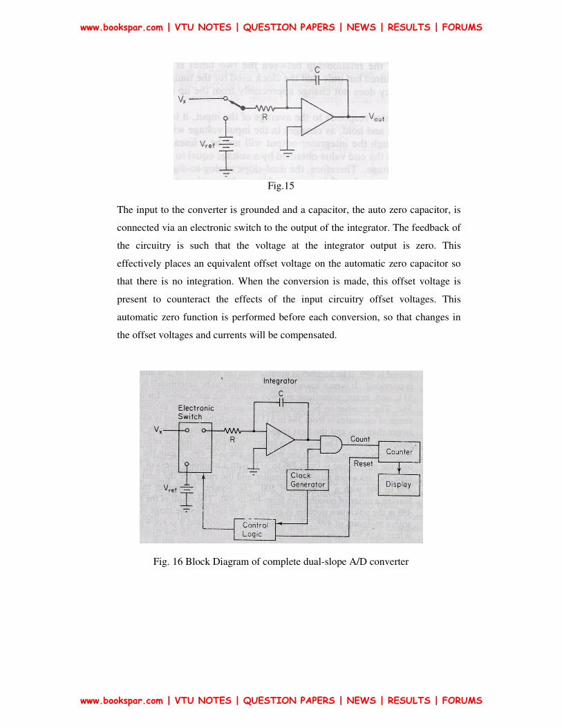
Fig.15
The input to the converter is grounded and a capacitor, the auto zero capacitor, is
connected via an electronic switch to the output of the integrator. The feedback of
the circuitry is such that the voltage at the integrator output is zero. This
effectively places an equivalent offset voltage on the automatic zero capacitor so
that there is no integration. When the conversion is made, this offset voltage is
present to counteract the effects of the input circuitry offset voltages. This
automatic zero function is performed before each conversion, so that changes in
the offset voltages and currents will be compensated.
Fig. 16 Block Diagram of complete dual-slope A/D converter
www.bookspar.com | VTU NOTES | QUESTION PAPERS | NEWS | RESULTS | FORUMS
www.bookspar.com | VTU NOTES | QUESTION PAPERS | NEWS | RESULTS | FORUMS
Successive-approximation DVM
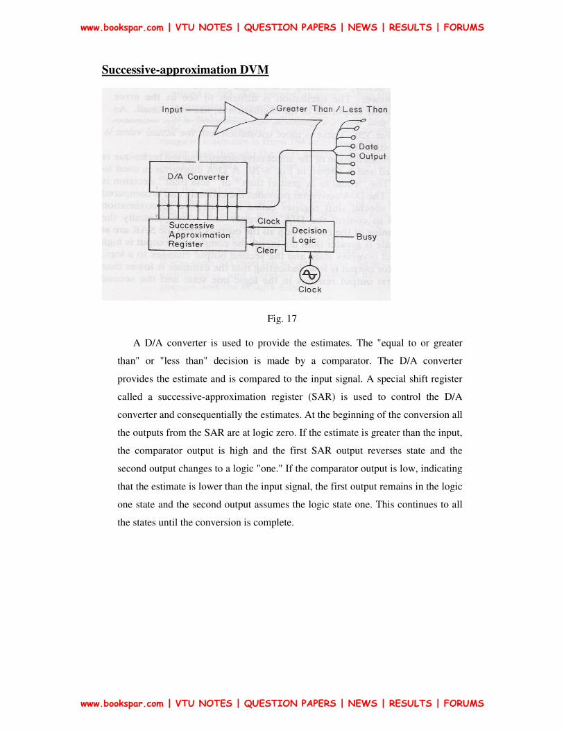
Fig. 17
A D/A converter is used to provide the estimates. The "equal to or greater
than" or "less than" decision is made by a comparator. The D/A converter
provides the estimate and is compared to the input signal. A special shift register
called a successive-approximation register (SAR) is used to control the D/A
converter and consequentially the estimates. At the beginning of the conversion all
the outputs from the SAR are at logic zero. If the estimate is greater than the input,
the comparator output is high and the first SAR output reverses state and the
second output changes to a logic "one." If the comparator output is low, indicating
that the estimate is lower than the input signal, the first output remains in the logic
one state and the second output assumes the logic state one. This continues to all
the states until the conversion is complete.
www.bookspar.com | VTU NOTES | QUESTION PAPERS | NEWS | RESULTS | FORUMS
www.bookspar.com | VTU NOTES | QUESTION PAPERS | NEWS | RESULTS | FORUMS

Q-Meter
The Q meter is an instrument designed to measure some of the electrical
properties of coils and capacitors. The operation of this useful laboratory
instrument is based on the characteristics of a series-resonant circuit, i.e., that the
voltage across the coil or the capacitor is equal to the applied voltage times the Q
of the circuit. If a fixed voltage is applied to the circuit, a voltmeter across the
capacitor can be calibrated to read Q directly.
Fig. 18 Basic Q-Meter Circuit
if E is maintained at a constant and known level, a voltmeter connected across the
capacitor can be calibrated directly in terms of the circuit Q as
Practical Q-meter Circuit
Fig. 19
www.bookspar.com | VTU NOTES | QUESTION PAPERS | NEWS | RESULTS | FORUMS
www.bookspar.com | VTU NOTES | QUESTION PAPERS | NEWS | RESULTS | FORUMS

The wide-range oscillator with a frequency range from 50 kHz to 50 MHz
delivers current to a low-value shunt resistance RsH. The value of this shunt is
very low, typically on the order of 0.02 Ω. It introduces almost no resistance into
the oscillatory circuit and it therefore represents a voltage source of magnitude E
with a very small (in most cases negligible) internal resistance. The voltage E
across the shunt, corresponding to E in Fig.19, is measured with a thermocouple
meter, marked “Multiply Q by”. The voltage across the variable capacitor,
corresponding to EC in Fig.19 , is measured with an electronic voltmeter whose
scale is calibrated directly in Q values.
To make a measurement, the unknown coil is connected to the test terminals
of the instrument, and the circuit is tuned to resonance either by setting the
oscillator to a given frequency and varying the internal resonating capacitor or by
presetting the capacitor to a desired value and adjusting the frequency of the
oscillator. The Q reading on the output meter must be multiplied by the index
setting of the "Multiply Q by" meter to obtain the actual Q value. The indicated Q
(which is the resonant reading on the “Circuit Q" meter) is called the circuit Q
because the losses of the resonating capacitor, voltmeter, and insertion resistor are
all included in the measuring circuit. The effective Q of the measured coil will be
somewhat greater than the indicated Q. This difference can generally be neglected
except in certain cases where the resistance of the coil is relatively small in
comparison with the value of the insertion resistor
The inductance of the coil can be calculated from the known values of freq f and
capacitance C as XL =XC & L = 1 / (2πf)2C
Measurement Methods
There are three methods for connecting unknown components to the test terminals of
a Q meter: direct, series, and parallel.
The type of component and its size determine the method of connection
Direct connection
Most coils can be connected directly across the test terminals, exactly as shown in the
basic Q-circuit of Fig.19. The circuit is resonated by adjusting either the oscillator
frequency or the resonating capacitor. The indicated Q is read directly from the
www.bookspar.com | VTU NOTES | QUESTION PAPERS | NEWS | RESULTS | FORUMS
www.bookspar.com | VTU NOTES | QUESTION PAPERS | NEWS | RESULTS | FORUMS

"Circuit Q" meter, modified by the setting of the "Multiply Q by" meter. When the
"Multiply Q by" meter is set at the unity mark, the “Circuit Q" meter reads the correct
value of Q directly.
Series connection
Low-impedance components, sub as low-value resistors, small coils, and large
capacitors, are measured in series with the measuring circuit. Fig.20 shows the
connections. The component to be measured here indicated by [Z], is placed in
series with a stable work coil across the test terminals. (The work coil is usually
supplied with the instrument)
Fig.20 Q-meter measurement of a low-impedance component in series connection.
Two measurements are made:
In the first measurement the unknown is short-circuited by a small shorting strap and
the circuit is resonated, establishing a reference condition. The values of the tuning
capacitor (C1) and the indicated Q (Q1) are noted.
In the second measurement the shorting strap is removed and the circuit is resonated,
giving a new value for the tuning capacitor (C2) and a change in the Q value from Q1
to Q2 .
www.bookspar.com | VTU NOTES | QUESTION PAPERS | NEWS | RESULTS | FORUMS
www.bookspar.com | VTU NOTES | QUESTION PAPERS | NEWS | RESULTS | FORUMS

For the second measurement, the reactance of the unknown can be expressed in terms
of the new value of the tuning capacitor (C2) and the in-circuit value of the inductor
(L). This yields
XS is inductive if C1 > C2 and capacitive if C1 < C2
The resistive component of the unknown impedance can be found in terms of
reactance XS and the indicated values of circuit Q, since
If Rs were purely resistive, in the tuning process C will not change, C1 = C2
If the unknown is a small inductor, the value of the inductance is found from Eq. and
is
Q of the coil is found as
www.bookspar.com | VTU NOTES | QUESTION PAPERS | NEWS | RESULTS | FORUMS
www.bookspar.com | VTU NOTES | QUESTION PAPERS | NEWS | RESULTS | FORUMS

Where Rs & Xs are
If the unknown where a large capacitor, Xs is used to find Cs value as
& its Q is as above
Parallel connection
High-impedance components, such as high-value resistors, certain inductors, and
small capacitors are connected them in parallel with the measuring circuit.
Fig.21 Circuit for Parallel Connection
Before the unknown is connected, the circuit is resonated, by using a suitable
work coil to establish reference values for Q and C (Q1 & C1 ). Next the
component under test is connected to the circuit, the capacitor is readjusted for
resonance, a new value for the tuning capacitance (C2) is obtained and a change in
the value of circuit Q (∆Q) from Q1 to Q2. At the initial resonance condition,
when the unknown is not yet connected into the circuit, the working coil (L) is
tuned by the capacitor (C1). Therefore
www.bookspar.com | VTU NOTES | QUESTION PAPERS | NEWS | RESULTS | FORUMS
www.bookspar.com | VTU NOTES | QUESTION PAPERS | NEWS | RESULTS | FORUMS

When the unknown impedance is connected into the circuit and the capacitor is tuned
for resonance, the reactance of the working coil (XL) equals the parallel reactances of
the tuning capacitor (Xc2) & the unknown (Xp)
)(
1 and inductive, isunknown If
21
2CC
LLX PPP−
==
ω
ω
If the unknown is capacitive, Xp = 1/ωCp and CP = C1 – C2
In a parallel resonant circuit the total resistance at resonance is equal to the
product of the circuit Q and the reactance of the coil. Therefore
The resistance (Rp) of the unknown impedance is found by using the conductances in
the circuit
• GT -- total conductance of the resonant circuit
• Gp -- conductance of the unknown impedance
• GL -- conductance of the working coil
GT = GP + GL
GP = GT – GL
www.bookspar.com | VTU NOTES | QUESTION PAPERS | NEWS | RESULTS | FORUMS
www.bookspar.com | VTU NOTES | QUESTION PAPERS | NEWS | RESULTS | FORUMS

Sources of Error
Distributed capacitance measurement
The most important factor affecting measurement accuracy is the distributed
capacitance or self capacitance of the measuring circuit. The presence of
distributed capacitance in a coil modifies the actual or effective Q and the
inductance of the coil. At the frequency at which the self-capacitance and the
inductance of the coil are resonant, the circuit exhibits a purely resistive
impedance. This characteristic may be used for measuring the distributed
capacitance as shown in Fig.22 .
Fig.22
Working: make two measurements at different frequencies. The coil under test is
connected directly to the test terminals of the Q meter, as shown in Fig.22. The
tuning capacitor is set to a high value, preferably to its maximum position, and the
circuit is resonated by adjusting the oscillator frequency. Resonance is indicated
by maximum deflection on the "Circuit Q" meter. The values of the tuning
capacitor ( C1) and the oscillator frequency (f1) are noted. The frequency is then
increased to twice its original value = 2f1 and the circuit is returned by adjusting
the resonating capacitor (C2).
The resonant frequency of an LC circuit is given by
At the initial resonance condition, the capacitance of the circuit equals C1 + Cd & the
resonant frequency equals
www.bookspar.com | VTU NOTES | QUESTION PAPERS | NEWS | RESULTS | FORUMS
www.bookspar.com | VTU NOTES | QUESTION PAPERS | NEWS | RESULTS | FORUMS

After the oscillator and the tuning capacitor are adjusted, the capacitance of the circuit
is C2 + Cd , and the resonant frequency equals
Solving for the distributed capacitance
www.bookspar.com | VTU NOTES | QUESTION PAPERS | NEWS | RESULTS | FORUMS
www.bookspar.com | VTU NOTES | QUESTION PAPERS | NEWS | RESULTS | FORUMS


![Inductance, Capacitance, and Mutual Inductancefaculty.weber.edu/snaik/ECE1270/Ch6.pdfInductance, Capacitance, and Mutual Inductance Assessment Problems AP 6.1 [a] ig = 8e−300t −](https://img.pdfslide.net/doc/110x75/5f0246127e708231d4037222/inductance-capacitance-and-mutual-inductance-capacitance-and-mutual-inductance.jpg)