Embed Size (px)
Citation preview

LCI ELECTRONIC LEVELINGCLASS A LEVELING SYSTEM
OPERATION AND SERVICE MANUAL
SYSTEM
WARNING!FAILURE TO ACT IN ACCORDANCE WITH THE FOLLOWING MAY RESULT IN SERIOUS PERSONAL INJURY OR DEATH.
THE USE OF THE LIPPERT ELECTRONIC LEVELING SYSTEM TO SUPPORT THE COACH FOR ANY REASON OTHER THANWHICH IT IS INTENDED IS PROHIBITED BY LIPPERT’S LIMITED WARRANTY. THE LIPPERT LEVELING SYSTEM IS DESIGNEDAS A “LEVELING” SYSTEM ONLY AND SHOULD NOT BE USED TO PROVIDE SERVICE FOR ANY REASON UNDER THE COACHSUCH AS CHANGING TIRES OR SERVICING THE LEVELING SYSTEM.
LIPPERT COMPONENTS, INC. RECOMMENDS THAT A TRAINED PROFESSIONAL BE EMPLOYED TO CHANGE THE TIRE ON THECOACH. ANY ATTEMPTS TO CHANGE TIRES OR PERFORM OTHER SERVICE WHILE COACH IS SUPPORTED BY THE LIPPERTLEVELING SYSTEM COULD RESULT IN DAMAGE TO THE MOTOR HOME AND/OR CAUSE SERIOUS INJURY OR DEATH.
BE SURE TO PARK THE COACH ON SOLID, LEVEL GROUND.
CLEAR ALL JACK LANDING LOCATIONS OF DEBRIS AND OBSTRUCTIONS. LOCATIONS SHOULD ALSO BE FREE OF DEPRESSIONS.
WHEN PARKING THE COACH ON EXTREMELY SOFT SURFACES, UTILIZE LOAD DISTRIBUTION PADS UNDER EACH JACK.
PEOPLE AND PETS SHOULD BE CLEAR OF COACH WHILE OPERATING LEVELING SYSTEM.
BE SURE TO KEEP HANDS AND OTHER BODY PARTS CLEAR OF FLUID LEAKS. OIL LEAKS IN THE LIPPERT LEVELING SYSTEM MAY BE UNDER HIGH PRESSURE AND CAN CAUSE SERIOUS SKIN PENETRATING INJURIES.
NEVER LIFT THE COACH COMPLETELY OFF THE GROUND. LIFTING THE COACH SO THE WHEELS ARE NOT TOUCHING GROUND WILL CREATE AN UNSTABLE AND UNSAFE CONDITION.
PRIOR TO OPERATIONThe leveling system shall only be operated under the following conditions:1. The coach is parked on a reasonably level surface.2. The coach “PARKING BRAKE” is engaged.3. The coach transmission should be in the neutral or park position4. Be sure all persons, pets and property are clear of the coach while Lippert Leveling System is in operation.
SYSTEM DESCRIPTIONPlease read and study the operating manual before you operate the leveling system.
The Lippert Electronic Leveling System is an electric/hydraulic system. A 12V DC electric motor drives a hydraulic pump thatmoves fluid through a system of hoses, fittings and jacks to level and stabilize the coach.
The Lippert Electronic Leveling System is totally integrated into the chassis of the coach at the manufacturer.
There are no serviceable parts within the electric motor. If the motor fails, Pump Unit must be replaced.
Disassembly of the Pump Assembly voids the warranty.
Mechanical portions of the Lippert Electronic Leveling System are replaceable. Contact Lippert Components, Inc. to obtainreplacement parts.
COMPONENT DESCRIPTIONThe Lippert Electronic Leveling System consists of the following major components:
Lippert jacks are rated at a lifting capacity appropriate for your coach. Each jack has a 9" diameter (63.5 square inch) shoe on a ballswivel for maximum surface contact on all surfaces. (12” dia. - 113 sq. in. shoe also available).
Each jack is powered from a central 12VDC motor/pump assembly, which also includes the hydraulic oil reservoir tank, control valvemanifold, and solenoid valves.
The Lippert Electronic Leveling System is controlled electronically from the driver’s seat of the coach. The control panel ismounted in the dash. The system can be operated in a manual mode or a fully automatic mode.
FLUID RECOMMENDATIONThe Lippert Electronic Leveling System is pre-filled, primed and ready to operate direct from the manufacturer. Type “A” AutomaticTransmission Fluid (ATF) is utilized and will work. ATF with Dexron III or Mercon 5 or a blend of both is recommended by LippertComponents, Inc. In colder temperatures (less than 10° F) the jacks may extend and retract slowly due to the fluid’s molecularnature. For cold weather operation, fluid specially formulated for low temperatures may be desirable. Please consult factory beforeusing any other fluids.
LIPPERTCOMPONENTS, INC.

PREVENTATIVE MAINTENANCE PROCEDURES1. Change fluid in RESERVOIR ONLY every 36 months.
a) Check fluid only when jacks are fully retracted.b) Always fill the reservoir with the jacks in the fully retracted position. Filling reservoir when jacks are extended will cause reservoir to overflow into its compartment when jacks are retracted.c) When checking fluid level, fluid should be within ¼” of fill spout lip.
2. Check the fluid level every month.3. Inspect and clean all Pump Unit electrical connections every 12 months. If corrosion is evident, spray unit with WD-40 or equivalent
4. Remove dirt and road debris from jacks as needed.
WARNING!Your coach should be supported at both front and rear axles with jack stands before working underneath.
Failure to do so may result in personal injury or death.
5. If jacks are down for extended periods, it is recommended to spray exposed leveling jack rods with a silicone lubricant every seven days for protection. If your coach is located in a salty environment, it is recommended to spray the rods every 2 to 3 days.
CAPACITY - 22,000 lb.STROKE - 16 in.H - 20 1/2 in.D - 3 3/8 in.12” SHOE-STANDARD
D D
D
H H
H
115842 115841
Fig.1a Fig.1b
Fig.1c
CAPACITY - 12,000 lb.STROKE - 15 in.H - 19 1/2 in.D - 2 3/8 in.9” SHOE-STANDARD12” SHOE-OPTIONAL
CAPACITY - 7,000 lb.STROKE - 13.75 in.H - 18 1/4 in.D - 2 3/8 in.A - 2 1/2 in.9” SHOE-STANDARD12” SHOE-OPTIONAL
CAPACITY - 7,000 lb.STROKE - 13.75 in.H - 18 1/4 in.D - 2 3/8 in.A - 5 3/4 in.9” SHOE-STANDARD12” SHOE-OPTIONAL
D
H
Fig.1d
117179
A A
113314
NOTE - OEM to supply attachment brackets for leveling jacks.

Fig. 2
Fig. 3
Manual Override
(under cap)12V DC Motor
Hydraulic Valve Manifold
Valve CoilValve -(Coil and Valve Capenclose stem of valve.)
Motor Solenoid - Part # - 161394
Pressure Switch
Return Fitting
Quick DisconnectFlush & Fill
Quick Disconnect Flush & FillValve/Coil - Part # - 138417
12V DC Power (+)
- 5/16” Nut
Ground Power (-)
- 1/4” Nut
Plastic Cap
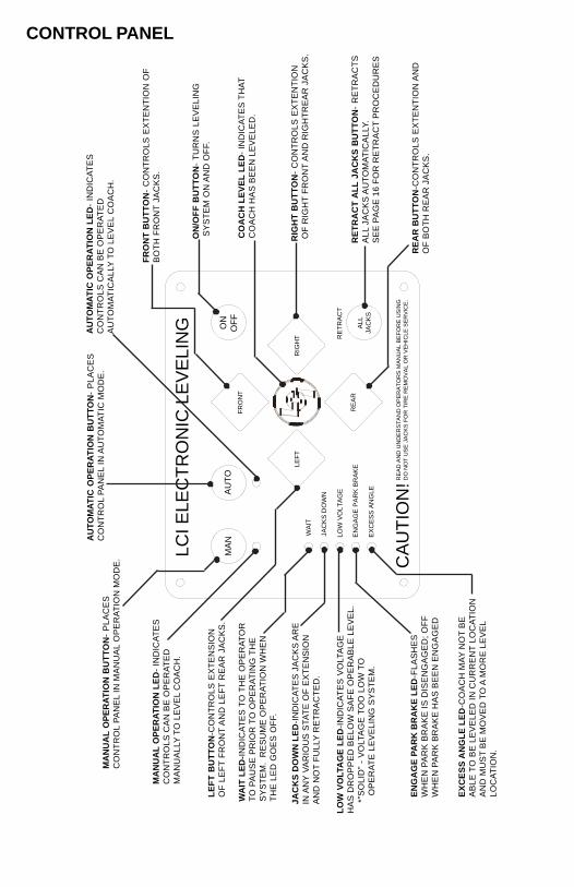
CONTROLS
FEATURES· Automatic extension of jacks from full retract position (with automatic ground detection).· Automatic leveling of jacks.· Manual leveling of jacks· Automatic retraction of jacks (with automatic full retract detection).· Air bag suspension features (configurable on/off).· Emergency retract/User alarm mode (jacks not retracted and park brake disengaged).· Automatic jack error detection and error mode.· Configuration mode for Air features.· Configurations mode for Leveling Zero Point.- Remote operation.
SYSTEM WIRING REQUIREMENTS· Battery power (2 ga. SAE J1127. Type SGX).· Battery ground (2 ga. SAE J1127. Type SGX).· Logic power (switched via ignition)· Power brake signal (open=park brake disengaged, GND=park brake engaged).· 4-wire harness connecting Controller to Touch Panel.· Jacks status input-Switched to GND Jacks not all up – switch closed to ground Jacks all up – switch open
AIR AND AUXILIARY FEATURES(When Applicable)
System has the option to control external Air and Auxiliary features.
When enabled, the feature works according to the following logic:· Air bag pressure automatically lowered when starting the auto or manual sequence to maximize lift of jacks.· An Auxiliary mode activated when starting an auto retract sequence to fill air bags.· Auxiliary is active when jacks are all retracted and park brake is disengaged to fill airbags.
LEVEL ZERO POINT CALIBRATION
Before auto-leveling features are available, the Level Zero point must be set. This is the point to which the system will returnwhen an auto leveling cycle is initiated.To set the zero point (controller module must be fully secured in production intent location), first run a manual leveling sequenceto get the vehicle to the desired level point. Then activate the Level Zero point configuration mode.
This mode is enabled by performing the following sequence:1. Turn panel off. Then turn panel on.2. Perform the following:
-Press the FRONT switch 5 times.-Press the REAR switch 5 times.
3. At this point all LED outputs will blink, and the buzzer will be off.4. You are now in IDLE mode ready to set Zero Point.5. With a carpenter’s level, manually level the coach. This will give the leveling controls the reference point for the Zero Point Configuration.6. When coach is completely leveled manually press the RETRACT ALL switch 3 times to set the zero point.
For DIESEL UNITS with Airbag Suspensions ONLY:NOTE - You may also enter zero mode per above at anytime the system is in IDLE mode. The user then has control to extendany pair of jacks while in zero mode in order to position the vehicle properly prior to programming.
AIR AND AUXILIARY FEATURE CONFIGURATION
For DIESEL UNITS with Airbag Suspensions ONLY:· Feature is entered ONLY after zero mode programming.· At this point the WAIT LED will blink for 20 seconds. You are now in Air/Auxiliary Feature Configuration mode.
To enable Air Auxiliary features, perform the following:· Press the RETRACT ALL switch 3 times· User must do this within 20 seconds of entering this mode.
To disable Air features, perform the following:· Do nothing· After 20 seconds, module will exit mode with features disabled.
ERROR MODEIf any problem is detected with the jacks, the system will enter error mode. Error mode may be recognized by the blinking ofLEFT, CENTER LCI and RIGHT LEDs.
The following errors are detected by this system:Jack over current/short circuit.Jack under current/ open circuit.Jack extending too long (ground not detected after 2 min.).Jack retracting too long (fully retracted not detected after 2 min.).Out of stroke detection during auto cycle (if enabled).
The user must respond by pressing ON/OFF switch, which resets operation.
All normal features are disabled in Error mode.
If panel loses communication with the controller for more than 5 seconds, the panel will blink the JACKS DOWN, PARK BRAKEand ON/OFF (if included) LEDs.

ICICL
USER ALARM MODEIf the alarm system detects that the park brake has been disengaged while at least one jack is not fully retracted and the sensorvalue changes in any axis more than a predefined amount, the panel will signal this error to the user.
When in alarm mode, all LEDs will flash and the buzzer will beep. The Status LEDs will show the system status.
The system performs an automatic retract.
No other features are available in this mode.
MISCELLANEOUS· The system will automatically shut down after 4 minutes of no operation.· Auto leveling cycle cannot be started until all jacks are fully retracted. Make sure jacks are retracted before attempting to
auto level (unit will perform full retract automatically if jacks are not down on the request of an auto cycle).· System will refuse any operation when a low voltage condition is present.· System will automatically alarm and retract if park brake is disengaged and jacks are not retracted with any change in
sensor readings. In alarm mode, the only available feature is to retract all jacks.· Please note the Wait LED shows the status of Air/ Auxiliary features.
NOTE - The LEDs blink differently when in special controller modes (error, alarm, and configuration). Learning how to recognizethese modes is important. Excess slope LED blinks whenever the Y axis (vehicle length) is over 5o from programmed level point.
LOW VOLTAGE SIGNAL If LOW VOLTAGE light is on solid, it is an indication of a charging system problem. Turn ignition OFF and then back ON to reset system. If LOW VOLTAGE light persists, test battery under load at battery and at the motor solenoid on the pump unit. Check all power and ground connections at the battery, alternator and chassis.
“LATCHED OUT” WARNING
FLASHING
LATCHED ERROR mode is “WAIT,” “JACKS DOWN,” “PARK BRAKE,” “EXCESS SLOPE” AND “LOW VOLTAGE” lights flashing.
1. Battery voltage below 10.0V DC.2. Retract time over 67 seconds in auto retract.3. This is the only LATCHED ERROR MODE.4. All revisions prior to “G” controllers treat this error as regular ERROR mode.
To RESET, push all 4 diamond-shaped jack buttons at the same time.
OPERATION
SELECTING A SITEWhen the coach is parked on an excessive slope the leveling requirements may exceed the jack lift stroke capability. If the coach isparked on an excessive slope, the coach should be moved to a more level surface before the leveling system is deployed.
AUTOMATIC LEVELING PROCEDURENOTE - REFER TO FIG. 4 FOR QUESTIONS REGARDING LOCATION AND FUNCTIONS OF THE LIPPERT COMPONENTS, INC. ELECTRONIC LEVELING SYSTEM.NOTE - Coach must be running for LCI Electronic Leveling System to operate.1. Push ON/OFF button on Control Panel. The system is now operational and the electronic level lights will become active.2. Check to see that the Control Pad ENGAGE PARK BRAKE light is not flashing.NOTE - Engage Parking Brake if ENGAGE PARK BRAKE light is flashing.3. Push the AUTO button to begin the automatic leveling cycle.
CONTROL PANEL
RE
AD
AN
D U
ND
ER
ST
AN
D O
PE
RA
TO
RS
MA
NU
AL
BE
FO
RE
US
ING
DO
NO
T U
SE
JA
CK
S F
OR
TIR
E R
EM
OV
AL
OR
VE
HIC
LE S
ER
VIC
E.
LEF
T
LCI E
LEC
TR
ON
IC L
EV
ELI
NG
EX
CE
SS
AN
GL
E
CA
UT
ION
!
EN
GA
GE
PA
RK
BR
AK
E
LO
W V
OL
TA
GE
JAC
KS
DO
WN
WA
IT
MA
NA
UT
O
RE
AR
AL
LJA
CK
S
RE
TR
AC
T
RIG
HT
FR
ON
T
ON
OF
F
EX
CE
SS
AN
GL
E L
ED
-CO
AC
H M
AY
NO
T B
EA
BL
E T
O B
E L
EV
EL
ED
IN
CU
RR
EN
T L
OC
AT
ION
AN
D M
US
T B
E M
OV
ED
TO
A M
OR
E L
EV
EL
LO
CA
TIO
N.
EN
GA
GE
PA
RK
BR
AK
E L
ED
-FL
AS
HE
SW
HE
N P
AR
K B
RA
KE
IS
DIS
EN
GA
GE
D;
OF
FW
HE
N P
AR
K B
RA
KE
HA
S B
EE
N E
NG
AG
ED
LO
W V
OLT
AG
E L
ED
-IN
DIC
AT
ES
VO
LTA
GE
HA
S D
RO
PP
ED
BE
LO
W S
AF
E O
PE
RA
BL
E L
EV
EL
.
*”
SO
LID
” -
VO
LTA
GE
TO
O L
OW
TO
O
PE
RA
TE
LE
VE
LIN
G S
YS
TE
M.
JA
CK
S D
OW
N L
ED
-IN
DIC
AT
ES
JA
CK
S A
RE
IN A
NY
VA
RIO
US
STA
TE
OF
EX
TE
NS
ION
AN
D N
OT
FU
LLY
RE
TR
AC
TE
D.
WA
IT L
ED
-IN
DIC
AT
ES
TO
TH
E O
PE
RA
TO
RT
O P
AU
SE
PR
IOR
TO
OP
ER
AT
ING
TH
ES
YS
TE
M.
RE
SU
ME
OP
ER
AT
ION
WH
EN
TH
E L
ED
GO
ES
OF
F.
LE
FT
BU
TT
ON
-CO
NT
RO
LS
EX
TE
NS
ION
OF
LE
FT
FR
ON
T A
ND
LE
FT
RE
AR
JA
CK
S.
MA
NU
AL
OP
ER
AT
ION
LE
D-
IND
ICA
TE
SC
ON
TR
OL
S C
AN
BE
OP
ER
AT
ED
MA
NU
AL
LY T
O L
EV
EL
CO
AC
H.
MA
NU
AL
OP
ER
AT
ION
BU
TT
ON
- P
LA
CE
SC
ON
TR
OL
PA
NE
L IN
MA
NU
AL
OP
ER
AT
ION
MO
DE
.
AU
TO
MA
TIC
OP
ER
AT
ION
BU
TT
ON
- P
LA
CE
SC
ON
TR
OL
PA
NE
L IN
AU
TO
MA
TIC
MO
DE
.A
UT
OM
AT
IC O
PE
RA
TIO
N L
ED
- IN
DIC
AT
ES
CO
NT
RO
LS
CA
N B
E O
PE
RA
TE
DA
UT
OM
AT
ICA
LLY
TO
LE
VE
L C
OA
CH
.
FR
ON
T B
UT
TO
N-
CO
NT
RO
LS
EX
TE
NT
ION
OF
BO
TH
FR
ON
T J
AC
KS
.
ON
/OF
F B
UT
TO
N-
TU
RN
S L
EV
EL
ING
SY
ST
EM
ON
AN
D O
FF.
CO
AC
H L
EV
EL
LE
D-
IND
ICA
TE
S T
HA
TC
OA
CH
HA
S B
EE
N L
EV
EL
ED
.
RIG
HT
BU
TT
ON
- C
ON
TR
OL
S E
XT
EN
TIO
N O
F R
IGH
T F
RO
NT
AN
D R
IGH
TR
EA
R J
AC
KS
.
RE
TR
AC
T A
LL
JA
CK
S B
UT
TO
N-
RE
TR
AC
TS
AL
L JA
CK
S A
UT
OM
AT
ICA
LLY
.S
EE
PA
GE
16
FO
R R
ET
RA
CT
PR
OC
ED
UR
ES
RE
AR
BU
TT
ON
-CO
NT
RO
LS
EX
TE
NT
ION
AN
DO
F B
OT
H R
EA
R J
AC
KS
.

MANUAL LEVELING PROCEDURESNOTE - When leveling your coach, the coach should be leveled from FRONT TO REAR first (step 2-4). When the coach is level from FRONT TO REAR, then level the coach from LEFT TO RIGHT (step 5).NOTE - Coach must be running for LCI Electronic Leveling System to operate.1. Push ON/OFF button on control panel. The system is now operational and the ON/OFF light will be lit.2. Push and hold MAN button for 5 seconds.3. Push FRONT button until jacks contact the ground and lift the front of the coach 1-2 inches.4. Push REAR button until jacks contact the ground and lift rear of coach. Keep button depressed until bubble is centered.5. Push LEFT or RIGHT button; if bubble is towards left of coach, push RIGHT button; if bubble is towards right of coach push LEFT button. Keep button depressed until bubble is centered in vial.NOTE - The right and left jacks are used to level the coach side to side. Pushing the LEFT button on the control panel will extend both left jacks. Pushing the RIGHT button on the control panel will extend both right jacks. Jacks always work in pairs, both front jacks; both right side jacks, etc.6. Repeat steps 2 through 5 if needed.7. Turn power off to leveling system by pushing ON/OFF button.8. Visually inspect all jacks to ensure all shoes are touching ground. Should one of the rear jack shoes not be touching the ground, press the corresponding LEFT or RIGHT rear jack buttons to lower the corresponding jack to the ground.
WARNING!NEVER LIFT ALL THE WHEELS OFF THE GROUND TO LEVEL THE COACH!Lifting all wheels of the ground may result in serious personal injury or death.
JACK RETRACT PROCEDURES1. Energize the system by pushing ON/OFF button on control panel. The ON/OFF light will be lit.2. Push the RETRACT ALL JACKS button. All the jacks will start to retract and returns to the full retract position. When all jacks return to full retract position the JACKS DOWN light will go out.NOTE - If you wish to stop the jacks from retracting, turn the system off and back on again by pushing the on/off pad twice. You can
then re-level the coach by following steps 1-5 again.3. When the JACKS DOWN light goes out, push the ON/OFF button on the Control Panel to deenergize the system. After a brief visual inspection around the coach to verify the jacks are fully retracted, you may proceed to travel.NOTE - When in the MANUAL mode, if the RETRACT button is pushed the jacks will only retract as long as the RETRACT buttonis depressed. In AUTOMATIC mode, the RETRACT button need only be pressed once and released for the jacks to fully retract.
WARNING!After starting the automatic leveling cycle it is very important that you do not move around in the coach until the unit is leveland the green LCI logo light illuminates in the center of the touch pad. Failure to remain still during the leveling cycle could
have an affect on the performance of the leveling system.
4. If further adjustments are necessary, simply push and hold the MAN button for approximately 5 seconds until the light under this button is illuminated. Push the appropriate leg button to override the system and level the coach to your liking.
WARNING!NEVER LIFT ALL THE WHEELS OFF THE GROUND TO LEVEL THE COACH!
Lifting all wheels of the ground may resultin serious personal injury or death.
5. Push ON/OFF button to de-energize the system.

MANUAL OVERRIDE - POWER SYSTEMThe Lippert Electronic Leveling System can be run with auxiliary power devices like electric drills, ratchet wrenches or cordlessscrewdrivers. In the event of electrical or system failure, this manual method of extending and retracting the jacks can be used. Astandard handheld drill is all that is required. See the instructions below.
Fig. 6
1. Remove plastic cap. (See Fig 6).2. Disconnect power cables on the motor.3. Using a 1/2” socket, insert into auxiliary drive device, i.e. cordless or power drill
4. Insert 1/2” socket onto coupler found under plastic capl, Fig. 7.5. Run drill forward or clockwise to extend jacks and in reverse or counterclockwise to retract jacks.
Fig. 7
MANUAL OVERRIDE - JACKSIn the event that the jacks will not extend or retract, the valves can be manually overridden. By using a 5/32” allen wrench (Pre-2006model year, see update below) to turn the manual override clockwise on the valve, see Fig. 5a, the leveling jacks can then be extendedor retracted. Remember to turn the manual override completely counterclockwise, see Fig. 5b, until it will no longer turn, to close thevalve after the jacks have been completely extended or retracted.
Fig. 5a
Clockwise for manual override
Fig. 5b
Counter-clockwise for normal operation
2 2

AUTOMATIC SAFETY SHUTOFFIf the control panel is left on and inactive for four minutes it will shut off automatically. To reset the system the coach ignition must beturned off, then back on and the ON/OFF button must again be pushed.
DRIVE AWAY PROTECTION SYSTEMIf the ignition is in the “RUN” position, jacks are down, and the operator releases the parking brake, all indicator lights will flash and thealarm beeper will activate. The system will then automatically retract the jacks until the jacks are fully retracted or the operator resetsthe parking brake.
“JACKS DOWN” ALARMThe Lippert Electronic Leveling System is designed to sound an alarm and illuminate the control panel in the event of two (2) possiblescenarios:
1. A “RETRACT” hose leaks.2. The pressure holding the jacks in the retracted position falls to a approximately 1500 psi to sound the alarm.
If the alarm sounds and the control panel illuminates and flash while driving the vehicle;3. Immediately find an area to safely pull the vehicle off of the roadway.4. Set the PARKING BRAKE.5. Inspect all jacks hoses and check valve for leaks.6. If no leaks are observed;
a. Turn control panel “ON.”b. Push “RETRACT ALL JACKS” button.c. Wait until “JACKS DOWN” light and alarm are off.d. Inspect jacks. If jacks are retracted and no leaks are observed, vehicle can be driven.
If system is leaking or alarm does not subside after applying the above procedure, disconnect wires from pressure switch and proceedimmediately to a service center. For prolonged travel to the service center, be sure to stop and check the disposition of the levelingjacks every so often to make sure they are not extending.
FRONT JACK EXTEND - 3-POINTFRONT ROADSIDE EXTEND - 4-POINT
FRONT CURBSIDE EXTEND - 4-POINTNOT USED IN 3-POINT
REAR ROADSIDE EXTEND
REAR CURBSIDE EXTEND
FRONT RETRACT
REAR RETRACT
FRONT CROSSOVER
REAR CROSSOVER
LEVELING HOSE COLOR CHART

PLUMBING DIAGRAMFig. 8
1.
Ho
ses
will
va
ry in
len
gth
by
coa
ch m
od
el.
M
ea
sure
ho
se a
nd
co
nsu
lt L
CI
Se
rvic
e.
Ho
se S
pe
cs.
30
00
p.s
.i.;
½”
in.
I.D
.2
. C
urb
sid
e F
ron
t -
Bla
ck H
ose
- P
UR
PL
E L
ab
el &
Wir
e3
. R
oa
dsi
de
Fro
nt
- B
lack
Ho
se -
GR
EE
N L
ab
el &
Wir
e4
. C
urb
sid
e R
ea
r -
Bla
ck H
ose
- R
ED
La
be
l & W
ire
5.
Ro
ad
sid
e R
ea
r -
Bla
ck H
ose
- B
LU
E L
ab
el &
Wir
e6
. R
etu
rn -
Ora
ng
e H
ose
7.
PS
I S
witc
h -
Ye
llow
Wir
e in
to B
lue
PS
I W
ire
12
3
5
4
6
7

WIRING DIAGRAMFig. 9
23
456
789
IC ICL
4-PIN PHONE HARNESS
12
-PIN
WIR
E H
AR
NE
SS
1 –
WH
ITE
(CH
AS
SIS
PO
WE
R)
2 –
BL
AC
K W
/WH
ITE
(PU
MP
SO
LE
NO
ID)
3 –
RE
D(C
UR
BS
IDE
RE
AR
VA
LVE
)4
– G
RE
EN
(R
OA
DS
IDE
FR
ON
T V
ALV
E)
5 –
YE
LL
OW
(P
SI
SW
ITC
H)
6 –
BL
UE
(R
OA
DS
IDE
RE
AR
VA
LVE
)7
– B
RO
WN
(G
RO
UN
D)
8 –
PU
RP
LE
(C
UR
BS
IDE
FR
ON
T V
ALV
E)
9 –
GR
EY
(P
UM
P S
OL
EN
OID
)1
0 -
AU
X11
- A
UX
12
- A
UX
15A
FU
SE
PL
UG
S IN
TO
PU
MP
HA
RN
ES
SP
RO
VID
ED
BY
LC
I
DIR
EC
TIO
NA
L V
ALV
E
1
RE
D -
IG
NIT
ION
WH
ITE
- P
AR
K B
RA
KE
;G
RO
UN
D
BLA
CK
- A
IRB
AG
DU
MP
YE
LLO
W-
AIR
BA
G F
ILL

TROUBLESHOOTING CHARTSYSTEM WILL NOT TURN ON AND ON/OFF INDICATOR LIGHT DOES NOT ILLUMINATE
PROBABLE CAUSE CORRECTIVE ACTIONCoach Ignition not in RUN position Turn ignition to RUN positionParking brake not set Set parking brakeControls have been on for more than four Turn ignition OFF and then back ON minutes and have timed out.
CONTROL PAD TURNS ON BUT TURNS OFF WHEN LEG BUTTON IS PUSHEDPROBABLE CAUSE CORRECTIVE ACTIONLow voltage on battery Start coach to charge battery
CONTROL PAD TURNS ON, COACH WILL NOT AUTO-LEVEL, JACKS DOWN LIGHT IS ON, JACKS ARERETRACTEDPROBABLE CAUSE CORRECTIVE ACTIONLow fluid level Check fluid level in reservoir, if fluid is low
add fluid to FILL TO HERE line on reservoirIf JACKS DOWN light remains on call LippertService.
JACKS WILL NOT EXTEND TO GROUND, PUMP IS RUNNINGPROBABLE CAUSE CORRECTIVE ACTIONLittle or no fluid in reservoir Fill reservoir with DEXRON III ATF, See pg. 1Leg valve is inoperative Clean, repair or replaceElectronic signal is lost between control Trace wires for voltage drop or loss of signaland leg valves Repair or replace necessary wires or replace
control pad
ANY ONE OR TWO JACKS WILL NOT RETRACTPROBABLE CAUSE CORRECTIVE ACTIONHose damaged or unconnected Replace with new hose or reconnect hoseReturn valve inoperative Replace inoperative return valveElectronic signal is lost between control Attempt to retract jacks in MANUAL mode. and solenoid If successful, replace control pad; if not, test
for voltage drop between control pad and legvalve repair bad wiring or replace defectiveboard or valve.
“JACKS DOWN” LIGHT DOES NOT GO OUT WHEN ALL JACKS ARE RETRACTEDPROBABLE CAUSE CORRECTIVE ACTIONLow fluid level Fill reservoir to proper level with ATF, See pg. 1Retract pressure switch inoperable Check connection or replace
ALARM SOUNDS AND “JACKS DOWN” LIGHT STARTS FLASHING WHILE TRAVELING ACKS ARE FULLY RETRACTED
PROBABLE CAUSE CORRECTIVE ACTIONLow fluid level Fill reservoir to proper level with ATF, See pg. 1Retract pressure switch inoperable Check connection or replace
JACK BLEEDS DOWN AFTER BEING EXTENDEDPROBABLE CAUSE CORRECTIVE ACTIONValve Manual Override open Close override, See pg. 7
CONTROL PAD POWERS UP; “LOW VOLTAGE” LIGHT FLASHESPROBABLE CAUSE CORRECTIVE ACTIONEngine not running Start coach engine
“LOW VOLTAGE” LIGHT ON SOLIDPROBABLE CAUSE CORRECTIVE ACTIONCharging system faulty Turn key OFF; then, back ON again to reset
Check power and ground connections onbattery, alternator and chassis
NO POWER TO CONTROL PADPROBABLE CAUSE CORRECTIVE ACTIONTripped circuit breaker ResetIgnition not ON Turn ON
www.lci1.com Toll free - (866) 524-7821LIPPERTCOMPONENTS, INC. SERVICE & WARRANTY