Embed Size (px)
Citation preview

Electronic Measurement Solutions
PressureLevelTemperature Transmitters Transducers Switches Indicators

NOSHOK is an ISO 9001:2008 registered company.
NOSHOK is a member and actively supports:
At NOSHOK, we pride ourselves on being innovators in the industry by continually offering the latest technology and measurement solutions, and providing the best customer support in the marketplace.
Established in 1967, NOSHOK was one of the fi rst companies to offer liquid fi lled pressure gauges. We also took a bold step by backing our quality gauges with an extended 3-year warranty. That unwavering standard of quality has endured for over 45 years, and as we have expanded our product offering we continue to provide industry-leading warranties. NOSHOK also leads the industry as one of the fi rst companies to offer corrosion-resistant zinc nickel plating standard on our carbon steel valves.
We have the capacity to put together special requirements which are so often hard to fi nd. If you do not fi nd what you need in this catalog, chances are we can still put a solution together.
NOSHOK is committed to providing excellence on every level. Thank you for choosing NOSHOK products.
Jeff N. ScottPresident
NOSHOK Corporate HeadquartersYour Single Source Instrumentation Company
3
WARRANTY INFORMATION
Industrial Pressure & Level Transmitters & TransducersNOSHOK’S Three Year Warranty applies to the following series: 100, 200, 612, 613, 615/616, 640, 660 and 800 Series Transmitters & Transducers
OEM Transmitters & TransducersNOSHOK’s Three Year Warranty applies to the following series: 300, 360, and 650 Series Transmitters & Transducers
Hazardous Location Pressure & Level Transmitters & TransducersNOSHOK’S Three Year Warranty applies to the following series: 619/620, 621/622, 623/624, 625/626 and 627 Series Transmitters & Transducers
Temperature TransmittersNOSHOK’S Three Year Warranty applies to the following series: 800 and 850 Series Transmitters & Switches
Sanitary Pressure Transmitters & TransducersNOSHOK’S Three Year Warranty applies to the following series: 11 and 21 Sanitary Transmitters
Digital Pressure GaugesNOSHOK’S Three Year Warranty applies to the following series: 1000 Digital Gauges
Pressure & Temperature SwitchesNOSHOK’S Three Year Warranty applies to the following series: 500, 800, 810 and 850 Series Electronic Switch Products
NOSHOK’S One Year Warranty applies to the following series: 100, 200, 300 and 400 Series Mechanical Switch Products
NOSHOK guarantees all products to be free from defects in material and workmanship, to remain within catalogued accuracy specifi cations, and to operate within the catalogued performance specifi cations. These products must be operated within the catalogued environmental and application parameters. Determination of failure will be made by NOSHOK, Inc.’s equipment and personnel or a certifi ed test facility specializing in this type of evaluation.
In keeping with and for purposes of product and/or manufacturing process improvements, NOSHOK, Inc. reserves the right to make design changes without prior notice.
4
WARRANTY INFORMATION
T A B L E O F C O N T E N T S
Transmitters & Transducers, Digital Pressure Gauges & Indicators, Pressure & Temperature Switches .............................................................3
Current Output: 100 SERIES ......................................................................................................................................................................................................... 6-7 Voltage Output: 200 SERIES ....................................................................................................................................................................................................... 8-9 Submersible Level: 612 SERIES ..................................................................................................................................................................................................... 10-11 Cage-Protected Submersible Level: 613 SERIES ..................................................................................................................................................................................................... 12-13 High Accuracy:: 615/616 SERIES .................................................................................................................................................................................................. 14-15 Precision: 640 SERIES ...................................................................................................................................................................................................... 16-17 Micro-sized: 660 SERIES ......................................................................................................................................................................................................18-19 Electronic Indicating Pressure Transmitter/Switch: 800/810 SERIES .................................................................................................................................................................................................62-63
Compact: 300 SERIES .....................................................................................................................................................................................................20-21 High Volume:: 650 SERIES .....................................................................................................................................................................................................22-23
ATEX-Approved Explosion-Proof: 619/620 SERIES .................................................................................................................................................................................................24-25 Explosion-Proof: 621/622 SERIES ................................................................................................................................................................................................26-27 Non-Incendive: 623/624 SERIES ................................................................................................................................................................................................28-29 Intrinsically Safe: 625/626 SERIES ................................................................................................................................................................................................30-31 Intrinsically Safe Submersible Level: 627 SERIES ......................................................................................................................................................................................................32-33
Platinum Resistance: 800 SERIES .................................................................................................................................................................................................... 34-35
INDUSTRIAL PRESSURE & LEVEL TRANSMITTERS & TRANSDUCERS
OEM TRANSMITTERS & TRANSDUCERS
HAZARDOUS LOCATION PRESSURE & LEVEL TRANSMITTERS & TRANSDUCERS
TEMPERATURE TRANSMITTERS

5
Electronic Indicating Transmitter/Switch: 850 SERIES .....................................................................................................................................................................................................62-63
ASME-BPE Sanitary Clamp: 11 SERIES ......................................................................................................................................................................................................... 36-37 Homogenizer: 21 SERIES ........................................................................................................................................................................................................ 38-39
Digital Gauge:1000 SERIES .......................................................................................................................................................................................................40-41
Mechanical Miniature Low Pressure: 100 SERIES .........................................................................................................................................................................................................42-43Mechanical Compact: 200 SERIES ........................................................................................................................................................................................................ 44-45Mechanical: 300 SERIES ....................................................................................................................................................................................................... 46-47 Mechanical Heavy-Duty:400 SERIES ........................................................................................................................................................................................................ 48-49Electronic Mag-Switch::500 SERIES .........................................................................................................................................................................................................50-51Electronic Indicating Pressure Transmitter/Switch:800/810 SERIES ...................................................................................................................................................................................................52-53Electronic Indicating Temperature Transmitter/Switch: 850 SERIES ..................................................................................................................................................................................................... 54-55 Reference Guide.............................................................................................................................................................................................. 56-62Frequently Asked Questions ...............................................................................................................................................................................63Transmitters/Transducers, Wiring Diagrams & Electrical Connections .................................................................................................. 64-65
PRESSURE & TEMPERATURE SWITCHES
SANITARY PRESSURE TRANSMITTERS & TRANSDUCERS
T A B L E O F C O N T E N T S
DIGITAL PRESSURE GAUGES
TEMPERATURE TRANSMITTERS
100 100 SERIES
6
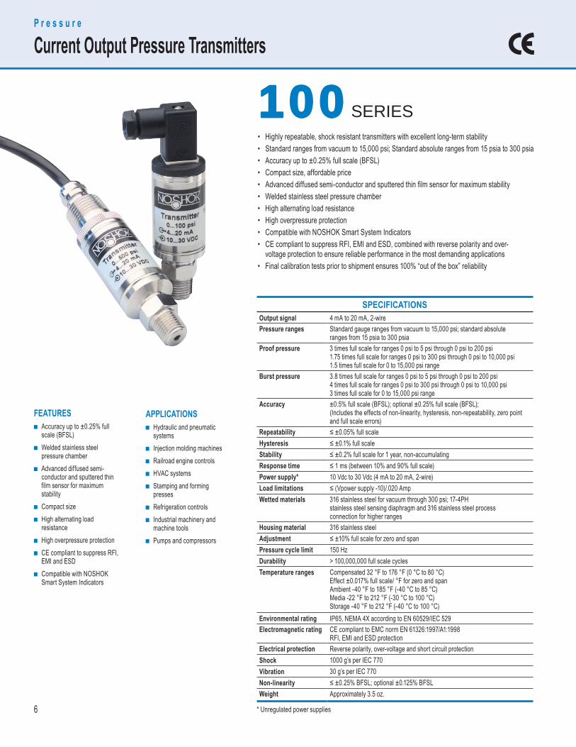
SPECIFICATIONS Output signal 4 mA to 20 mA, 2-wirePressure ranges Standard gauge ranges from vacuum to 15,000 psi; standard absolute
ranges from 15 psia to 300 psiaProof pressure 3 times full scale for ranges 0 psi to 5 psi through 0 psi to 200 psi
1.75 times full scale for ranges 0 psi to 300 psi through 0 psi to 10,000 psi1.5 times full scale for 0 to 15,000 psi range
Burst pressure 3.8 times full scale for ranges 0 psi to 5 psi through 0 psi to 200 psi 4 times full scale for ranges 0 psi to 300 psi through 0 psi to 10,000 psi 3 times full scale for 0 to 15,000 psi range
Accuracy ±0.5% full scale (BFSL); optional ±0.25% full scale (BFSL);(Includes the effects of non-linearity, hysteresis, non-repeatability, zero pointand full scale errors)
Repeatability ≤ ±0.05% full scaleHysteresis ≤ ±0.1% full scaleStability ≤ ±0.2% full scale for 1 year, non-accumulatingResponse time ≤ 1 ms (between 10% and 90% full scale)Power supply* 10 Vdc to 30 Vdc (4 mA to 20 mA, 2-wire)Load limitations ≤ (Vpower supply -10)/.020 AmpWetted materials 316 stainless steel for vacuum through 300 psi; 17-4PH
stainless steel sensing diaphragm and 316 stainless steel processconnection for higher ranges
Housing material 316 stainless steelAdjustment ≤ ±10% full scale for zero and spanPressure cycle limit 150 HzDurability > 100,000,000 full scale cyclesTemperature ranges Compensated 32 °F to 176 °F (0 °C to 80 °C)
Effect ±0.017% full scale/ °F for zero and spanAmbient -40 °F to 185 °F (-40 °C to 85 °C)Media -22 °F to 212 °F (-30 °C to 100 °C)Storage -40 °F to 212 °F (-40 °C to 100 °C)
Environmental rating IP65, NEMA 4X according to EN 60529/IEC 529Electromagnetic rating CE compliant to EMC norm EN 61326:1997/A1:1998
RFI, EMI and ESD protectionElectrical protection Reverse polarity, over-voltage and short circuit protectionShock 1000 g’s per IEC 770Vibration 30 g’s per IEC 770Non-linearity ≤ ±0.25% BFSL; optional ±0.125% BFSLWeight Approximately 3.5 oz.
APPLICATIONS ■ Hydraulic and pneumatic
systems ■ Injection molding machines ■ Railroad engine controls ■ HVAC systems ■ Stamping and forming
presses ■ Refrigeration controls ■ Industrial machinery and
machine tools ■ Pumps and compressors
FEATURES ■ Accuracy up to ±0.25% full
scale (BFSL) ■ Welded stainless steel
pressure chamber ■ Advanced diffused semi-
conductor and sputtered thin film sensor for maximum stability
■ Compact size ■ High alternating load
resistance ■ High overpressure protection ■ CE compliant to suppress RFI,
EMI and ESD ■ Compatible with NOSHOK
Smart System Indicators
P r e s s u r e
Current Output Pressure Transmitters
• Highly repeatable, shock resistant transmitters with excellent long-term stability• Standard ranges from vacuum to 15,000 psi; Standard absolute ranges from 15 psia to 300 psia• Accuracy up to ±0.25% full scale (BFSL)• Compact size, affordable price• Advanced diffused semi-conductor and sputtered thin fi lm sensor for maximum stability• Welded stainless steel pressure chamber• High alternating load resistance• High overpressure protection• Compatible with NOSHOK Smart System Indicators• CE compliant to suppress RFI, EMI and ESD, combined with reverse polarity and over- voltage protection to ensure reliable performance in the most demanding applications• Final calibration tests prior to shipment ensures 100% “out of the box” reliability
* Unregulated power supplies
7
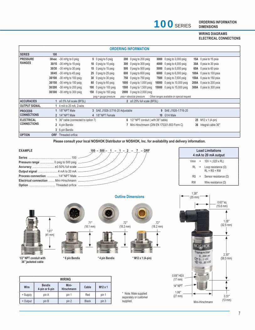
100 SERIES ORDERING INFORMATIONDIMENSIONS
WIRING DIAGRAMSELECTRICAL CONNECTIONS
Outline Dimensions
1.61"(41 mm)
1/2" NPT conduit with 36" jacketed cable
.71"(18.1 mm)
.72"(18.2 mm)
.72"(18.2 mm)
* 6 pin Bendix * 4 pin Bendix * M12 x 1 (4-pin)
* Note: Mate supplied separately or customer supplied.
WIRING
Wire Bendix4-pin or 6-pin
Mini- Hirschmann Cable M12 x 1
+ Supply pin A pin 1 Red pin 1
+ Output pin B pin 2 Black pin 3
1.38"(35 mm)
0.63" sq(15.8 mm)
1.28"(32.5 mm)
2.30"(58.5 mm)
0.51"(13 mm)
1.06"(27 mm)
14" NPT
0.69" HEX(17 mm)
Mini-Hirschmann
Load Limitations 4 mA to 20 mA output
Vmin = 10V + (.020 x RL)
RL = Loop resistance (Ω)RL = RS + RW
RS = Sensor resistance (Ω)
RW Wire resistance (Ω)
100 – 500 – 1 – 1 – 2 – 7 – ORF EXAMPLE
Series ........................................................ 100Pressure range .................. 0 psig to 500 psigAccuracy .............................±0.50% full scaleOutput signal .......................... 4 mA to 20 mAProcess connection ...............1/4″ NPT MaleElectrical connection ........ Mini-HirschmannOption ................................... Threaded orifice
ORDERING INFORMATIONSERIES 100 PRESSURE RANGES
30vac -30 inHg to 0 psig 5 0 psig to 5 psig 200 0 psig to 200 psig 3000 0 psig to 3,000 psig 15A 0 psia to 15 psia 30/15 -30 inHg to 15 psig 10 0 psig to 10 psig 300 0 psig to 300 psig 4000 0 psig to 4,000 psig 30A 0 psia to 30 psia 30/30 -30 inHg to 30 psig 15 0 psig to 15 psig 500 0 psig to 500 psig 5000 0 psig to 5,000 psig 60A 0 psia to 60 psia 30/45 -30 inHg to 45 psig 25 0 psig to 25 psig 600 0 psig to 600 psig 6000 0 psig to 6,000 psig 100A 0 psia to 100 psia
30/100 -30 inHg to 100 psig 30 0 psig to 30 psig 750 0 psig to 750 psig 7500 0 psig to 7,500 psig 150A 0 psia to 150 psia 30/150 -30 inHg to 150 psig 60 0 psig to 60 psig 1000 0 psig to 1,000 psig 10000 0 psig to 10,000 psig 200A 0 psia to 200 psia30/200 -30 inHg to 200 psig 100 0 psig to 100 psig 1500 0 psig to 1,500 psig 15000 0 psig to 15,000 psig 300A 0 psia to 300 psia30/300 -30 inHg to 300 psig 150 0 psig to 150 psig 2000 0 psig to 2,000 psig
psig = gauge pressure psia = absolute pressure Other ranges available on special request ACCURACIES 1 ±0.5% full scale (BFSL) 2 ±0.25% full scale (BFSL)OUTPUT SIGNAL 1 4 mA to 20 mA, 2-wirePROCESSCONNECTIONS
1 1/8″ NPT Male 3 SAE J1926-3:7/16-20 Adjustable 9 SAE J1926-1:7/16-202 1/4″ NPT Male 4 1/8″ NPT Female 10 G1/4 Male
ELECTRICALCONNECTIONS
1 36″ cable (connected to option 7) 6 1/2″ NPT conduit ( with 36″ cable) 25 M12 x 1 (4-pin)2 4-pin Bendix 7 Mini-Hirschmann (DIN EN 175301-803 Form C) 36 Integral cable 36″3 6-pin Bendix
OPTION ORF Threaded orifice
Please consult your local NOSHOK Distributor or NOSHOK, Inc. for availability and delivery information.

8
P r e s s u r e
Current Output Pressure Transmitters
APPLICATIONS ■ Hydraulic and pneumatic
systems ■ Injection molding machines ■ Railroad engine controls ■ HVAC systems ■ Stamping and forming
presses ■ Refrigeration controls ■ Industrial machinery and
machine tools ■ Pumps and compressors
FEATURES ■ Accuracy up to ±0.25% full
scale (BFSL) ■ Welded stainless steel
pressure chamber ■ Advanced diffused semi-
conductor and sputtered thin film sensor for maximum stability
■ Compact size ■ High alternating load
resistance ■ High overpressure protection ■ CE compliant to suppress RFI,
EMI and ESD ■ Compatible with NOSHOK
Smart System Indicators
SPECIFICATIONS Output signals 0 Vdc to 5 Vdc, 3-wire; 0 Vdc to 10 Vdc, 3-wire; 1 Vdc to 5 Vdc, 3-wire;
1 Vdc to 6 Vdc, 3-wire; 1 Vdc to 11 Vdc, 3-wirePressure ranges Standard gauge ranges from vacuum to 15,000 psi; Standard absolute
ranges from 15 psia to 300 psiaProof pressure 3 times full scale for ranges 0 psi to 5 psi through 0 psi to 200 psi
1.75 times full scale for ranges 0 psi to 300 psi through 0 psi to 10000 psi1.5 times full scale for 0 psi to 15,000 psi range
Burst pressure 3.8 times full scale for ranges 0 psi to 5 psi through 0 psi to 200 psi4 times full scale for ranges 0 psi to 300 psi through 0 psi to 10,000 psi3 times full scale for 0 psi to 15,000 psi range
Accuracy ±0.5% full scale (BFSL); optional ±0.25% full scale (BFSL); (Includes the effects of non-linearity, hysteresis, non-repeatability, zero point and full scale errors)
Repeatability ≤ ±0.05% full scaleHysteresis ≤ ±0.1% full scaleStability ≤ ±0.2% full scale per year, non-accumulatingResponse time ≤ 1 ms (between 10% and 90% full scale)Power supply* 10 Vdc to 30 Vdc (0 Vdc to 5 Vdc, 3-wire)
10 Vdc to 30 Vdc (1 Vdc to 5 Vdc, 3-wire)10 Vdc to 30 Vdc (1 Vdc to 6 Vdc, 3-wire)14 Vdc to 30 Vdc (0 Vdc to 10 Vdc, 3-wire) 14 Vdc to 30 Vdc (1 Vdc to 11 Vdc, 3-wire)
Load limitations ≥ 5,000 for 0 Vdc to 5 Vdc, 1 Vdc to 5 Vdc, and 1 Vdc to 6 Vdc outputs;≥10,000 for 0 Vdc to 10 Vdc and 1 Vdc to 11 Vdc outputs. Current consumption 8 mA
Wetted materials 316 stainless steel for vacuum through 300 psi; 17-4PH stainless steel sensing diaphragm and 316 stainless steel pressure connection for higher ranges
Housing material 316 stainless steelAdjustment ±10% full scale for zero and spanPressure cycle limit 150 HzDurability > 100,000,000 full scale cyclesTemperature ranges Compensated 32 °F to 176 °F (0 °C to 80 °C)
Effect ±0.017% full scale/ °F for zero and spanAmbient -40 °F to 185 °F (-40 °C to 85 °C)Media -22 °F to 212 °F (-30 °C to 100 °C)Storage -40 °F to 212 °F (-40 °C to 100 °C)
Environmental rating I P65, NEMA 4X according to EN 60529/IEC 529Electromagnetic rating CE compliant to EMC norm EN61326: 1997/A1: 1998 RFI, EMI and ESD protectionElectrical protection Reverse polarity, over-voltage and short circuit protectionShock 1,000 g’s per IEC 770Vibration 30 g’s per IEC 770Weight Approximately 3.5 oz.
• Highly repeatable, shock resistant transducers with excellent long-term stability• Standard ranges from vacuum to 15,000 psi; Standard absolute ranges from 15 psia to 300 psia• Accuracy up to ±0.25% full scale (BFSL)• Compact size, affordable price• Advanced diffused semi-conductor and sputtered thin fi lm sensor for maximum stability• Welded stainless steel pressure chamber• High alternating load resistance• High overpressure protection• Compatible with NOSHOK Smart System Indicators• CE compliant to suppress RFI, EMI and ESD, combined with reverse polarity and over- voltage protection to ensure reliable performance in the most demanding applications• Final calibration tests prior to shipment ensures 100% “out of the box” reliability
200 200 SERIES
P r e s s u r e
Voltage Output Pressure Transducers
* Unregulated power supplies
9
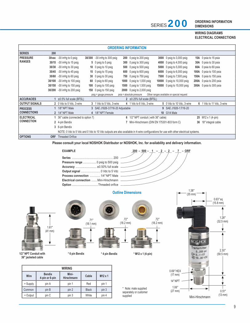
ORDERING INFORMATIONDIMENSIONS
WIRING DIAGRAMSELECTRICAL CONNECTIONS
Outline Dimensions
SERIES 200
200 – 500 – 1 – 2 – 2 – 7 – ORF EXAMPLE
Series ....................................................... 200Pressure range ..................0 psig to 500 psigAccuracy ............................ ±0.50% full scaleOutput signal .......................... 0 Vdc to 5 VdcProcess connection .............. 1/4″ NPT MaleElectrical connection ........Mini-HirschmannOption ...................................Threaded orifice
1.61"(41 mm)
1/2" NPT Conduit with 36" jacketed cable
.71"(18.1 mm)
.72"(18.2 mm)
.72"(18.2 mm)
* 6 pin Bendix * 4 pin Bendix * M12 x 1 (4-pin)
* Note: mate supplied separately or customer supplied
WIRING
Wire Bendix4-pin or 6-pin
Mini- Hirschmann Cable M12 x 1
+ Supply pin A pin 1 Red pin 1
Common pin B pin 2 Black pin 3+ Output pin C pin 3 White pin 4
1.38"(35 mm)
0.63" sq(15.8 mm)
1.28"(32.5 mm)
2.30"(58.5 mm)
0.51"(13 mm)
1.06"(27 mm)
14" NPT
0.69" HEX(17 mm)
Mini-Hirschmann
ORDERING INFORMATIONSERIES 200 PRESSURE RANGES
30vac -30 inHg to 0 psig 30/300 -30 inHg to 300 psig 200 0 psig to 200 psig 3000 0 psig to 3,000 psig 15A 0 psia to 15 psia 30/15 -30 inHg to 15 psig 5 0 psig to 5 psig 300 0 psig to 300 psig 4000 0 psig to 4,000 psig 30A 0 psia to 30 psia 30/30 -30 inHg to 30 psig 10 0 psig to 10 psig 500 0 psig to 500 psig 5000 0 psig to 5,000 psig 60A 0 psia to 60 psia 30/45 -30 inHg to 45 psig 15 0 psig to 15 psig 600 0 psig to 600 psig 6000 0 psig to 6,000 psig 100A 0 psia to 100 psia 30/60 -30 inHg to 60 psig 30 0 psig to 30 psig 750 0 psig to 750 psig 7500 0 psig to 7,500 psig 150A 0 psia to 150 psia
30/100 -30 inHg to 100 psig 60 0 psig to 60 psig 1000 0 psig to 1,000 psig 10000 0 psig to 10,000 psig 200A 0 psia to 200 psia30/150 -30 inHg to 150 psig 100 0 psig to 100 psig 1500 0 psig to 1,500 psig 15000 0 psig to 15,000 psig 300A 0 psia to 300 psia30/200 -30 inHg to 200 psig 150 0 psig to 150 psig 2000 0 psig to 2,000 psig
psig = gauge pressure psia = absolute pressure Other ranges available on special request ACCURACIES 1 ±0.5% full scale (BFSL) 2 ±0.25% full scale (BFSL)OUTPUT SIGNALS 2 0 Vdc to 5 Vdc, 3-wire 3 1 Vdc to 5 Vdc, 3-wire 4 1 Vdc to 6 Vdc, 3-wire 5 0 Vdc to 10 Vdc, 3-wire 6 1 Vdc to 11 Vdc, 3-wirePROCESSCONNECTIONS
1 1/8″ NPT Male 3 SAE J1926-3:7/16-20 Adjustable 9 SAE J1926-1:7/16-202 1/4″ NPT Male 4 1/8″ NPT Female 10 G1/4 Male
ELECTRICALCONNECTION
1 36″ cable (connected to option 7) 6 1/2″ NPT conduit ( with 36″ cable) 25 M12 x 1 (4-pin)2 4-pin Bendix 7 Mini-Hirschmann (DIN EN 175301-803 form C) 36 18″ integral cable3 6-pin Bendix
NOTE: 0 Vdc to 5 Vdc and 0 Vdc to 10 Vdc outputs are also available in 4-wire configurations for use with other electrical systems.OPTIONS ORF Threaded Orifice
Please consult your local NOSHOK Distributor or NOSHOK, Inc. for availability and delivery information.
10
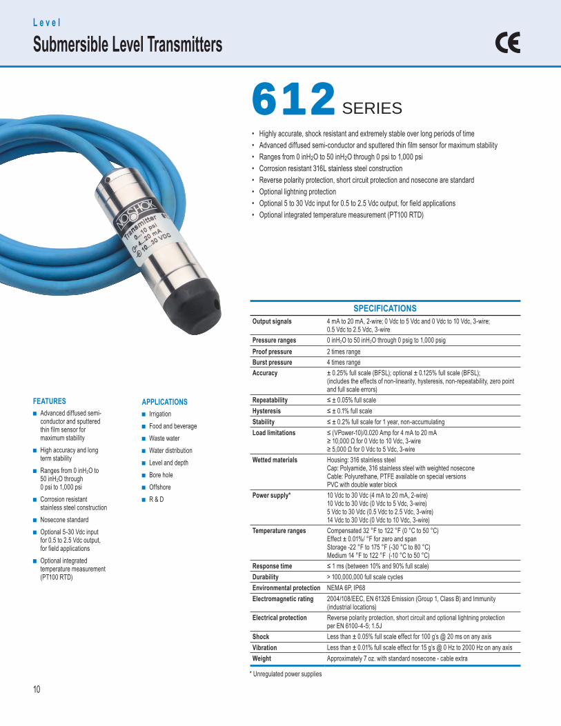
APPLICATIONS ■ Irrigation ■ Food and beverage ■ Waste water ■ Water distribution ■ Level and depth ■ Bore hole ■ Offshore ■ R & D
FEATURES ■ Advanced diffused semi-
conductor and sputtered thin film sensor for maximum stability
■ High accuracy and long term stability
■ Ranges from 0 inH2O to 50 inH2O through 0 psi to 1,000 psi
■ Corrosion resistant stainless steel construction
■ Nosecone standard ■ Optional 5-30 Vdc input
for 0.5 to 2.5 Vdc output, for field applications
■ Optional integrated temperature measurement (PT100 RTD)
SPECIFICATIONS Output signals 4 mA to 20 mA, 2-wire; 0 Vdc to 5 Vdc and 0 Vdc to 10 Vdc, 3-wire;
0.5 Vdc to 2.5 Vdc, 3-wirePressure ranges 0 inH2O to 50 inH2O through 0 psig to 1,000 psigProof pressure 2 times rangeBurst pressure 4 times rangeAccuracy ± 0.25% full scale (BFSL); optional ± 0.125% full scale (BFSL);
(includes the effects of non-linearity, hysteresis, non-repeatability, zero pointand full scale errors)
Repeatability ≤ ± 0.05% full scaleHysteresis ≤ ± 0.1% full scaleStability ≤ ± 0.2% full scale for 1 year, non-accumulatingLoad limitations ≤ (VPower-10)/0.020 Amp for 4 mA to 20 mA
≥ 10,000 Ω for 0 Vdc to 10 Vdc, 3-wire≥ 5,000 Ω for 0 Vdc to 5 Vdc, 3-wire
Wetted materials Housing: 316 stainless steelCap: Polyamide, 316 stainless steel with weighted noseconeCable: Polyurethane, PTFE available on special versionsPVC with double water block
Power supply* 10 Vdc to 30 Vdc (4 mA to 20 mA, 2-wire)10 Vdc to 30 Vdc (0 Vdc to 5 Vdc, 3-wire)5 Vdc to 30 Vdc (0.5 Vdc to 2.5 Vdc, 3-wire)14 Vdc to 30 Vdc (0 Vdc to 10 Vdc, 3-wire)
Temperature ranges Compensated 32 °F to 122 °F (0 °C to 50 °C)Effect ± 0.01%/ °F for zero and spanStorage -22 °F to 175 °F (-30 °C to 80 °C)Medium 14 °F to 122 °F (-10 °C to 50 °C)
Response time ≤ 1 ms (between 10% and 90% full scale)Durability > 100,000,000 full scale cyclesEnvironmental protection NEMA 6P, IP68Electromagnetic rating 2004/108/EEC, EN 61326 Emission (Group 1, Class B) and Immunity
(industrial locations)Electrical protection Reverse polarity protection, short circuit and optional lightning protection
per EN 6100-4-5; 1.5JShock Less than ± 0.05% full scale effect for 100 g’s @ 20 ms on any axisVibration Less than ± 0.01% full scale effect for 15 g’s @ 0 Hz to 2000 Hz on any axisWeight Approximately 7 oz. with standard nosecone - cable extra
• Highly accurate, shock resistant and extremely stable over long periods of time• Advanced diffused semi-conductor and sputtered thin fi lm sensor for maximum stability• Ranges from 0 inH2O to 50 inH2O through 0 psi to 1,000 psi• Corrosion resistant 316L stainless steel construction• Reverse polarity protection, short circuit protection and nosecone are standard• Optional lightning protection • Optional 5 to 30 Vdc input for 0.5 to 2.5 Vdc output, for fi eld applications• Optional integrated temperature measurement (PT100 RTD)
L e v e l
Submersible Level Transmitters
612 612 SERIES
* Unregulated power supplies
11
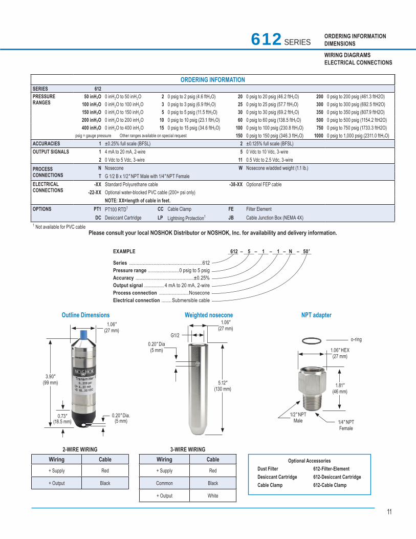
ORDERING INFORMATIONDIMENSIONS
WIRING DIAGRAMSELECTRICAL CONNECTIONS
ORDERING INFORMATIONSERIES 612 PRESSURERANGES
50 inH2O 0 inH2O to 50 inH2O 2 0 psig to 2 psig (4.6 ftH2O) 20 0 psig to 20 psig (46.2 ftH2O) 200 0 psig to 200 psig (461.3 ftH2O) 100 inH2O 0 inH2O to 100 inH2O 3 0 psig to 3 psig (6.9 ftH2O) 25 0 psig to 25 psig (57.7 ftH2O) 300 0 psig to 300 psig (692.5 ftH2O)150 inH2O 0 inH2O to 150 inH2O 5 0 psig to 5 psig (11.5 ftH2O) 30 0 psig to 30 psig (69.2 ftH2O) 350 0 psig to 350 psig (807.9 ftH2O) 200 inH2O 0 inH2O to 200 inH2O 10 0 psig to 10 psig (23.1 ftH2O) 60 0 psig to 60 psig (138.5 ftH2O) 500 0 psig to 500 psig (1154.2 ftH2O) 400 inH2O 0 inH2O to 400 inH2O 15 0 psig to 15 psig (34.6 ftH2O) 100 0 psig to 100 psig (230.8 ftH2O) 750 0 psig to 750 psig (1733.3 ftH2O)
psig = gauge pressure Other ranges available on special request 150 0 psig to 150 psig (346.3 ftH2O) 1000 0 psig to 1,000 psig (2311.0 ftH2O) ACCURACIES 1 ±0.25% full scale (BFSL) 2 ±0.125% full scale (BFSL)OUTPUT SIGNALS 1 4 mA to 20 mA, 2-wire 5 0 Vdc to 10 Vdc, 3-wire
2 0 Vdc to 5 Vdc, 3-wire 11 0.5 Vdc to 2.5 Vdc, 3-wirePROCESSCONNECTIONS
N Nosecone W Nosecone w/added weight (1.1 lb.)T G 1/2 B x 1/2″ NPT Male with 1/4″ NPT Female
ELECTRICALCONNECTIONS
-XX Standard Polyurethane cable -38-XX Optional FEP cable -22-XX Optional water-blocked PVC cable (200+ psi only)
NOTE: XX=length of cable in feet.OPTIONS PT1 PT100 RTD1 CC Cable Clamp FE Filter Element
DC Desiccant Cartridge LP Lightning Protection1 JB Cable Junction Box (NEMA 4X)1 Not available for PVC cable
Please consult your local NOSHOK Distributor or NOSHOK, Inc. for availability and delivery information.
2-WIRE WIRING Wiring Cable
+ Supply Red
+ Output Black
612 – 5 – 1 – 1 – N – 50' EXAMPLE
Series ...........................................................612Pressure range .........................0 psig to 5 psigAccuracy ...............................................±0.25%Output signal ................ 4 mA to 20 mA, 2-wireProcess connection ........................NoseconeElectrical connection ........Submersible cable
612 SERIES
3-WIRE WIRING Wiring Cable
+ Supply Red
Common Black
+ Output White
3.90″(99 mm)
0.20″ Dia.(5 mm)
0.73″(18.5 mm)
1.06″(27 mm)
5.12″(130 mm)
0.20″ Dia(5 mm)
G1/2
1.06″(27 mm)
o-ring
1.81″(46 mm)
1.06″ HEX(27 mm)
1/2″ NPTMale 1/4″ NPT
Female
Optional Accessories Dust Filter 612-Filter-Element Desiccant Cartridge 612-Desiccant Cartridge Cable Clamp 612-Cable Clamp
Outline Dimensions Weighted nosecone NPT adapter
12
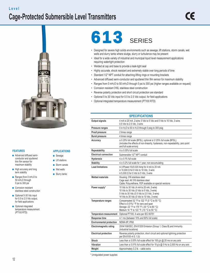
APPLICATIONS ■ Sewage ■ Lift stations ■ Storm canals ■ Wet wells ■ Slurry tanks
FEATURES ■ Advanced diffused semi-
conductor and sputtered thin film sensor for maximum stability
■ High accuracy and long term stability
■ Ranges from 0 inH2O to 50 inH2O through 0 psi to 300 psi
■ Corrosion resistant stainless steel construction
■ Optional 5-30 Vdc input for 0.5 to 2.5 Vdc output, for field applications
■ Optional integrated temperature measurement (PT100 RTD)
SPECIFICATIONS Output signals 4 mA to 20 mA, 2-wire; 0 Vdc to 5 Vdc and 0 Vdc to 10 Vdc, 3-wire;
0.5 Vdc to 2.5 Vdc, 3-wirePressure ranges 0 in H2O to 50 in H2O through 0 psig to 300 psigProof pressure 2 times rangeBurst pressure 4 times rangeAccuracy ± 0.25% full scale (BFSL); optional ± 0.125% full scale (BFSL);
(includes the effects of non-linearity, hysteresis, non-repeatability, zero pointand full scale errors)
Repeatability ≤ ± 0.05% full scaleElectrical connection Submersible 1/2″ NPT conduitHysteresis ≤ ± 0.1% full scaleStability ≤ ± 0.2% full scale for 1 year, non-accumulatingLoad limitations ≤ (VPower-10)/0.020 Amp for 4 mA to 20 mA
≥ 10,000 Ω for 0 Vdc to 10 Vdc, 3-wire≥ 5,000 Ω for 0 Vdc to 5 Vdc, 3-wire
Wetted materials Housing: 316 stainless steelCage seal: All 316 stainless steelCable: Polyurethane, FEP available on special versions
Power supply* 10 Vdc to 30 Vdc (4 mA to 20 mA, 2-wire)10 Vdc to 30 Vdc (0 Vdc to 5 Vdc, 3-wire)5 Vdc to 30 Vdc (0.5 Vdc to 2.5 Vdc, 3-wire)14 Vdc to 30 Vdc (0 Vdc to 10 Vdc, 3-wire)
Temperature ranges Compensated 32 °F to 122 °F (0 °C to 50 °C)Effect ± 0.01%/ °F for zero and spanStorage -22 °F to 175 °F (-30 °C to 80 °C)Medium 14 °F to 122 °F (-10 °C to 50 °C)
Temperature measurement Optional PT100, 4-wire per IEC 60751Response time ≤ 1 ms (between 10% and 90% full scale)Environmental protection NEMA 6P, IP68Electromagnetic rating 2004/108/EEC, EN 61326 Emission (Group 1, Class B) and Immunity
(industrial locations)Electrical protection Reverse polarity protection, short circuit and optional lightning protection
per EN 6100-4-5; 1.5JShock Less than ± 0.05% full scale effect for 100 g’s @ 20 ms on any axisVibration Less than ± 0.01% full scale effect for 15 g’s @ 0 Hz to 2,000 Hz on any axisWeight Approximately 3.2 lb. - cable extra
• Designed for severe high solids environments such as sewage, lift stations, storm canals, wet wells and slurry tanks where sludge, slurry or turbulence may be present• Ideal for a wide variety of industrial and municipal liquid level measurement applications requiring watertight protection• Welded at cap and base to provide a leak-tight seal• Highly accurate, shock resistant and extremely stable over long periods of time• Standard 1/2″ NPT conduit for attaching lifting rings or mounting brackets• Advanced diffused semi-conductor and sputtered thin fi lm sensor for maximum stability• Ranges from 0 inH2O to 50 inH2O through 0 psi to 300 psi (higher ranges available on request)• Corrosion resistant 316L stainless steel construction• Reverse polarity protection and short circuit protection are standard• Optional 5 to 30 Vdc input for 0.5 to 2.5 Vdc output, for fi eld applications• Optional integrated temperature measurement (PT100 RTD)
L e v e l
Cage-Protected Submersible Level Transmitters
613 613 SERIES
* Unregulated power supplies
13
ORDERING INFORMATIONDIMENSIONS
WIRING DIAGRAMSELECTRICAL CONNECTIONS
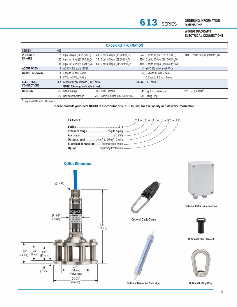
Outline Dimensions
613 – 5 – 1 – 1 – 50' – LP EXAMPLE
Series ...........................................................613Pressure range .........................0 psig to 5 psigAccuracy ...............................................±0.25%Output signal ................ 4 mA to 20 mA, 2-wireElectrical connection ........Submersible cableOption .................................Lightning Protection
ORDERING INFORMATIONSERIES 613 PRESSURE RANGES
5 0 psi to 5 psi (11.55 ft/H2O) 20 0 psi to 20 psi (46.20 ft/H2O) 75 0 psi to 75 psi (173.25 ft/H2O) 300 0 psi to 300 psi (693 ft/H2O)10 0 psi to 10 psi (23.10 ft/H2O) 30 0 psi to 30 psi (69.30 ft/H2O) 100 0 psi to 100 psi (231.00 ft/H2O)15 0 psi to 15 psi (34.65 ft/H2O) 50 0 psi to 50 psi (115.50 ft/H2O) 150 0 psi to 150 psi (346.50 ft/H2O)
ACCURACIES 1 ±0.25% full scale (BFSL) 2 ±0.125% full scale (BFSL)OUTPUT SIGNALS 1 4 mA to 20 mA, 2-wire 5 0 Vdc to 10 Vdc, 3-wire
2 0 Vdc to 5 Vdc, 3-wire 11 0.5 Vdc to 2.5 Vdc, 3-wireELECTRICALCONNECTIONS
-XX Standard Polyurethane (PUR) cable -38-XX FEP cable NOTE: XX=length of cable in feet.
OPTIONS CC Cable Clamp FE Filter Element LP Lightning Protection1 PT1 PT100 RTD1
DC Desiccant Cartridge JB Cable Junction Box (NEMA 4X) LR Lifting Ring1 Only available with PUR cable
Please consult your local NOSHOK Distributor or NOSHOK, Inc. for availability and delivery information.
613 SERIES
1.06″(27 mm)
2.14″(54 mm)
Active areaØ 3.75″(95 mm)
4.44″(113 mm)
Ø 1.06″(27 mm)
1/2″ NPT
1.25″(32 mm)
1.75″(44 mm)
.25″(6 mm)
Optional Lifting Ring
Optional Cable Junction Box
Optional Desiccant Cartridge
Optional Cable Clamp
Optional Filter Element
14
P r e s s u r e
High Accuracy Heavy-Duty Pressure Transducers
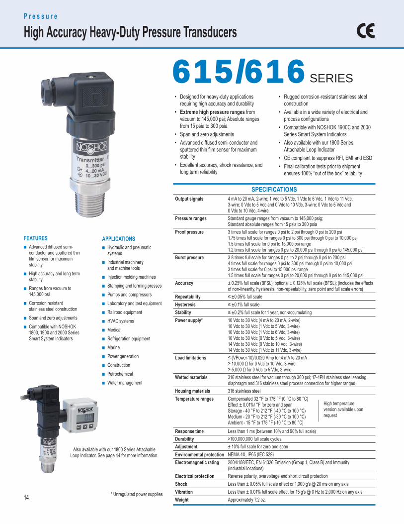
APPLICATIONS ■ Hydraulic and pneumatic
systems ■ Industrial machinery
and machine tools ■ Injection molding machines ■ Stamping and forming presses ■ Pumps and compressors ■ Laboratory and test equipment ■ Railroad equipment ■ HVAC systems ■ Medical ■ Refrigeration equipment ■ Marine ■ Power generation ■ Construction ■ Petrochemical ■ Water management
FEATURES ■ Advanced diffused semi-
conductor and sputtered thin film sensor for maximum stability
■ High accuracy and long term stability
■ Ranges from vacuum to 145,000 psi
■ Corrosion resistant stainless steel construction
■ Span and zero adjustments ■ Compatible with NOSHOK
1800, 1900 and 2000 Series Smart System Indicators
• Designed for heavy-duty applications requiring high accuracy and durability• Extreme high pressure ranges from vacuum to 145,000 psi; Absolute ranges from 15 psia to 300 psia• Span and zero adjustments• Advanced diffused semi-conductor and sputtered thin fi lm sensor for maximum stability• Excellent accuracy, shock resistance, and long term reliability
• Rugged corrosion-resistant stainless steel construction• Available in a wide variety of electrical and process confi gurations• Compatible with NOSHOK 1900C and 2000 Series Smart System Indicators• Also available with our 1800 Series Attachable Loop Indicator• CE compliant to suppress RFI, EMI and ESD• Final calibration tests prior to shipment ensures 100% “out of the box” reliability
615/616 615/616 SERIES
SPECIFICATIONS Output signals 4 mA to 20 mA, 2-wire; 1 Vdc to 5 Vdc, 1 Vdc to 6 Vdc, 1 Vdc to 11 Vdc,
3-wire; 0 Vdc to 5 Vdc and 0 Vdc to 10 Vdc, 3-wire; 0 Vdc to 5 Vdc and0 Vdc to 10 Vdc, 4-wire
Pressure ranges Standard gauge ranges from vacuum to 145,000 psig;Standard absolute ranges from 15 psia to 300 psia
Proof pressure 3 times full scale for ranges 0 psi to 2 psi through 0 psi to 200 psi1.75 times full scale for ranges 0 psi to 300 psi through 0 psi to 10,000 psi1.5 times full scale for 0 psi to 15,000 psi range1.2 times full scale for ranges 0 psi to 20,000 psi through 0 psi to 145,000 psi
Burst pressure 3.8 times full scale for ranges 0 psi to 2 psi through 0 psi to 200 psi4 times full scale for ranges 0 psi to 300 psi through 0 psi to 10,000 psi3 times full scale for 0 psi to 15,000 psi range1.5 times full scale for ranges 0 psi to 20,000 psi through 0 psi to 145,000 psi
Accuracy ± 0.25% full scale (BFSL); optional ± 0.125% full scale (BFSL); (includes the effects of non-linearity, hysteresis, non-repeatability, zero point and full scale errors)
Repeatability ≤ ±0.05% full scaleHysteresis ≤ ±0.1% full scaleStability ≤ ±0.2% full scale for 1 year, non-accumulatingPower supply* 10 Vdc to 30 Vdc (4 mA to 20 mA, 2-wire)
10 Vdc to 30 Vdc (1 Vdc to 5 Vdc, 3-wire)10 Vdc to 30 Vdc (1 Vdc to 6 Vdc, 3-wire)10 Vdc to 30 Vdc (0 Vdc to 5 Vdc, 3-wire)14 Vdc to 30 Vdc (0 Vdc to 10 Vdc, 3-wire) 14 Vdc to 30 Vdc (1 Vdc to 11 Vdc, 3-wire)
Load limitations ≤ (VPower-10)/0.020 Amp for 4 mA to 20 mA≥ 10,000 Ω for 0 Vdc to 10 Vdc, 3-wire≥ 5,000 Ω for 0 Vdc to 5 Vdc, 3-wire
Wetted materials 316 stainless steel for vacuum through 300 psi; 17-4PH stainless steel sensing diaphragm and 316 stainless steel process connection for higher ranges
Housing materials 316 stainless steelTemperature ranges Compensated 32 °F to 175 °F (0 °C to 80 °C)
Effect ± 0.01%/ °F for zero and spanStorage - 40 °F to 212 °F (-40 °C to 100 °C)Medium - 20 °F to 212 °F (-30 °C to 100 °C)Ambient - 15 °F to 175 °F (-10 °C to 80 °C)
Response time Less than 1 ms (between 10% and 90% full scale)Durability >100,000,000 full scale cyclesAdjustment ± 10% full scale for zero and spanEnvironmental protection NEMA 4X, IP65 (IEC 529)Electromagnetic rating 2004/108/EEC, EN 61326 Emission (Group 1, Class B) and Immunity
(industrial locations)Electrical protection Reverse polarity, overvoltage and short circuit protectionShock Less than ± 0.05% full scale effect or 1,000 g’s @ 20 ms on any axisVibration Less than ± 0.01% full scale effect for 15 g’s @ 0 Hz to 2,000 Hz on any axisWeight Approximately 7.2 oz.
High temperature version available upon request
Also available with our 1800 Series Attachable Loop Indicator. See page 44 for more information.
* Unregulated power supplies
15
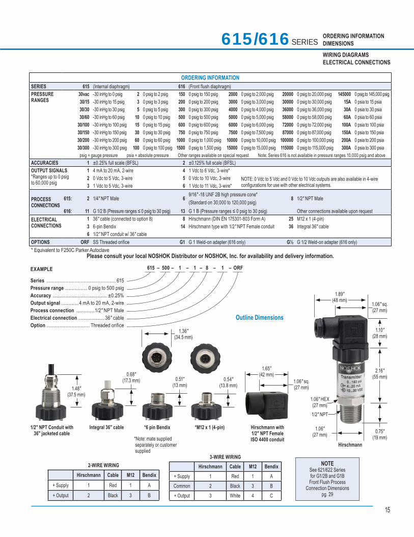
3-WIRE WIRING Hirschmann Cable M12 Bendix
+ Supply 1 Red 1 A
Common 2 Black 3 B
+ Output 3 White 4 C
ORDERING INFORMATIONDIMENSIONS
WIRING DIAGRAMSELECTRICAL CONNECTIONS
615/616 SERIES
2-WIRE WIRING
Hirschmann Cable M12 Bendix
+ Supply 1 Red 1 A
+ Output 2 Black 3 B
Hirschmann
1.06"(27 mm)
1.89"(48 mm)
1.06" sq.(27 mm)
1.10"(28 mm)
2.16"(55 mm)
0.75"(19 mm)
1/2" NPT
1.06" HEX(27 mm)
NOTESee 621/622 Seriesfor G1/2B and G1B
Front Flush ProcessConnection Dimensions
pg. 29
1.36″(34.5 mm)
1/2″ NPT Conduit with 36″ jacketed cable
1.48"(37.5 mm)
Integral 36″ cable
0.68"(17.3 mm)
*6 pin Bendix
0.51"(13 mm)
*M12 x 1 (4-pin)
0.54"(13.8 mm)
Hirschmann with1/2″ NPT FemaleISO 4400 conduit
1.65"(42 mm)
1.06" sq.(27 mm)
*Note: mate supplied separately or customer supplied
615 – 500 – 1 – 1 – 8 – 1 – ORF EXAMPLE
Series ........................................................ 615Pressure range .................. 0 psig to 500 psigAccuracy ............................................ ±0.25%Output signal ..............4 mA to 20 mA, 2-wireProcess connection ...............1/2″ NPT MaleElectrical connection .....................36″ cableOption ................................... Threaded orifice
Outline Dimensions
ORDERING INFORMATIONSERIES 615 (Internal diaphragm) 616 (Front flush diaphragm) PRESSURE RANGES
30vac -30 inHg to 0 psig 2 0 psig to 2 psig 150 0 psig to 150 psig 2000 0 psig to 2,000 psig 20000 0 psig to 20,000 psig 145000 0 psig to 145,000 psig 30/15 -30 inHg to 15 psig 3 0 psig to 3 psig 200 0 psig to 200 psig 3000 0 psig to 3,000 psig 30000 0 psig to 30,000 psig 15A 0 psia to 15 psia 30/30 -30 inHg to 30 psig 5 0 psig to 5 psig 300 0 psig to 300 psig 4000 0 psig to 4,000 psig 36000 0 psig to 36,000 psig 30A 0 psia to 30 psia 30/60 -30 inHg to 60 psig 10 0 psig to 10 psig 500 0 psig to 500 psig 5000 0 psig to 5,000 psig 58000 0 psig to 58,000 psig 60A 0 psia to 60 psia
30/100 -30 inHg to 100 psig 15 0 psig to 15 psig 600 0 psig to 600 psig 6000 0 psig to 6,000 psig 72000 0 psig to 72,000 psig 100A 0 psia to 100 psia 30/150 -30 inHg to 150 psig 30 0 psig to 30 psig 750 0 psig to 750 psig 7500 0 psig to 7,500 psig 87000 0 psig to 87,000 psig 150A 0 psia to 150 psia30/200 -30 inHg to 200 psig 60 0 psig to 60 psig 1000 0 psig to 1,000 psig 10000 0 psig to 10,000 psig 100000 0 psig to 100,000 psig 200A 0 psia to 200 psia30/300 -30 inHg to 300 psig 100 0 psig to 100 psig 1500 0 psig to 1,500 psig 15000 0 psig to 15,000 psig 115000 0 psig to 115,000 psig 300A 0 psia to 300 psia
psig = gauge pressure psia = absolute pressure Other ranges available on special request Note: Series 616 is not available in pressure ranges 10,000 psig and above ACCURACIES 1 ±0.25% full scale (BFSL) 2 ±0.125% full scale (BFSL)OUTPUT SIGNALS *Ranges up to 0 psig to 60,000 psig
1 4 mA to 20 mA, 2-wire 4 1 Vdc to 6 Vdc, 3-wire*2 0 Vdc to 5 Vdc, 3-wire 5 0 Vdc to 10 Vdc, 3-wire NOTE: 0 Vdc to 5 Vdc and 0 Vdc to 10 Vdc outputs are also available in 4-wire
configurations for use with other electrical systems.3 1 Vdc to 5 Vdc, 3-wire 6 1 Vdc to 11 Vdc, 3-wire*
PROCESSCONNECTIONS
615: 2 1/4″ NPT Male 6 9/16″ -18 UNF 2B high pressure cone*(Standard on 30,000 to 120,000 psig)
8 1/2″ NPT Male
616: 11 G 1/2 B (Pressure ranges ≤ 0 psig to 30 psig) 13 G 1 B (Pressure ranges ≤ 0 psig to 30 psig) Other connections available upon requestELECTRICALCONNECTIONS
1 36″ cable (connected to option 8) 8 Hirschmann (DIN EN 175301-803 Form A) 25 M12 x 1 (4-pin)3 6-pin Bendix 14 Hirschmann type with 1/2″ NPT Female conduit 36 Integral 36″ cable6 1/2″ NPT conduit w/ 36″ cable
OPTIONS ORF SS Threaded orifice G1 G 1 Weld-on adapter (616 only) G½ G 1/2 Weld-on adapter (616 only)* Equivalent to F250C Parker Autoclave
Please consult your local NOSHOK Distributor or NOSHOK, Inc. for availability and delivery information.
16
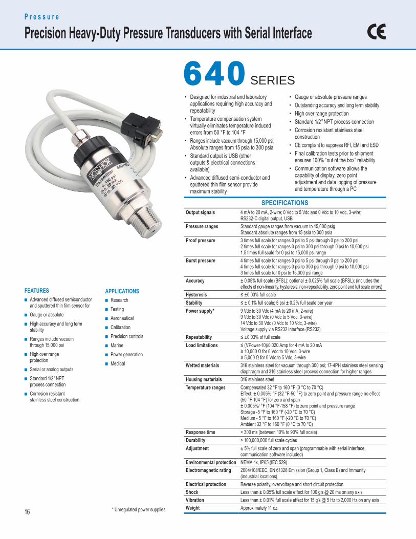
SPECIFICATIONS Output signals 4 mA to 20 mA, 2-wire; 0 Vdc to 5 Vdc and 0 Vdc to 10 Vdc, 3-wire;
RS232-C digital output, USBPressure ranges Standard gauge ranges from vacuum to 15,000 psig
Standard absolute ranges from 15 psia to 300 psiaProof pressure 3 times full scale for ranges 0 psi to 5 psi through 0 psi to 200 psi
2 times full scale for ranges 0 psi to 300 psi through 0 psi to 10,000 psi1.5 times full scale for 0 psi to 15,000 psi range
Burst pressure 4 times full scale for ranges 0 psi to 5 psi through 0 psi to 200 psi4 times full scale for ranges 0 psi to 300 psi through 0 psi to 10,000 psi3 times full scale for 0 psi to 15,000 psi range
Accuracy ± 0.05% full scale (BFSL); optional ± 0.025% full scale (BFSL); (includes the effects of non-linearity, hysteresis, non-repeatability, zero point and full scale errors)
Hysteresis ≤ ±0.03% full scaleStability ≤ ± 0.1% full scale; 5 psi ± 0.2% full scale per yearPower supply* 9 Vdc to 30 Vdc (4 mA to 20 mA, 2-wire)
9 Vdc to 30 Vdc (0 Vdc to 5 Vdc, 3-wire)14 Vdc to 30 Vdc (0 Vdc to 10 Vdc, 3-wire)Voltage supply via RS232 interface (RS232)
Repeatability ≤ ±0.03% of full scaleLoad limitations ≤ (VPower-10)/0.020 Amp for 4 mA to 20 mA
≥ 10,000 Ω for 0 Vdc to 10 Vdc, 3-wire≥ 5,000 Ω for 0 Vdc to 5 Vdc, 3-wire
Wetted materials 316 stainless steel for vacuum through 300 psi; 17-4PH stainless steel sensing diaphragm and 316 stainless steel process connection for higher ranges
Housing materials 316 stainless steel Temperature ranges Compensated 32 °F to 160 °F (0 °C to 70 °C)
Effect: ± 0.005% °F (32 °F-50 °F) to zero point and pressure range no effect (50 °F-104 °F) for zero and span± 0.005%/ °F (104 °F-158 °F) to zero point and pressure rangeStorage -5 °F to 160 °F (-20 °C to 70 °C)Medium - 5 °F to 160 °F (-20 °C to 70 °C)Ambient 32 °F to 160 °F (0 °C to 70 °C)
Response time < 300 ms (between 10% to 90% full scale)Durability > 100,000,000 full scale cyclesAdjustment ± 5% full scale of zero and span (programmable with serial interface,
communication software included) Environmental protection NEMA 4x, IP65 (IEC 529) Electromagnetic rating 2004/108/EEC, EN 61326 Emission (Group 1, Class B) and Immunity
(industrial locations) Electrical protection Reverse polarity, overvoltage and short circuit protection Shock Less than ± 0.05% full scale effect for 100 g’s @ 20 ms on any axisVibration Less than ± 0.01% full scale effect for 15 g’s @ 5 Hz to 2,000 Hz on any axisWeight Approximately 11 oz.
APPLICATIONS ■ Research ■ Testing ■ Aeronautical ■ Calibration ■ Precision controls ■ Marine ■ Power generation ■ Medical
FEATURES ■ Advanced diffused semiconductor
and sputtered thin film sensor for ■ Gauge or absolute ■ High accuracy and long term
stability ■ Ranges include vacuum
through 15,000 psi ■ High over range
protection ■ Serial or analog outputs ■ Standard 1/2″ NPT
process connection ■ Corrosion resistant
stainless steel construction
P r e s s u r e
Precision Heavy-Duty Pressure Transducers with Serial Interface
640 640 SERIES• Designed for industrial and laboratory applications requiring high accuracy and repeatability• Temperature compensation system virtually eliminates temperature induced errors from 50 °F to 104 °F• Ranges include vacuum through 15,000 psi; Absolute ranges from 15 psia to 300 psia• Standard output is USB (other outputs & electrical connections available)• Advanced diffused semi-conductor and sputtered thin fi lm sensor provide maximum stability
• Gauge or absolute pressure ranges• Outstanding accuracy and long term stability• High over range protection• Standard 1/2” NPT process connection• Corrosion resistant stainless steel construction• CE compliant to suppress RFI, EMI and ESD• Final calibration tests prior to shipment ensures 100% “out of the box” reliability• Communication software allows the capability of display, zero point adjustment and data logging of pressure and temperature through a PC
* Unregulated power supplies
17
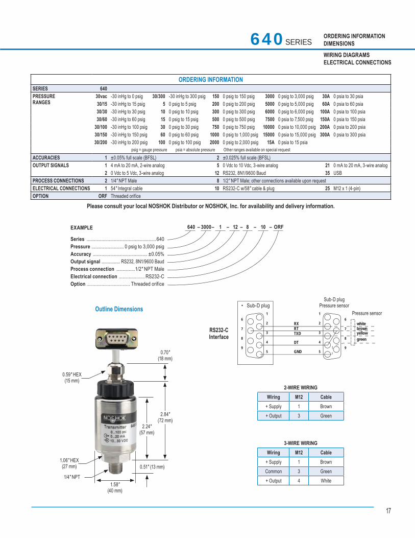
ORDERING INFORMATIONDIMENSIONS
WIRING DIAGRAMSELECTRICAL CONNECTIONS
Outline Dimensions
2-WIRE WIRING Wiring M12 Cable
+ Supply 1 Brown+ Output 3 Green
640 – 3000 – 1 – 12 – 8 – 10 – ORF EXAMPLE
Series ........................................................640Pressure .......................... 0 psig to 3,000 psigAccuracy ............................................ ±0.05%Output signal ............... RS232, 8N1/9600 BaudProcess connection ...............1/2″ NPT MaleElectrical connection ..................... RS232-COption ................................... Threaded orifice
640 SERIES
3-WIRE WIRING Wiring M12 Cable
+ Supply 1 BrownCommon 3 Green+ Output 4 White
1
2
3
4
5
1
2
3
4
5
6
7
8
9
6
7
8
9
RX whitebrownyellow
RTTXD
DT
GND
green
RS232-CInterface
• Sub-D plugSub-D plug
Pressure sensorPressure sensor
0.59" HEX(15 mm)
1.06" HEX(27 mm)
1/4" NPT1.58"
(40 mm)
0.51" (13 mm)
2.24"(57 mm)
2.84"(72 mm)
0.70"(18 mm)
ORDERING INFORMATIONSERIES 640PRESSURE RANGES
30vac -30 inHg to 0 psig 30/300 -30 inHg to 300 psig 150 0 psig to 150 psig 3000 0 psig to 3,000 psig 30A 0 psia to 30 psia 30/15 -30 inHg to 15 psig 5 0 psig to 5 psig 200 0 psig to 200 psig 5000 0 psig to 5,000 psig 60A 0 psia to 60 psia 30/30 -30 inHg to 30 psig 10 0 psig to 10 psig 300 0 psig to 300 psig 6000 0 psig to 6,000 psig 100A 0 psia to 100 psia 30/60 -30 inHg to 60 psig 15 0 psig to 15 psig 500 0 psig to 500 psig 7500 0 psia to 7,500 psig 150A 0 psia to 150 psia
30/100 -30 inHg to 100 psig 30 0 psig to 30 psig 750 0 psig to 750 psig 10000 0 psia to 10,000 psig 200A 0 psia to 200 psia 30/150 -30 inHg to 150 psig 60 0 psig to 60 psig 1000 0 psig to 1,000 psig 15000 0 psia to 15,000 psig 300A 0 psia to 300 psia30/200 -30 inHg to 200 psig 100 0 psig to 100 psig 2000 0 psig to 2,000 psig 15A 0 psia to 15 psia
psig = gauge pressure psia = absolute pressure Other ranges available on special request ACCURACIES 1 ±0.05% full scale (BFSL) 2 ±0.025% full scale (BFSL)OUTPUT SIGNALS 1 4 mA to 20 mA, 2-wire analog 5 0 Vdc to 10 Vdc, 3-wire analog 21 0 mA to 20 mA, 3-wire analog
2 0 Vdc to 5 Vdc, 3-wire analog 12 RS232, 8N1/9600 Baud 35 USBPROCESS CONNECTIONS 2 1/4″ NPT Male 8 1/2″ NPT Male; other connections available upon request ELECTRICAL CONNECTIONS 1 54″ Integral cable 10 RS232-C w/58″ cable & plug 25 M12 x 1 (4-pin)OPTION ORF Threaded orifice
Please consult your local NOSHOK Distributor or NOSHOK, Inc. for availability and delivery information.
18
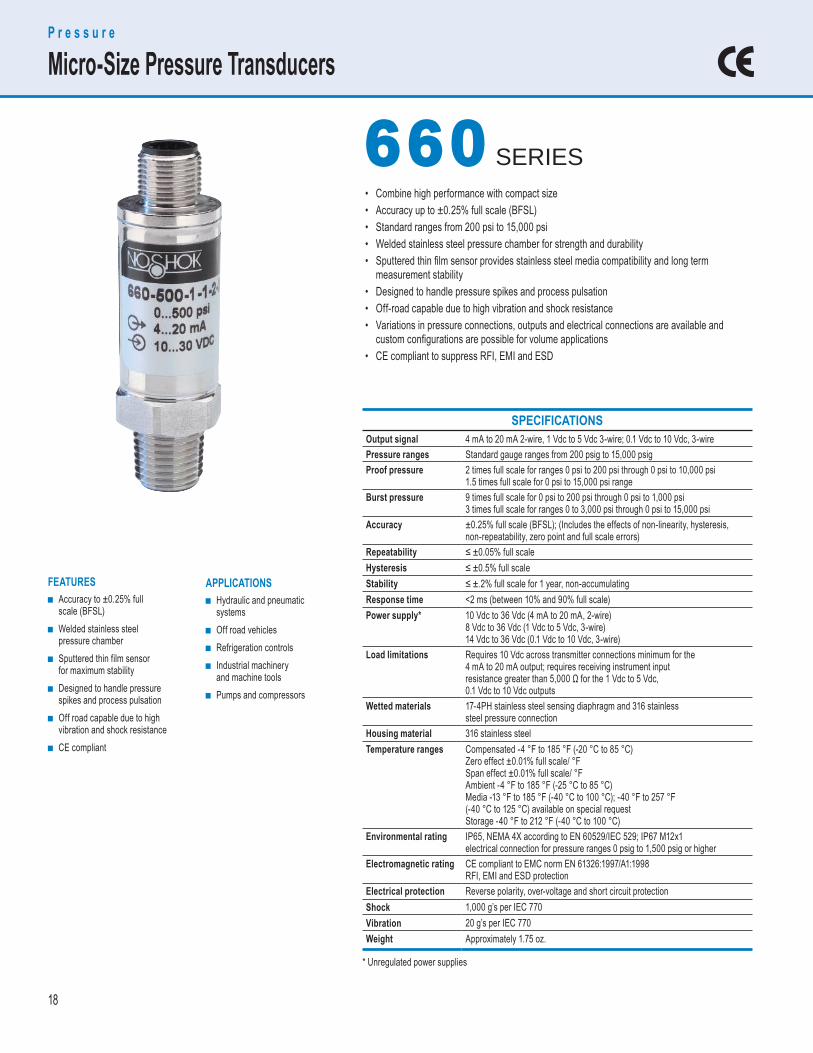
SPECIFICATIONS Output signal 4 mA to 20 mA 2-wire, 1 Vdc to 5 Vdc 3-wire; 0.1 Vdc to 10 Vdc, 3-wirePressure ranges Standard gauge ranges from 200 psig to 15,000 psigProof pressure 2 times full scale for ranges 0 psi to 200 psi through 0 psi to 10,000 psi
1.5 times full scale for 0 psi to 15,000 psi rangeBurst pressure 9 times full scale for 0 psi to 200 psi through 0 psi to 1,000 psi
3 times full scale for ranges 0 to 3,000 psi through 0 psi to 15,000 psiAccuracy ±0.25% full scale (BFSL); (Includes the effects of non-linearity, hysteresis,
non-repeatability, zero point and full scale errors)Repeatability ≤ ±0.05% full scaleHysteresis ≤ ±0.5% full scaleStability ≤ ±.2% full scale for 1 year, non-accumulatingResponse time <2 ms (between 10% and 90% full scale)Power supply* 10 Vdc to 36 Vdc (4 mA to 20 mA, 2-wire)
8 Vdc to 36 Vdc (1 Vdc to 5 Vdc, 3-wire)14 Vdc to 36 Vdc (0.1 Vdc to 10 Vdc, 3-wire)
Load limitations Requires 10 Vdc across transmitter connections minimum for the 4 mA to 20 mA output; requires receiving instrument input resistance greater than 5,000 Ω for the 1 Vdc to 5 Vdc,0.1 Vdc to 10 Vdc outputs
Wetted materials 17-4PH stainless steel sensing diaphragm and 316 stainlesssteel pressure connection
Housing material 316 stainless steelTemperature ranges Compensated -4 °F to 185 °F (-20 °C to 85 °C)
Zero effect ±0.01% full scale/ °FSpan effect ±0.01% full scale/ °FAmbient -4 °F to 185 °F (-25 °C to 85 °C)Media -13 °F to 185 °F (-40 °C to 100 °C); -40 °F to 257 °F (-40 °C to 125 °C) available on special requestStorage -40 °F to 212 °F (-40 °C to 100 °C)
Environmental rating IP65, NEMA 4X according to EN 60529/IEC 529; IP67 M12x1electrical connection for pressure ranges 0 psig to 1,500 psig or higher
Electromagnetic rating CE compliant to EMC norm EN 61326:1997/A1:1998RFI, EMI and ESD protection
Electrical protection Reverse polarity, over-voltage and short circuit protectionShock 1,000 g’s per IEC 770Vibration 20 g’s per IEC 770Weight Approximately 1.75 oz.
• Combine high performance with compact size• Accuracy up to ±0.25% full scale (BFSL)• Standard ranges from 200 psi to 15,000 psi• Welded stainless steel pressure chamber for strength and durability• Sputtered thin fi lm sensor provides stainless steel media compatibility and long term measurement stability• Designed to handle pressure spikes and process pulsation• Off-road capable due to high vibration and shock resistance• Variations in pressure connections, outputs and electrical connections are available and custom confi gurations are possible for volume applications• CE compliant to suppress RFI, EMI and ESD
APPLICATIONS ■ Hydraulic and pneumatic
systems ■ Off road vehicles ■ Refrigeration controls ■ Industrial machinery
and machine tools ■ Pumps and compressors
FEATURES ■ Accuracy to ±0.25% full
scale (BFSL) ■ Welded stainless steel
pressure chamber ■ Sputtered thin film sensor
for maximum stability ■ Designed to handle pressure
spikes and process pulsation ■ Off road capable due to high
vibration and shock resistance ■ CE compliant
P r e s s u r e
Micro-Size Pressure Transducers
660 660 SERIES
* Unregulated power supplies
19
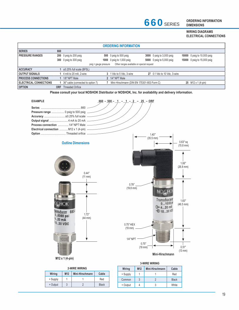
ORDERING INFORMATIONDIMENSIONS
WIRING DIAGRAMSELECTRICAL CONNECTIONS
Outline Dimensions
EXAMPLE
Series ........................................................660Pressure range .................. 0 psig to 500 psigAccuracy .............................±0.25% full scaleOutput signal .......................... 4 mA to 20 mAProcess connection ...............1/4″ NPT MaleElectrical connection ............M12 x 1 (4-pin)Option ................................... Threaded orifice
660 – 500 – 1 – 1 – 2 – 25 – ORF
660 SERIES
3-WIRE WIRING Wiring M12 Mini-Hirschmann Cable
+ Supply 1 1 RedCommon 3 2 Black+ Output 4 3 White
2-WIRE WIRING Wiring M12 Mini-Hirschmann Cable
+ Supply 1 1 Red+ Output 3 2 Black
M12 x 1 (4-pin)
0.44"(11 mm)
1.73"(44 mm)
0.63" sq(15.8 mm)
1.83"(46.5 mm)
1.06"(26.8 mm)
1.40"(35.5 mm)
0.78”(19.8 mm)
0.75" HEX(19 mm)
1/4" NPT0.75"
(19 mm) 0.51"(13 mm)
Mini-Hirschmann
ORDERING INFORMATIONSERIES 660 PRESSURE RANGES 200 0 psig to 200 psig 500 0 psig to 500 psig 3000 0 psig to 3,000 psig 10000 0 psig to 10,000 psig
300 0 psig to 300 psig 1000 0 psig to 1,000 psig 5000 0 psig to 5,000 psig 15000 0 psig to 15,000 psig psig = gauge pressure Other ranges available on special request
ACCURACY 1 ±0.25% full scale (BFSL)OUTPUT SIGNALS 1 4 mA to 20 mA, 2-wire 3 1 Vdc to 5 Vdc, 3-wire 27 0.1 Vdc to 10 Vdc, 3-wirePROCESS CONNECTIONS 1 1/8″ NPT Male 2 1/4″ NPT Male ELECTRICAL CONNECTIONS 1 36″ cable (connected to option 7) 7 Mini-Hirschmann (DIN EN 175301-803 Form C) 25 M12 x 1 (4-pin)OPTION ORF Threaded Orifice
Please consult your local NOSHOK Distributor or NOSHOK, Inc. for availability and delivery information.
20
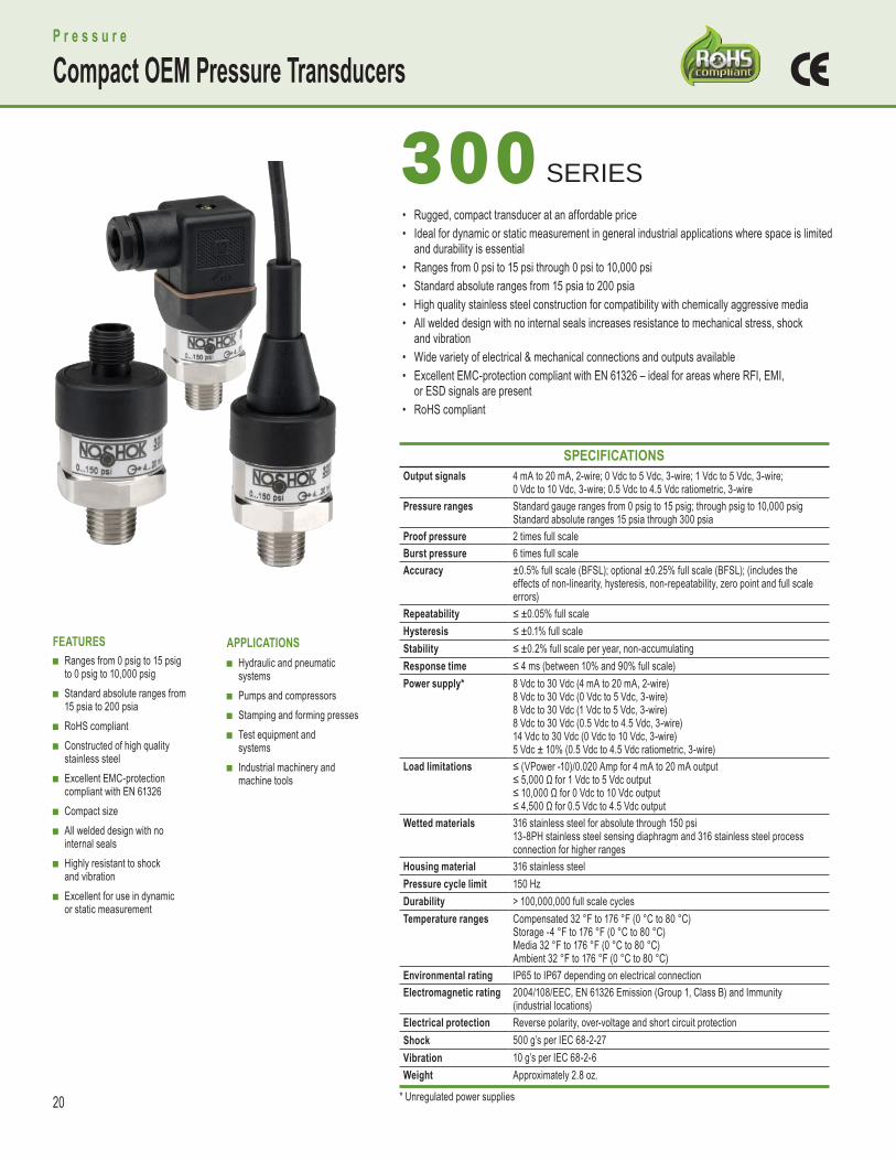
• Rugged, compact transducer at an affordable price• Ideal for dynamic or static measurement in general industrial applications where space is limited and durability is essential• Ranges from 0 psi to 15 psi through 0 psi to 10,000 psi• Standard absolute ranges from 15 psia to 200 psia• High quality stainless steel construction for compatibility with chemically aggressive media• All welded design with no internal seals increases resistance to mechanical stress, shock and vibration• Wide variety of electrical & mechanical connections and outputs available• Excellent EMC-protection compliant with EN 61326 – ideal for areas where RFI, EMI, or ESD signals are present• RoHS compliant
P r e s s u r e
Compact OEM Pressure Transducers
300 300 SERIES
APPLICATIONS ■ Hydraulic and pneumatic
systems ■ Pumps and compressors ■ Stamping and forming presses ■ Test equipment and
systems ■ Industrial machinery and
machine tools
FEATURES ■ Ranges from 0 psig to 15 psig
to 0 psig to 10,000 psig ■ Standard absolute ranges from
15 psia to 200 psia ■ RoHS compliant ■ Constructed of high quality
stainless steel ■ Excellent EMC-protection
compliant with EN 61326 ■ Compact size ■ All welded design with no
internal seals ■ Highly resistant to shock
and vibration ■ Excellent for use in dynamic
or static measurement
SPECIFICATIONS Output signals 4 mA to 20 mA, 2-wire; 0 Vdc to 5 Vdc, 3-wire; 1 Vdc to 5 Vdc, 3-wire;
0 Vdc to 10 Vdc, 3-wire; 0.5 Vdc to 4.5 Vdc ratiometric, 3-wirePressure ranges Standard gauge ranges from 0 psig to 15 psig; through psig to 10,000 psig
Standard absolute ranges 15 psia through 300 psiaProof pressure 2 times full scaleBurst pressure 6 times full scaleAccuracy ±0.5% full scale (BFSL); optional ±0.25% full scale (BFSL); (includes the
effects of non-linearity, hysteresis, non-repeatability, zero point and full scaleerrors)
Repeatability ≤ ±0.05% full scaleHysteresis ≤ ±0.1% full scaleStability ≤ ±0.2% full scale per year, non-accumulatingResponse time ≤ 4 ms (between 10% and 90% full scale)Power supply* 8 Vdc to 30 Vdc (4 mA to 20 mA, 2-wire)
8 Vdc to 30 Vdc (0 Vdc to 5 Vdc, 3-wire)8 Vdc to 30 Vdc (1 Vdc to 5 Vdc, 3-wire)8 Vdc to 30 Vdc (0.5 Vdc to 4.5 Vdc, 3-wire)14 Vdc to 30 Vdc (0 Vdc to 10 Vdc, 3-wire)5 Vdc ± 10% (0.5 Vdc to 4.5 Vdc ratiometric, 3-wire)
Load limitations ≤ (VPower -10)/0.020 Amp for 4 mA to 20 mA output≤ 5,000 Ω for 1 Vdc to 5 Vdc output≤ 10,000 Ω for 0 Vdc to 10 Vdc output≤ 4,500 Ω for 0.5 Vdc to 4.5 Vdc output
Wetted materials 316 stainless steel for absolute through 150 psi13-8PH stainless steel sensing diaphragm and 316 stainless steel processconnection for higher ranges
Housing material 316 stainless steelPressure cycle limit 150 HzDurability > 100,000,000 full scale cyclesTemperature ranges Compensated 32 °F to 176 °F (0 °C to 80 °C)
Storage -4 °F to 176 °F (0 °C to 80 °C)Media 32 °F to 176 °F (0 °C to 80 °C)Ambient 32 °F to 176 °F (0 °C to 80 °C)
Environmental rating IP65 to IP67 depending on electrical connectionElectromagnetic rating 2004/108/EEC, EN 61326 Emission (Group 1, Class B) and Immunity
(industrial locations)Electrical protection Reverse polarity, over-voltage and short circuit protectionShock 500 g’s per IEC 68-2-27Vibration 10 g’s per IEC 68-2-6Weight Approximately 2.8 oz.
* Unregulated power supplies
21
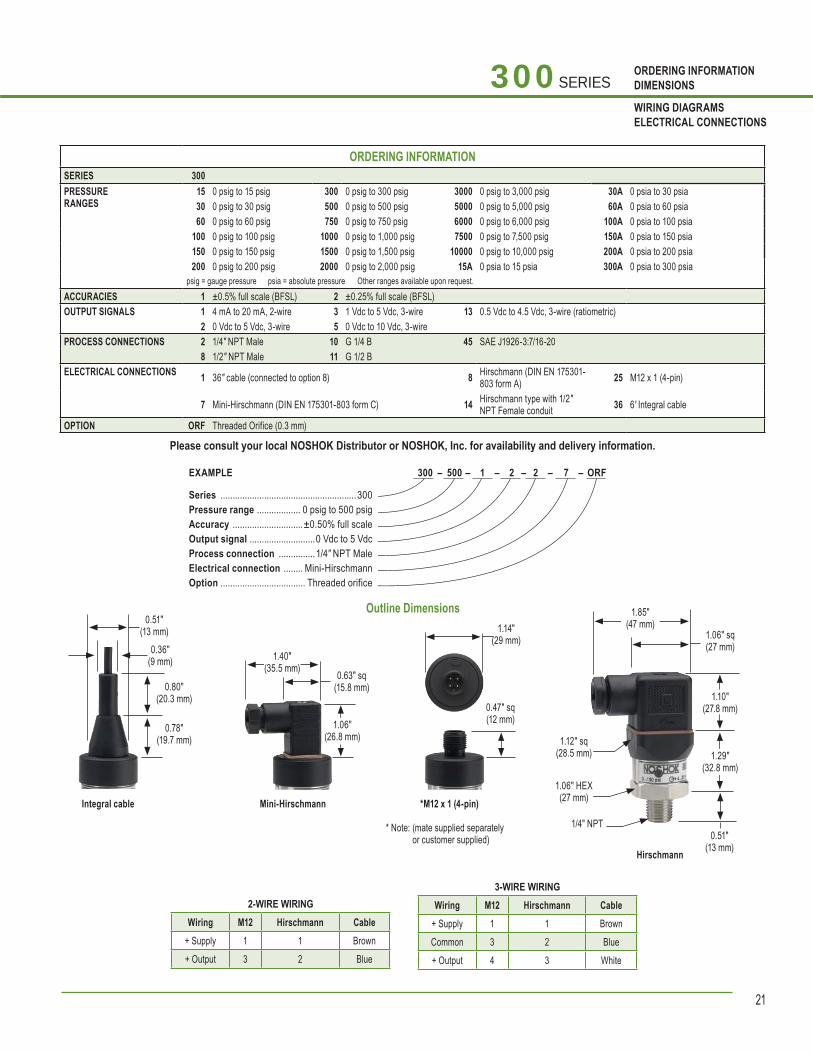
ORDERING INFORMATIONDIMENSIONS
WIRING DIAGRAMSELECTRICAL CONNECTIONS
Outline Dimensions
300 – 500 – 1 – 2 – 2 – 7 – ORF EXAMPLE
Series ........................................................300Pressure range .................. 0 psig to 500 psigAccuracy .............................±0.50% full scaleOutput signal ...........................0 Vdc to 5 VdcProcess connection ...............1/4″ NPT MaleElectrical connection ........ Mini-HirschmannOption ................................... Threaded orifice
300 SERIES
3-WIRE WIRING Wiring M12 Hirschmann Cable
+ Supply 1 1 BrownCommon 3 2 Blue+ Output 4 3 White
2-WIRE WIRING Wiring M12 Hirschmann Cable
+ Supply 1 1 Brown+ Output 3 2 Blue
0.51″(13 mm)
0.36″(9 mm)
0.80″(20.3 mm)
0.78″(19.7 mm)
Integral cable Mini-Hirschmann
1.06″(26.8 mm)
1.40″(35.5 mm) 0.63″ sq
(15.8 mm)
*M12 x 1 (4-pin)
* Note: (mate supplied separately or customer supplied)
1.14″(29 mm)
0.47″ sq(12 mm)
Hirschmann
1.85″(47 mm)
1.10″(27.8 mm)
1.29″(32.8 mm)
1.12″ sq(28.5 mm)
1.06″ HEX(27 mm)
1/4″ NPT0.51″
(13 mm)
ORDERING INFORMATIONSERIES 300PRESSURE RANGES
15 0 psig to 15 psig 300 0 psig to 300 psig 3000 0 psig to 3,000 psig 30A 0 psia to 30 psia30 0 psig to 30 psig 500 0 psig to 500 psig 5000 0 psig to 5,000 psig 60A 0 psia to 60 psia60 0 psig to 60 psig 750 0 psig to 750 psig 6000 0 psig to 6,000 psig 100A 0 psia to 100 psia
100 0 psig to 100 psig 1000 0 psig to 1,000 psig 7500 0 psig to 7,500 psig 150A 0 psia to 150 psia150 0 psig to 150 psig 1500 0 psig to 1,500 psig 10000 0 psig to 10,000 psig 200A 0 psia to 200 psia200 0 psig to 200 psig 2000 0 psig to 2,000 psig 15A 0 psia to 15 psia 300A 0 psia to 300 psia
psig = gauge pressure psia = absolute pressure Other ranges available upon request. ACCURACIES 1 ±0.5% full scale (BFSL) 2 ±0.25% full scale (BFSL)OUTPUT SIGNALS 1 4 mA to 20 mA, 2-wire 3 1 Vdc to 5 Vdc, 3-wire 13 0.5 Vdc to 4.5 Vdc, 3-wire (ratiometric)
2 0 Vdc to 5 Vdc, 3-wire 5 0 Vdc to 10 Vdc, 3-wirePROCESS CONNECTIONS 2 1/4″ NPT Male 10 G 1/4 B 45 SAE J1926-3:7/16-20
8 1/2″ NPT Male 11 G 1/2 B ELECTRICAL CONNECTIONS 1 36″ cable (connected to option 8) 8 Hirschmann (DIN EN 175301-
803 form A) 25 M12 x 1 (4-pin)
7 Mini-Hirschmann (DIN EN 175301-803 form C) 14 Hirschmann type with 1/2″ NPT Female conduit 36 6' Integral cable
OPTION ORF Threaded Orifice (0.3 mm)
Please consult your local NOSHOK Distributor or NOSHOK, Inc. for availability and delivery information.
1.06″ sq(27 mm)
22
APPLICATIONS ■ Hydraulic and pneumatic systems ■ Off road vehicles ■ Refrigeration controls ■ Industrial machinery and
machine tools ■ Pumps and compressors
FEATURES ■ Welded stainless steel
pressure chamber ■ Advanced diffused semi-
conductor and sputtered thin film sensor for maximum stability
■ Designed to handle pressure spikes and process pulsation
■ Off road capable due to high vibration and shock resistance
■ CE compliant to suppress RFI, EMI and ESD
SPECIFICATIONS Output signal 4 mA to 20 mA 2-wire, or 1 Vdc to 5 Vdc 3-wirePressure ranges Standard gauge ranges from 100 psig to 8,000 psigProof pressure 2 times full scaleBurst pressure 8 times full scale for ranges 0 psi to 100 psi through 0 psi to 1,500 psi
4 times full scale for ranges 0 psi to 2,000 psi through 0 psi to 8,000 psiAccuracy ±0.50% full scale (BFSL) (Includes the effects of non-linearity, hysteresis,
non-repeatability, zero point and full scale errors)Repeatability ±0.1% full scale Stability ±0.2% full scale for 1 year, non-accumulatingResponse time <5 ms (between 10% and 90% full scale); restrictor port I.D. to
dampen pulsationsPower supply* 8 Vdc to 36 Vdc (4 mA to 20 mA, 2-wire)
8 Vdc to 36 Vdc (0 Vdc to 5 Vdc, 3-wire)8 Vdc to 36 Vdc (1 Vdc to 5 Vdc, 3-wire)8 Vdc to 36 Vdc (0.5 Vdc to 4.5 Vdc, 3-wire)14 Vdc to 36 Vdc (0 Vdc to 10 Vdc, 3-wire)5 Vdc ± 10% (0.5 Vdc to 4.5 Vdc ratiometric, 3-wire)
Load limitations ≤ (VPower -10)/0.020 amp for 4 mA to 20 mA output ≤ 5,000 Ω for 1 Vdc to 5 Vdc output ≤ 10,000 Ω for 0 Vdc to 10 Vdc output ≤ 4,500 Ω for 0.5 Vdc to 4.5 Vdc output
Wetted materials 17-4PH stainless steel sensing diaphragm and 316 stainless steel pressure connection
Housing material PBT - fi ber reinforced plasticTemperature ranges Compensated 32 °F to 176 °F (0 °C to 80 °C)
Zero effect ±0.008% full scale/ °FSpan effect ±0.008% full scale/ °FAmbient -40 °F to 212 °F (-40 °C to 100 °C)Media -40 °F to 257 °F (-40 °C to 125 °C)Storage -40 °F to 248 °F (-40 °C to 120 °C)
Environmental rating IP67 for M12x1 (4-pin) electrical connection and Metri-Pack connection;IP69K (steam jet cleaning) for cable connection
Electromagnetic rating 2004/108/EC interference emission and immunity per EN 61326 interference emission limit class A and B
Electrical protection Reverse polarity, over-voltage and short circuit protectionShock 500 g’s per DIN EN 837Vibration 20 g’s per IEC 68-2Weight Approximately 2.5 oz.
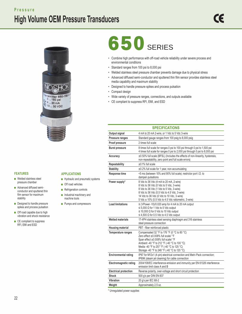
• Combine high performance with off-road vehicle reliability under severe process and environmental conditions• Standard ranges from 100 psi to 8,000 psi• Welded stainless steel pressure chamber prevents damage due to physical stress• Advanced diffused semi-conductor and sputtered thin fi lm sensor provides stainless steel media capability and maximum stability• Designed to handle pressure spikes and process pulsation• Compact design• Wide variety of pressure ranges, connections, and outputs available• CE compliant to suppress RFI, EMI, and ESD
650 650 SERIES
P r e s s u r e
High Volume OEM Pressure Transducers
* Unregulated power supplies
23
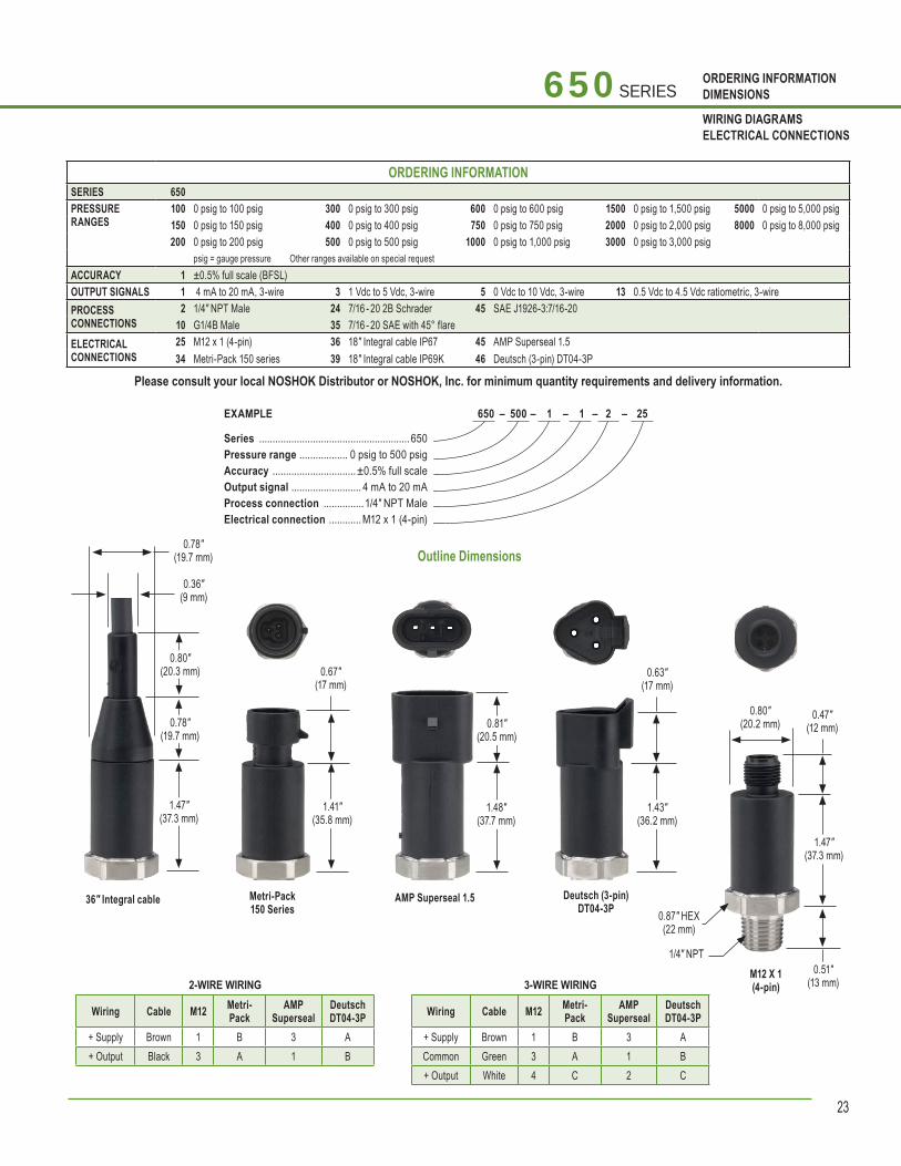
ORDERING INFORMATIONDIMENSIONS
WIRING DIAGRAMSELECTRICAL CONNECTIONS
650 SERIES
Outline Dimensions0.78″
(19.7 mm)
0.36″ (9 mm)
0.80″ (20.3 mm)
0.78″ (19.7 mm)
1.47″ (37.3 mm)
36″ Integral cable Metri-Pack150 Series
0.67″ (17 mm)
1.41″ (35.8 mm)
AMP Superseal 1.5
1.48″ (37.7 mm)
0.81″ (20.5 mm)
Deutsch (3-pin)DT04-3P
0.63″ (17 mm)
1.43" (36.2 mm)
M12 X 1(4-pin)
0.47″ (12 mm)
1.47″ (37.3 mm)
0.51″ (13 mm)
1/4″ NPT
0.87″ HEX(22 mm)
2-WIRE WIRING
Wiring Cable M12 Metri-Pack
AMPSuperseal
DeutschDT04-3P
+ Supply Brown 1 B 3 A+ Output Black 3 A 1 B
3-WIRE WIRING
Wiring Cable M12 Metri-Pack
AMPSuperseal
DeutschDT04-3P
+ Supply Brown 1 B 3 ACommon Green 3 A 1 B+ Output White 4 C 2 C
650 – 500 – 1 – 1 – 2 – 25 EXAMPLE
Series ........................................................ 650Pressure range .................. 0 psig to 500 psigAccuracy ...............................±0.5% full scaleOutput signal .......................... 4 mA to 20 mAProcess connection ...............1/4″ NPT MaleElectrical connection ............M12 x 1 (4-pin)
ORDERING INFORMATIONSERIES 650 PRESSURERANGES
100 0 psig to 100 psig 300 0 psig to 300 psig 600 0 psig to 600 psig 1500 0 psig to 1,500 psig 5000 0 psig to 5,000 psig 150 0 psig to 150 psig 400 0 psig to 400 psig 750 0 psig to 750 psig 2000 0 psig to 2,000 psig 8000 0 psig to 8,000 psig 200 0 psig to 200 psig 500 0 psig to 500 psig 1000 0 psig to 1,000 psig 3000 0 psig to 3,000 psig
psig = gauge pressure Other ranges available on special request ACCURACY 1 ±0.5% full scale (BFSL)OUTPUT SIGNALS 1 4 mA to 20 mA, 3-wire 3 1 Vdc to 5 Vdc, 3-wire 5 0 Vdc to 10 Vdc, 3-wire 13 0.5 Vdc to 4.5 Vdc ratiometric, 3-wirePROCESSCONNECTIONS
2 1/4″ NPT Male 24 7/16 - 20 2B Schrader 45 SAE J1926-3:7/16-2010 G1/4B Male 35 7/16 - 20 SAE with 45° flare
ELECTRICALCONNECTIONS
25 M12 x 1 (4-pin) 36 18″ Integral cable IP67 45 AMP Superseal 1.534 Metri-Pack 150 series 39 18″ Integral cable IP69K 46 Deutsch (3-pin) DT04-3P
Please consult your local NOSHOK Distributor or NOSHOK, Inc. for minimum quantity requirements and delivery information.
0.80″ (20.2 mm)

24
• ATEX-approved II 2G Ex d II C• For dynamic and static measurements• Excellent repeatability• High accuracy and long term stability• Increased accuracy of ±0.125% full scale (BFSL)• Excellent overload protection• Wide variety of pressure ranges• Corrosion-resistant stainless steel design• Welded pressure connection and measuring cell for exceptional shock and vibration resistance• CE compliant to suppress RFI, EMI, and ESD
APPLICATIONS ■ Gas pressure measurement ■ Oil drilling platforms/
pipelines ■ Refineries/petrochemical
industry ■ Borehole monitoring
FEATURES ■ ATEX-approved II 2G Ex d II C ■ For dynamic and static
measurements ■ High accuracy and long term
stability ■ Excellent overload protection ■ Wide variety of pressure
ranges ■ Corrosion-resistant stainless
steel design ■ Excellent repeatability
P r e s s u r e
ATEX-Approved Explosion-Proof Pressure Transmitters
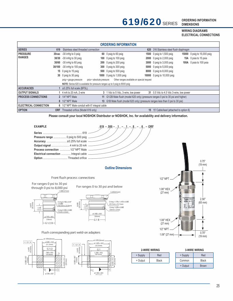
619/620 619/620 SERIES
APPROVED
SPECIFICATIONS Output signals 4 mA to 20 mA, 2-wire; 1 Vdc to 5 Vdc, 3-wire; 0 Vdc to 10 Vdc, 3-wire;
0.5 Vdc to 4.5 Vdc low power, 3-wireAccuracy ±0.25% full scale (BFSL) (Includes the effects of non-linearity, hysteresis,
non-repeatability, zero point and full scale errors)Hysteresis ≤ ±0.1% full scaleRepeatability ≤±0.05% full scaleStability ≤±0.2% full scale for 1 year, non-accumulatingPressure ranges Standard gauge ranges from vacuum to 15,000 psig
Standard absolute ranges from 15 psia to 200 psiaProof pressure 3.5 times full scale for ranges 0 psi to 15 psi through 0 psi to 200 psi
2 times full scale for ranges 0 psi to 300 psi through 0 psi to 10,000 psi1.5 times full scale for 0 psi to 15,000 psi
Burst pressure 5 times full scale for ranges 0 psi to 15 psi through 0 psi to 200 psi3.5 times full scale for ranges 0 psi to 300 psi through 0 psi to 10,000 psi3 times full scale for 0 psi to 15,000 psi
Power supply* 10 Vdc to 30 Vdc (4 mA to 20 mA, 2-wire)6 Vdc to 30 Vdc (1 Vdc to 5 Vdc, 3-wire)6 Vdc to 30 Vdc (0.5 Vdc to 4.5 Vdc, 3-wire)14 Vdc to 30 Vdc (0 Vdc to 10 Vdc, 3-wire)
Load limitations ≤(VPower-10)/0.020 Amp for 4 mA to 20 mA>10,000 Ω for 1 Vdc to 5 Vdc, 3-wire and 0 Vdc to 10 Vdc> 5,000 Ω for 0.5 Vdc to 4.5 Vdc
Response time ≤1 ms (between 10% and 90% full scale)Durability >100,000,000 full scale cyclesTemperature ranges Compensated 32 °F to 176 °F (0 °C to 80 °C)
Zero effect is ≤±0.011% full scale / °FSpan effect is ≤±0.011% full scale / °FAmbient -40 °F to 221 °F (-40 °C to 105 °C)Media -40 °F to 221 °F (-40 °C to 105 °C)Storage -40 °F to 221 °F (-40 °C to 105 °C)
Wetted materials Series 619 is 316 stainless steel for ranges up through 0 psi to 300 psi, 316 stainless steel with Elgiloy for ranges 0 psi to 500 psi and higher;Series 620 is 316 stainless steel with NBR o-ring; optional FPM or EPDM o-ring
Housing material 316 stainless steelEnvironmental rating NEMA 4x (IP 67 according to EN 60 529/IEC529)Electromagnetic rating 89/336/EEC emission (class B) and immunity per EN 61326Electrical protection Reverse polarity, over voltage and short circuit protectionShock 1000 g’s according to IEC 60068-2-27Vibration 20 g’s according to IEC 60068-2-63CE Pressure equipment directive 97/23EC; directive ATEX 94/9/EC HF immunity 10 V/mBurst 4 KV Hazardous approval Explosion-proof protection type ATEX; EX d II c T4-T6Weight Approximately 8 oz.* Unregulated power supplies
25
ORDERING INFORMATIONDIMENSIONS
WIRING DIAGRAMSELECTRICAL CONNECTIONS
Outline Dimensions
619/620 SERIES
Flush corresponding port weld-on adapters
O,1 A
1.61� (41mm)
.
(33.5mm)
. .(21.3mm)
ø1.18�±.003(30mm)ø.71�±.003
(18mm)
O-ring 1.17�x 1.41�x 0.08�(29.7mmx 35.7mm)
O-ring 1.02�x 0.08�(26mmx 2mm)
1.06� (27mm)
O-ring 0.73�x 0.94"x 0.08�(18.5mmx 23.9mm)
O-ring 0.59�x 0.08�(15mmx 2mm)
G1 B
G1
G1/2 B
G1/2
0.81�
(20.
5mm
)
0.39�(10mm)
0.81�
(20.
5mm
)
0.39�(10mm)
.76�±.003(19.4mm)
2 ±
A A
0.59�
±.0
07(1
5mm
)
0.59�
±.0
0 7(1
5mm
)
0 .81�
±.0
1 2(2
0.5m
m)
0.4 1�
(10.
5mm
)
TO,1 A
0.41�
(10.
5mm
)
T
x
x x
x
Front flush process connections
For ranges 0 to 30 psi and belowFor ranges 0 psi to 30 psithrough 0 psi to 8,000 psi
ø.7 � .007(18 2 )
ø1 97� (50mm)
ø 84�± 007ø1.97� (50mm)
ø1.32�±.007
1.20�±.003(30.5mm)
ø1.19�±.003(301mm)
0.81�
±.0
12(2
0.5m
m)
2-WIRE WIRING+ Supply Red+ Output Black
3-WIRE WIRING+ Supply RedCommon Black+ Output Brown
0.75″ (19 mm)
2.56″ (65 mm)
0.75″ (19 mm)
1/2″ NPT
1.06″ HEX(27 mm)
1.06″ (27 mm)
1.06″ HEX(27 mm)
1/2″ NPT
619 – 500 – 1 – 1 – 8 – 6 – ORF EXAMPLE
Series ........................................................ 619Pressure range .................. 0 psig to 500 psigAccuracy .............................±0.25% full scaleOutput signal .......................... 4 mA to 20 mAProcess connection ...............1/2″ NPT MaleElectrical connection .............. Integral cableOption ................................... Threaded orifice
ORDERING INFORMATIONSERIES 619 Stainless steel threaded connection 620 316 Stainless steel flush diaphragm PRESSURERANGES
30vac -30 inHg to 0 psig 60 0 psig to 60 psig 1 500 0 psig to 1,500 psig 15000 0 psig to 15,000 psig 30/30 -30 inHg to 30 psig 100 0 psig to 100 psig 2000 0 psig to 2,000 psig 15A 0 psia to 15 psia 30/60 -30 inHg to 60 psig 200 0 psig to 200 psig 3000 0 psig to 3,000 psig 100A 0 psia to 100 psia
30/100 -30 inHg to 100 psig 300 0 psig to 300 psig 5000 0 psig to 5,000 psig 15 0 psig to 15 psig 500 0 psig to 500 psig 8000 0 psig to 8,000 psig30 0 psig to 30 psig 1000 0 psig to 1,000 psig 10000 0 psig to 10,000 psig
psig = gauge pressure psia = absolute pressure Other ranges available on special request NOTE: Series 620 is available for pressure ranges up to 0 psig to 8000 psig
ACCURACIES 1 ±0.25% full scale (BFSL)OUTPUT SIGNALS 1 4 mA to 20 mA, 2-wire 3 1 Vdc to 5 Vdc, 3-wire, low power 31 0.5 Vdc to 4.5 Vdc 3-wire, low powerPROCESS CONNECTIONS 2 1/4″ NPT Male 11 G1/2B Male flush (model 620 only) (pressure ranges 0 psi to 30 psi and higher)
8 1/2″ NPT Male 13 G1B Male flush (model 620 only) (pressure ranges less than 0 psi to 30 psi) ELECTRICAL CONNECTION 6 1/2″ NPT Male conduit with 6′ integral cableOPTION ORF Threaded orifice (Model 619 only) 15 15′ Cable/lead (attached to option 6)
Please consult your local NOSHOK Distributor or NOSHOK, Inc. for availability and delivery information.
26
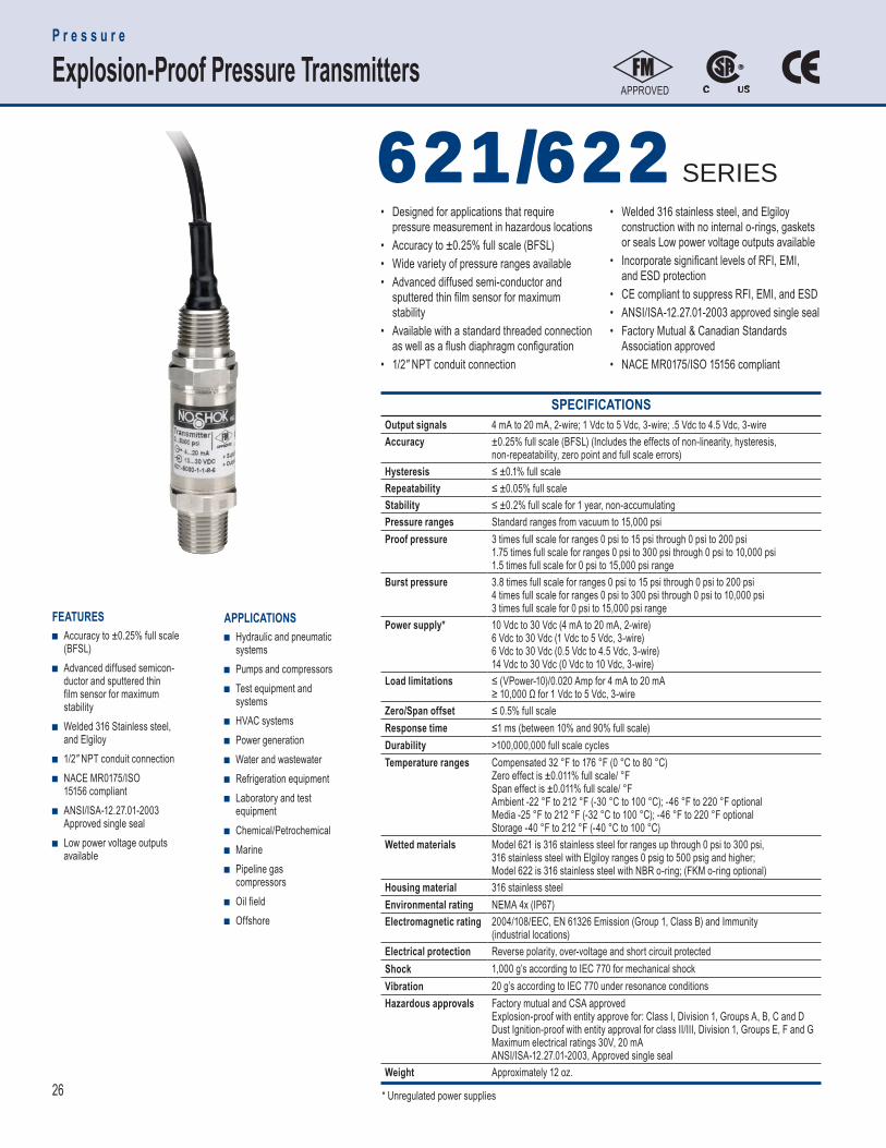
SPECIFICATIONS Output signals 4 mA to 20 mA, 2-wire; 1 Vdc to 5 Vdc, 3-wire; .5 Vdc to 4.5 Vdc, 3-wireAccuracy ±0.25% full scale (BFSL) (Includes the effects of non-linearity, hysteresis,
non-repeatability, zero point and full scale errors)Hysteresis ≤ ±0.1% full scaleRepeatability ≤ ±0.05% full scaleStability ≤ ±0.2% full scale for 1 year, non-accumulatingPressure ranges Standard ranges from vacuum to 15,000 psiProof pressure 3 times full scale for ranges 0 psi to 15 psi through 0 psi to 200 psi
1.75 times full scale for ranges 0 psi to 300 psi through 0 psi to 10,000 psi1.5 times full scale for 0 psi to 15,000 psi range
Burst pressure 3.8 times full scale for ranges 0 psi to 15 psi through 0 psi to 200 psi4 times full scale for ranges 0 psi to 300 psi through 0 psi to 10,000 psi3 times full scale for 0 psi to 15,000 psi range
Power supply* 10 Vdc to 30 Vdc (4 mA to 20 mA, 2-wire)6 Vdc to 30 Vdc (1 Vdc to 5 Vdc, 3-wire)6 Vdc to 30 Vdc (0.5 Vdc to 4.5 Vdc, 3-wire)14 Vdc to 30 Vdc (0 Vdc to 10 Vdc, 3-wire)
Load limitations ≤ (VPower-10)/0.020 Amp for 4 mA to 20 mA≥ 10,000 Ω for 1 Vdc to 5 Vdc, 3-wire
Zero/Span offset ≤ 0.5% full scaleResponse time ≤1 ms (between 10% and 90% full scale)Durability >100,000,000 full scale cyclesTemperature ranges Compensated 32 °F to 176 °F (0 °C to 80 °C)
Zero effect is ±0.011% full scale/ °F Span effect is ±0.011% full scale/ °FAmbient -22 °F to 212 °F (-30 °C to 100 °C); -46 °F to 220 °F optionalMedia -25 °F to 212 °F (-32 °C to 100 °C); -46 °F to 220 °F optionalStorage -40 °F to 212 °F (-40 °C to 100 °C)
Wetted materials Model 621 is 316 stainless steel for ranges up through 0 psi to 300 psi, 316 stainless steel with Elgiloy ranges 0 psig to 500 psig and higher; Model 622 is 316 stainless steel with NBR o-ring; (FKM o-ring optional)
Housing material 316 stainless steelEnvironmental rating NEMA 4x (IP67)Electromagnetic rating 2004/108/EEC, EN 61326 Emission (Group 1, Class B) and Immunity
(industrial locations)Electrical protection Reverse polarity, over-voltage and short circuit protectedShock 1,000 g’s according to IEC 770 for mechanical shockVibration 20 g’s according to IEC 770 under resonance conditionsHazardous approvals Factory mutual and CSA approved
Explosion-proof with entity approve for: Class I, Division 1, Groups A, B, C and DDust Ignition-proof with entity approval for class II/III, Division 1, Groups E, F and GMaximum electrical ratings 30V, 20 mAANSI/ISA-12.27.01-2003, Approved single seal
Weight Approximately 12 oz.
APPLICATIONS ■ Hydraulic and pneumatic
systems ■ Pumps and compressors ■ Test equipment and
systems ■ HVAC systems ■ Power generation ■ Water and wastewater ■ Refrigeration equipment ■ Laboratory and test
equipment ■ Chemical/Petrochemical ■ Marine ■ Pipeline gas
compressors ■ Oil field ■ Offshore
FEATURES ■ Accuracy to ±0.25% full scale
(BFSL) ■ Advanced diffused semicon-
ductor and sputtered thin film sensor for maximum stability
■ Welded 316 Stainless steel, and Elgiloy
■ 1/2″ NPT conduit connection ■ NACE MR0175/ISO
15156 compliant ■ ANSI/ISA-12.27.01-2003
Approved single seal ■ Low power voltage outputs
available
• Designed for applications that require pressure measurement in hazardous locations• Accuracy to ±0.25% full scale (BFSL)• Wide variety of pressure ranges available• Advanced diffused semi-conductor and sputtered thin fi lm sensor for maximum stability• Available with a standard threaded connection as well as a fl ush diaphragm confi guration• 1/2" NPT conduit connection
• Welded 316 stainless steel, and Elgiloy construction with no internal o-rings, gaskets or seals Low power voltage outputs available• Incorporate signifi cant levels of RFI, EMI, and ESD protection• CE compliant to suppress RFI, EMI, and ESD• ANSI/ISA-12.27.01-2003 approved single seal• Factory Mutual & Canadian Standards Association approved• NACE MR0175/ISO 15156 compliant
P r e s s u r e
Explosion-Proof Pressure TransmittersAPPROVED
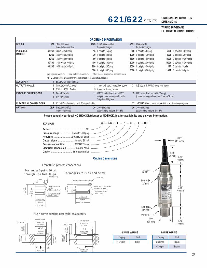
621/622621/622 SERIES
* Unregulated power supplies
27
ORDERING INFORMATIONDIMENSIONS
WIRING DIAGRAMSELECTRICAL CONNECTIONS
Outline Dimensions
621/622 SERIES
Flush corresponding port weld-on adapters
O,1 A
1.61� (41mm)
.
(33.5mm)
. .(21.3mm)
ø1.18�±.003(30mm)ø.71�±.003
(18mm)
O-ring 1.17�x 1.41�x 0.08�(29.7mmx 35.7mm)
O-ring 1.02�x 0.08�(26mmx 2mm)
1.06� (27mm)
O-ring 0.73�x 0.94"x 0.08�(18.5mmx 23.9mm)
O-ring 0.59�x 0.08�(15mmx 2mm)
G1 B
G1
G1/2 B
G1/2
0.81�
(20.
5mm
)
0.39�(10mm)
0.81�
(20.
5mm
)
0.39�(10mm)
.76�±.003(19.4mm)
2 ±
A A
0.59�
±.0
07(1
5mm
)
0.59�
±.0
0 7(1
5mm
)
0 .81�
±.0
1 2(2
0.5m
m)
0.4 1�
(10.
5mm
)
TO,1 A
0.41�
(10.
5mm
)
T
x
x x
x
Front flush process connections
For ranges 0 to 30 psi and belowFor ranges 0 psi to 30 psithrough 0 psi to 8,000 psi
ø.7 � .007(18 2mm)
ø1 97� (50mm)
ø 84�± 007ø1.97� (50mm)
ø1.32�±.007
1.20�±.003(30.5mm)
ø1.19�±.003(30.1mm)
0.81�
±.0
12(2
0.5m
m)
2-WIRE WIRING+ Supply Red+ Output Black
3-WIRE WIRING+ Supply RedCommon Black+ Output Brown
0.75″ (19 mm)
2.56″ (65 mm)
0.75″ (19 mm)
1/2″ NPT
1.06″ HEX(27 mm)
1.06″ (27 mm)
1.06″ HEX(27 mm)
1/2″ NPT
1.42″ (36 mm)
0.61″ (15.5 mm)
621 – 500 – 1 – 1 – 8 – 6 – ORF EXAMPLE
Series ........................................................ 621Pressure range .................. 0 psig to 500 psigAccuracy .............................±0.25% full scaleOutput signal .......................... 4 mA to 20 mAProcess connection ...............1/2″ NPT MaleElectrical connection .............. Integral cableOption ................................... Threaded orifice
ORDERING INFORMATIONSERIES 621 Stainless steel
threaded connection622S 316 Stainless steel
flush diaphragm622H Hastelloy C
fl ush diaphragm PRESSURERANGES
30vac -30 inHg to 0 psig 15 0 psig to 15 psig 500 0 psig to 500 psig 6000 0 psig to 6,000 psig 30/30 -30 inHg to 30 psig 30 0 psig to 30 psig 1 000 0 psig to 1,000 psig 8000 0 psig to 8,000 psig 30/60 -30 inHg to 60 psig 60 0 psig to 60 psig 1500 0 psig to 1,500 psig 10000 0 psig to 10,000 psig
30/100 -30 inHg to 100 psig 100 0 psig to 100 psig 2000 0 psig to 2,000 psig 15000 0 psig to 15,000 psig30/200 -30 inHg to 200 psig 200 0 psig to 200 psig 3000 0 psig to 3,000 psig 15A 0 psia to 15 psia
300 0 psig to 300 psig 5000 0 psig to 5,000 psig 100A 0 psia to 100 psiapsig = gauge pressure psia = absolute pressure Other ranges available on special request NOTE: Series 622 is available for pressure ranges up to 0 psig to 8,000 psig
ACCURACY 1 ±0.25% full scale (BFSL)OUTPUT SIGNALS 1 4 mA to 20 mA, 2-wire 3 1 Vdc to 5 Vdc, 3-wire, low power 31 0.5 Vdc to 4.5 Vdc 3-wire, low power
2 0 Vdc to 5 Vdc, 3-wire 5 0 Vdc to 10 Vdc, 3-wirePROCESS CONNECTIONS 2 1/4″ NPT male 11 G1/2B male flush (model 622
only) (pressure ranges 0 psi to 30 psi and higher)
13 G1B male flush (model 622 only)(pressure ranges less than 0 psi to 30 psi)8 1/2" NPT male
ELECTRICAL CONNECTIONS 6 1/2″ NPT male conduit with 6' integral cable 37 1/2″ NPT Male conduit with 6' flying leads with epoxy sealOPTIONS ORF Threaded Orifice
(model 621 only)20 20′ cable/lead
(attached to options 6 or 37)30 30′ cable/lead
(attached to options 6 or 37)
Please consult your local NOSHOK Distributor or NOSHOK, Inc. for availability and delivery information.
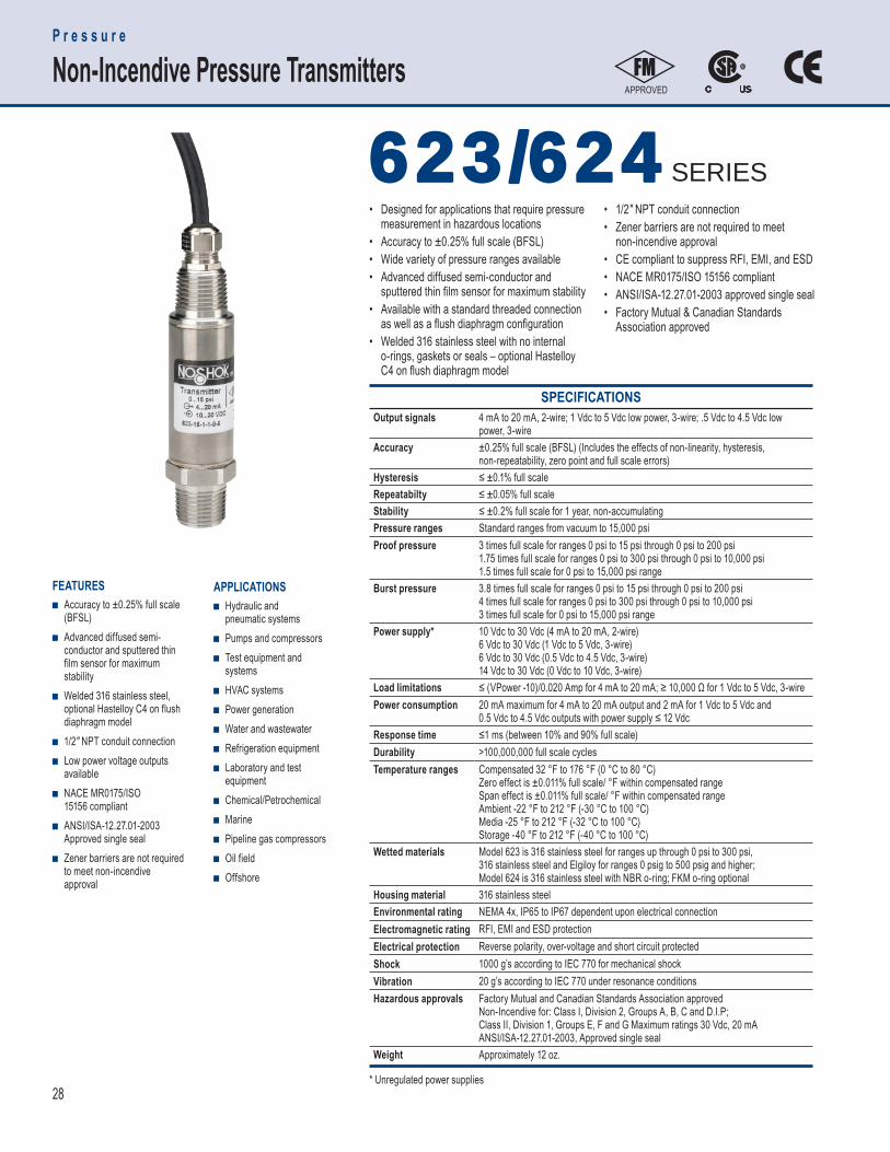
28
APPROVED
SPECIFICATIONS Output signals 4 mA to 20 mA, 2-wire; 1 Vdc to 5 Vdc low power, 3-wire; .5 Vdc to 4.5 Vdc low
power, 3-wireAccuracy ±0.25% full scale (BFSL) (Includes the effects of non-linearity, hysteresis,
non-repeatability, zero point and full scale errors)Hysteresis ≤ ±0.1% full scaleRepeatabilty ≤ ±0.05% full scale Stability ≤ ±0.2% full scale for 1 year, non-accumulatingPressure ranges Standard ranges from vacuum to 15,000 psiProof pressure 3 times full scale for ranges 0 psi to 15 psi through 0 psi to 200 psi
1.75 times full scale for ranges 0 psi to 300 psi through 0 psi to 10,000 psi1.5 times full scale for 0 psi to 15,000 psi range
Burst pressure 3.8 times full scale for ranges 0 psi to 15 psi through 0 psi to 200 psi4 times full scale for ranges 0 psi to 300 psi through 0 psi to 10,000 psi3 times full scale for 0 psi to 15,000 psi range
Power supply* 10 Vdc to 30 Vdc (4 mA to 20 mA, 2-wire)6 Vdc to 30 Vdc (1 Vdc to 5 Vdc, 3-wire)6 Vdc to 30 Vdc (0.5 Vdc to 4.5 Vdc, 3-wire)14 Vdc to 30 Vdc (0 Vdc to 10 Vdc, 3-wire)
Load limitations ≤ (VPower -10)/0.020 Amp for 4 mA to 20 mA; ≥ 10,000 Ω for 1 Vdc to 5 Vdc, 3-wirePower consumption 20 mA maximum for 4 mA to 20 mA output and 2 mA for 1 Vdc to 5 Vdc and
0.5 Vdc to 4.5 Vdc outputs with power supply ≤ 12 VdcResponse time ≤1 ms (between 10% and 90% full scale)Durability >100,000,000 full scale cyclesTemperature ranges Compensated 32 °F to 176 °F (0 °C to 80 °C)
Zero effect is ±0.011% full scale/ °F within compensated rangeSpan effect is ±0.011% full scale/ °F within compensated rangeAmbient -22 °F to 212 °F (-30 °C to 100 °C)Media -25 °F to 212 °F (-32 °C to 100 °C)Storage -40 °F to 212 °F (-40 °C to 100 °C)
Wetted materials Model 623 is 316 stainless steel for ranges up through 0 psi to 300 psi,316 stainless steel and Elgiloy for ranges 0 psig to 500 psig and higher;Model 624 is 316 stainless steel with NBR o-ring; FKM o-ring optional
Housing material 316 stainless steel Environmental rating NEMA 4x, IP65 to IP67 dependent upon electrical connection Electromagnetic rating RFI, EMI and ESD protection Electrical protection Reverse polarity, over-voltage and short circuit protectedShock 1000 g’s according to IEC 770 for mechanical shockVibration 20 g’s according to IEC 770 under resonance conditionsHazardous approvals Factory Mutual and Canadian Standards Association approved
Non-Incendive for: Class I, Division 2, Groups A, B, C and D.I.P;Class II, Division 1, Groups E, F and G Maximum ratings 30 Vdc, 20 mAANSI/ISA-12.27.01-2003, Approved single seal
Weight Approximately 12 oz.
APPLICATIONS ■ H ydraulic and
pneumatic systems ■ Pumps and compressors ■ Test equipment and
systems ■ HVAC systems ■ Power generation ■ Water and wastewater ■ Refrigeration equipment ■ Laboratory and test
equipment ■ Chemical/Petrochemical ■ Marine ■ Pipeline gas compressors ■ Oil field ■ Offshore
FEATURES ■ A ccuracy to ±0.25% full scale
(BFSL) ■ Advanced diffused semi-
conductor and sputtered thin film sensor for maximum stability
■ Welded 316 stainless steel, optional Hastelloy C4 on flush diaphragm model
■ 1/2″ NPT conduit connection ■ Low power voltage outputs
available ■ NACE MR0175/ISO
15156 compliant ■ ANSI/ISA-12.27.01-2003
Approved single seal ■ Zener barriers are not required
to meet non-incendive approval
623/624 623/624 SERIES
P r e s s u r e
Non-Incendive Pressure Transmitters
* Unregulated power supplies
• Designed for applications that require pressure measurement in hazardous locations• Accuracy to ±0.25% full scale (BFSL)• Wide variety of pressure ranges available• Advanced diffused semi-conductor and sputtered thin fi lm sensor for maximum stability• Available with a standard threaded connection as well as a fl ush diaphragm confi guration• Welded 316 stainless steel with no internal o-rings, gaskets or seals – optional Hastelloy C4 on fl ush diaphragm model
• 1/2" NPT conduit connection• Zener barriers are not required to meet non-incendive approval• CE compliant to suppress RFI, EMI, and ESD• NACE MR0175/ISO 15156 compliant• ANSI/ISA-12.27.01-2003 approved single seal• Factory Mutual & Canadian Standards Association approved
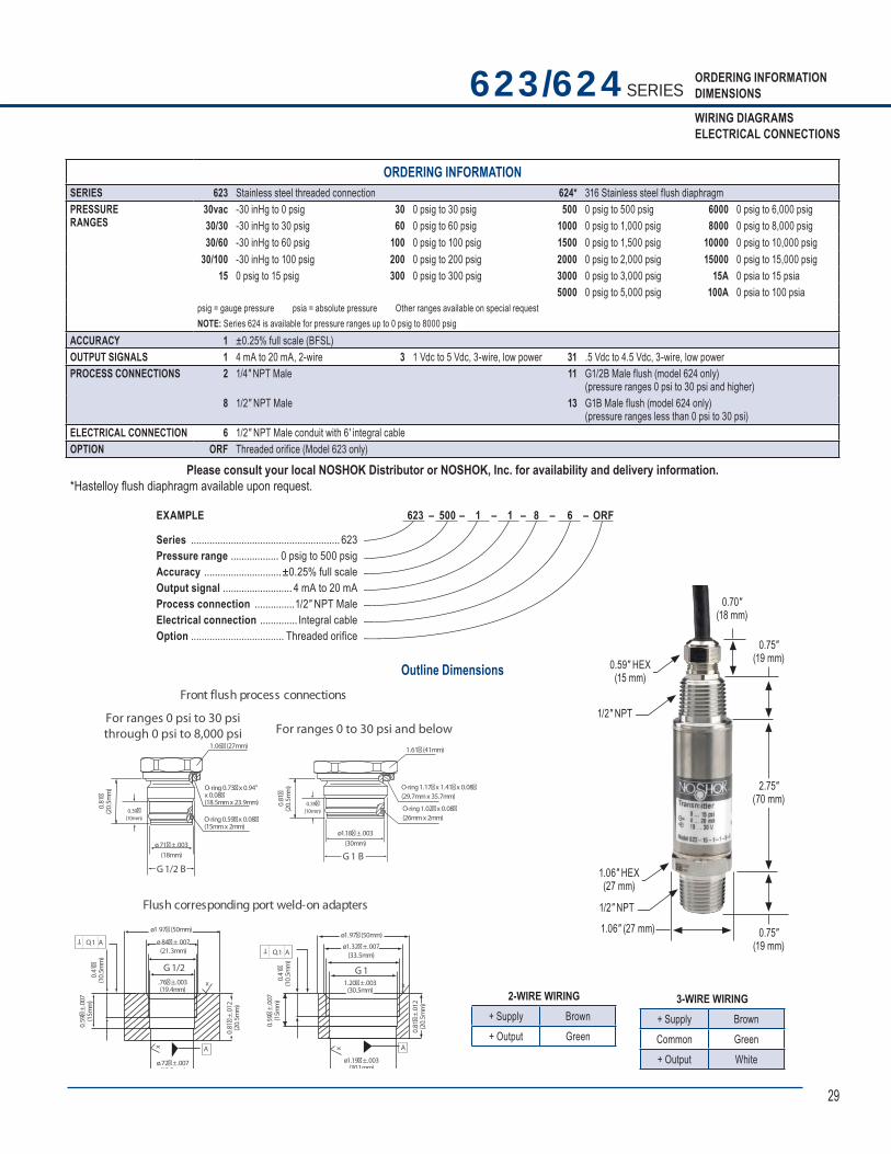
29
ORDERING INFORMATIONDIMENSIONS
WIRING DIAGRAMSELECTRICAL CONNECTIONS
Outline Dimensions
623/624 SERIES
Flush corresponding port weld-on adapters
O,1 A
1.61� (41mm)
.
(33.5mm)
. .(21.3mm)
ø1.18�±.003(30mm)ø.71�±.003
(18mm)
O-ring 1.17�x 1.41�x 0.08�(29.7mmx 35.7mm)
O-ring 1.02�x 0.08�(26mmx 2mm)
1.06� (27mm)
O-ring 0.73�x 0.94"x 0.08�(18.5mmx 23.9mm)
O-ring 0.59�x 0.08�(15mmx 2mm)
G1 B
G1
G1/2 B
G1/2
0.81�
(20.
5mm
)
0.39�(10mm)
0.81�
(20.
5mm
)
0.39�(10mm)
.76�±.003(19.4mm)
2 ±
A A
0.59�
±.0
07(1
5mm
)
0.59�
±.0
0 7(1
5mm
)
0 .81�
±.0
1 2(2
0.5m
m)
0.4 1�
(10.
5mm
)
TO,1 A
0.41�
(10.
5mm
)
T
x
x x
x
Front flush process connections
For ranges 0 to 30 psi and belowFor ranges 0 psi to 30 psithrough 0 psi to 8,000 psi
ø.7 � .007(18 2 )
ø1 97� (50mm)
ø 84�± 007ø1.97� (50mm)
ø1.32�±.007
1.20�±.003(30.5mm)
ø1.19�±.003(301mm)
0.81�
±.0
12(2
0.5m
m)
2-WIRE WIRING+ Supply Brown+ Output Green
3-WIRE WIRING+ Supply BrownCommon Green+ Output White
0.75″ (19 mm)
2.75″ (70 mm)
0.75″ (19 mm)
1/2″ NPT
1.06″ HEX(27 mm)
1.06″ (27 mm)
0.59″ HEX(15 mm)
1/2″ NPT
0.70″ (18 mm)
EXAMPLE
Series ........................................................ 623Pressure range .................. 0 psig to 500 psigAccuracy .............................±0.25% full scaleOutput signal .......................... 4 mA to 20 mAProcess connection ...............1/2″ NPT MaleElectrical connection .............. Integral cableOption ................................... Threaded orifice
623 – 500 – 1 – 1 – 8 – 6 – ORF
ORDERING INFORMATIONSERIES 623 Stainless steel threaded connection 624* 316 Stainless steel flush diaphragmPRESSURERANGES
30vac -30 inHg to 0 psig 30 0 psig to 30 psig 500 0 psig to 500 psig 6000 0 psig to 6,000 psig 30/30 -30 inHg to 30 psig 60 0 psig to 60 psig 1000 0 psig to 1,000 psig 8000 0 psig to 8,000 psig 30/60 -30 inHg to 60 psig 100 0 psig to 100 psig 1500 0 psig to 1,500 psig 10000 0 psig to 10,000 psig
30/100 -30 inHg to 100 psig 200 0 psig to 200 psig 2000 0 psig to 2,000 psig 15000 0 psig to 15,000 psig15 0 psig to 15 psig 300 0 psig to 300 psig 3000 0 psig to 3,000 psig 15A 0 psia to 15 psia
5000 0 psig to 5,000 psig 100A 0 psia to 100 psiapsig = gauge pressure psia = absolute pressure Other ranges available on special request NOTE: Series 624 is available for pressure ranges up to 0 psig to 8000 psig
ACCURACY 1 ±0.25% full scale (BFSL)OUTPUT SIGNALS 1 4 mA to 20 mA, 2-wire 3 1 Vdc to 5 Vdc, 3-wire, low power 31 .5 Vdc to 4.5 Vdc, 3-wire, low powerPROCESS CONNECTIONS 2 1/4″ NPT Male 11 G1/2B Male flush (model 624 only)
(pressure ranges 0 psi to 30 psi and higher)8 1/2″ NPT Male 13 G1B Male flush (model 624 only)
(pressure ranges less than 0 psi to 30 psi) ELECTRICAL CONNECTION 6 1/2″ NPT Male conduit with 6' integral cableOPTION ORF Threaded orifice (Model 623 only)
Please consult your local NOSHOK Distributor or NOSHOK, Inc. for availability and delivery information.*Hastelloy fl ush diaphragm available upon request.
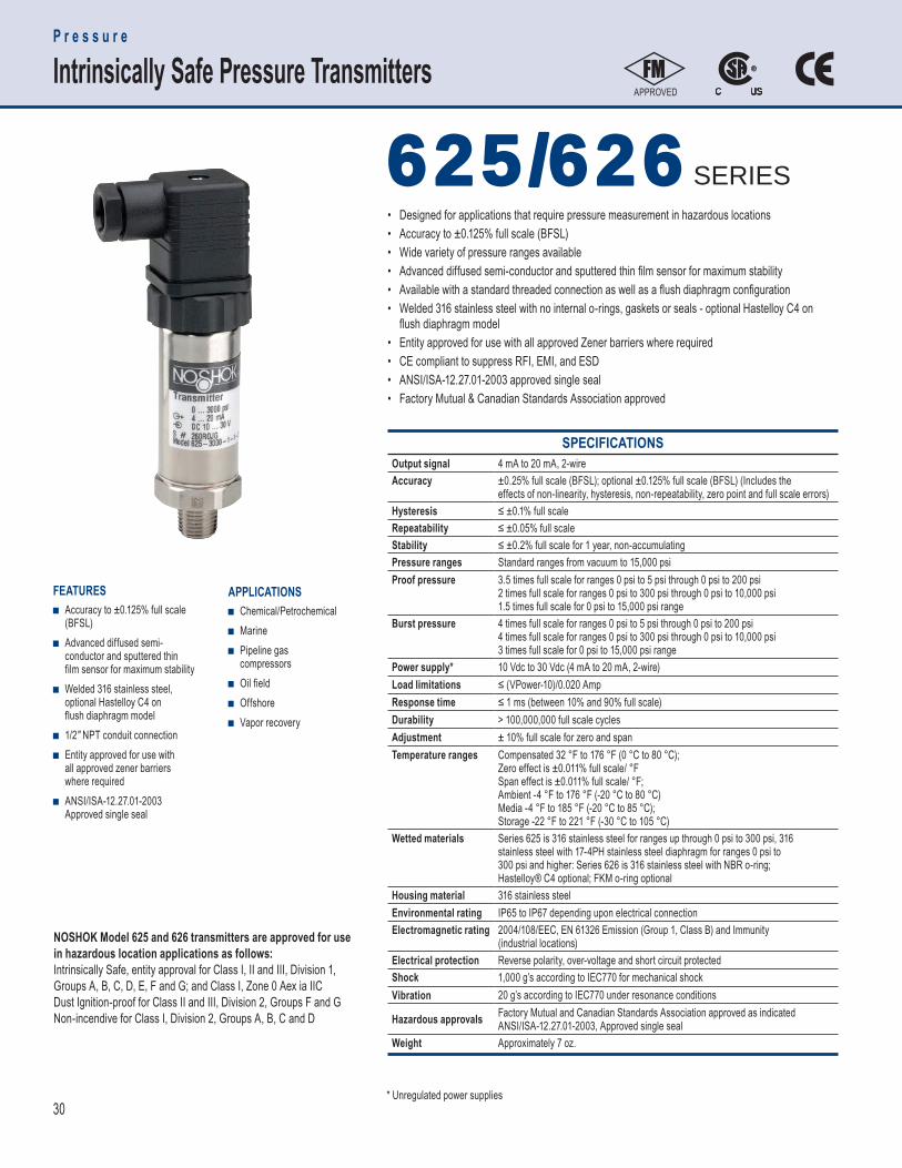
30
SPECIFICATIONS Output signal 4 mA to 20 mA, 2-wireAccuracy ±0.25% full scale (BFSL); optional ±0.125% full scale (BFSL) (Includes the
effects of non-linearity, hysteresis, non-repeatability, zero point and full scale errors)Hysteresis ≤ ±0.1% full scaleRepeatability ≤ ±0.05% full scaleStability ≤ ±0.2% full scale for 1 year, non-accumulatingPressure ranges Standard ranges from vacuum to 15,000 psiProof pressure 3.5 times full scale for ranges 0 psi to 5 psi through 0 psi to 200 psi
2 times full scale for ranges 0 psi to 300 psi through 0 psi to 10,000 psi1.5 times full scale for 0 psi to 15,000 psi range
Burst pressure 4 times full scale for ranges 0 psi to 5 psi through 0 psi to 200 psi4 times full scale for ranges 0 psi to 300 psi through 0 psi to 10,000 psi3 times full scale for 0 psi to 15,000 psi range
Power supply* 10 Vdc to 30 Vdc (4 mA to 20 mA, 2-wire)Load limitations ≤ (VPower-10)/0.020 AmpResponse time ≤ 1 ms (between 10% and 90% full scale)Durability > 100,000,000 full scale cyclesAdjustment ± 10% full scale for zero and spanTemperature ranges Compensated 32 °F to 176 °F (0 °C to 80 °C);
Zero effect is ±0.011% full scale/ °FSpan effect is ±0.011% full scale/ °F; Ambient -4 °F to 176 °F (-20 °C to 80 °C)Media -4 °F to 185 °F (-20 °C to 85 °C); Storage -22 °F to 221 °F (-30 °C to 105 °C)
Wetted materials Series 625 is 316 stainless steel for ranges up through 0 psi to 300 psi, 316stainless steel with 17-4PH stainless steel diaphragm for ranges 0 psi to300 psi and higher: Series 626 is 316 stainless steel with NBR o-ring; Hastelloy® C4 optional; FKM o-ring optional
Housing material 316 stainless steelEnvironmental rating IP65 to IP67 depending upon electrical connectionElectromagnetic rating 2004/108/EEC, EN 61326 Emission (Group 1, Class B) and Immunity
(industrial locations)Electrical protection Reverse polarity, over-voltage and short circuit protectedShock 1,000 g’s according to IEC770 for mechanical shockVibration 20 g’s according to IEC770 under resonance conditions
Hazardous approvals Factory Mutual and Canadian Standards Association approved as indicatedANSI/ISA-12.27.01-2003, Approved single seal
Weight Approximately 7 oz.
APPLICATIONS ■ Chemical/Petrochemical ■ Marine ■ Pipeline gas
compressors ■ Oil field ■ Offshore ■ Vapor recovery
FEATURES ■ Accuracy to ±0.125% full scale
(BFSL) ■ Advanced diffused semi-
conductor and sputtered thin film sensor for maximum stability
■ Welded 316 stainless steel, optional Hastelloy C4 on flush diaphragm model
■ 1/2″ NPT conduit connection ■ Entity approved for use with
all approved zener barriers where required
■ ANSI/ISA-12.27.01-2003 Approved single seal
• Designed for applications that require pressure measurement in hazardous locations• Accuracy to ±0.125% full scale (BFSL)• Wide variety of pressure ranges available• Advanced diffused semi-conductor and sputtered thin fi lm sensor for maximum stability• Available with a standard threaded connection as well as a fl ush diaphragm confi guration• Welded 316 stainless steel with no internal o-rings, gaskets or seals - optional Hastelloy C4 on fl ush diaphragm model• Entity approved for use with all approved Zener barriers where required• CE compliant to suppress RFI, EMI, and ESD• ANSI/ISA-12.27.01-2003 approved single seal• Factory Mutual & Canadian Standards Association approved
625/626 625/626 SERIES
APPROVED
P r e s s u r e
Intrinsically Safe Pressure Transmitters
NOSHOK Model 625 and 626 transmitters are approved for use in hazardous location applications as follows:Intrinsically Safe, entity approval for Class I, II and III, Division 1, Groups A, B, C, D, E, F and G; and Class I, Zone 0 Aex ia IICDust Ignition-proof for Class II and III, Division 2, Groups F and GNon-incendive for Class I, Division 2, Groups A, B, C and D
* Unregulated power supplies
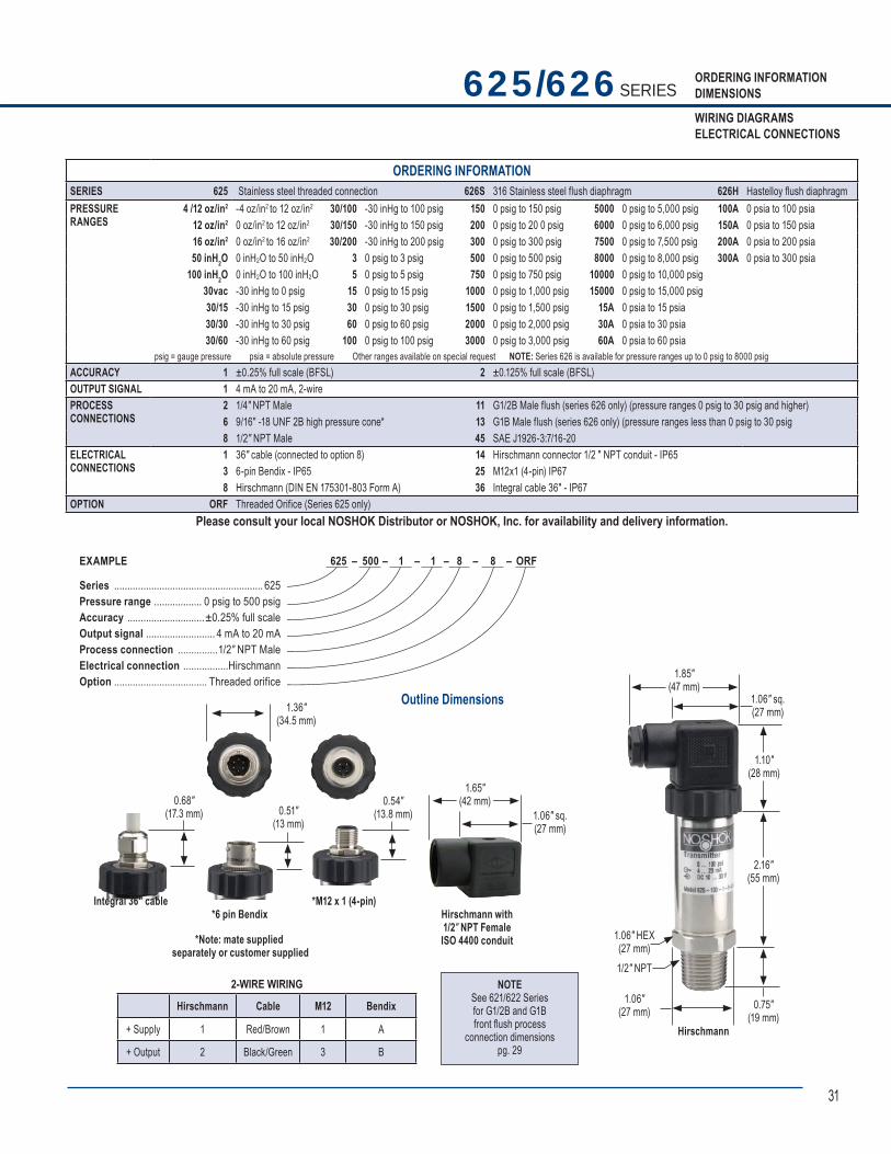
31
ORDERING INFORMATIONDIMENSIONS
WIRING DIAGRAMSELECTRICAL CONNECTIONS
Outline Dimensions
625/626 SERIES
2-WIRE WIRING
Hirschmann Cable M12 Bendix
+ Supply 1 Red/Brown 1 A
+ Output 2 Black/Green 3 B
NOTESee 621/622 Seriesfor G1/2B and G1Bfront fl ush process
connection dimensionspg. 29
Hirschmann
1.06"(27 mm)
1.85"(47 mm)
1.06" sq.(27 mm)
1.10"(28 mm)
2.16"(55 mm)
0.75"(19 mm)
1/2" NPT
1.06" HEX(27 mm)
1.36″(34.5 mm)
Integral 36″ cable
0.68"(17.3 mm)
*6 pin Bendix
0.51"(13 mm)
*M12 x 1 (4-pin)
0.54"(13.8 mm)
Hirschmann with1/2″ NPT FemaleISO 4400 conduit
1.65"(42 mm)
1.06" sq.(27 mm)
*Note: mate supplied separately or customer supplied
625 – 500 – 1 – 1 – 8 – 8 – ORF EXAMPLE
Series ........................................................ 625Pressure range .................. 0 psig to 500 psigAccuracy .............................±0.25% full scaleOutput signal .......................... 4 mA to 20 mAProcess connection ...............1/2″ NPT MaleElectrical connection .................HirschmannOption ................................... Threaded orifice
ORDERING INFORMATIONSERIES 625 Stainless steel threaded connection 626S 316 Stainless steel flush diaphragm 626H Hastelloy fl ush diaphragm PRESSURE RANGES
4 /12 oz/in2 -4 oz/in2 to 12 oz/in2 30/100 -30 inHg to 100 psig 150 0 psig to 150 psig 5000 0 psig to 5,000 psig 100A 0 psia to 100 psia12 oz/in2 0 oz/in2 to 12 oz/in2 30/150 -30 inHg to 150 psig 200 0 psig to 20 0 psig 6000 0 psig to 6,000 psig 150A 0 psia to 150 psia16 oz/in2 0 oz/in2 to 16 oz/in2 30/200 -30 inHg to 200 psig 300 0 psig to 300 psig 7500 0 psig to 7,500 psig 200A 0 psia to 200 psia50 inH2O 0 inH2O to 50 inH2O 3 0 psig to 3 psig 500 0 psig to 500 psig 8000 0 psig to 8,000 psig 300A 0 psia to 300 psia
100 inH2O 0 inH2O to 100 inH2O 5 0 psig to 5 psig 750 0 psig to 750 psig 10000 0 psig to 10,000 psig 30vac -30 inHg to 0 psig 15 0 psig to 15 psig 1000 0 psig to 1,000 psig 15000 0 psig to 15,000 psig30/15 -30 inHg to 15 psig 30 0 psig to 30 psig 1500 0 psig to 1,500 psig 15A 0 psia to 15 psia 30/30 -30 inHg to 30 psig 60 0 psig to 60 psig 2000 0 psig to 2,000 psig 30A 0 psia to 30 psia 30/60 -30 inHg to 60 psig 100 0 psig to 100 psig 3000 0 psig to 3,000 psig 60A 0 psia to 60 psia
psig = gauge pressure psia = absolute pressure Other ranges available on special request NOTE: Series 626 is available for pressure ranges up to 0 psig to 8000 psig ACCURACY 1 ±0.25% full scale (BFSL) 2 ±0.125% full scale (BFSL)OUTPUT SIGNAL 1 4 mA to 20 mA, 2-wirePROCESSCONNECTIONS
2 1/4″ NPT Male 11 G1/2B Male flush (series 626 only) (pressure ranges 0 psig to 30 psig and higher)6 9/16″ -18 UNF 2B high pressure cone* 13 G1B Male flush (series 626 only) (pressure ranges less than 0 psig to 30 psig8 1/2" NPT Male 45 SAE J1926-3:7/16-20
ELECTRICALCONNECTION S
1 36″ cable (connected to option 8) 14 Hirschmann connector 1/2 ″ NPT conduit - IP653 6-pin Bendix - IP65 25 M12x1 (4-pin) IP678 Hirschmann (DIN EN 175301-803 Form A) 36 Integral cable 36″ - IP67
OPTION ORF Threaded Orifice (Series 625 only) Please consult your local NOSHOK Distributor or NOSHOK, Inc. for availability and delivery information.
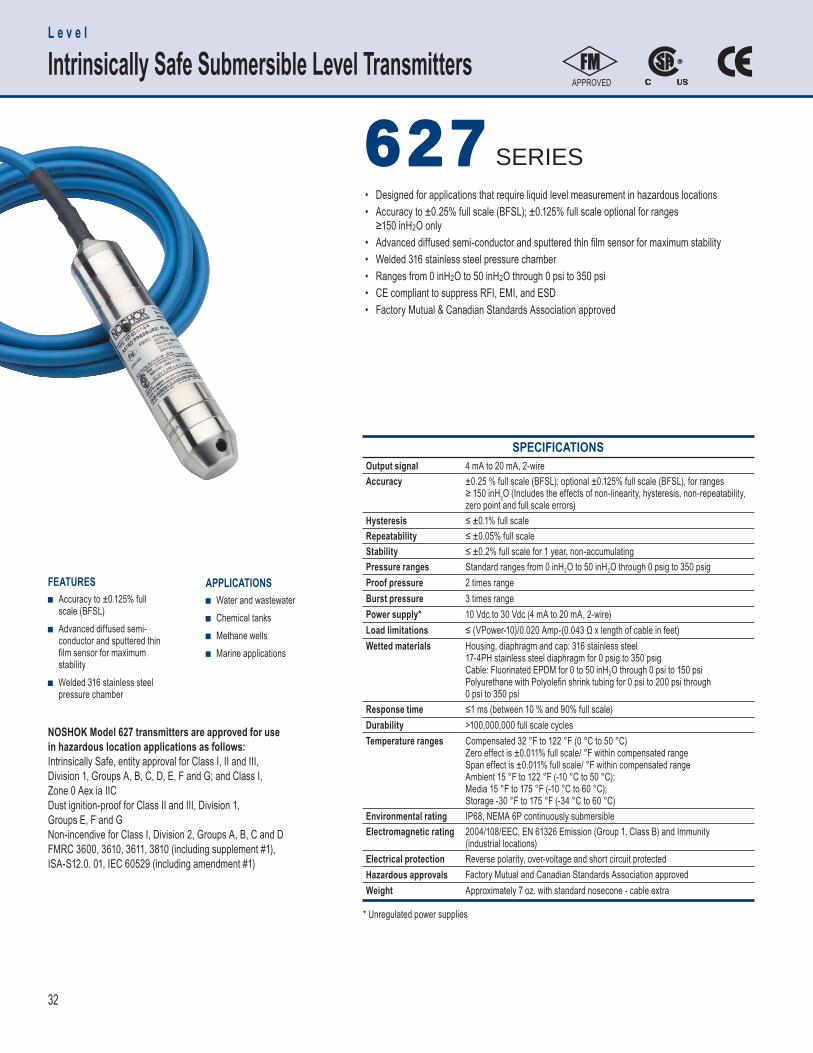
32
FEATURES ■ Accuracy to ±0.125% full
scale (BFSL) ■ Advanced diffused semi-
conductor and sputtered thin film sensor for maximum stability
■ Welded 316 stainless steel pressure chamber
APPLICATIONS ■ Water and wastewater ■ Chemical tanks ■ Methane wells ■ Marine applications
SPECIFICATIONS Output signal 4 mA to 20 mA, 2-wireAccuracy ±0.25 % full scale (BFSL); optional ±0.125% full scale (BFSL), for ranges
≥ 150 inH2O (Includes the effects of non-linearity, hysteresis, non-repeatability, zero point and full scale errors)
Hysteresis ≤ ±0.1% full scaleRepeatability ≤ ±0.05% full scaleStability ≤ ±0.2% full scale for 1 year, non-accumulatingPressure ranges Standard ranges from 0 inH2O to 50 inH2O through 0 psig to 350 psigProof pressure 2 times rangeBurst pressure 3 times rangePower supply* 10 Vdc to 30 Vdc (4 mA to 20 mA, 2-wire)Load limitations ≤ (VPower-10)/0.020 Amp-(0.043 Ω x length of cable in feet)Wetted materials Housing, diaphragm and cap: 316 stainless steel
17-4PH stainless steel diaphragm for 0 psig to 350 psigCable: Fluorinated EPDM for 0 to 50 inH2O through 0 psi to 150 psiPolyurethane with Polyolefi n shrink tubing for 0 psi to 200 psi through0 psi to 350 psi
Response time ≤1 ms (between 10 % and 90% full scale)Durability >100,000,000 full scale cyclesTemperature ranges Compensated 32 °F to 122 °F (0 °C to 50 °C)
Zero effect is ±0.011% full scale/ °F within compensated rangeSpan effect is ±0.011% full scale/ °F within compensated rangeAmbient 15 °F to 122 °F (-10 °C to 50 °C); Media 15 °F to 175 °F (-10 °C to 60 °C); Storage -30 °F to 175 °F (-34 °C to 60 °C)
Environmental rating IP68, NEMA 6P continuously submersibleElectromagnetic rating 2004/108/EEC, EN 61326 Emission (Group 1, Class B) and Immunity
(industrial locations)Electrical protection Reverse polarity, over-voltage and short circuit protectedHazardous approvals Factory Mutual and Canadian Standards Association approvedWeight Approximately 7 oz. with standard nosecone - cable extra
• Designed for applications that require liquid level measurement in hazardous locations• Accuracy to ±0.25% full scale (BFSL); ±0.125% full scale optional for ranges ≥150 inH2O only• Advanced diffused semi-conductor and sputtered thin fi lm sensor for maximum stability• Welded 316 stainless steel pressure chamber• Ranges from 0 inH2O to 50 inH2O through 0 psi to 350 psi• CE compliant to suppress RFI, EMI, and ESD• Factory Mutual & Canadian Standards Association approved
627 627 SERIES
L e v e l
Intrinsically Safe Submersible Level TransmittersAPPROVED
NOSHOK Model 627 transmitters are approved for use in hazardous location applications as follows:Intrinsically Safe, entity approval for Class I, II and III, Division 1, Groups A, B, C, D, E, F and G; and Class I, Zone 0 Aex ia IICDust ignition-proof for Class II and III, Division 1, Groups E, F and GNon-incendive for Class I, Division 2, Groups A, B, C and DFMRC 3600, 3610, 3611, 3810 (including supplement #1), ISA-S12.0. 01, IEC 60529 (including amendment #1)
* Unregulated power supplies

33
ORDERING INFORMATIONDIMENSIONS
WIRING DIAGRAMSELECTRICAL CONNECTIONS
627 – 350 – 1 – 1 – N – 300 EXAMPLE
Series .................................................................... 627Pressure range ...............................0 psig to 350 psigAccuracy .........................................±0.25% full scaleOutput signal ...................................... 4 mA to 20 mAProcess connection ..................................NoseconeElectrical connection .........300' cable, Polyurethane
627 SERIES
Outline Dimensions Weighted Nosecone NPT Adapter
2-WIRE WIRING+ Supply Brown
+ Output Green
5.12″(130 mm)
0.20″ Dia(5 mm)
G1/2
1.06″(27 mm) o-ring
1.81″(46 mm)
1.06″ HEX(27 mm)
1/2″ NPTMale 1/4″ NPT
Female
Optional Accessories Moisture Filter 612-Filter-element Desiccant Cartridge 612-Desiccant cartridge Cable Clamp 612-Cable clamp
5.12″(130 mm)
0.73″(18.5 mm)
1.06″(26.92 mm)
0.20″ Dia(5 mm)
ORDERING INFORMATIONSERIES 627 FM and CSA approved liquid level transmitter PRESSURE RANGES
50inH2O 0 inH2O to 50 inH2O 5 0 psig to 5 psig (11.5 ftH2O) 100 0 psig to 100 psig (230.7 ftH2O) 100inH2O 0 inH2O to 100 inH2O 10 0 psig to 10 psig (23.1 ftH2O) 160 0 psig to 160 psig (369.1 ftH2O) 150inH2O 0 inH2O to 150 inH2O 15 0 psig to 15 psig (34.6 ftH2O) 200 0 psig to 200 psig (461.3 ftH2O) 250inH2O 0 inH2O to 250 inH2O 25 0 psig to 25 psig (57.7 ftH2O) 300 0 psig to 300 psig (692.3 ftH2O) 400inH2O 0 inH2O to 400 inH2O 30 0 psig to 30 psig (69.2 ftH2O) 350 0 psig to 350 psig (807.3 ftH2O)
60 0 psig to 60 psig (138.4 ftH2O) psig = gauge pressure inH2O = inches of water ftH2O = feet of water Other ranges available on special request.
ACCURACIES 1 ±0.25% full scale (BFSL) 2 ±0.125% full scale (BFSL) on ≥ 150inH2O OUTPUT SIGNAL 1 4 mA to 20 mA, 2-wirePROCESS CONNECTIONS N Stainless steel nosecone W Stainless steel weighted nosecone (1.1 lb.)
T NPT adapter, 1/2″ NPT Male outer thread with 1/4" NPT Female inner thread attached to transmitter process connection with straight thread and o-ring seal
ELECTRICAL CONNECTIONS -XX Standard Polyurethane cable−38-XX Optional FEP cable NOTE: XX = length of cable in feet
Please consult your local NOSHOK Distributor or NOSHOK, Inc. for availability and delivery information.
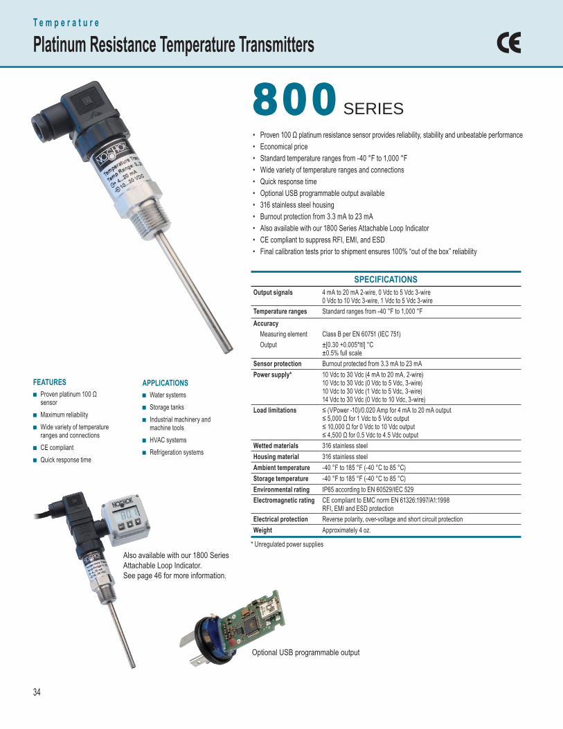
34
SPECIFICATIONS Output signals 4 mA to 20 mA 2-wire, 0 Vdc to 5 Vdc 3-wire
0 Vdc to 10 Vdc 3-wire, 1 Vdc to 5 Vdc 3-wireTemperature ranges Standard ranges from -40 °F to 1,000 °FAccuracy Measuring element Class B per EN 60751 (IEC 751) Output ±[0.30 +0.005*ltl] °C
±0.5% full scaleSensor protection Burnout protected from 3.3 mA to 23 mAPower supply* 10 Vdc to 30 Vdc (4 mA to 20 mA, 2-wire)
10 Vdc to 30 Vdc (0 Vdc to 5 Vdc, 3-wire)10 Vdc to 30 Vdc (1 Vdc to 5 Vdc, 3-wire)14 Vdc to 30 Vdc (0 Vdc to 10 Vdc, 3-wire)
Load limitations ≤ (VPower -10)/0.020 Amp for 4 mA to 20 mA output ≤ 5,000 Ω for 1 Vdc to 5 Vdc output ≤ 10,000 Ω for 0 Vdc to 10 Vdc output ≤ 4,500 Ω for 0.5 Vdc to 4.5 Vdc output
Wetted materials 316 stainless steelHousing material 316 stainless steelAmbient temperature -40 °F to 185 °F (-40 °C to 85 °C)Storage temperature -40 °F to 185 °F (-40 °C to 85 °C)Environmental rating IP65 according to EN 60529/IEC 529Electromagnetic rating CE compliant to EMC norm EN 61326:1997/A1:1998
RFI, EMI and ESD protectionElectrical protection Reverse polarity, over-voltage and short circuit protectionWeight Approximately 4 oz.
• Proven 100 Ω platinum resistance sensor provides reliability, stability and unbeatable performance• Economical price• Standard temperature ranges from -40 °F to 1,000 °F• Wide variety of temperature ranges and connections• Quick response time• Optional USB programmable output available• 316 stainless steel housing• Burnout protection from 3.3 mA to 23 mA• Also available with our 1800 Series Attachable Loop Indicator• CE compliant to suppress RFI, EMI, and ESD• Final calibration tests prior to shipment ensures 100% “out of the box” reliability
FEATURES ■ Proven platinum 100 Ω
sensor ■ Maximum reliability ■ Wide variety of temperature
ranges and connections ■ CE compliant ■ Quick response time
APPLICATIONS ■ Water systems ■ Storage tanks ■ Industrial machinery and
machine tools ■ HVAC systems ■ Refrigeration systems
T e m p e r a t u r e
Platinum Resistance Temperature Transmitters
800 800 SERIES
Also available with our 1800 Series Attachable Loop Indicator. See page 46 for more information.
Optional USB programmable output
* Unregulated power supplies

35
ORDERING INFORMATIONDIMENSIONS
WIRING DIAGRAMSELECTRICAL CONNECTIONS
Outline Dimensions
800 SERIES
2-WIRE WIRINGWiring Hirschmann Cable
+ Supply 1 Red+ Output 2 Black
3-WIRE WIRINGWiring Hirschmann Cable+ Supply 1 RedCommon 2 Black+ Output 3 White
Optional thermowells available in 316 SS, 304 SS and Brass.
Hirschmann with1/2″ NPT FemaleISO 4400 conduit
1.65"(42 mm)
1.06" sq.(27 mm)
Adjustable compression fi tting
* For temperature ranges above400 °F a 2.05″ (50 mm) extensionmust be added to this dimension
2.05″extension
Stemlength
Adjustablestem length
Hirschmann
Stem diameter(6 mm standard) 1.06"
(27 mm)
1.06" sq(27 mm)
1.10"(28 mm)
1.85"(47 mm)
2.16"(55 mm)
Stemlength
0.75"(19 mm)
1.06" HEX(27 mm)
1/2" NPT
800 – 50/300 – 1 – 1 – 8 – 8 – 040 – 6 EXAMPLE
Series ........................................................800Temperature range ...............50 °F to 300 °FAccuracy .................................... ±0.5% BFSLOutput signal .......................... 4 mA to 20 mAProcess connection ...............1/2″ NPT MaleElectrical connection .................HirschmannStem length ................................................. 4"Stem diameter ....................................... 6 mm
ORDERING INFORMATIONSERIES 800TEMPERATURE RANGES
-40/120 -40/120 °F 0/200 0/200 °F 0/300 0/300 °F 0/750 0/750 °F 25/125 25/125 °F 20/240 20/240 °F 50/300 50/300 °F 0/1000 0/1,000 °F
0/140 0/140 °F 0/250 0/250 °F 50/500 50/500 °FOther ranges available on special request
ACCURACY 1 Class B + (±0.5% BFSL)OUTPUT SIGNALS 1 4 mA to 20 mA, 2-wire 3 1 Vdc to 5 Vdc, 3-wire 34 4 mA to 20 mA, 2-wire, USB programmable
2 0 Vdc to 5 Vdc, 3-wire 5 0 Vdc to 10 Vdc, 3-wirePROCESS CONNECTIONS 2 1/4″ NPT Male 48 1/2″ NPT Male w/adjustable compression fitting
8 1/2″ NPT Male ELECTRICAL CONNECTIONS 1 36″ cable (connected to option 8) 14 Hirschmann connection w/ISO 4400 1/2″ NPT conduit
8 Hirschmann (DIN EN 175301-803 Form A) STEM LENGTHS 025 2.5″ 060 6″ 120 12″
040 4″ 090 9″STEM DIAMETERS 3 Tapered from 6 mm - 3 mm tip 6 6 mm 8 8 mm
Please consult your local NOSHOK Distributor or NOSHOK, Inc. for availability and delivery information.
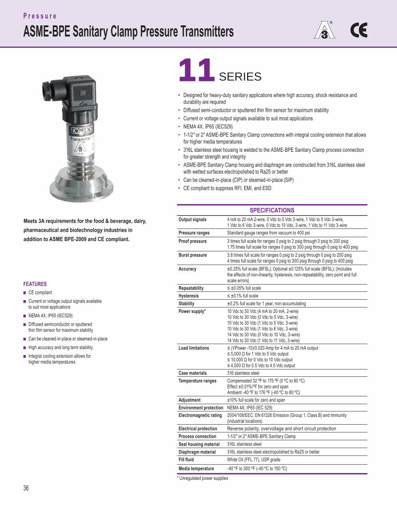
36
SPECIFICATIONS Output signals 4 mA to 20 mA 2-wire, 0 Vdc to 5 Vdc 3-wire, 1 Vdc to 5 Vdc 3-wire,
1 Vdc to 6 Vdc 3-wire, 0 Vdc to 10 Vdc, 3-wire, 1 Vdc to 11 Vdc 3-wirePressure ranges Standard gauge ranges from vacuum to 400 psiProof pressure 3 times full scale for ranges 0 psig to 2 psig through 0 psig to 200 psig
1.75 times full scale for ranges 0 psig to 300 psig through 0 psig to 400 psigBurst pressure 3.8 times full scale for ranges 0 psig to 2 psig through 0 psig to 200 psig
4 times full scale for ranges 0 psig to 300 psig through 0 psig to 400 psigAccuracy ±0.25% full scale (BFSL); Optional ±0.125% full scale (BFSL); (Includes
the effects of non-linearity, hysteresis, non-repeatability, zero point and fullscale errors)
Repeatability ≤ ±0.05% full scaleHysteresis ≤ ±0.1% full scaleStability ±0.2% full scale for 1 year, non-accumulatingPower supply* 10 Vdc to 30 Vdc (4 mA to 20 mA, 2-wire)
10 Vdc to 30 Vdc (0 Vdc to 5 Vdc, 3-wire)10 Vdc to 30 Vdc (1 Vdc to 5 Vdc, 3-wire)10 Vdc to 30 Vdc (1 Vdc to 6 Vdc, 3-wire)14 Vdc to 30 Vdc (0 Vdc to 10 Vdc, 3-wire)14 Vdc to 30 Vdc (1 Vdc to 11 Vdc, 3-wire)
Load limitations ≤ (VPower -10)/0.020 Amp for 4 mA to 20 mA output≤ 5,000 Ω for 1 Vdc to 5 Vdc output ≤ 10,000 Ω for 0 Vdc to 10 Vdc output ≤ 4,500 Ω for 0.5 Vdc to 4.5 Vdc output
Case materials 316 stainless steelTemperature ranges Compensated 32 ºF to 175 ºF (0 ºC to 80 ºC)
Effect ±0.01%/ºF for zero and span Ambient -40 ºF to 176 ºF (-40 ºC to 80 ºC)
Adjustment ±10% full scale for zero and span Environment protection NEMA 4X, IP65 (IEC 529)Electromagnetic rating 2004/108/EEC, EN 61326 Emission (Group 1, Class B) and Immunity
(industrial locations)Electrical protection Reverse polarity, overvoltage and short circuit protection Process connection 1-1/2" or 2" ASME-BPE Sanitary ClampSeal housing material 316L stainless steelDiaphragm material 316L stainless steel electropolished to Ra25 or betterFill fl uid White Oil (FFL 77), USP gradeMedia temperature -40 ºF to 300 ºF (-40 ºC to 150 ºC)
FEATURES ■ CE compliant ■ Current or voltage output signals available
to suit most applications ■ NEMA 4X, IP65 (IEC529) ■ Diffused semiconductor or sputtered
thin film sensor for maximum stability ■ Can be cleaned-in-place or steamed-in-place ■ High accuracy and long term stability ■ Integral cooling extension allows for
higher media temperatures
• Designed for heavy-duty sanitary applications where high accuracy, shock resistance and durability are required• Diffused semi-conductor or sputtered thin fi lm sensor for maximum stability• Current or voltage output signals available to suit most applications• NEMA 4X, IP65 (IEC529)• 1-1/2" or 2" ASME-BPE Sanitary Clamp connections with integral cooling extension that allows for higher media temperatures• 316L stainless steel housing is welded to the ASME-BPE Sanitary Clamp process connection for greater strength and integrity• ASME-BPE Sanitary Clamp housing and diaphragm are constructed from 316L stainless steel with wetted surfaces electropolished to Ra25 or better• Can be cleaned-in-place (CIP) or steamed-in-place (SIP)• CE compliant to suppress RFI, EMI, and ESD
11 11 SERIES
P r e s s u r e
ASME-BPE Sanitary Clamp Pressure Transmitters
Meets 3A requirements for the food & beverage, dairy, pharmaceutical and biotechnology industries in addition to ASME BPE-2009 and CE compliant.
* Unregulated power supplies
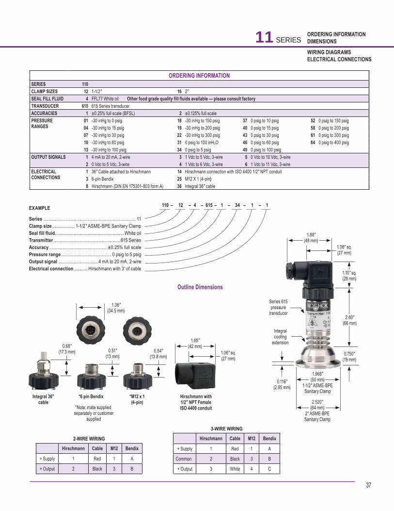
37
ORDERING INFORMATIONDIMENSIONS
WIRING DIAGRAMSELECTRICAL CONNECTIONS
Outline Dimensions
110 – 12 – 4 – 615 – 1 – 34 – 1 – 1 EXAMPLE
Series ............................................................................... 11Clamp size ................... 1-1/2″ ASME-BPE Sanitary ClampSeal fill fluid ...........................................................White oilTransmitter .........................................................615 SeriesAccuracy ..................................................±0.25% full scalePressure range ........................................... 0 psig to 5 psigOutput signal ..................................4 mA to 20 mA, 2-wireElectrical connection ........... Hirschmann with 3' of cable
11 SERIES
2-WIRE WIRING
Hirschmann Cable M12 Bendix
+ Supply 1 Red 1 A
+ Output 2 Black 3 B
3-WIRE WIRING
Hirschmann Cable M12 Bendix
+ Supply 1 Red 1 A
Common 2 Black 3 B
+ Output 3 White 4 C
1.36″(34.5 mm)
Integral 36″ cable
0.68"(17.3 mm)
*6 pin Bendix
0.51"(13 mm)
*M12 x 1(4-pin)
0.54"(13.8 mm)
Hirschmann with1/2″ NPT FemaleISO 4400 conduit
1.65"(42 mm)
1.06" sq.(27 mm)
*Note: mate supplied separately or customer
supplied
1.88"(48 mm)
1.06" sq.(27 mm)
1.10" sq.(28 mm)
2.60"(66 mm)
0.750"(19 mm)
0.116"(2.95 mm)
1.968"(50 mm)
1-1/2" ASME-BPE Sanitary Clamp
2.520"(64 mm)
2" ASME-BPE Sanitary Clamp
Series 615pressure
transducer
Integralcooling
extension
ORDERING INFORMATIONSERIES 110 CLAMP SIZES 12 1-1/2″ 16 2″ SEAL FILL FLUID 4 FFL77 White oil Other food grade quality fill fluids available — please consult factoryTRANSDUCER 615 615 Series transducerACCURACIES 1 ±0.25% full scale (BFSL) 2 ±0.125% full scalePRESSURERANGES
01 -30 inHg to 0 psig 16 -30 inHg to 150 psig 37 0 psig to 10 psig 52 0 psig to 150 psig04 -30 inHg to 15 psig 19 -30 inHg to 200 psig 40 0 psig to 15 psig 58 0 psig to 200 psig07 -30 inHg to 30 psig 22 -30 inHg to 300 psig 43 0 psig to 30 psig 61 0 psig to 300 psig10 -30 inHg to 60 psig 31 0 psig to 100 inH2O 46 0 psig to 60 psig 64 0 psig to 400 psig13 -30 inHg to 100 psig 34 0 psig to 5 psig 49 0 psig to 100 psig
OUTPUT SIGNALS 1 4 mA to 20 mA, 2-wire 3 1 Vdc to 5 Vdc, 3-wire 5 0 Vdc to 10 Vdc, 3-wire2 0 Vdc to 5 Vdc, 3-wire 4 1 Vdc to 6 Vdc, 3-wire 6 1 Vdc to 11 Vdc, 3-wire
ELECTRICALCONNECTIONS
1 36″ Cable attached to Hirschmann 14 Hirschmann connection with ISO 4400 1/2″ NPT conduit3 6-pin Bendix 25 M12 X 1 (4-pin)8 Hirschmann (DIN EN 175301-803 form A) 36 Integral 36″ cable

38
SPECIFICATIONS Output signals 4 mA to 20 mA 2-wire, 0 Vdc to 5 Vdc 3-wire, 1 Vdc to 5 Vdc 3-wire,
1 Vdc to 6 Vdc 3-wire, 0 Vdc to 10 Vdc, 3-wire, 1 Vdc to 11 Vdc 3-wirePressure ranges Standard gauge ranges from 1,000 psig to 15,000 psigProof pressure 1.75 times full scale for ranges 0 psig to 300 psig through 0 psig
to 10,000 psig 1.5 times full scale for ranges 0 psig to 15,000 psigBurst pressure 4 times full scale for ranges 0 psig to 300 psig through 0 psig to
10,000 psig 3 times full scale for ranges 0 psig to 15,000 psigAccuracy ±0.25% full scale (B.F.S.L.);
±0.125% full scale (optional)Repeatability ≤ ±0.05% full scaleHysteresis ≤ ±0.1% full scaleStability ≤ ±0.2% full scale for 1 year, non-accumulatingResponse time ≤ 1 ms (between 10% and 90% full scale)Power supply* 10 Vdc to 30 Vdc (4 mA to 20 mA, 2-wire)
10 Vdc to 30 Vdc (0 Vdc to 5 Vdc, 3-wire)10 Vdc to 30 Vdc (1 Vdc to 5 Vdc, 3-wire)10 Vdc to 30 Vdc (1 Vdc to 6 Vdc, 3-wire)14 Vdc to 30 Vdc (0 Vdc to 10 Vdc, 3-wire)14 Vdc to 30 Vdc (1 Vdc to 11 Vdc, 3-wire)
Load limitations ≤ (Vpower supply -10)/0.020 AmpWetted materials 316 stainless steel for vacuum through 300 psi; 17-4PH
stainless steel sensing diaphragm and 316 stainless steel processconnection for higher ranges
Housing material 316 stainless steelAdjustment ±10% full scale for zero and spanPressure cycle limit 150 HzDurability > 100,000,000 full scale cyclesTemperature ranges Compensated 32 °F to 176 °F (0 °C to 80 °C)
Effect ±0.017% full scale/ °F for zero and spanAmbient -40 °F to 185 °F (-40 °C to 85 °C)Media -4 °F to 302 °F (-20 °C to 150 °C)Storage -40 °F to 212 °F (-40 °C to 100 °C)
Environmental rating IP65, NEMA 4X according to EN 60529/IEC 529Electromagnetic rating 2004/108/EEC, EN 61326 Emission (Group 1, Class B) and Immunity
(industrial locations)Electrical protection Reverse polarity, over-voltage and short circuit protectionShock 1000 g’s per IEC 770Vibration 30 g’s per IEC 770Weight Approximately 3.5 oz.
• High accuracy, heavy-duty transmitter designed for high pressure sanitary homogenizer applications• Standard ranges from 1,000 psi to 15,000 psi• Span and zero adjustments• Sputtered thin fi lm sensor for maximum stability, shock resistance and durability• Current or voltage output signals available to suit most applications• NEMA 4X, IP65 (IEC529)• 316L stainless steel housing is welded to the 1-1/8" fl anged process connection for greater strength and integrity• 1-1/8" fl anged housing and diaphragm are constructed from 316L stainless steel with wetted surfaces electropolished to Ra25 or better• Can be cleaned-in-place (CIP) or steamed-in-place (SIP)• CE compliant to suppress RFI, EMI, and ESD
FEATURES ■ Current or voltage output signals available
to suit most applications ■ Span and zero adjustments ■ NEMA 4X, IP65 (IEC529) ■ Sputtered thin film sensor for maximum
stability and shock resistance ■ Ranges from 1,000 psig to 15,000 psig ■ High accuracy and long term stability ■ Can be cleaned-in-place or steamed-in-place
P r e s s u r e
Homogenizer Sanitary Pressure Transmitters
21 21 SERIES
Meets 3A requirements for the food & beverage, dairy, pharmaceutical and biotechnology industries in addition to ASME BPE-2009 and CE compliant.
* Unregulated power supplies
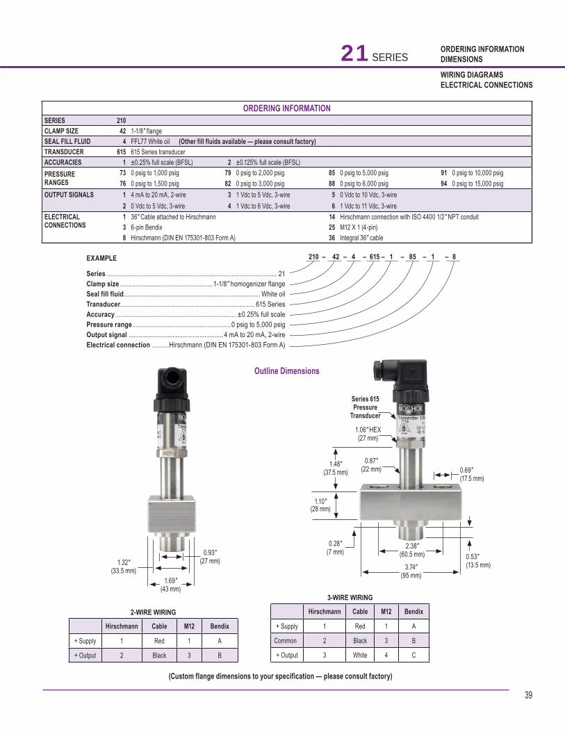
39
ORDERING INFORMATIONDIMENSIONS
WIRING DIAGRAMSELECTRICAL CONNECTIONS
Outline Dimensions
21 SERIES
2-WIRE WIRING
Hirschmann Cable M12 Bendix
+ Supply 1 Red 1 A
+ Output 2 Black 3 B
3-WIRE WIRING
Hirschmann Cable M12 Bendix
+ Supply 1 Red 1 A
Common 2 Black 3 B
+ Output 3 White 4 C
ORDERING INFORMATIONSERIES 210 CLAMP SIZE 42 1-1/8″ flange SEAL FILL FLUID 4 FFL77 White oil (Other fill fluids available — please consult factory)TRANSDUCER 615 615 Series transducerACCURACIES 1 ±0.25% full scale (BFSL) 2 ±0.125% full scale (BFSL) PRESSURERANGES
73 0 psig to 1,000 psig 79 0 psig to 2,000 psig 85 0 psig to 5,000 psig 91 0 psig to 10,000 psig76 0 psig to 1,500 psig 82 0 psig to 3,000 psig 88 0 psig to 6,000 psig 94 0 psig to 15,000 psig
OUTPUT SIGNALS 1 4 mA to 20 mA, 2-wire 3 1 Vdc to 5 Vdc, 3-wire 5 0 Vdc to 10 Vdc, 3-wire2 0 Vdc to 5 Vdc, 3-wire 4 1 Vdc to 6 Vdc, 3-wire 6 1 Vdc to 11 Vdc, 3-wire
ELECTRICALCONNECTIONS
1 36″ Cable attached to Hirschmann 14 Hirschmann connection with ISO 4400 1/2″ NPT conduit3 6-pin Bendix 25 M12 X 1 (4-pin)8 Hirschmann (DIN EN 175301-803 Form A) 36 Integral 36″ cable
210 – 42 – 4 – 615 – 1 – 85 – 1 – 8 EXAMPLE
Series ..................................................................................................... 21Clamp size .......................................................1-1/8″ homogenizer flangeSeal fill fluid ................................................................................. White oilTransducer ................................................................................ 615 SeriesAccuracy ........................................................................ ±0.25% full scalePressure range ...........................................................0 psig to 5,000 psigOutput signal ........................................................ 4 mA to 20 mA, 2-wireElectrical connection ..........Hirschmann (DIN EN 175301-803 Form A)
(Custom flange dimensions to your specification — please consult factory)
1.69"(43 mm)
0.93" (27 mm)1.32"
(33.5 mm) 3.74"(95 mm)
2.38"(60.5 mm)
1.48" (37.5 mm)
1.10"(28 mm)
0.28"(7 mm)
Series 615Pressure
Transducer
1.06" HEX(27 mm)
0.87"(22 mm)
0.53"(13.5 mm)
0.69"(17.5 mm)
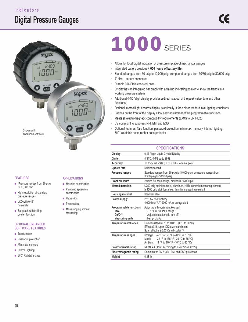
40
FEATURES ■ Pressure ranges from 30 psig
to 10,000 psig ■ High resolution of standard
pressure ranges ■ LCD with 0.43″
numerals ■ Bar graph with trailing
pointer function
OPTIONAL ENHANCED SOFTWARE FEATURES
■ Tare function ■ Password protection ■ Min./max. memory ■ Internal lighting ■ 300° Rotatable base
APPLICATIONS ■ Machine construction ■ Plant and apparatus
construction ■ Hydraulics ■ Pneumatics ■ Measuring equipment
monitoring
SPECIFICATIONS Display 0.43 ″ high Liquid Crystal DisplayDigits 4 STD. 4-1/2 up to 9999Accuracy ±0.25% full scale (BFSL); ±0.5 terminal pointUpdate rate 5 times/secondPressure ranges Standard ranges from 30 psig to 10,000 psig; compound ranges from
30/30 psig to 30/600 psigProof pressure 2 times full scale range, maximum 15,000 psiWetted materials ≤750 psig stainless steel, aluminum, NBR, ceramic measuring element
≥ 1000 psig stainless steel, thin-fi lm measuring elementHousing material Stainless steelPower supply 2 x 1.5V “AA” battery
4,000 hrs (“AA” 2000 mAh), unregulatedProgrammable functions Tare On/Off Measuring units
Adjustable through front key pad ± 20% of full scale range Adjustable automatic turn off bar, psi, MPa
Temperature infl uence Compensated 32 °F to 140 °F (0 °C to 60 °C)Effect ±0.15% per 10K at zero and spanSpan effect is ±0.005% full scale/ °F
Temperature ranges StorageMediaAmbient
-4 °F to 158 °F (-20 °C to 70 °C)-22 °F to 185 °F (-30 °C to 85 °C)14 °F to 140 °F (-10 °C to 60 °C)
Environmental rating NEMA 4X (IP 65 according to EN60529/IEC529)Electromagnetic rating Compliant to EN 61326, EMI and ESD protectionWeight 0.88 lb.
• Allows for local digital indication of pressure in place of mechanical gauges• Integrated battery provides 4,000 hours of battery life• Standard ranges from 30 psig to 10,000 psig; compound ranges from 30/30 psig to 30/600 psig• 4" size – bottom connected• Durable 304 Stainless steel case• Display has an integrated bar graph with a trailing indicating pointer to show the trends in a working pressure system• Additional 4-1/2" digit display provides a direct readout of the peak value, tare and other functions• Optional internal light ensures display is optimally lit for a clear readout in all lighting conditions• Buttons on the front of the display allow easy adjustment of the programmable functions• Meets all electromagnetic compatibility requirements (EMC) to EN 61326• CE compliant to suppress RFI, EMI and ESD• Optional features: Tare function, password protection, min./max. memory, internal lighting, 300° rotatable base, rubber case protector
1000 1000 SERIES
I n d i c a t o r s
Digital Pressure Gauges
Shown withenhanced software.
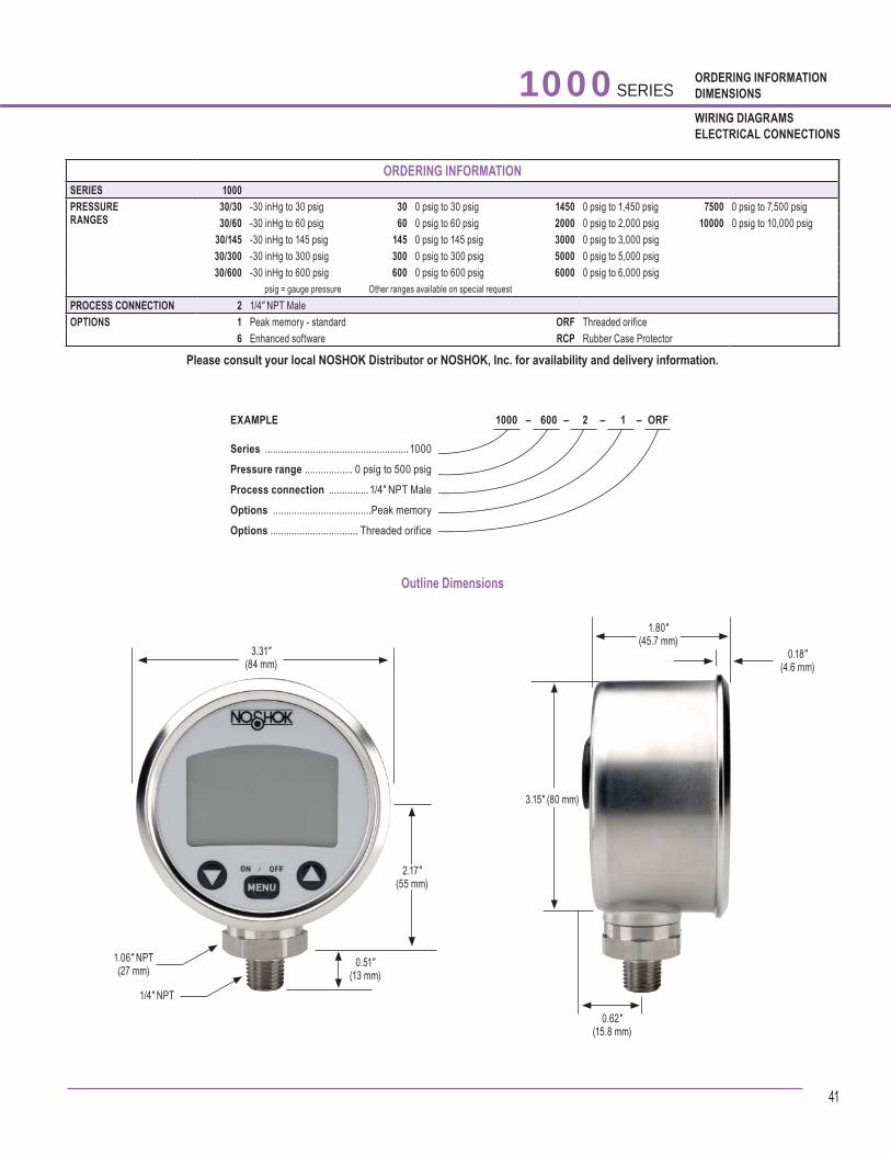
41
ORDERING INFORMATIONDIMENSIONS
WIRING DIAGRAMSELECTRICAL CONNECTIONS
Outline Dimensions
1000 SERIES
1000 – 600 – 2 – 1 – ORF EXAMPLE
Series ......................................................1000
Pressure range .................. 0 psig to 500 psig
Process connection ...............1/4″ NPT Male
Options .....................................Peak memory
Options ................................. Threaded orifice
ORDERING INFORMATIONSERIES 1000 PRESSURE RANGES
30/30 -30 inHg to 30 psig 30 0 psig to 30 psig 1450 0 psig to 1,450 psig 7500 0 psig to 7,500 psig 30/60 -30 inHg to 60 psig 60 0 psig to 60 psig 2000 0 psig to 2,000 psig 10000 0 psig to 10,000 psig
30/145 -30 inHg to 145 psig 145 0 psig to 145 psig 3000 0 psig to 3,000 psig 30/300 -30 inHg to 300 psig 300 0 psig to 300 psig 5000 0 psig to 5,000 psig30/600 -30 inHg to 600 psig 600 0 psig to 600 psig 6000 0 psig to 6,000 psig
psig = gauge pressure Other ranges available on special requestPROCESS CONNECTION 2 1/4″ NPT MaleOPTIONS 1 Peak memory - standard ORF Threaded orifice
6 Enhanced software RCP Rubber Case Protector
Please consult your local NOSHOK Distributor or NOSHOK, Inc. for availability and delivery information.
1.06" NPT(27 mm)
1/4" NPT
0.51"(13 mm)
3.31"(84 mm)
2.17"(55 mm)
3.15" (80 mm)
0.62"(15.8 mm)
1.80"(45.7 mm)
0.18"(4.6 mm)

42
SPECIFICATIONS Pressure ranges 15 psig to 30 psig through 15 psig to 150 psigMeasuring element NBR diaphragm, optional FKM or EPDMProcess connection 1/8″ NPT MaleConnection material Brass, optional stainless steelCase Brass, optional stainless steelSwitching function 1 SPST N.O. or N.C. contactAdjustment Adjustment screw from 5 psig to 150 psig dependent on full scale rangeHysteresis < 10% of the adjusted valueRepeatability 5% of the adjusted valueContact rating up to 42 Vdc -2AContact material Silver plated, optional gold platedTemperature ranges Storage -13 °F to 185 °F (-25 °C to 85 °C)
Media -13 °F to 185 °F (-25 °C to 85 °C)Ambient -13 °F to 185 °F (-25 °C to 85 °C)
Electrical connection 6.3 mm spade terminalsEnvironmental protection Housing NEMA 4:IP65Weight Approximately 0.07 lb
APPLICATIONS ■ Hydraulic systems ■ Industrial machinery
or machine tools ■ Pumps and
compressors
FEATURES ■ One piece machined housing ■ Compact size ■ External adjustment screw
• Rugged one-piece machined housing provides maximum durability• Compact size allows installation where space is limited• Ranges available from 5 psi to 150 psi in either normally open or normally closed contacts• External adjustment screw for ease of setting the switching point on-site• Utilizes a proven diaphragm type sensing element to provide excellent accuracy• Special versions are available with alternate diaphragm, housing and contact materials to meet most requirements• Cost-effective
100 100 SERIES
P r e s s u r e
Mechanical Miniature Low-Pressure Switch
N.C.
N.O.

43
ORDERING INFORMATIONDIMENSIONS
WIRING DIAGRAMSELECTRICAL CONNECTIONS
100 SERIES
ORDERING INFORMATIONSERIES 100 SWITCH FUNCTIONS 1 1 Normally open 2 1 Normally closed PROCESS CONNECTION 1 1/8″ NPT Male ADJUSTABLE RANGES 5/30 5 psig to 30 psig 15/150 15 psig to 150 psigELECTRICAL CONNECTION 4 6.3 mm spade terminalsSWITCH POINT (if required) Specify pressure
Please consult your local NOSHOK Distributor or NOSHOK, Inc. for availability and delivery information.
100 – 2 – 1 – 15/150 – 4 – 100 EXAMPLE
Series ..............................................................100Switch function ....................... 1 normally closedProcess connection .................... 1/8″ NPT MaleAdjustable range .................. 15 psig to 150 psigElectrical connection ...6.3 mm spade terminalsSwitch point ............................................100 psig
Outline Dimensions
Switch Wiring and Schematics
Normally Closed Normally Open
0.91"(23 mm)
0.38"(9.8 mm)
0.91"(23 mm)
0.75" HEX(19 mm)
1/8" NPT0.35"
(9 mm)
P P
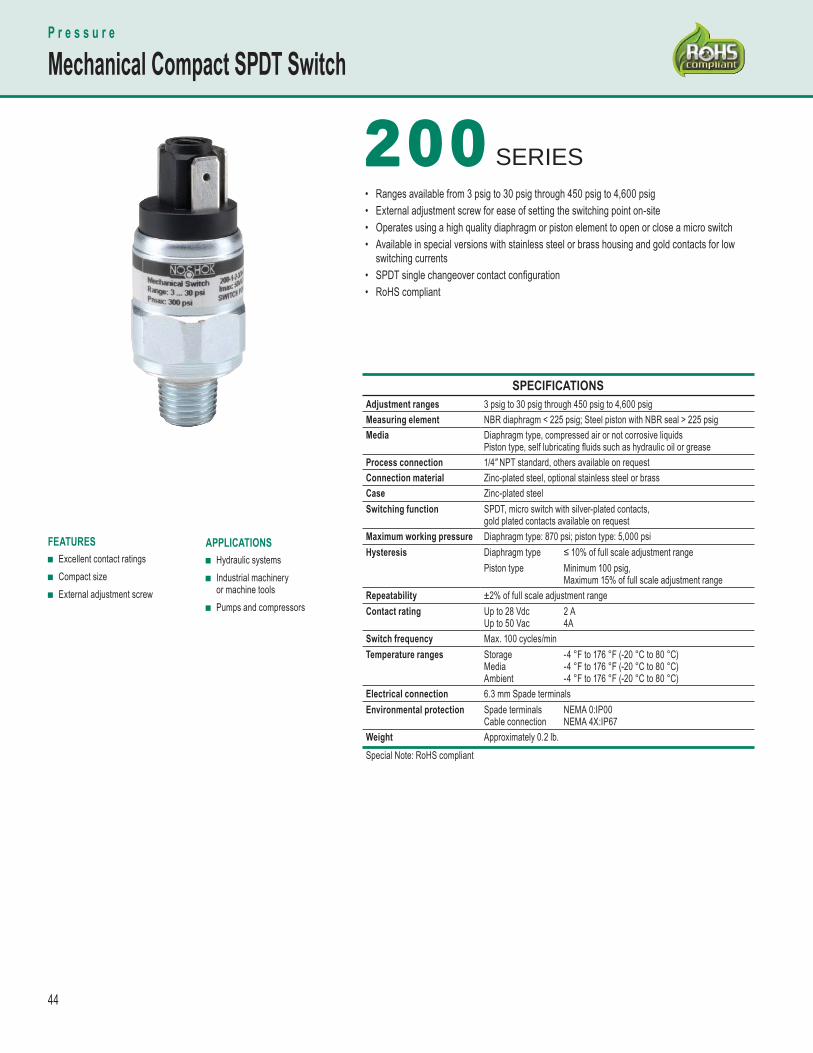
44
APPLICATIONS ■ Hydraulic systems ■ Industrial machinery
or machine tools ■ Pumps and compressors
SPECIFICATIONS Adjustment ranges 3 psig to 30 psig through 450 psig to 4,600 psig Measuring element NBR diaphragm < 225 psig; Steel piston with NBR seal > 225 psig Media Diaphragm type, compressed air or not corrosive liquids
Piston type, self lubricating fl uids such as hydraulic oil or grease Process connection 1/4″ NPT standard, others available on requestConnection material Zinc-plated steel, optional stainless steel or brassCase Zinc-plated steelSwitching function SPDT, micro switch with silver-plated contacts,
gold plated contacts available on request Maximum working pressure Diaphragm type: 870 psi; piston type: 5,000 psiHysteresis Diaphragm type ≤ 10% of full scale adjustment range
Piston type Minimum 100 psig, Maximum 15% of full scale adjustment range
Repeatability ±2% of full scale adjustment rangeContact rating Up to 28 Vdc
Up to 50 Vac2 A4A
Switch frequency Max. 100 cycles/min Temperature ranges Storage
MediaAmbient
-4 °F to 176 °F (-20 °C to 80 °C) -4 °F to 176 °F (-20 °C to 80 °C)-4 °F to 176 °F (-20 °C to 80 °C)
Electrical connection 6.3 mm Spade terminalsEnvironmental protection Spade terminals
Cable connectionNEMA 0:IP00 NEMA 4X:IP67
Weight Approximately 0.2 lb. Special Note: RoHS compliant
FEATURES ■ Excellent contact ratings ■ Compact size ■ External adjustment screw
• Ranges available from 3 psig to 30 psig through 450 psig to 4,600 psig• External adjustment screw for ease of setting the switching point on-site• Operates using a high quality diaphragm or piston element to open or close a micro switch• Available in special versions with stainless steel or brass housing and gold contacts for low switching currents• SPDT single changeover contact confi guration• RoHS compliant
P r e s s u r e
Mechanical Compact SPDT Switch
200 200 SERIES
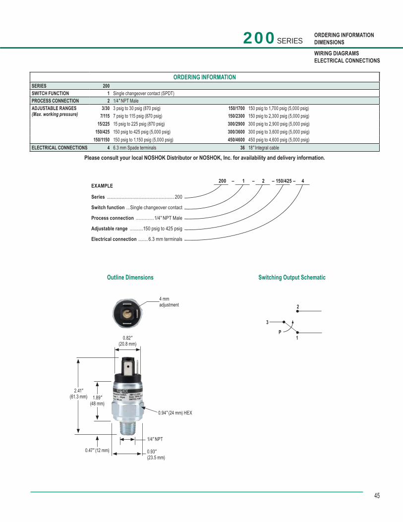
45
ORDERING INFORMATIONDIMENSIONS
WIRING DIAGRAMSELECTRICAL CONNECTIONS
200 SERIES
Outline Dimensions
ORDERING INFORMATIONSERIES 200 SWITCH FUNCTION 1 Single changeover contact (SPDT)PROCESS CONNECTION 2 1/4″ NPT Male ADJUSTABLE RANGES(Max. working pressure)
3/30 3 psig to 30 psig (870 psig) 150/1700 150 psig to 1,700 psig (5,000 psig)7/115 7 psig to 115 psig (870 psig) 150/2300 150 psig to 2,300 psig (5,000 psig)
15/225 15 psig to 225 psig (870 psig) 300/2900 300 psig to 2,900 psig (5,000 psig)150/425 150 psig to 425 psig (5,000 psig) 300/3600 300 psig to 3,600 psig (5,000 psig)
150/1150 150 psig to 1,150 psig (5,000 psig) 450/4600 450 psig to 4,600 psig (5,000 psig)ELECTRICAL CONNECTIONS 4 6.3 mm Spade terminals 36 18″ Integral cable
Please consult your local NOSHOK Distributor or NOSHOK, Inc. for availability and delivery information.
200 – 1 – 2 – 150/425 – 4 EXAMPLE
Series ........................................................ 200
Switch function ...Single changeover contact
Process connection ...............1/4″ NPT Male
Adjustable range ...........150 psig to 425 psig
Electrical connection ........ 6.3 mm terminals
4 mmadjustment
0.82"(20.8 mm)
2.41"(61.3 mm) 1.89"
(48 mm)
0.93"(23.5 mm)
1/4" NPT
0.47" (12 mm)
0.94" (24 mm) HEX
Switching Output Schematic
P
3
2
1
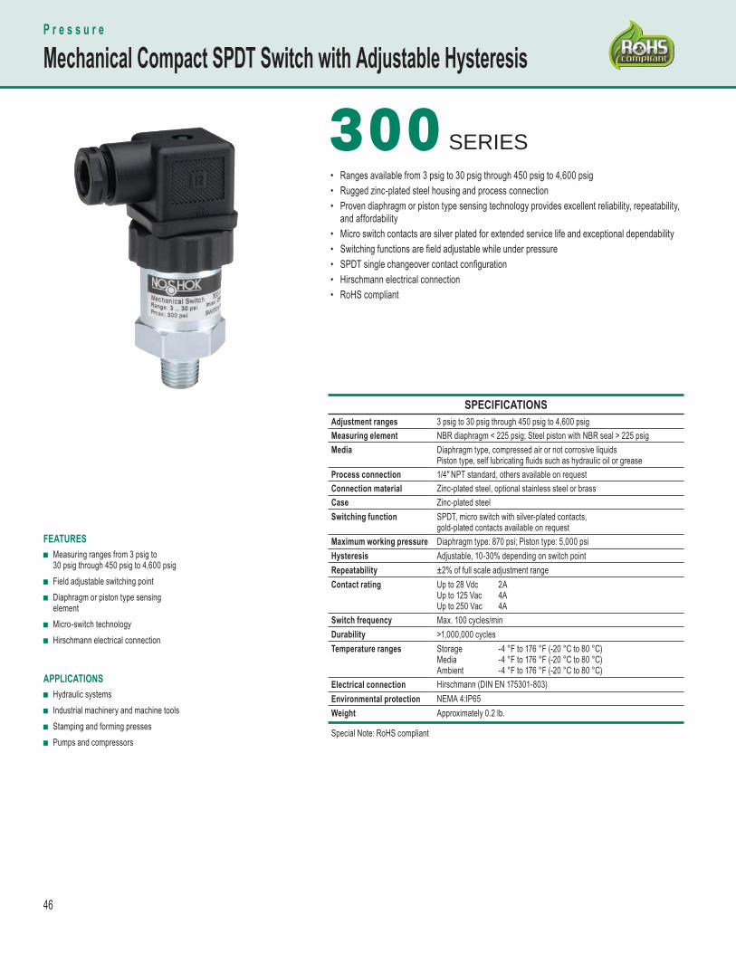
46
SPECIFICATIONS Adjustment ranges 3 psig to 30 psig through 450 psig to 4,600 psig Measuring element NBR diaphragm < 225 psig; Steel piston with NBR seal > 225 psig Media Diaphragm type, compressed air or not corrosive liquids
Piston type, self lubricating fl uids such as hydraulic oil or grease Process connection 1/4″ NPT standard, others available on requestConnection material Zinc-plated steel, optional stainless steel or brassCase Zinc-plated steelSwitching function SPDT, micro switch with silver-plated contacts,
gold-plated contacts available on request Maximum working pressure Diaphragm type: 870 psi; Piston type: 5,000 psiHysteresis Adjustable, 10-30% depending on switch pointRepeatability ±2% of full scale adjustment rangeContact rating Up to 28 Vdc
Up to 125 VacUp to 250 Vac
2A4A4A
Switch frequency Max. 100 cycles/minDurability >1,000,000 cycles Temperature ranges Storage
MediaAmbient
-4 °F to 176 °F (-20 °C to 80 °C) -4 °F to 176 °F (-20 °C to 80 °C) -4 °F to 176 °F (-20 °C to 80 °C)
Electrical connection Hirschmann (DIN EN 175301-803)Environmental protection NEMA 4:IP65Weight Approximately 0.2 lb.
Special Note: RoHS compliant
FEATURES ■ Measuring ranges from 3 psig to
30 psig through 450 psig to 4,600 psig ■ Field adjustable switching point ■ Diaphragm or piston type sensing
element ■ Micro-switch technology ■ Hirschmann electrical connection
APPLICATIONS ■ Hydraulic systems ■ Industrial machinery and machine tools ■ Stamping and forming presses ■ Pumps and compressors
• Ranges available from 3 psig to 30 psig through 450 psig to 4,600 psig• Rugged zinc-plated steel housing and process connection• Proven diaphragm or piston type sensing technology provides excellent reliability, repeatability, and affordability• Micro switch contacts are silver plated for extended service life and exceptional dependability• Switching functions are fi eld adjustable while under pressure• SPDT single changeover contact confi guration• Hirschmann electrical connection• RoHS compliant
300 300 SERIES
P r e s s u r e
Mechanical Compact SPDT Switch with Adjustable Hysteresis

47
ORDERING INFORMATIONDIMENSIONS
WIRING DIAGRAMSELECTRICAL CONNECTIONS
Outline Dimensions
ORDERING INFORMATIONSERIES 300 SWITCH FUNCTION 1 Single changeover contact, SPDT PROCESS CONNECTION 2 1/4″ NPT Male ADJUSTABLE RANGES(Max. working pressure)
3/30 3 psig to 30 psig (870 psig) 150/1700 150 psig to 1,700 psig (5,000 psig)7/115 7 psig to 115 psig (870 psig) 150/2300 150 psig to 2,300 psig (5,000 psig)
15/225 15 psig to 225 psig (870 psig) 300/2900 300 psig to 2,900 psig (5,000 psig)150/425 150 psig to 425 psig (5,000 psig) 300/3600 300 psig to 3,600 psig (5,000 psig)
150/1150 150 psig to 1,150 psig (5,000 psig) 450/4600 450 psig to 4,600 psig (5,000 psig)ELECTRICAL CONNECTIONS 1 36″ Cable (connected to option 8) 8 Hirschmann (DIN EN 175301-803 form A)
Please consult your local NOSHOK Distributor or NOSHOK, Inc. for availability and delivery information.
300 SERIES
300 – 1 – 2 – 15/225 – 8 EXAMPLE
Series ........................................................300
Switch function ...Single changeover contact
Process connection ...............1/4″ NPT Male
Adjustable range .............15 psig to 225 psig
Electrical connection .................Hirschmann
Additional Ordering InformationSwitch Set Point(s) (please specify)
1 / BLK
2 / WHT
P
3 / RED
1 2
3
psi psi
Switch Function
HysteresisFunction
Switching Output Schematic
1.06" sq.(27 mm)
1.10"(28 mm)
1.77"(45 mm)
0.47"(12 mm)
1/4" NPT
1.06" HEX(27 mm)
1.06"(27 mm)
1.85"(47 mm)
1.35"(34 mm)

48
SPECIFICATIONS Maximum working pressure
0 psig to 300 psig through 0 psig to 5,000 psig
Measuring element NBR diaphragm ≤ 230 psig Stainless Steel piston with NBR seal ≥ 500 psig
Media Diaphragm type, compressed air or non-corrosive liquids Piston type, self-lubricating fl uids such as hydraulic oil or grease
Process connection 1/4″ NPT and 7/16-20 SAE standard, others available on requestConnection material Zinc-plated steel, stainless steel optional Case Zinc-plated steelSwitching function SPDT, micro switch with silver-plated self cleaning contactsAdjustment Adjustment knob from 3 psig to 4,600 psig dependent on
full scale range Hysteresis Diaphragm type, 1% to 11% of adjustment range full scale
Piston type, 2% to 8% of adjustment range full scale Repeatability ±2% of full scaleFrequency Max. 200 cycles/min.Contact rating Up to 28 Vdc - max 4A
Up to 250 Vac - max 3A Temperature range Storage
MediaAmbient
13 °F to 185 °F (-25 °C to 85 °C)1 4 °F to 176 °F (-10 °C to 80 °C) 14 °F to 176 °F (-10 °C to 80 °C)
Electrical connection Hirschmann (DIN EN 175301-803 Form A), M12 x 1 (4-pin available upon request)
Shock 30 g’s per IEC 770Vibration 10 g’s per IEC 770Environmental protection NEMA 4: IP65 for Hirschmann
NEMA 4X: IP67 for M12 x 1 CE certifi cation Acc. to EU Standard 73/23/EWGWeight Approximately 0.66 lb.
FEATURES ■ Excellent repeatability ±2% of full scale ■ Robust design with zinc die-cast housing ■ 360º rotatable male connections
ranges ≥ 150/425 psi ■ Easy to adjust ■ High loadability (shock 30g, vibration 10g) ■ IP65 Hirschmann connector
IP67 M12x1 (4-pin) ■ Flange connection (optional) ■ LED status indicator (optional)
APPLICATIONS ■ Hydraulic systems, including
mobile hydraulics ■ Pneumatic systems ■ Power generation ■ Pumps & compressors ■ Marine
400400 SERIES• Stable switching point setting• Converts pneumatic and hydraulic pressure into switching functions• Excellent repeatability of ±2% of full scale, designed for applications requiring maximum accuracy under high loads• Robust design with zinc die-cast housing• 360° rotatable male connections• High loadability (shock 30 g, vibration 10 g)• SPDT, can be normally open (N.O.) or normally closed (N.C.) depending on the wiring• The switching point is fully adjustable by means of a simple adjustment knob within the adjustment range• Includes a locking mechanism for switch point adjustment• Hirschmann (DIN EN 175301-803 Form A) with optional 36" cable, or M12 x 1 (4-pin) electrical connection• Flange connection (optional)• LED status indicator (optional)
P r e s s u r e
Mechanical Heavy-Duty Switch

49
ORDERING INFORMATIONDIMENSIONS
WIRING DIAGRAMSELECTRICAL CONNECTIONS
400 SERIES
ORDERING INFORMATIONSERIES 400 SWITCH FUNCTION 1 Single Pole Double Throw (SPDT)PROCESS CONNECTIONS* 2 1/4″ NPT Male 19 G 1/4 B Female
5 1/4″ NPT Female 45 SAE J1926-3:7/16-2010 G 1/4 B Male
SWITCH ADJUSTMENTRANGES (MAXIMUMWORKING PRESSURE)
3/30 3 psig to 30 psig (300 psig) 150/1700 150 psig to 1,700 psig (5,000 psig)7/115 7 psig to 115 psig (300 psig) 150/2300 150 psig to 2,300 psig (5,000 psig)
15/225 15 psig to 225 psig (300 psig) 300/2900 300 psig to 2,900 psig (5,000 psig) 150/425 150 psig to 425 psig (5,000 psig) 300/3600 300 psig to 3,600 psig (5,000 psig)
150/1150 150 psig to 1,150 psig (5,000 psig) 450/4600 450 psig to 4,600 psig (5,000 psig)ELECTRICAL CONNECTIONS 1 36″ Cable (connected to option 8) 8 DIN EN 175301-803 Form A
2 M12 x 1 (4-pin) 46 Hirschmann with LED status indicator * Note: Stainless steel connection available, consult factory
Please consult your local NOSHOK Distributor or NOSHOK, Inc. for availability and delivery information.
400 – 1 – 2 – 3/30 – 8 EXAMPLE
Series ........................................................400
Switch function ....Single Pole Double Throw
Process connection ...............1/4″ NPT Male
Adjustable range .................3 psig to 30 psig
Electrical connection .................Hirschmann
Outline Dimensions Switching Output Schematic
1.57"(40 mm)
HirschmannDIN EN 175301-803
Form A
3.66"(93 mm)
1.18"(30 mm)
1.18"(30 mm)
HirschmannDIN 43650
M12 x 1(4-pin)
1 2
3
1
4
2
3
HirschmannDIN 43650
M12 x 1 (4-pin)
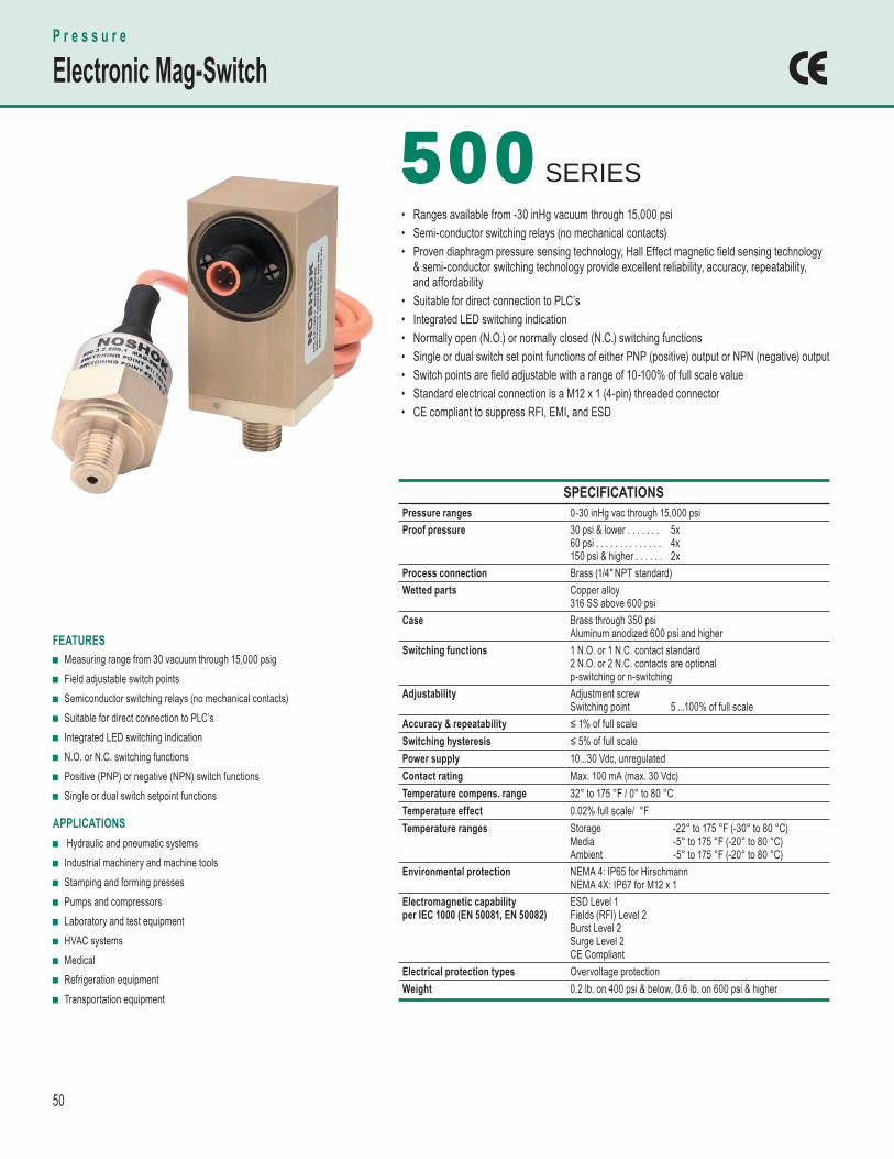
50
SPECIFICATIONS Pressure ranges 0-30 inHg vac through 15,000 psi Proof pressure 30 psi & lower . . . . . . .
60 psi . . . . . . . . . . . . . .150 psi & higher . . . . . .
5x4x2x
Process connection Brass (1/4″ NPT standard)Wetted parts Copper alloy
316 SS above 600 psi Case Brass through 350 psi
Aluminum anodized 600 psi and higher Switching functions 1 N.O. or 1 N.C. contact standard
2 N.O. or 2 N.C. contacts are optional p-switching or n-switching
Adjustability Adjustment screwSwitching point 5 ...100% of full scale
Accuracy & repeatability ≤ 1% of full scale Switching hysteresis ≤ 5% of full scalePower supply 10...30 Vdc, unregulatedContact rating Max. 100 mA (max. 30 Vdc)Temperature compens. range 32° to 175 °F / 0° to 80 °C Temperature effect 0.02% full scale/ °F Temperature ranges Storage
MediaAmbient
-22° to 175 °F (-30° to 80 °C) -5° to 175 °F (-20° to 80 °C) -5° to 175 °F (-20° to 80 °C)
Environmental protection NEMA 4: IP65 for Hirschmann NEMA 4X: IP67 for M12 x 1
Electromagnetic capability per IEC 1000 (EN 50081, EN 50082)
ESD Level 1 Fields (RFI) Level 2 Burst Level 2 Surge Level 2 CE Compliant
Electrical protection types Overvoltage protectionWeight 0.2 lb. on 400 psi & below, 0.6 lb. on 600 psi & higher
FEATURES ■ Measuring range from 30 vacuum through 15,000 psig ■ Field adjustable switch points ■ Semiconductor switching relays (no mechanical contacts) ■ Suitable for direct connection to PLC’s ■ Integrated LED switching indication ■ N.O. or N.C. switching functions ■ Positive (PNP) or negative (NPN) switch functions ■ Single or dual switch setpoint functions
APPLICATIONS ■ Hydraulic and pneumatic systems ■ Industrial machinery and machine tools ■ Stamping and forming presses ■ Pumps and compressors ■ Laboratory and test equipment ■ HVAC systems ■ Medical ■ Refrigeration equipment ■ Transportation equipment
500500 SERIES• Ranges available from -30 inHg vacuum through 15,000 psi• Semi-conductor switching relays (no mechanical contacts)• Proven diaphragm pressure sensing technology, Hall Effect magnetic fi eld sensing technology & semi-conductor switching technology provide excellent reliability, accuracy, repeatability, and affordability• Suitable for direct connection to PLC’s• Integrated LED switching indication• Normally open (N.O.) or normally closed (N.C.) switching functions• Single or dual switch set point functions of either PNP (positive) output or NPN (negative) output• Switch points are fi eld adjustable with a range of 10-100% of full scale value• Standard electrical connection is a M12 x 1 (4-pin) threaded connector• CE compliant to suppress RFI, EMI, and ESD
P r e s s u r e
Electronic Mag-Switch
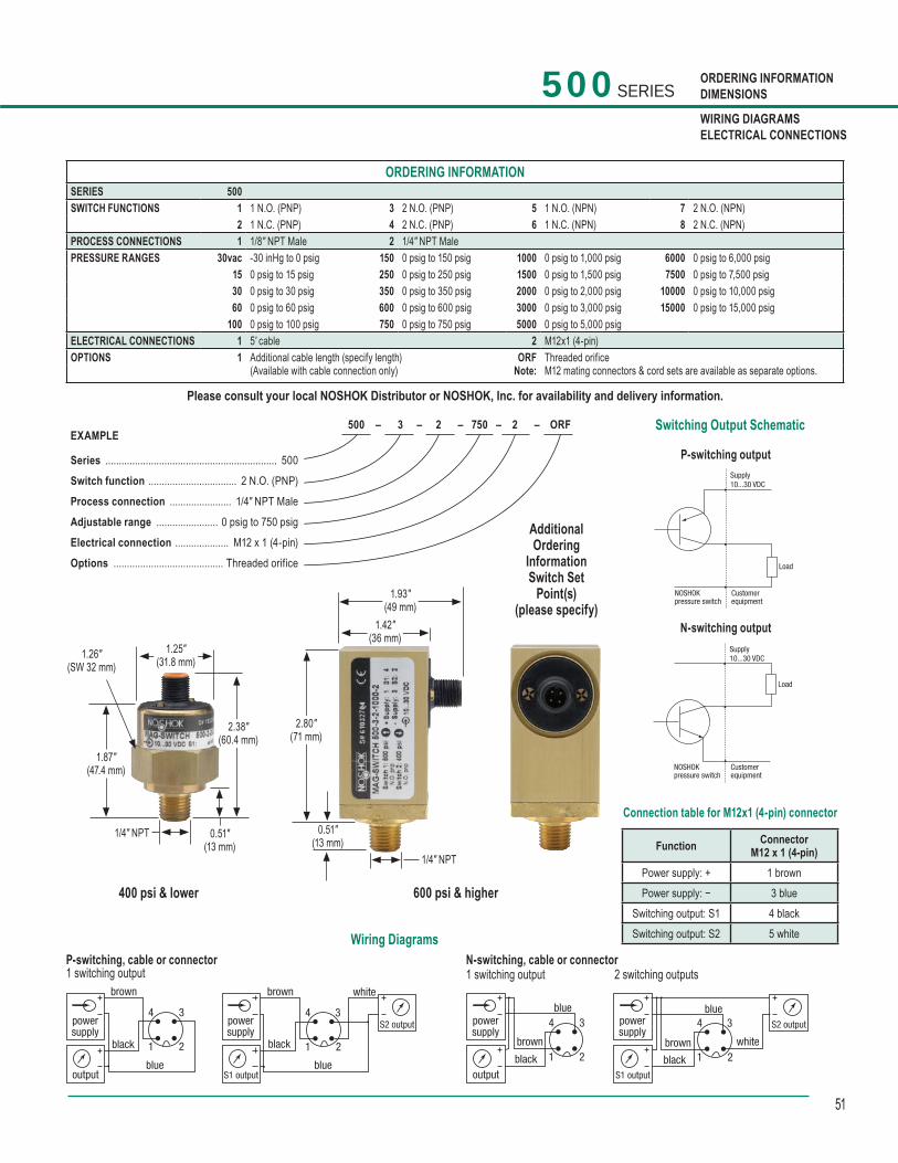
51
ORDERING INFORMATIONDIMENSIONS
WIRING DIAGRAMSELECTRICAL CONNECTIONS
500 SERIES
ORDERING INFORMATIONSERIES 500 SWITCH FUNCTIONS 1 1 N.O. (PNP) 3 2 N.O. (PNP) 5 1 N.O. (NPN) 7 2 N.O. (NPN)
2 1 N.C. (PNP) 4 2 N.C. (PNP) 6 1 N.C. (NPN) 8 2 N.C. (NPN)PROCESS CONNECTIONS 1 1/8″ NPT Male 2 1/4″ NPT Male PRESSURE RANGES 30vac -30 inHg to 0 psig 150 0 psig to 150 psig 1000 0 psig to 1,000 psig 6000 0 psig to 6,000 psig
15 0 psig to 15 psig 250 0 psig to 250 psig 1500 0 psig to 1,500 psig 7500 0 psig to 7,500 psig30 0 psig to 30 psig 350 0 psig to 350 psig 2000 0 psig to 2,000 psig 10000 0 psig to 10,000 psig60 0 psig to 60 psig 600 0 psig to 600 psig 3000 0 psig to 3,000 psig 15000 0 psig to 15,000 psig
100 0 psig to 100 psig 750 0 psig to 750 psig 5000 0 psig to 5,000 psigELECTRICAL CONNECTIONS 1 5' cable 2 M12x1 (4-pin) OPTIONS 1 Additional cable length (specify length)
(Available with cable connection only)ORF
Note: Threaded orifice M12 mating connectors & cord sets are available as separate options.
Please consult your local NOSHOK Distributor or NOSHOK, Inc. for availability and delivery information.
500 – 3 – 2 – 750 – 2 – ORF EXAMPLE
Series ................................................................ 500
Switch function ................................. 2 N.O. (PNP)
Process connection ....................... 1/4″ NPT Male
Adjustable range ....................... 0 psig to 750 psig
Electrical connection .................... M12 x 1 (4-pin)
Options ......................................... Threaded orifice
Switching Output Schematic
P-switching output
N-switching output
Connection table for M12x1 (4-pin) connector
600 psi & higher
Wiring DiagramsN-switching, cable or connector1 switching output 2 switching outputs
P-switching, cable or connector1 switching output
400 psi & lower
AdditionalOrdering
InformationSwitch Set
Point(s)(please specify)
1.87"(47.4 mm)
1.25"(31.8 mm)1.26"
(SW 32 mm)
0.51"(13 mm)
2.38"(60.4 mm)
1/4" NPT
1.93"(49 mm)
1.42"(36 mm)
2.80"(71 mm)
0.51"(13 mm)
1/4" NPTFunction Connector
M12 x 1 (4-pin)Power supply: + 1 brownPower supply: − 3 blue
Switching output: S1 4 blackSwitching output: S2 5 white
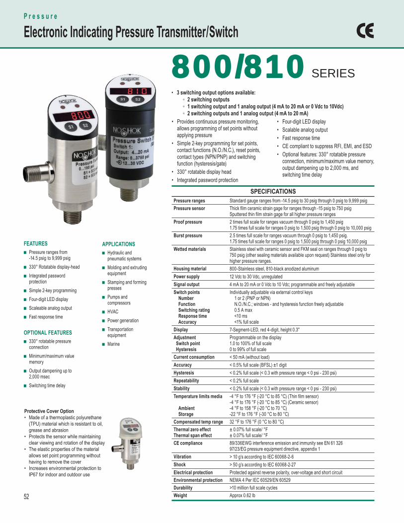
52
SPECIFICATIONS Pressure ranges Standard gauge ranges from -14.5 psig to 30 psig through 0 psig to 9,999 psig Pressure sensor Thick fi lm ceramic strain gage for ranges through -15 psig to 750 psig
Sputtered thin fi lm strain gage for all higher pressure ranges Proof pressure 2 times full scale for ranges vacuum through 0 psig to 1,450 psig
1.75 times full scale for ranges 0 psig to 1,500 psig through 0 psig to 10,000 psig Burst pressure 2.5 times full scale for ranges vacuum through 0 psig to 1,450 psig.
1.75 times full scale for ranges 0 psig to 1,500 psig through 0 psig 10,000 psig Wetted materials Stainless steel with ceramic sensor and FKM seal on ranges through 0 psig to
750 psig (other sealing materials available upon request) Stainless steel only for higher pressure ranges.
Housing material 800-Stainless steel, 810-black anodized aluminumPower supply 12 Vdc to 30 Vdc, unregulatedSignal output 4 mA to 20 mA or 0 Vdc to 10 Vdc; programmable and freely adjustableSwitch points Number Function Switching rating Response time Accuracy
Individually adjustable via external control keys 1 or 2 (PNP or NPN) N.O./N.C.; windows - and hysteresis function freely adjustable 0.5 A max <10 ms <1% full scale
Display 7-Segment-LED, red 4-digit, height 0.3"Adjustment Switch point Hysteresis
Programmable on the display1.0 to 100% of full scale0 to 99% of full scale
Current consumption < 50 mA (without load)Accuracy < 0.5% full scale (BFSL) ±1 digitHysteresis < 0.2% full scale (< 0.3 with pressure range < 0 psi - 230 psi)Repeatability < 0.2% full scale Stability < 0.2% full scale (< 0.3 with pressure range < 0 psi - 230 psi)Temperature limits media
Ambient Storage
-4 °F to 176 °F (-20 °C to 85 °C) (Thin fi lm sensor) -4 °F to 176 °F (-20 °C to 85 °C) (Ceramic sensor)-4 °F to 158 °F (-20 °C to 70 °C) -22 °F to 176 °F (-30 °C to 80 °C)
Compensated temp range 32 °F to 176 °F (0 °C to 80 °C) Thermal zero effect Thermal span effect
± 0.07% full scale/ °F± 0.07% full scale/ °F
CE compliance 89/336EWG interference emission and immunity see EN 61 326 97/23/EG pressure equipment directive, appendix 1
Vibration > 10 g’s according to IEC 60068-2-6Shock > 50 g’s according to IEC 60068-2-27Electrical protection Protected against reverse polarity, over-voltage and short circuitEnvironmental protection NEMA 4 Per IEC 60529/EN 60529Durability >10 million full scale cyclesWeight Approx 0.62 lb
APPLICATIONS ■ Hydraulic and
pneumatic systems ■ Molding and extruding
equipment ■ Stamping and forming
presses ■ Pumps and
compressors ■ HVAC ■ Power generation ■ Transportation
equipment ■ Marine
FEATURES ■ Pressure ranges from
-14.5 psig to 9,999 psig ■ 330° Rotatable display-head ■ Integrated password
protection ■ Simple 2-key programming ■ Four-digit LED display ■ Scaleable analog output ■ Fast response time
OPTIONAL FEATURES ■ 330° rotatable pressure
connection ■ Minimum/maximum value
memory ■ Output dampening up to
2,000 msec ■ Switching time delay
800/810 800/810 SERIES
P r e s s u r e
Electronic Indicating Pressure Transmitter / Switch
• Provides continuous pressure monitoring, allows programming of set points without applying pressure • Simple 2-key programming for set points, contact functions (N.O./N.C.), reset points, contact types (NPN/PNP) and switching function (hysteresis/gate)• 330° rotatable display head• Integrated password protection
• Four-digit LED display• Scalable analog output• Fast response time• CE compliant to suppress RFI, EMI, and ESD• Optional features: 330° rotatable pressure connection, minimum/maximum value memory, output dampening up to 2,000 ms, and switching time delay
• 3 switching output options available: ◦ 2 switching outputs ◦ 1 switching output and 1 analog output (4 mA to 20 mA or 0 Vdc to 10Vdc) ◦ 2 switching outputs and 1 analog output (4 mA to 20 mA)
Protective Cover Option• Made of a thermoplastic polyurethane
(TPU) material which is resistant to oil, grease and abrasion
• Protects the sensor while maintaining clear viewing and rotation of the display
• The elastic properties of the material allows set point programming without having to remove the cover
• Increases environmental protection to IP67 for indoor and outdoor use
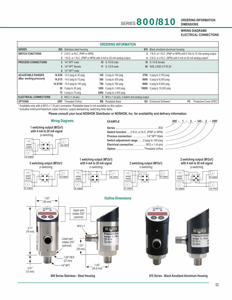
53
ORDERING INFORMATIONDIMENSIONS
WIRING DIAGRAMSELECTRICAL CONNECTIONS
Outline Dimensions
EXAMPLE
Series .............................................................800Switch function .... 2 N.O. or N.C. (PNP or NPN)Process connection ....................1/4″ NPT MaleSwitch adjustment range .......0 psig to 145 psigElectrical connection .................M12 x 1 (4-pin)Option ........................................ Threaded orifice
800 – 1 – 2 – 145 – 2 – ORF
ORDERING INFORMATIONSERIES 800 Stainless steel housing 810 Black anodized aluminum housingSWITCH FUNCTIONS 1 2 N.O. or N.C. (PNP or NPN) 3 1 N.O. or 1 N.C. (PNP or NPN) with 0 Vdc to 10 Vdc analog output
2 1 N.O. or 1 N.C. (PNP or NPN) with 4 mA to 20 mA analog output 4 2 N.O. or 2 N.C. (NPN) with 4 mA to 20 mA analog output*PROCESS CONNECTIONS 2 1/4″ NPT male 10 G 1/4 B male 19 G 1/4 B female
5 1/4″ NPT female 11 G 1/2 B male 45 SAE J1926-3:7/16-208 1/2″ NPT male
ADJUSTABLE RANGES(Max. working pressure)
14.5/30 -14.5 psig to 30 psig 145 0 psig to 145 psig 3750 0 psig to 3,750 psig14.5/75 -14.5 psig to 75 psig 300 0 psig to 300 psig 6000 0 psig to 6,000 psig
14.5/145 -14.5 psig to 145 psig 750 0 psig to 750 psig 9000 0 psig to 9,000 psig30 0 psig to 30 psig 1450 0 psig to 1,450 psig 10000 0 psig to 10,000 psig75 0 psig to 75 psig 2400 0 psig to 2,400 psig
ELECTRICAL CONNECTIONS 2 M12 x 1 (4-pin) 3 M12 x 1 (5-pin), 2 switch and analog outputOPTIONS ORF Threaded Orifice RB Rotatable Base EH Enhanced Software 1 PC Protective Cover (IP67)* Available only with a M12 x 1 (5-pin) connector. Rotatable base is not available on this option. 1 Includes minimum/maximum value memory, output dampening, switching time delay
Please consult your local NOSHOK Distributor or NOSHOK, Inc. for availability and delivery information.
SERIES 800/810
Wiring Diagrams
powersupply
S1 output
S2 output
sig. output
1 2
3
5
4powersupply
S1 output
S2 output
1 2
34
powersupply
S1 output
sig. output
1 2
34
powersupply
S1 output
sig. output
1 2
34powersupply
S1 output
S2 output
1 2
34
2 switching output (M12x1)p-switching
1 switching output (M12x1)with 4 mA to 20 mA signal
n-switching2 switching output (M12x1)
n-switching
1 switching output (M12x1)with 4 mA to 20 mA signal
p-switching
2 switching output (M12x1)with 4 mA to 20 mA signal
p-switching
810 Series - Black Anodized Aluminum Housing
1.42"(36 mm)
3.11"(79 mm)
0.51"(13 mm)
Lower partrotates 330°(optional)
1/4" NPT
1.06" HEX(27 mm)
Upper partrotates 330°
(optional)
1.10"(28 mm)
1.40"(35.6 mm)
M12 x 1
800 Series Stainless - Steel Housing
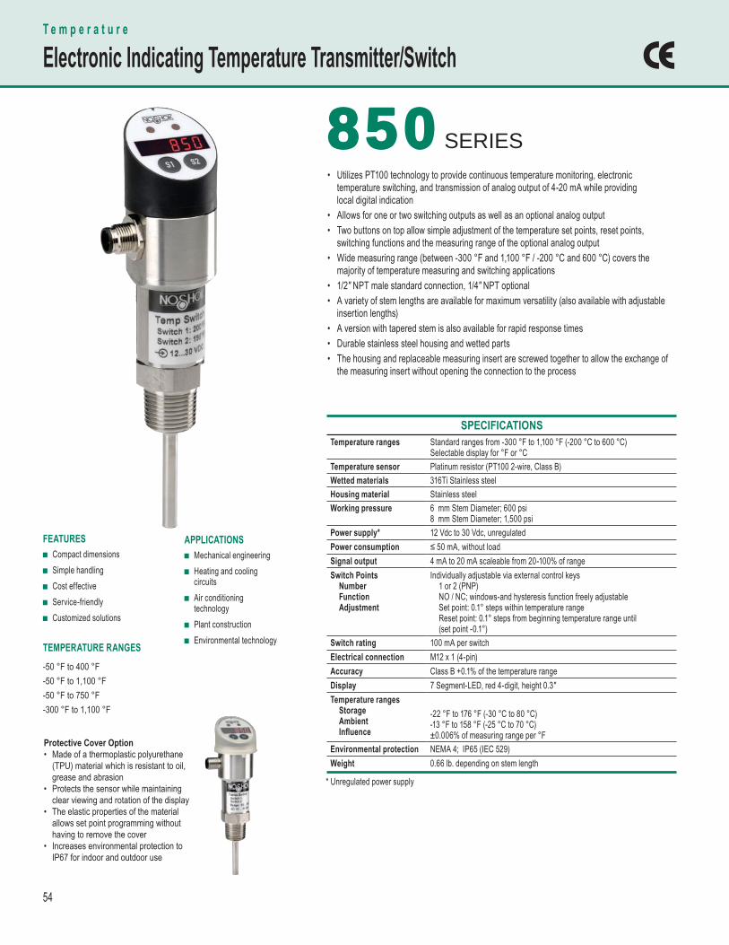
54
SPECIFICATIONS Temperature ranges Standard ranges from -300 °F to 1,100 °F (-200 °C to 600 °C)
Selectable display for °F or °C Temperature sensor Platinum resistor (PT100 2-wire, Class B)Wetted materials 316Ti Stainless steelHousing material Stainless steelWorking pressure 6 mm Stem Diameter; 600 psi
8 mm Stem Diameter; 1,500 psi Power supply* 12 Vdc to 30 Vdc, unregulatedPower consumption ≤ 50 mA, without loadSignal output 4 mA to 20 mA scaleable from 20-100% of range Switch Points Number Function Adjustment
Individually adjustable via external control keys 1 or 2 (PNP) NO / NC; windows-and hysteresis function freely adjustable Set point: 0.1° steps within temperature range Reset point: 0.1° steps from beginning temperature range until (set point -0.1°)
Switch rating 100 mA per switchElectrical connection M12 x 1 (4-pin)Accuracy Class B +0.1% of the temperature rangeDisplay 7 Segment-LED, red 4-digit, height 0.3"Temperature ranges Storage Ambient Infl uence
-22 °F to 176 °F (-30 °C to 80 °C) -13 °F to 158 °F (-25 °C to 70 °C) ±0.006% of measuring range per °F
Environmental protection NEMA 4; IP65 (IEC 529)Weight 0.66 lb. depending on stem length
APPLICATIONS ■ Mechanical engineering ■ Heating and cooling
circuits ■ Air conditioning
technology ■ Plant construction ■ Environmental technology
FEATURES ■ Compact dimensions ■ Simple handling ■ Cost effective ■ Service-friendly ■ Customized solutions
TEMPERATURE RANGES -50 °F to 400 °F-50 °F to 1,100 °F-50 °F to 750 °F-300 °F to 1,100 °F
850850 SERIES• Utilizes PT100 technology to provide continuous temperature monitoring, electronic temperature switching, and transmission of analog output of 4-20 mA while providing local digital indication• Allows for one or two switching outputs as well as an optional analog output• Two buttons on top allow simple adjustment of the temperature set points, reset points, switching functions and the measuring range of the optional analog output• Wide measuring range (between -300 °F and 1,100 °F / -200 °C and 600 °C) covers the majority of temperature measuring and switching applications• 1/2" NPT male standard connection, 1/4" NPT optional• A variety of stem lengths are available for maximum versatility (also available with adjustable insertion lengths)• A version with tapered stem is also available for rapid response times• Durable stainless steel housing and wetted parts• The housing and replaceable measuring insert are screwed together to allow the exchange of the measuring insert without opening the connection to the process
T e m p e r a t u r e
Electronic Indicating Temperature Transmitter/Switch
* Unregulated power supply
Protective Cover Option• Made of a thermoplastic polyurethane
(TPU) material which is resistant to oil, grease and abrasion
• Protects the sensor while maintaining clear viewing and rotation of the display
• The elastic properties of the material allows set point programming without having to remove the cover
• Increases environmental protection to IP67 for indoor and outdoor use
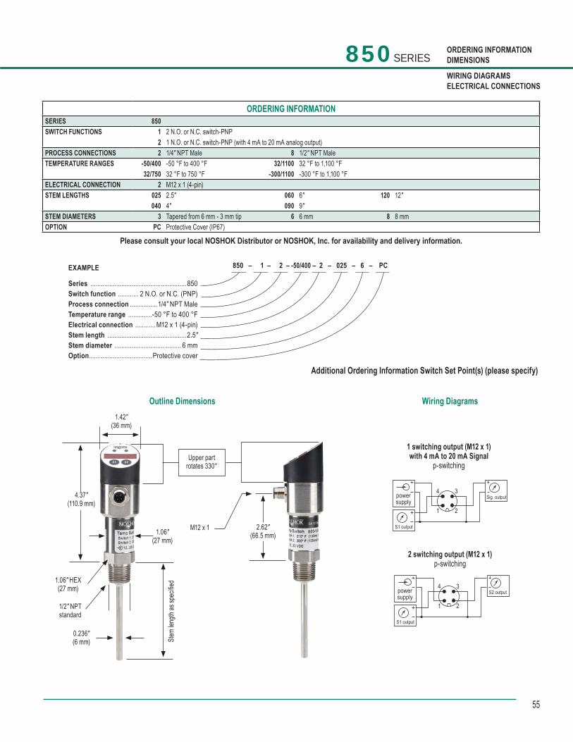
55
850 SERIES ORDERING INFORMATIONDIMENSIONS
WIRING DIAGRAMSELECTRICAL CONNECTIONS
Additional Ordering Information Switch Set Point(s) (please specify)
Outline Dimensions
1 switching output (M12 x 1)with 4 mA to 20 mA Signal
p-switching
2 switching output (M12 x 1)p-switching
Wiring Diagrams
1.06" HEX(27 mm)
1/2" NPTstandard
4.37"(110.9 mm)
1.06"(27 mm)
2.62"(66.5 mm)
M12 x 1
0.236"(6 mm)
Upper partrotates 330°
Stem
leng
th as
spec
ified
1.42"(36 mm)
ORDERING INFORMATIONSERIES 850 SWITCH FUNCTIONS 1 2 N.O. or N.C. switch-PNP
2 1 N.O. or N.C. switch-PNP (with 4 mA to 20 mA analog output) PROCESS CONNECTIONS 2 1/4″ NPT Male 8 1/2″ NPT MaleTEMPERATURE RANGES -50/400 -50 °F to 400 °F 32/1100 32 °F to 1,100 °F
32/750 32 °F to 750 °F -300/1100 -300 °F to 1,100 °FELECTRICAL CONNECTION 2 M12 x 1 (4-pin) STEM LENGTHS 025 2.5″ 060 6″ 120 12″
040 4″ 090 9″STEM DIAMETERS 3 Tapered from 6 mm - 3 mm tip 6 6 mm 8 8 mmOPTION PC Protective Cover (IP67)
Please consult your local NOSHOK Distributor or NOSHOK, Inc. for availability and delivery information.
EXAMPLE
Series ........................................................ 850Switch function ............ 2 N.O. or N.C. (PNP)Process connection ................1/4″ NPT MaleTemperature range .............. -50 °F to 400 °FElectrical connection ............ M12 x 1 (4-pin)Stem length .............................................. 2.5″Stem diameter ....................................... 6 mmOption .....................................Protective cover
850 – 1 – 2 – -50/400 – 2 – 025 – 6 – PC
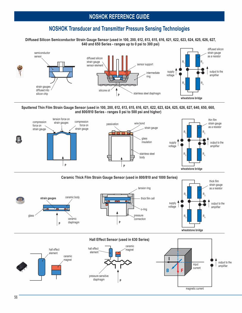
56
NOSHOK Transducer and Transmitter Pressure Sensing Technologies
Sputtered Thin Film Strain Gauge Sensor (used in 100, 200, 612, 613, 615, 616, 621, 622, 623, 624, 625, 626, 627, 640, 650, 660, and 800/810 Series - ranges 0 psi to 500 psi and higher)
Diffused Silicon Semiconductor Strain Gauge Sensor (used in 100, 200, 612, 613, 615, 616, 621, 622, 623, 624, 625, 626, 627, 640 and 650 Series - ranges up to 0 psi to 300 psi)
semiconductorsensor
strain gaugesdiffused intosilicon chip
diffused siliconstrain gaugesensor element
s ilicone oil
sensor support
intermediatering
stainless steel diaphragmP
output to theamplifier
wheatstone bridge
supplyvoltage
diffused silicon strain gaugeas a resistor
output to theamplifier
wheatstone bridge
supplyvoltage
thin filmstrain gaugeas a resistor
R1 R2
R3 R4
R1 R2
R3 R4
Ceramic Thick Film Strain Gauge Sensor (used in 800/810 and 1000 Series)
output to theamplifier
wheatstone bridge
supplyvoltage
thick filmstrain gaugeas a resistor
R1 R2
R3 R4
strain gauges ceramic body
ceramicdiaphragm
glass
P
pressureconnection
P
o-ring
tension ring
thick film cell
compressionforce onstrain gauge
passivationstrain gauge
glass insulation
stainless steelbody
P
wire bond
P
tension force onstrain gauges compression
force onstrain gauge
Hall Effect Sensor (used in 630 Series)
inputcurrent
magnetic current
output to theamplifier
ceramicmagnet
P
hall effectelement
pressure sensitivediaphragm
ceramicmagnet
hall effect element
NOSHOK REFERENCE GUIDE
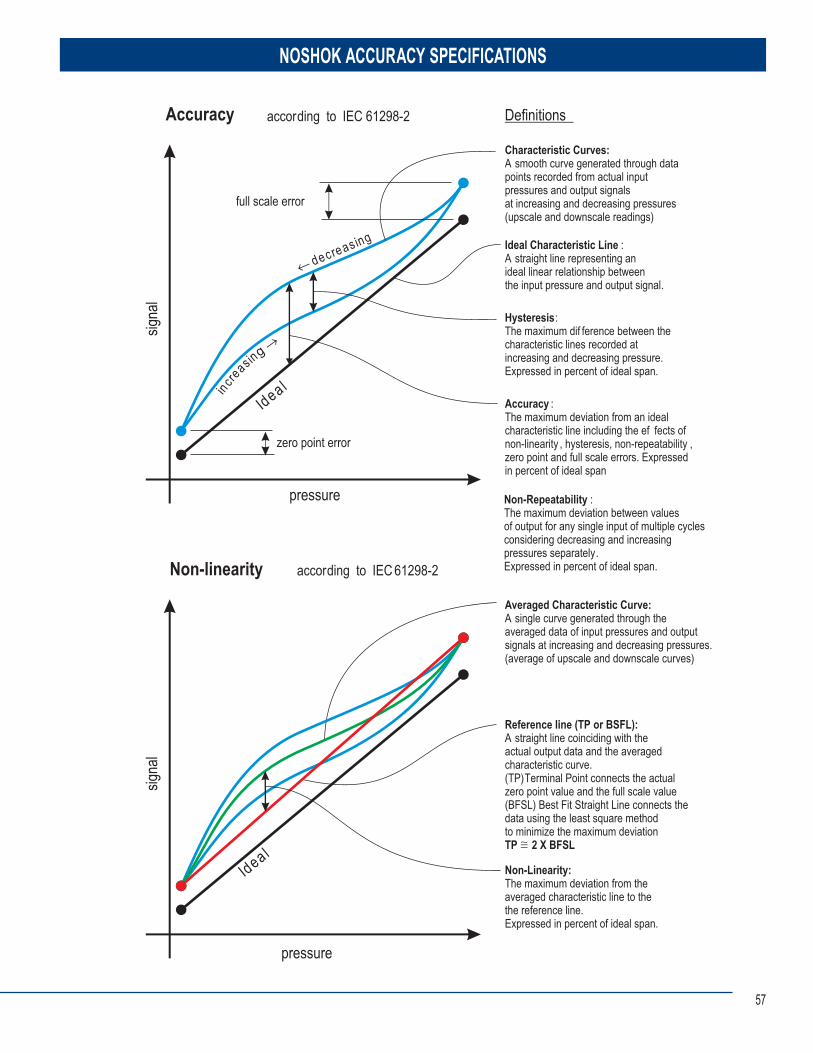
57
NOSHOK ACCURACY SPECIFICATIONS
Accuracy according to IEC 61298-2
Hysteresis:The maximum dif ference between thecharacteristic lines recorded atincreasing and decreasing pressure.Expressed in percent of ideal span.
Accuracy :The maximum deviation from an idealcharacteristic line including the ef fects ofnon-linearity , hysteresis, non-repeatability ,zero point and full scale errors. Expressedin percent of ideal span
Non-Repeatability :The maximum deviation between values of output for any single input of multiple cyclesconsidering decreasing and increasingpressures separately. Expressed in percent of ideal span.
Non-Linearity:The maximum deviation from theaveraged characteristic line to thethe reference line.Expressed in percent of ideal span.
Ideal Characteristic Line :A straight line representing anideal linear relationship betweenthe input pressure and output signal.
Characteristic Curves:A smooth curve generated through data points recorded from actual inputpressures and output signalsat increasing and decreasing pressures(upscale and downscale readings)
Averaged Characteristic Curve:A single curve generated through theaveraged data of input pressures and outputsignals at increasing and decreasing pressures.(average of upscale and downscale curves)
gnisaerced
nisaercni laedI
laedI
Non-linearity according to IEC 61298-2
Definitions
signa
lsig
nal
pressure
pressure
Reference line (TP or BSFL):A straight line coinciding with the actual output data and the averagedcharacteristic curve.(TP) Terminal Point connects the actualzero point value and the full scale value(BFSL) Best Fit Straight Line connects thedata using the least square methodto minimize the maximum deviationTP 2 X BFSL
zero point error
full scale error
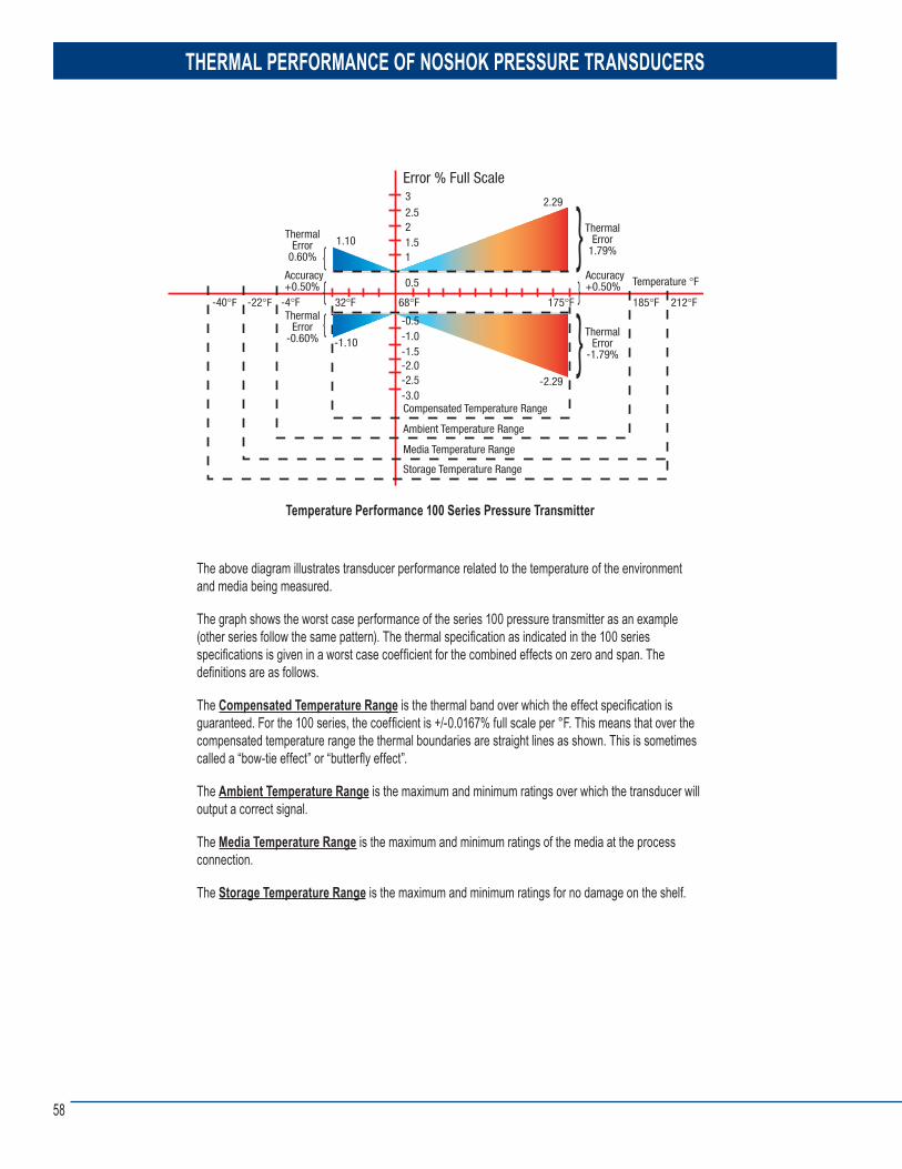
58
THERMAL PERFORMANCE OF NOSHOK PRESSURE TRANSDUCERS
The above diagram illustrates transducer performance related to the temperature of the environment and media being measured.
The graph shows the worst case performance of the series 100 pressure transmitter as an example (other series follow the same pattern). The thermal specifi cation as indicated in the 100 series specifi cations is given in a worst case coeffi cient for the combined effects on zero and span. The defi nitions are as follows.
The Compensated Temperature Range is the thermal band over which the effect specifi cation is guaranteed. For the 100 series, the coeffi cient is +/-0.0167% full scale per °F. This means that over the compensated temperature range the thermal boundaries are straight lines as shown. This is sometimes called a “bow-tie effect” or “butterfl y effect”.
The Ambient Temperature Range is the maximum and minimum ratings over which the transducer will output a correct signal.
The Media Temperature Range is the maximum and minimum ratings of the media at the process connection.
The Storage Temperature Range is the maximum and minimum ratings for no damage on the shelf.
Temperature Performance 100 Series Pressure Transmitter
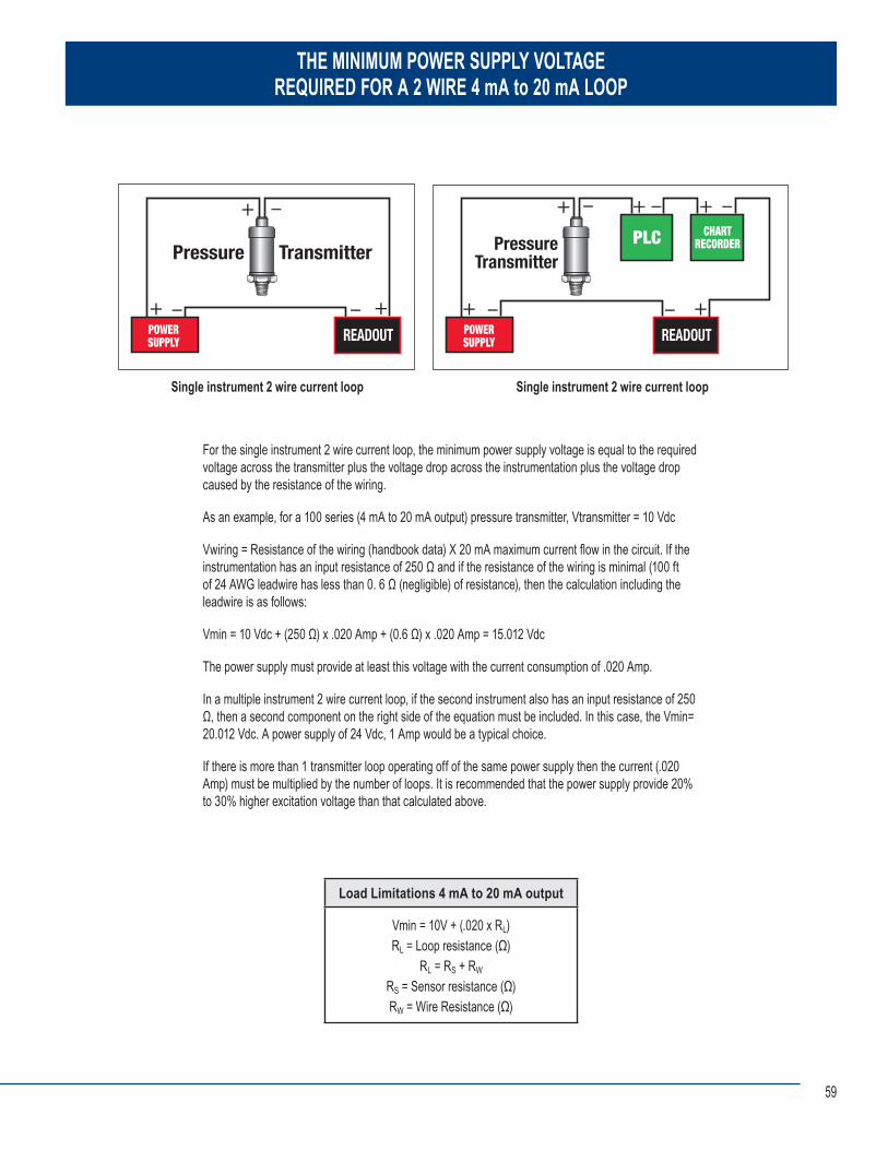
59
THE MINIMUM POWER SUPPLY VOLTAGEREQUIRED FOR A 2 WIRE 4 mA to 20 mA LOOP
For the single instrument 2 wire current loop, the minimum power supply voltage is equal to the required voltage across the transmitter plus the voltage drop across the instrumentation plus the voltage drop caused by the resistance of the wiring.
As an example, for a 100 series (4 mA to 20 mA output) pressure transmitter, Vtransmitter = 10 Vdc
Vwiring = Resistance of the wiring (handbook data) X 20 mA maximum current fl ow in the circuit. If the instrumentation has an input resistance of 250 Ω and if the resistance of the wiring is minimal (100 ft of 24 AWG leadwire has less than 0. 6 Ω (negligible) of resistance), then the calculation including the leadwire is as follows:
Vmin = 10 Vdc + (250 Ω) x .020 Amp + (0.6 Ω) x .020 Amp = 15.012 Vdc
The power supply must provide at least this voltage with the current consumption of .020 Amp.
In a multiple instrument 2 wire current loop, if the second instrument also has an input resistance of 250 Ω, then a second component on the right side of the equation must be included. In this case, the Vmin= 20.012 Vdc. A power supply of 24 Vdc, 1 Amp would be a typical choice.
If there is more than 1 transmitter loop operating off of the same power supply then the current (.020 Amp) must be multiplied by the number of loops. It is recommended that the power supply provide 20% to 30% higher excitation voltage than that calculated above.
Single instrument 2 wire current loop Single instrument 2 wire current loop
Load Limitations 4 mA to 20 mA output
Vmin = 10V + (.020 x RL)RL = Loop resistance (Ω)
RL = RS + RW
RS = Sensor resistance (Ω)RW = Wire Resistance (Ω)
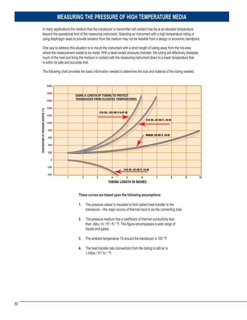
60
MEASURING THE PRESSURE OF HIGH TEMPERATURE MEDIA In many applications the medium that the transducer or transmitter will contact may be at an elevated temperature beyond the operational limit of the measuring instrument. Selecting an instrument with a high temperature rating or using diaphragm seals to provide isolation from the medium may not be feasible from a design or economic standpoint.
One way to address this situation is to mount the instrument with a short length of tubing away from the hot areawhere the measurement needs to be made. With a dead ended pressure chamber, the tubing will effectively dissipate much of the heat and bring the medium in contact with the measuring instrument down to a lower temperature that is within its safe and accurate limit.
The following chart provides the basic information needed to determine the size and material of the tubing needed.
These curves are based upon the following assumptions:
1. The pressure vessel is insulated to limit radiant heat transfer to the transducer – the major source of thermal input is via the connecting tube.
2. The pressure medium has a coeffi cient of thermal conductivity less than .4btu / hr / ft2 / ft / °F. This fi gure encompasses a wide range of liquids and gases.
3. The ambient temperature TA around the transducer is 100 °F.
4. The heat transfer rate (convection) from the tubing to still air is 1.44btu / ft2 / hr / °F.
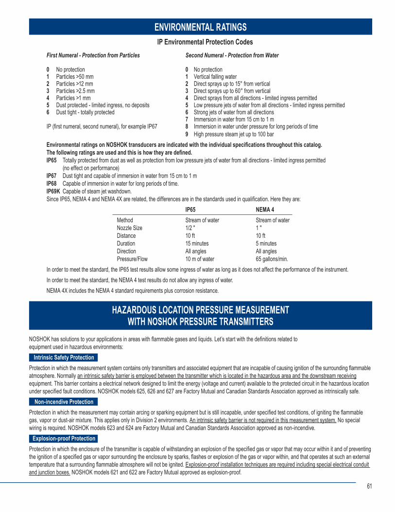
61
ENVIRONMENTAL RATINGS
HAZARDOUS LOCATION PRESSURE MEASUREMENTWITH NOSHOK PRESSURE TRANSMITTERS
IP Environmental Protection CodesFirst Numeral - Protection from Particles Second Numeral - Protection from Water
0 No protection 0 No protection1 Particles >50 mm 1 Vertical falling water2 Particles >12 mm 2 Direct sprays up to 15° from vertical3 Particles >2.5 mm 3 Direct sprays up to 60° from vertical4 Particles >1 mm 4 Direct sprays from all directions - limited ingress permitted5 Dust protected - limited ingress, no deposits 5 Low pressure jets of water from all directions - limited ingress permitted6 Dust tight - totally protected 6 Strong jets of water from all directions 7 Immersion in water from 15 cm to 1 mIP (fi rst numeral, second numeral), for example IP67 8 Immersion in water under pressure for long periods of time 9 High pressure steam jet up to 100 bar Environmental ratings on NOSHOK transducers are indicated with the individual specifi cations throughout this catalog. The following ratings are used and this is how they are defi ned.IP65 Totally protected from dust as well as protection from low pressure jets of water from all directions - limited ingress permitted (no effect on performance)IP67 Dust tight and capable of immersion in water from 15 cm to 1 mIP68 Capable of immersion in water for long periods of time.IP69K Capable of steam jet washdown.Since IP65, NEMA 4 and NEMA 4X are related, the differences are in the standards used in qualifi cation. Here they are: IP65 NEMA 4 Method Stream of water Stream of water Nozzle Size 1/2 ″ 1 ″ Distance 10 ft 10 ft Duration 15 minutes 5 minutes Direction All angles All angles Pressure/Flow 10 m of water 65 gallons/min.In order to meet the standard, the IP65 test results allow some ingress of water as long as it does not affect the performance of the instrument.In order to meet the standard, the NEMA 4 test results do not allow any ingress of water.NEMA 4X includes the NEMA 4 standard requirements plus corrosion resistance.
NOSHOK has solutions to your applications in areas with fl ammable gases and liquids. Let’s start with the defi nitions related to equipment used in hazardous environments: Intrinsic Safety ProtectionProtection in which the measurement system contains only transmitters and associated equipment that are incapable of causing ignition of the surrounding fl ammable atmosphere. Normally an intrinsic safety barrier is employed between the transmitter which is located in the hazardous area and the downstream receiving equipment. This barrier contains a electrical network designed to limit the energy (voltage and current) available to the protected circuit in the hazardous location under specifi ed fault conditions. NOSHOK models 625, 626 and 627 are Factory Mutual and Canadian Standards Association approved as intrinsically safe. Non-incendive ProtectionProtection in which the measurement may contain arcing or sparking equipment but is still incapable, under specifi ed test conditions, of igniting the fl ammable gas, vapor or dust-air mixture. This applies only in Division 2 environments. An intrinsic safety barrier is not required in this measurement system. No special wiring is required. NOSHOK models 623 and 624 are Factory Mutual and Canadian Standards Association approved as non-incendive. Explosion-proof ProtectionProtection in which the enclosure of the transmitter is capable of withstanding an explosion of the specifi ed gas or vapor that may occur within it and of preventing the ignition of a specifi ed gas or vapor surrounding the enclosure by sparks, fl ashes or explosion of the gas or vapor within, and that operates at such an external temperature that a surrounding fl ammable atmosphere will not be ignited. Explosion-proof installation techniques are required including special electrical conduit and junction boxes. NOSHOK models 621 and 622 are Factory Mutual approved as explosion-proof.
62
HAZARDOUS LOCATION CLASSIFICATIONS (NEC)
WHY NOSHOK IS THE BEST CHOICE
Class I: Areas in which fl ammable gases or vapors may be present in the air in suffi cient quantities to be explosiveGroup A: Atmospheres containing acetyleneGroup B: Atmospheres such as butadiene, ethylene oxide, propylene oxide, acrolein, or hydrogen (gases or vapors equivalent in hazard to hydrogen, such as manufactured gas)Group C: Atmospheres such as cyclopropane, ethyl ether, ethylene, gas or vapors of equivalent hazardGroup D: Atmospheres such as acetone, alcohol, ammonia, benzene, benzol, butane, gasoline, hexane, lacquer solvent vapors, naphtha, natural gas, propane, or gas or vapors of equivalent hazardClass II: Areas made hazardous by the presence of combustible dustGroup E: Atmospheres containing combustible metal dusts, regardless of resistivity; dust of similarly hazardous characteristics having a resistivity of less than 100 KΩs-cm; electrically conductive dustsGroup F: Atmospheres containing combustible carbon black, charcoal, or coke dusts having more than 8% total volatile material; dusts so sensitized that they present an explosion hazard, and dusts having a resistivity of greater than 100 Ω-cm but less than or equal to 1x10⁸ Ω-cmGroup G: Atmospheres containing combustible dust having resistivity equal to or greater than 100K Ω-cm; electrically nonconductive dustsClass III: Areas made hazardous by the presence of easily ignitable fi bers or dust, but which are not likely to be in suspension in the air in quantitiesthat are suffi cient to igniteDivision 1: Atmospheres where hazardous concentrations exist continuously, intermittently or periodically under normal operating conditionsDivision 2: Atmospheres where hazardous concentrations exist only in case of accidental rupture or breakdown of equipment
■ Stable sensing technologies mean that there is no need for periodic recalibration. NOSHOK transducers do not have glues, epoxies or adhesives in the transduction portion of the sensor module because such organic agents cause calibration drift with temperature and pressure cycling, and over time in some applications, cause complete failure.
■ Broad product offering results in best fit of product configuration to customer application requirements. ■ CE compliance and an environmentally hardened design mean maximum performance and reliability in difficult real world applications.
Products are manufactured in an ISO 9001 certified facility. ■ All product specifications are conservatively stated in the literature so that product performance exceeds customer expectations. ■ No specsmanship or games are ever employed, only honest information. ■ The calibration of every product is verified in NOSHOK’s modern facility with the best available pressure controllers and computerized readout equipment
that are at least 4 times the accuracy of the product being checked. ■ Highly automated production minimizing the variations in product caused by human labor mean more consistency from unit to unit resulting in
interchangeability and consistent performance. ■ Simple and proven dc electronics improves reliability and longer mean time between failure (MTBF) characteristics. ■ While field failures are few, NOSHOK backs it’s electronic products with a 3-year warranty that is the best in the market. ■ Products provide significant performance and application flexibility at competitive prices addressing the needs of the OEM and the user alike. ■ As a privately owned and run business, NOSHOK employees focus on continually improving customer satisfaction.
Specsmanship - What to Look for in Comparing Other Transducers and Transmitters to NOSHOK Products
■ Be on the lookout for suppliers specifying “high accuracy” with a low price. In many cases you will find indications of zero offsets and span offsets of up to 2% each. The specified accuracy of NOSHOK transducers includes any offsets and is a true accuracy upon which you can depend.
■ If the competitors do not specify a long term stability specification, then this bears out our contention that many of these other sensing technologies do not yield an attractive stability specification otherwise it would be printed in the literature.
■ Look out for the “typical” nomenclature or the Root-Sum-Square (RSS) designation. While these methods provide a statistical probability of how most of the products will perform, it means that if a quantity of units is considered then a percentage of the products will not meet the listed specification. NOSHOK specifications are worst case, so all the transducers meet that specification.
63
FREQUENTLY ASKED QUESTIONS
Q. What is the difference between a transducer and transmitter? A. When these terms originated there was a distinctive difference between the two. A transmitter was referred to as an instrument with a current output signal (i.e. 4 mA to 20 mA) and a transducer was referred to as an instrument with a voltage signal (i.e. 3 mV/V, 0 Vdc to 10 Vdc etc.). As time has progressed these terms are now commonly interchanged for reference to current, voltage and digital output signals.
Q. What is the difference between the proof pressure and burst pressure specifi cations? A. Proof pressure which is higher than the full scale pressure point is the limit that you can go to without affecting the performance and calibration of the transducer. The burst pressure on the other hand is the limit that you can go before there is pressure chamber rupture and damage. An overload limit specifi cation used sometimes means that proof and burst ratings are identical.
Q. Will the series 1800 Attachable Loop Indicator work with transmitters not made by NOSHOK? A. The series 1800 indicator will work with any brand that has the same pin connections and style Hirschmann connector and suffi cient power supply voltage to drive all instruments in the loop. The series 1800 will use 3 Vdc to operate.
Q. What does RFI, EMI and ESD mean related to pressure transducers and transmitter? A. Radio Frequency Interference and Electromagnetic Interference refer to the effects electrical noise can have on instruments. RFI frequently comes from hand held walkie-talkies and EMI comes from AC motors in the vicinity of the instrument. ESD (Electrostatic Discharge) comes from many sources including the application itself. CE compliant transmitters and transducers incorporate protection techniques and components to minimize most of the interference. Q. Can traditional diaphragm seals or gauge protectors be used with pressure transducers and transmitters? A. Most diaphragm seals can be used with pressure transducers and transmitters. The real key is to assemble and fi ll the seal properly, being careful not to entrap air in the fi ll fl uid.
Q. Are pigtail steam syphons used in transmitter applications? A. The steam syphon is necessary in steam pressure applications. It is important to isolate the transmitter sensing diaphragm from the high temperature encountered with steam pressure applications.
Q. Can orifi ces and snubbers be used and why would they be needed? A. As with other pressure measurement instruments including gauges, pressure pulsations and spikes, are issues with pressure transmitters. Whenever the pressure of an incompressible fl uid is measured, there is the potential for pulsations and spikes, which can damage pressure transmitters. An orifi ce installed in the pressure connection by NOSHOK can protect the transmitter from damage. Where there is the possibility of clogging the small orifi ce, an attachable piston snubber is recommended.
Q. What is the reason for the vent tube in the cable of the model 612 and 627 submersible level transmitters? A. All pressure measurements are inherently differential in theory. Gauge pressure is referenced to ambient atmospheric, absolute pressure is referenced to vacuum contained in an evacuated chamber within the transmitter. The level measurement is also a differential measurement, with its reference to ambient atmospheric pressure. In order for the submersible level measurement to be referenced to atmospheric, the cable contains a vent tube which runs the complete length of the cable and “vents” into the atmospheric pressure at the junction box connection which is out of the liquid.
Q. How does the series 612 and 627 submersible level transmitter measure level? A. The transmitter measures the hydrostatic pressure produced by the liquid level higher than the point where the instrument is located. The higher the liquid, the higher the pressure. Q. NOSHOK transducers and transmitters are normally 2 wire or 3 wire in output confi guration. Is a 4 wire transducer available? A. Voltage output transducers are available with a 4th connection which is electrically the same as the power supply common to connect to wiring confi gurations that require it.
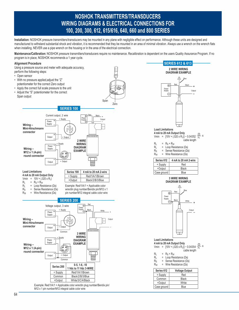
64
NOSHOK TRANSMITTERS/TRANSDUCERSWIRING DIAGRAMS & ELECTRICAL CONNECTIONS FOR
100, 200, 300, 612, 615/616, 640, 660 and 800 SERIES Installation: NOSHOK pressure transmitters/transducers may be mounted in any plane with negligible effect on performance. Although these units are designed and manufactured to withstand substantial shock and vibration, it is recommended that they be mounted in an area of minimal vibration. Always use a wrench on the wrench fl ats when installing. NEVER use a pipe wrench on the housing or in the area of the electrical connection.Maintenance/Calibration: NOSHOK pressure transmitters/transducers require no maintenance. Recalibration is dependent on the users Quality Assurance Program. If no program is in place, NOSHOK recommends a 1 year cycle.Alignment ProcedureUsing a pressure source and meter with adequate accuracy, perform the following steps: • Open sensor• With no pressure applied,adjust the “Z” potentiometer for the correct Zero output• Apply the correct full scale pressure to the unit• Adjust the “S” potentiometer for the correct Span output
2 WIRE WIRING
DIAGRAM EXAMPLE
Output PowerSupply
BlackRedCurrent output, 2 wire
PowerSupply
+ Supply
+ OutputOutput
1
3 2
PowerSupply
+ Supply
+ OutputOutput
Load Limitations 4 mA to 20 mA Output OnlyVmin = 10V + (.020 x RL) RL = RS + RWRL = Loop Resistance (Ωs)RS = Sense Resistance (Ωs)RW = Wire Resistance (Ωs)
Example: Red/1/A/1 = Applicable color wire/din plug number/Bendix pin/M12 x 1 pin number/M12 integral cable color wire
Series 100 4 mA to 20 mA 2-wire+ Supply Red/1/A/1/Brown+Output Black/2/B/3/Blue
SERIES 100
Wiring –Mini-Hirschmannconnector
Wiring –M12 x 1 (4-pin)round connector
2 WIRE WIRING DIAGRAM EXAMPLE
3 WIRE WIRING
DIAGRAM EXAMPLE
Black
Output
PowerSupply
Red
White
Voltage output, 3 wire+ Supply
+ Output
Common
Output
rPoweSupply
1
3
1
3 2
+ Supply
+ Output
Common
PowerSupply
Output •
•
•
Example: Red/1/A/1 = Applicable color wire/din plug number/Bendix pin/M12 x 1 pin number/M12 integral cable color wire
Series 200 0-5, 1-6, -101 Vdc to 11 Vdc 3-WIRE
+ Supply Red/1/A/1/BrownCommon Black/2/B/3/Blue+Output White/3/C/4/Black
SERIES 200
Wiring –Mini-Hirschmannconnector
Wiring –M12 x 1 (4-pin)round connector
3 WIRE WIRING DIAGRAM EXAMPLE
Black
Output
Red
PowerSupply
Blue
SERIES 612 & 613
Load Limitations 4 mA to 20 mA Output OnlyVmin = [10V + (.020 x RL)] − 0.04352
cable lengthRL = RS + RWRL = Loop Resistance (Ωs)RS = Sense Resistance (Ωs)RW = Wire Resistance (Ωs)
Series 612 4 mA to 20 mA 2-wire+ Supply Red+Output Black
Case ground Blue
2 WIRE WIRING DIAGRAM EXAMPLE
SpanZero
PowerSupply
Red Blue
Black White•
Output
3 WIRE WIRING DIAGRAM EXAMPLE
Load Limitations 4 mA to 20 mA Output OnlyVmin = [10V + (.020 x RL)] − 0.04354
cable lengthRL = RS + RWRL = Loop Resistance (Ωs)RS = Sense Resistance (Ωs)RW = Wire Resistance (Ωs)
Series 612 Voltage Output+ Supply RedCommon Black+Output White
Case ground Blue
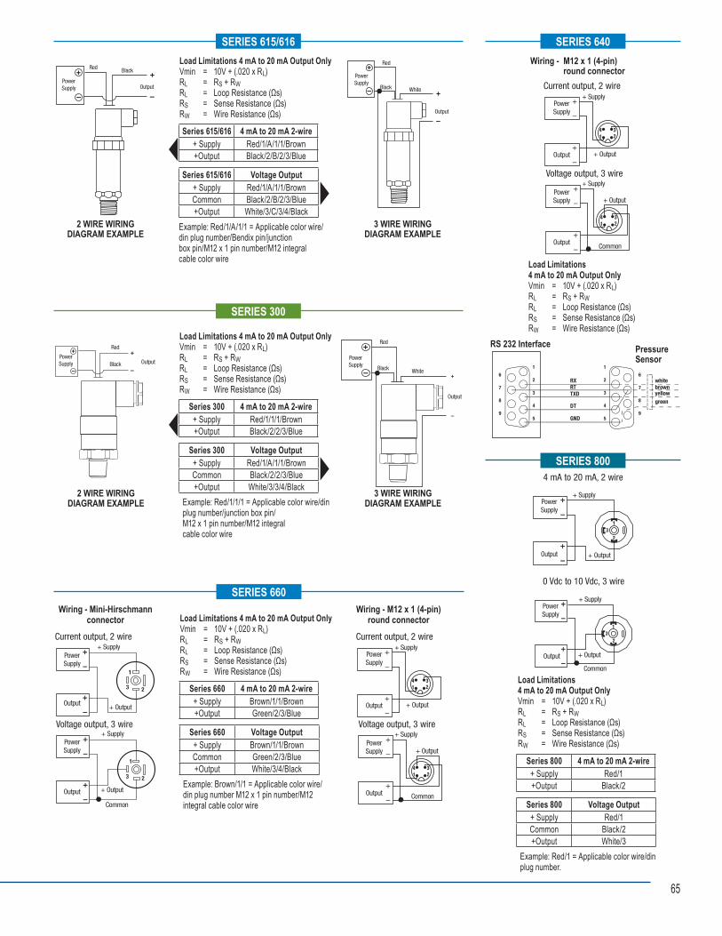
65
Red Black
PowerSupply Output
Load Limitations 4 mA to 20 mA Output OnlyVmin = 10V + (.020 x RL) RL = RS + RWRL = Loop Resistance (Ωs)RS = Sense Resistance (Ωs)RW = Wire Resistance (Ωs)
Example: Red/1/A/1/1 = Applicable color wire/din plug number/Bendix pin/junction box pin/M12 x 1 pin number/M12 integral cable color wire
SERIES 615/616
2 WIRE WIRINGDIAGRAM EXAMPLE
Series 615/616 4 mA to 20 mA 2-wire+ Supply Red/1/A/1/1/Brown+Output Black/2/B/2/3/Blue
Series 615/616 Voltage Output+ Supply Red/1/A/1/1/BrownCommon Black/2/B/2/3/Blue+Output White/3/C/3/4/Black
Red
Black White
PowerSupply
Output
•
3 WIRE WIRINGDIAGRAM EXAMPLE
Voltage output, 3 wire
Current output, 2 wire
PowerSupply
+ Supply
+ Supply
+ Output
+ Output
Common
Output
Output
PowerSupply
•
SERIES 640
Load Limitations 4 mA to 20 mA Output OnlyVmin = 10V + (.020 x RL) RL = RS + RWRL = Loop Resistance (Ωs)RS = Sense Resistance (Ωs)RW = Wire Resistance (Ωs)
1
2
3
4
5
1
2
3
4
5
6
7
8
9
6
7
8
9
RX whitebrownyellow
RTTXD
DT
GND
green
Pressure Sensor
PressureSensor
RS 232 Interface
Wiring - M12 x 1 (4-pin) round connector
Red
BlackPowerSupply Output
SERIES 300
2 WIRE WIRINGDIAGRAM EXAMPLE
3 WIRE WIRINGDIAGRAM EXAMPLE
Load Limitations 4 mA to 20 mA Output OnlyVmin = 10V + (.020 x RL) RL = RS + RWRL = Loop Resistance (Ωs)RS = Sense Resistance (Ωs)RW = Wire Resistance (Ωs)
Series 300 4 mA to 20 mA 2-wire+ Supply Red/1/1/1/Brown+Output Black/2/2/3/Blue
Series 300 Voltage Output+ Supply Red/1/A/1/1/BrownCommon Black/2/2/3/Blue+Output White/3/3/4/Black
Example: Red/1/1/1 = Applicable color wire/din plug number/junction box pin/M12 x 1 pin number/M12 integral cable color wire
Red
Black White
PowerSupply
Output
•
SERIES 660
Current output, 2 wire
Voltage output, 3 wire
PowerSupply
+ Supply
+ Supply
+ Output
+ Output
Common
Output
Output
PowerSupply
1
3 2
1
3 2
•
Load Limitations 4 mA to 20 mA Output OnlyVmin = 10V + (.020 x RL) RL = RS + RWRL = Loop Resistance (Ωs)RS = Sense Resistance (Ωs)RW = Wire Resistance (Ωs)
Series 660 4 mA to 20 mA 2-wire+ Supply Brown/1/1/Brown+Output Green/2/3/Blue
Series 660 Voltage Output+ Supply Brown/1/1/BrownCommon Green/2/3/Blue+Output White/3/4/Black
Example: Brown/1/1 = Applicable color wire/din plug number M12 x 1 pin number/M12 integral cable color wire
Wiring - Mini-Hirschmann connector
Voltage output, 3 wire
Current output, 2 wire
PowerSupply
+ Supply
+ Supply
+ Output
+ Output
Common
Output
Output
PowerSupply
•
Wiring - M12 x 1 (4-pin) round connector
4 mA to 20 mA, 2 wire
0 Vdc to 10 Vdc, 3 wire
+ Supply
+ Output
PowerSupply
Output
+ Supply
+ Output
Common
PowerSupply
Output•
SERIES 800
Load Limitations 4 mA to 20 mA Output OnlyVmin = 10V + (.020 x RL) RL = RS + RWRL = Loop Resistance (Ωs)RS = Sense Resistance (Ωs)RW = Wire Resistance (Ωs)
Series 800 4 mA to 20 mA 2-wire+ Supply Red/1+Output Black/2
Series 800 Voltage Output+ Supply Red/1Common Black/2+Output White/3
Example: Red/1 = Applicable color wire/din plug number.

666666
NOTES____________________________________________________________________________________
____________________________________________________________________________________
____________________________________________________________________________________
____________________________________________________________________________________
____________________________________________________________________________________
____________________________________________________________________________________
____________________________________________________________________________________
____________________________________________________________________________________
____________________________________________________________________________________
____________________________________________________________________________________
____________________________________________________________________________________
____________________________________________________________________________________
____________________________________________________________________________________
____________________________________________________________________________________
____________________________________________________________________________________
____________________________________________________________________________________
____________________________________________________________________________________
____________________________________________________________________________________
____________________________________________________________________________________
____________________________________________________________________________________
____________________________________________________________________________________

676767
TO DOWNLOAD OR ORDER OUR CATALOGS, VISIT WWW.NOSHOK.COM
NOSHOK is committed to providing
a high degree of value and continually improving processes to improve customer
satisfaction by focusing on customer requirements for the design, manufacture and distribution of pressure, temperature,
and force measurement instruments along with needle and
manifold valves.
Quality Policy
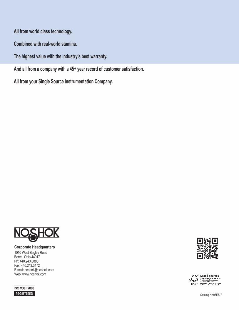
All from world class technology.
Combined with real-world stamina.
The highest value with the industry’s best warranty.
And all from a company with a 45+ year record of customer satisfaction.
All from your Single Source Instrumentation Company.
Catalog NK08ES-7
Corporate Headquarters1010 West Bagley RoadBerea, Ohio 44017Ph: 440.243.0888Fax: 440.243.3472E-mail: [email protected]: www.noshok.com


![High Purity Regulators - Emerson Electric€¦ · • Cv = .15 600 PSIG [41 bar] 30, 60, 100 PSIG [2, 4, 7 bar]](https://img.pdfslide.net/doc/110x75/5edc2160ad6a402d6666aa9f/high-purity-regulators-emerson-electric-a-cv-15-600-psig-41-bar-30-60.jpg)


![Pressure switches and Thermostats, type KP€¦ · Type Range [psig] Differential [psi] Reset Pressure connection Max. operat-ing pressure [psig] Min. burst pressure [psig] Code nos](https://img.pdfslide.net/doc/110x75/5e286d5dcd347d7fa07fa52f/pressure-switches-and-thermostats-type-kp-type-range-psig-differential-psi.jpg)