Embed Size (px)
Citation preview
Electronic Multi-Measuring Instrument
MODEL
ME96SSHB-MB User's Manual: Detailed Edition
Before use, you should read this user’s manual carefully
to properly operate this instrument. Be sure to forward the manual to the end user.
1
Check your delivery
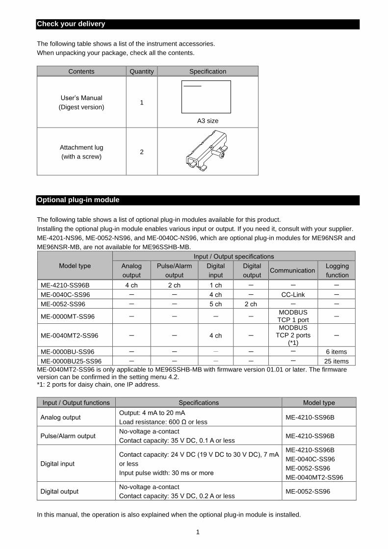
The following table shows a list of the instrument accessories.
When unpacking your package, check all the contents.
Contents Quantity Specification
User’s Manual
(Digest version)
1
A3 size
Attachment lug
(with a screw)
2
Optional plug-in module
The following table shows a list of optional plug-in modules available for this product.
Installing the optional plug-in module enables various input or output. If you need it, consult with your supplier.
ME-4201-NS96, ME-0052-NS96, and ME-0040C-NS96, which are optional plug-in modules for ME96NSR and
ME96NSR-MB, are not available for ME96SSHB-MB.
Model type
Input / Output specifications
Analog
output
Pulse/Alarm
output
Digital
input
Digital
output Communication
Logging
function
ME-4210-SS96B 4 ch 2 ch 1 ch - - -
ME-0040C-SS96 - - 4 ch - CC-Link -
ME-0052-SS96 - - 5 ch 2 ch - -
ME-0000MT-SS96 - - - - MODBUS TCP 1 port
-
ME-0040MT2-SS96 - - 4 ch -
MODBUS TCP 2 ports
(*1) -
ME-0000BU-SS96 - - - - - 6 items
ME-0000BU25-SS96 - - - - - 25 items
ME-0040MT2-SS96 is only applicable to ME96SSHB-MB with firmware version 01.01 or later. The firmware version can be confirmed in the setting menu 4.2. *1: 2 ports for daisy chain, one IP address.
Input / Output functions Specifications Model type
Analog output Output: 4 mA to 20 mA
Load resistance: 600 Ω or less ME-4210-SS96B
Pulse/Alarm output No-voltage a-contact
Contact capacity: 35 V DC, 0.1 A or less ME-4210-SS96B
Digital input
Contact capacity: 24 V DC (19 V DC to 30 V DC), 7 mA
or less
Input pulse width: 30 ms or more
ME-4210-SS96B
ME-0040C-SS96
ME-0052-SS96
ME-0040MT2-SS96
Digital output No-voltage a-contact
Contact capacity: 35 V DC, 0.2 A or less ME-0052-SS96
In this manual, the operation is also explained when the optional plug-in module is installed.
2
Features
The instrument measures load status by wiring the secondary sides of VT (Voltage Transformer) and CT
(Current Transformer) in the power receiving and distribution system and displays various measured values.
The instrument supports highly accurate measurement (accuracy of current/voltage: 0.1%; active energy:
class 0.5S) and high-order harmonic measurement (1st to 31st).
Active energy can be measured by dividing into three time periods such as peak, off-peak, and shoulder.
(Periodic Active Energy)
This instrument enables measurement of active energy/reactive energy/ apparent energy for any period
(interval). (Rolling demand active power/Rolling demand reactive power/Rolling demand apparent power)
The password protection prevents undesired setting change and measured data deletion.
The transmission function (MODBUS RTU communication, CC-Link communication, or MODBUS TCP
commination) transmits measured data to superior monitoring systems.
*CC-Link communication is available when ME-0040C-SS96 (optional plug-in module) is installed.
*MODBUS TCP commination is available when ME-0000MT-SS96 or ME-0040MT2-SS96 (optional plug-in
module) is installed.
The logging function enables to back up measured values in a SD memory card even when a MODBUS RTU
communication error occurs.
*It is available when ME-0000BU-SS96 or ME-0000BU25-SS96 (optional plug-in module) is installed.
This instrument itself can output key measuring elements such as current, voltage, active power, power
factor, and active energy at the power receiving point by installing an optional plug-in module with analog
output/pulse output function. It is ideal for remote monitoring.
*It is available when ME-4210-SS96B (optional plug-in module) is installed
The built-in logging function provides the logging of measured values, alarm logs, and system logs into this
instrument.
The standard complies with the requirements of CE marking, UL standards, KC mark, and FCC/IC.
The support function for checking input wiring enables to determine the wiring condition in the test mode.
When either a voltage input or current input are incorrectly wired, the incorrect wiring part is displayed on the
screen and it also shows a current phase angle, a voltage phase angle, and each value of active power,
voltage, and current.
Trademark
MODBUS is a trademark of Schneider Electric USA Inc.
Other company and product names herein are trademarks or registered trademarks of their respective owners.
In the text, trademark symbols such as ‘TM’ and ‘®’ may not be written.
3
Table of Contents
Check your delivery ................................................................................................................................................ 1
Optional plug-in module .......................................................................................................................................... 1
Features .................................................................................................................................................................. 2
Trademark .............................................................................................................................................................. 2
Table of Contents ................................................................................................................................................... 3
Safety Precautions .................................................................................................................................................. 5
EMC Directive Instruction ....................................................................................................................................... 9
Precautions for KC mark......................................................................................................................................... 9
Table for measuring element code ....................................................................................................................... 10
1. Name and Function of Each Section ............................................................................................................... 11 Name of Each Part ................................................................................................................................ 11 LCD Function ......................................................................................................................................... 14 Function of Operation Buttons ............................................................................................................... 15 LED Display of Optional Plug-in Module ............................................................................................... 17
2. Each Mode Function ........................................................................................................................................ 19
3. How to Set up .................................................................................................................................................. 20 Setting Flow ........................................................................................................................................... 20 Setting Menu 1: Basic Setup (Settings for Phase Wire System, Display Pattern, VT/Direct Voltage,
and CT Primary Current) ....................................................................................................................... 22 Setting Menu 2: Communication Settings (MODBUS RTU Communication Settings) ......................... 26 Setting Menu 2: Communication Settings (CC-Link Communication Settings) .................................... 27 Setting Menu 2: Communication Settings (MODBUS TCP Communication Settings) .......................... 28 Setting Menu 3: Display Settings (Settings for Active/Reactive Energy and Harmonic Measurement) 30 Setting Menu 4: LCD Settings (Settings for Model Display, Version Display, Backlight, and Display
Update Time) ......................................................................................................................................... 32 Setting Menu 5: Pulse/Alarm Settings (Settings for Upper/Lower Limit Alarm, Motor Starting Current
Mask Function, and Pulse Output) ........................................................................................................ 33 Setting Menu 6: Built-in Logging Settings ............................................................................................. 38 Setting Menu 6: Analog Output Settings ............................................................................................... 41 Setting Menu 6: Optional Logging settings............................................................................................ 45 Setting Menu 7: Settings for Periodic Active Energy, Rolling Demand, and Digital Input/Output ......... 47 Setting Menu 8: Special Settings (Settings for Operating Time, IEC Mode, and CO2 equivalent) ........ 49 Setting Menu CL: Present Time Settings .............................................................................................. 51 Setting Confirmation Menu 1 to 9: Confirming the Settings in the Setting Menu 1 to 8 and 9 Test Mode
........................................................................................................................................................... 53 Initialization of Related Items by Changing a Setting ............................................................................ 54 Initialization of All Settings ..................................................................................................................... 55 Settings for Special Display Pattern P00 ............................................................................................... 56 Example for Easy Setup ........................................................................................................................ 58
4. How to Use Test Mode .................................................................................................................................... 60 Test Menu 1: Communication Test ....................................................................................................... 61 Test Menu 2: Alarm Output/Digital Output Test .................................................................................... 62 Test Menu 3: Zero/Span Adjustment for Analog Output ....................................................................... 63 Test Menu 4: Analog Output Test ......................................................................................................... 64 Test Menu 5: Pulse Output Test ............................................................................................................ 65 Test Menu 6: Function for Determining Incorrect Wiring ....................................................................... 66
4.6.1. Incorrect Wiring Patterns Detected by ①Pattern display of incorrect wiring ................................. 69
5. Operation ......................................................................................................................................................... 72 Basic Operation ..................................................................................................................................... 72
5.1.1. How to Switch the Measurement Screen ....................................................................................... 72 5.1.2. How to Switch Phase Display ........................................................................................................ 72 5.1.3. How to Display the Cyclic Mode .................................................................................................... 73 5.1.4. Harmonics Display ......................................................................................................................... 74 5.1.5. Maximum/Minimum Value Display ................................................................................................. 75 5.1.6. How to Display Maximum/Minimum Value .................................................................................... 75 5.1.7. How to Clear Maximum/Minimum Value ........................................................................................ 75 5.1.8. Active Energy/Reactive Energy/Apparent Energy Display ............................................................ 76 5.1.9. How to Change the Display Digit of Active/Reactive/Apparent Energy ......................................... 76 5.1.10. How to Reset Active/Reactive/Apparent Energy to Zero ............................................................... 77 5.1.11. How to Measure Reactive Energy (2 quadrant/4 quadrant measurement) .................................. 77 5.1.12. Each Measuring Item Display during Power Transmission ........................................................... 78
4
Table of Contents
5.1.13. Demand Time Period and Demand Value of Current demand ...................................................... 78 Usage Depending on the Application (Alarm, Periodic Active Energy, Rolling Demand, Operating
Time, Password, etc.) ............................................................................................................................ 79 5.2.1. Upper/Lower Limit Alarm Display and Action ................................................................................ 79 5.2.2. How to Cancel the Upper/Lower Limit Alarm ................................................................................. 81 5.2.3. How to Stop Backlight Blinking Caused by the Upper/Lower Limit Alarm Generation .................. 81 5.2.4. Upper/Lower Limit Alarm Item on the Alarm Contact .................................................................... 81 5.2.5. Periodic Active Energy Display ...................................................................................................... 82 5.2.6. How to Reset Periodic Active Energy to Zero ............................................................................... 82 5.2.7. Rolling Demand Display and Calculation....................................................................................... 83 5.2.8. Rolling Demand Predict Value ....................................................................................................... 84 5.2.9. Rolling Demand Time Period Adjustment ...................................................................................... 84 5.2.10. How to Clear the Rolling Demand Peak Value .............................................................................. 84 5.2.11. Operating Time Display ................................................................................................................. 85 5.2.12. How to Reset Operating Time to Zero ........................................................................................... 85 5.2.13. CO2 Equivalent Display .................................................................................................................. 85 5.2.14. How to Clear the CO2 Equivalent................................................................................................... 85 5.2.15. Digital Input/Output Status Display and Action .............................................................................. 86 5.2.16. How to Cancel the Latch for Digital Input ...................................................................................... 86 5.2.17. How to Prevent Maximum Value Update by Motor Starting Current ............................................. 86 5.2.18. Password Protection Setting .......................................................................................................... 87 5.2.19. Built-in Logging Function ............................................................................................................... 88
6. Others .............................................................................................................................................................. 89 Display Pattern List ................................................................................................................................ 89 Standard Value ...................................................................................................................................... 92 Measuring Items and the Corresponding Display/Output ..................................................................... 96 Instrument Operation ............................................................................................................................. 98 Troubleshooting ..................................................................................................................................... 99
7. Installation ...................................................................................................................................................... 102 Dimensions .......................................................................................................................................... 102 How to Install ....................................................................................................................................... 105
7.2.1. Mounting Hole Dimensions .......................................................................................................... 105 7.2.2. Mounting Position ........................................................................................................................ 105 7.2.3. Mounting and Fixing..................................................................................................................... 105 7.2.4. Optional Plug-in Module Installation ............................................................................................ 105
How to Connect Wiring ........................................................................................................................ 106 7.3.1. Specifications on the Applicable Electrical Wire .......................................................................... 106 7.3.2. Wiring of this Instrument .............................................................................................................. 106 7.3.3. Wiring of the Optional Plug-in Module ......................................................................................... 107 7.3.4. Check the Connection.................................................................................................................. 107
Wiring Diagram .................................................................................................................................... 109 How to insert/remove SD memory card .............................................................................................. 118
8. Specifications................................................................................................................................................. 119 Product Specifications ......................................................................................................................... 119 Compatible Standards ......................................................................................................................... 122 MODBUS RTU Communication Specifications ................................................................................... 122 CC-Link Communication Specifications for optional plug-in module .................................................. 123 MODBUS TCP Communication Specifications for optional plug-in module ....................................... 123 Logging Specifications for optional plug-in module ............................................................................. 124 Input / output specifications (optional plug-in module) ........................................................................ 125 Setting Table (Factory Default Settings and Customer’s Notes Settings) .......................................... 126
9. Appendix ........................................................................................................................................................ 129 ME96SS Calculation Method (3-phase Unbalanced System with Neutral) ........................................ 129 Optional parts ...................................................................................................................................... 130 A List of Examples for Incorrect Wiring Display .................................................................................. 131
9.3.1. 3-phase 4-wire System ................................................................................................................ 131 9.3.2. 3-phase 3-wire System ................................................................................................................ 140 9.3.3. 1-phase 3-wire System ................................................................................................................ 147
5
Safety Precautions
Before use, read these instructions carefully to properly operate the instrument.
Be sure to follow the precautions described here for personnel and product safety.
Keep this manual ready to hand and accessible for future use at all times.
Be sure to forward the manual to the end user.
If you consider using the instrument for a special purpose such as nuclear power plants, aerospace, medical
care, or passenger vehicles, consult with our sales representative.
The instructional icon in the manual is described as follows.
The caution icon ( ) on the main unit indicates that incorrect handling may cause
hazardous conditions. Always follow the subsequent instructions ( ) because
they are important to personal safety. Failure to follow them may result in an
electric shock, a fire, erroneous operation, or damage to the instrument. If the
instrument is used in a manner not specified by the manufacturer, the protection
provided by the instrument may be impaired.
CAUTION
The terminals of auxiliary power (MA, MB) and voltage input (P1, P2, P3, PN) have
hazards of electric shock, explosion, or arc flash. Turn off the power supply of auxiliary
power and input circuit and then handle the instrument.
Precautions on use environment and conditions
Do not use the instrument in the following places:
Failure to follow the instruction may cause a malfunction or reduced product life time.
The ambient temperature exceeds the range -5°C to +55°C.
The average daily temperature exceeds +35°C.
The relative humidity exceeds the range 0 to 85% RH, or condensing.
The altitude exceeds 2000 m.
Pollution Degree: more than 2 *Note 1
Exposed to much dust, corrosive gas, salty environment, or oil mist
Transient over voltage: 4000 V *Note 1
Exposed to excessive vibration or impact
Exposed to rain or water drops
Exposed to direct sunlight
Pieces of metal or inductive substances are scattered.
Exposed to strong magnetic fields or large exogenous noise
Note1: For details about the Pollution Degree and the Transient over voltage category,
refer to EN61010-1:2010.
Grit, dust, and small insects cause poor contact or a failure such as insulation decline that caused by
deposition and moisture absorption. Furthermore, in the area where the air contains conductive dust, a
failure such as a product malfunction or insulation deterioration occurs in a relatively short time. In this
case, you must take measures against it such as putting the instrument in an enclosed board. In
addition, if the temperature inside the board rises, the measures must be undertaken as well.
CAUTION
6
Safety Precautions
Precautions on Installation and wiring
Be sure to read the instructions carefully before installation and wiring.
CAUTION
A qualified electrician must install and wire the instrument for safety.
Supply power to the instrument after completing its assembly work on a cabinet door.
The instrument is to be mounted on the cabinet door. All connections must be kept
inside the cabinet.
The following table shows the specifications on the input/output terminal.
Auxiliary power supply and measuring elements
Auxiliary power supply 100 V AC to 240 V AC (±15%) 50 Hz to 60 Hz
100 V DC to 240 V DC (-30% +15%)
MA, MB
terminals
Measuring
element
Voltage
3-phase 4-wire: max 277/480 V AC
3-phase 3-wire: (DELTA) max 220 V AC
(STAR) max 440 V AC
1-phase 3-wire: max 220/440 V AC
1-phase 2-wire: (DELTA) max 220 V AC
(STAR) max 440 V AC
Category
Ⅲ
P1, P2, P3, PN
terminals
Current 5 A (CT secondary side),
max 30 V AC
Category
Ⅲ
+C1, C1, +C2,
C2, +C3, C3
terminals
Frequency 50 Hz or 60 Hz
The current input terminals must be connected to a CT, external equipment, with basic
insulation.
Be sure to continuously connect the terminals for voltage-measuring purpose and current-
measuring purpose during operation.
Others
MODBUS RTU communication T/R+, T/R-, SG terminals
max 35 V DC
MODBUS TCP communication Ethernet terminal
CC-Link communication DA, DB, DG terminals
Digital input DI1, DI2, DI3, DI4, DI COM, DI+, DI-, DI1+, DI1-, DI2+, DI2-, DI3+, DI3-, DI4+, DI4-, DI5+, DI5- terminals
Digital output DO1+, DO1-, DO2+, DO2- terminals
Analog output CH1+, CH1-, CH2+, CH2-, CH3+, CH3-, CH4+, CH4- terminals
Pulse/Alarm output C1A/A1, C1B/COM1, C2A/A2, C2B/COM2 terminals
Keep the protection sheet affixed to the front of the instrument during installation and
wiring.
Do not drop the instrument from high place. If it is dropped and the display cracks, do
not touch the liquid leaking from the broken LCD or do not get it in your mouth. If you
touched the liquid, rinse it off with soapy water at once.
Do not work under live-line condition. Otherwise, an instrument failure, an electric shock,
or a fire may be caused.
When tapping or wiring, take care not to enter any foreign objects such as chips or wire
pieces into the instrument.
If you pulled the wires with a strong force when connecting them to the terminals, the
terminals might come off. (Tensile load: 39.2 N or less)
Check the wiring diagram carefully. Inappropriate wiring can cause a failure of the
instrument, an electric shock, or a fire.
Use appropriate size wires. The use of an inappropriate size wire can cause a fire due
to heat generation.
Use crimp-type terminals compatible with the wire size. For details, refer to 7.3.1
Specifications on the Applicable Electrical Wire. The use of an inappropriate terminal
can cause a malfunction, failure, or burnout of the instrument or a fire due to damage to
the terminal or poor contact.
Tighten the terminal screws with a specified torque and use a suitable pressure
connector. For details, refer to 7.3.1Specifications on the Applicable Electrical Wire.
Excessive tightening can cause damage to the terminals and screws.
Be sure to confirm the wiring connections strictly after the connection. Poor connection
can cause a malfunction of the instrument, an electric shock, or a fire.
Continued to the next page.
7
Safety Precautions
CAUTION
In order to prevent invasion of noise, MODBUS RTU communication cables, auxiliary
power supply cables, and other signal cables must not be placed close to or bound
together with power lines or high voltage lines. When lying parallel to the power lines or
high voltage lines, refer to the following table for the separation distance. (Except the
input part of the terminal block)
Conditions Distance
Power lines of 600 V AC or less 300 mm or more
Other power lines 600 mm or more
Precautions on preparation before use
Observe the use conditions and environment requirements for installation place.
You must set up the instrument before use. Read the manual carefully to set it up correctly. If the setup is
incorrectly done, the instrument will not be properly operated.
Check the power rating of the instrument and then apply proper voltage.
Precautions on how to use
When operating the instrument, check that active bare wires do not exist around it. If any bare wire existed,
stop the operation immediately and then take appropriate action such as insulation protection.
If a power outage occurred during the setup, the instrument would not be set up correctly. Set it up again
after power recovery.
CAUTION
Do not disassemble or modify the instrument to use. Otherwise, a failure, an electric
shock, or a fire can be caused.
Use the instrument within the rating specified in the manual. If you used it outside the
rating, it might cause not only a malfunction or failure of the instrument but also ignition
or burnout.
Do not open the CT secondary side while the primary current is energized. When the CT
secondary side circuit is open, the primary current flows. However, the secondary
current does not flow. Therefore, a high voltage is generated at the CT secondary side
and the temperature rises, resulting in insulation breakdown in the CT secondary
winding. It may lead to burnout.
When external equipment is connected to the external terminals, the instrument and
external equipment must not be powered and be used after the definitive assembly on
a cabinet door.
The rating of the terminal of external equipment should satisfy that of the external
terminal of the instrument.
Precautions on maintenance
Wipe dirt off the surface with a soft dry cloth.
Do not leave a chemical cloth in contact with the instrument for a long time or do not wipe it with benzene,
thinner, or alcohol.
In order to properly use the instrument for a long time, conduct the following inspections:
(1) Daily maintenance
①No damage in the instrument
②No abnormality with LCD indicator
③No abnormal noise, smell or heat generation
(2) Periodical maintenance
Inspect the following item every six months to once a year.
①No looseness of installation and terminal block connection
CAUTION
Be sure to conduct periodic inspection under the electric outage condition. Failure to follow
the instruction may cause a failure of the instrument, an electric shock, or a fire. Tighten
the terminals regularly to prevent a fire.
8
Safety Precautions
Precautions on storage
To store the instrument, turn off the power supplies of auxiliary power and input circuit, remove the wires
from the terminals, and then put them in a plastic bag.
For long-time storage, avoid the following places. Otherwise, there is danger of an instrument failure or
reduced product life time.
The ambient temperature exceeds the range -25°C to +75°C.
The average daily temperature exceeds +35°C.
The relative humidity exceeds the range 0 to 85% RH, or condensing.
Exposed to much dust, corrosive gas, salty environment, or oil mist.
Exposed to excessive vibration or impact.
Exposed to rain or water drops.
Exposed to direct sunlight.
Pieces of metal or inductive substances are scattered.
Warranty
The warranty period is for one year from the date of your purchase or 18 months after the
manufacturing date, whichever is earlier.
During the warranty period, if any failure occurred in standard use that the product is used in the
condition, method, and environment followed by the conditions and precautions described in the
catalog and user’s manual, we would repair the product without charge.
Even within the warranty period, non-free repair is applied to the following cases.
① Failures caused by the customer’s improper storage, handling, carelessness, or fault.
② Failures caused by faulty workmanship
③ Failures due to faults in use or undue modification
④ Failures due to force majeure such as a fire or abnormal voltage or due to natural disasters such as
earthquakes, windstorms, or floods.
⑤ Failures caused by the problem in question that could not be predicted with the technology available
at the time the product was shipped.
Our company shall not be liable to compensate for any loss arising from events not attributable to our
company, customers’ opportunity loss or lost earnings due to failure of the product, any loss, secondary
loss, or accident caused by a special reason regardless of our company’s predictability, damage to
other products besides our products, or other operations
Replacement cycle of the product
It is recommend that you renew the product every ten years although it depends on your use condition.
The long-term use of the product may cause discoloration of the LCD or a product malfunction.
Disposal
Treat the product properly as industrial waste.
ME-0000BU-SS96 or ME-0000BU25-SS96 (optional plug-in module) is equipped with a lithium
battery. The lithium battery is disposed of according to the local regulation.
In EU member states, there is a separate collection system for waste batteries. Dispose of batteries
properly at the local community waste collection/recycling center.
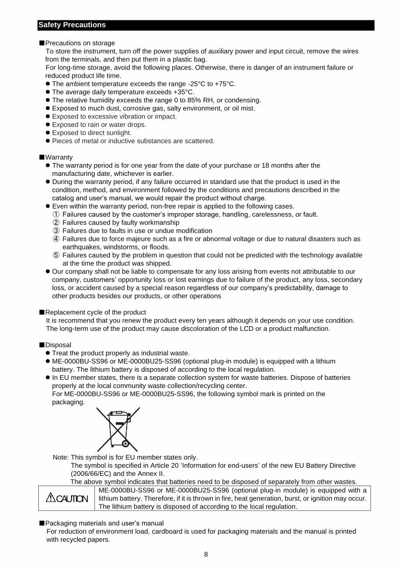
For ME-0000BU-SS96 or ME-0000BU25-SS96, the following symbol mark is printed on the
packaging.
Note: This symbol is for EU member states only.
The symbol is specified in Article 20 ‘Information for end-users’ of the new EU Battery Directive
(2006/66/EC) and the Annex II.
The above symbol indicates that batteries need to be disposed of separately from other wastes.
CAUTION
ME-0000BU-SS96 or ME-0000BU25-SS96 (optional plug-in module) is equipped with a
lithium battery. Therefore, if it is thrown in fire, heat generation, burst, or ignition may occur.
The lithium battery is disposed of according to the local regulation.
Packaging materials and user’s manual
For reduction of environment load, cardboard is used for packaging materials and the manual is printed
with recycled papers.
9
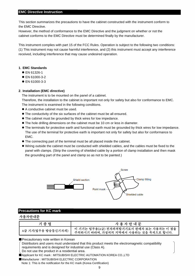
EMC Directive Instruction
This section summarizes the precautions to have the cabinet constructed with the instrument conform to
the EMC Directive.
However, the method of conformance to the EMC Directive and the judgment on whether or not the
cabinet conforms to the EMC Directive must be determined finally by the manufacturer.
This instrument complies with part 15 of the FCC Rules. Operation is subject to the following two conditions:
(1) This instrument may not cause harmful interference, and (2) this instrument must accept any interference
received, including interference that may cause undesired operation.
1.EMC Standards
EN 61326-1
EN 61000-3-2
EN 61000-3-3
2.Installation (EMC directive)
The instrument is to be mounted on the panel of a cabinet.
Therefore, the installation to the cabinet is important not only for safety but also for conformance to EMC.
The instrument is examined in the following conditions.
A conductive cabinet must be used.
The conductivity of the six surfaces of the cabinet must be all ensured.
The cabinet must be grounded by thick wires for low impedance.
The hole drilling dimensions on the cabinet must be 10 cm or less in diameter.
The terminals for protective earth and functional earth must be grounded by thick wires for low impedance.
The use of the terminal for protective earth is important not only for safety but also for conformance to
EMC.
The connecting part of the terminal must be all placed inside the cabinet.
Wiring outside the cabinet must be conducted with shielded cables, and the cables must be fixed to the
panel with clamps. (Strip the covering of shielded cable by a portion of clamp installation and then mask
the grounding part of the panel and clamp so as not to be painted.)
Precautions for KC mark
Precautionary note written in Korean
Distributors and users must understand that this product meets the electromagnetic compatibility requirements and is designed for industrial use (Class A). Do not use the product in a residential area.
Applicant for KC mark : MITSUBISHI ELECTRIC AUTOMATION KOREA CO.,LTD
Manufacturer : MITSUBISHI ELECTRIC CORPORATION
Note 1: This is the notification for the KC mark (Korea Certification)
10
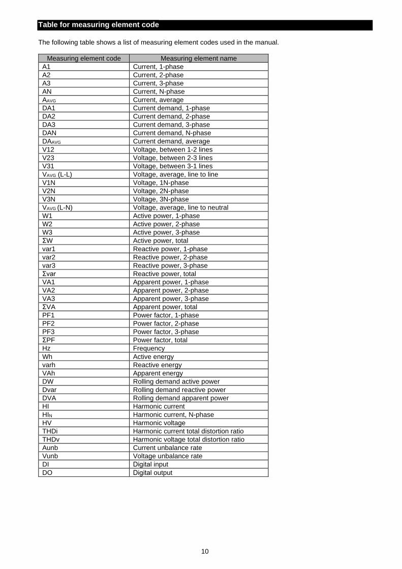
Table for measuring element code
The following table shows a list of measuring element codes used in the manual.
Measuring element code Measuring element name
A1 Current, 1-phase
A2 Current, 2-phase
A3 Current, 3-phase
AN Current, N-phase
AAVG Current, average
DA1 Current demand, 1-phase
DA2 Current demand, 2-phase
DA3 Current demand, 3-phase
DAN Current demand, N-phase
DAAVG Current demand, average
V12 Voltage, between 1-2 lines
V23 Voltage, between 2-3 lines
V31 Voltage, between 3-1 lines
VAVG (L-L) Voltage, average, line to line
V1N Voltage, 1N-phase
V2N Voltage, 2N-phase
V3N Voltage, 3N-phase
VAVG (L-N) Voltage, average, line to neutral
W1 Active power, 1-phase
W2 Active power, 2-phase
W3 Active power, 3-phase
ΣW Active power, total
var1 Reactive power, 1-phase
var2 Reactive power, 2-phase
var3 Reactive power, 3-phase
Σvar Reactive power, total
VA1 Apparent power, 1-phase
VA2 Apparent power, 2-phase
VA3 Apparent power, 3-phase
ΣVA Apparent power, total
PF1 Power factor, 1-phase
PF2 Power factor, 2-phase
PF3 Power factor, 3-phase
ΣPF Power factor, total
Hz Frequency
Wh Active energy
varh Reactive energy
VAh Apparent energy
DW Rolling demand active power
Dvar Rolling demand reactive power
DVA Rolling demand apparent power
HI Harmonic current
HIN Harmonic current, N-phase
HV Harmonic voltage
THDi Harmonic current total distortion ratio
THDv Harmonic voltage total distortion ratio
Aunb Current unbalance rate
Vunb Voltage unbalance rate
DI Digital input
DO Digital output
11
1. Name and Function of Each Section
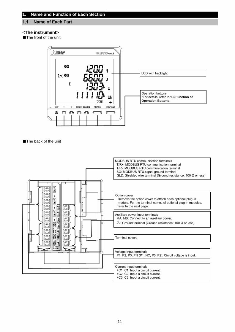
Name of Each Part
<The instrument> The front of the unit
The back of the unit
Operation buttons *For details, refer to 1.3 Function of Operation Buttons.
LCD with backlight
Auxiliary power input terminals MA, MB: Connect to an auxiliary power.
: Ground terminal (Ground resistance: 100 Ω or less)
Current Input terminals +C1, C1: Input a circuit current. +C2, C2: Input a circuit current. +C3, C3: Input a circuit current.
MODBUS RTU communication terminals T/R+: MODBUS RTU communication terminal T/R-: MODBUS RTU communication terminal SG: MODBUS RTU signal ground terminal SLD: Shielded wire terminal (Ground resistance: 100 Ω or less)
Option cover Remove the option cover to attach each optional plug-in module. For the terminal names of optional plug-in modules, refer to the next page.
Voltage Input terminals P1, P2, P3, PN (P1, NC, P3, P2): Circuit voltage is input.
Terminal covers
12
1. Name and Function of Each Section
1.1. Name of Each Part
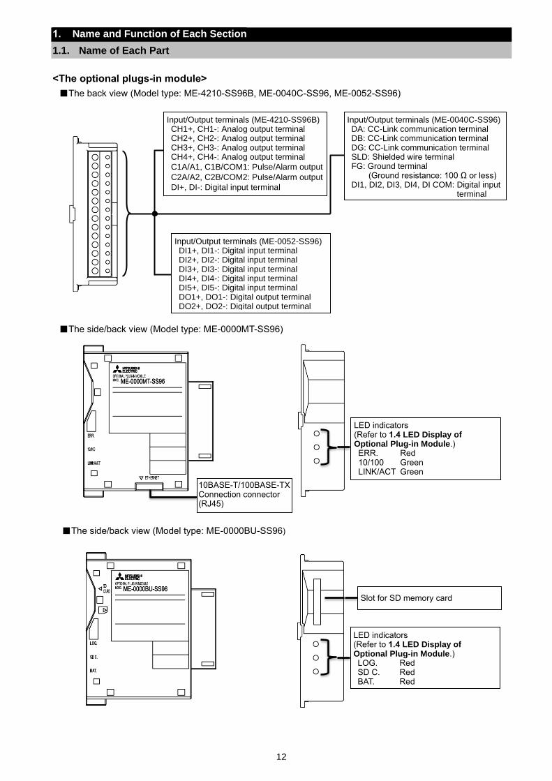
<The optional plugs-in module>
The back view (Model type: ME-4210-SS96B, ME-0040C-SS96, ME-0052-SS96)
The side/back view (Model type: ME-0000MT-SS96)
The side/back view (Model type: ME-0000BU-SS96)
Input/Output terminals (ME-4210-SS96B) CH1+, CH1-: Analog output terminal CH2+, CH2-: Analog output terminal CH3+, CH3-: Analog output terminal CH4+, CH4-: Analog output terminal
C1A/A1, C1B/COM1: Pulse/Alarm output
C2A/A2, C2B/COM2: Pulse/Alarm output
DI+, DI-: Digital input terminal
Input/Output terminals (ME-0040C-SS96) DA: CC-Link communication terminal DB: CC-Link communication terminal DG: CC-Link communication terminal SLD: Shielded wire terminal FG: Ground terminal
(Ground resistance: 100 Ω or less) DI1, DI2, DI3, DI4, DI COM: Digital input
terminal
Input/Output terminals (ME-0052-SS96) DI1+, DI1-: Digital input terminal DI2+, DI2-: Digital input terminal DI3+, DI3-: Digital input terminal DI4+, DI4-: Digital input terminal DI5+, DI5-: Digital input terminal DO1+, DO1-: Digital output terminal DO2+, DO2-: Digital output terminal
10BASE-T/100BASE-TX Connection connector (RJ45)
LED indicators (Refer to 1.4 LED Display of Optional Plug-in Module.) ERR. Red 10/100 Green LINK/ACT Green
LED indicators (Refer to 1.4 LED Display of Optional Plug-in Module.) LOG. Red SD C. Red BAT. Red
Slot for SD memory card
13
1. Name and Function of Each Section
1.1. Name of Each Part
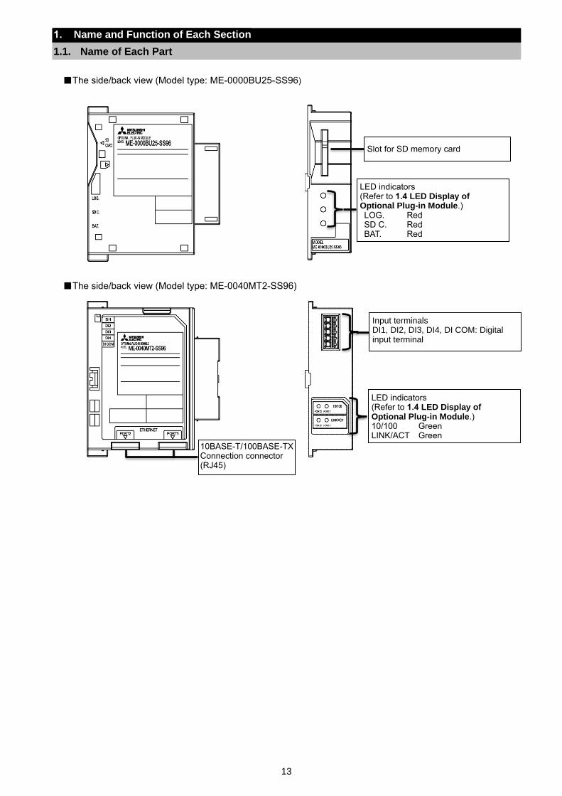
The side/back view (Model type: ME-0000BU25-SS96)
The side/back view (Model type: ME-0040MT2-SS96)
LED indicators (Refer to 1.4 LED Display of Optional Plug-in Module.) LOG. Red SD C. Red BAT. Red
Slot for SD memory card
10BASE-T/100BASE-TX Connection connector (RJ45)
LED indicators (Refer to 1.4 LED Display of Optional Plug-in Module.) 10/100 Green LINK/ACT Green
Input terminals DI1, DI2, DI3, DI4, DI COM: Digital input terminal
14
1. Name and Function of Each Section
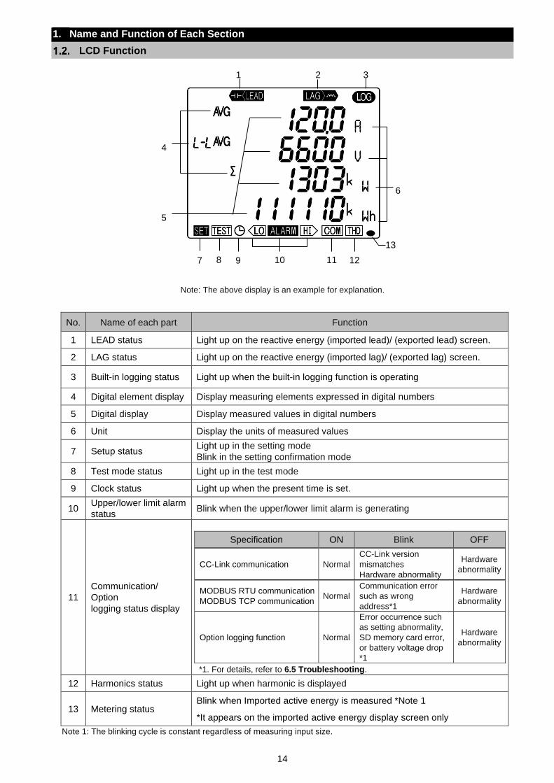
LCD Function
Note: The above display is an example for explanation.
No. Name of each part Function
1 LEAD status Light up on the reactive energy (imported lead)/ (exported lead) screen.
2 LAG status Light up on the reactive energy (imported lag)/ (exported lag) screen.
3 Built-in logging status Light up when the built-in logging function is operating
4 Digital element display Display measuring elements expressed in digital numbers
5 Digital display Display measured values in digital numbers
6 Unit Display the units of measured values
7 Setup status Light up in the setting mode
Blink in the setting confirmation mode
8 Test mode status Light up in the test mode
9 Clock status Light up when the present time is set.
10 Upper/lower limit alarm
status Blink when the upper/lower limit alarm is generating
11
Communication/
Option
logging status display
Specification ON Blink OFF
CC-Link communication Normal
CC-Link version
mismatches
Hardware abnormality
Hardware
abnormality
MODBUS RTU communication
MODBUS TCP communication Normal
Communication error
such as wrong
address*1
Hardware
abnormality
Option logging function Normal
Error occurrence such
as setting abnormality,
SD memory card error,
or battery voltage drop
*1
Hardware
abnormality
*1. For details, refer to 6.5 Troubleshooting.
12 Harmonics status Light up when harmonic is displayed
13 Metering status Blink when Imported active energy is measured *Note 1
*It appears on the imported active energy display screen only
Note 1: The blinking cycle is constant regardless of measuring input size.
6
1 2
4
13
11 12 9 8 7 10
5
3
15
1. Name and Function of Each Section
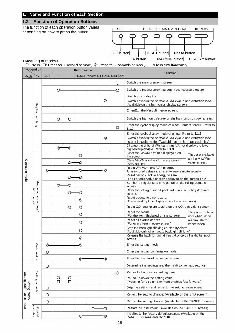
Function of Operation Buttons
The function of each operation button varies depending on how to press the button.
<Meaning of marks> : Press, : Press for 1 second or more, : Press for 2 seconds or more, ―― : Press simultaneously
Operation
Mode
Button name Function
SET - + RESET MAX/MIN PHASE DISPLAY
Opera
ting m
ode
Dis
pla
y s
witc
hin
g
Switch the measurement screen.
Switch the measurement screen in the reverse direction.
Switch phase display.
Switch between the harmonic RMS value and distortion ratio. (Available on the harmonics display screen)
Enter/Exit the Max/Min value screen.
Switch the harmonic degree on the harmonics display screen.
Enter the cyclic display mode of measurement screen. Refer to 5.1.3.
Enter the cyclic display mode of phase. Refer to 5.1.3.
Switch between the harmonic RMS value and distortion ratio screen in cyclic mode. (Available on the harmonics display)
Change the units of Wh, varh, and VAh or display the lower-digit enlarged view. Refer to 5.1.9.
Me
asure
d v
alu
e c
lear/
Ala
rm re
set
Clear the Max/Min values displayed on the screen.
They are available
on the Max/Min
value screen. Clear Max/Min values for every item in every screen.
Reset Wh, varh, and VAh to zero. All measured values are reset to zero simultaneously.
Reset periodic active energy to zero. (The periodic active energy displayed on the screen only)
Set the rolling demand time period on the rolling demand screen.
Clear the rolling demand peak value on the rolling demand screen.
Reset operating time to zero. (The operating time displayed on the screen only)
Reset CO2 equivalent to zero on the CO2 equivalent screen.
Reset the alarm. (For the item displayed on the screen)
They are available
only when set to
manual alarm
cancellation. Reset all alarms at once. (For every item in every screen)
Stop the backlight blinking caused by alarm. (Available only when set to backlight blinking)
Release the latch for digital input at once on the digital input screen.
Mo
de s
witc
h
Enter the setting mode.
Enter the setting confirmation mode.
Enter the password protection screen.
Settin
g m
ode/
Settin
g c
onfirm
atio
n m
ode
Settin
g o
pera
tion
Determine the settings and then shift to the next settings.
Return to the previous setting item.
Round up/down the setting value. (Pressing for 1 second or more enables fast forward.)
Skip the settings and return to the setting menu screen.
Reflect the setting change. (Available on the END screen)
Cancel the setting change. (Available on the CANCEL screen)
Specia
l
opera
tion
Restart the instrument. (Available on the CANCEL screen)
Initialize to the factory default settings. (Available on the CANCEL screen) Refer to 3.16.
SET - + RESET MAX/MIN PHASE DISPLAY
SET button RESET button Phase button
+/- button MAX/MIN button DISPLAY button

16
1. Name and Function of Each Section
1.3. Function of Operation Buttons
Note: During backlight off mode, pressing any operation button first turns on the backlight. In addition, pressing any button
again enables the use of the functions in the above table.
CAUTION
When you execute a function such as ‘Reset Max/Min value’ or ‘Reset Wh, varh, and
VAh to zero’, past data is deleted. If you need to keep the data, record the data before
the reset operation.
When you execute ‘Restart the instrument’, the entire measurement function
(measurement display, communication) will stop for a few seconds.
17
1. Name and Function of Each Section
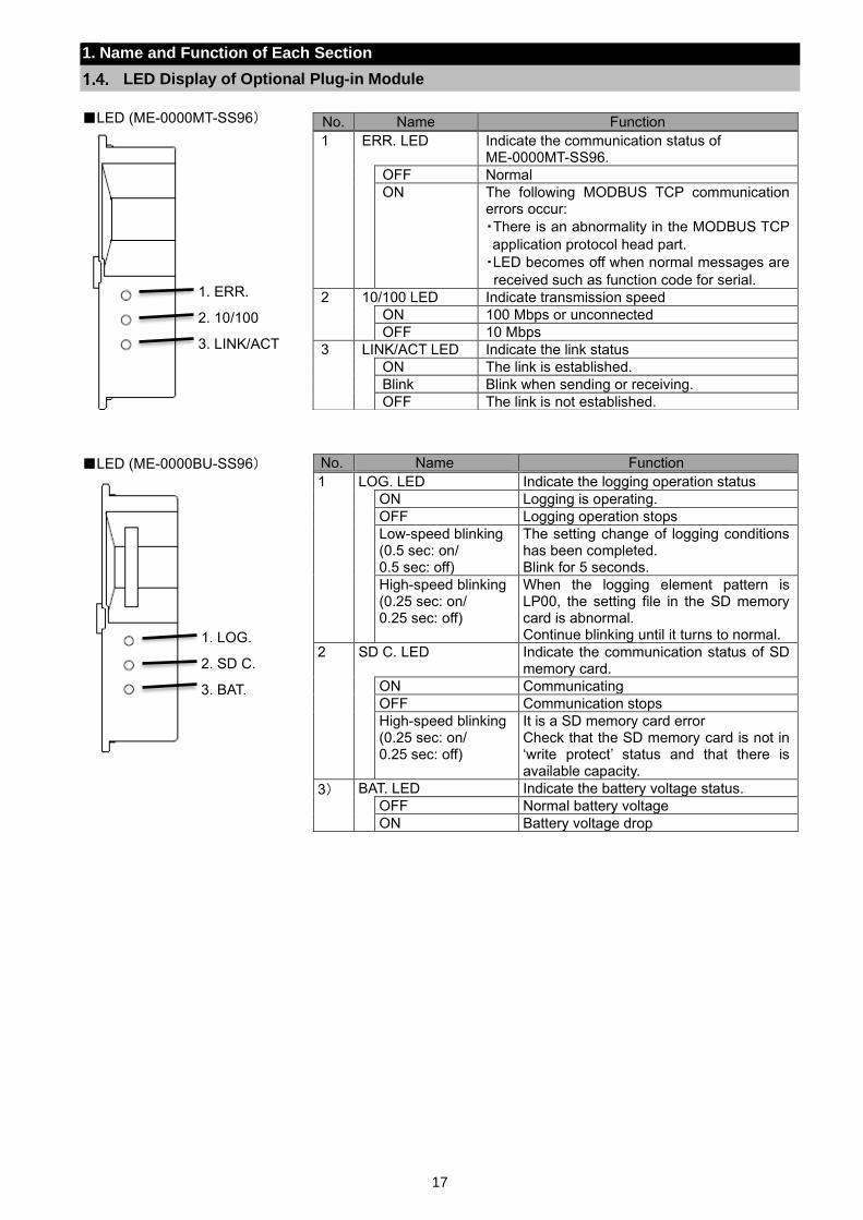
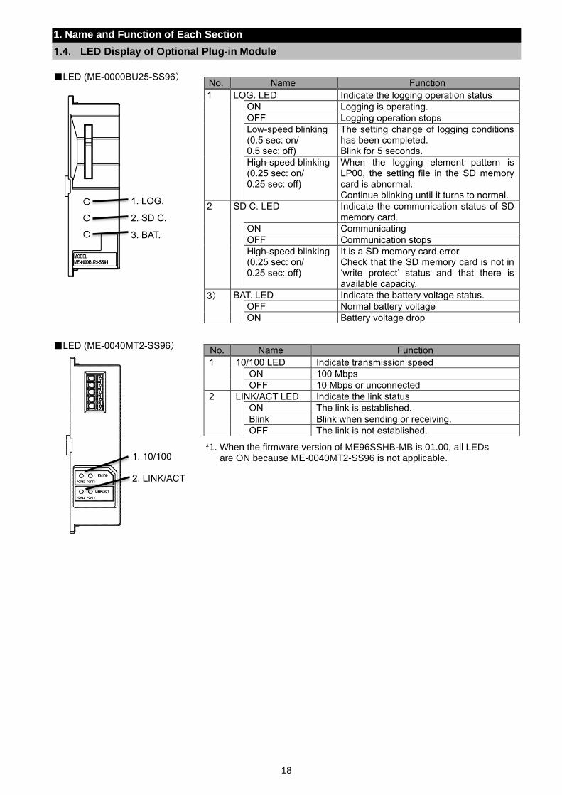
LED Display of Optional Plug-in Module
LED (ME-0000MT-SS96)
LED (ME-0000BU-SS96)
No. Name Function
1 ERR. LED Indicate the communication status of ME-0000MT-SS96.
OFF Normal
ON The following MODBUS TCP communication errors occur:
・There is an abnormality in the MODBUS TCP
application protocol head part.
・LED becomes off when normal messages are
received such as function code for serial.
2 10/100 LED Indicate transmission speed
ON 100 Mbps or unconnected
OFF 10 Mbps
3 LINK/ACT LED Indicate the link status
ON The link is established.
Blink Blink when sending or receiving.
OFF The link is not established.
No. Name Function
1 LOG. LED Indicate the logging operation status
ON Logging is operating.
OFF Logging operation stops
Low-speed blinking (0.5 sec: on/ 0.5 sec: off)
The setting change of logging conditions has been completed. Blink for 5 seconds.
High-speed blinking (0.25 sec: on/ 0.25 sec: off)
When the logging element pattern is LP00, the setting file in the SD memory card is abnormal. Continue blinking until it turns to normal.
2 SD C. LED Indicate the communication status of SD memory card.
ON Communicating
OFF Communication stops
High-speed blinking (0.25 sec: on/ 0.25 sec: off)
It is a SD memory card error Check that the SD memory card is not in ‘write protect’ status and that there is available capacity.
3) BAT. LED Indicate the battery voltage status.
OFF Normal battery voltage
ON Battery voltage drop
1. ERR.
2. 10/100
3. LINK/ACT
1. LOG.
2. SD C.
3. BAT.
18
1. Name and Function of Each Section
LED Display of Optional Plug-in Module
LED (ME-0000BU25-SS96)
LED (ME-0040MT2-SS96)
No. Name Function
1 LOG. LED Indicate the logging operation status
ON Logging is operating.
OFF Logging operation stops
Low-speed blinking (0.5 sec: on/ 0.5 sec: off)
The setting change of logging conditions has been completed. Blink for 5 seconds.
High-speed blinking (0.25 sec: on/ 0.25 sec: off)
When the logging element pattern is LP00, the setting file in the SD memory card is abnormal. Continue blinking until it turns to normal.
2 SD C. LED Indicate the communication status of SD memory card.
ON Communicating
OFF Communication stops
High-speed blinking (0.25 sec: on/ 0.25 sec: off)
It is a SD memory card error Check that the SD memory card is not in ‘write protect’ status and that there is available capacity.
3) BAT. LED Indicate the battery voltage status.
OFF Normal battery voltage
ON Battery voltage drop
No. Name Function
1 10/100 LED Indicate transmission speed
ON 100 Mbps
OFF 10 Mbps or unconnected
2 LINK/ACT LED Indicate the link status
ON The link is established.
Blink Blink when sending or receiving.
OFF The link is not established.
1. LOG.
2. SD C.
3. BAT.
1. 10/100 2. LINK/ACT
*1. When the firmware version of ME96SSHB-MB is 01.00, all LEDs are ON because ME-0040MT2-SS96 is not applicable.
19
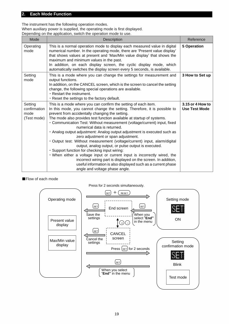
2. Each Mode Function
The instrument has the following operation modes.
When auxiliary power is supplied, the operating mode is first displayed.
Depending on the application, switch the operation mode to use.
Mode Description Reference
Operating
mode
This is a normal operation mode to display each measured value in digital
numerical number. In the operating mode, there are ‘Present value display’
that shows values at present and ‘Max/Min value display’ that shows the
maximum and minimum values in the past.
In addition, on each display screen, the cyclic display mode, which
automatically switches the display screen every 5 seconds, is available.
5 Operation
Setting
mode
This is a mode where you can change the settings for measurement and
output functions.
In addition, on the CANCEL screen, which is the screen to cancel the setting
change, the following special operations are available.
・ Restart the instrument.
・ Reset the settings to the factory default.
3 How to Set up
Setting
confirmation
mode
(Test mode)
This is a mode where you can confirm the setting of each item.
In this mode, you cannot change the setting. Therefore, it is possible to
prevent from accidentally changing the setting.
The mode also provides test function available at startup of systems.
・ Communication Test: Without measurement (voltage/current) input, fixed
numerical data is returned.
・ Analog output adjustment: Analog output adjustment is executed such as
zero adjustment or span adjustment.
・ Output test: Without measurement (voltage/current) input, alarm/digital
output, analog output, or pulse output is executed.
・ Support function for checking input wiring:
・ When either a voltage input or current input is incorrectly wired, the
incorrect wiring part is displayed on the screen. In addition,
useful information is also displayed such as a current phase
angle and voltage phase angle.
3.15 or 4 How to
Use Test Mode
Flow of each mode
SET
+ -
Operating mode
Present value display
Max/Min value display
Setting mode
Setting confirmation mode
Test mode
SET
SET SET
SET
SET RESET
End screen
CANCEL screen
+
Save the settings
Cancel the settings
Press for 2 seconds simultaneously.
When you select “End” in the menu
When you select “End” in the menu
Press for 2 seconds
ON
Blink
20
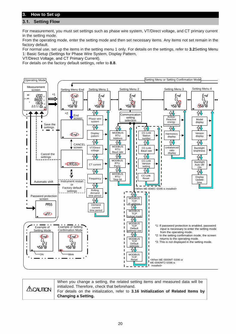
3. How to Set up
Setting Flow
For measurement, you must set settings such as phase wire system, VT/Direct voltage, and CT primary current in the setting mode. From the operating mode, enter the setting mode and then set necessary items. Any items not set remain in the factory default. For normal use, set up the items in the setting menu 1 only. For details on the settings, refer to 3.2Setting Menu 1: Basic Setup (Settings for Phase Wire System, Display Pattern, VT/Direct Voltage, and CT Primary Current). For details on the factory default settings, refer to 8.8.
CAUTION
When you change a setting, the related setting items and measured data will be
initialized. Therefore, check that beforehand.
For details on the initialization, refer to 3.16 Initialization of Related Items by
Changing a Setting.
Measurement screen
Setting Menu End
End screen
CANCEL screen
Automatic shift
Cancel the settings
Save the settings
Instrument restart or
Factory default settings
Operating Mode
*2
*1
Password protection screen
Harmonics display
Active/
Reactive energy
measurement
Frequency
Setting Menu 1
Setting Menu 2
Setting Menu 3
<When ME-0040C-SS96 is installed>
Communication setting
selection Model display
Version display
Backlight brightness
Backlight Auto off/
ON
Display Update
time
Setting Menu 4
Menu 3
Menu 3
*1: If password protection is enabled, password input is necessary to enter the setting mode from the operating mode.
*2: In the setting confirmation mode, the screen returns to the operating mode.
*3: This is not displayed in the setting mode.
Setting Menu or Setting Confirmation Mode
MODBUS TCP
IP address
MODBUS TCP
Subnet mask
MODBUS TCP
Default gateway use
MODBUS TCP
Default gateway
MODBUS TCP
Reset
<When ME-0000MT-SS96 or ME-0040MT2-SS96 is installed>
Unbalanced ratio
display
Example of Setting Mode
Example of Setting Confirmation Mode
ON Blink
CT current
VT/Direct voltage
Display pattern
Phase wire system
MODBUS RTU
Address
MODBUS RTU Parity
MODBUS RTU
Stop bit
MODBUS
RTU Baud rate
CC-Link Station number
CC-Link Baud rate
CC-Link Version setting
CC-Link Reset
Rolling demand
time period
Demand current
time period
21
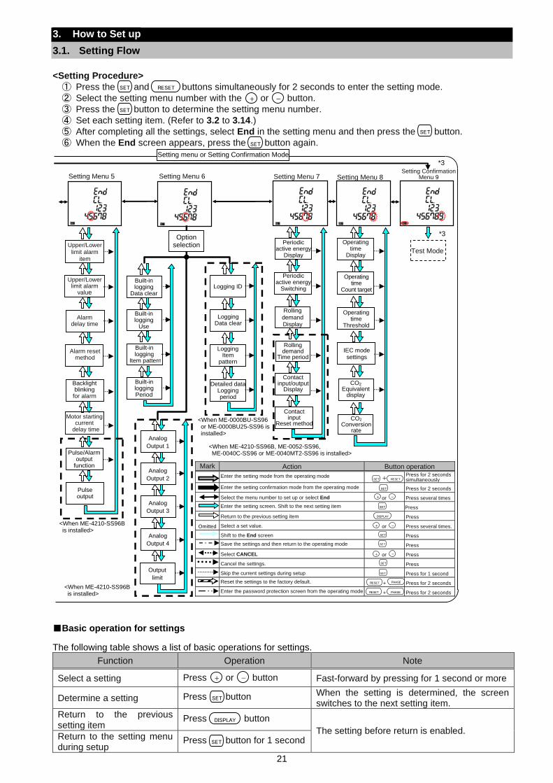
3. How to Set up
3.1. Setting Flow
<Setting Procedure>
① Press the and buttons simultaneously for 2 seconds to enter the setting mode.
② Select the setting menu number with the or button.
③ Press the button to determine the setting menu number.
④ Set each setting item. (Refer to 3.2 to 3.14.)
⑤ After completing all the settings, select End in the setting menu and then press the button.
⑥ When the End screen appears, press the button again.
Analog
Output 4
Analog
Output 3
Analog
Output 2
Analog
Output 1
Contact input
Reset method
Contact input/output
Display
Rolling demand
Time period
Rolling demand Display
Periodic active energy
Display
CO2 Conversion
rate
CO2 Equivalent
display
Setting Confirmation Menu 9
Setting Menu 5
Setting Menu 6
Setting Menu 7
Setting Menu 8
Pulse output
*3
*3
<When ME-4210-SS96B is installed>
<When ME-4210-SS96B, ME-0052-SS96, ME-0040C-SS96 or ME-0040MT2-SS96 is installed>
Setting menu or Setting Confirmation Mode
Detailed data
Logging period
Logging
Item pattern
Logging Data clear
Logging ID
Option selection
Mark Action Button operation
Enter the setting mode from the operating mode + Press for 2 seconds simultaneously
Enter the setting confirmation mode from the operating mode Press for 2 seconds
Select the menu number to set up or select End or Press several times
Enter the setting screen. Shift to the next setting item Press
Return to the previous setting item Press
Omitted Select a set value. or Press several times.
Shift to the End screen Press
Save the settings and then return to the operating mode Press
Select CANCEL or Press
Cancel the settings. Press
Skip the current settings during setup Press for 1 second
Reset the settings to the factory default. + Press for 2 seconds
Enter the password protection screen from the operating mode + Press for 2 seconds
Built-in logging Period
Built-in logging
Item pattern
Built-in logging
Use
Built-in logging
Data clear
DISPLAY
RESET
+ -
SET
PHASERESET
SET
SET
SET
SET
+ -
SET
SET
PHASERESET
+ -
Upper/Lower limit alarm
value
Alarm delay time
Alarm reset method
Backlight blinking for alarm
Motor starting current
delay time
Upper/Lower limit alarm
item
Pulse/Alarm output
function
Test Mode
Operating time
Threshold
Operating time
Count target
Operating time
Display
IEC mode settings
<When ME-0000BU-SS96 or ME-0000BU25-SS96 is installed>
Output
limit
Periodic
active energy Switching
<When ME-4210-SS96B is installed>
Basic operation for settings
The following table shows a list of basic operations for settings.
Function Operation Note
Select a setting Press or button Fast-forward by pressing for 1 second or more
Determine a setting Press button When the setting is determined, the screen switches to the next setting item.
Return to the previous setting item
Press button
The setting before return is enabled. Return to the setting menu during setup
Press button for 1 second
SET
+ -
SET
SET
RESET
+ -
SET
SET
DISPLAY
SET
22
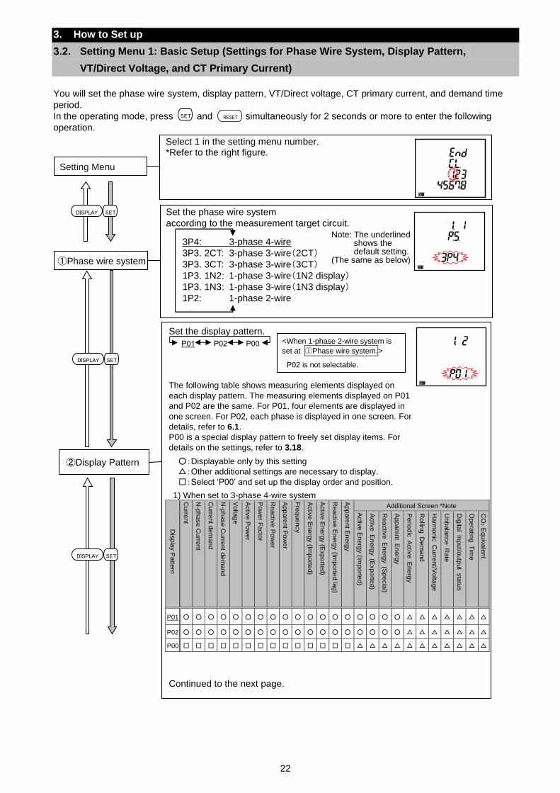
Set the phase wire system
according to the measurement target circuit.
①Phase wire system
3P4: 3-phase 4-wire
3P3. 2CT: 3-phase 3-wire(2CT)
3P3. 3CT: 3-phase 3-wire(3CT)
1P3. 1N2: 1-phase 3-wire(1N2 display)
1P3. 1N3: 1-phase 3-wire(1N3 display)
1P2: 1-phase 2-wire
Note: The underlined shows the default setting.
(The same as below)
3. How to Set up
Setting Menu 1: Basic Setup (Settings for Phase Wire System, Display Pattern,
VT/Direct Voltage, and CT Primary Current)
You will set the phase wire system, display pattern, VT/Direct voltage, CT primary current, and demand time
period.
In the operating mode, press and simultaneously for 2 seconds or more to enter the following
operation.
SET RESET
SETDISPLAY
Set the display pattern. The following table shows measuring elements displayed on
each display pattern. The measuring elements displayed on P01
and P02 are the same. For P01, four elements are displayed in
one screen. For P02, each phase is displayed in one screen. For
details, refer to 6.1.
P00 is a special display pattern to freely set display items. For
details on the settings, refer to 3.18.
:Displayable only by this setting
:Other additional settings are necessary to display.
:Select ‘P00’ and set up the display order and position.
1) When set to 3-phase 4-wire system
Dis
pla
y P
atte
rn
Curre
nt
N-p
hase C
urre
nt
Curre
nt d
em
an
d
N-p
hase C
urre
nt d
em
and
Volta
ge
Activ
e P
ow
er
Pow
er F
acto
r
Reactiv
e P
ow
er
Appa
rent P
ow
er
Fre
qu
ency
Activ
e E
nerg
y (Im
po
rted)
Activ
e E
nerg
y (E
xp
orte
d)
Reactiv
e E
nerg
y (Im
po
rted la
g)
Appa
rent E
nerg
y
Additional Screen *Note
Activ
e E
nerg
y (Im
po
rted)
Activ
e E
nerg
y (E
xpo
rted)
Reactiv
e E
nerg
y (S
pe
cia
l)
Appa
rent
En
erg
y
Perio
dic
A
ctiv
e E
nerg
y
Rollin
g D
em
and
Harm
onic
C
urre
nt/V
olta
ge
Unbala
nce R
ate
Dig
ital
Inp
ut/o
utp
ut
sta
tus
Ope
ratin
g T
ime
CO
2 E
quiv
ale
nt
P01
P02
P00
Continued to the next page.
②Display Pattern
Select 1 in the setting menu number. *Refer to the right figure.
Setting Menu
<When 1-phase 2-wire system is
set at ①Phase wire system.>
P02 is not selectable.
P01 P02 P00
SETDISPLAY
SETDISPLAY
23
3. How to Set up
3.2 Setting Menu 1: Basic Setup (Settings for Phase Wire System, Display Pattern,
VT/Direct Voltage, and CT Primary Current)
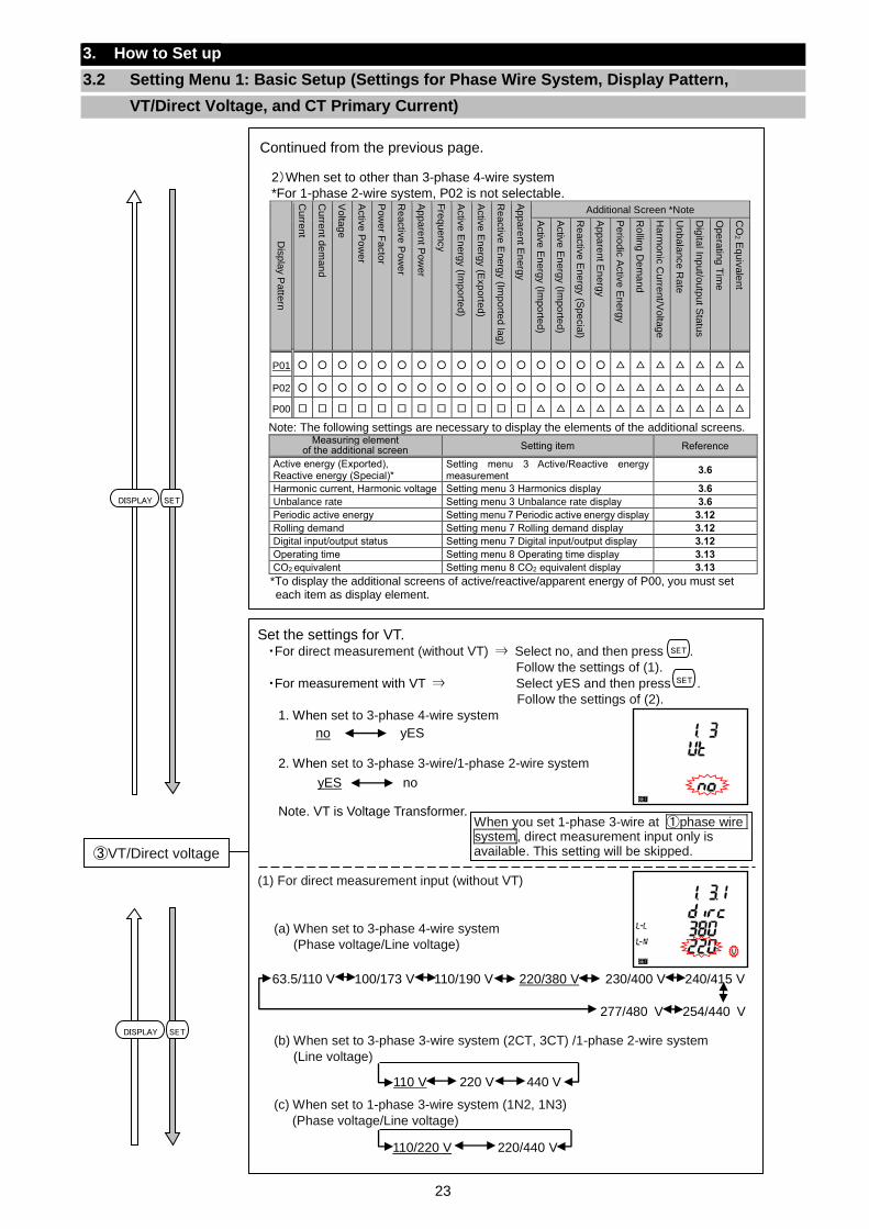
SETDISPLAY
Set the settings for VT. ・For direct measurement (without VT) ⇒ Select no, and then press .
Follow the settings of (1).
・For measurement with VT ⇒ Select yES and then press .
Follow the settings of (2).
1. When set to 3-phase 4-wire system
2. When set to 3-phase 3-wire/1-phase 2-wire system
Note. VT is Voltage Transformer.
(1) For direct measurement input (without VT)
(a) When set to 3-phase 4-wire system
(Phase voltage/Line voltage)
(b) When set to 3-phase 3-wire system (2CT, 3CT) /1-phase 2-wire system
(Line voltage)
(c) When set to 1-phase 3-wire system (1N2, 1N3)
(Phase voltage/Line voltage)
(b) For the settings of 3-phase 3-wire (2CT, 3CT) or 1-phase 2-wire (Line voltage)
(c) For the settings of 1-phase 3-wire(1N2, 1N3) (Phase voltage/Line voltage)
③VT/Direct voltage
When you set 1-phase 3-wire at ①phase wire system, direct measurement input only is available. This setting will be skipped.
SET
SET
110 V 220 V 440 V
yES no
110/220 V 220/440 V
no yES
63.5/110 V 100/173 V 110/190 V 220/380 V 230/400 V 240/415 V
277/480 V 254/440 V
SETDISPLAY
Continued from the previous page.
2)When set to other than 3-phase 4-wire system
*For 1-phase 2-wire system, P02 is not selectable.
Dis
pla
y P
atte
rn
Curre
nt
Curre
nt d
em
an
d
Volta
ge
Activ
e P
ow
er
Pow
er F
acto
r
Reactiv
e P
ow
er
Appa
rent P
ow
er
Fre
qu
ency
Activ
e E
nerg
y (Im
po
rted)
Activ
e E
nerg
y (E
xp
orte
d)
Reactiv
e E
nerg
y (Im
po
rted la
g)
Appa
rent E
nerg
y
Additional Screen *Note
Activ
e E
nerg
y (Im
po
rted)
Activ
e E
nerg
y (Im
po
rted)
Reactiv
e E
nerg
y (S
pe
cia
l)
Appa
rent E
nerg
y
Perio
dic
Activ
e E
nerg
y
Rollin
g D
em
and
Harm
onic
Cu
rrent/V
olta
ge
Unbala
nce R
ate
Dig
ital In
put/o
utp
ut S
tatu
s
Ope
ratin
g T
ime
CO
2 Equiv
ale
nt
P01
P02
P00
Note: The following settings are necessary to display the elements of the additional screens. Measuring element
of the additional screen Setting item Reference
Active energy (Exported), Reactive energy (Special)*
Setting menu 3 Active/Reactive energy measurement
3.6
Harmonic current, Harmonic voltage Setting menu 3 Harmonics display 3.6
Unbalance rate Setting menu 3 Unbalance rate display 3.6
Periodic active energy Setting menu 7 Periodic active energy display 3.12
Rolling demand Setting menu 7 Rolling demand display 3.12
Digital input/output status Setting menu 7 Digital input/output display 3.12
Operating time Setting menu 8 Operating time display 3.13
CO2 equivalent Setting menu 8 CO2 equivalent display 3.13
*To display the additional screens of active/reactive/apparent energy of P00, you must set each item as display element.
24
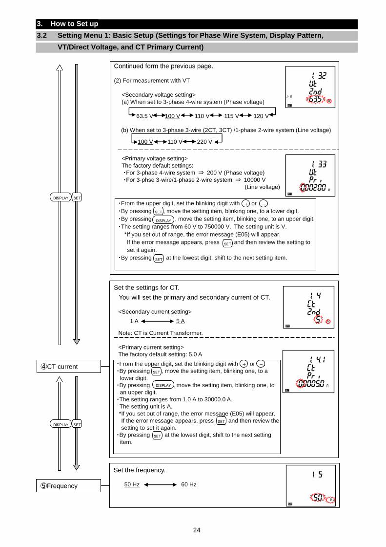
Set the settings for CT.
You will set the primary and secondary current of CT.
<Secondary current setting>
Note: CT is Current Transformer.
<Primary current setting> The factory default setting: 5.0 A
④CT current ・From the upper digit, set the blinking digit with or .
・By pressing , move the setting item, blinking one, to a
lower digit.
・By pressing , move the setting item, blinking one, to
an upper digit.
・The setting ranges from 1.0 A to 30000.0 A.
The setting unit is A.
*If you set out of range, the error message (E05) will appear.
If the error message appears, press and then review the
setting to set it again.
・By pressing at the lowest digit, shift to the next setting
item.
1 A 5 A
+ -
DISPLAY
SET
SET
SET
3. How to Set up
3.2 Setting Menu 1: Basic Setup (Settings for Phase Wire System, Display Pattern,
VT/Direct Voltage, and CT Primary Current)
Continued form the previous page.
(2) For measurement with VT
<Secondary voltage setting>
(a) When set to 3-phase 4-wire system (Phase voltage)
63.5 V 100 V 110 V 115 V 120 V
(b) When set to 3-phase 3-wire (2CT, 3CT) /1-phase 2-wire system (Line voltage)
<Primary voltage setting>
The factory default settings:
・For 3-phase 4-wire system ⇒ 200 V (Phase voltage)
・For 3-phse 3-wire/1-phase 2-wire system ⇒ 10000 V
(Line voltage)
・From the upper digit, set the blinking digit with or .
・By pressing , move the setting item, blinking one, to a lower digit.
・By pressing , move the setting item, blinking one, to an upper digit.
・The setting ranges from 60 V to 750000 V. The setting unit is V.
*If you set out of range, the error message (E05) will appear.
If the error message appears, press and then review the setting to
set it again.
・By pressing at the lowest digit, shift to the next setting item.
100 V 110 V 220 V
+ -
SET
DISPLAY
SET
SET
Set the frequency.
⑤Frequency 50 Hz 60 Hz
SETDISPLAY
SETDISPLAY
25
3. How to Set up
3.2 Setting Menu 1: Basic Setup (Settings for Phase Wire System, Display Pattern,
VT/Direct Voltage, and CT Primary Current)
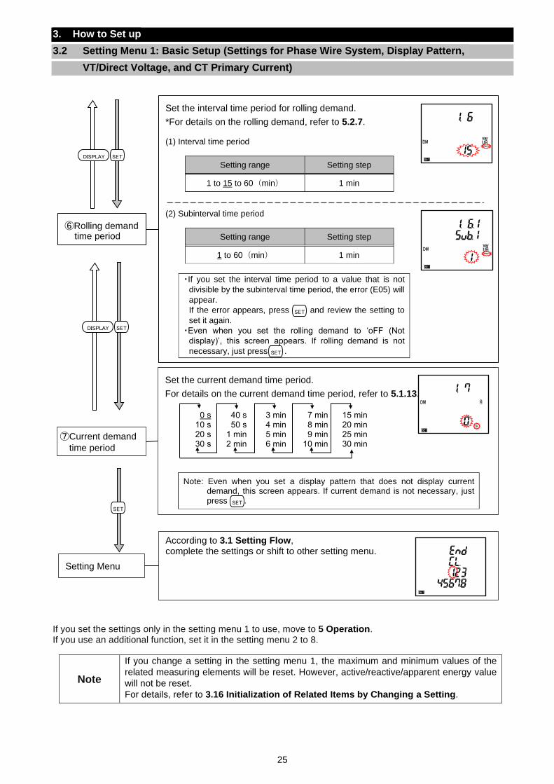
If you set the settings only in the setting menu 1 to use, move to 5 Operation. If you use an additional function, set it in the setting menu 2 to 8.
Note
If you change a setting in the setting menu 1, the maximum and minimum values of the
related measuring elements will be reset. However, active/reactive/apparent energy value
will not be reset.
For details, refer to 3.16 Initialization of Related Items by Changing a Setting.
Set the interval time period for rolling demand.
*For details on the rolling demand, refer to 5.2.7. (1) Interval time period
Setting range Setting step
1 to 15 to 60(min) 1 min
(2) Subinterval time period
Setting range Setting step
1 to 60(min) 1 min
・If you set the interval time period to a value that is not
divisible by the subinterval time period, the error (E05) will
appear.
If the error appears, press and review the setting to
set it again.
・Even when you set the rolling demand to ‘oFF (Not
display)’, this screen appears. If rolling demand is not
necessary, just press .
⑥Rolling demand time period
SET
Set the current demand time period.
For details on the current demand time period, refer to 5.1.13.
Note: Even when you set a display pattern that does not display current demand, this screen appears. If current demand is not necessary, just press .
⑦Current demand
time period
SET
0 s 10 s 20 s 30 s
40 s 50 s
1 min 2 min
3 min 4 min 5 min 6 min
7 min 8 min 9 min
10 min
15 min 20 min 25 min 30 min
According to 3.1 Setting Flow, complete the settings or shift to other setting menu.
Setting Menu
SETDISPLAY
SET
SET
SETDISPLAY
26
3. How to Set up
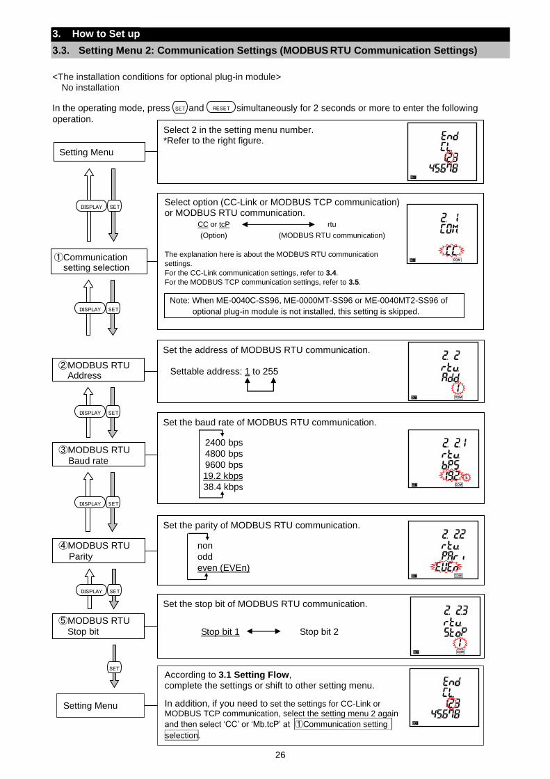
Setting Menu 2: Communication Settings (MODBUS RTU Communication Settings)
<The installation conditions for optional plug-in module> No installation
In the operating mode, press and simultaneously for 2 seconds or more to enter the following
operation.
SET RESET
According to 3.1 Setting Flow, complete the settings or shift to other setting menu.
In addition, if you need to set the settings for CC-Link or
MODBUS TCP communication, select the setting menu 2 again
and then select ‘CC’ or ‘Mb.tcP’ at ①Communication setting
selection.
Setting Menu
Set the parity of MODBUS RTU communication.
④MODBUS RTU
Parity
non
odd
even (EVEn)
Set the baud rate of MODBUS RTU communication.
③MODBUS RTU
Baud rate
2400 bps
4800 bps
9600 bps
19.2 kbps
38.4 kbps
Set the address of MODBUS RTU communication.
Settable address: 1 to 255
②MODBUS RTU Address
Set the stop bit of MODBUS RTU communication.
⑤MODBUS RTU
Stop bit Stop bit 1 Stop bit 2
Select 2 in the setting menu number. *Refer to the right figure. Setting Menu
Select option (CC-Link or MODBUS TCP communication) or MODBUS RTU communication.
CC or tcP rtu
(Option) (MODBUS RTU communication)
The explanation here is about the MODBUS RTU communication
settings.
For the CC-Link communication settings, refer to 3.4.
For the MODBUS TCP communication settings, refer to 3.5.
①Communication setting selection
Note: When ME-0040C-SS96, ME-0000MT-SS96 or ME-0040MT2-SS96 of
optional plug-in module is not installed, this setting is skipped.
SETDISPLAY
SET
SETDISPLAY
SETDISPLAY
SETDISPLAY
SETDISPLAY
27
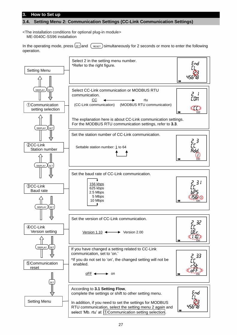
Set the station number of CC-Link communication. Settable station number: 1 to 64
②CC-Link Station number
3. How to Set up
Setting Menu 2: Communication Settings (CC-Link Communication Settings)
<The installation conditions for optional plug-in module>
ME-0040C-SS96 installation
In the operating mode, press and simultaneously for 2 seconds or more to enter the following
operation.
Select CC-Link communication or MODBUS RTU
communication.
CC rtu
(CC-Link communication) (MODBUS RTU communication)
The explanation here is about CC-Link communication settings. For the MODBUS RTU communication settings, refer to 3.3.
①Communication setting selection
SET RESET
Select 2 in the setting menu number. *Refer to the right figure. Setting Menu
SETDISPLAY
SETDISPLAY
SETDISPLAY
SET
Set the baud rate of CC-Link communication.
③CC-Link Baud rate
156 kbps 625 kbps 2.5 Mbps
5 Mbps 10 Mbps
Set the version of CC-Link communication.
④CC-Link Version setting Version 1.10 Version 2.00
According to 3.1 Setting Flow, complete the settings or shift to other setting menu. In addition, if you need to set the settings for MODBUS RTU communication, select the setting menu 2 again and
select ‘Mb. rtu’ at ①Communication setting selection.
Setting Menu
If you have changed a setting related to CC-Link communication, set to ‘on.’
*If you do not set to ‘on’, the changed setting will not be enabled. ⑤Communication
reset
oFF on
SETDISPLAY
SETDISPLAY
28
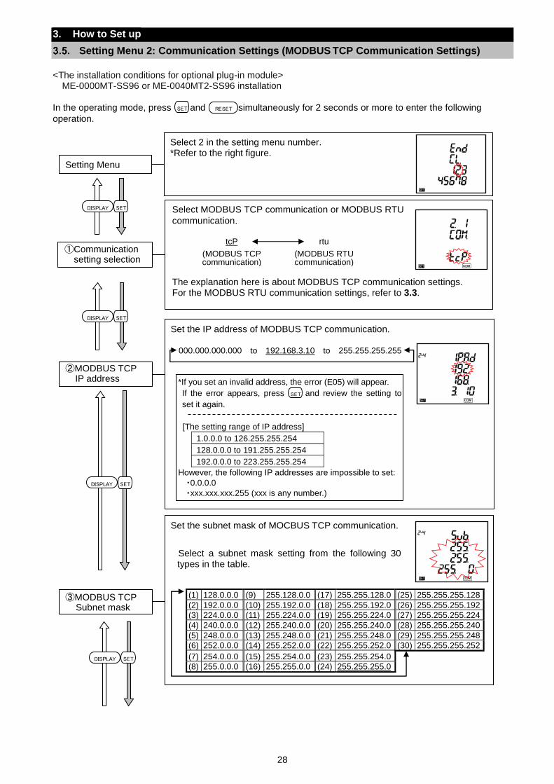
3. How to Set up
Setting Menu 2: Communication Settings (MODBUS TCP Communication Settings)
<The installation conditions for optional plug-in module>
ME-0000MT-SS96 or ME-0040MT2-SS96 installation
In the operating mode, press and simultaneously for 2 seconds or more to enter the following
operation.
Select MODBUS TCP communication or MODBUS RTU
communication.
tcP rtu
(MODBUS TCP communication)
(MODBUS RTU communication)
The explanation here is about MODBUS TCP communication settings. For the MODBUS RTU communication settings, refer to 3.3.
①Communication setting selection
SET RESET
Select 2 in the setting menu number. *Refer to the right figure. Setting Menu
SETDISPLAY
SETDISPLAY
Set the IP address of MODBUS TCP communication.
②MODBUS TCP IP address *If you set an invalid address, the error (E05) will appear.
If the error appears, press and review the setting to
set it again.
[The setting range of IP address]
1.0.0.0 to 126.255.255.254
128.0.0.0 to 191.255.255.254
192.0.0.0 to 223.255.255.254
However, the following IP addresses are impossible to set:
・0.0.0.0
・xxx.xxx.xxx.255 (xxx is any number.)
SET
000.000.000.000 to 192.168.3.10 to 255.255.255.255
Set the subnet mask of MOCBUS TCP communication.
Select a subnet mask setting from the following 30 types in the table.
(1) 128.0.0.0 (9) 255.128.0.0 (17) 255.255.128.0 (25) 255.255.255.128
(2) 192.0.0.0 (10) 255.192.0.0 (18) 255.255.192.0 (26) 255.255.255.192
(3) 224.0.0.0 (11) 255.224.0.0 (19) 255.255.224.0 (27) 255.255.255.224
(4) 240.0.0.0 (12) 255.240.0.0 (20) 255.255.240.0 (28) 255.255.255.240
(5) 248.0.0.0 (13) 255.248.0.0 (21) 255.255.248.0 (29) 255.255.255.248
(6) 252.0.0.0 (14) 255.252.0.0 (22) 255.255.252.0 (30) 255.255.255.252
(7) 254.0.0.0 (15) 255.254.0.0 (23) 255.255.254.0
(8) 255.0.0.0 (16) 255.255.0.0 (24) 255.255.255.0
③MODBUS TCP Subnet mask
SETDISPLAY
SETDISPLAY
29
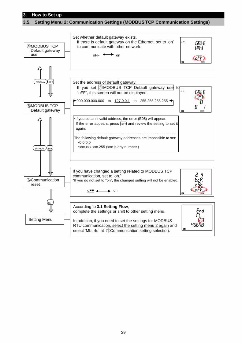
3. How to Set up
3.5. Setting Menu 2: Communication Settings (MODBUS TCP Communication Settings)
SET
SETDISPLAY
SETDISPLAY
Set whether default gateway exists. If there is default gateway on the Ethernet, set to ‘on’ to communicate with other network. oFF on
④MODBUS TCP Default gateway use
Set the address of default gateway.
If you set ④MODBUS TCP Default gateway use to
“oFF”, this screen will not be displayed.
⑤MODBUS TCP
Default gateway
*If you set an invalid address, the error (E05) will appear.
If the error appears, press and review the setting to set it
again.
The following default gateway addresses are impossible to set:
・0.0.0.0
・xxx.xxx.xxx.255 (xxx is any number.)
000.000.000.000 to 127.0.0.1 to 255.255.255.255
SET
If you have changed a setting related to MODBUS TCP communication, set to ‘on.’ *If you do not set to “on”, the changed setting will not be enabled. ⑥Communication
reset
oFF on
According to 3.1 Setting Flow, complete the settings or shift to other setting menu. In addition, if you need to set the settings for MODBUS RTU communication, select the setting menu 2 again and
select ‘Mb. rtu’ at ①Communication setting selection.
Setting Menu
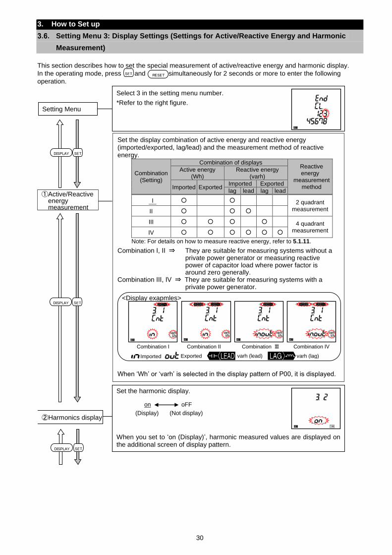
30
3. How to Set up
Setting Menu 3: Display Settings (Settings for Active/Reactive Energy and Harmonic
Measurement)
This section describes how to set the special measurement of active/reactive energy and harmonic display.
In the operating mode, press and simultaneously for 2 seconds or more to enter the following
operation.
SET RESET
SETDISPLAY
①Active/Reactive energy measurement
Set the display combination of active energy and reactive energy (imported/exported, lag/lead) and the measurement method of reactive energy.
Combination (Setting)
Combination of displays Reactive energy
measurement method
Active energy (Wh)
Reactive energy (varh)
Imported Exported Imported Exported
lag lead lag lead
Ⅰ 2 quadrant
measurement Ⅱ
Ⅲ 4 quadrant measurement Ⅳ
Note: For details on how to measure reactive energy, refer to 5.1.11.
Combination Ⅰ, Ⅱ ⇒ They are suitable for measuring systems without a private power generator or measuring reactive power of capacitor load where power factor is around zero generally.
Combination Ⅲ, Ⅳ ⇒ They are suitable for measuring systems with a private power generator.
<Display exapmles>
When ‘Wh’ or ‘varh’ is selected in the display pattern of P00, it is displayed.
Select 3 in the setting menu number.
*Refer to the right figure. Setting Menu
Set the harmonic display.
When you set to ‘on (Display)’, harmonic measured values are displayed on the additional screen of display pattern.
②Harmonics display
on oFF
(Display) (Not display)
Combination Ⅰ Combination Ⅱ Combination Ⅲ Combination Ⅳ
varh (lag) Exported Imported varh (lead)
SETDISPLAY
SETDISPLAY
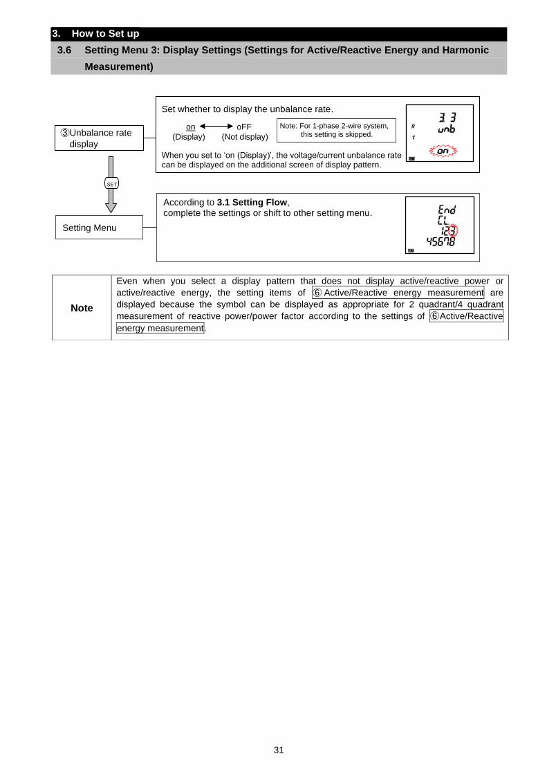
31
3. How to Set up
3.6 Setting Menu 3: Display Settings (Settings for Active/Reactive Energy and Harmonic
Measurement)
Note
Even when you select a display pattern that does not display active/reactive power or
active/reactive energy, the setting items of ⑥ Active/Reactive energy measurement are
displayed because the symbol can be displayed as appropriate for 2 quadrant/4 quadrant
measurement of reactive power/power factor according to the settings of ⑥Active/Reactive
energy measurement.
According to 3.1 Setting Flow, complete the settings or shift to other setting menu.
Setting Menu
SET
Set whether to display the unbalance rate.
When you set to ‘on (Display)’, the voltage/current unbalance rate can be displayed on the additional screen of display pattern.
③Unbalance rate
display
on oFF
(Display) (Not display)
Note: For 1-phase 2-wire system, this setting is skipped.
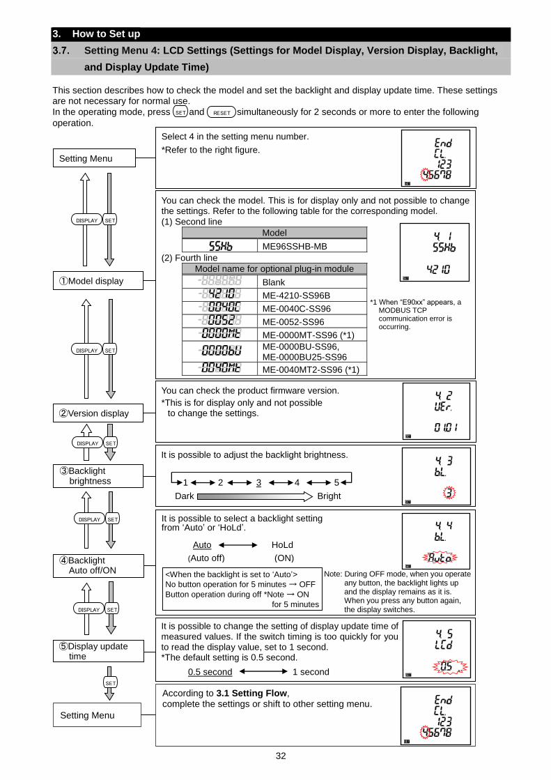
32
You can check the model. This is for display only and not possible to change the settings. Refer to the following table for the corresponding model.
(1) Second line
Model
ME96SSHB-MB
(2) Fourth line
Model name for optional plug-in module
Blank
ME-4210-SS96B
ME-0040C-SS96
ME-0052-SS96
ME-0000MT-SS96 (*1)
ME-0000BU-SS96, ME-0000BU25-SS96
ME-0040MT2-SS96 (*1)
①Model display
*1 When “E90xx” appears, a MODBUS TCP communication error is occurring.
3. How to Set up
Setting Menu 4: LCD Settings (Settings for Model Display, Version Display, Backlight,
and Display Update Time)
This section describes how to check the model and set the backlight and display update time. These settings are not necessary for normal use.
In the operating mode, press and simultaneously for 2 seconds or more to enter the following
operation.
SET RESET
Select 4 in the setting menu number.
*Refer to the right figure. Setting Menu
It is possible to change the setting of display update time of measured values. If the switch timing is too quickly for you to read the display value, set to 1 second. *The default setting is 0.5 second.
0.5 second 1 second
⑤Display update time
It is possible to select a backlight setting from ‘Auto’ or ‘HoLd’.
④Backlight
Auto off/ON
Auto HoLd
<When the backlight is set to ‘Auto’>
No button operation for 5 minutes → OFF
Button operation during off *Note → ON
for 5 minutes
Note: During OFF mode, when you operate any button, the backlight lights up and the display remains as it is. When you press any button again, the display switches.
(Auto off) (ON)
It is possible to adjust the backlight brightness.
③Backlight brightness 1 2 3 4 5
Dark Bright
You can check the product firmware version.
*This is for display only and not possible to change the settings.
②Version display
According to 3.1 Setting Flow, complete the settings or shift to other setting menu.
Setting Menu
SET
SETDISPLAY
SETDISPLAY
SETDISPLAY
SETDISPLAY
SETDISPLAY
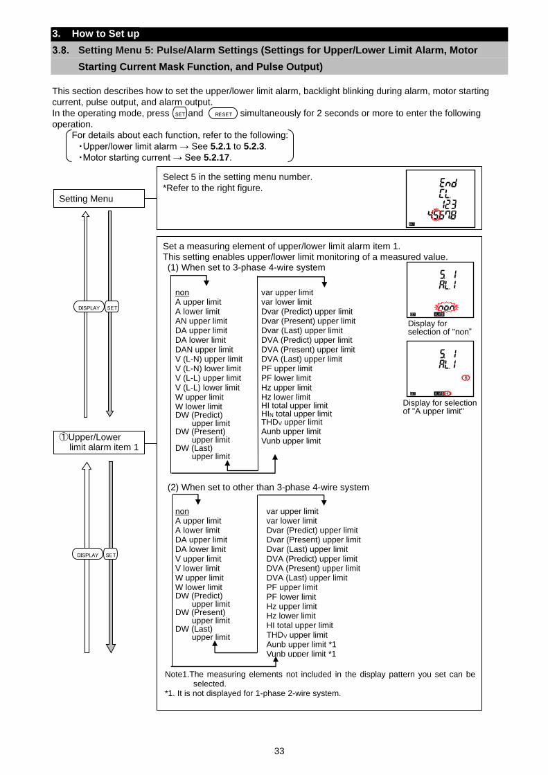
33
Set a measuring element of upper/lower limit alarm item 1. This setting enables upper/lower limit monitoring of a measured value. (1) When set to 3-phase 4-wire system
(2) When set to other than 3-phase 4-wire system
①Upper/Lower limit alarm item 1
Note1.The measuring elements not included in the display pattern you set can be selected.
*1. It is not displayed for 1-phase 2-wire system.
Display for selection of "A upper limit"
var upper limit var lower limit Dvar (Predict) upper limit Dvar (Present) upper limit Dvar (Last) upper limit DVA (Predict) upper limit DVA (Present) upper limit DVA (Last) upper limit PF upper limit PF lower limit Hz upper limit Hz lower limit HI total upper limit HIN total upper limit THDV upper limit Aunb upper limit Vunb upper limit
non A upper limit A lower limit AN upper limit DA upper limit DA lower limit DAN upper limit V (L-N) upper limit V (L-N) lower limit V (L-L) upper limit V (L-L) lower limit W upper limit W lower limit DW (Predict)
upper limit DW (Present)
upper limit DW (Last)
upper limit
non A upper limit A lower limit DA upper limit DA lower limit V upper limit V lower limit W upper limit W lower limit DW (Predict)
upper limit DW (Present)
upper limit DW (Last)
upper limit
var upper limit var lower limit Dvar (Predict) upper limit Dvar (Present) upper limit Dvar (Last) upper limit DVA (Predict) upper limit DVA (Present) upper limit DVA (Last) upper limit PF upper limit PF lower limit Hz upper limit Hz lower limit HI total upper limit THDV upper limit Aunb upper limit *1 Vunb upper limit *1
Display for selection of "non”
3. How to Set up
Setting Menu 5: Pulse/Alarm Settings (Settings for Upper/Lower Limit Alarm, Motor
Starting Current Mask Function, and Pulse Output)
This section describes how to set the upper/lower limit alarm, backlight blinking during alarm, motor starting
current, pulse output, and alarm output.
In the operating mode, press and simultaneously for 2 seconds or more to enter the following
operation.
For details about each function, refer to the following:
・Upper/lower limit alarm → See 5.2.1 to 5.2.3.
・Motor starting current → See 5.2.17.
SET RESET
SETDISPLAY
Select 5 in the setting menu number.
*Refer to the right figure.
Setting Menu
SETDISPLAY
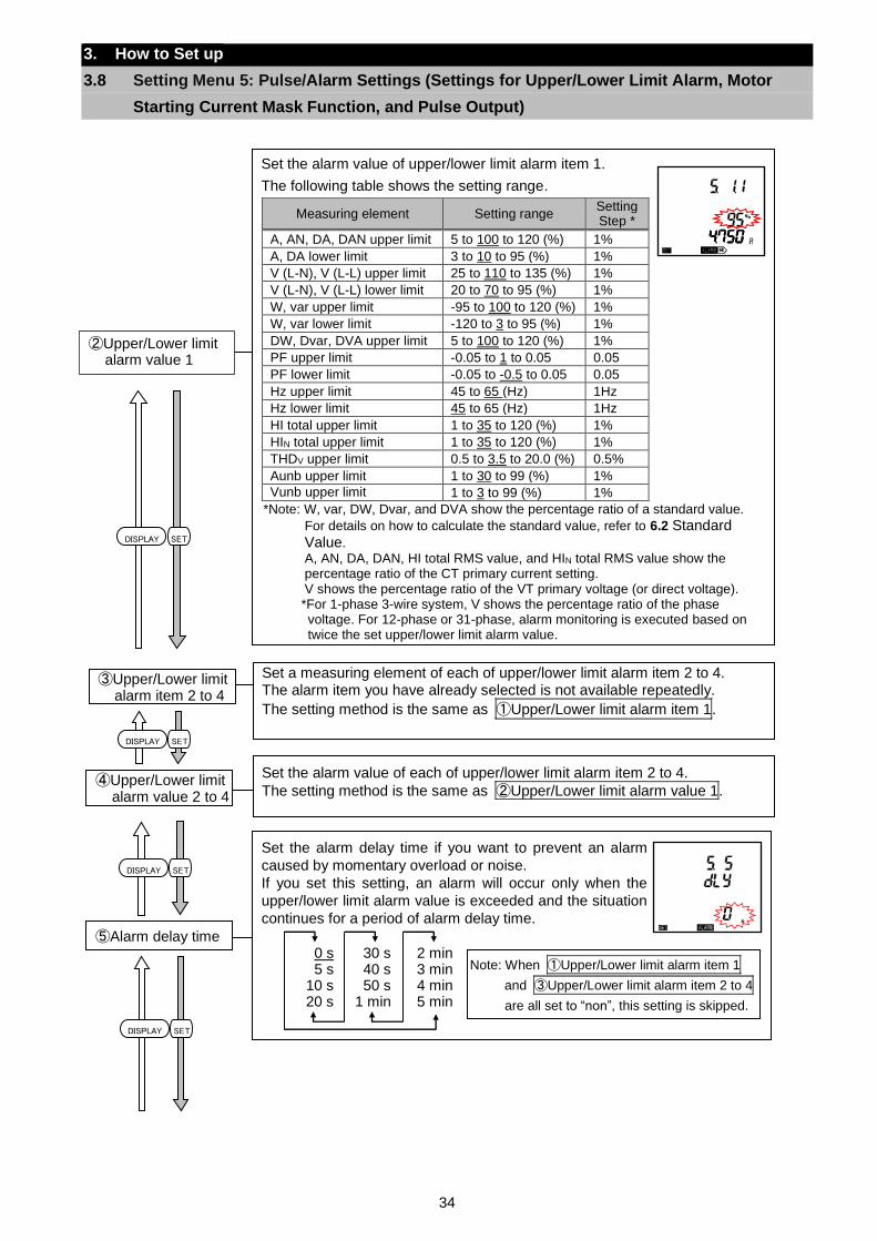
34
Set the alarm delay time if you want to prevent an alarm
caused by momentary overload or noise.
If you set this setting, an alarm will occur only when the
upper/lower limit alarm value is exceeded and the situation
continues for a period of alarm delay time.
⑤Alarm delay time 0 s 5 s
10 s 20 s
30 s 40 s 50 s
1 min
2 min 3 min 4 min 5 min
Note: When ①Upper/Lower limit alarm item 1
and ③Upper/Lower limit alarm item 2 to 4
are all set to “non”, this setting is skipped.
3. How to Set up
3.8 Setting Menu 5: Pulse/Alarm Settings (Settings for Upper/Lower Limit Alarm, Motor
Starting Current Mask Function, and Pulse Output)
SETDISPLAY
Set the alarm value of each of upper/lower limit alarm item 2 to 4.
The setting method is the same as ②Upper/Lower limit alarm value 1.
④Upper/Lower limit alarm value 2 to 4
Set a measuring element of each of upper/lower limit alarm item 2 to 4. The alarm item you have already selected is not available repeatedly.
The setting method is the same as ①Upper/Lower limit alarm item 1.
③Upper/Lower limit alarm item 2 to 4
②Upper/Lower limit alarm value 1
Set the alarm value of upper/lower limit alarm item 1.
The following table shows the setting range.
Measuring element Setting range Setting Step *
A, AN, DA, DAN upper limit 5 to 100 to 120 (%) 1%
A, DA lower limit 3 to 10 to 95 (%) 1%
V (L-N), V (L-L) upper limit 25 to 110 to 135 (%) 1%
V (L-N), V (L-L) lower limit 20 to 70 to 95 (%) 1%
W, var upper limit -95 to 100 to 120 (%) 1%
W, var lower limit -120 to 3 to 95 (%) 1%
DW, Dvar, DVA upper limit 5 to 100 to 120 (%) 1%
PF upper limit -0.05 to 1 to 0.05 0.05
PF lower limit -0.05 to -0.5 to 0.05 0.05
Hz upper limit 45 to 65 (Hz) 1Hz
Hz lower limit 45 to 65 (Hz) 1Hz
HI total upper limit 1 to 35 to 120 (%) 1%
HIN total upper limit 1 to 35 to 120 (%) 1%
THDV upper limit 0.5 to 3.5 to 20.0 (%) 0.5%
Aunb upper limit 1 to 30 to 99 (%) 1%
Vunb upper limit 1 to 3 to 99 (%) 1%
*Note: W, var, DW, Dvar, and DVA show the percentage ratio of a standard value.
For details on how to calculate the standard value, refer to 6.2 Standard Value.
A, AN, DA, DAN, HI total RMS value, and HIN total RMS value show the percentage ratio of the CT primary current setting. V shows the percentage ratio of the VT primary voltage (or direct voltage). *For 1-phase 3-wire system, V shows the percentage ratio of the phase voltage. For 12-phase or 31-phase, alarm monitoring is executed based on twice the set upper/lower limit alarm value.
SETDISPLAY
SETDISPLAY
SETDISPLAY
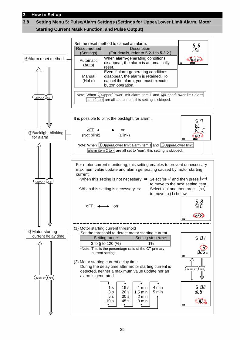
35
For motor current monitoring, this setting enables to prevent unnecessary
maximum value update and alarm generating caused by motor starting
current.
・When this setting is not necessary ⇒ Select ‘oFF’ and then press to move to the next setting item.
・When this setting is necessary ⇒ Select ‘on’ and then press
to move to (1) below.
(1) Motor starting current threshold Set the threshold to detect motor starting current.
Setting range Setting step *Note
3 to 5 to 120 (%) 1%
*Note: This is the percentage ratio of the CT primary current setting.
(2) Motor starting current delay time
During the delay time after motor starting current is detected, neither a maximum value update nor an alarm is generated.
⑧Motor starting current delay time
oFF on
1 s 3 s 5 s
10 s
15 s 20 s 30 s 45 s
4 min 5 min
SET
SET
SETDISPLAY
1 min 1.5 min
2 min 3 min
3. How to Set up
3.8 Setting Menu 5: Pulse/Alarm Settings (Settings for Upper/Lower Limit Alarm, Motor
Starting Current Mask Function, and Pulse Output)
Set the reset method to cancel an alarm.
Reset method (Settings)
Description (For details, refer to 5.2.1 to 5.2.2.)
Automatic (Auto)
When alarm-generating conditions disappear, the alarm is automatically reset.
Manual (HoLd)
Even if alarm-generating conditions disappear, the alarm is retained. To cancel the alarm, you must execute button operation.
Note: When ①Upper/Lower limit alarm item 1 and ③Upper/Lower limit alarm
item 2 to 4 are all set to ‘non’, this setting is skipped.
⑥Alarm reset method
SETDISPLAY
SETDISPLAY
It is possible to blink the backlight for alarm.
⑦Backlight blinking for alarm
oFF on
(Not blink) (Blink)
Note: When ①Upper/Lower limit alarm item 1 and ③Upper/Lower limit
alarm item 2 to 4 are all set to “non”, this setting is skipped.
SETDISPLAY
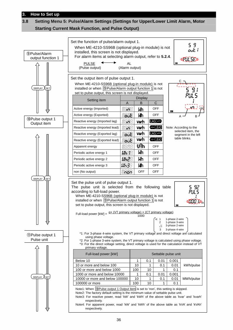
36
Set the output item of pulse output 1.
When ME-4210-SS96B (optional plug-in module) is not
installed or when ⑨Pulse/Alarm output function 1 is not
set to pulse output, this screen is not displayed.
Setting item Display
A B C
Active energy (Imported) OFF
Active energy (Exported) OFF
Reactive energy (Imported lag)
Reactive energy (Imported lead)
Reactive energy (Exported lag)
Reactive energy (Exported lead)
Apparent energy OFF
Periodic active energy 1 OFF
Periodic active energy 2 OFF
Periodic active energy 3 OFF
non (No output) OFF OFF
⑩Pulse output 1 Output item
Note: According to the selected item, the segment in the left table blinks.
A B
C
3. How to Set up
3.8 Setting Menu 5: Pulse/Alarm Settings (Settings for Upper/Lower Limit Alarm, Motor
Starting Current Mask Function, and Pulse Output)
SETDISPLAY
Set the function of pulse/alarm output 1.
When ME-4210-SS96B (optional plug-in module) is not installed, this screen is not displayed. For alarm items at selecting alarm output, refer to 5.2.4.
⑨Pulse/Alarm output function 1
PULSE AL (Pulse output) (Alarm output)
Set the pulse unit of pulse output 1. The pulse unit is selected from the following table according to full-load power.
When ME-4210-SS96B (optional plug-in module) is not
installed or when ⑨Pulse/Alarm output function 1 is not
set to pulse output, this screen is not displayed.
*1: For 3-phase 4-wire system, the VT primary voltage and direct voltage are calculated using phase voltage.
*2: For 1-phase 3-wire system, the VT primary voltage is calculated using phase voltage. *3: For the direct voltage setting, direct voltage is used for the calculation instead of VT
primary voltage.
Full-load power [kW] Settable pulse unit
Below 10 1 0.1 0.01 0.001
kWh/pulse 10 or more and below 100 10 1 0.1 0.01
100 or more and below 1000 100 10 1 0.1
1000 or more and below 10000 1 0.1 0.01 0.001
MWh/pulse 10000 or more and below 100000 10 1 0.1 0.01
100000 or more 100 10 1 0.1
Note1: When ⑩Pulse output 1 Output item is set to ‘non’, this setting is skipped.
Note2: The factory default setting is the minimum value of settable pulse unit.
Note3: For reactive power, read ‘kW’ and ‘kWh’ of the above table as ‘kvar’ and ‘kvarh’
respectively.
Note4: For apparent power, read ‘kW’ and ‘kWh’ of the above table as ‘kVA’ and ‘kVAh’
respectively.
⑪Pulse output 1
Pulse unit
α: 1 1-phase 2-wire 2 1-phase 3-wire
3 3-phase 2-wire
3 3-phase 4-wire
Full-load power [kW] = α× (VT primary voltage) × (CT primary voltage)
1000
SETDISPLAY
SETDISPLAY
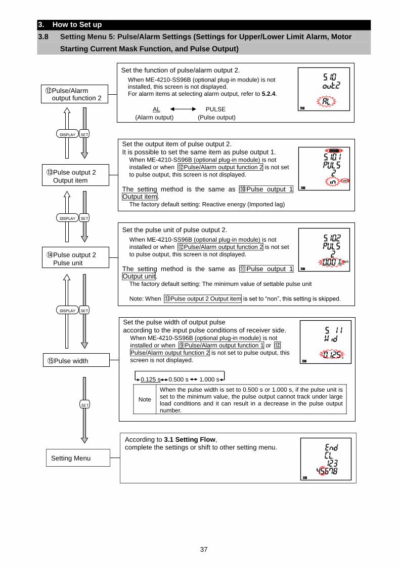
37
Set the pulse unit of pulse output 2.
When ME-4210-SS96B (optional plug-in module) is not
installed or when ⑫Pulse/Alarm output function 2 is not set
to pulse output, this screen is not displayed.
The setting method is the same as ⑪Pulse output 1 Output unit.
The factory default setting: The minimum value of settable pulse unit
Note: When ⑬Pulse output 2 Output item is set to “non”, this setting is skipped.
⑭Pulse output 2
Pulse unit
3. How to Set up
3.8 Setting Menu 5: Pulse/Alarm Settings (Settings for Upper/Lower Limit Alarm, Motor
Starting Current Mask Function, and Pulse Output)
According to 3.1 Setting Flow, complete the settings or shift to other setting menu.
Setting Menu
Set the function of pulse/alarm output 2.
When ME-4210-SS96B (optional plug-in module) is not installed, this screen is not displayed. For alarm items at selecting alarm output, refer to 5.2.4.
⑫Pulse/Alarm output function 2
AL PULSE
(Alarm output) (Pulse output)
Set the output item of pulse output 2.
It is possible to set the same item as pulse output 1. When ME-4210-SS96B (optional plug-in module) is not
installed or when ⑫Pulse/Alarm output function 2 is not set
to pulse output, this screen is not displayed.
The setting method is the same as ⑩Pulse output 1 Output item.
The factory default setting: Reactive energy (Imported lag)
⑬Pulse output 2
Output item
SETDISPLAY
SETDISPLAY
SETDISPLAY
SET
Set the pulse width of output pulse
according to the input pulse conditions of receiver side. When ME-4210-SS96B (optional plug-in module) is not
installed or when ⑨Pulse/Alarm output function 1 or ⑫Pulse/Alarm output function 2 is not set to pulse output, this
screen is not displayed.
Note
When the pulse width is set to 0.500 s or 1.000 s, if the pulse unit is set to the minimum value, the pulse output cannot track under large load conditions and it can result in a decrease in the pulse output number.
⑮Pulse width
0.125 s 0.500 s 1.000 s
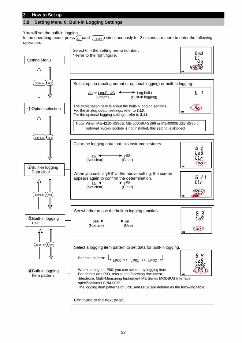
38
3. How to Set up
Setting Menu 6: Built-in Logging Settings
You will set the built-in logging.
In the operating mode, press and simultaneously for 2 seconds or more to enter the following
operation.
Select option (analog output or optional logging) or built-in logging.
Ao or Log.PLUG Log.buiLt (Option) (Built-in logging)
The explanation here is about the built-in logging settings.
For the analog output settings, refer to 3.10. For the optional logging settings, refer to 3.11.
①Option selection
SET RESET
Select 6 in the setting menu number.
*Refer to the right figure.
Setting Menu
Clear the logging data that this instrument stores.
no yES (Not clear) (Clear)
When you select ‘yES’ at the above setting, the screen appears again to confirm the determination.
no yES (Not clear) (Clear)
②Built-in logging Data clear
SETDISPLAY
Set whether to use the built-in logging function.
oFF on
(Not use) (Use)
③Built-in logging use
Note: When ME-4210-SS96B, ME-0000BU-SS96 or ME-0000BU25-SS96 of
optional plug-in module is not installed, this setting is skipped.
SETDISPLAYSelect a logging item pattern to set data for built-in logging.
Settable pattern:
When setting to LP00, you can select any logging item. For details on LP00, refer to the following document.
∙Electronic Multi-Measuring Instrument ME Series MODBUS Interface
specifications LSPM-0075 The logging item patterns of LP01 and LP02 are defined as the following table.
Continued to the next page.
④Built-in logging Item pattern
LP00 LP01 LP02
SETDISPLAY
SETDISPLAY
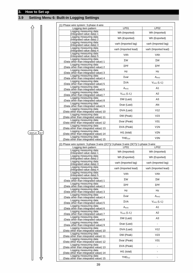
39
3. How to Set up
3.9 Setting Menu 6: Built-in Logging Settings
(1) Phase wire system: 3-phase 4-wire
Logging item pattern LP01 LP02
Logging measuring data (Integrated value data) 1
Wh (Imported) Wh (Imported)
Logging measuring data (Integrated value data) 2
Wh (Exported) Wh (Exported)
Logging measuring data (Integrated value data) 3
varh (Imported lag) varh (Imported lag)
Logging measuring data (Integrated value data) 4
varh (Imported lead) varh (Imported lead)
Logging measuring data (Integrated value data) 5
VAh VAh
Logging measuring data (Data other than integrated value) 1
ΣW ΣW
Logging measuring data (Data other than integrated value) 2
ΣPF ΣPF
Logging measuring data (Data other than integrated value) 3
Hz Hz
Logging measuring data (Data other than integrated value) 4
Σvar AAVG
Logging measuring data (Data other than integrated value) 5
ΣVA VAVG (L-L)
Logging measuring data (Data other than integrated value) 6
AAVG A1
Logging measuring data (Data other than integrated value) 7
VAVG (L-L) A2
Logging measuring data (Data other than integrated value) 8
DW (Last) A3
Logging measuring data (Data other than integrated value) 9
Dvar (Last) AN
Logging measuring data (Data other than integrated value) 10
DVA (Last) V12
Logging measuring data (Data other than integrated value) 11
DW (Peak) V23
Logging measuring data (Data other than integrated value) 12
Dvar (Peak) V31
Logging measuring data (Data other than integrated value) 13
DVA (Peak) V1N
Logging measuring data (Data other than integrated value) 14
HI1 (total) V2N
Logging measuring data (Data other than integrated value) 15
THDv1N V3N
(2) Phase wire system: 3-phase 3-wire (2CT)/ 3-phase 3-wire (3CT)/ 1-phase 3-wire
Logging item pattern LP01 LP02
Logging measuring data (Integrated value data) 1
Wh (Imported) Wh (Imported)
Logging measuring data (Integrated value data) 2
Wh (Exported) Wh (Exported)
Logging measuring data (Integrated value data) 3
varh (Imported lag) varh (Imported lag)
Logging measuring data (Integrated value data) 4
varh (Imported lead) varh (Imported lead)
Logging measuring data (Integrated value data) 5
VAh VAh
Logging measuring data (Data other than integrated value) 1
ΣW ΣW
Logging measuring data (Data other than integrated value) 2
ΣPF ΣPF
Logging measuring data (Data other than integrated value) 3
Hz Hz
Logging measuring data (Data other than integrated value) 4
Σvar AAVG
Logging measuring data (Data other than integrated value) 5
ΣVA VAVG (L-L)
Logging measuring data (Data other than integrated value) 6
AAVG A1
Logging measuring data (Data other than integrated value) 7
VAVG (L-L) A2
Logging measuring data (Data other than integrated value) 8
DW (Last) A3
Logging measuring data (Data other than integrated value) 9
Dvar (Last) -
Logging measuring data (Data other than integrated value) 10
DVA (Last) V12
Logging measuring data (Data other than integrated value) 11
DW (Peak) V23
Logging measuring data (Data other than integrated value) 12
Dvar (Peak) V31
Logging measuring data (Data other than integrated value) 13
DVA (Peak) -
Logging measuring data (Data other than integrated value) 14
HI1 (total) -
Logging measuring data (Data other than integrated value) 15
THDv12 -
SETDISPLAY
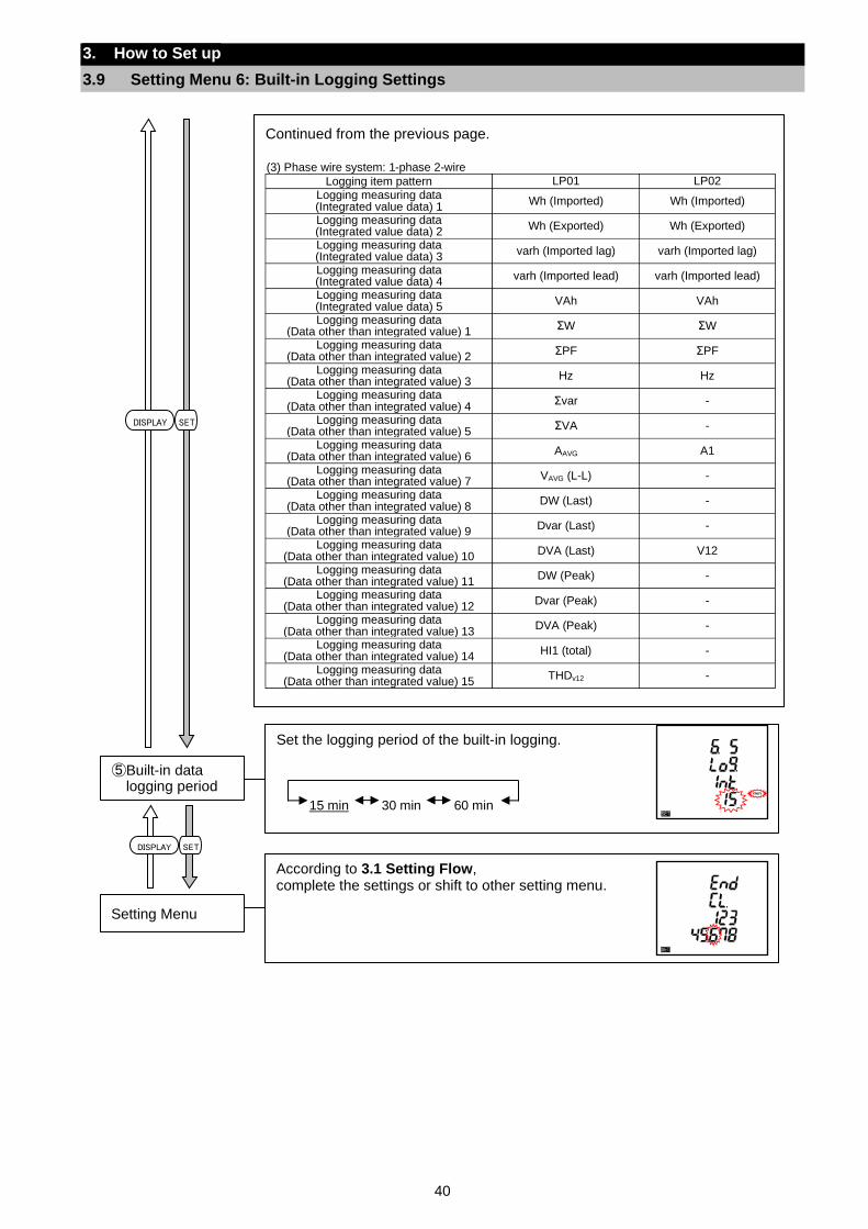
40
3. How to Set up
3.9 Setting Menu 6: Built-in Logging Settings
Set the logging period of the built-in logging.
15 min 30 min 60 min
⑤Built-in data logging period
According to 3.1 Setting Flow, complete the settings or shift to other setting menu.
Setting Menu
Continued from the previous page.
(3) Phase wire system: 1-phase 2-wire
Logging item pattern LP01 LP02
Logging measuring data (Integrated value data) 1
Wh (Imported) Wh (Imported)
Logging measuring data (Integrated value data) 2
Wh (Exported) Wh (Exported)
Logging measuring data (Integrated value data) 3
varh (Imported lag) varh (Imported lag)
Logging measuring data (Integrated value data) 4
varh (Imported lead) varh (Imported lead)
Logging measuring data (Integrated value data) 5
VAh VAh
Logging measuring data (Data other than integrated value) 1
ΣW ΣW
Logging measuring data (Data other than integrated value) 2
ΣPF ΣPF
Logging measuring data (Data other than integrated value) 3
Hz Hz
Logging measuring data (Data other than integrated value) 4
Σvar -
Logging measuring data (Data other than integrated value) 5
ΣVA -
Logging measuring data (Data other than integrated value) 6
AAVG A1
Logging measuring data (Data other than integrated value) 7
VAVG (L-L) -
Logging measuring data (Data other than integrated value) 8
DW (Last) -
Logging measuring data (Data other than integrated value) 9
Dvar (Last) -
Logging measuring data (Data other than integrated value) 10
DVA (Last) V12
Logging measuring data (Data other than integrated value) 11
DW (Peak) -
Logging measuring data (Data other than integrated value) 12
Dvar (Peak) -
Logging measuring data (Data other than integrated value) 13
DVA (Peak) -
Logging measuring data (Data other than integrated value) 14
HI1 (total) -
Logging measuring data (Data other than integrated value) 15
THDv12 -
SETDISPLAY
SETDISPLAY
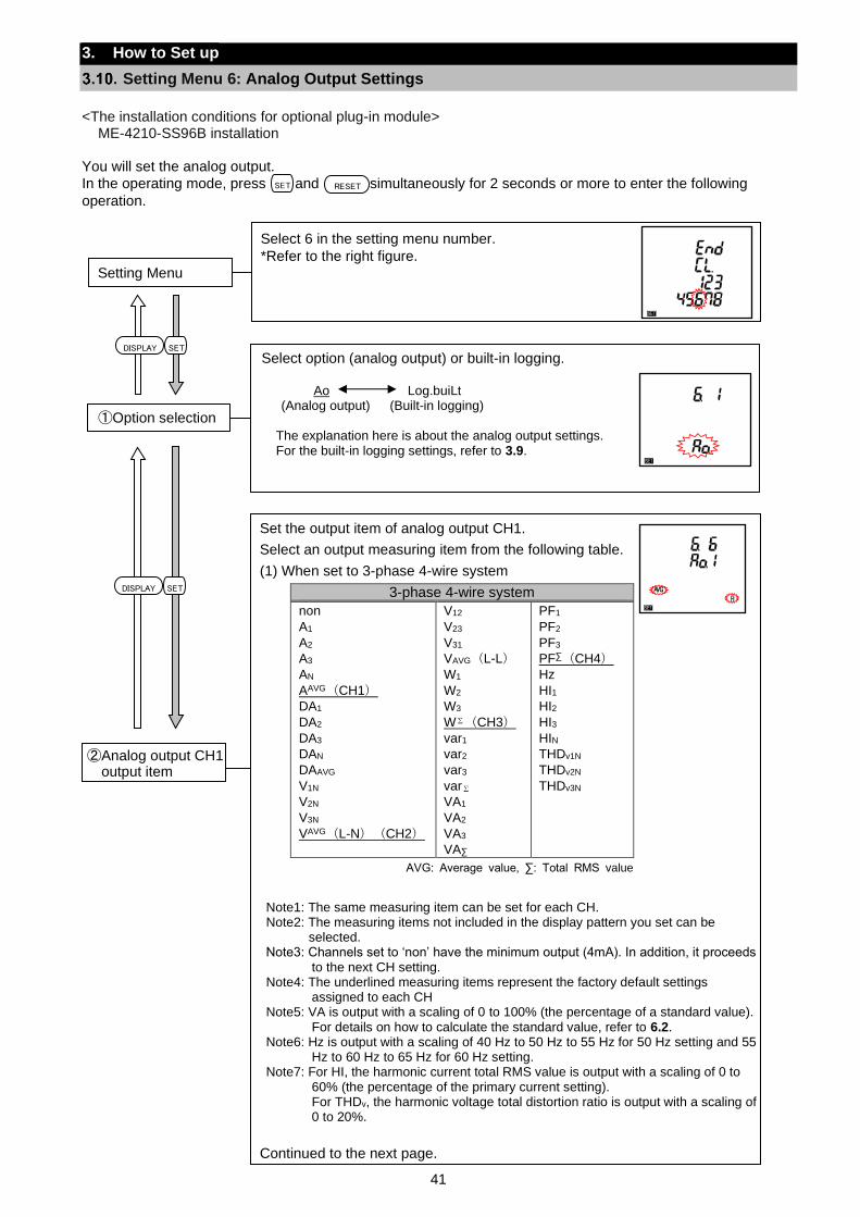
41
3. How to Set up
Setting Menu 6: Analog Output Settings
<The installation conditions for optional plug-in module>
ME-4210-SS96B installation You will set the analog output.
In the operating mode, press and simultaneously for 2 seconds or more to enter the following
operation.
SET RESET
Select option (analog output) or built-in logging.
Ao Log.buiLt (Analog output) (Built-in logging)
The explanation here is about the analog output settings. For the built-in logging settings, refer to 3.9.
①Option selection
SETDISPLAY
SETDISPLAY
Select 6 in the setting menu number.
*Refer to the right figure.
Setting Menu
Set the output item of analog output CH1.
Select an output measuring item from the following table.
(1) When set to 3-phase 4-wire system
3-phase 4-wire system
non
A1
A2
A3
AN
AAVG(CH1)
DA1
DA2
DA3
DAN
DAAVG
V1N
V2N
V3N
VAVG(L-N)(CH2)
V12
V23
V31
VAVG(L-L)
W1
W2
W3
W∑(CH3)
var1
var2
var3
var∑
VA1
VA2
VA3
VA∑
PF1
PF2
PF3
PF∑(CH4)
Hz
HI1
HI2
HI3
HIN
THDv1N
THDv2N
THDv3N
AVG: Average value, ∑: Total RMS value
Continued to the next page.
次のページへ
②Analog output CH1 output item
Note1: The same measuring item can be set for each CH. Note2: The measuring items not included in the display pattern you set can be
selected. Note3: Channels set to ‘non’ have the minimum output (4mA). In addition, it proceeds
to the next CH setting. Note4: The underlined measuring items represent the factory default settings
assigned to each CH Note5: VA is output with a scaling of 0 to 100% (the percentage of a standard value).
For details on how to calculate the standard value, refer to 6.2. Note6: Hz is output with a scaling of 40 Hz to 50 Hz to 55 Hz for 50 Hz setting and 55
Hz to 60 Hz to 65 Hz for 60 Hz setting. Note7: For HI, the harmonic current total RMS value is output with a scaling of 0 to
60% (the percentage of the primary current setting). For THDv, the harmonic voltage total distortion ratio is output with a scaling of 0 to 20%.
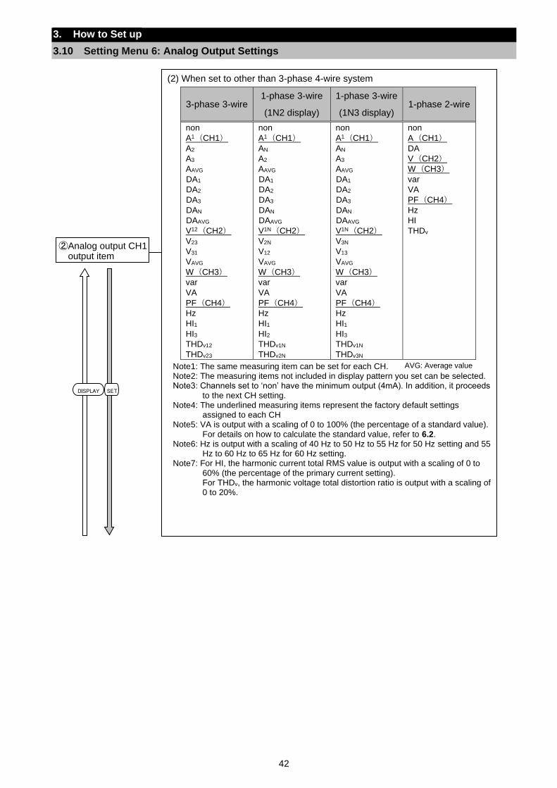
42
3. How to Set up
3.10 Setting Menu 6: Analog Output Settings
SETDISPLAY
(2) When set to other than 3-phase 4-wire system
3-phase 3-wire 1-phase 3-wire
(1N2 display)
1-phase 3-wire
(1N3 display) 1-phase 2-wire
non
A1(CH1)
A2
A3
AAVG
DA1
DA2
DA3
DAN
DAAVG
V12(CH2)
V23
V31
VAVG
W(CH3)
var
VA
PF(CH4)
Hz
HI1
HI3
THDv12
THDv23
non
A1(CH1)
AN
A2
AAVG
DA1
DA2
DA3
DAN
DAAVG
V1N(CH2)
V2N
V12
VAVG
W(CH3)
var
VA
PF(CH4)
Hz
HI1
HI2
THDv1N
THDv2N
non
A1(CH1)
AN
A3
AAVG
DA1
DA2
DA3
DAN
DAAVG
V1N(CH2)
V3N
V13
VAVG
W(CH3)
var
VA
PF(CH4)
Hz
HI1
HI3
THDv1N
THDv3N
non
A(CH1)
DA
V(CH2)
W(CH3)
var
VA
PF(CH4)
Hz
HI
THDv
AVG: Average value
②Analog output CH1 output item
Note1: The same measuring item can be set for each CH. Note2: The measuring items not included in display pattern you set can be selected. Note3: Channels set to ‘non’ have the minimum output (4mA). In addition, it proceeds
to the next CH setting. Note4: The underlined measuring items represent the factory default settings
assigned to each CH Note5: VA is output with a scaling of 0 to 100% (the percentage of a standard value).
For details on how to calculate the standard value, refer to 6.2. Note6: Hz is output with a scaling of 40 Hz to 50 Hz to 55 Hz for 50 Hz setting and 55
Hz to 60 Hz to 65 Hz for 60 Hz setting. Note7: For HI, the harmonic current total RMS value is output with a scaling of 0 to
60% (the percentage of the primary current setting). For THDv, the harmonic voltage total distortion ratio is output with a scaling of 0 to 20%.
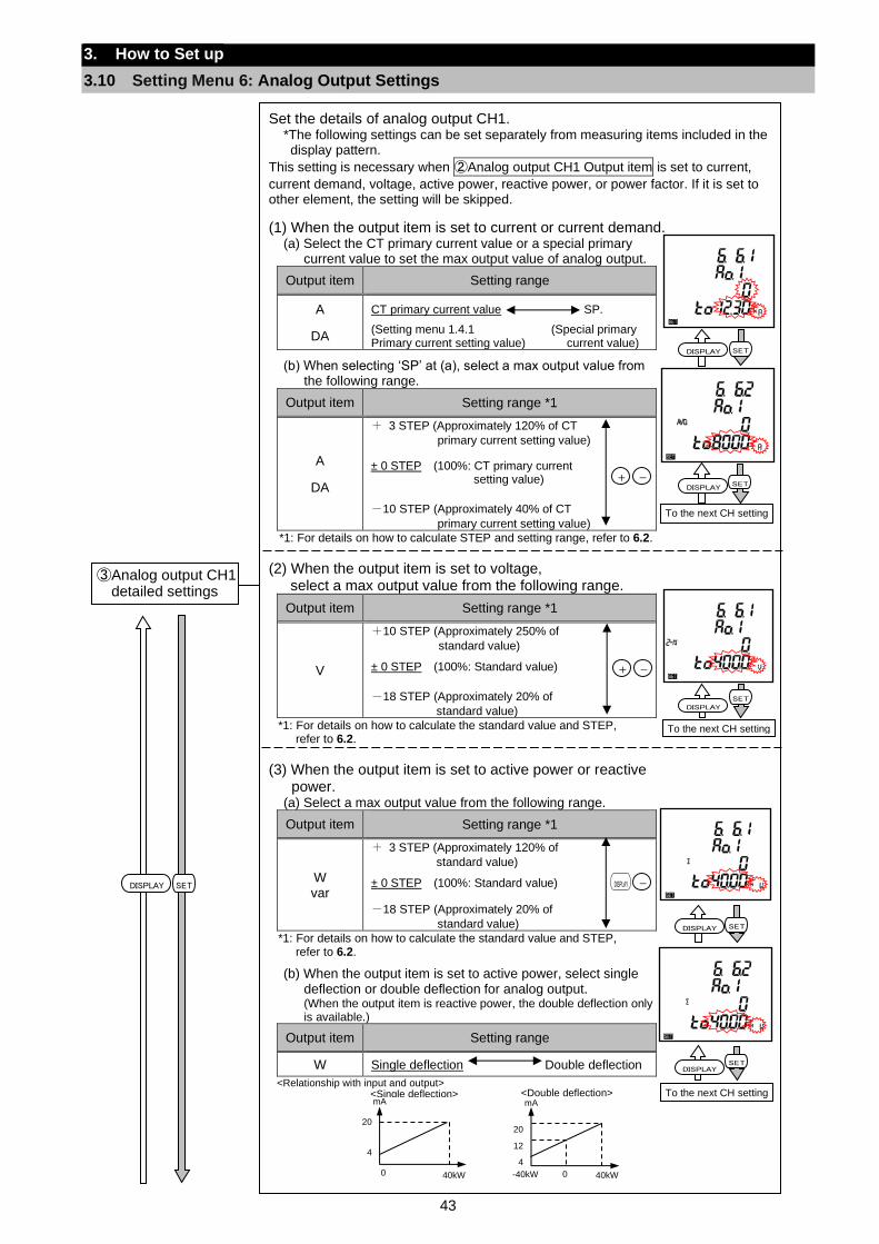
43
3. How to Set up
3.10 Setting Menu 6: Analog Output Settings
Set the details of analog output CH1. *The following settings can be set separately from measuring items included in the display pattern.
This setting is necessary when ②Analog output CH1 Output item is set to current,
current demand, voltage, active power, reactive power, or power factor. If it is set to other element, the setting will be skipped.
(1) When the output item is set to current or current demand. (a) Select the CT primary current value or a special primary
current value to set the max output value of analog output.
Output item Setting range
A
DA
CT primary current value SP.
(Setting menu 1.4.1 (Special primary Primary current setting value) current value)
(b) When selecting ‘SP’ at (a), select a max output value from
the following range.
Output item Setting range *1
A
DA
+ 3 STEP (Approximately 120% of CT
primary current setting value)
± 0 STEP (100%: CT primary current setting value)
-10 STEP (Approximately 40% of CT
primary current setting value)
*1: For details on how to calculate STEP and setting range, refer to 6.2.
(2) When the output item is set to voltage, select a max output value from the following range.
Output item Setting range *1
V
+10 STEP (Approximately 250% of
standard value)
± 0 STEP (100%: Standard value)
-18 STEP (Approximately 20% of
standard value)
*1: For details on how to calculate the standard value and STEP, refer to 6.2.
(3) When the output item is set to active power or reactive power.
(a) Select a max output value from the following range.
Output item Setting range *1
W var
+ 3 STEP (Approximately 120% of
standard value)
± 0 STEP (100%: Standard value)
-18 STEP (Approximately 20% of
standard value)
*1: For details on how to calculate the standard value and STEP, refer to 6.2.
(b) When the output item is set to active power, select single
deflection or double deflection for analog output. (When the output item is reactive power, the double deflection only is available.)
Output item Setting range
W Single deflection Double deflection
<Relationship with input and output>
③Analog output CH1 detailed settings
SETDISPLAY
To the next CH setting
SETDISPLAY
To the next CH setting
SETDISPLAY
SETDISPLAY
SET
To the next CH setting
+ -
DISPLAY -
+ -
mA
4
12
20
-40kW 40kW 0
<Double deflection> mA
4
20
40kW 0
<Single deflection>
SETDISPLAY
DISPLAY
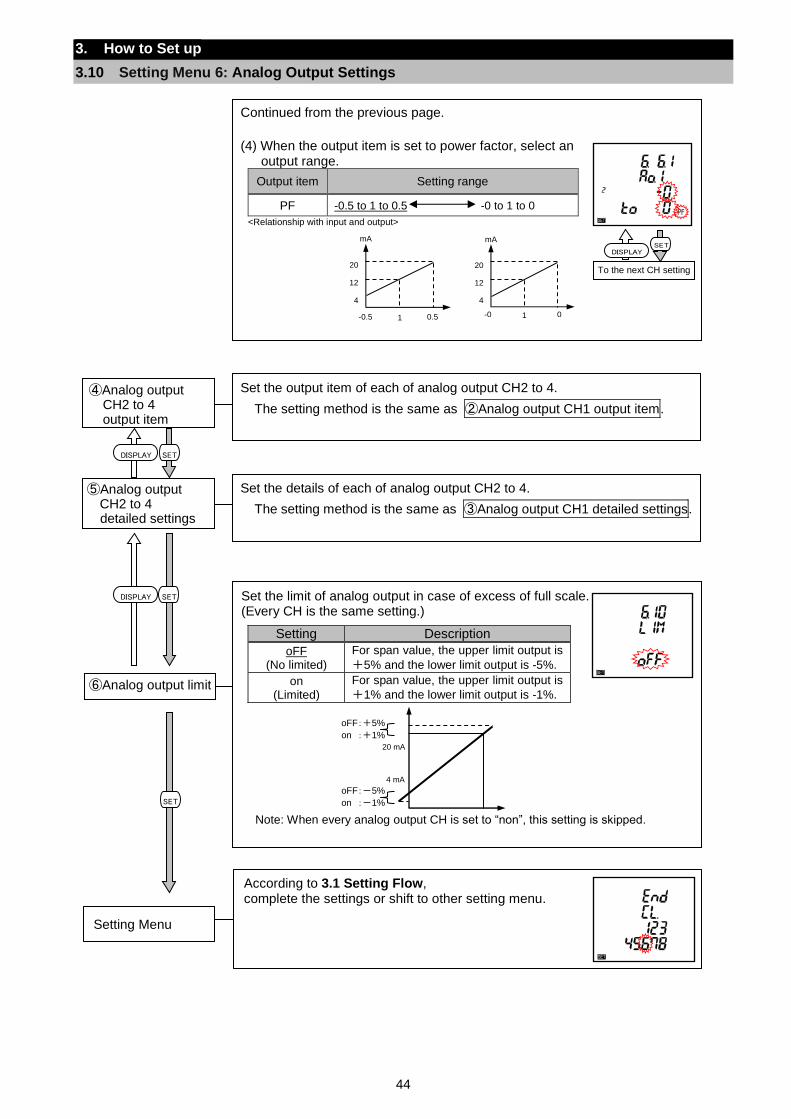
44
3. How to Set up
3.10 Setting Menu 6: Analog Output Settings
Continued from the previous page.
(4) When the output item is set to power factor, select an output range.
Output item Setting range
PF -0.5 to 1 to 0.5 -0 to 1 to 0
<Relationship with input and output>
次のページへ
To the next CH setting
SETmA
4
12
20
-0.5 0.5 1
mA
4
12
20
-0 0 1
Set the output item of each of analog output CH2 to 4.
The setting method is the same as ②Analog output CH1 output item.
④Analog output CH2 to 4 output item
Set the details of each of analog output CH2 to 4.
The setting method is the same as ③Analog output CH1 detailed settings.
⑤Analog output CH2 to 4 detailed settings
Set the limit of analog output in case of excess of full scale. (Every CH is the same setting.)
Setting Description
oFF (No limited)
For span value, the upper limit output is
+5% and the lower limit output is -5%.
on (Limited)
For span value, the upper limit output is
+1% and the lower limit output is -1%.
Note: When every analog output CH is set to “non”, this setting is skipped.
⑥Analog output limit
20 mA
oFF:+5%
on :+1%
oFF:-5%
on :-1%
4 mA
SETDISPLAY
According to 3.1 Setting Flow, complete the settings or shift to other setting menu.
Setting Menu
SET
SETDISPLAY
DISPLAY
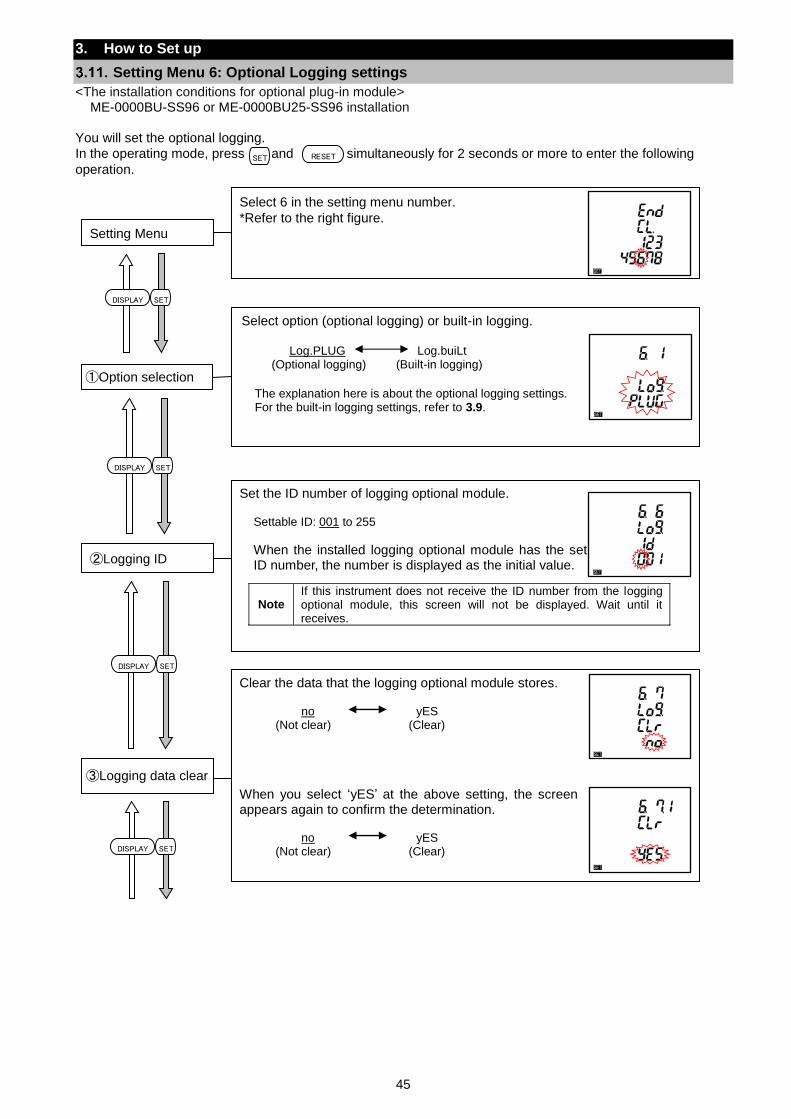
45
3. How to Set up
Setting Menu 6: Optional Logging settings
<The installation conditions for optional plug-in module> ME-0000BU-SS96 or ME-0000BU25-SS96 installation
You will set the optional logging.
In the operating mode, press and simultaneously for 2 seconds or more to enter the following
operation.
Select 6 in the setting menu number.
*Refer to the right figure.
Setting Menu
Select option (optional logging) or built-in logging.
Log.PLUG Log.buiLt (Optional logging) (Built-in logging)
The explanation here is about the optional logging settings. For the built-in logging settings, refer to 3.9.
①Option selection
SETDISPLAY
Set the ID number of logging optional module.
Settable ID: 001 to 255
When the installed logging optional module has the set ID number, the number is displayed as the initial value.
Note If this instrument does not receive the ID number from the logging optional module, this screen will not be displayed. Wait until it receives.
②Logging ID
Clear the data that the logging optional module stores.
no yES (Not clear) (Clear)
When you select ‘yES’ at the above setting, the screen appears again to confirm the determination.
no yES (Not clear) (Clear)
③Logging data clear
SETDISPLAY
SET RESET
SETDISPLAY
SETDISPLAY
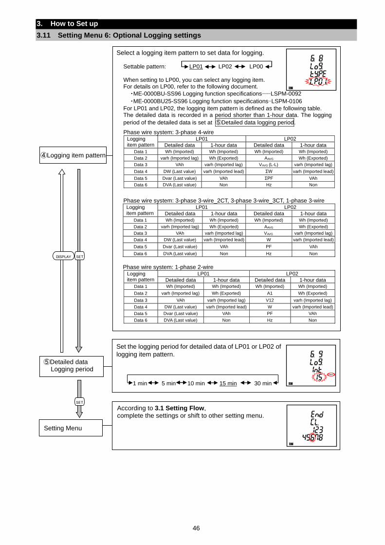
46
3. How to Set up
3.11 Setting Menu 6: Optional Logging settings
Select a logging item pattern to set data for logging.
Settable pattern: LP01 LP02 LP00 When setting to LP00, you can select any logging item. For details on LP00, refer to the following document.
・ME-0000BU-SS96 Logging function specificationsLSPM-0092
・ME-0000BU25-SS96 Logging function specificationsLSPM-0106
For LP01 and LP02, the logging item pattern is defined as the following table. The detailed data is recorded in a period shorter than 1-hour data. The logging
period of the detailed data is set at ⑤Detailed data logging period.
Phase wire system: 3-phase 4-wire Logging item pattern
LP01 LP02
Detailed data 1-hour data Detailed data 1-hour data
Data 1 Wh (Imported) Wh (Imported) Wh (Imported) Wh (Imported)
Data 2 varh (Imported lag) Wh (Exported) AAVG Wh (Exported)
Data 3 VAh varh (Imported lag) VAVG (L-L) varh (Imported lag)
Data 4 DW (Last value) varh (Imported lead) ΣW varh (Imported lead)
Data 5 Dvar (Last value) VAh ΣPF VAh
Data 6 DVA (Last value) Non Hz Non
Phase wire system: 3-phase 3-wire_2CT, 3-phase 3-wire_3CT, 1-phase 3-wire Logging item pattern
LP01 LP02
Detailed data 1-hour data Detailed data 1-hour data
Data 1 Wh (Imported) Wh (Imported) Wh (Imported) Wh (Imported)
Data 2 varh (Imported lag) Wh (Exported) AAVG Wh (Exported)
Data 3 VAh varh (Imported lag) VAVG varh (Imported lag)
Data 4 DW (Last value) varh (Imported lead) W varh (Imported lead)
Data 5 Dvar (Last value) VAh PF VAh
Data 6 DVA (Last value) Non Hz Non
Phase wire system: 1-phase 2-wire
Logging item pattern
LP01 LP02
Detailed data 1-hour data Detailed data 1-hour data
Data 1 Wh (Imported) Wh (Imported) Wh (Imported) Wh (Imported)
Data 2 varh (Imported lag) Wh (Exported) A1 Wh (Exported)
Data 3 VAh varh (Imported lag) V12 varh (Imported lag)
Data 4 DW (Last value) varh (Imported lead) W varh (Imported lead)
Data 5 Dvar (Last value) VAh PF VAh
Data 6 DVA (Last value) Non Hz Non
④Logging item pattern
SETDISPLAY
Set the logging period for detailed data of LP01 or LP02 of
logging item pattern.
1 min 5 min 10 min 15 min 30 min
⑤Detailed data Logging period
SET
According to 3.1 Setting Flow, complete the settings or shift to other setting menu.
Setting Menu
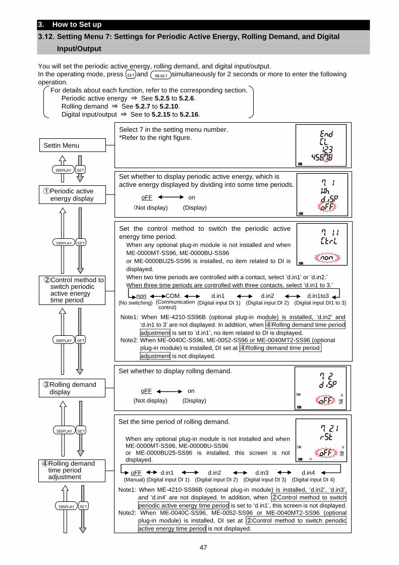
47
3. How to Set up
Setting Menu 7: Settings for Periodic Active Energy, Rolling Demand, and Digital
Input/Output
You will set the periodic active energy, rolling demand, and digital input/output.
In the operating mode, press and simultaneously for 2 seconds or more to enter the following
operation.
For details about each function, refer to the corresponding section.
Periodic active energy ⇒ See 5.2.5 to 5.2.6.
Rolling demand ⇒ See 5.2.7 to 5.2.10.
Digital input/output ⇒ See to 5.2.15 to 5.2.16.
SET RESET
Select 7 in the setting menu number.
*Refer to the right figure.
Settin Menu
Set whether to display periodic active energy, which is
active energy displayed by dividing into some time periods. oFF on
(Not display) (Display)
①Periodic active energy display
Set whether to display rolling demand.
oFF on
(Not display) (Display)
③Rolling demand display
Set the control method to switch the periodic active
energy time period.
When any optional plug-in module is not installed and when
ME-0000MT-SS96, ME-0000BU-SS96
or ME-0000BU25-SS96 is installed, no item related to DI is
displayed.
When two time periods are controlled with a contact, select ‘d.in1’ or ‘d.in2.’
When three time periods are controlled with three contacts, select ‘d.in1 to 3.’
②Control method to switch periodic active energy time period
Note1: When ME-4210-SS96B (optional plug-in module) is installed, ‘d.in2’ and
‘d.in1 to 3’ are not displayed. In addition, when ④Rolling demand time period
adjustment is set to ‘d.in1’, no item related to DI is displayed.
Note2: When ME-0040C-SS96, ME-0052-SS96 or ME-0040MT2-SS96 (optional
plug-in module) is installed, DI set at ④Rolling demand time period
adjustment is not displayed.
(No switching) ( (Digital input DI 1) (Digital input DI 2) (Digital input DI1 to 3)
non COM. d.in1 d.in2 d.in1to3 (Communication control)
Set the time period of rolling demand.
When any optional plug-in module is not installed and when ME-0000MT-SS96, ME-0000BU-SS96 or ME-0000BU25-SS96 is installed, this screen is not displayed.
④Rolling demand time period adjustment (Manual) (Digital input DI 1) (Digital input DI 2) (Digital input DI 3) (Digital input DI 4)
oFF d.in1 d.in2 d.in3 d.in4
Note1: When ME-4210-SS96B (optional plug-in module) is installed, ‘d.in2’, ‘d.in3’,
and ‘d.in4’ are not displayed. In addition, when ②Control method to switch
periodic active energy time period is set to ‘d.in1’, this screen is not displayed.
Note2: When ME-0040C-SS96, ME-0052-SS96 or ME-0040MT2-SS96 (optional
plug-in module) is installed, DI set at ②Control method to switch periodic
active energy time period is not displayed.
SETDISPLAY
SETDISPLAY
SETDISPLAY
SETDISPLAY
SETDISPLAY
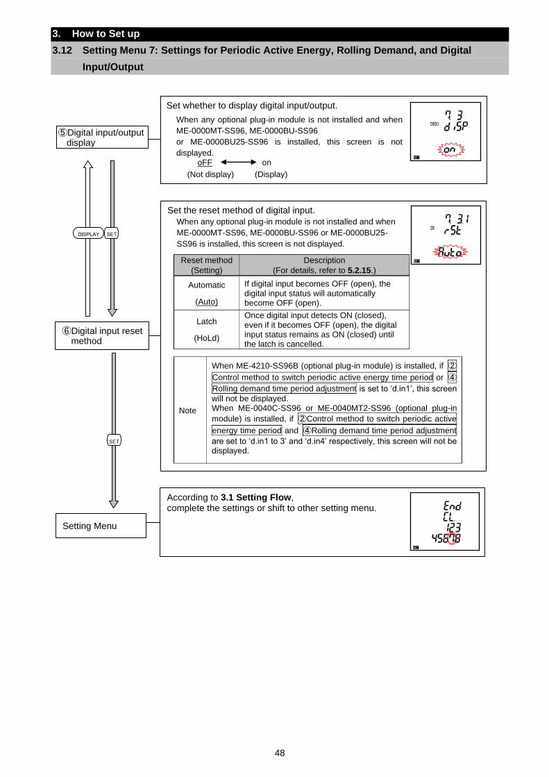
48
3. How to Set up
3.12 Setting Menu 7: Settings for Periodic Active Energy, Rolling Demand, and Digital
Input/Output
Set whether to display digital input/output.
When any optional plug-in module is not installed and when
ME-0000MT-SS96, ME-0000BU-SS96
or ME-0000BU25-SS96 is installed, this screen is not
displayed.
oFF on
(Not display) (Display)
⑤Digital input/output display
Set the reset method of digital input.
When any optional plug-in module is not installed and when
ME-0000MT-SS96, ME-0000BU-SS96 or ME-0000BU25-
SS96 is installed, this screen is not displayed.
Reset method
(Setting)
Description
(For details, refer to 5.2.15.)
Automatic
(Auto)
If digital input becomes OFF (open), the digital input status will automatically become OFF (open).
Latch
(HoLd)
Once digital input detects ON (closed), even if it becomes OFF (open), the digital input status remains as ON (closed) until the latch is cancelled.
Note
When ME-4210-SS96B (optional plug-in module) is installed, if ②
Control method to switch periodic active energy time period or ④
Rolling demand time period adjustment is set to ‘d.in1’, this screen
will not be displayed. When ME-0040C-SS96 or ME-0040MT2-SS96 (optional plug-in
module) is installed, if ②Control method to switch periodic active
energy time period and ④Rolling demand time period adjustment
are set to ‘d.in1 to 3’ and ‘d.in4’ respectively, this screen will not be displayed.
⑥Digital input reset method
SET
According to 3.1 Setting Flow, complete the settings or shift to other setting menu.
Setting Menu
SETDISPLAY
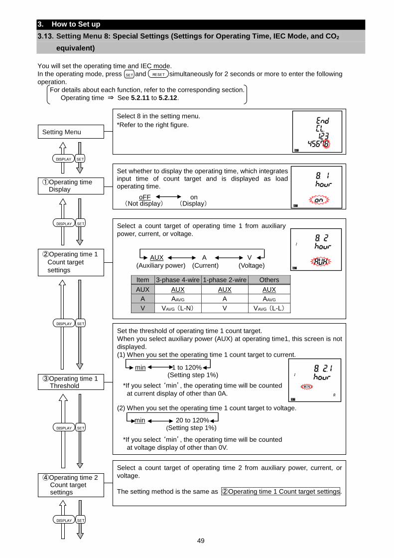
49
Set the threshold of operating time 1 count target.
When you select auxiliary power (AUX) at operating time1, this screen is not
displayed. (1) When you set the operating time 1 count target to current.
*If you select ‘min’, the operating time will be counted
at current display of other than 0A.
(2) When you set the operating time 1 count target to voltage.
*If you select ‘min’, the operating time will be counted
at voltage display of other than 0V.
③Operating time 1 Threshold
min 1 to 120% (Setting step 1%)
min 20 to 120% (Setting step 1%)
Select a count target of operating time 1 from auxiliary
power, current, or voltage.
Item 3-phase 4-wire 1-phase 2-wire Others
AUX AUX AUX AUX
A AAVG A AAVG
V VAVG (L-N) V VAVG (L-L)
②Operating time 1
Count target
settings (Auxiliary power) (Current) (Voltage)
AUX A V
3. How to Set up
Setting Menu 8: Special Settings (Settings for Operating Time, IEC Mode, and CO2
equivalent)
You will set the operating time and IEC mode.
In the operating mode, press and simultaneously for 2 seconds or more to enter the following
operation.
For details about each function, refer to the corresponding section.
Operating time ⇒ See 5.2.11 to 5.2.12.
SETDISPLAY
SETDISPLAY
SETDISPLAY
SET RESET
Select 8 in the setting menu.
*Refer to the right figure. Setting Menu
Set whether to display the operating time, which integrates input time of count target and is displayed as load operating time.
①Operating time Display
oFF on (Not display) (Display)
Select a count target of operating time 2 from auxiliary power, current, or
voltage.
The setting method is the same as ②Operating time 1 Count target settings.
④Operating time 2 Count target settings
SETDISPLAY
SETDISPLAY
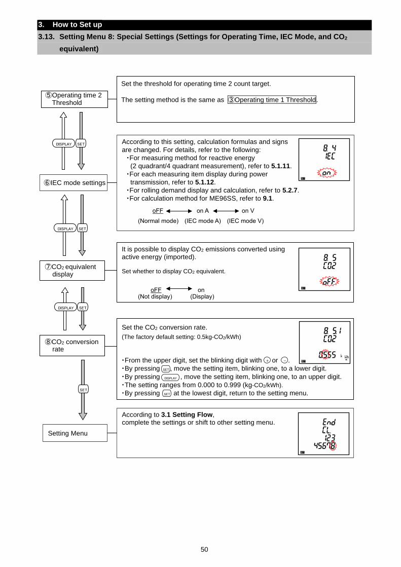
50
3. How to Set up
3.13. Setting Menu 8: Special Settings (Settings for Operating Time, IEC Mode, and CO2
equivalent)
Set the CO2 conversion rate.
(The factory default setting: 0.5kg-CO2/kWh)
・From the upper digit, set the blinking digit with or .
・By pressing , move the setting item, blinking one, to a lower digit.
・By pressing , move the setting item, blinking one, to an upper digit.
・The setting ranges from 0.000 to 0.999 (kg-CO2/kWh).
・By pressing at the lowest digit, return to the setting menu.
⑧CO2 conversion rate
According to this setting, calculation formulas and signs
are changed. For details, refer to the following:
・For measuring method for reactive energy
(2 quadrant/4 quadrant measurement), refer to 5.1.11.
・For each measuring item display during power
transmission, refer to 5.1.12.
・For rolling demand display and calculation, refer to 5.2.7.
・For calculation method for ME96SS, refer to 9.1.
⑥IEC mode settings
According to 3.1 Setting Flow, complete the settings or shift to other setting menu.
Setting Menu
SETDISPLAY
It is possible to display CO2 emissions converted using active energy (imported). Set whether to display CO2 equivalent.
oFF on
(Not display) (Display)
⑦CO2 equivalent display
SETDISPLAY
SETDISPLAY
SET
DISPLAY
SET
+ -
Set the threshold for operating time 2 count target.
The setting method is the same as ③Operating time 1 Threshold.
⑤Operating time 2 Threshold
oFF on A on V
(Normal mode) (IEC mode A) (IEC mode V)
SET
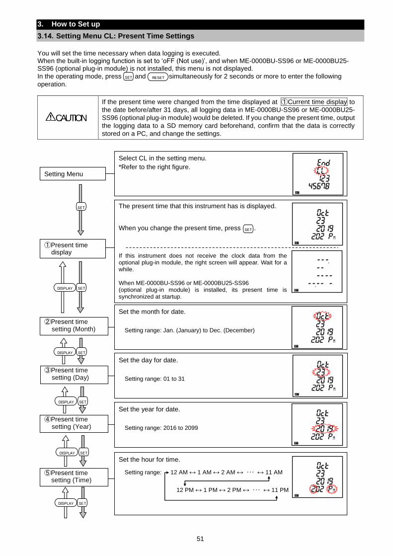
51
The present time that this instrument has is displayed.
When you change the present time, press . If this instrument does not receive the clock data from the optional plug-in module, the right screen will appear. Wait for a while. When ME-0000BU-SS96 or ME-0000BU25-SS96 (optional plug-in module) is installed, its present time is synchronized at startup.
①Present time display
SET
3. How to Set up
Setting Menu CL: Present Time Settings
You will set the time necessary when data logging is executed. When the built-in logging function is set to ‘oFF (Not use)’, and when ME-0000BU-SS96 or ME-0000BU25-SS96 (optional plug-in module) is not installed, this menu is not displayed.
In the operating mode, press and simultaneously for 2 seconds or more to enter the following
operation.
CAUTION
If the present time were changed from the time displayed at ①Current time display to
the date before/after 31 days, all logging data in ME-0000BU-SS96 or ME-0000BU25-
SS96 (optional plug-in module) would be deleted. If you change the present time, output
the logging data to a SD memory card beforehand, confirm that the data is correctly
stored on a PC, and change the settings.
SET RESET
Select CL in the setting menu.
*Refer to the right figure.
Setting Menu
Set the month for date.
Setting range: Jan. (January) to Dec. (December)
②Present time setting (Month)
Set the day for date.
Setting range: 01 to 31
③Present time setting (Day)
Set the year for date.
Setting range: 2016 to 2099
④Present time setting (Year)
Set the hour for time.
Setting range: 12 AM ↔ 1 AM ↔ 2 AM ↔ ・・・ ↔ 11 AM
12 PM ↔ 1 PM ↔ 2 PM ↔ ・・・ ↔ 11 PM
⑤Present time setting (Time)
SETDISPLAY
SET
SETDISPLAY
SETDISPLAY
SETDISPLAY
SETDISPLAY
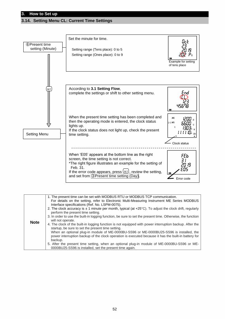
52
3. How to Set up
3.14. Setting Menu CL: Current Time Settings
Note
1. The present time can be set with MODBUS RTU or MODBUS TCP communication. For details on the setting, refer to Electronic Multi-Measuring Instrument ME Series MODBUS Interface specifications (Ref. No. LSPM-0075).
2. The clock accuracy is ± 1 minute per month, typical (at +25°C). To adjust the clock drift, regularly perform the present time setting.
3. In order to use the built-in logging function, be sure to set the present time. Otherwise, the function will not operate.
4. The clock of the built-in logging function is not equipped with power interruption backup. After the startup, be sure to set the present time setting. When an optional plug-in module of ME-0000BU-SS96 or ME-0000BU25-SS96 is installed, the power interruption backup of the clock operation is executed because it has the built-in battery for backup.
5. After the present time setting, when an optional plug-in module of ME-0000BU-SS96 or ME-0000BU25-SS96 is installed, set the present time again.
According to 3.1 Setting Flow, complete the settings or shift to other setting menu.
When the present time setting has been completed and then the operating mode is entered, the clock status lights up. If the clock status does not light up, check the present time setting.
When ‘E05’ appears at the bottom line as the right screen, the time setting is not correct. *The right figure illustrates an example for the setting of Feb. 31.
If the error code appears, press , review the setting, and set from ③Present time setting (Day).
Setting Menu
SET
Set the minute for time.
Setting range (Tens place): 0 to 5
Setting range (Ones place): 0 to 9
⑥Present time setting (Minute)
Example for setting of tens place
Error code
Clock status
SET
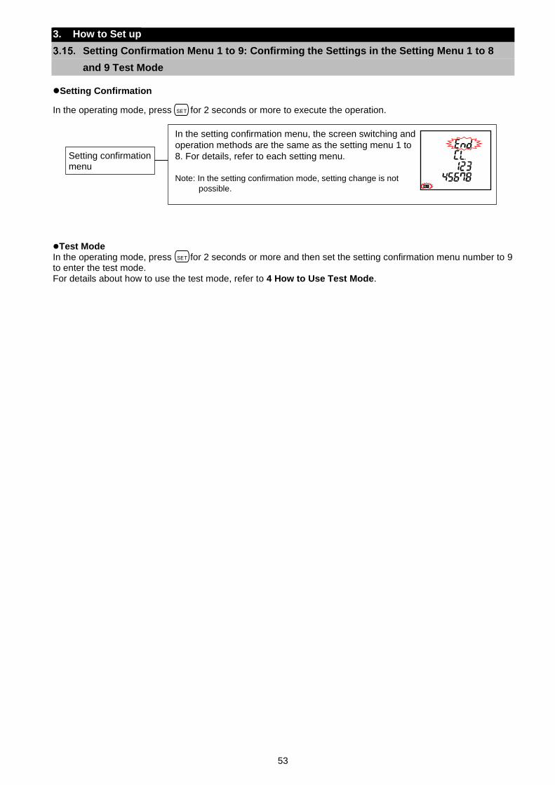
53
3. How to Set up
Setting Confirmation Menu 1 to 9: Confirming the Settings in the Setting Menu 1 to 8
and 9 Test Mode
Setting Confirmation
In the operating mode, press for 2 seconds or more to execute the operation.
Test Mode
In the operating mode, press for 2 seconds or more and then set the setting confirmation menu number to 9 to enter the test mode. For details about how to use the test mode, refer to 4 How to Use Test Mode.
SET
SET
In the setting confirmation menu, the screen switching and
operation methods are the same as the setting menu 1 to
8. For details, refer to each setting menu.
Note: In the setting confirmation mode, setting change is not
possible.
Setting confirmation menu
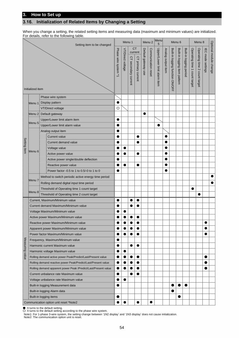
54
3. How to Set up
Initialization of Related Items by Changing a Setting
When you change a setting, the related setting items and measuring data (maximum and minimum values) are initialized. For details, refer to the following table.
Setting item to be changed
Initialized item
Menu 1 Menu 2 Menu
5 Menu 6 Menu 8
Op
tion
al m
od
ule
cha
ng
e
Ph
ase
wire
syste
m *1
VT
/Dire
ct v
olta
ge
CT current
De
fau
lt gate
way u
se
Co
mm
un
ica
tion
rese
t
Up
pe
r/Lo
we
r limit a
larm
item
An
alo
g o
utp
ut ite
m
Built-in
log
gin
g fu
nctio
n O
N/O
FF
Built-in
log
gin
g ite
m p
atte
rn
Built-in
log
gin
g p
erio
d
Op
era
ting
time 1
co
unt ta
rge
t
Op
era
ting
time 2
co
unt ta
rge
t
IEC
mo
de s
ettin
gs
CT
secon
da
ry c
urre
nt
CT
prim
ary
cu
rrent
Se
tting ite
m
Menu 1
Phase wire system
Display pattern
VT/Direct voltage
Menu 2 Default gateway
Menu 5 Upper/Lower limit alarm item
Upper/Lower limit alarm value
Menu 6
Analog output item
Current value
Current demand value
Voltage value
Active power value
Active power single/double deflection
Reactive power value
Power factor -0.5 to 1 to 0.5/-0 to 1 to 0
Menu 7 Method to switch periodic active energy time period
Rolling demand digital input time period
Menu 8 Threshold of Operating time 1 count target
Threshold of Operating time 2 count target
Me
asurin
g v
alu
e
Current, Maximum/Minimum value
Current demand Maximum/Minimum value
Voltage Maximum/Minimum value
Active power Maximum/Minimum value
Reactive power Maximum/Minimum value
Apparent power Maximum/Minimum value
Power factor Maximum/Minimum value
Frequency, Maximum/Minimum value
Harmonic current Maximum value
Harmonic voltage Maximum value
Rolling demand active power Peak/Predict/Last/Present value
Rolling demand reactive power Peak/Predict/Last/Present value
Rolling demand apparent power Peak /Predict/Last/Present value
Current unbalance rate Maximum value
Voltage unbalance rate Maximum value
Built-in logging Measurement data
Built-in logging Alarm data
Built-in logging items
Communication option unit reset *Note2
: It turns to the default setting. : It turns to the default setting according to the phase wire system.
Note1: For 1-phase 3-wire system, the setting change between ‘1N2 display’ and ‘1N3 display’ does not cause initialization. Note2: The communication option unit is reset.
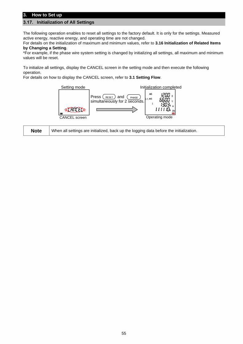
55
3. How to Set up
Initialization of All Settings
The following operation enables to reset all settings to the factory default. It is only for the settings. Measured
active energy, reactive energy, and operating time are not changed.
For details on the initialization of maximum and minimum values, refer to 3.16 Initialization of Related Items
by Changing a Setting.
*For example, if the phase wire system setting is changed by initializing all settings, all maximum and minimum
values will be reset.
To initialize all settings, display the CANCEL screen in the setting mode and then execute the following
operation.
For details on how to display the CANCEL screen, refer to 3.1 Setting Flow.
Setting mode Initialization completed
Press and
simultaneously for 2 seconds.
Note When all settings are initialized, back up the logging data before the initialization.
RESET PHASE
CANCEL screen Operating mode
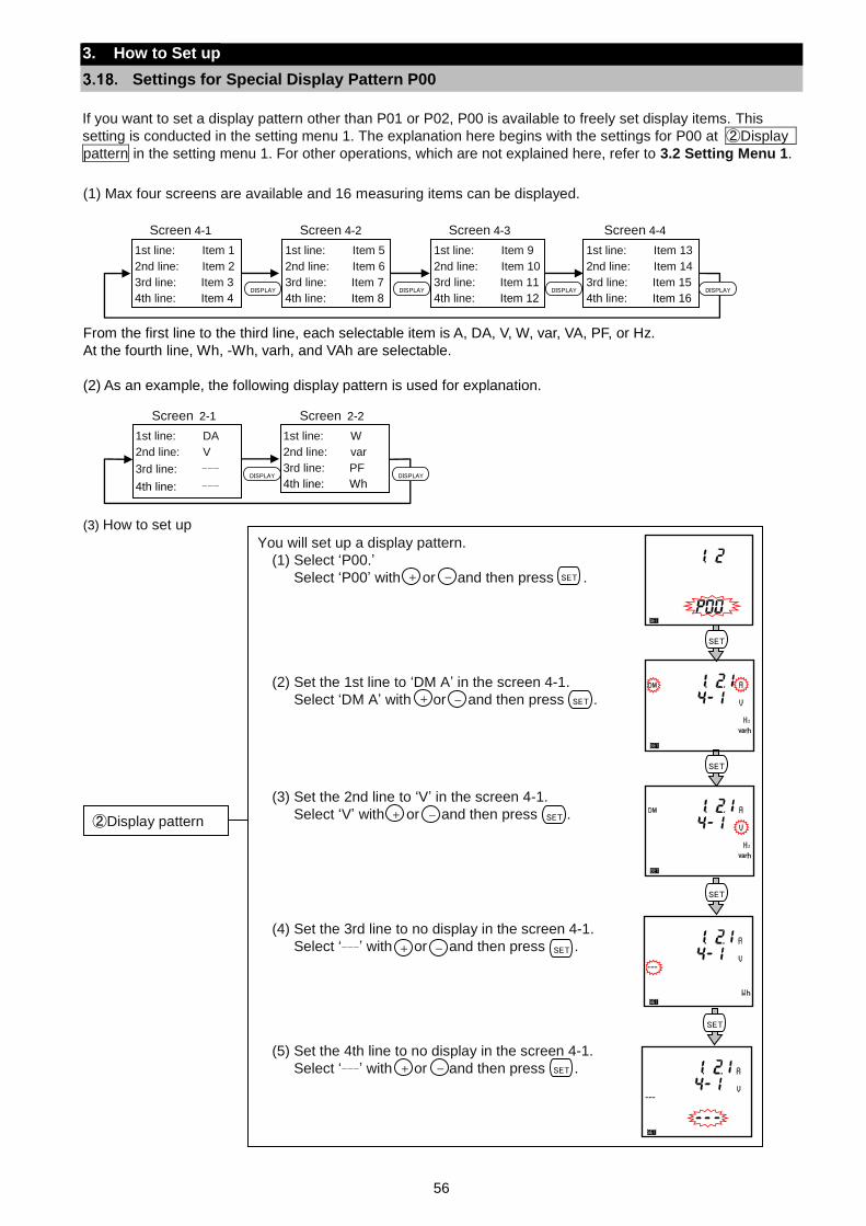
56
3. How to Set up
Settings for Special Display Pattern P00
If you want to set a display pattern other than P01 or P02, P00 is available to freely set display items. This
setting is conducted in the setting menu 1. The explanation here begins with the settings for P00 at ②Display
pattern in the setting menu 1. For other operations, which are not explained here, refer to 3.2 Setting Menu 1.
(1) Max four screens are available and 16 measuring items can be displayed.
From the first line to the third line, each selectable item is A, DA, V, W, var, VA, PF, or Hz.
At the fourth line, Wh, -Wh, varh, and VAh are selectable.
(2) As an example, the following display pattern is used for explanation.
(3) How to set up
DISPLAY
1st line: Item 1
2nd line: Item 2
3rd line: Item 3
4th line: Item 4
1st line: Item 5
2nd line: Item 6
3rd line: Item 7
4th line: Item 8
1st line: Item 9
2nd line: Item 10
3rd line: Item 11
4th line: Item 12
1st line: Item 13
2nd line: Item 14
3rd line: Item 15
4th line: Item 16
DISPLAY DISPLAY DISPLAY
Screen 4-1 Screen 4-4 Screen 4-3 Screen 4-2
DISPLAY
1st line: DA
2nd line: V
3rd line: ---
4th line: ---
Lower stage: Wh
1st line: W
2nd line: var
3rd line: PF
4th line: Wh
DISPLAY
Screen 2-1 Screen 2-2
You will set up a display pattern.
(1) Select ‘P00.’
Select ‘P00’ with or and then press .
(2) Set the 1st line to ‘DM A’ in the screen 4-1.
Select ‘DM A’ with or and then press .
(3) Set the 2nd line to ‘V’ in the screen 4-1.
Select ‘V’ with or and then press .
(4) Set the 3rd line to no display in the screen 4-1.
Select ‘---’ with or and then press .
(5) Set the 4th line to no display in the screen 4-1.
Select ‘---’ with or and then press .
②Display pattern
+ - SET
SET
SET
SET
SET
+ - SET
+ - SET
+ - SET
+ - SET
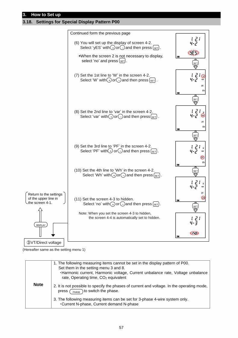
57
3. How to Set up
3.18. Settings for Special Display Pattern P00
(Hereafter same as the setting menu 1)
Note
1. The following measuring items cannot be set in the display pattern of P00.
Set them in the setting menu 3 and 8.
・Harmonic current, Harmonic voltage, Current unbalance rate, Voltage unbalance
rate, Operating time, CO2 equivalent
2. It is not possible to specify the phases of current and voltage. In the operating mode,
press to switch the phase.
3. The following measuring items can be set for 3-phase 4-wire system only.
・Current N-phase, Current demand N-phase
③VT/Direct voltage
DISPLAY
Return to the settings of the upper line in
the screen 4-1.
PHASE
Continued form the previous page
(6) You will set up the display of screen 4-2.
Select ‘yES’ with or and then press .
*When the screen 2 is not necessary to display,
select ‘no’ and press .
(7) Set the 1st line to ‘W’ in the screen 4-2.
Select ‘W’ with or and then press .
(8) Set the 2nd line to ‘var’ in the screen 4-2.
Select ‘var’ with or and then press .
(9) Set the 3rd line to ‘PF’ in the screen 4-2.
Select ‘PF’ with or and then press .
(10) Set the 4th line to ‘Wh’ in the screen 4-2.
Select ‘Wh’ with or and then press .
(11) Set the screen 4-3 to hidden.
Select ‘no’ with or and then press .
Note: When you set the screen 4-3 to hidden,
the screen 4-4 is automatically set to hidden.
+ - SET
+ - SET
+ - SET
+ - SET
+ - SET
SET
SET
SET
SET
SET
SET
+ - SET
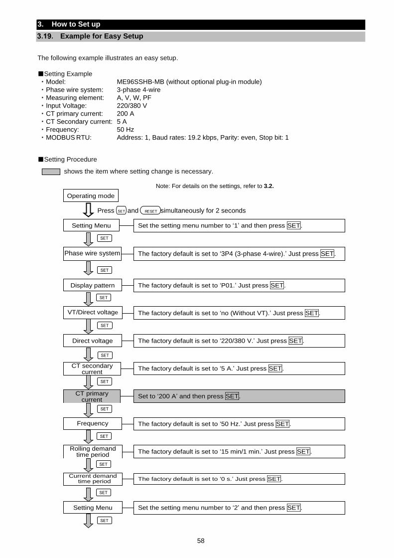
58
3. How to Set up
Example for Easy Setup
The following example illustrates an easy setup.
Setting Example
・ Model: ME96SSHB-MB (without optional plug-in module)
・ Phase wire system: 3-phase 4-wire
・ Measuring element: A, V, W, PF
・ Input Voltage: 220/380 V
・ CT primary current: 200 A
・ CT Secondary current: 5 A
・ Frequency: 50 Hz
・ MODBUS RTU: Address: 1, Baud rates: 19.2 kbps, Parity: even, Stop bit: 1
Setting Procedure
shows the item where setting change is necessary.
Operating mode
Set the setting menu number to ‘1’ and then press SET. Setting Menu
The factory default is set to ‘3P4 (3-phase 4-wire).’ Just press SET. Phase wire system
The factory default is set to ‘P01.’ Just press SET. Display pattern
The factory default is set to ‘no (Without VT).’ Just press SET. VT/Direct voltage
The factory default is set to ‘220/380 V.’ Just press SET. Direct voltage
The factory default is set to ‘5 A.’ Just press SET. CT secondary current
Set to ‘200 A’ and then press SET. CT primary current
The factory default is set to ‘50 Hz.’ Just press SET. Frequency
The factory default is set to ‘15 min/1 min.’ Just press SET. Rolling demand
time period
The factory default is set to ‘0 s.’ Just press SET.
Current demand time period
Set the setting menu number to ‘2’ and then press SET. Setting Menu
SET
Note: For details on the settings, refer to 3.2.
SET
SET
SET
SET
SET
SET
SET
SET
Press and simultaneously for 2 seconds RESETSET
SET
SET
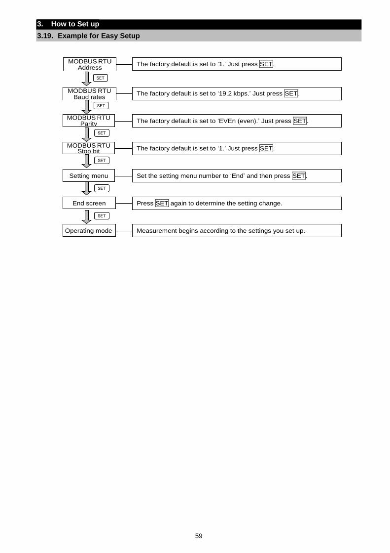
59
3. How to Set up
3.19. Example for Easy Setup
The factory default is set to ‘1.’ Just press SET. MODBUS RTU Address
The factory default is set to ‘19.2 kbps.’ Just press SET. MODBUS RTU Baud rates
The factory default is set to ‘EVEn (even).’ Just press SET. MODBUS RTU
Parity
The factory default is set to ‘1.’ Just press SET. MODBUS RTU Stop bit
Set the setting menu number to ‘End’ and then press SET. Setting menu
Press SET again to determine the setting change. End screen
Measurement begins according to the settings you set up. Operating mode
SET
SET
SET
SET
SET
SET
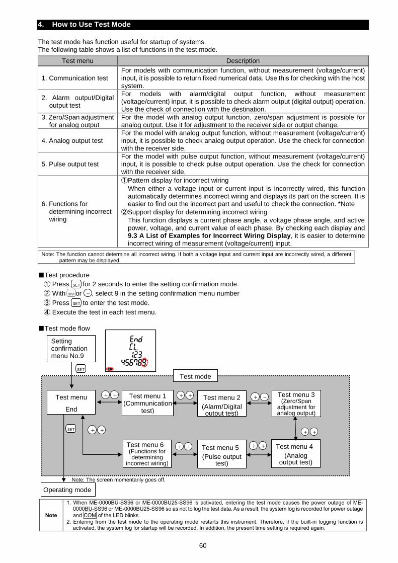
60
4. How to Use Test Mode
The test mode has function useful for startup of systems. The following table shows a list of functions in the test mode.
Test menu Description
1. Communication test For models with communication function, without measurement (voltage/current) input, it is possible to return fixed numerical data. Use this for checking with the host system.
2. Alarm output/Digital output test
For models with alarm/digital output function, without measurement (voltage/current) input, it is possible to check alarm output (digital output) operation. Use the check of connection with the destination.
3. Zero/Span adjustment for analog output
For the model with analog output function, zero/span adjustment is possible for analog output. Use it for adjustment to the receiver side or output change.
4. Analog output test For the model with analog output function, without measurement (voltage/current) input, it is possible to check analog output operation. Use the check for connection with the receiver side.
5. Pulse output test For the model with pulse output function, without measurement (voltage/current) input, it is possible to check pulse output operation. Use the check for connection with the receiver side.
6. Functions for determining incorrect wiring
①Pattern display for incorrect wiring
When either a voltage input or current input is incorrectly wired, this function automatically determines incorrect wiring and displays its part on the screen. It is easier to find out the incorrect part and useful to check the connection. *Note
②Support display for determining incorrect wiring
This function displays a current phase angle, a voltage phase angle, and active power, voltage, and current value of each phase. By checking each display and 9.3 A List of Examples for Incorrect Wiring Display, it is easier to determine incorrect wiring of measurement (voltage/current) input.
Note: The function cannot determine all incorrect wiring. If both a voltage input and current input are incorrectly wired, a different
pattern may be displayed.
Test procedure
① Press for 2 seconds to enter the setting confirmation mode.
② With or , select 9 in the setting confirmation menu number
③ Press to enter the test mode.
④ Execute the test in each test menu.
Test mode flow
Note
1. When ME-0000BU-SS96 or ME-0000BU25-SS96 is activated, entering the test mode causes the power outage of ME-0000BU-SS96 or ME-0000BU25-SS96 so as not to log the test data. As a result, the system log is recorded for power outage
and COM of the LED blinks.
2. Entering from the test mode to the operating mode restarts this instrument. Therefore, if the built-in logging function is activated, the system log for startup will be recorded. In addition, the present time setting is required again.
Test menu 6 (Functions for determining
incorrect wiring)
Operating mode
Test mode
+ +
+ ++ +
SET
DISPLAY -
SET
SET
SET
Setting confirmation menu No.9
Test menu
End
Note: The screen momentarily goes off.
Test menu 1 (Communication
test)
+ + Test menu 2
(Alarm/Digital output test)
Test menu 3 (Zero/Span
adjustment for analog output)
+ + Test menu 5
(Pulse output test)
+ + Test menu 4
(Analog output test)
+ -
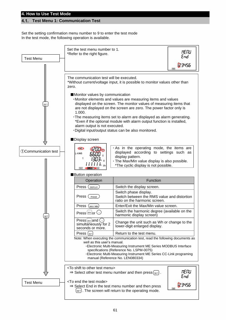
61
4. How to Use Test Mode
Test Menu 1: Communication Test
Set the setting confirmation menu number to 9 to enter the test mode
In the test mode, the following operation is available.
①Communication test
SET
SET
DISPLAY -
PHASE
MAX/MIN
DISPLAY -
The communication test will be executed. *Without current/voltage input, it is possible to monitor values other than zero.
Monitor values by communication
・Monitor elements and values are measuring items and values displayed on the screen. The monitor values of measuring items that are not displayed on the screen are zero. The power factor only is 1.000.
・The measuring items set to alarm are displayed as alarm generating. *Even if the optional module with alarm output function is installed, alarm output is not executed.
・Digital input/output status can be also monitored.
Display screen
・As in the operating mode, the items are displayed according to settings such as display pattern.
・ The Max/Min value display is also possible. *The cyclic display is not possible.
Button operation
Operation Function
Press Switch the display screen.
Press Switch phase display.
Switch between the RMS value and distortion ratio on the harmonic screen.
Press Enter/Exit the Max/Min value screen.
Press or Switch the harmonic degree (available on the harmonic display screen)
Press and simultaneously for 2 seconds or more.
Change the unit such as Wh or change to the lower-digit enlarged display.
Press Return to the test menu.
Note: When executing the communication test, read the following documents as well as this user’s manual. ・Electronic Multi-Measuring Instrument ME Series MODBUS Interface
specifications (Reference No. LSPM-0075) ・Electronic Multi-Measuring Instrument ME Series CC-Link programing
manual (Reference No. LEN080334)
SET
SET
Set the test menu number to 1. *Refer to the right figure.
Test Menu
<To shift to other test menu>
⇒ Select other test menu number and then press .
<To end the test mode>
⇒ Select End in the test menu number and then press .
. The screen will return to the operating mode.
Test Menu
SET
SET
DISPLAY
SET
DISPLAY -
PHASE
MAX/MIN
DISPLAY -
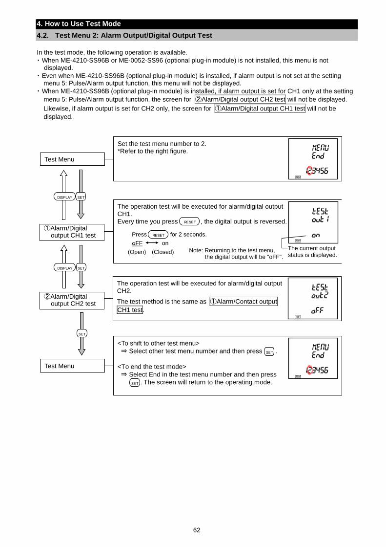
62
4. How to Use Test Mode
Test Menu 2: Alarm Output/Digital Output Test
In the test mode, the following operation is available.
・ When ME-4210-SS96B or ME-0052-SS96 (optional plug-in module) is not installed, this menu is not displayed.
・ Even when ME-4210-SS96B (optional plug-in module) is installed, if alarm output is not set at the setting menu 5: Pulse/Alarm output function, this menu will not be displayed.
・ When ME-4210-SS96B (optional plug-in module) is installed, if alarm output is set for CH1 only at the setting
menu 5: Pulse/Alarm output function, the screen for ②Alarm/Digital output CH2 test will not be displayed.
Likewise, if alarm output is set for CH2 only, the screen for ①Alarm/Digital output CH1 test will not be
displayed.
Set the test menu number to 2. *Refer to the right figure.
Test Menu
The operation test will be executed for alarm/digital output CH1. Every time you press , the digital output is reversed.
①Alarm/Digital output CH1 test
oFF on
(Open) (Closed) Note: Returning to the test menu, the digital output will be "oFF".
RESET
RESETPress for 2 seconds.
The current output status is displayed.
<To shift to other test menu>
⇒ Select other test menu number and then press .
<To end the test mode>
⇒ Select End in the test menu number and then press .
. The screen will return to the operating mode.
Test Menu
SET
SET
SET
SETDISPLAY
The operation test will be executed for alarm/digital output CH2.
The test method is the same as ①Alarm/Contact output
CH1 test.
②Alarm/Digital output CH2 test
SETDISPLAY
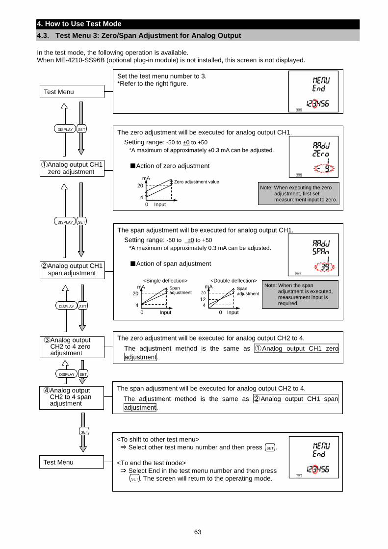
63
4. How to Use Test Mode
Test Menu 3: Zero/Span Adjustment for Analog Output
In the test mode, the following operation is available. When ME-4210-SS96B (optional plug-in module) is not installed, this screen is not displayed.
Set the test menu number to 3. *Refer to the right figure.
Test Menu
The zero adjustment will be executed for analog output CH1.
Setting range: -50 to ±0 to +50
*A maximum of approximately ±0.3 mA can be adjusted.
Action of zero adjustment
①Analog output CH1 zero adjustment
Note: When executing the zero adjustment, first set measurement input to zero.
mA
4
20
Input 0
Zero adjustment value
The span adjustment will be executed for analog output CH1.
Setting range: -50 to ±0 to +50
*A maximum of approximately 0.3 mA can be adjusted.
Action of span adjustment
②Analog output CH1 span adjustment
Note: When the span adjustment is executed, measurement input is required.
mA
4
20
Input 0
<Single deflection>
Span adjustment
mA
4 12
20
Input 0
<Double deflection>
Span adjustment
The zero adjustment will be executed for analog output CH2 to 4.
The adjustment method is the same as ①Analog output CH1 zero
adjustment.
③Analog output CH2 to 4 zero adjustment
The span adjustment will be executed for analog output CH2 to 4.
The adjustment method is the same as ②Analog output CH1 span
adjustment.
④Analog output CH2 to 4 span adjustment
<To shift to other test menu>
⇒ Select other test menu number and then press .
<To end the test mode>
⇒ Select End in the test menu number and then press .
. The screen will return to the operating mode.
Test Menu
SET
SET
SET
SETDISPLAY
SETDISPLAY
SETDISPLAY
SETDISPLAY
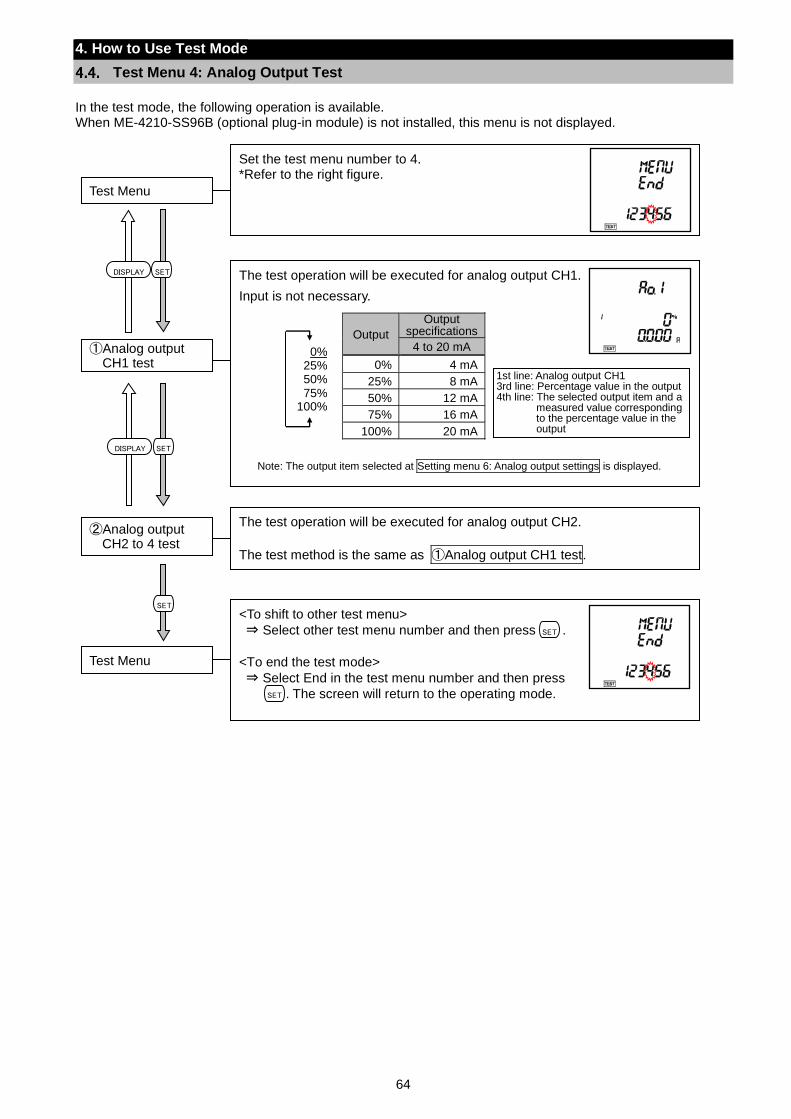
64
4. How to Use Test Mode
Test Menu 4: Analog Output Test
In the test mode, the following operation is available. When ME-4210-SS96B (optional plug-in module) is not installed, this menu is not displayed.
Set the test menu number to 4. *Refer to the right figure.
Test Menu
The test operation will be executed for analog output CH1.
Input is not necessary.
Output
Output specifications
4 to 20 mA
0% 4 mA
25% 8 mA
50% 12 mA
75% 16 mA
100% 20 mA
①Analog output CH1 test
Note: The output item selected at Setting menu 6: Analog output settings is displayed.
1st line: Analog output CH1 3rd line: Percentage value in the output 4th line: The selected output item and a
measured value corresponding to the percentage value in the output
0% 25% 50% 75%
100%
The test operation will be executed for analog output CH2.
The test method is the same as ①Analog output CH1 test.
②Analog output CH2 to 4 test
<To shift to other test menu>
⇒ Select other test menu number and then press .
<To end the test mode>
⇒ Select End in the test menu number and then press .
. The screen will return to the operating mode.
Test Menu
SET
SET
SET
SETDISPLAY
SETDISPLAY
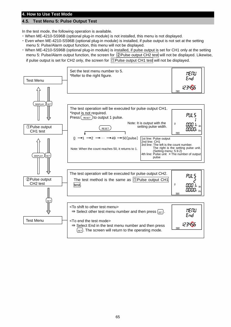
65
4. How to Use Test Mode
Test Menu 5: Pulse Output Test
In the test mode, the following operation is available.
・ When ME-4210-SS96B (optional plug-in module) is not installed, this menu is not displayed.
・ Even when ME-4210-SS96B (optional plug-in module) is installed, if pulse output is not set at the setting menu 5: Pulse/Alarm output function, this menu will not be displayed.
・ When ME-4210-SS96B (optional plug-in module) is installed, if pulse output is set for CH1 only at the setting
menu 5: Pulse/Alarm output function, the screen for ②Pulse output CH2 test will not be displayed. Likewise,
if pulse output is set for CH2 only, the screen for ①Pulse output CH1 test will not be displayed.
Set the test menu number to 5. *Refer to the right figure. Test Menu
The test operation will be executed for pulse output CH1. *Input is not required. Press to output 1 pulse. ①Pulse output
CH1 test
0 1 2 ・・・ 49 50[pulse]
Note: It is output with the setting pulse width.
RESET
RESET
Note: When the count reaches 50, it returns to 1.
1st line: Pulse output 2nd line: CH1 3rd line: The left is the count number.
The right is the setting pulse unit. (Setting menu: 5.9.2)
4th line: Pulse unit ×The number of output pulse
The test operation will be executed for pulse output CH2.
The test method is the same as ①Pulse output CH1
test.
②Pulse output CH2 test
<To shift to other test menu>
⇒ Select other test menu number and then press .
<To end the test mode>
⇒ Select End in the test menu number and then press .
. The screen will return to the operating mode.
Test Menu
SET
SET
SET
SETDISPLAY
SETDISPLAY
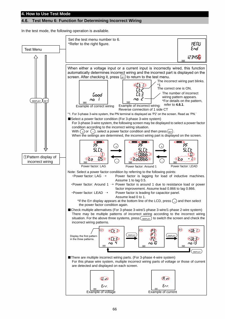
66
4. How to Use Test Mode
Test Menu 6: Function for Determining Incorrect Wiring
In the test mode, the following operation is available.
Set the test menu number to 6. *Refer to the right figure.
Test Menu
When either a voltage input or a current input is incorrectly wired, this function automatically determines incorrect wiring and the incorrect part is displayed on the screen. After checking it, press to return to the test menu.
*1. For 3-phase 3-wire system, the PN terminal is displayed as ‘P2’ on the screen. Read as ‘PN.’
Select a power factor condition (For 3-phase 3-wire system)
For 3-phase 3-wire system, the following screen may be displayed to select a power factor
condition according to the incorrect wiring situation.
With or , select a power factor condition and then press .
When the settings are determined, the incorrect wiring part is displayed on the screen.
Note: Select a power factor condition by referring to the following points:
・Power factor: LAG Power factor is lagging for load of inductive machines.
Assume 1 to lag 0.5.
・Power factor: Around 1 Power factor is around 1 due to resistance load or power
factor improvement. Assume lead 0.866 to lag 0.866.
・Power factor: LEAD Power factor is leading for capacitor panel.
Assume lead 0 to 1. *If the Err display appears at the bottom line of the LCD, press and then select the power factor condition again.
Check multiple alternatives (For 3-phase 3-wire/1-phase 3-wire/1-phase 2-wire system)
There may be multiple patterns of incorrect wiring according to the incorrect wiring
situation. For the above three systems, press to switch the screen and check the
incorrect wiring patterns.
There are multiple incorrect wiring parts. (For 3-phase 4-wire system)
For this phase wire system, multiple incorrect wiring parts of voltage or those of current
are detected and displayed on each screen.
①Pattern display of
incorrect wiring
Example of correct wiring
SETDISPLAY
DISPLAY DISPLAY
DISPLAY
Display the first pattern in the three patterns.
Example of voltage Example of current
+
DISPLAY
- SET
-
Example of incorrect wiring: Reverse connection of 1 side CT
The incorrect wiring part blinks. *1 The correct one is ON.
The number of incorrect wiring pattern appears. *For details on the pattern, refer to 4.6.1.
Power factor: LAG Power factor: Around 1 Power factor: LEAD
+ +
- -
SET
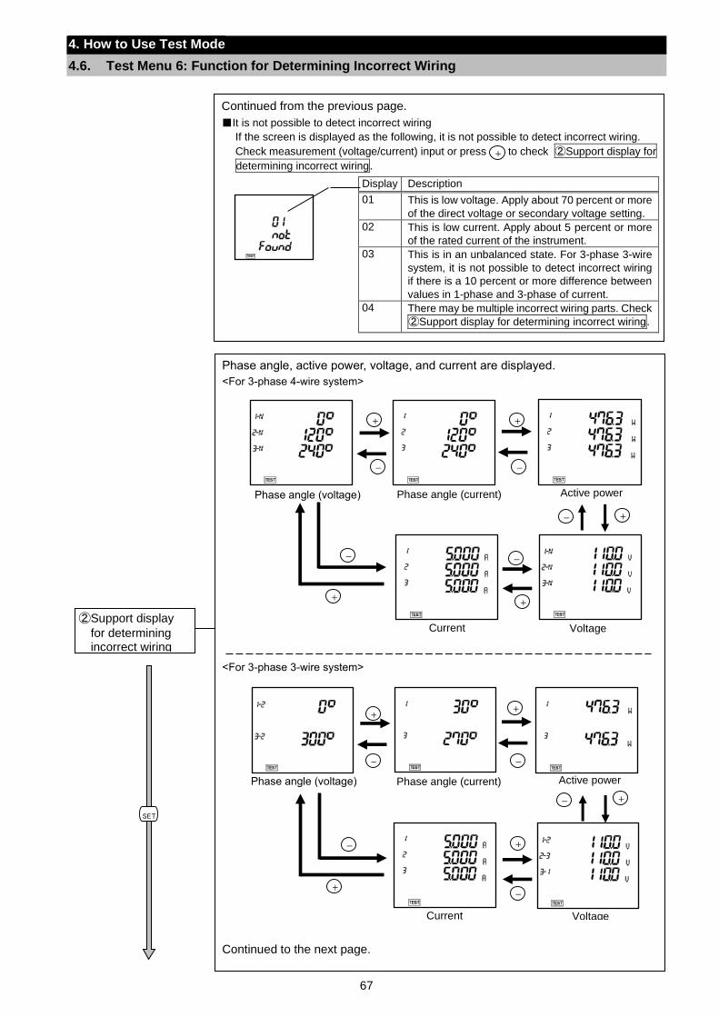
67
4. How to Use Test Mode
4.6. Test Menu 6: Function for Determining Incorrect Wiring
Continued from the previous page.
It is not possible to detect incorrect wiring
If the screen is displayed as the following, it is not possible to detect incorrect wiring.
Check measurement (voltage/current) input or press to check ②Support display for
determining incorrect wiring.
Display Description
01 This is low voltage. Apply about 70 percent or more
of the direct voltage or secondary voltage setting.
02 This is low current. Apply about 5 percent or more
of the rated current of the instrument.
03 This is in an unbalanced state. For 3-phase 3-wire
system, it is not possible to detect incorrect wiring
if there is a 10 percent or more difference between
values in 1-phase and 3-phase of current.
04 There may be multiple incorrect wiring parts. Check
②Support display for determining incorrect wiring.
.
+
Phase angle, active power, voltage, and current are displayed.
<For 3-phase 4-wire system>
<For 3-phase 3-wire system>
Continued to the next page.
②Support display
for determining incorrect wiring
SET
Active power
Voltage
Current
+
-
+
-
+
-
+-
+
-
Phase angle (current) Phase angle (voltage)
Active power Phase angle (current)
Voltage
++
- -
+-
+
-
Current
Phase angle (voltage)
+
-
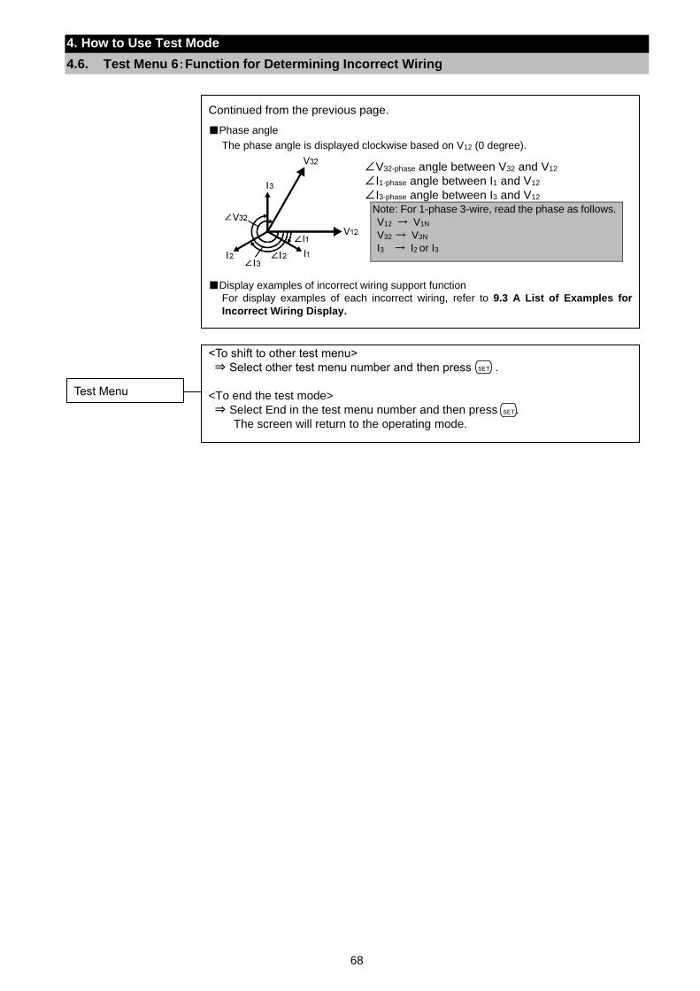
68
4. How to Use Test Mode
4.6. Test Menu 6:Function for Determining Incorrect Wiring
Continued from the previous page.
Phase angle
The phase angle is displayed clockwise based on V12 (0 degree).
Display examples of incorrect wiring support function
For display examples of each incorrect wiring, refer to 9.3 A List of Examples for
Incorrect Wiring Display.
∠V32-phase angle between V32 and V12
∠I1-phase angle between I1 and V12
∠I3-phase angle between I3 and V12 Note: For 1-phase 3-wire, read the phase as follows.
V12 → V1N
V32 → V3N
I3 → I2 or I3
<To shift to other test menu>
⇒ Select other test menu number and then press .
<To end the test mode>
⇒ Select End in the test menu number and then press .
The screen will return to the operating mode.
Test Menu
SET
SET
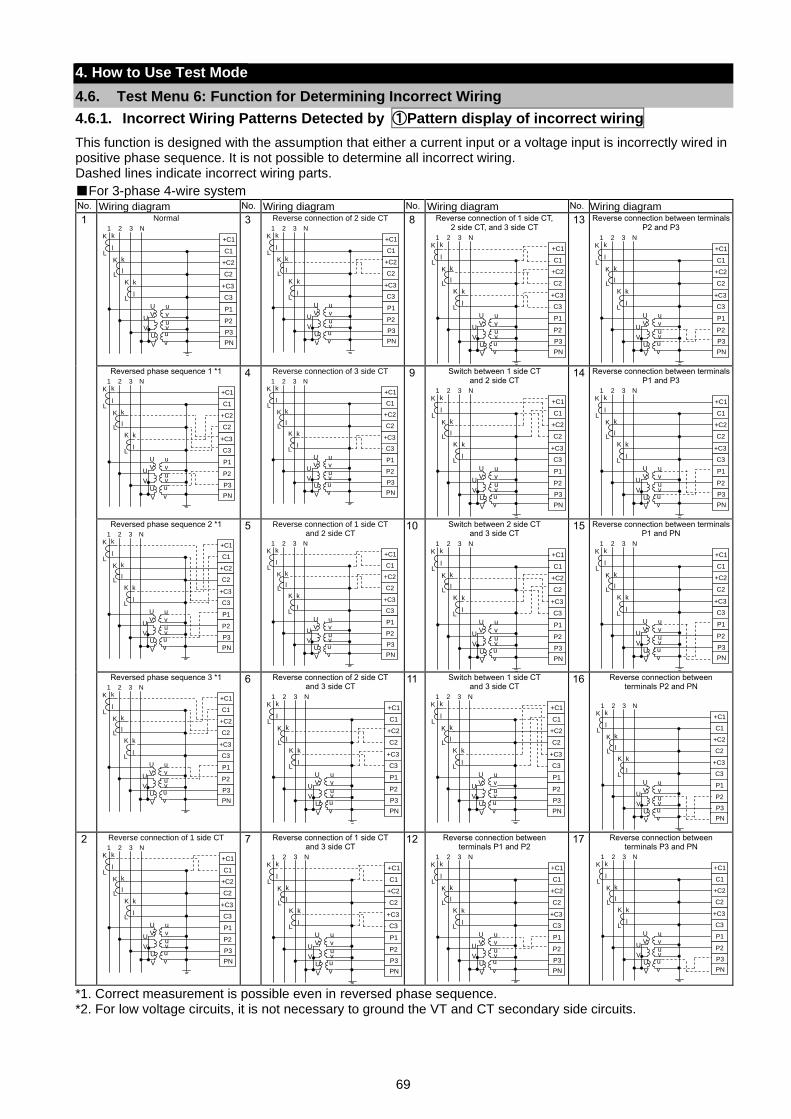
69
4. How to Use Test Mode
4.6. Test Menu 6: Function for Determining Incorrect Wiring
4.6.1. Incorrect Wiring Patterns Detected by ①Pattern display of incorrect wiring
This function is designed with the assumption that either a current input or a voltage input is incorrectly wired in positive phase sequence. It is not possible to determine all incorrect wiring. Dashed lines indicate incorrect wiring parts.
For 3-phase 4-wire system No. Wiring diagram No. Wiring diagram No. Wiring diagram No. Wiring diagram
1 Normal
3 Reverse connection of 2 side CT
8 Reverse connection of 1 side CT, 2 side CT, and 3 side CT
13 Reverse connection between terminals P2 and P3
Reversed phase sequence 1 *1
4 Reverse connection of 3 side CT
9 Switch between 1 side CT and 2 side CT
14 Reverse connection between terminals P1 and P3
Reversed phase sequence 2 *1
5 Reverse connection of 1 side CT and 2 side CT
10 Switch between 2 side CT and 3 side CT
15 Reverse connection between terminals P1 and PN
Reversed phase sequence 3 *1
6 Reverse connection of 2 side CT and 3 side CT
11 Switch between 1 side CT and 3 side CT
16 Reverse connection between terminals P2 and PN
2 Reverse connection of 1 side CT
7 Reverse connection of 1 side CT and 3 side CT
12 Reverse connection between terminals P1 and P2
17 Reverse connection between terminals P3 and PN
*1. Correct measurement is possible even in reversed phase sequence. *2. For low voltage circuits, it is not necessary to ground the VT and CT secondary side circuits.
+C2
C2
+C3
C3
P1
P3
P2
+C1
C1
PN
1 2 3 NK
L
k
l
K
L
k
l
K
L
k
l
U u
V vU
V vu
v
uU
V
+C2
C2
+C3
C3
P1
P3
P2
+C1
C1
PN
1 2 3 NK
L
k
l
K
L
k
l
K
L
k
l
U u
V vU
V vu
v
uU
V
+C2
C2
+C3
C3
P1
P3
P2
+C1
C1
PN
1 2 3 NK
L
k
l
K
L
k
l
K
L
k
l
U u
V vU
V vu
v
uU
V
+C2
C2
+C3
C3
P1
P3
P2
+C1
C1
PN
1 2 3 NK
L
k
l
K
L
k
l
K
L
k
l
U u
V vU
V vu
v
uU
V
+C2
C2
+C3
C3
P1
P3
P2
+C1
C1
PN
1 2 3 N
K
L
k
l
K
L
k
l
K
L
k
l
U u
V vU
V vu
v
uU
V
+C2
C2
+C3
C3
P1
P3
P2
+C1
C1
PN
1 2 3 NK
L
k
l
K
L
k
l
K
L
k
l
U u
V vU
V vu
v
uU
V
+C2
C2
+C3
C3
P1
P3
P2
+C1
C1
PN
1 2 3 NK
L
k
l
K
L
k
l
K
L
k
l
U u
V vU
V vu
v
uU
V
+C2
C2
+C3
C3
P1
P3
P2
+C1
C1
PN
1 2 3 N
K
L
k
l
K
L
k
l
K
L
k
l
U u
V vU
V vu
v
uU
V
+C2
C2
+C3
C3
P1
P3
P2
+C1
C1
PN
1 2 3 N
K
L
k
l
K
L
k
l
K
L
k
l
U u
V vU
V vu
v
uU
V
+C2
C2
+C3
C3
P1
P3
P2
+C1
C1
PN
1 2 3 NK
L
k
l
K
L
k
l
K
L
k
l
U u
V vU
V vu
v
uU
V
+C2
C2
+C3
C3
P1
P3
P2
+C1
C1
PN
1 2 3 NK
L
k
l
K
L
k
l
K
L
k
l
U u
V vU
V vu
v
uU
V
+C2
C2
+C3
C3
P1
P3
P2
+C1
C1
PN
1 2 3 NK
L
k
l
K
L
k
l
K
L
k
l
U u
V vU
V vu
v
uU
V
+C2
C2
+C3
C3
P1
P3
P2
+C1
C1
PN
1 2 3 N
K
L
k
l
K
L
k
l
K
L
k
l
U u
V vU
V vu
v
uU
V
+C2
C2
+C3
C3
P1
P3
P2
+C1
C1
PN
1 2 3 NK
L
k
l
K
L
k
l
K
L
k
l
U u
V vU
V vu
v
uU
V
+C2
C2
+C3
C3
P1
P3
P2
+C1
C1
PN
1 2 3 NK
L
k
l
K
L
k
l
K
L
k
l
U u
V vU
V vu
v
uU
V
+C2
C2
+C3
C3
P1
P3
P2
+C1
C1
PN
1 2 3 N
K
L
k
l
K
L
k
l
K
L
k
l
U u
V vU
V vu
v
uU
V
+C2
C2
+C3
C3
P1
P3
P2
+C1
C1
PN
1 2 3 NK
L
k
l
K
L
k
l
K
L
k
l
U u
V vU
V vu
v
uU
V
+C2
C2
+C3
C3
P1
P3
P2
+C1
C1
PN
1 2 3 NK
L
k
l
K
L
k
l
K
L
k
l
U u
V vU
V vu
v
uU
V
+C2
C2
+C3
C3
P1
P3
P2
+C1
C1
PN
1 2 3 NK
L
k
l
K
L
k
l
K
L
k
l
U u
V vU
V vu
v
uU
V
+C2
C2
+C3
C3
P1
P3
P2
+C1
C1
PN
1 2 3 NK
L
k
l
K
L
k
l
K
L
k
l
U u
V vU
V vu
v
uU
V
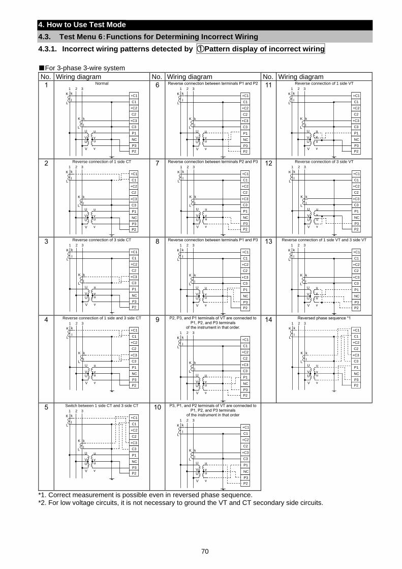
70
4. How to Use Test Mode
4.3. Test Menu 6:Functions for Determining Incorrect Wiring
4.3.1. Incorrect wiring patterns detected by ①Pattern display of incorrect wiring
For 3-phase 3-wire system
No. Wiring diagram No. Wiring diagram No. Wiring diagram
1 Normal
6 Reverse connection between terminals P1 and P2
11 Reverse connection of 1 side VT
2 Reverse connection of 1 side CT
7 Reverse connection between terminals P2 and P3
12 Reverse connection of 3 side VT
3 Reverse connection of 3 side CT
8 Reverse connection between terminals P1 and P3
13 Reverse connection of 1 side VT and 3 side VT
4 Reverse connection of 1 side and 3 side CT
9 P2, P3, and P1 terminals of VT are connected to P1, P2, and P3 terminals
of the instrument in that order.
14 Reversed phase sequence *1
5 Switch between 1 side CT and 3 side CT
10 P3, P1, and P2 terminals of VT are connected to P1, P2, and P3 terminals
of the instrument in that order
*1. Correct measurement is possible even in reversed phase sequence. *2. For low voltage circuits, it is not necessary to ground the VT and CT secondary side circuits.
+C2
C2
+C3
C3
P1
P3
NC
+C1
C1
P2
K
L
k
l
K
L
k
l
U u
V vU u
V v
1 2 3
+C2
C2
+C3
C3
P1
P3
NC
+C1
C1
P2
K
L
k
l
K
L
k
l
U u
V vU u
V v
1 2 3
+C2
C2
+C3
C3
P1
P3
NC
+C1
C1
P2
K
L
k
l
K
L
k
l
U u
V v
U u
V v
1 2 3
+C2
C2
+C3
C3
P1
P3
NC
+C1
C1
P2
K
L
k
l
K
L
k
l
U u
V vU u
V v
1 2 3
+C2
C2
+C3
C3
P1
P3
NC
+C1
C1
P2
K
L
k
l
K
L
k
l
U u
V vU u
V v
1 2 3
+C2
C2
+C3
C3
P1
P3
NC
+C1
C1
P2
K
L
k
l
K
L
k
l
U u
V v
U u
V v
1 2 3
+C2
C2
+C3
C3
P1
P3
NC
+C1
C1
P2
K
L
k
l
K
L
k
l
U u
V vU u
V v
1 2 3
+C2
C2
+C3
C3
P1
P3
NC
+C1
C1
P2
K
L
k
l
K
L
k
l
U u
V vU u
V v
1 2 3
+C2
C2
+C3
C3
P1
P3
NC
+C1
C1
P2
K
L
k
l
K
L
k
l
U u
V v
U u
V v
1 2 3
+C2
C2
+C3
C3
P1
P3
NC
+C1
C1
P2
K
L
k
l
K
L
k
l
U u
V vU u
V v
1 2 3
+C2
C2
+C3
C3
P1
P3
NC
+C1
C1
P2
K
L
k
l
K
L
k
l
U u
V vU u
V v
1 2 3
+C2
C2
+C3
C3
P1
P3
NC
+C1
C1
P2
K
L
k
l
K
L
k
l
U u
V vU u
V v
1 2 3
+C2
C2
+C3
C3
P1
P3
NC
+C1
C1
P2
K
L
k
l
K
L
k
l
U u
V vU u
V v
1 2 3
+C2
C2
+C3
C3
P1
P3
NC
+C1
C1
P2
K
L
k
l
K
L
k
l
U u
V vU u
V v
1 2 3
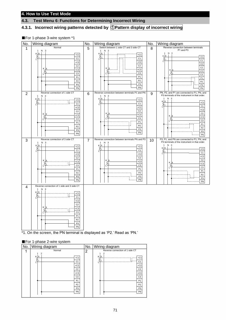
71
4. How to Use Test Mode
4.3. Test Menu 6:Functions for Determining Incorrect Wiring
4.3.1. Incorrect wiring patterns detected by ①Pattern display of incorrect wiring
For 1-phase 3-wire system *1
No. Wiring diagram No. Wiring diagram No. Wiring diagram
1 Normal
5 Switch between 1 side CT and 3 side CT
8 Reverse connection between terminals P1 and P3
2 Reverse connection of 1 side CT
6 Reverse connection between terminals P1 and PN
9 PN, P2, and P1 are connected to P1, PN, and P3 terminals of the instrument in that order.
3 Reverse connection of 3 side CT
7 Reverse connection between terminals PN and P3
10 P3, P1, and PN are connected to P1, PN, and P3 terminals of the instrument in that order.
4 Reverse connection of 1 side and 3 side CT
*1. On the screen, the PN terminal is displayed as ‘P2.’ Read as ‘PN.’
For 1-phase 2-wire system
No. Wiring diagram No. Wiring diagram
1 Normal
2 Reverse connection of 1 side CT
+C2
C2
+C3
C3
P1
P3
P2
+C1
C1
PN
K
L
k
l
K
L
k
l
1 N 3
+C2
C2
+C3
C3
P1
P3
P2
+C1
C1
PN
K
L
k
l
K
L
k
l
1 N 3
+C2
C2
+C3
C3
P1
P3
P2
+C1
C1
PN
K
L
k
l
K
L
k
l
1 N 3
+C2
C2
+C3
C3
P1
P3
P2
+C1
C1
PN
K
L
k
l
K
L
k
l
1 N 3
+C2
C2
+C3
C3
P1
P3
P2
+C1
C1
PN
K
L
k
l
K
L
k
l
1 N 3
+C2
C2
+C3
C3
P1
P3
P2
+C1
C1
PN
K
L
k
l
K
L
k
l
1 N 3
+C2
C2
+C3
C3
P1
P3
P2
+C1
C1
PN
K
L
k
l
K
L
k
l
1 N 3
+C2
C2
+C3
C3
P1
P3
P2
+C1
C1
PN
K
L
k
l
K
L
k
l
1 N 3
+C2
C2
+C3
C3
P1
P3
P2
+C1
C1
PN
K
L
k
l
K
L
k
l
1 N 3
+C2
C2
+C3
C3
P1
P3
P2
+C1
C1
PN
K
L
k
l
K
L
k
l
1 N 3
+C2
C2
+C3
C3
P1
P3
P2
+C1
C1
PN
K
L
k
l
1 2
+C2
C2
+C3
C3
P1
P3
P2
+C1
C1
PN
K
L
k
l
1 2
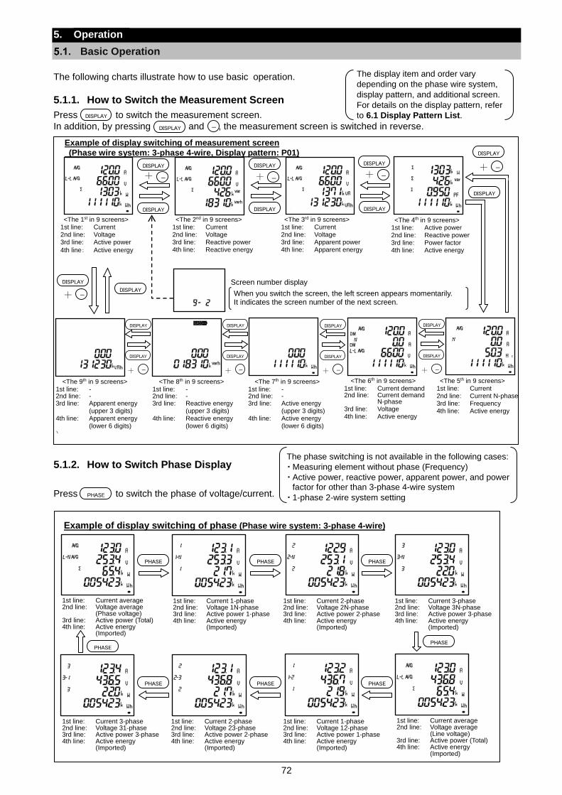
72
5. Operation
Basic Operation
The following charts illustrate how to use basic operation.
5.1.1. How to Switch the Measurement Screen
Press to switch the measurement screen.
In addition, by pressing and , the measurement screen is switched in reverse.
5.1.2. How to Switch Phase Display
Press to switch the phase of voltage/current.
The display item and order vary
depending on the phase wire system,
display pattern, and additional screen.
For details on the display pattern, refer
to 6.1 Display Pattern List.
The phase switching is not available in the following cases:
・ Measuring element without phase (Frequency)
・ Active power, reactive power, apparent power, and power factor for other than 3-phase 4-wire system
・ 1-phase 2-wire system setting PHASE
DISPLAY
Example of display switching of phase (Phase wire system: 3-phase 4-wire)
1st line: Current average 2nd line: Voltage average
(Phase voltage) 3rd line: Active power (Total) 4th line: Active energy
(Imported)
PHASE PHASEPHASE
PHASE PHASEPHASE
1st line: Current 1-phase 2nd line: Voltage 1N-phase 3rd line: Active power 1-phase 4th line: Active energy
(Imported)
PHASE
1st line: Current 2-phase 2nd line: Voltage 2N-phase 3rd line: Active power 2-phase 4th line: Active energy
(Imported)
1st line: Current 3-phase 2nd line: Voltage 3N-phase 3rd line: Active power 3-phase 4th line: Active energy
(Imported)
PHASE
1st line: Current average 2nd line: Voltage average
(Line voltage) 3rd line: Active power (Total) 4th line: Active energy
(Imported)
1st line: Current 1-phase 2nd line: Voltage 12-phase 3rd line: Active power 1-phase 4th line: Active energy
(Imported)
1st line: Current 2-phase 2nd line: Voltage 23-phase 3rd line: Active power 2-phase 4th line: Active energy
(Imported)
1st line: Current 3-phase 2nd line: Voltage 31-phase 3rd line: Active power 3-phase 4th line: Active energy
(Imported)
-
Example of display switching of measurement screen
(Phase wire system: 3-phase 4-wire, Display pattern: P01)
<The 1st in 9 screens> 1st line: Current 2nd line: Voltage 3rd line: Active power
4th line: Active energy
<The 2nd in 9 screens> 1st line: Current 2nd line: Voltage 3rd line: Reactive power 4th line: Reactive energy
<The 3rd in 9 screens> 1st line: Current 2nd line: Voltage 3rd line: Apparent power 4th line: Apparent energy
When you switch the screen, the left screen appears momentarily. It indicates the screen number of the next screen.
Screen number display
DISPLAYDISPLAYDISPLAY
<The 4th in 9 screens> 1st line: Active power 2nd line: Reactive power 3rd line: Power factor 4th line: Active energy
DISPLAYDISPLAYDISPLAY
-+ -+ -+
DISPLAY
-+
DISPLAY
<The 5th in 9 screens> 1st line: Current 2nd line: Current N-phase 3rd line: Frequency 4th line: Active energy
<The 6th in 9 screens> 1st line: Current demand 2nd line: Current demand
N-phase 3rd line: Voltage 4th line: Active energy
DISPLAY
DISPLAY
-+
<The 7th in 9 screens> 1st line: - 2nd line: - 3rd line: Active energy
(upper 3 digits) 4th line: Active energy
(lower 6 digits)
<The 8th in 9 screens> 1st line: - 2nd line: - 3rd line: Reactive energy
(upper 3 digits) 4th line: Reactive energy
(lower 6 digits)
<The 9th in 9 screens> 1st line: - 2nd line: - 3rd line: Apparent energy
(upper 3 digits) 4th line: Apparent energy
(lower 6 digits)
)
DISPLAY
DISPLAY
-+
DISPLAY
DISPLAY
-+
DISPLAY
DISPLAY
-+
DISPLAY
DISPLAY
-+
DISPLAY
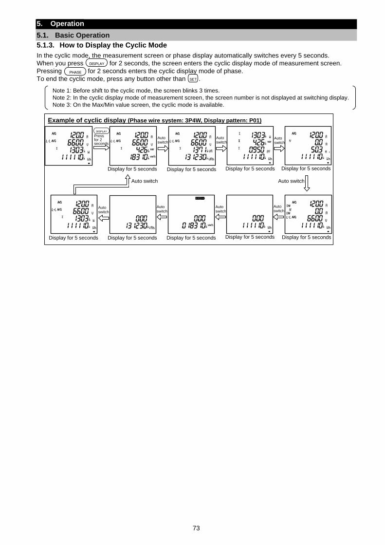
73
5. Operation
5.1. Basic Operation
5.1.3. How to Display the Cyclic Mode
In the cyclic mode, the measurement screen or phase display automatically switches every 5 seconds.
When you press for 2 seconds, the screen enters the cyclic display mode of measurement screen.
Pressing for 2 seconds enters the cyclic display mode of phase.
To end the cyclic mode, press any button other than .
Note 1: Before shift to the cyclic mode, the screen blinks 3 times.
Note 2: In the cyclic display mode of measurement screen, the screen number is not displayed at switching display.
Note 3: On the Max/Min value screen, the cyclic mode is available.
DISPLAY
PHASE
SET
u Example of cyclic display (Phase wire system: 3P4W, Display pattern: P01)
DISPLAY
Press for 2 seconds
Display for 5 seconds Display for 5 seconds Display for 5 seconds Display for 5 seconds
Display for 5 seconds Display for 5 seconds Display for 5 seconds Display for 5 seconds Display for 5 seconds
Auto switch Auto switch
Auto switch
Auto switch
Auto switch
Auto switch
Auto switch
Auto switch
Auto switch
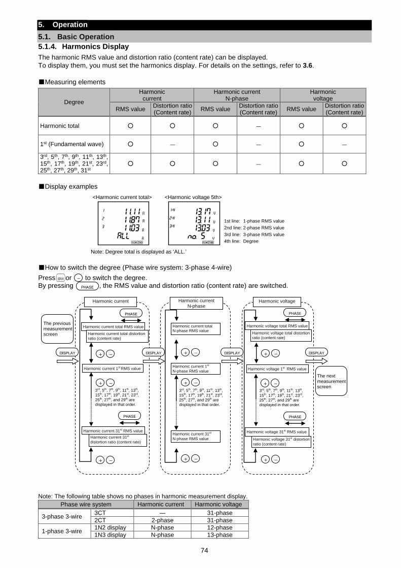
74
5. Operation
5.1. Basic Operation
5.1.4. Harmonics Display
The harmonic RMS value and distortion ratio (content rate) can be displayed.
To display them, you must set the harmonics display. For details on the settings, refer to 3.6.
Measuring elements
Degree
Harmonic current
Harmonic current N-phase
Harmonic voltage
RMS value Distortion ratio (Content rate)
RMS value Distortion ratio (Content rate)
RMS value Distortion ratio (Content rate)
Harmonic total ―
1st (Fundamental wave) ― ― ―
3rd, 5th, 7th, 9th, 11th, 13th, 15th, 17th, 19th, 21st, 23rd, 25th, 27th, 29th, 31st
―
Display examples
Note: Degree total is displayed as ‘ALL.’
How to switch the degree (Phase wire system: 3-phase 4-wire)
Press or to switch the degree. By pressing , the RMS value and distortion ratio (content rate) are switched.
Note: The following table shows no phases in harmonic measurement display.
Phase wire system Harmonic current Harmonic voltage
3-phase 3-wire 3CT ― 31-phase
2CT 2-phase 31-phase
1-phase 3-wire 1N2 display N-phase 12-phase
1N3 display N-phase 13-phase
PHASE
<Harmonic current total> <Harmonic voltage 5th>
1st line: 1-phase RMS value
2nd line: 2-phase RMS value
3rd line: 3-phase RMS value
4th line: Degree
DISPLAY -
+ -
Harmonic current N-phase
Harmonic current total N-phase RMS value
+ -
+ -
3rd, 5th, 7th, 9th, 11th, 13th,
15th, 17th, 19th, 21st, 23rd, 25th, 27th, and 29th are displayed in that order.
+ -
Harmonic current
Harmonic current total RMS value
+ -
+ -
3rd, 5th, 7th, 9th, 11th, 13th, 15th, 17th, 19th, 21st, 23rd,
25th, 27th, and 29th are displayed in that order.
PHASE
DISPLAY DISPLAY + -
Harmonic voltage
Harmonic voltage total RMS value
+ -
+ -
PHASE
DISPLAY
The previous measurement screen
The next measurement screen
Harmonic current total distortion ratio (content rate)
Harmonic current 1st RMS value
Harmonic current 31st RMS value
Harmonic current 31st
distortion ratio (content rate)
3rd, 5th, 7th, 9th, 11th, 13th,
15th, 17th, 19th, 21st, 23rd, 25th, 27th, and 29th are displayed in that order.
Harmonic current 1st
N-phase RMS value
Harmonic current 31st
N-phase RMS value
Harmonic voltage 1st RMS value
Harmonic voltage 31st RMS value
Harmonic voltage 31st distortion
ratio (content rate)
PHASE
Harmonic voltage total distortion ratio (content rate)
PHASE
DISPLAY
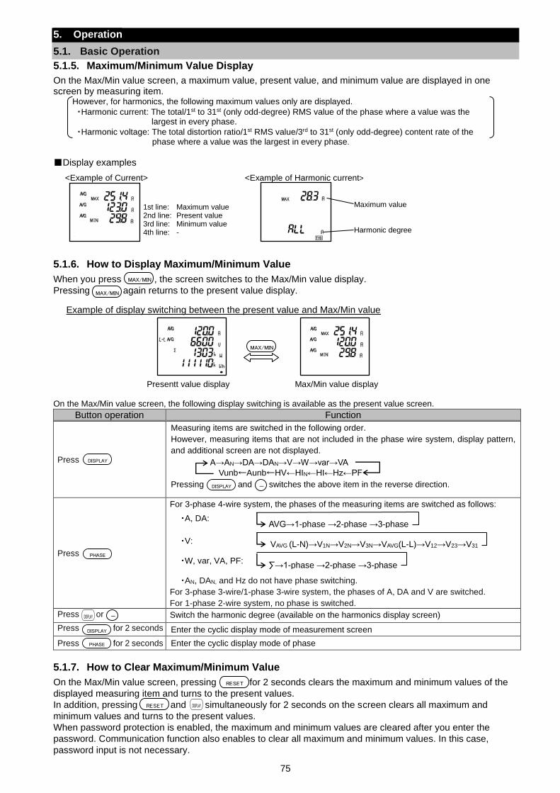
75
5. Operation
5.1. Basic Operation
5.1.5. Maximum/Minimum Value Display
On the Max/Min value screen, a maximum value, present value, and minimum value are displayed in one screen by measuring item.
However, for harmonics, the following maximum values only are displayed.
・Harmonic current: The total/1st to 31st (only odd-degree) RMS value of the phase where a value was the largest in every phase.
・Harmonic voltage: The total distortion ratio/1st RMS value/3rd to 31st (only odd-degree) content rate of the phase where a value was the largest in every phase.
Display examples
5.1.6. How to Display Maximum/Minimum Value
When you press , the screen switches to the Max/Min value display.
Pressing again returns to the present value display.
On the Max/Min value screen, the following display switching is available as the present value screen.
Button operation Function
Press
Measuring items are switched in the following order.
However, measuring items that are not included in the phase wire system, display pattern,
and additional screen are not displayed.
Pressing and switches the above item in the reverse direction.
Press
For 3-phase 4-wire system, the phases of the measuring items are switched as follows:
・A, DA:
・V:
・W, var, VA, PF:
・AN, DAN, and Hz do not have phase switching.
For 3-phase 3-wire/1-phase 3-wire system, the phases of A, DA and V are switched.
For 1-phase 2-wire system, no phase is switched.
Press or Switch the harmonic degree (available on the harmonics display screen)
Press for 2 seconds Enter the cyclic display mode of measurement screen
Press for 2 seconds Enter the cyclic display mode of phase
5.1.7. How to Clear Maximum/Minimum Value
On the Max/Min value screen, pressing for 2 seconds clears the maximum and minimum values of the
displayed measuring item and turns to the present values.
In addition, pressing and simultaneously for 2 seconds on the screen clears all maximum and
minimum values and turns to the present values.
When password protection is enabled, the maximum and minimum values are cleared after you enter the
password. Communication function also enables to clear all maximum and minimum values. In this case,
password input is not necessary.
MAX/MIN
MAX/MIN
RESET
DISPLAY
PHASE
DISPLAY
PHASE
1st line: Maximum value 2nd line: Present value 3rd line: Minimum value 4th line: -
<Example of Current> <Example of Harmonic current>
Maximum value
Harmonic degree
Example of display switching between the present value and Max/Min value
Presentt value display Max/Min value display
MAX/MIN
DISPLAY -
DISPLAYRESET
AVG→1-phase →2-phase →3-phase
∑→1-phase →2-phase →3-phase
VAVG (L-N)→V1N→V2N→V3N→VAVG(L-L)→V12→V23→V31
A→AN→DA→DAN→V→W→var→VA
Vunb←Aunb←HV←HIN←HI←Hz←PF
DISPLAY -
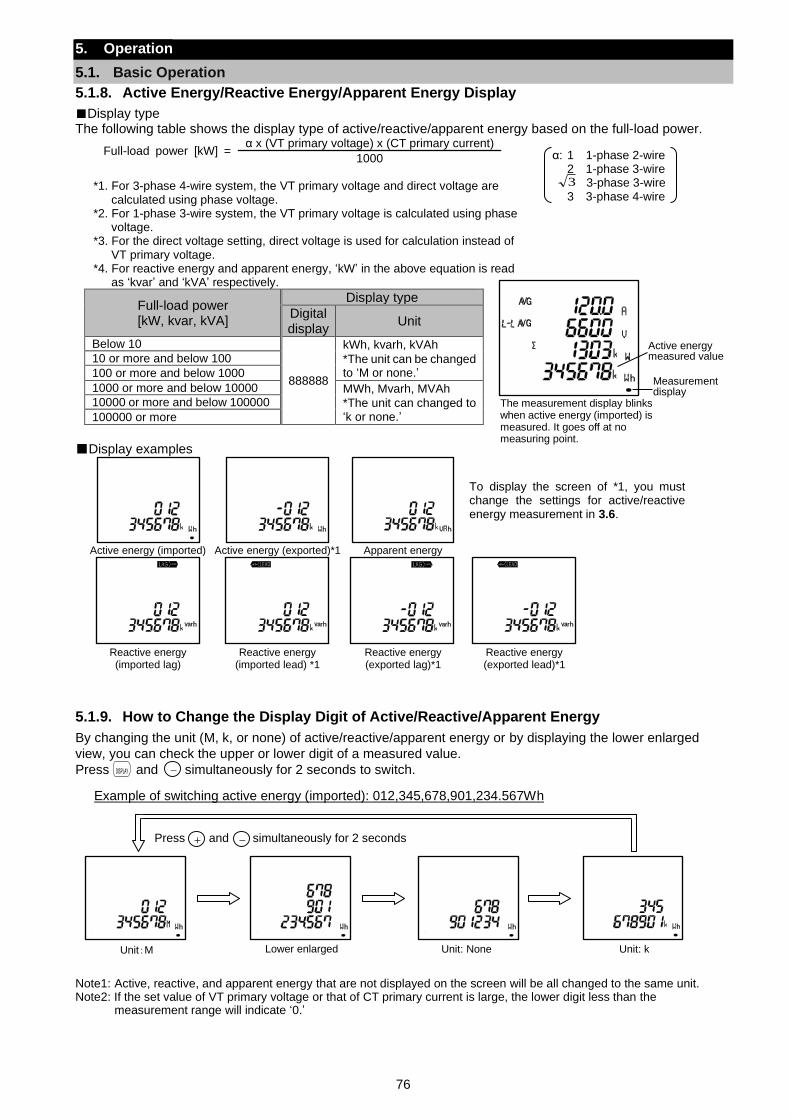
76
5. Operation
5.1. Basic Operation
5.1.8. Active Energy/Reactive Energy/Apparent Energy Display
Display type
The following table shows the display type of active/reactive/apparent energy based on the full-load power.
Full-load power [kW] = α x (VT primary voltage) x (CT primary current)
1000 *1. For 3-phase 4-wire system, the VT primary voltage and direct voltage are
calculated using phase voltage. *2. For 1-phase 3-wire system, the VT primary voltage is calculated using phase
voltage. *3. For the direct voltage setting, direct voltage is used for calculation instead of
VT primary voltage. *4. For reactive energy and apparent energy, ‘kW’ in the above equation is read
as ‘kvar’ and ‘kVA’ respectively.
Full-load power [kW, kvar, kVA]
Display type
Digital display
Unit
Below 10
888888
kWh, kvarh, kVAh
*The unit can be changed to ‘M or none.’
10 or more and below 100
100 or more and below 1000
1000 or more and below 10000 MWh, Mvarh, MVAh
*The unit can changed to ‘k or none.’
10000 or more and below 100000
100000 or more
Display examples
To display the screen of *1, you must change the settings for active/reactive energy measurement in 3.6.
Active energy (imported) Active energy (exported)*1 Apparent energy
Reactive energy (imported lag)
Reactive energy (imported lead) *1
Reactive energy (exported lag)*1
Reactive energy (exported lead)*1
5.1.9. How to Change the Display Digit of Active/Reactive/Apparent Energy
By changing the unit (M, k, or none) of active/reactive/apparent energy or by displaying the lower enlarged
view, you can check the upper or lower digit of a measured value.
Press and simultaneously for 2 seconds to switch.
Note1: Active, reactive, and apparent energy that are not displayed on the screen will be all changed to the same unit. Note2: If the set value of VT primary voltage or that of CT primary current is large, the lower digit less than the
measurement range will indicate ‘0.’
α: 1 1-phase 2-wire 2 1-phase 3-wire 3-phase 3-wire 3 3-phase 4-wire
DISPLAY -
The measurement display blinks when active energy (imported) is measured. It goes off at no measuring point.
Active energy measured value
Measurement display
Example of switching active energy (imported): 012,345,678,901,234.567Wh
Unit:M Lower enlarged Unit: None Unit: k
Press and simultaneously for 2 seconds + -
3
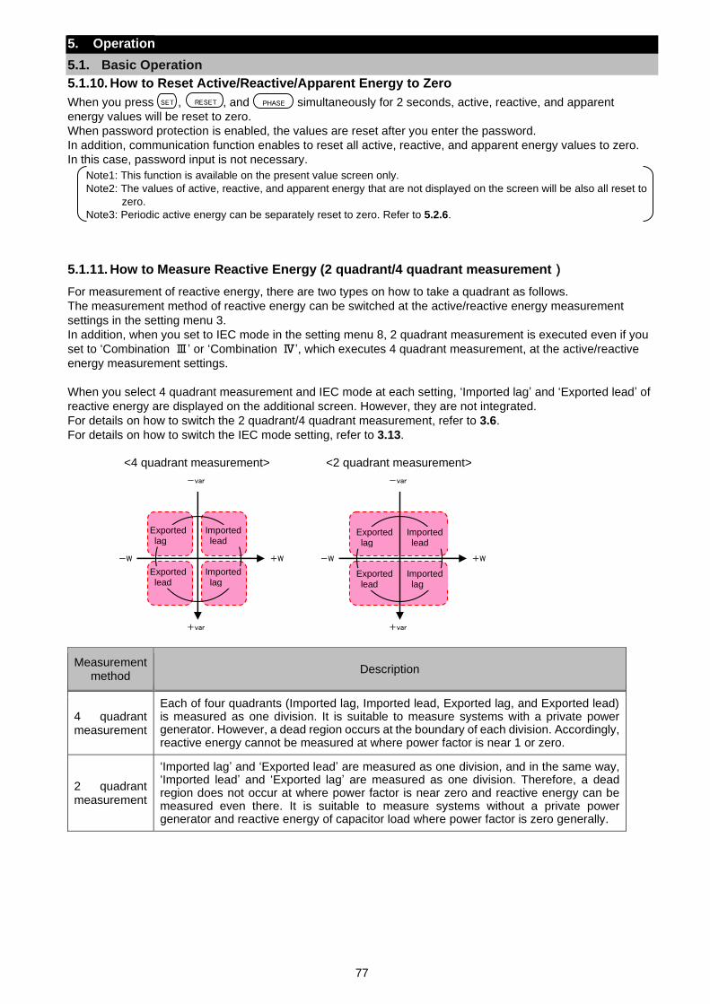
77
5. Operation
5.1. Basic Operation
5.1.10. How to Reset Active/Reactive/Apparent Energy to Zero
When you press , , and simultaneously for 2 seconds, active, reactive, and apparent
energy values will be reset to zero.
When password protection is enabled, the values are reset after you enter the password.
In addition, communication function enables to reset all active, reactive, and apparent energy values to zero.
In this case, password input is not necessary.
Note1: This function is available on the present value screen only.
Note2: The values of active, reactive, and apparent energy that are not displayed on the screen will be also all reset to
zero.
Note3: Periodic active energy can be separately reset to zero. Refer to 5.2.6.
5.1.11. How to Measure Reactive Energy (2 quadrant/4 quadrant measurement)
For measurement of reactive energy, there are two types on how to take a quadrant as follows.
The measurement method of reactive energy can be switched at the active/reactive energy measurement
settings in the setting menu 3.
In addition, when you set to IEC mode in the setting menu 8, 2 quadrant measurement is executed even if you
set to ‘Combination Ⅲ’ or ‘Combination Ⅳ’, which executes 4 quadrant measurement, at the active/reactive
energy measurement settings.
When you select 4 quadrant measurement and IEC mode at each setting, ‘Imported lag’ and ‘Exported lead’ of
reactive energy are displayed on the additional screen. However, they are not integrated.
For details on how to switch the 2 quadrant/4 quadrant measurement, refer to 3.6.
For details on how to switch the IEC mode setting, refer to 3.13.
Measurement method
Description
4 quadrant measurement
Each of four quadrants (Imported lag, Imported lead, Exported lag, and Exported lead) is measured as one division. It is suitable to measure systems with a private power generator. However, a dead region occurs at the boundary of each division. Accordingly, reactive energy cannot be measured at where power factor is near 1 or zero.
2 quadrant measurement
‘Imported lag’ and ‘Exported lead’ are measured as one division, and in the same way, ‘Imported lead’ and ‘Exported lag’ are measured as one division. Therefore, a dead region does not occur at where power factor is near zero and reactive energy can be measured even there. It is suitable to measure systems without a private power generator and reactive energy of capacitor load where power factor is zero generally.
SET RESET PHASE
+W -W
+var
-var
+W -W
+var
-var
<4 quadrant measurement> <2 quadrant measurement>
Exported lag
Imported lead
Exported lead
Imported lag
Exported lag
Imported lead
Exported lead
Imported lag
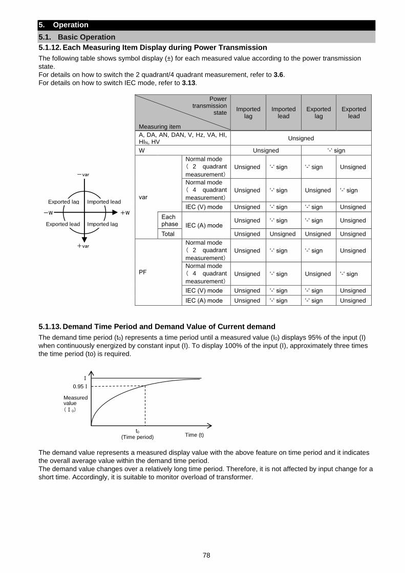
78
5. Operation
5.1. Basic Operation
5.1.12. Each Measuring Item Display during Power Transmission
The following table shows symbol display (±) for each measured value according to the power transmission
state.
For details on how to switch the 2 quadrant/4 quadrant measurement, refer to 3.6.
For details on how to switch IEC mode, refer to 3.13.
Power transmission
state Measuring item
Imported lag
Imported lead
Exported lag
Exported lead
A, DA, AN, DAN, V, Hz, VA, HI, HIN, HV
Unsigned
W Unsigned ‘-‘ sign
var
Normal mode
( 2 quadrant
measurement)
Unsigned ‘-‘ sign ‘-‘ sign Unsigned
Normal mode
( 4 quadrant
measurement)
Unsigned ‘-‘ sign Unsigned ‘-‘ sign
IEC (V) mode Unsigned ‘-‘ sign ‘-‘ sign Unsigned
Each phase IEC (A) mode
Unsigned ‘-‘ sign ‘-‘ sign Unsigned
Total Unsigned Unsigned Unsigned Unsigned
PF
Normal mode
( 2 quadrant
measurement)
Unsigned ‘-‘ sign ‘-‘ sign Unsigned
Normal mode
( 4 quadrant
measurement)
Unsigned ‘-‘ sign Unsigned ‘-‘ sign
IEC (V) mode Unsigned ‘-‘ sign ‘-‘ sign Unsigned
IEC (A) mode Unsigned ‘-‘ sign ‘-‘ sign Unsigned
5.1.13. Demand Time Period and Demand Value of Current demand
The demand time period (t0) represents a time period until a measured value (I0) displays 95% of the input (I)
when continuously energized by constant input (I). To display 100% of the input (I), approximately three times
the time period (to) is required.
The demand value represents a measured display value with the above feature on time period and it indicates
the overall average value within the demand time period.
The demand value changes over a relatively long time period. Therefore, it is not affected by input change for a
short time. Accordingly, it is suitable to monitor overload of transformer.
+W -W
+var
-var
Exported lag Imported lead
Exported lead Imported lag
Ⅰ
Measured value
Time (t)
(Ⅰ0)
t0 (Time period)
0.95Ⅰ
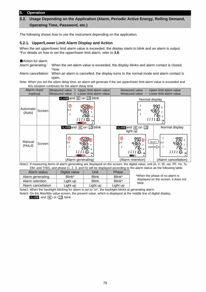
79
5. Operation
Usage Depending on the Application (Alarm, Periodic Active Energy, Rolling Demand,
Operating Time, Password, etc.)
The following shows how to use the instrument depending on the application.
5.2.1. Upper/Lower Limit Alarm Display and Action
When the set upper/lower limit alarm value is exceeded, the display starts to blink and an alarm is output.
*For details on how to set the upper/lower limit alarm, refer to 3.8.
Action for alarm
Alarm generating: When the set alarm value is exceeded, the display blinks and alarm contact is closed.
*Note
Alarm cancellation: When an alarm is cancelled, the display turns to the normal mode and alarm contact is
open.
Note: When you set the alarm delay time, an alarm will generate if the set upper/lower limit alarm value is exceeded and
this situation continues for the alarm delay time.
Alarm reset method
Measured value > Upper limit alarm value Measured value < Lower limit alarm value
Measured value < Upper limit alarm value Measured value > Lower limit alarm value
Automatic (Auto)
Screen
and or blink
Normal display
Manual (HoLd)
Screen
and or blink
(Alarm generating)
and or light up
(Alarm retention)
Normal display
(Alarm cancellation)
Note1: If measuring items of alarm generating are displayed on the screen, the digital value, unit (A, V, W, var, PF, Hz, %,
DM, and THD), and phase (1, 2, 3, and N) will be displayed according to the alarm status as the following table.
Alarm status Digital value Unit Phase
Alarm generating Blink* Blink Blink*
Alarm retention Light up Blink Blink*
Alarm cancellation Light up Light up Light up Note2: When the backlight blinking for alarm is set to ‘on’, the backlight blinks at generating alarm.
Note3: On the Max/Min value screen, the present value, which is displayed at the middle line of digital display,
, and or blink.
*When the phase of no alarm is displayed on the screen, it does not
blink.
RESET
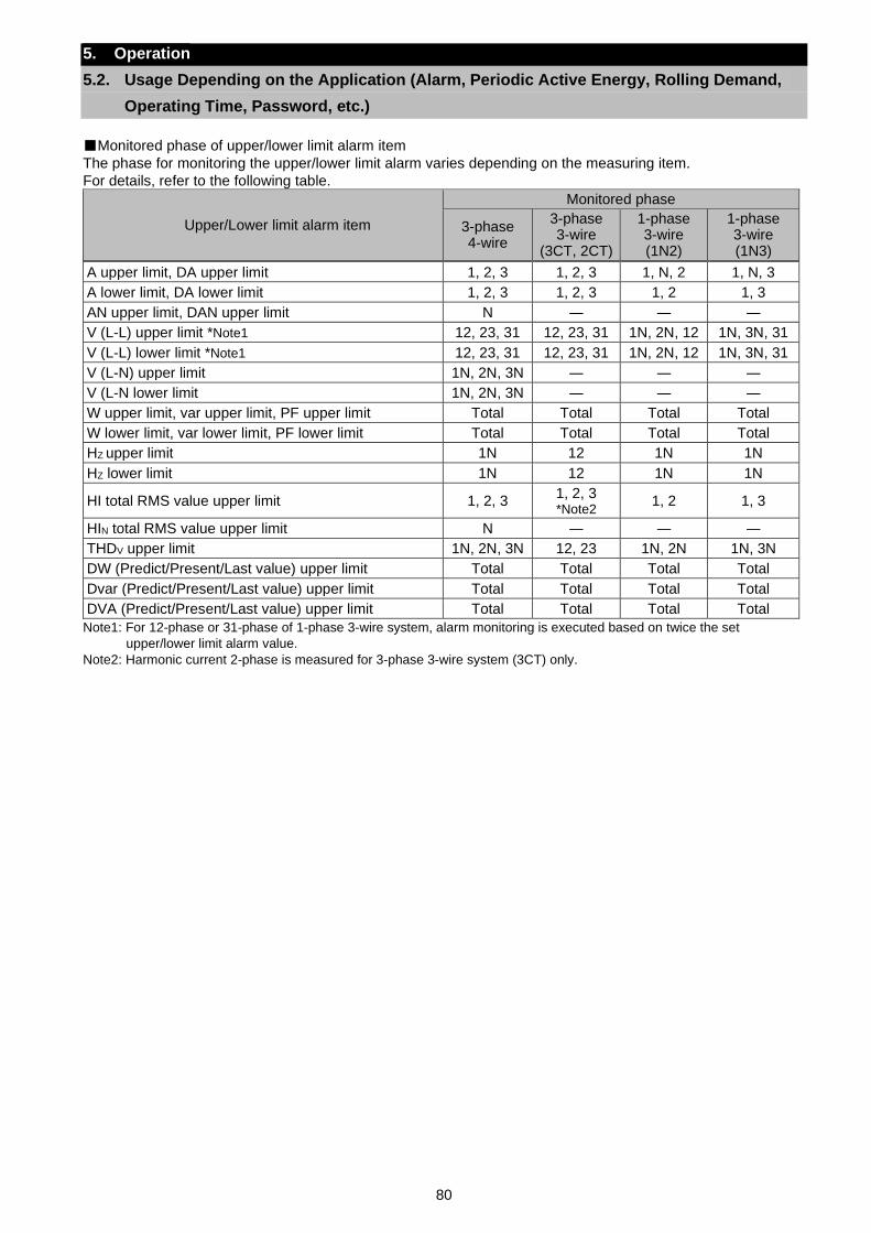
80
5. Operation
5.2. Usage Depending on the Application (Alarm, Periodic Active Energy, Rolling Demand,
Operating Time, Password, etc.)
Monitored phase of upper/lower limit alarm item
The phase for monitoring the upper/lower limit alarm varies depending on the measuring item.
For details, refer to the following table.
Upper/Lower limit alarm item
Monitored phase
3-phase 4-wire
3-phase 3-wire
(3CT, 2CT)
1-phase 3-wire (1N2)
1-phase 3-wire (1N3)
A upper limit, DA upper limit 1, 2, 3 1, 2, 3 1, N, 2 1, N, 3
A lower limit, DA lower limit 1, 2, 3 1, 2, 3 1, 2 1, 3
AN upper limit, DAN upper limit N ― ― ―
V (L-L) upper limit *Note1 12, 23, 31 12, 23, 31 1N, 2N, 12 1N, 3N, 31
V (L-L) lower limit *Note1 12, 23, 31 12, 23, 31 1N, 2N, 12 1N, 3N, 31
V (L-N) upper limit 1N, 2N, 3N ― ― ―
V (L-N lower limit 1N, 2N, 3N ― ― ―
W upper limit, var upper limit, PF upper limit Total Total Total Total
W lower limit, var lower limit, PF lower limit Total Total Total Total
HZ upper limit 1N 12 1N 1N
HZ lower limit 1N 12 1N 1N
HI total RMS value upper limit 1, 2, 3 1, 2, 3 *Note2
1, 2 1, 3
HIN total RMS value upper limit N ― ― ―
THDV upper limit 1N, 2N, 3N 12, 23 1N, 2N 1N, 3N
DW (Predict/Present/Last value) upper limit Total Total Total Total
Dvar (Predict/Present/Last value) upper limit Total Total Total Total
DVA (Predict/Present/Last value) upper limit Total Total Total Total
Note1: For 12-phase or 31-phase of 1-phase 3-wire system, alarm monitoring is executed based on twice the set
upper/lower limit alarm value.
Note2: Harmonic current 2-phase is measured for 3-phase 3-wire system (3CT) only.
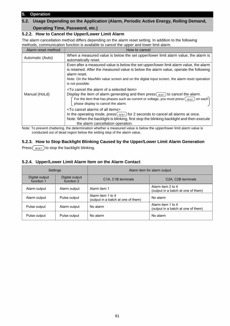
81
5. Operation
5.2. Usage Depending on the Application (Alarm, Periodic Active Energy, Rolling Demand,
Operating Time, Password, etc.)
5.2.2. How to Cancel the Upper/Lower Limit Alarm
The alarm cancellation method differs depending on the alarm reset setting. In addition to the following
methods, communication function is available to cancel the upper and lower limit alarm.
Alarm reset method How to cancel
Automatic (Auto) When a measured value is below the set upper/lower limit alarm value, the alarm is
automatically reset.
Manual (HoLd)
Even after a measured value is below the set upper/lower limit alarm value, the alarm
is retained. After the measured value is below the alarm value, operate the following
alarm reset.
Note: On the Max/Min value screen and on the digital input screen, the alarm reset operation
is not possible.
<To cancel the alarm of a selected item>
Display the item of alarm generating and then press to cancel the alarm.
For the item that has phases such as current or voltage, you must press on each
phase display to cancel the alarm.
<To cancel alarms of all items>
In the operating mode, press for 2 seconds to cancel all alarms at once.
Note: When the backlight is blinking, first stop the blinking backlight and then execute
the alarm cancellation operation.
Note: To prevent chattering, the determination whether a measured value is below the upper/lower limit alarm value is
conducted out of dead region below the setting step of the alarm value.
5.2.3. How to Stop Backlight Blinking Caused by the Upper/Lower Limit Alarm Generation
Press to stop the backlight blinking.
5.2.4. Upper/Lower Limit Alarm Item on the Alarm Contact
Settings Alarm item for alarm output
Digital output function 1
Digital output function 2
C1A, C1B terminals C2A, C2B terminals
Alarm output Alarm output Alarm item 1 Alarm item 2 to 4 (output in a batch at one of them)
Alarm output Pulse output Alarm item 1 to 4 (output in a batch at one of them)
No alarm
Pulse output Alarm output No alarm Alarm item 1 to 4 (output in a batch at one of them)
Pulse output Pulse output No alarm No alarm
RESET
RESET
RESET
RESET
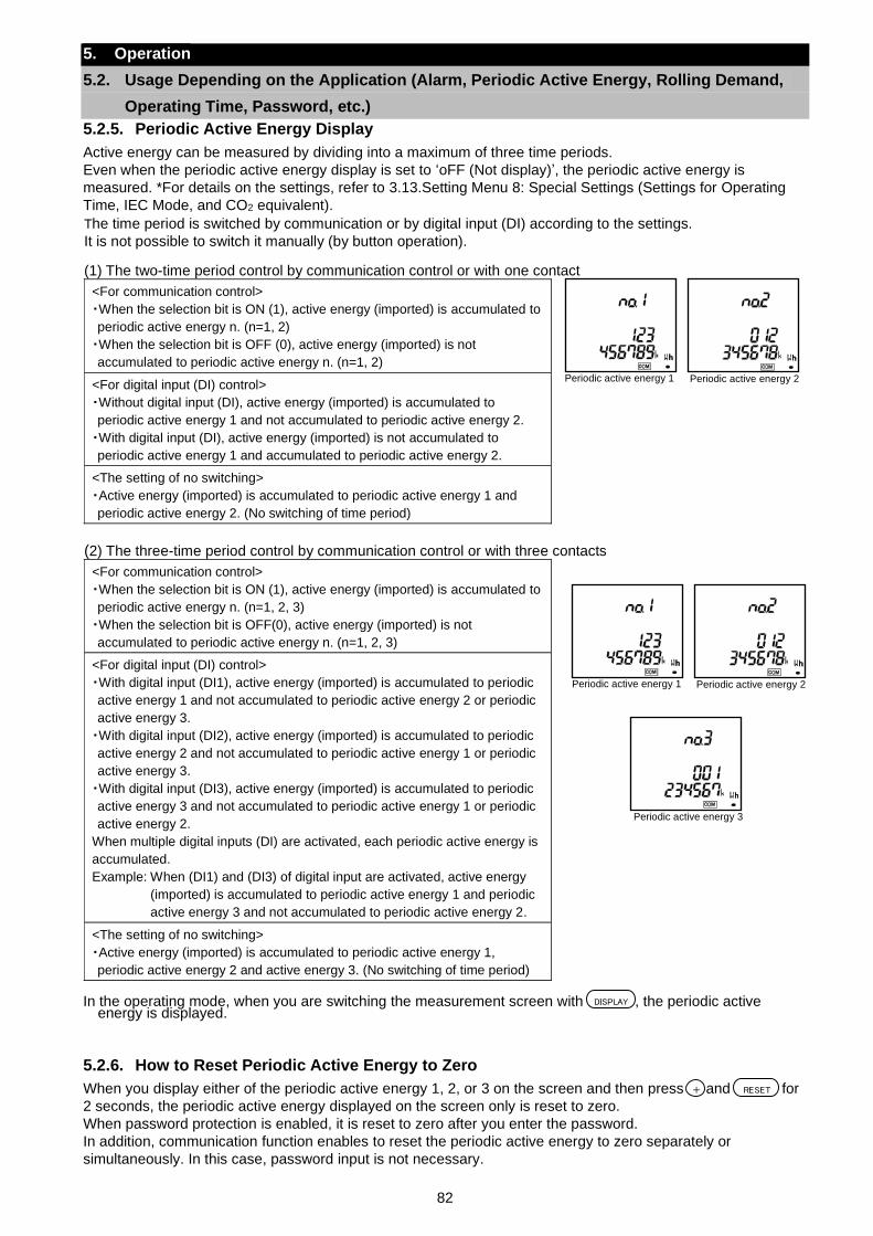
82
5. Operation
5.2. Usage Depending on the Application (Alarm, Periodic Active Energy, Rolling Demand,
Operating Time, Password, etc.)
5.2.5. Periodic Active Energy Display
Active energy can be measured by dividing into a maximum of three time periods.
Even when the periodic active energy display is set to ‘oFF (Not display)’, the periodic active energy is
measured. *For details on the settings, refer to 3.13.Setting Menu 8: Special Settings (Settings for Operating
Time, IEC Mode, and CO2 equivalent).
In the operating mode, when you are switching the measurement screen with , the periodic active
energy is displayed.
5.2.6. How to Reset Periodic Active Energy to Zero
When you display either of the periodic active energy 1, 2, or 3 on the screen and then press and for
2 seconds, the periodic active energy displayed on the screen only is reset to zero.
When password protection is enabled, it is reset to zero after you enter the password.
In addition, communication function enables to reset the periodic active energy to zero separately or
simultaneously. In this case, password input is not necessary.
The time period is switched by communication or by digital input (DI) according to the settings.
It is not possible to switch it manually (by button operation). (1) The two-time period control by communication control or with one contact
<For communication control>
・When the selection bit is ON (1), active energy (imported) is accumulated to
periodic active energy n. (n=1, 2)
・When the selection bit is OFF (0), active energy (imported) is not
accumulated to periodic active energy n. (n=1, 2)
<For digital input (DI) control>
・Without digital input (DI), active energy (imported) is accumulated to
periodic active energy 1 and not accumulated to periodic active energy 2.
・With digital input (DI), active energy (imported) is not accumulated to
periodic active energy 1 and accumulated to periodic active energy 2.
<The setting of no switching>
・Active energy (imported) is accumulated to periodic active energy 1 and
periodic active energy 2. (No switching of time period)
(2) The three-time period control by communication control or with three contacts
<For communication control>
・When the selection bit is ON (1), active energy (imported) is accumulated to
periodic active energy n. (n=1, 2, 3)
・When the selection bit is OFF(0), active energy (imported) is not
accumulated to periodic active energy n. (n=1, 2, 3)
<For digital input (DI) control>
・With digital input (DI1), active energy (imported) is accumulated to periodic
active energy 1 and not accumulated to periodic active energy 2 or periodic
active energy 3.
・With digital input (DI2), active energy (imported) is accumulated to periodic
active energy 2 and not accumulated to periodic active energy 1 or periodic
active energy 3.
・With digital input (DI3), active energy (imported) is accumulated to periodic
active energy 3 and not accumulated to periodic active energy 1 or periodic
active energy 2.
When multiple digital inputs (DI) are activated, each periodic active energy is
accumulated.
Example: When (DI1) and (DI3) of digital input are activated, active energy
(imported) is accumulated to periodic active energy 1 and periodic
active energy 3 and not accumulated to periodic active energy 2.
<The setting of no switching>
・Active energy (imported) is accumulated to periodic active energy 1,
periodic active energy 2 and active energy 3. (No switching of time period)
Periodic active energy 1 Periodic active energy 2
Periodic active energy 3
Periodic active energy 1 Periodic active energy 2
DISPLAY
RESET+
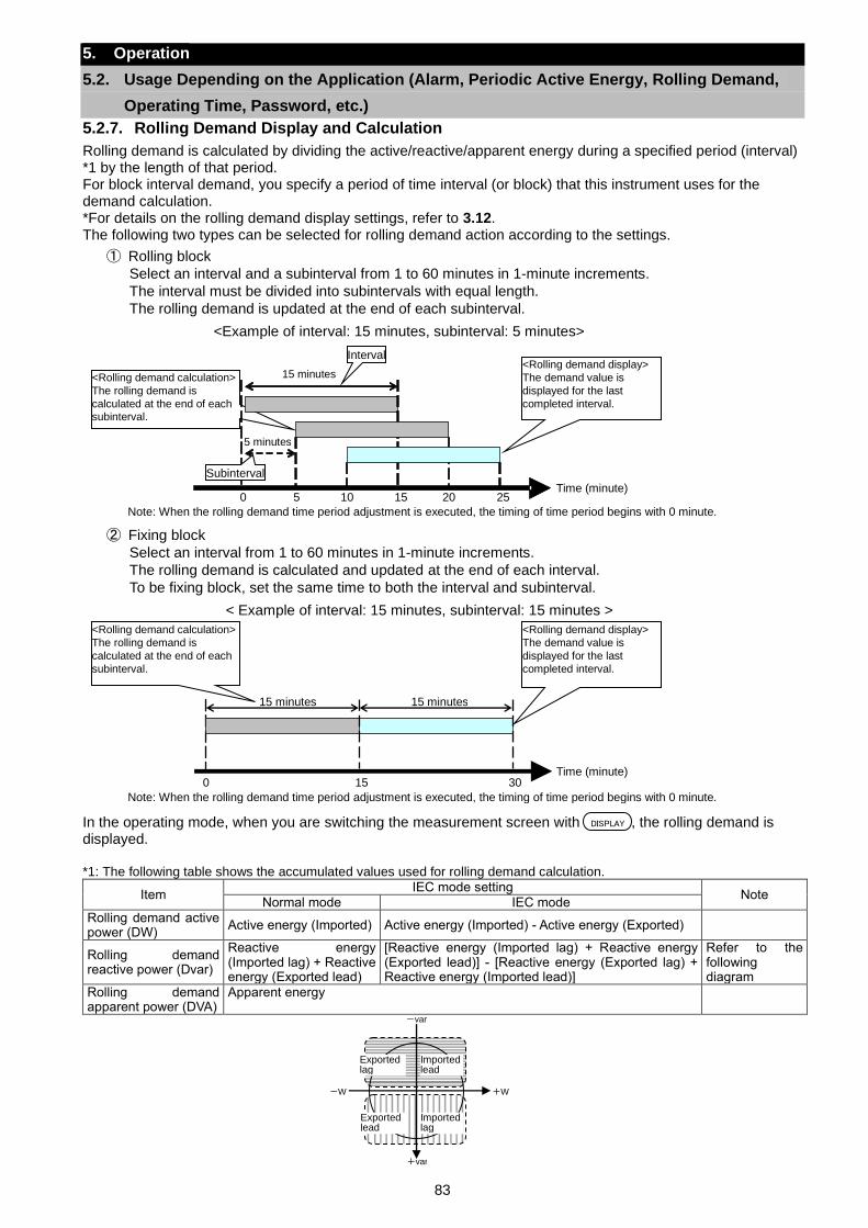
83
5. Operation
5.2. Usage Depending on the Application (Alarm, Periodic Active Energy, Rolling Demand,
Operating Time, Password, etc.)
5.2.7. Rolling Demand Display and Calculation
Rolling demand is calculated by dividing the active/reactive/apparent energy during a specified period (interval) *1 by the length of that period. For block interval demand, you specify a period of time interval (or block) that this instrument uses for the demand calculation. *For details on the rolling demand display settings, refer to 3.12. The following two types can be selected for rolling demand action according to the settings. In the operating mode, when you are switching the measurement screen with , the rolling demand is displayed. *1: The following table shows the accumulated values used for rolling demand calculation.
Item IEC mode setting
Note Normal mode IEC mode
Rolling demand active power (DW)
Active energy (Imported) Active energy (Imported) - Active energy (Exported)
Rolling demand reactive power (Dvar)
Reactive energy (Imported lag) + Reactive energy (Exported lead)
[Reactive energy (Imported lag) + Reactive energy (Exported lead)] - [Reactive energy (Exported lag) + Reactive energy (Imported lead)]
Refer to the following diagram
Rolling demand apparent power (DVA)
Apparent energy
① Rolling block
Select an interval and a subinterval from 1 to 60 minutes in 1-minute increments.
The interval must be divided into subintervals with equal length.
The rolling demand is updated at the end of each subinterval.
<Example of interval: 15 minutes, subinterval: 5 minutes>
② Fixing block
Select an interval from 1 to 60 minutes in 1-minute increments.
The rolling demand is calculated and updated at the end of each interval.
To be fixing block, set the same time to both the interval and subinterval.
< Example of interval: 15 minutes, subinterval: 15 minutes >
<Rolling demand calculation>
The rolling demand is
calculated at the end of each
subinterval.
<Rolling demand display>
The demand value is
displayed for the last
completed interval.
15 minutes
5 minutes
0 5 10 15 20 25 Time (minute)
<Rolling demand calculation>
The rolling demand is
calculated at the end of each
subinterval.
<Rolling demand display>
The demand value is
displayed for the last
completed interval.
15 minutes
15 minutes
0 15 30 Time (minute)
Note: When the rolling demand time period adjustment is executed, the timing of time period begins with 0 minute.
Note: When the rolling demand time period adjustment is executed, the timing of time period begins with 0 minute.
Interval
Subinterval
DISPLAY
+W -W
+var
-var
Exported lag
Imported lead
Exported lead
Imported lag
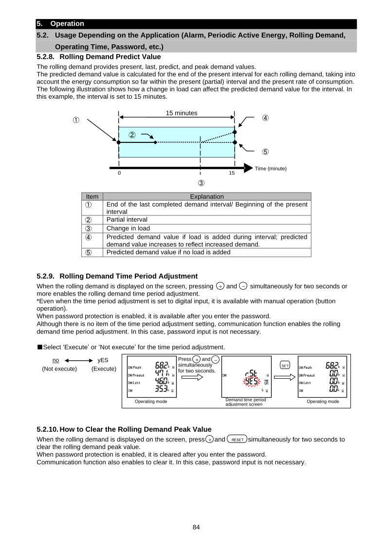
84
5. Operation
5.2. Usage Depending on the Application (Alarm, Periodic Active Energy, Rolling Demand,
Operating Time, Password, etc.)
5.2.8. Rolling Demand Predict Value
The rolling demand provides present, last, predict, and peak demand values. The predicted demand value is calculated for the end of the present interval for each rolling demand, taking into account the energy consumption so far within the present (partial) interval and the present rate of consumption. The following illustration shows how a change in load can affect the predicted demand value for the interval. In this example, the interval is set to 15 minutes.
Item Explanation
① End of the last completed demand interval/ Beginning of the present interval
② Partial interval
③ Change in load
④ Predicted demand value if load is added during interval; predicted demand value increases to reflect increased demand.
⑤ Predicted demand value if no load is added
5.2.9. Rolling Demand Time Period Adjustment
When the rolling demand is displayed on the screen, pressing and simultaneously for two seconds or more enables the rolling demand time period adjustment. *Even when the time period adjustment is set to digital input, it is available with manual operation (button operation).
When password protection is enabled, it is available after you enter the password.
Although there is no item of the time period adjustment setting, communication function enables the rolling
demand time period adjustment. In this case, password input is not necessary.
Select ‘Execute’ or ‘Not execute’ for the time period adjustment.
5.2.10. How to Clear the Rolling Demand Peak Value
When the rolling demand is displayed on the screen, press and simultaneously for two seconds to clear the rolling demand peak value.
When password protection is enabled, it is cleared after you enter the password.
Communication function also enables to clear it. In this case, password input is not necessary.
-
no yES
(Not execute) (Execute) SET
Demand time period adjustment screen
Operating mode Operating mode
Press and simultaneously for two seconds.
+ -
RESET
0 15 Time (minute)
① ④
⑤
15 minutes
③
②
+
+
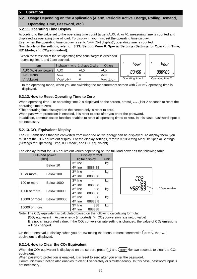
85
5. Operation
5.2. Usage Depending on the Application (Alarm, Periodic Active Energy, Rolling Demand,
Operating Time, Password, etc.)
5.2.11. Operating Time Display
According to the value set to the operating time count target (AUX, A, or V), measuring time is counted and
displayed as operating time of load. To display it, you must set the operating time display.
Even when the operating time display is set to ‘oFF (Not display)’, operating time is counted.
*For details on the settings, refer to 3.13. Setting Menu 8: Special Settings (Settings for Operating Time,
IEC Mode, and CO2 equivalent).
In the operating mode, when you are switching the measurement screen with , operating time is displayed.
5.2.12. How to Reset Operating Time to Zero
When operating time 1 or operating time 2 is displayed on the screen, press for 2 seconds to reset the
operating time to zero.
*The operating time displayed on the screen only is reset to zero.
When password protection is enabled, it is reset to zero after you enter the password.
In addition, communication function enables to reset all operating times to zero. In this case, password input is
not necessary.
5.2.13. CO2 Equivalent Display
The CO2 emissions that are converted from imported active energy can be displayed. To display them, you
must set the CO2 equivalent display. For the display settings, refer to 3.13Setting Menu 8: Special Settings
(Settings for Operating Time, IEC Mode, and CO2 equivalent).
The display format for CO2 equivalent varies depending on the full-load power as the following table.
Full-load power [kW]
Display format
Digital display Unit
Below 10 3rd line - kg
4th line 8888.88
10 or more Below 100 3rd line - kg
4th line 88888.8
100 or more Below 1000 3rd line - kg
4th line 888888
1000 or more Below 10000 3rd line 888 kg
4th line 8888.88
10000 or more Below 100000 3rd line 888 kg
4th line 88888.8
10000 or more 3rd line 888 kg
4th line 888888
Note: The CO2 equivalent is calculated based on the following calculating formula:
[CO2 equivalent = Active energy (imported) × CO2 conversion rate setup value]
It is not an integrated value. If the CO2 conversion rate setting is changed, the value of CO2 emissions will be changed.
On the present value display, when you are switching the measurement screen with , the CO2 equivalent is displayed.
5.2.14. How to Clear the CO2 Equivalent
When the CO2 equivalent is displayed on the screen, press and for two seconds to clear the CO2 equivalent. When password protection is enabled, it is reset to zero after you enter the password. Communication function also enables to clear it separately or simultaneously. In this case, password input is not necessary.
RESET
DISPLAY
Operating time 1
Operating time 2
When the threshold of the set operating time count target is exceeded, operating time 1 and 2 are counted.
Item 3-phase 4-wire 1-phase 2-wire Others
AUX (Auxiliary power) AUX AUX AUX
A (Current) AAVG A AAVG
V (Voltage) VAVG(L-N) V VAVG(L-L)
DISPLAY
CO2 equivalent
RESET+
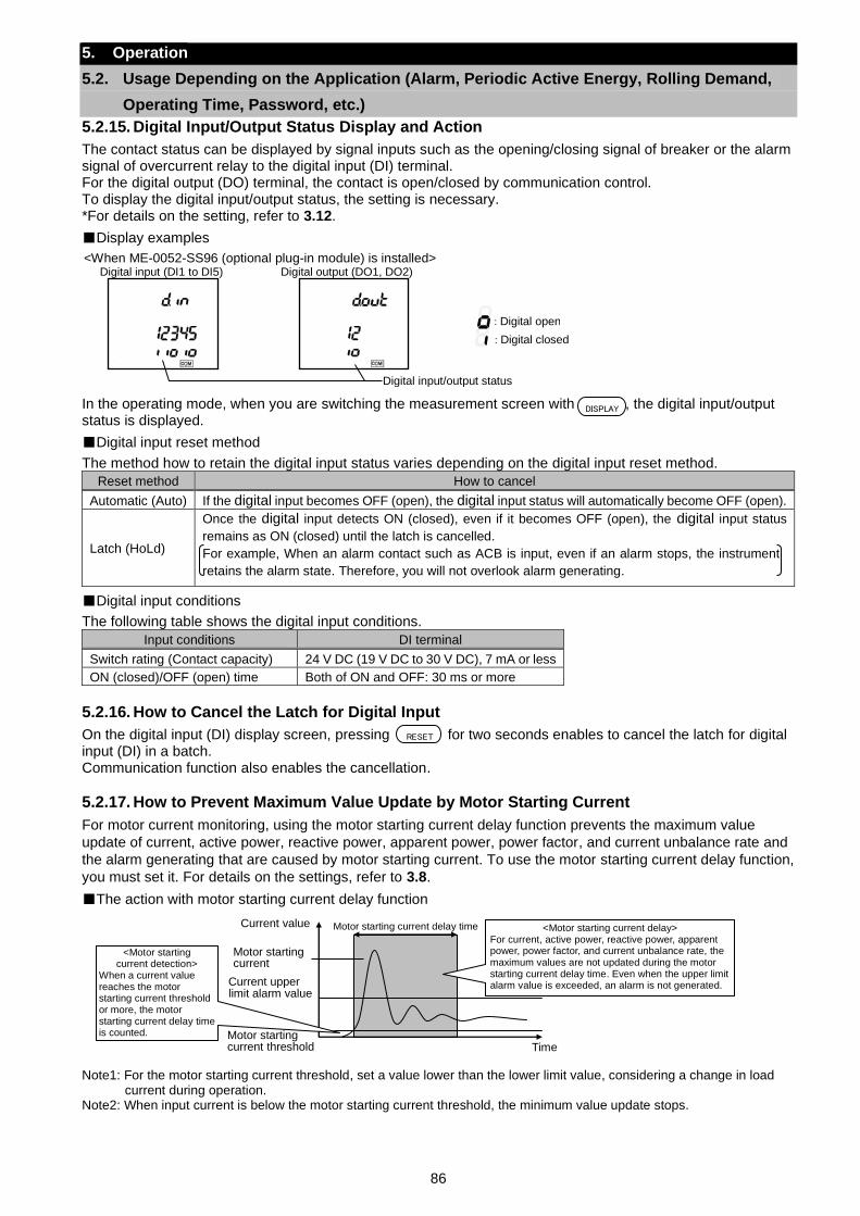
86
5. Operation
5.2. Usage Depending on the Application (Alarm, Periodic Active Energy, Rolling Demand,
Operating Time, Password, etc.)
5.2.15. Digital Input/Output Status Display and Action
The contact status can be displayed by signal inputs such as the opening/closing signal of breaker or the alarm signal of overcurrent relay to the digital input (DI) terminal. For the digital output (DO) terminal, the contact is open/closed by communication control. To display the digital input/output status, the setting is necessary. *For details on the setting, refer to 3.12.
Display examples
<When ME-0052-SS96 (optional plug-in module) is installed> Digital input (DI1 to DI5) Digital output (DO1, DO2)
: Digital closed
: Digital open
Digital input/output status
In the operating mode, when you are switching the measurement screen with , the digital input/output status is displayed.
Digital input reset method
The method how to retain the digital input status varies depending on the digital input reset method.
Reset method How to cancel
Automatic (Auto) If the digital input becomes OFF (open), the digital input status will automatically become OFF (open).
Latch (HoLd)
Once the digital input detects ON (closed), even if it becomes OFF (open), the digital input status
remains as ON (closed) until the latch is cancelled.
For example, When an alarm contact such as ACB is input, even if an alarm stops, the instrument
retains the alarm state. Therefore, you will not overlook alarm generating.
Digital input conditions
The following table shows the digital input conditions.
Input conditions DI terminal
Switch rating (Contact capacity) 24 V DC (19 V DC to 30 V DC), 7 mA or less
ON (closed)/OFF (open) time Both of ON and OFF: 30 ms or more
5.2.16. How to Cancel the Latch for Digital Input
On the digital input (DI) display screen, pressing for two seconds enables to cancel the latch for digital input (DI) in a batch. Communication function also enables the cancellation.
5.2.17. How to Prevent Maximum Value Update by Motor Starting Current
For motor current monitoring, using the motor starting current delay function prevents the maximum value
update of current, active power, reactive power, apparent power, power factor, and current unbalance rate and
the alarm generating that are caused by motor starting current. To use the motor starting current delay function,
you must set it. For details on the settings, refer to 3.8.
The action with motor starting current delay function
Note1: For the motor starting current threshold, set a value lower than the lower limit value, considering a change in load
current during operation. Note2: When input current is below the motor starting current threshold, the minimum value update stops.
DISPLAY
RESET
<Motor starting current detection>
When a current value reaches the motor starting current threshold or more, the motor starting current delay time is counted.
<Motor starting current delay> For current, active power, reactive power, apparent power, power factor, and current unbalance rate, the maximum values are not updated during the motor starting current delay time. Even when the upper limit alarm value is exceeded, an alarm is not generated.
Motor starting current delay time Current value
Time Motor starting current threshold
Current upper limit alarm value
Motor starting current
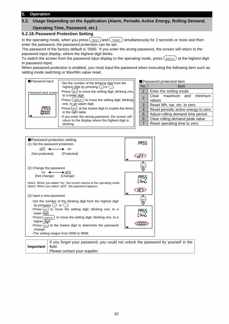
87
5. Operation
5.2. Usage Depending on the Application (Alarm, Periodic Active Energy, Rolling Demand,
Operating Time, Password, etc.)
5.2.18. Password Protection Setting
In the operating mode, when you press and simultaneously for 2 seconds or more and then
enter the password, the password protection can be set.
The password of the factory default is ‘0000.’ If you enter the wrong password, the screen will return to the
password input display, where the highest digit blinks.
To switch the screen from the password input display to the operating mode, press at the highest digit
in password input.
When password protection is enabled, you must input the password when executing the following item such as
setting mode switching or Max/Min value reset.
Password protected item
No. Item
1 Enter the setting mode
2 Clear maximum and minimum values
3 Reset Wh, var, etc. to zero
4 Reset periodic active energy to zero
5 Adjust rolling demand time period
6 Clear rolling demand peak value
7 Reset operating time to zero
RESET PHASE
Important If you forgot your password, you could not unlock the password by yourself in the field. Please contact your supplier.
Password input ・Set the number of the blinking digit from the
highest digit by pressing or .
・Press to move the setting digit, blinking one, to a lower digit.
・Press to move the setting digit, blinking one, to an upper digit.
・Press at the lowest digit to enable the items in the right table.
・If you enter the wrong password, the screen will return to the display where the highest digit is blinking.
+ -
DISPLAY
SET
SET
Password input screen
Password protection setting (1) Set the password protection.
(2) Change the password. Note1: When you select “no”, the screen returns to the operating mode. Note2: When you select “yES”, the password appears. (3) Input a new password.
oFF on
(Not protected) (Protected)
no yES (Not change) (Change)
・Set the number of the blinking digit from the highest digit
by pressing or .
・Press to move the setting digit, blinking one, to a
lower digit.
・Press to move the setting digit, blinking one, to a
higher digit.
・Press at the lowest digit to determine the password
change.
・The setting ranges from 0000 to 9999.
+ -
DISPLAY
SET
SET
SET
SET
DISPLAY
88
5. Operation
5.2. Usage Depending on the Application (Alarm, Periodic Active Energy, Rolling Demand,
Operating Time, Password, etc.)
5.2.19. Built-in Logging Function
This built-in logging function stores measured data as logging data in the internal non-volatile memory. The data to be stored as events occurred in this instrument are alarm data, the recorded time of the Max/Min value, and system log data. The stored data can be read from MODBUS RTU communication. To use this function, MODBUS RTU communication is required. It is not available with MODBUS TCP communication.
Built-in logging data type
The following table shows the logging data type used in this built-in logging function.
Type Details
Measurement data The measurement and time data are stored at the logging period you set.
The number of logging items
・Accumulated value data: 5 items
・Data other than accumulated value: 15 items Total: Max. 20 items
Internal memory logging period
・30 days (logging period: 15 minutes)
・60 days (logging period: 30 minutes)
・120 days (logging period: 60 minutes)
The storing timing is as follows:
Logging period Storing timing
15 min 00/15/30/45 minutes past every hour
30 min 00/30 minutes past every hour
60 min Every hour on the hour
Alarm data For each alarm item set at the upper/lower limit alarm item 1 to 4, the alarm item and its time data are stored when each event of alarm generating/cancellation or waiting for alarm cancellation occurs. Max. 100 records
The recorded time of the Max/Min value
The time data of when the Max or Min value is updated is stored. 1 record for each item
System log data The time data of when an event such as setting change occurs is stored. Max. 100 records
Note: The measurement data for logging has been grouped as LP01 and LP02 at this instrument side. Selecting the group determines the logging items. If you want to set a pattern other than LP01 or LP02, LP00 is available for selecting any logging items to set up.
Before using the built-in logging function The present time and built-in logging settings are required beforehand. For the present time setting and built-in logging setting, refer to 3.14 and 3.9 respectively.
How to read the built-in logging data The built-in logging data is read from MODBUS RTU communication. For the method, refer to Electronic Multi-Measuring Instrument ME Series MODBUS Interface specifications (Ref. No. LSPM-0075)
Caution
If the following settings are changed, the measurement data for built-in logging will be deleted. Before the change, output the logging data, check that the data is correctly stored, and execute the setting change. ・Setting change of phase wire system
・Built-in logging data clear
・Logging item change in LP00 of the built-in logging item pattern
・Setting change of the present time over the logging period When the present time is changed over the storing timing, a processing is executed to complement the measurement data of the corresponding time. Therefore, it is recommended to avoid the storing timing when the present time is changed. If the measurement data for built-in logging is monitored during the complemented processing, the data will be 0. After a while, execute it again.
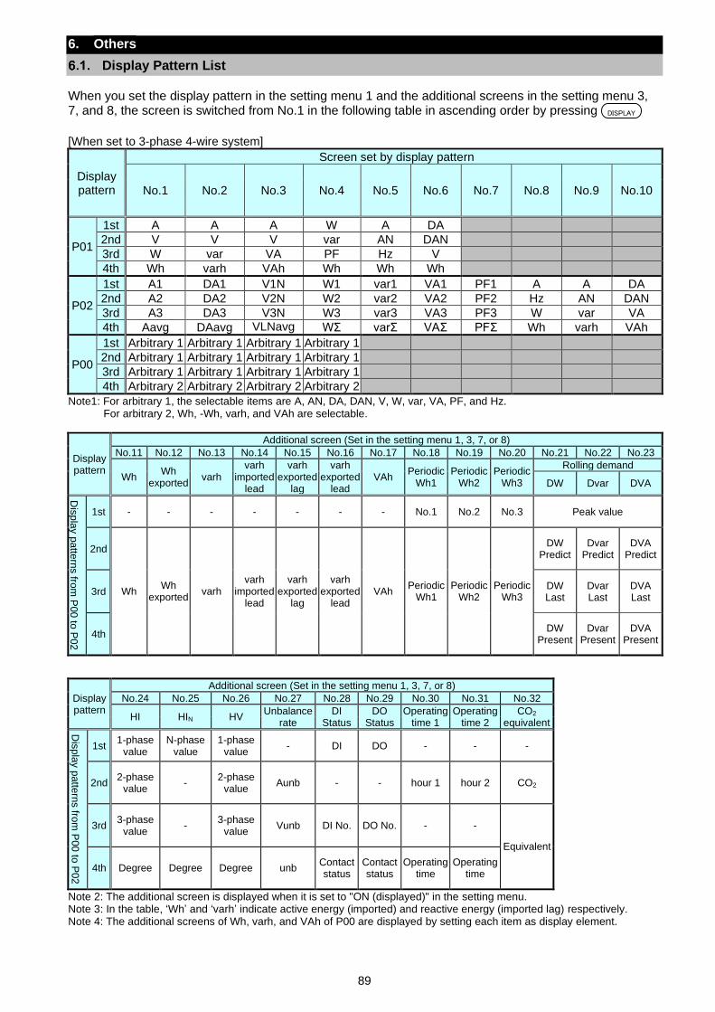
89
6. Others
Display Pattern List
When you set the display pattern in the setting menu 1 and the additional screens in the setting menu 3, 7, and 8, the screen is switched from No.1 in the following table in ascending order by pressing .
[When set to 3-phase 4-wire system]
Display pattern
Screen set by display pattern
No.1 No.2 No.3 No.4 No.5 No.6 No.7 No.8 No.9 No.10
P01
1st A A A W A DA
2nd V V V var AN DAN
3rd W var VA PF Hz V
4th Wh varh VAh Wh Wh Wh
P02
1st A1 DA1 V1N W1 var1 VA1 PF1 A A DA
2nd A2 DA2 V2N W2 var2 VA2 PF2 Hz AN DAN
3rd A3 DA3 V3N W3 var3 VA3 PF3 W var VA
4th Aavg DAavg VLNavg WΣ varΣ VAΣ PFΣ Wh varh VAh
P00
1st Arbitrary 1 Arbitrary 1 Arbitrary 1 Arbitrary 1
2nd Arbitrary 1 Arbitrary 1 Arbitrary 1 Arbitrary 1
3rd Arbitrary 1 Arbitrary 1 Arbitrary 1 Arbitrary 1
4th Arbitrary 2 Arbitrary 2 Arbitrary 2 Arbitrary 2
Note1: For arbitrary 1, the selectable items are A, AN, DA, DAN, V, W, var, VA, PF, and Hz. For arbitrary 2, Wh, -Wh, varh, and VAh are selectable.
Display pattern
Additional screen (Set in the setting menu 1, 3, 7, or 8)
No.11 No.12 No.13 No.14 No.15 No.16 No.17 No.18 No.19 No.20 No.21 No.22 No.23
Wh Wh
exported varh
varh imported
lead
varh exported
lag
varh exported
lead VAh
Periodic Wh1
Periodic Wh2
Periodic Wh3
Rolling demand
DW Dvar DVA
Dis
pla
y p
atte
rns fro
m P
00 to
P02
1st - - - - - - - No.1 No.2 No.3 Peak value
2nd
Wh Wh
exported varh
varh imported
lead
varh exported
lag
varh exported
lead VAh
Periodic Wh1
Periodic Wh2
Periodic Wh3
DW Predict
Dvar Predict
DVA Predict
3rd DW Last
Dvar Last
DVA Last
4th DW
Present Dvar
Present DVA
Present
Display pattern
Additional screen (Set in the setting menu 1, 3, 7, or 8)
No.24 No.25 No.26 No.27 No.28 No.29 No.30 No.31 No.32
HI HIN HV Unbalance
rate DI
Status DO
Status Operating
time 1 Operating
time 2 CO2
equivalent
Dis
pla
y p
atte
rns fro
m P
00 to
P02
1st 1-phase
value N-phase
value 1-phase
value - DI DO - - -
2nd 2-phase
value -
2-phase value
Aunb - - hour 1 hour 2 CO2
3rd 3-phase
value -
3-phase value
Vunb DI No. DO No. - -
Equivalent
4th Degree Degree Degree unb Contact status
Contact status
Operating time
Operating time
Note 2: The additional screen is displayed when it is set to "ON (displayed)" in the setting menu. Note 3: In the table, ‘Wh’ and ‘varh’ indicate active energy (imported) and reactive energy (imported lag) respectively. Note 4: The additional screens of Wh, varh, and VAh of P00 are displayed by setting each item as display element.
DISPLAY
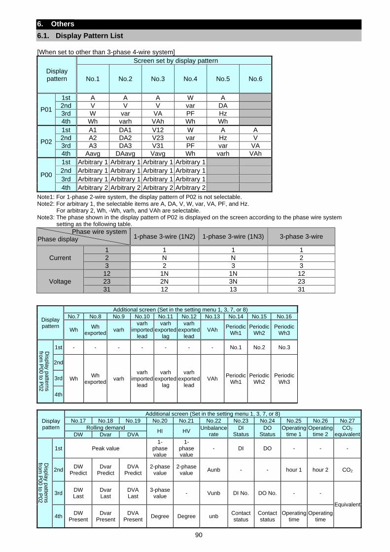
90
6. Others
6.1. Display Pattern List
[When set to other than 3-phase 4-wire system]
Display pattern
Screen set by display pattern
No.1 No.2 No.3 No.4 No.5 No.6
P01
1st A A A W A
2nd V V V var DA
3rd W var VA PF Hz
4th Wh varh VAh Wh Wh
P02
1st A1 DA1 V12 W A A
2nd A2 DA2 V23 var Hz V
3rd A3 DA3 V31 PF var VA
4th Aavg DAavg Vavg Wh varh VAh
P00
1st Arbitrary 1 Arbitrary 1 Arbitrary 1 Arbitrary 1
2nd Arbitrary 1 Arbitrary 1 Arbitrary 1 Arbitrary 1
3rd Arbitrary 1 Arbitrary 1 Arbitrary 1 Arbitrary 1
4th Arbitrary 2 Arbitrary 2 Arbitrary 2 Arbitrary 2
Note1: For 1-phase 2-wire system, the display pattern of P02 is not selectable. Note2: For arbitrary 1, the selectable items are A, DA, V, W, var, VA, PF, and Hz.
For arbitrary 2, Wh, -Wh, varh, and VAh are selectable. Note3: The phase shown in the display pattern of P02 is displayed on the screen according to the phase wire system
setting as the following table.
Phase wire system Phase display 1-phase 3-wire (1N2) 1-phase 3-wire (1N3) 3-phase 3-wire
Current
1 1 1 1
2 N N 2
3 2 3 3
Voltage
12 1N 1N 12
23 2N 3N 23
31 12 13 31
Display pattern
Additional screen (Set in the setting menu 1, 3, 7, or 8)
No.7 No.8 No.9 No.10 No.11 No.12 No.13 No.14 No.15 No.16
Wh Wh
exported varh
varh imported
lead
varh exported
lag
varh exported
lead VAh
Periodic Wh1
Periodic Wh2
Periodic Wh3
Dis
pla
y p
atte
rns
from
P00 to
P02
1st - - - - - - - No.1 No.2 No.3
2nd
Wh Wh
exported varh
varh imported
lead
varh exported
lag
varh exported
lead VAh
Periodic Wh1
Periodic Wh2
Periodic Wh3
3rd
4th
Display pattern
Additional screen (Set in the setting menu 1, 3, 7, or 8)
No.17 No.18 No.19 No.20 No.21 No.22 No.23 No.24 No.25 No.26 No.27
Rolling demand HI HV
Unbalance rate
DI Status
DO Status
Operating time 1
Operating time 2
CO2 equivalent DW Dvar DVA
Dis
pla
y p
atte
rns
from
P00 to
P02
1st Peak value 1-
phase value
1-phase value
- DI DO - - -
2nd DW
Predict Dvar
Predict DVA
Predict 2-phase
value 2-phase
value Aunb - - hour 1 hour 2 CO2
3rd DW Last
Dvar Last
DVA Last
3-phase value
- Vunb DI No. DO No. - -
Equivalent
4th DW
Present Dvar
Present DVA
Present Degree Degree unb
Contact status
Contact status
Operating time
Operating time

91
6. Others
6.1. Display Pattern List
Note4: The additional screen is displayed when it is set to "ON (displayed)" in the setting menu. Note5: In the table, ‘Wh’ and ‘varh’ indicate active energy (imported) and reactive energy (imported lag) respectively. Note6: The additional screens of Wh, varh, and VAh of P00 are displayed by setting each item as display element. Note7: The display of additional screens of No.20 and 21 in the above table varies depending on the setting of the phase
wire system as the following table. Phase wire system
Phase display 1-phase 2-wire 1-phase 3-wire 3-phase 3-wire _2CT 3-phase 3-wire _3CT
Harmonic current
1-phase value 〇 〇 〇 〇
2-phase value ― ― ― 〇
3-phase value ― 〇 〇 〇
Harmonic voltage 1-phase value 〇 〇 〇 〇
3-phase value ― 〇 〇 〇
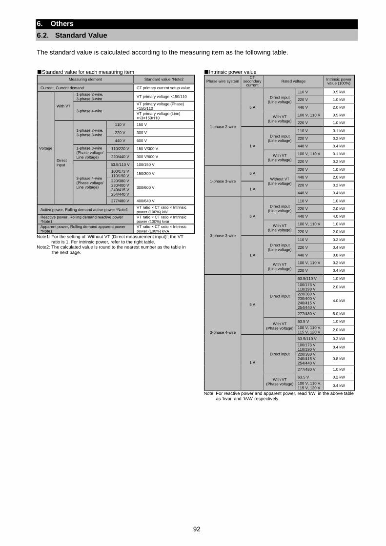
92
6. Others
Standard Value
The standard value is calculated according to the measuring item as the following table.
Standard value for each measuring item
Measuring element Standard value *Note2
Current, Current demand CT primary current setup value
Voltage
With VT
1-phase 2-wire, 3-phase 3-wire
VT primary voltage ×150/110
3-phase 4-wire
VT primary voltage (Phase) ×150/110
VT primary voltage (Line) ×√3×150/110
Direct input
1-phase 2-wire, 3-phase 3-wire
110 V 150 V
220 V 300 V
440 V 600 V
1-phase 3-wire (Phase voltage/ Line voltage)
110/220 V 150 V/300 V
220/440 V 300 V/600 V
3-phase 4-wire (Phase voltage/ Line voltage)
63.5/110 V 100/150 V
100/173 V 110/190 V
150/300 V
220/380 V 230/400 V 240/415 V 254/440 V
300/600 V
277/480 V 400/640 V
Active power, Rolling demand active power *Note1 VT ratio × CT ratio × Intrinsic power (100%) kW
Reactive power, Rolling demand reactive power *Note1
VT ratio × CT ratio × Intrinsic power (100%) kvar
Apparent power, Rolling demand apparent power *Note1
VT ratio × CT ratio × Intrinsic power (100%) kVA
Note1: For the setting of ‘Without VT (Direct measurement input)’, the VT ratio is 1. For intrinsic power, refer to the right table.
Note2: The calculated value is round to the nearest number as the table in the next page.
Intrinsic power value
Phase wire system CT
secondary current
Rated voltage Intrinsic power value (100%)
1-phase 2-wire
5 A
Direct input (Line voltage)
110 V 0.5 kW
220 V 1.0 kW
440 V 2.0 kW
With VT (Line voltage)
100 V, 110 V 0.5 kW
220 V 1.0 kW
1 A
Direct input (Line voltage)
110 V 0.1 kW
220 V 0.2 kW
440 V 0.4 kW
With VT (Line voltage)
100 V, 110 V 0.1 kW
220 V 0.2 kW
1-phase 3-wire
5 A
Without VT (Line voltage)
220 V 1.0 kW
440 V 2.0 kW
1 A 220 V 0.2 kW
440 V 0.4 kW
3-phase 3-wire
5 A
Direct input (Line voltage)
110 V 1.0 kW
220 V 2.0 kW
440 V 4.0 kW
With VT (Line voltage)
100 V, 110 V 1.0 kW
220 V 2.0 kW
1 A
Direct input (Line voltage)
110 V 0.2 kW
220 V 0.4 kW
440 V 0.8 kW
With VT (Line voltage)
100 V, 110 V 0.2 kW
220 V 0.4 kW
3-phase 4-wire
5 A
Direct input
63.5/110 V 1.0 kW
100/173 V 110/190 V
2.0 kW
220/380 V 230/400 V 240/415 V 254/440 V
4.0 kW
277/480 V 5.0 kW
With VT (Phase voltage)
63.5 V 1.0 kW
100 V, 110 V, 115 V, 120 V
2.0 kW
1 A
Direct input
63.5/110 V 0.2 kW
100/173 V 110/190 V
0.4 kW
220/380 V 240/415 V 254/440 V
0.8 kW
277/480 V 1.0 kW
With VT (Phase voltage)
63.5 V 0.2 kW
100 V, 110 V, 115 V, 120 V
0.4 kW
Note: For reactive power and apparent power, read ‘kW’ in the above table
as ‘kvar’ and ‘kVA’ respectively.
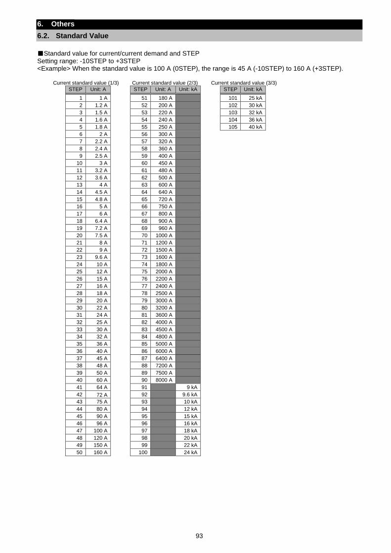
93
6. Others
6.2. Standard Value
Standard value for current/current demand and STEP Setting range: -10STEP to +3STEP <Example> When the standard value is 100 A (0STEP), the range is 45 A (-10STEP) to 160 A (+3STEP).
Current standard value (1/3) Current standard value (2/3) Current standard value (3/3)
STEP Unit: A STEP Unit: A Unit: kA STEP Unit: kA
1 1 A 51 180 A 101 25 kA
2 1.2 A 52 200 A 102 30 kA
3 1.5 A 53 220 A 103 32 kA
4 1.6 A 54 240 A 104 36 kA
5 1.8 A 55 250 A 105 40 kA
6 2 A 56 300 A
7 2.2 A 57 320 A
8 2.4 A 58 360 A
9 2.5 A 59 400 A
10 3 A 60 450 A
11 3.2 A 61 480 A
12 3.6 A 62 500 A
13 4 A 63 600 A
14 4.5 A 64 640 A
15 4.8 A 65 720 A
16 5 A 66 750 A
17 6 A 67 800 A
18 6.4 A 68 900 A
19 7.2 A 69 960 A
20 7.5 A 70 1000 A
21 8 A 71 1200 A
22 9 A 72 1500 A
23 9.6 A 73 1600 A
24 10 A 74 1800 A
25 12 A 75 2000 A
26 15 A 76 2200 A
27 16 A 77 2400 A
28 18 A 78 2500 A
29 20 A 79 3000 A
30 22 A 80 3200 A
31 24 A 81 3600 A
32 25 A 82 4000 A
33 30 A 83 4500 A
34 32 A 84 4800 A
35 36 A 85 5000 A
36 40 A 86 6000 A
37 45 A 87 6400 A
38 48 A 88 7200 A
39 50 A 89 7500 A
40 60 A 90 8000 A
41 64 A 91 9 kA
42 72 A 92 9.6 kA
43 75 A 93 10 kA
44 80 A 94 12 kA
45 90 A 95 15 kA
46 96 A 96 16 kA
47 100 A 97 18 kA
48 120 A 98 20 kA
49 150 A 99 22 kA
50 160 A 100 24 kA
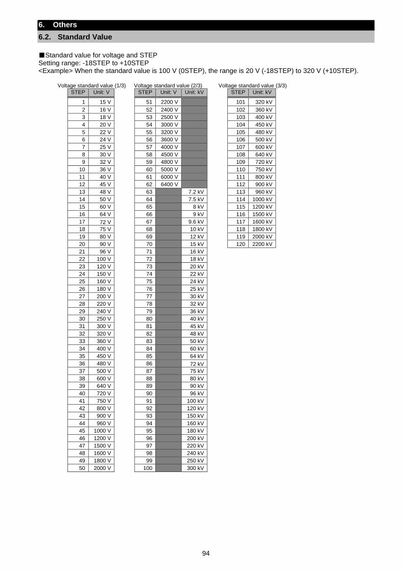
94
6. Others
6.2. Standard Value
Standard value for voltage and STEP Setting range: -18STEP to +10STEP <Example> When the standard value is 100 V (0STEP), the range is 20 V (-18STEP) to 320 V (+10STEP).
Voltage standard value (1/3) Voltage standard value (2/3) Voltage standard value (3/3)
STEP Unit: V STEP Unit: V Unit: kV STEP Unit: kV
1 15 V 51 2200 V 101 320 kV
2 16 V 52 2400 V 102 360 kV
3 18 V 53 2500 V 103 400 kV
4 20 V 54 3000 V 104 450 kV
5 22 V 55 3200 V 105 480 kV
6 24 V 56 3600 V 106 500 kV
7 25 V 57 4000 V 107 600 kV
8 30 V 58 4500 V 108 640 kV
9 32 V 59 4800 V 109 720 kV
10 36 V 60 5000 V 110 750 kV
11 40 V 61 6000 V 111 800 kV
12 45 V 62 6400 V 112 900 kV
13 48 V 63 7.2 kV 113 960 kV
14 50 V 64 7.5 kV 114 1000 kV
15 60 V 65 8 kV 115 1200 kV
16 64 V 66 9 kV 116 1500 kV
17 72 V 67 9.6 kV 117 1600 kV
18 75 V 68 10 kV 118 1800 kV
19 80 V 69 12 kV 119 2000 kV
20 90 V 70 15 kV 120 2200 kV
21 96 V 71 16 kV
22 100 V 72 18 kV
23 120 V 73 20 kV
24 150 V 74 22 kV
25 160 V 75 24 kV
26 180 V 76 25 kV
27 200 V 77 30 kV
28 220 V 78 32 kV
29 240 V 79 36 kV
30 250 V 80 40 kV
31 300 V 81 45 kV
32 320 V 82 48 kV
33 360 V 83 50 kV
34 400 V 84 60 kV
35 450 V 85 64 kV
36 480 V 86 72 kV
37 500 V 87 75 kV
38 600 V 88 80 kV
39 640 V 89 90 kV
40 720 V 90 96 kV
41 750 V 91 100 kV
42 800 V 92 120 kV
43 900 V 93 150 kV
44 960 V 94 160 kV
45 1000 V 95 180 kV
46 1200 V 96 200 kV
47 1500 V 97 220 kV
48 1600 V 98 240 kV
49 1800 V 99 250 kV
50 2000 V 100 300 kV
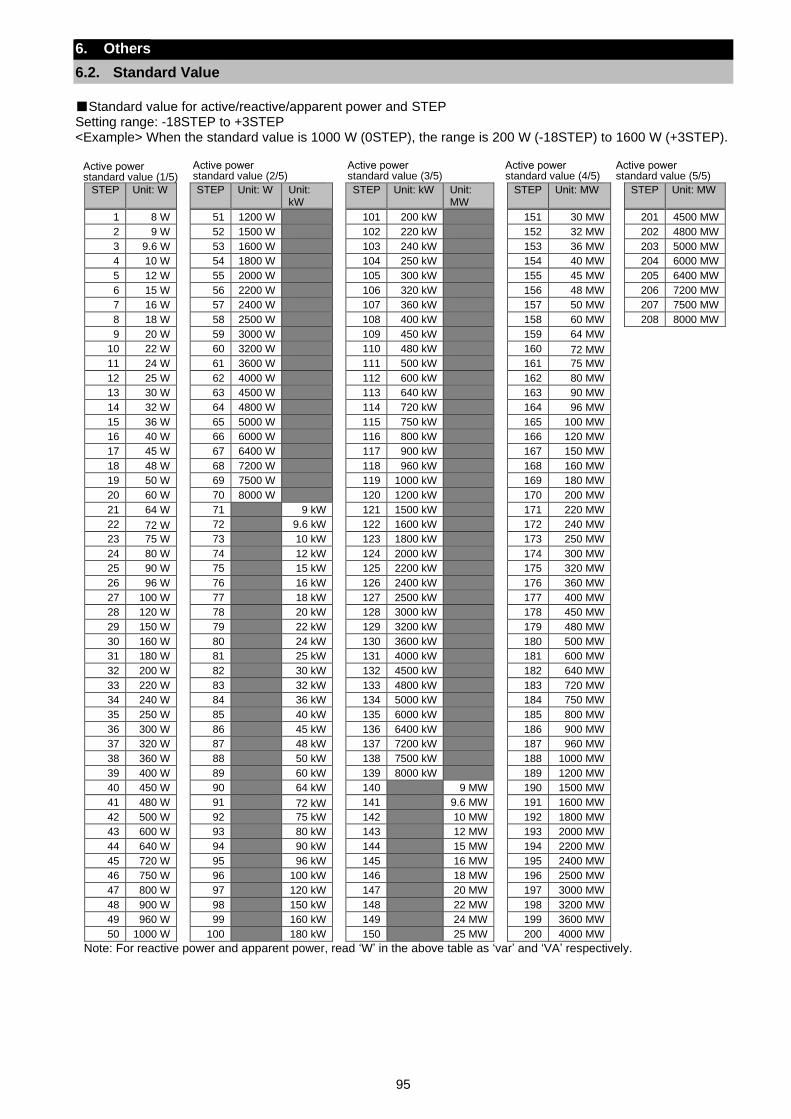
95
6. Others
6.2. Standard Value
Standard value for active/reactive/apparent power and STEP Setting range: -18STEP to +3STEP <Example> When the standard value is 1000 W (0STEP), the range is 200 W (-18STEP) to 1600 W (+3STEP).
STEP Unit: W
STEP Unit: W Unit: kW
STEP Unit: kW Unit: MW
STEP Unit: MW
STEP Unit: MW
1 8 W 51 1200 W 101 200 kW 151 30 MW 201 4500 MW
2 9 W 52 1500 W 102 220 kW 152 32 MW 202 4800 MW
3 9.6 W 53 1600 W 103 240 kW 153 36 MW 203 5000 MW
4 10 W 54 1800 W 104 250 kW 154 40 MW 204 6000 MW
5 12 W 55 2000 W 105 300 kW 155 45 MW 205 6400 MW
6 15 W 56 2200 W 106 320 kW 156 48 MW 206 7200 MW
7 16 W 57 2400 W 107 360 kW 157 50 MW 207 7500 MW
8 18 W 58 2500 W 108 400 kW 158 60 MW 208 8000 MW
9 20 W 59 3000 W 109 450 kW 159 64 MW
10 22 W 60 3200 W 110 480 kW 160 72 MW
11 24 W 61 3600 W 111 500 kW 161 75 MW
12 25 W 62 4000 W 112 600 kW 162 80 MW
13 30 W 63 4500 W 113 640 kW 163 90 MW
14 32 W 64 4800 W 114 720 kW 164 96 MW
15 36 W 65 5000 W 115 750 kW 165 100 MW
16 40 W 66 6000 W 116 800 kW 166 120 MW
17 45 W 67 6400 W 117 900 kW 167 150 MW
18 48 W 68 7200 W 118 960 kW 168 160 MW
19 50 W 69 7500 W 119 1000 kW 169 180 MW
20 60 W 70 8000 W 120 1200 kW 170 200 MW
21 64 W 71 9 kW 121 1500 kW 171 220 MW
22 72 W 72 9.6 kW 122 1600 kW 172 240 MW
23 75 W 73 10 kW 123 1800 kW 173 250 MW
24 80 W 74 12 kW 124 2000 kW 174 300 MW
25 90 W 75 15 kW 125 2200 kW 175 320 MW
26 96 W 76 16 kW 126 2400 kW 176 360 MW
27 100 W 77 18 kW 127 2500 kW 177 400 MW
28 120 W 78 20 kW 128 3000 kW 178 450 MW
29 150 W 79 22 kW 129 3200 kW 179 480 MW
30 160 W 80 24 kW 130 3600 kW 180 500 MW
31 180 W 81 25 kW 131 4000 kW 181 600 MW
32 200 W 82 30 kW 132 4500 kW 182 640 MW
33 220 W 83 32 kW 133 4800 kW 183 720 MW
34 240 W 84 36 kW 134 5000 kW 184 750 MW
35 250 W 85 40 kW 135 6000 kW 185 800 MW
36 300 W 86 45 kW 136 6400 kW 186 900 MW
37 320 W 87 48 kW 137 7200 kW 187 960 MW
38 360 W 88 50 kW 138 7500 kW 188 1000 MW
39 400 W 89 60 kW 139 8000 kW 189 1200 MW
40 450 W 90 64 kW 140 9 MW 190 1500 MW
41 480 W 91 72 kW 141 9.6 MW 191 1600 MW
42 500 W 92 75 kW 142 10 MW 192 1800 MW
43 600 W 93 80 kW 143 12 MW 193 2000 MW
44 640 W 94 90 kW 144 15 MW 194 2200 MW
45 720 W 95 96 kW 145 16 MW 195 2400 MW
46 750 W 96 100 kW 146 18 MW 196 2500 MW
47 800 W 97 120 kW 147 20 MW 197 3000 MW
48 900 W 98 150 kW 148 22 MW 198 3200 MW
49 960 W 99 160 kW 149 24 MW 199 3600 MW
50 1000 W 100 180 kW 150 25 MW 200 4000 MW
Note: For reactive power and apparent power, read ‘W’ in the above table as ‘var’ and ‘VA’ respectively.
Active power standard value (1/5)
Active power standard value (2/5)
Active power standard value (3/5)
Active power standard value (4/5)
Active power standard value (5/5)
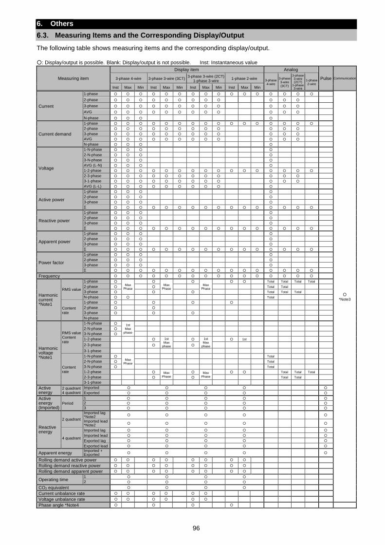
96
6. Others
Measuring Items and the Corresponding Display/Output
The following table shows measuring items and the corresponding display/output. : Display/output is possible. Blank: Display/output is not possible. Inst: Instantaneous value
Measuring item
Display item Analog
Pulse Communication 3-phase 4-wire 3-phase 3-wire (3CT) 3-phase 3-wire (2CT)
1-phase 3-wire 1-phase 2-wire
3-phase 4-wire
3-phase 3-wire (3CT)
3-phase 3-wire (2CT)
1-phase 3-wire
1-phase 2-wire
Inst Max Min Inst Max Min Inst Max Min Inst Max Min
Current
1-phase
*Note3
2-phase
3-phase
AVG
N-phase
Current demand
1-phase
2-phase
3-phase
AVG
N-phase
Voltage
1-N-phase
2-N-phase
3-N-phase
AVG (L-N)
1-2-phase
2-3-phase
3-1-phase
AVG (L-L)
Active power
1-phase
2-phase
3-phase
Σ
Reactive power
1-phase
2-phase
3-phase
Σ
Apparent power
1-phase
2-phase
3-phase
Σ
Power factor
1-phase
2-phase
3-phase
Σ
Frequency
Harmonic current *Note1
RMS value
1-phase Max
Phase
Max
Phase
Max
Phase
Total Total Total Total
2-phase Total Total
3-phase Total Total Total
N-phase Total
Content rate
1-phase
2-phase
3-phase
N-phase
Harmonic voltage *Note1
RMS value Content rate
1-N-phase 1st Max
phase
2-N-phase
3-N-phase
1-2-phase 1st Max
phase
1st Max
phase
1st
2-3-phase
3-1-phase
Content rate
1-N-phase Max
Phase
Total
2-N-phase Total
3-N-phase Total
1-2-phase Max Phase
Max Phase
Total Total Total
2-3-phase Total Total
3-1-phase
Active energy
2 quadrant 4 quadrant
Imported
Exported
Active energy (Imported)
Period
1
2
3
Reactive energy
2 quadrant
Imported lag *Note2
Imported lead *Note2
4 quadrant
Imported lag
Imported lead
Exported lag
Exported lead
Apparent energy Imported + Exported
Rolling demand active power
Rolling demand reactive power
Rolling demand apparent power
Operating time 1
2
CO2 equivalent
Current unbalance rate
Voltage unbalance rate
Phase angle *Note4

97
6. Others
6.3. Measuring Items and the Corresponding Display/Output
Note1: Each harmonic degree represents the odd degrees of the 1st to 31st RMS value and the 3rd to 31st content rate. Note2: The imported lag and imported lead include the exported lead and exported lag respectively. Note3: For the measuring items monitored by communication function, refer to the specifications of each communication function. Note4: Phase angle can be measured only with the support function for determining incorrect wiring. Note5: For 1-phase 3-wire system, the phases of measuring items are read as the following table.
Phase wire system 1-phase 2-phase 3-phase 12-phase 23-phase 31-phase
1-phase 3-wire (1N2) 1-phase N-phase 2-phase 1N-phase 2N-phase 12-phase
1-phase 3-wire (1N3) 1-phase N-phase 3-phase 1N-phase 3N-phase 13-phase
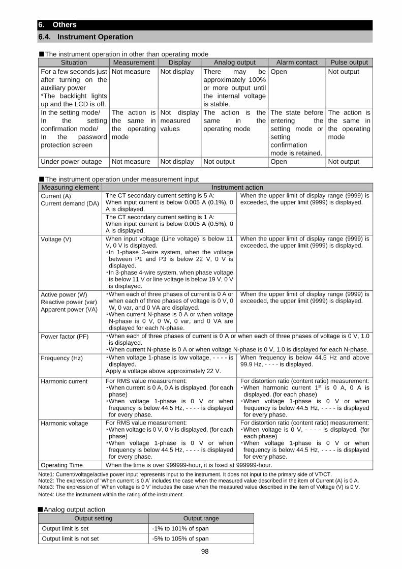
98
6. Others
Instrument Operation
The instrument operation in other than operating mode
Situation Measurement Display Analog output Alarm contact Pulse output
For a few seconds just
after turning on the
auxiliary power
*The backlight lights
up and the LCD is off.
Not measure Not display There may be
approximately 100%
or more output until
the internal voltage
is stable.
Open Not output
In the setting mode/
In the setting
confirmation mode/
In the password
protection screen
The action is
the same in
the operating
mode
Not display
measured
values
The action is the
same in the
operating mode
The state before
entering the
setting mode or
setting
confirmation
mode is retained.
The action is
the same in
the operating
mode
Under power outage Not measure Not display Not output Open Not output
The instrument operation under measurement input
Measuring element Instrument action
Current (A)
Current demand (DA)
The CT secondary current setting is 5 A: When input current is below 0.005 A (0.1%), 0 A is displayed.
When the upper limit of display range (9999) is exceeded, the upper limit (9999) is displayed.
The CT secondary current setting is 1 A: When input current is below 0.005 A (0.5%), 0 A is displayed.
Voltage (V) When input voltage (Line voltage) is below 11 V, 0 V is displayed. ・In 1-phase 3-wire system, when the voltage between P1 and P3 is below 22 V, 0 V is displayed. ・In 3-phase 4-wire system, when phase voltage is below 11 V or line voltage is below 19 V, 0 V is displayed.
When the upper limit of display range (9999) is exceeded, the upper limit (9999) is displayed.
Active power (W)
Reactive power (var)
Apparent power (VA)
・When each of three phases of current is 0 A or when each of three phases of voltage is 0 V, 0 W, 0 var, and 0 VA are displayed. ・When current N-phase is 0 A or when voltage N-phase is 0 V, 0 W, 0 var, and 0 VA are displayed for each N-phase.
When the upper limit of display range (9999) is exceeded, the upper limit (9999) is displayed.
Power factor (PF) ・When each of three phases of current is 0 A or when each of three phases of voltage is 0 V, 1.0 is displayed. ・When current N-phase is 0 A or when voltage N-phase is 0 V, 1.0 is displayed for each N-phase.
Frequency (Hz) ・When voltage 1-phase is low voltage, - - - - is displayed.
Apply a voltage above approximately 22 V.
When frequency is below 44.5 Hz and above 99.9 Hz, - - - - is displayed.
Harmonic current For RMS value measurement: ・When current is 0 A, 0 A is displayed. (for each phase) ・When voltage 1-phase is 0 V or when frequency is below 44.5 Hz, - - - - is displayed for every phase.
For distortion ratio (content ratio) measurement: ・When harmonic current 1st is 0 A, 0 A is displayed. (for each phase) ・When voltage 1-phase is 0 V or when frequency is below 44.5 Hz, - - - - is displayed for every phase.
Harmonic voltage For RMS value measurement: ・When voltage is 0 V, 0 V is displayed. (for each phase) ・When voltage 1-phase is 0 V or when frequency is below 44.5 Hz, - - - - is displayed for every phase.
For distortion ratio (content ratio) measurement: ・When voltage is 0 V, - - - - is displayed. (for each phase) ・When voltage 1-phase is 0 V or when frequency is below 44.5 Hz, - - - - is displayed for every phase.
Operating Time When the time is over 999999-hour, it is fixed at 999999-hour.
Note1: Current/voltage/active power input represents input to the instrument. It does not input to the primary side of VT/CT. Note2: The expression of ‘When current is 0 A’ includes the case when the measured value described in the item of Current (A) is 0 A. Note3: The expression of ‘When voltage is 0 V’ includes the case when the measured value described in the item of Voltage (V) is 0 V.
Note4: Use the instrument within the rating of the instrument.
Analog output action
Output setting Output range
Output limit is set -1% to 101% of span
Output limit is not set -5% to 105% of span
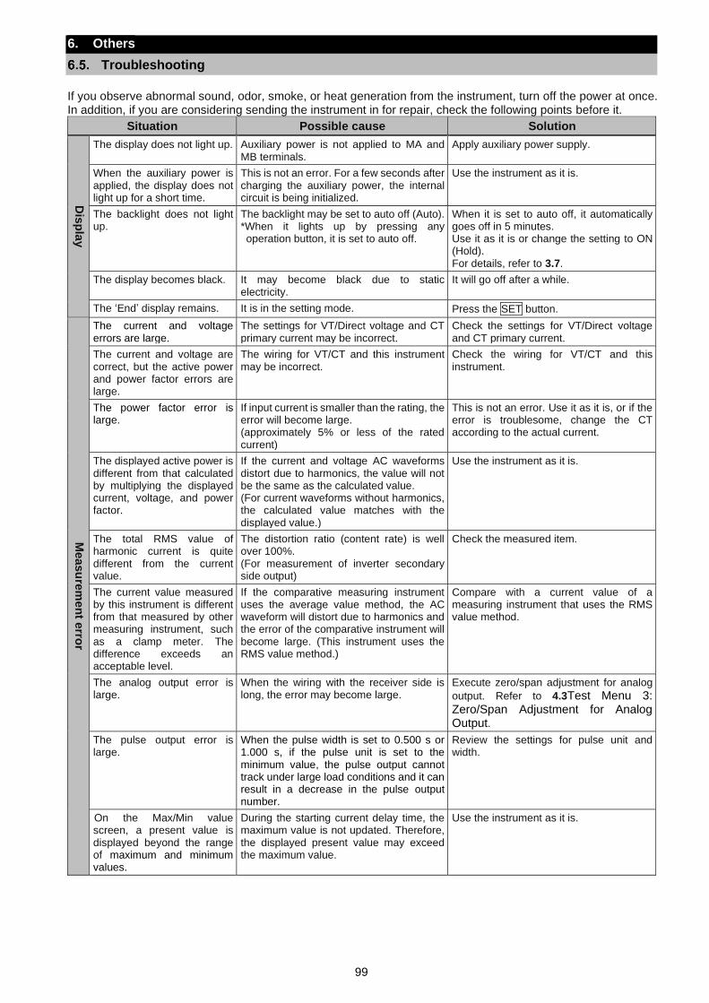
99
6. Others
Troubleshooting
If you observe abnormal sound, odor, smoke, or heat generation from the instrument, turn off the power at once. In addition, if you are considering sending the instrument in for repair, check the following points before it.
Situation Possible cause Solution
Dis
pla
y
The display does not light up. Auxiliary power is not applied to MA and MB terminals.
Apply auxiliary power supply.
When the auxiliary power is applied, the display does not light up for a short time.
This is not an error. For a few seconds after charging the auxiliary power, the internal circuit is being initialized.
Use the instrument as it is.
The backlight does not light up.
The backlight may be set to auto off (Auto). *When it lights up by pressing any operation button, it is set to auto off.
When it is set to auto off, it automatically goes off in 5 minutes. Use it as it is or change the setting to ON (Hold). For details, refer to 3.7.
The display becomes black. It may become black due to static electricity.
It will go off after a while.
The ‘End’ display remains. It is in the setting mode. Press the SET button.
Measu
rem
en
t erro
r
The current and voltage errors are large.
The settings for VT/Direct voltage and CT primary current may be incorrect.
Check the settings for VT/Direct voltage and CT primary current.
The current and voltage are correct, but the active power and power factor errors are large.
The wiring for VT/CT and this instrument may be incorrect.
Check the wiring for VT/CT and this instrument.
The power factor error is large.
If input current is smaller than the rating, the error will become large. (approximately 5% or less of the rated current)
This is not an error. Use it as it is, or if the error is troublesome, change the CT according to the actual current.
The displayed active power is different from that calculated by multiplying the displayed current, voltage, and power factor.
If the current and voltage AC waveforms distort due to harmonics, the value will not be the same as the calculated value. (For current waveforms without harmonics, the calculated value matches with the displayed value.)
Use the instrument as it is.
The total RMS value of harmonic current is quite different from the current value.
The distortion ratio (content rate) is well over 100%. (For measurement of inverter secondary side output)
Check the measured item.
The current value measured by this instrument is different from that measured by other measuring instrument, such as a clamp meter. The difference exceeds an acceptable level.
If the comparative measuring instrument uses the average value method, the AC waveform will distort due to harmonics and the error of the comparative instrument will become large. (This instrument uses the RMS value method.)
Compare with a current value of a measuring instrument that uses the RMS value method.
The analog output error is large.
When the wiring with the receiver side is long, the error may become large.
Execute zero/span adjustment for analog
output. Refer to 4.3Test Menu 3: Zero/Span Adjustment for Analog Output.
The pulse output error is large.
When the pulse width is set to 0.500 s or 1.000 s, if the pulse unit is set to the minimum value, the pulse output cannot track under large load conditions and it can result in a decrease in the pulse output number.
Review the settings for pulse unit and width.
On the Max/Min value screen, a present value is displayed beyond the range of maximum and minimum values.
During the starting current delay time, the maximum value is not updated. Therefore, the displayed present value may exceed the maximum value.
Use the instrument as it is.
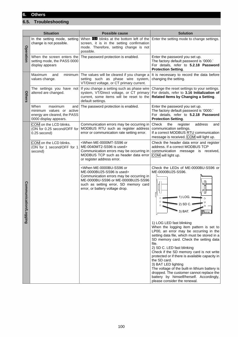
100
6. Others
6.5. Troubleshooting
Situation Possible cause Solution
Op
era
tion
In the setting mode, setting change is not possible.
When blinks at the bottom left of the screen, it is in the setting confirmation mode. Therefore, setting change is not possible.
Enter the setting mode to change settings.
When the screen enters the setting mode, the PASS 0000 display appears
The password protection is enabled. Enter the password you set up. The factory default password is ‘0000.’ For details, refer to 5.2.18 Password Protection Setting.
Oth
ers
Maximum and minimum values change.
The values will be cleared if you change a setting such as phase wire system, VT/Direct voltage, or CT primary current.
It is necessary to record the data before changing the setting.
The settings you have not altered are changed.
If you change a setting such as phase wire system, VT/Direct voltage, or CT primary current, some items will be reset to the default settings.
Change the reset settings to your settings. For details, refer to 3.16 Initialization of Related Items by Changing a Setting.
When maximum and minimum values or active energy are cleared, the PASS 0000 display appears.
The password protection is enabled. Enter the password you set up. The factory default password is ‘0000.’ For details, refer to 5.2.18 Password Protection Setting.
Co
mm
un
ica
tion
/Lo
gg
ing
COM on the LCD blinks.
(ON for 0.25 second/OFF for 0.25 second)
Communication errors may be occurring in MODBUS RTU such as register address error or communication rate setting error.
Check the register address and communication settings. If a correct MODBUS RTU communication
message is received, COM will light up.
COM on the LCD blinks.
(ON for 1 second/OFF for 1 second)
<When ME-0000MT-SS96 or ME-0040MT2-SS96 is used> Communication errors may be occurring in MODBUS TCP such as header data error or register address error.
Check the header data error and register address. If a correct MODBUS TCP communication message is received,
COM will light up.
<When ME-0000BU-SS96 or ME-0000BU25-SS96 is used> Communication errors may be occurring in ME-0000BU-SS96 or ME-0000BU25-SS96 such as setting error, SD memory card error, or battery voltage drop.
Check the LEDs of ME-0000BU-SS96 or ME-0000BU25-SS96.
1) LOG LED fast blinking When the logging item pattern is set to LP00, an error may be occurring in the setting data file, which must be stored in a SD memory card. Check the setting data file. 2) SD C. LED fast blinking Check if the SD memory card is not write protected or if there is available capacity in the SD card. 3) BAT LED lighting The voltage of the built-in lithium battery is dropped. The customer cannot replace the battery by himself/herself. Accordingly, please consider the renewal.
1) LOG.
2) SD C.
3) BAT.
101
6. Others
6.5. Troubleshooting
Situation Possible cause Solution
Co
mm
un
ica
tion
/Lo
gg
ing
Although LOG on the LCD
lights up, the clock status goes off.
The present time is not set. Set the present time, and the clock status will light up. After this instrument restarts by applying the auxiliary power or by shifting from the test mode to the operating mode, the present time setting is necessary. For details, refer to 3.14Setting Menu CL: Present Time Settings.
MODBUS TCP communication is not possible. (When ME-0040MT2-SS96 is installed) In addition, the 10/100 LED and LINK/ACT LED are all ON.
ME-0040MT2-SS96 is only applicable to this instrument with firmware version 01.01 or later. The firmware version can be confirmed in the setting menu 4.2. Refer to 3.7Setting Menu 4: LCD Settings (Settings for Model Display, Version Display, Backlight, and Display Update Time).
Use ME-0040MT2-SS96 and this instrument with firmware version 01.01 or later in combination.
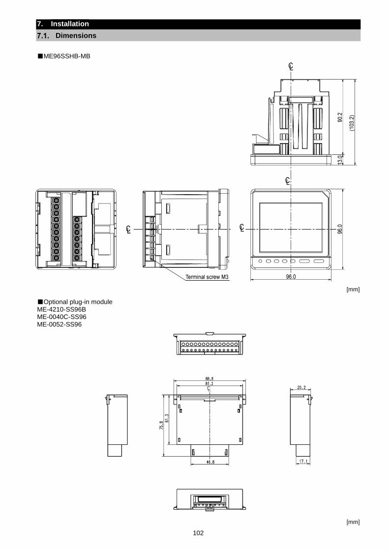
102
7. Installation
Dimensions
ME96SSHB-MB
[mm]
Optional plug-in module ME-4210-SS96B ME-0040C-SS96 ME-0052-SS96
[mm]
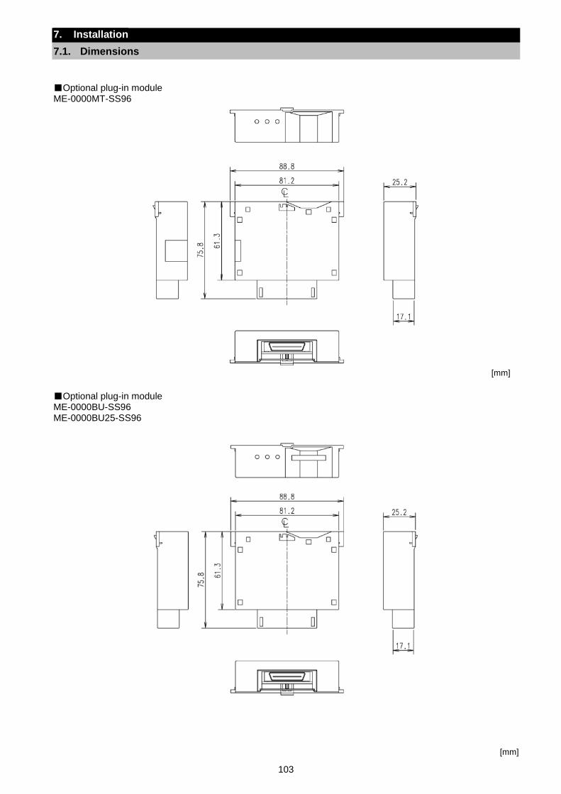
103
7. Installation
7.1. Dimensions
Optional plug-in module ME-0000MT-SS96
[mm]
Optional plug-in module ME-0000BU-SS96 ME-0000BU25-SS96
[mm]
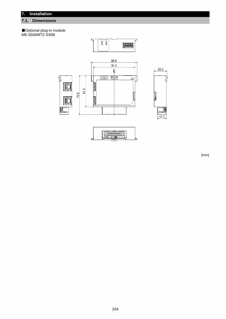
104
7. Installation
7.1. Dimensions
Optional plug-in module ME-0040MT2-SS96
[mm]
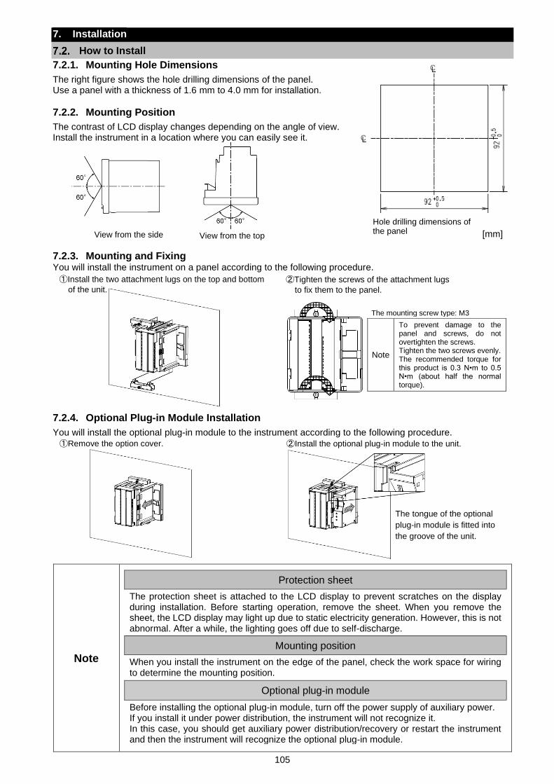
105
7. Installation
How to Install
7.2.1. Mounting Hole Dimensions
The right figure shows the hole drilling dimensions of the panel. Use a panel with a thickness of 1.6 mm to 4.0 mm for installation.
7.2.2. Mounting Position
The contrast of LCD display changes depending on the angle of view. Install the instrument in a location where you can easily see it.
[mm]
7.2.3. Mounting and Fixing You will install the instrument on a panel according to the following procedure.
7.2.4. Optional Plug-in Module Installation
You will install the optional plug-in module to the instrument according to the following procedure.
Note
Protection sheet
The protection sheet is attached to the LCD display to prevent scratches on the display during installation. Before starting operation, remove the sheet. When you remove the sheet, the LCD display may light up due to static electricity generation. However, this is not abnormal. After a while, the lighting goes off due to self-discharge.
Mounting position
When you install the instrument on the edge of the panel, check the work space for wiring to determine the mounting position.
Optional plug-in module
Before installing the optional plug-in module, turn off the power supply of auxiliary power. If you install it under power distribution, the instrument will not recognize it. In this case, you should get auxiliary power distribution/recovery or restart the instrument and then the instrument will recognize the optional plug-in module.
View from the side View from the top
①Install the two attachment lugs on the top and bottom
of the unit.
The mounting screw type: M3
Note
To prevent damage to the panel and screws, do not overtighten the screws. Tighten the two screws evenly. The recommended torque for this product is 0.3 N•m to 0.5 N•m (about half the normal torque).
②Tighten the screws of the attachment lugs
to fix them to the panel.
Hole drilling dimensions of the panel
①Remove the option cover. ②Install the optional plug-in module to the unit.
The tongue of the optional
plug-in module is fitted into
the groove of the unit.
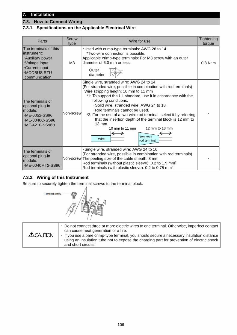
106
7. Installation
How to Connect Wiring
7.3.1. Specifications on the Applicable Electrical Wire
Parts Screw type
Wire for use Tightening
torque
The terminals of this instrument:
・Auxiliary power
・Voltage input
・Current input
・MODBUS RTU communication
M3
・Used with crimp-type terminals: AWG 26 to 14 *Two-wire connection is possible.
Applicable crimp-type terminals: For M3 screw with an outer diameter of 6.0 mm or less. 0.8 N・m
Outer diameter
The terminals of optional plug-in module:
・ME-0052-SS96
・ME-0040C-SS96
・ME-4210-SS96B
Non-screw
Single wire, stranded wire: AWG 24 to 14 (For stranded wire, possible in combination with rod terminals) Wire stripping length: 10 mm to 11 mm *1: To support the UL standard, use it in accordance with the
following conditions.
・Solid wire, stranded wire: AWG 24 to 18
・Rod terminals cannot be used. *2: For the use of a two-wire rod terminal, select it by referring
that the insertion depth of the terminal block is 12 mm to 13 mm.
-
The terminals of optional plug-in module:
・ME-0040MT2-SS96
Non-screw
・Single wire, stranded wire: AWG 24 to 16 (For stranded wire, possible in combination with rod terminals) The peeling size of the cable sheath: 8 mm Rod terminals (without plastic sleeve): 0.2 to 1.5 mm2
Rod terminals (with plastic sleeve): 0.2 to 0.75 mm2
-
7.3.2. Wiring of this Instrument
Be sure to securely tighten the terminal screws to the terminal block.
CAUTION
・ Do not connect three or more electric wires to one terminal. Otherwise, imperfect contact can cause heat generation or a fire.
・ If you use a bare crimp-type terminal, you should secure a necessary insulation distance using an insulation tube not to expose the charging part for prevention of electric shock and short circuits.
Wire
10 mm to 11 mm
Two-wire rod terminal
12 mm to 13 mm
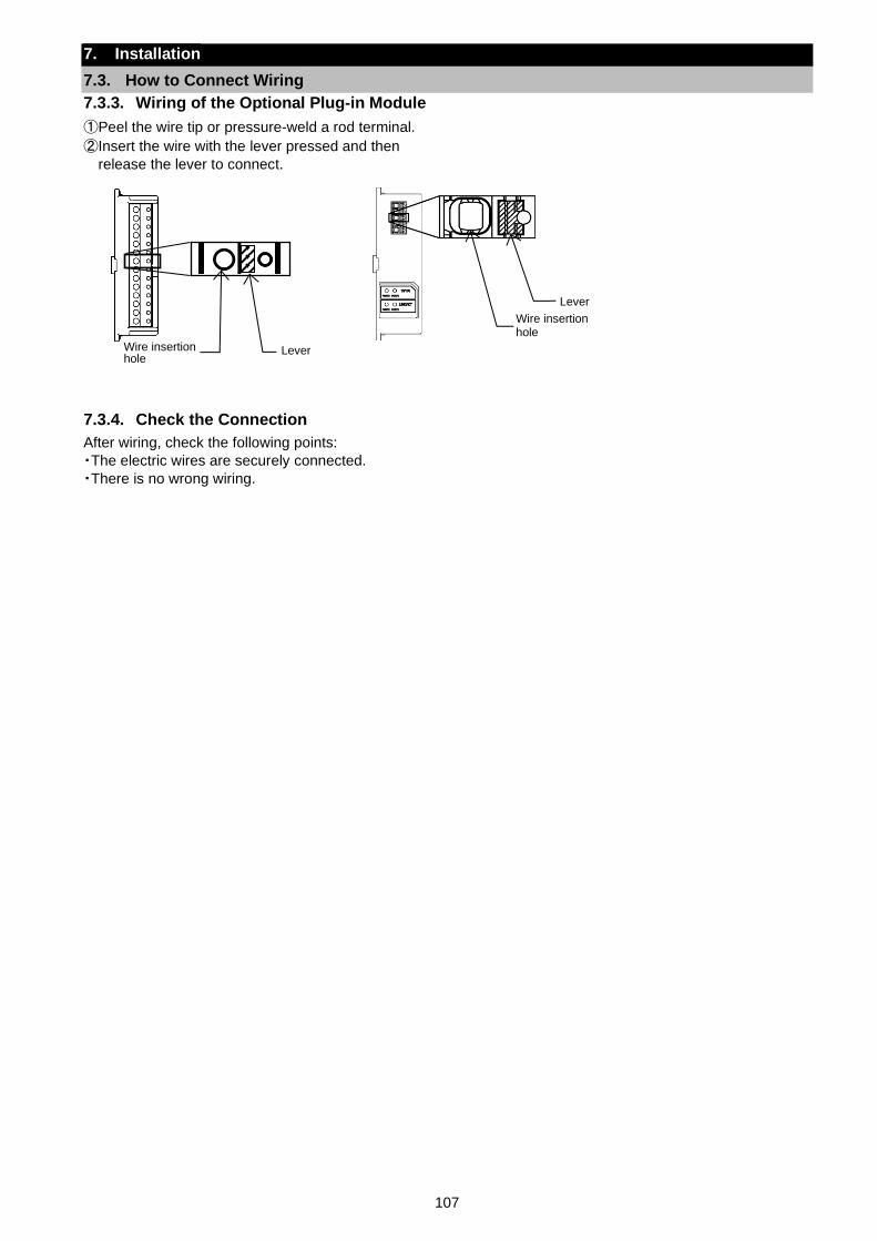
107
7. Installation
7.3. How to Connect Wiring
7.3.3. Wiring of the Optional Plug-in Module
①Peel the wire tip or pressure-weld a rod terminal.
②Insert the wire with the lever pressed and then
release the lever to connect.
7.3.4. Check the Connection
After wiring, check the following points:
・The electric wires are securely connected.
・There is no wrong wiring.
Lever Wire insertion hole
Wire insertion hole
Lever
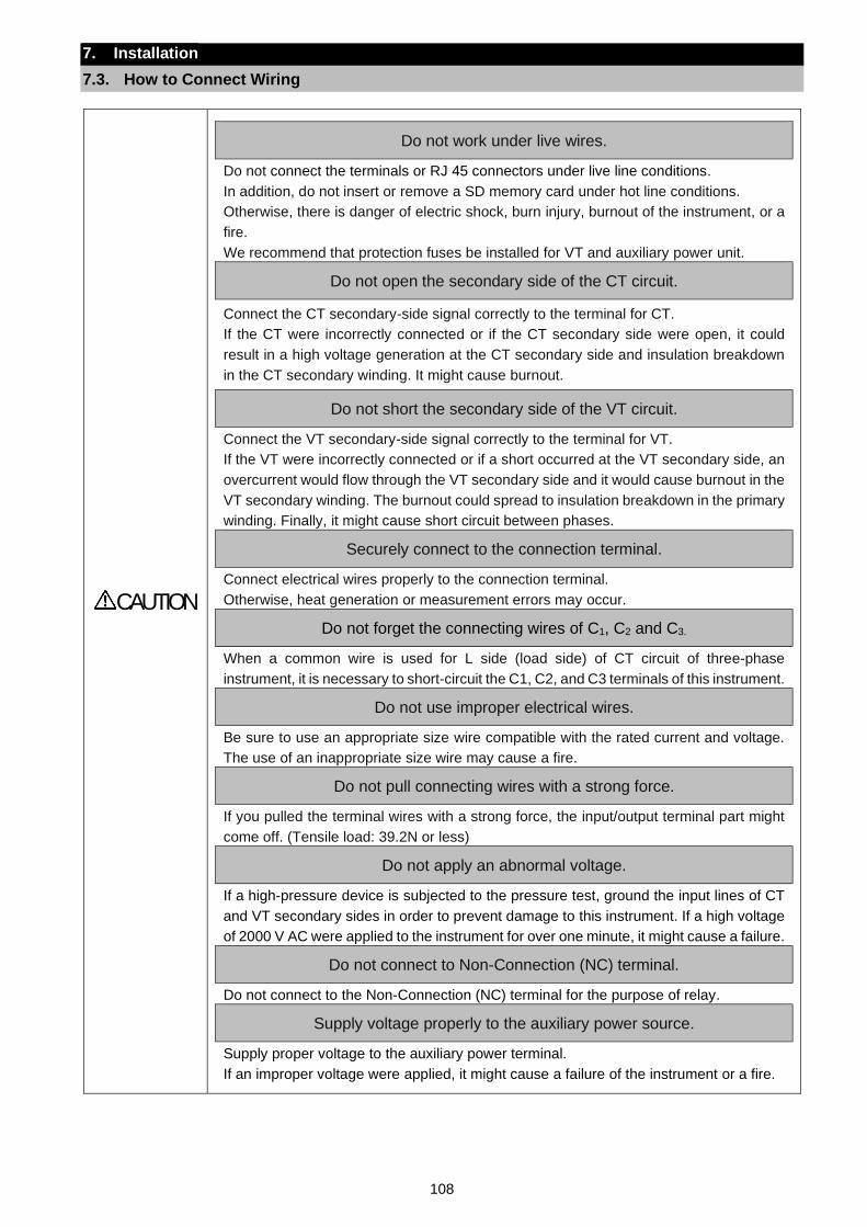
108
7. Installation
7.3. How to Connect Wiring
CAUTION
Do not work under live wires.
Do not connect the terminals or RJ 45 connectors under live line conditions.
In addition, do not insert or remove a SD memory card under hot line conditions.
Otherwise, there is danger of electric shock, burn injury, burnout of the instrument, or a
fire.
We recommend that protection fuses be installed for VT and auxiliary power unit.
Do not open the secondary side of the CT circuit.
Connect the CT secondary-side signal correctly to the terminal for CT.
If the CT were incorrectly connected or if the CT secondary side were open, it could
result in a high voltage generation at the CT secondary side and insulation breakdown
in the CT secondary winding. It might cause burnout.
Do not short the secondary side of the VT circuit.
Connect the VT secondary-side signal correctly to the terminal for VT.
If the VT were incorrectly connected or if a short occurred at the VT secondary side, an
overcurrent would flow through the VT secondary side and it would cause burnout in the
VT secondary winding. The burnout could spread to insulation breakdown in the primary
winding. Finally, it might cause short circuit between phases.
Securely connect to the connection terminal.
Connect electrical wires properly to the connection terminal.
Otherwise, heat generation or measurement errors may occur.
Do not forget the connecting wires of C1, C2 and C3.
When a common wire is used for L side (load side) of CT circuit of three-phase
instrument, it is necessary to short-circuit the C1, C2, and C3 terminals of this instrument.
Do not use improper electrical wires.
Be sure to use an appropriate size wire compatible with the rated current and voltage.
The use of an inappropriate size wire may cause a fire.
Do not pull connecting wires with a strong force.
If you pulled the terminal wires with a strong force, the input/output terminal part might
come off. (Tensile load: 39.2N or less)
Do not apply an abnormal voltage.
If a high-pressure device is subjected to the pressure test, ground the input lines of CT
and VT secondary sides in order to prevent damage to this instrument. If a high voltage
of 2000 V AC were applied to the instrument for over one minute, it might cause a failure.
Do not connect to Non-Connection (NC) terminal.
Do not connect to the Non-Connection (NC) terminal for the purpose of relay.
Supply voltage properly to the auxiliary power source.
Supply proper voltage to the auxiliary power terminal.
If an improper voltage were applied, it might cause a failure of the instrument or a fire.
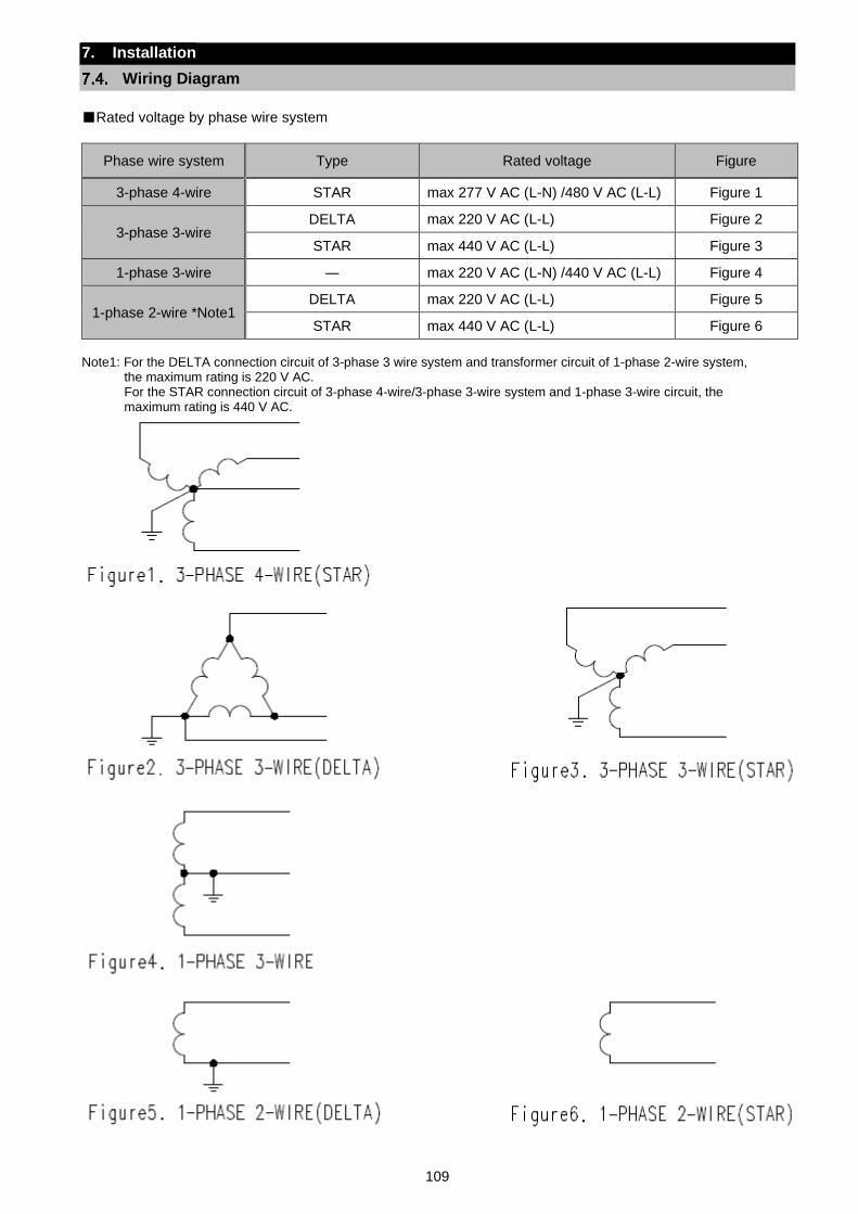
109
7. Installation
Wiring Diagram
Rated voltage by phase wire system
Phase wire system Type Rated voltage Figure
3-phase 4-wire STAR max 277 V AC (L-N) /480 V AC (L-L) Figure 1
3-phase 3-wire DELTA max 220 V AC (L-L) Figure 2
STAR max 440 V AC (L-L) Figure 3
1-phase 3-wire ― max 220 V AC (L-N) /440 V AC (L-L) Figure 4
1-phase 2-wire *Note1 DELTA max 220 V AC (L-L) Figure 5
STAR max 440 V AC (L-L) Figure 6
Note1: For the DELTA connection circuit of 3-phase 3 wire system and transformer circuit of 1-phase 2-wire system,
the maximum rating is 220 V AC. For the STAR connection circuit of 3-phase 4-wire/3-phase 3-wire system and 1-phase 3-wire circuit, the maximum rating is 440 V AC.
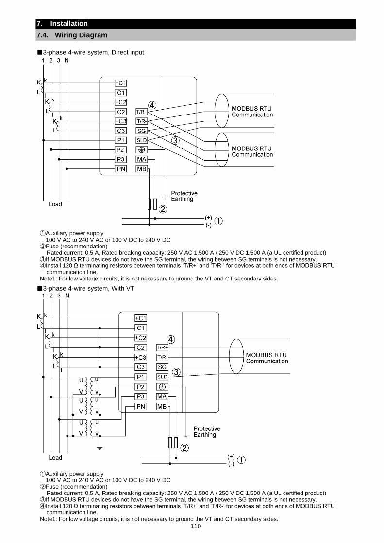
110
7. Installation
7.4. Wiring Diagram
3-phase 4-wire system, Direct input
3-phase 4-wire system, With VT
①Auxiliary power supply 100 V AC to 240 V AC or 100 V DC to 240 V DC
②Fuse (recommendation) Rated current: 0.5 A, Rated breaking capacity: 250 V AC 1,500 A / 250 V DC 1,500 A (a UL certified product)
③If MODBUS RTU devices do not have the SG terminal, the wiring between SG terminals is not necessary. ④Install 120 Ω terminating resistors between terminals ‘T/R+’ and ‘T/R-’ for devices at both ends of MODBUS RTU
communication line. Note1: For low voltage circuits, it is not necessary to ground the VT and CT secondary sides.
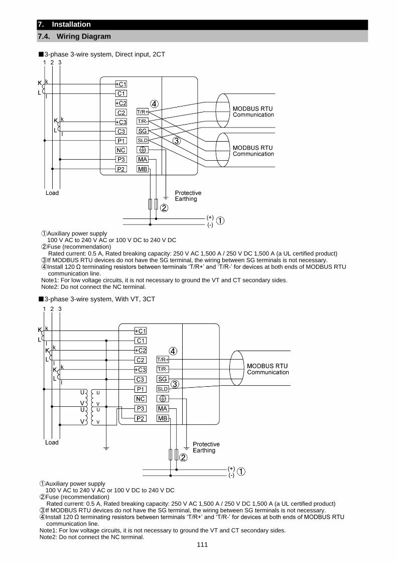
111
7. Installation
7.4. Wiring Diagram
3-phase 3-wire system, Direct input, 2CT
3-phase 3-wire system, With VT, 3CT
①Auxiliary power supply 100 V AC to 240 V AC or 100 V DC to 240 V DC
②Fuse (recommendation) Rated current: 0.5 A, Rated breaking capacity: 250 V AC 1,500 A / 250 V DC 1,500 A (a UL certified product)
③If MODBUS RTU devices do not have the SG terminal, the wiring between SG terminals is not necessary. ④Install 120 Ω terminating resistors between terminals ‘T/R+’ and ‘T/R-’ for devices at both ends of MODBUS RTU
communication line. Note1: For low voltage circuits, it is not necessary to ground the VT and CT secondary sides. Note2: Do not connect the NC terminal.
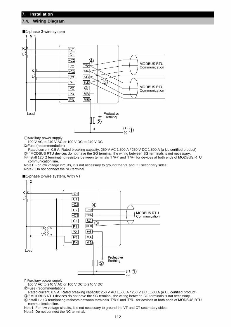
112
7. Installation
7.4. Wiring Diagram
1-phase 3-wire system
1-phase 2-wire system, With VT
①Auxiliary power supply 100 V AC to 240 V AC or 100 V DC to 240 V DC
②Fuse (recommendation) Rated current: 0.5 A, Rated breaking capacity: 250 V AC 1,500 A / 250 V DC 1,500 A (a UL certified product)
③If MODBUS RTU devices do not have the SG terminal, the wiring between SG terminals is not necessary. ④Install 120 Ω terminating resistors between terminals ‘T/R+’ and ‘T/R-’ for devices at both ends of MODBUS RTU
communication line. Note1: For low voltage circuits, it is not necessary to ground the VT and CT secondary sides. Note2: Do not connect the NC terminal.
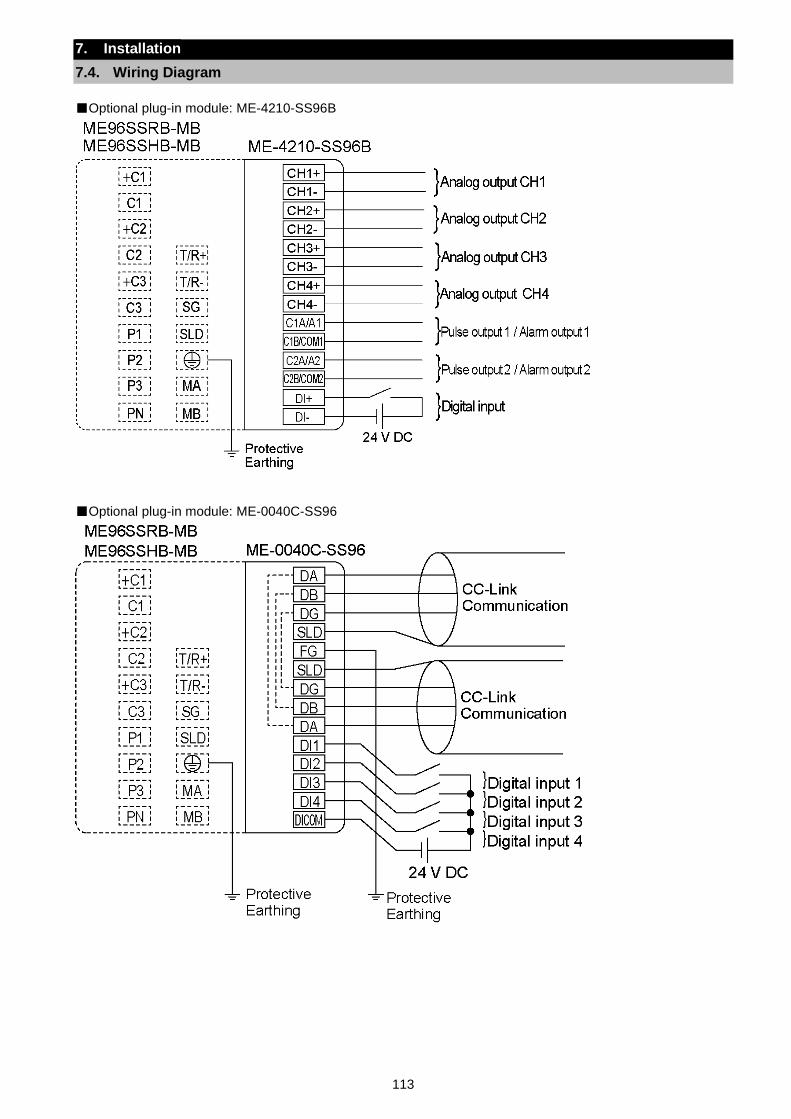
113
7. Installation
7.4. Wiring Diagram
Optional plug-in module: ME-4210-SS96B
Optional plug-in module: ME-0040C-SS96
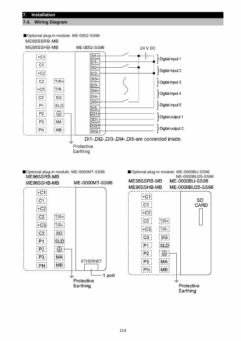
114
7. Installation
7.4. Wiring Diagram
Optional plug-in module: ME-0052-SS96
Optional plug-in module: ME-0000MT-SS96
Optional plug-in module: ME-0000BU-SS96 ME-0000BU25-SS96
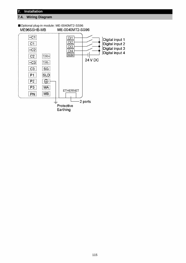
115
7. Installation
7.4. Wiring Diagram
Optional plug-in module: ME-0040MT2-SS96
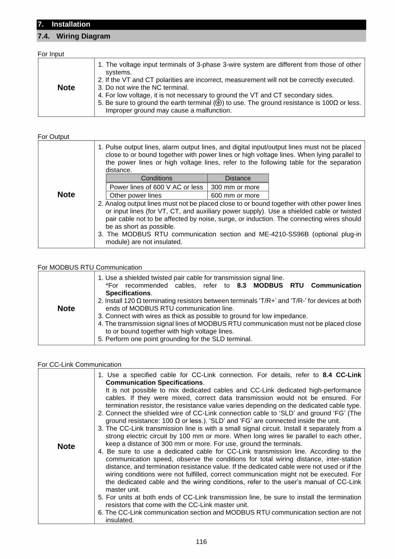
116
7. Installation
7.4. Wiring Diagram
For Input
Note
1. The voltage input terminals of 3-phase 3-wire system are different from those of other systems.
2. If the VT and CT polarities are incorrect, measurement will not be correctly executed. 3. Do not wire the NC terminal. 4. For low voltage, it is not necessary to ground the VT and CT secondary sides. 5. Be sure to ground the earth terminal ( ) to use. The ground resistance is 100Ω or less.
Improper ground may cause a malfunction.
For Output
Note
1. Pulse output lines, alarm output lines, and digital input/output lines must not be placed close to or bound together with power lines or high voltage lines. When lying parallel to the power lines or high voltage lines, refer to the following table for the separation distance.
Conditions Distance
Power lines of 600 V AC or less 300 mm or more
Other power lines 600 mm or more
2. Analog output lines must not be placed close to or bound together with other power lines or input lines (for VT, CT, and auxiliary power supply). Use a shielded cable or twisted pair cable not to be affected by noise, surge, or induction. The connecting wires should be as short as possible.
3. The MODBUS RTU communication section and ME-4210-SS96B (optional plug-in module) are not insulated.
For MODBUS RTU Communication
Note
1. Use a shielded twisted pair cable for transmission signal line. *For recommended cables, refer to 8.3 MODBUS RTU Communication Specifications.
2. Install 120 Ω terminating resistors between terminals ‘T/R+’ and ‘T/R-’ for devices at both ends of MODBUS RTU communication line.
3. Connect with wires as thick as possible to ground for low impedance. 4. The transmission signal lines of MODBUS RTU communication must not be placed close
to or bound together with high voltage lines. 5. Perform one point grounding for the SLD terminal.
For CC-Link Communication
Note
1. Use a specified cable for CC-Link connection. For details, refer to 8.4 CC-Link Communication Specifications. It is not possible to mix dedicated cables and CC-Link dedicated high-performance cables. If they were mixed, correct data transmission would not be ensured. For termination resistor, the resistance value varies depending on the dedicated cable type.
2. Connect the shielded wire of CC-Link connection cable to ‘SLD’ and ground ‘FG’ (The ground resistance: 100 Ω or less.). ‘SLD’ and ‘FG’ are connected inside the unit.
3. The CC-Link transmission line is with a small signal circuit. Install it separately from a strong electric circuit by 100 mm or more. When long wires lie parallel to each other, keep a distance of 300 mm or more. For use, ground the terminals.
4. Be sure to use a dedicated cable for CC-Link transmission line. According to the communication speed, observe the conditions for total wiring distance, inter-station distance, and termination resistance value. If the dedicated cable were not used or if the wiring conditions were not fulfilled, correct communication might not be executed. For the dedicated cable and the wiring conditions, refer to the user’s manual of CC-Link master unit.
5. For units at both ends of CC-Link transmission line, be sure to install the termination resistors that come with the CC-Link master unit.
6. The CC-Link communication section and MODBUS RTU communication section are not insulated.

117
7. Installation
7.4. Wiring Diagram
For MODBUS TCP Communication
Note
1. For 100 Mbps communication with 100 BASE-TX connection, a communication error may occur depending on the installation environment due to the effect of high frequency noise from devices other than this instrument. To prevent the effect of high frequency noise, take the following measures against it when configuring a network system.
(1) Wiring connection
・Twisted pair cables must not be placed close to or bound together with the main circuit or power lines.
・Put the twisted pair cable in a duct. (2) Communication method
・Increase the communication retry count as necessary.
・Replace with a 10 Mbps hub for connection use and communicate with a data transmission speed of 10 Mbps.
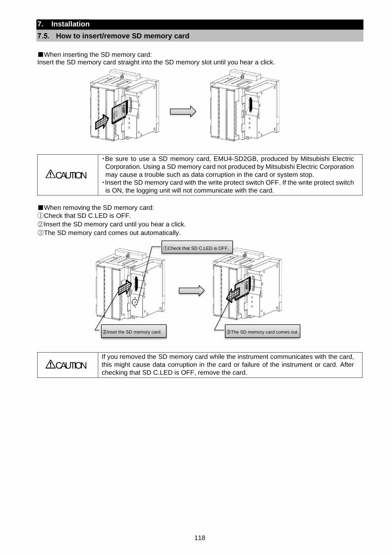
118
7. Installation
How to insert/remove SD memory card
When inserting the SD memory card: Insert the SD memory card straight into the SD memory slot until you hear a click.
CAUTION
・Be sure to use a SD memory card, EMU4-SD2GB, produced by Mitsubishi Electric
Corporation. Using a SD memory card not produced by Mitsubishi Electric Corporation
may cause a trouble such as data corruption in the card or system stop.
・Insert the SD memory card with the write protect switch OFF. If the write protect switch
is ON, the logging unit will not communicate with the card.
When removing the SD memory card:
①Check that SD C.LED is OFF.
②Insert the SD memory card until you hear a click.
③The SD memory card comes out automatically.
CAUTION
If you removed the SD memory card while the instrument communicates with the card,
this might cause data corruption in the card or failure of the instrument or card. After
checking that SD C.LED is OFF, remove the card.
①Check that SD C.LED is OFF.
②Inset the SD memory card. ③The SD memory card comes out.
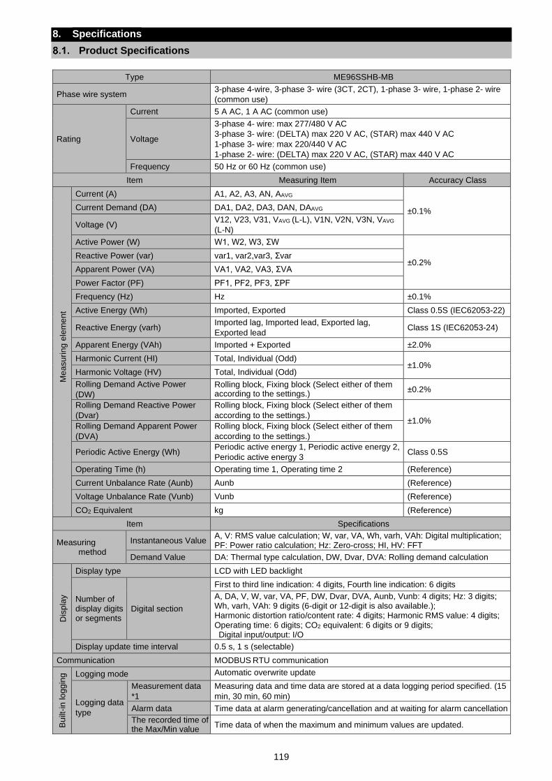
119
8. Specifications
Product Specifications
Type ME96SSHB-MB
Phase wire system 3-phase 4-wire, 3-phase 3- wire (3CT, 2CT), 1-phase 3- wire, 1-phase 2- wire
(common use)
Rating
Current 5 A AC, 1 A AC (common use)
Voltage
3-phase 4- wire: max 277/480 V AC
3-phase 3- wire: (DELTA) max 220 V AC, (STAR) max 440 V AC
1-phase 3- wire: max 220/440 V AC
1-phase 2- wire: (DELTA) max 220 V AC, (STAR) max 440 V AC
Frequency 50 Hz or 60 Hz (common use)
Item Measuring Item Accuracy Class
Me
asu
rin
g e
lem
en
t
Current (A) A1, A2, A3, AN, AAVG
±0.1% Current Demand (DA) DA1, DA2, DA3, DAN, DAAVG
Voltage (V) V12, V23, V31, VAVG (L-L), V1N, V2N, V3N, VAVG
(L-N)
Active Power (W) W1, W2, W3, ΣW
±0.2% Reactive Power (var) var1, var2,var3, Σvar
Apparent Power (VA) VA1, VA2, VA3, ΣVA
Power Factor (PF) PF1, PF2, PF3, ΣPF
Frequency (Hz) Hz ±0.1%
Active Energy (Wh) Imported, Exported Class 0.5S (IEC62053-22)
Reactive Energy (varh) Imported lag, Imported lead, Exported lag,
Exported lead Class 1S (IEC62053-24)
Apparent Energy (VAh) Imported + Exported ±2.0%
Harmonic Current (HI) Total, Individual (Odd) ±1.0%
Harmonic Voltage (HV) Total, Individual (Odd)
Rolling Demand Active Power
(DW)
Rolling block, Fixing block (Select either of them according to the settings.)
±0.2%
Rolling Demand Reactive Power
(Dvar)
Rolling block, Fixing block (Select either of them
according to the settings.) ±1.0%
Rolling Demand Apparent Power
(DVA)
Rolling block, Fixing block (Select either of them
according to the settings.)
Periodic Active Energy (Wh) Periodic active energy 1, Periodic active energy 2,
Periodic active energy 3 Class 0.5S
Operating Time (h) Operating time 1, Operating time 2 (Reference)
Current Unbalance Rate (Aunb) Aunb (Reference)
Voltage Unbalance Rate (Vunb) Vunb (Reference)
CO2 Equivalent kg (Reference)
Item Specifications
Measuring method
Instantaneous Value A, V: RMS value calculation; W, var, VA, Wh, varh, VAh: Digital multiplication; PF: Power ratio calculation; Hz: Zero-cross; HI, HV: FFT
Demand Value DA: Thermal type calculation, DW, Dvar, DVA: Rolling demand calculation
Dis
pla
y
Display type LCD with LED backlight
Number of display digits or segments
Digital section
First to third line indication: 4 digits, Fourth line indication: 6 digits
A, DA, V, W, var, VA, PF, DW, Dvar, DVA, Aunb, Vunb: 4 digits; Hz: 3 digits; Wh, varh, VAh: 9 digits (6-digit or 12-digit is also available.); Harmonic distortion ratio/content rate: 4 digits; Harmonic RMS value: 4 digits; Operating time: 6 digits; CO2 equivalent: 6 digits or 9 digits; Digital input/output: I/O
Display update time interval 0.5 s, 1 s (selectable)
Communication MODBUS RTU communication
Bu
ilt-in
lo
gg
ing Logging mode Automatic overwrite update
Logging data
type
Measurement data
*1
Measuring data and time data are stored at a data logging period specified. (15
min, 30 min, 60 min)
Alarm data Time data at alarm generating/cancellation and at waiting for alarm cancellation
The recorded time of the Max/Min value
Time data of when the maximum and minimum values are updated.
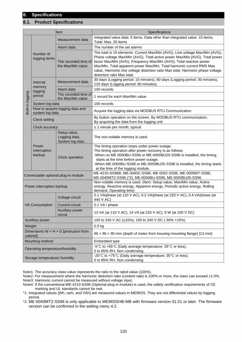
120
8. Specifications
8.1. Product Specifications
Item Specifications
Bu
ilt-in
lo
gg
ing
Number of
logging items
Measurement data Integrated value data: 5 items, Data other than integrated value: 15 items,
Total: Max. 20 items
Alarm data The number of the set alarms
The recorded time of
the Max/Min value
The total is 19 elements: Current Max/Min (AVG), Line voltage Max/Min (AVG),
Phase voltage Max/Min (AVG), Total active power Max/Min (AVG), Total power
factor Max/Min (AVG), Frequency Max/Min (AVG), Total reactive power
Max/Min, Total apparent power Max/Min, Total harmonic current RMS Max
value, Harmonic line voltage distortion ratio Max total, Harmonic phase voltage
distortion ratio Max total
Internal
memory
logging
period
Measurement data 30 days (Logging period: 15 minutes), 60 days (Logging period: 30 minutes),
120 days (Logging period: 60 minutes),
Alarm data 100 records
The recorded time of the Max/Min value
1 record for each Max/Min value
System log data 100 records
How to acquire logging data and system log data
Acquire the logging data via MODBUS RTU Communication
Clock setting By button operation on the screen, By MODBUS RTU communication,
By acquiring the data from the logging unit
Clock accuracy ± 1 minute per month, typical
Power
interruption
backup
Setup value,
Logging data,
System log data
The non-volatile memory is used.
Clock operation
The timing operation stops under power outage.
The timing operation after power recovery is as follows:
∙When no ME-0000BU-SS96 or ME-0000BU25-SS96 is installed, the timing
starts at the time before power outage.
∙When ME-0000BU-SS96 or ME-0000BU25-SS96 is installed, the timing starts
at the time of the logging module.
Connectable optional plug-in module ME-4210-SS96B, ME-0040C-SS96, ME-0052-SS96, ME-0000MT-SS96,
ME-0040MT2-SS96 (*2), ME-0000BU-SS96, ME-0000BU25-SS96
Power interruption backup Non-volatile memory is used. (Item: Setup value, Max/Min value, Active energy, Reactive energy, Apparent energy, Periodic active energy, Rolling demand, Operating time)
VA Consumption
Voltage circuit 0.1 VA/phase (at 110 V AC), 0.2 VA/phase (at 220 V AC), 0.4 VA/phase (at
440 V AC)
Current circuit 0.1 VA / phase
Auxiliary power
circuit 13 VA (at 110 V AC), 14 VA (at 220 V AC), 9 W (at 100 V DC)
Auxiliary power 100 to 240 V AC (±15%), 100 to 240 V DC (-30% +15%)
Weight 0.5 kg
Dimensions W × H × D [protrusion from
cabinet] 96 × 96 × 90 mm (depth of meter from housing mounting flange) [13 mm]
Mounting method Embedded type
Operating temperature/humidity -5°C to +55°C (Daily average temperature: 35°C or less),
0 to 85% RH, Non condensing
Storage temperature/ humidity -25°C to +75°C (Daily average temperature: 35°C or less),
0 to 85% RH, Non condensing
Note1: The accuracy class value represents the ratio to the rated value (100%). Note2: For measurement where the harmonic distortion ratio (content rate) is 100% or more, the class can exceed ±1.0%. Note3: Harmonic current cannot be measured without voltage input. Note4: If the conventional ME-4210-SS96 (Optional plug-in module) is used, the safety certification requirements of CE
marking and UL standards cannot be met. *1. Integrated values (Wh, varh, and VAh) are measured values in ME96SS. They are not differential values by logging
period.
*2. ME-0040MT2-SS96 is only applicable to ME96SSHB-MB with firmware version 01.01 or later. The firmware version can be confirmed in the setting menu 4.2.
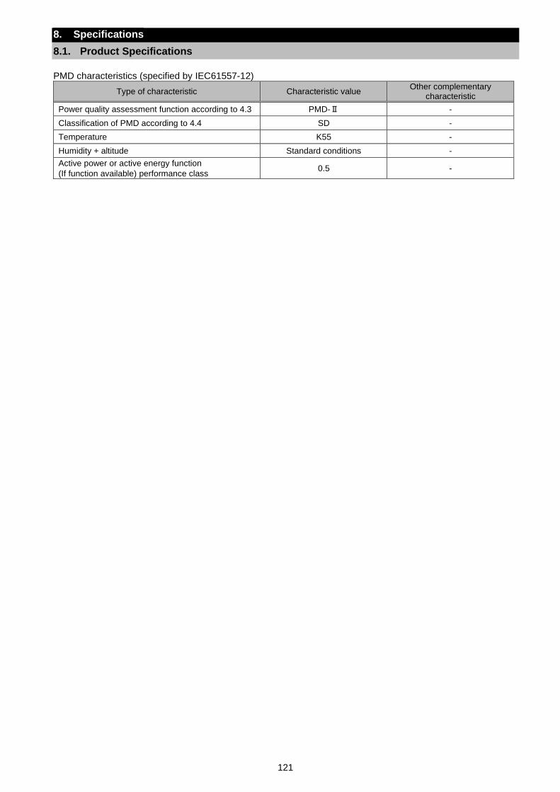
121
8. Specifications
8.1. Product Specifications
PMD characteristics (specified by IEC61557-12)
Type of characteristic Characteristic value Other complementary
characteristic
Power quality assessment function according to 4.3 PMD-Ⅱ -
Classification of PMD according to 4.4 SD -
Temperature K55 -
Humidity + altitude Standard conditions -
Active power or active energy function
(If function available) performance class 0.5 -
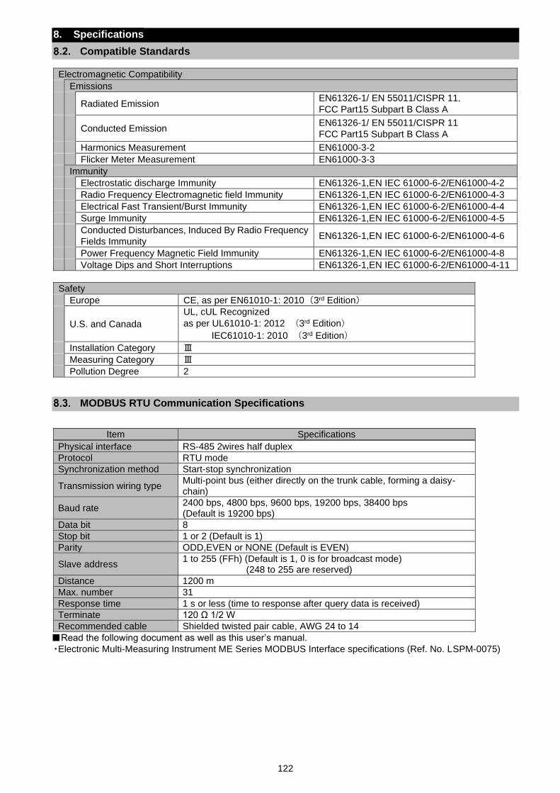
122
8. Specifications
Compatible Standards
Electromagnetic Compatibility
Emissions
Radiated Emission EN61326-1/ EN 55011/CISPR 11,
FCC Part15 Subpart B Class A
Conducted Emission EN61326-1/ EN 55011/CISPR 11
FCC Part15 Subpart B Class A
Harmonics Measurement EN61000-3-2
Flicker Meter Measurement EN61000-3-3
Immunity
Electrostatic discharge Immunity EN61326-1,EN IEC 61000-6-2/EN61000-4-2
Radio Frequency Electromagnetic field Immunity EN61326-1,EN IEC 61000-6-2/EN61000-4-3
Electrical Fast Transient/Burst Immunity EN61326-1,EN IEC 61000-6-2/EN61000-4-4
Surge Immunity EN61326-1,EN IEC 61000-6-2/EN61000-4-5
Conducted Disturbances, Induced By Radio Frequency
Fields Immunity EN61326-1,EN IEC 61000-6-2/EN61000-4-6
Power Frequency Magnetic Field Immunity EN61326-1,EN IEC 61000-6-2/EN61000-4-8
Voltage Dips and Short Interruptions EN61326-1,EN IEC 61000-6-2/EN61000-4-11
Safety
Europe CE, as per EN61010-1: 2010 (3rd Edition)
U.S. and Canada
UL, cUL Recognized
as per UL61010-1: 2012 (3rd Edition)
IEC61010-1: 2010 (3rd Edition)
Installation Category Ⅲ
Measuring Category Ⅲ
Pollution Degree 2
MODBUS RTU Communication Specifications
Item Specifications
Physical interface RS-485 2wires half duplex
Protocol RTU mode
Synchronization method Start-stop synchronization
Transmission wiring type Multi-point bus (either directly on the trunk cable, forming a daisy-chain)
Baud rate 2400 bps, 4800 bps, 9600 bps, 19200 bps, 38400 bps (Default is 19200 bps)
Data bit 8
Stop bit 1 or 2 (Default is 1)
Parity ODD,EVEN or NONE (Default is EVEN)
Slave address 1 to 255 (FFh) (Default is 1, 0 is for broadcast mode)
(248 to 255 are reserved)
Distance 1200 m
Max. number 31
Response time 1 s or less (time to response after query data is received)
Terminate 120 Ω 1/2 W
Recommended cable Shielded twisted pair cable, AWG 24 to 14
Read the following document as well as this user’s manual.
・Electronic Multi-Measuring Instrument ME Series MODBUS Interface specifications (Ref. No. LSPM-0075)
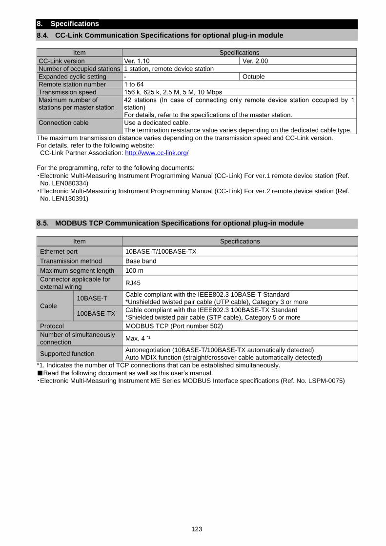
123
8. Specifications
CC-Link Communication Specifications for optional plug-in module
Item Specifications
CC-Link version Ver. 1.10 Ver. 2.00
Number of occupied stations 1 station, remote device station
Expanded cyclic setting - Octuple
Remote station number 1 to 64
Transmission speed 156 k, 625 k, 2.5 M, 5 M, 10 Mbps
Maximum number of stations per master station
42 stations (In case of connecting only remote device station occupied by 1 station) For details, refer to the specifications of the master station.
Connection cable Use a dedicated cable. The termination resistance value varies depending on the dedicated cable type.
The maximum transmission distance varies depending on the transmission speed and CC-Link version. For details, refer to the following website: CC-Link Partner Association: http://www.cc-link.org/
For the programming, refer to the following documents:
・Electronic Multi-Measuring Instrument Programming Manual (CC-Link) For ver.1 remote device station (Ref. No. LEN080334)
・Electronic Multi-Measuring Instrument Programming Manual (CC-Link) For ver.2 remote device station (Ref. No. LEN130391)
MODBUS TCP Communication Specifications for optional plug-in module
Item Specifications
Ethernet port 10BASE-T/100BASE-TX
Transmission method Base band
Maximum segment length 100 m
Connector applicable for external wiring
RJ45
Cable
10BASE-T Cable compliant with the IEEE802.3 10BASE-T Standard *Unshielded twisted pair cable (UTP cable), Category 3 or more
100BASE-TX Cable compliant with the IEEE802.3 100BASE-TX Standard *Shielded twisted pair cable (STP cable), Category 5 or more
Protocol MODBUS TCP (Port number 502)
Number of simultaneously connection
Max. 4 *1
Supported function Autonegotiation (10BASE-T/100BASE-TX automatically detected) Auto MDIX function (straight/crossover cable automatically detected)
*1. Indicates the number of TCP connections that can be established simultaneously.
Read the following document as well as this user’s manual. ・Electronic Multi-Measuring Instrument ME Series MODBUS Interface specifications (Ref. No. LSPM-0075)
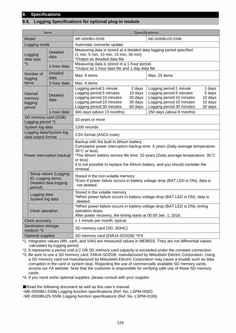
124
8. Specifications
Logging Specifications for optional plug-in module
Item Specifications
Model ME-0000BU-SS96 ME-0000BU25-SS96
Logging mode Automatic overwrite update
Logging data type *1
Detailed data
Measuring data is stored at a detailed data logging period specified. (1 min, 5 min, 10 min, 15 min, 30 min) *Output as detailed data file
1-hour data Measuring data is stored in a 1-hour period. *Output as 1-hour data file and 1-day data file
Number of logging items
Detailed data
Max. 6 items Max. 25 items
1-hour data Max. 6 items
Internal memory logging period
Detailed data
Logging period:1 minute Logging period:5 minutes Logging period:10 minutes Logging period:15 minutes Logging period:30 minutes
2 days 10 days 20 days 30 days 60 days
Logging period:1 minute Logging period:5 minutes Logging period:10 minutes Logging period:15 minutes Logging period:30 minutes
1 days 5 days
10 days 15 days 30 days
1-hour data 400 days (about 13 months) 250 days (about 8 months)
SD memory card (2GB) Logging period *2
10 years or more
System log data 1200 records
Logging data/System log data output format
CSV format (ASCII code)
Power interruption backup
Backup with the built-in lithium battery Cumulative power interruption backup time: 5 years (Daily average temperature: 35°C or less) *The lithium battery service life time: 10 years (Daily average temperature: 35°C or less) It is not possible to replace the lithium battery, and you should consider the renewal.
Setup values (Logging ID, Logging items, Detailed data logging period)
Stored in the non-volatile memory *Even if power failure occurs in battery voltage drop (BAT.LED is ON), data is not deleted.
Logging data System log data
Stored in the volatile memory *When power failure occurs in battery voltage drop (BAT.LED is ON), data is deleted.
Clock operation *When power failure occurs in battery voltage drop (BAT.LED is ON), timing operation stops. After power recovery, the timing starts at 00:00 Jan. 1, 2016.
Clock accuracy ± 1 minute per month, typical
Destination storage medium *3
SD memory card (SD, SDHC)
Optional supplies SD memory card (EMU4-SD2GB) *3*4
*1. Integrated values (Wh, varh, and VAh) are measured values in ME96SS. They are not differential values calculated by logging period.
*2. It represents a period until a 2 GB SD memory card capacity is exceeded under the constant connection. *3. Be sure to use a SD memory card, EMU4-SD2GB, manufactured by Mitsubishi Electric Corporation. Using
a SD memory card not manufactured by Mitsubishi Electric Corporation may cause a trouble such as data corruption in the card or system stop. Regarding the use of commercially available SD memory cards, access our FA website. Note that the customer is responsible for verifying safe use of those SD memory cards.
*4. If you need some optional supplies, please consult with your supplier.
Read the following document as well as this user’s manual. ・ME-0000BU-SS96 Logging function specifications (Ref. No. LSPM-0092)
・ME-0000BU25-SS96 Logging function specifications (Ref. No. LSPM-0106)

125
8. Specifications
Input / output specifications (optional plug-in module)
Item Specifications
Analog output
Output specifications 4 mA to 20 mA
Load resistance 600 Ω or less
Response time 1 second or less (Hz: 2 seconds or less, HI, HV: 5 seconds or less)
Pulse/Alarm
output
Switch type No-voltage a-contact
Contact capacity 35 V DC, 0.1 A or less
Pulse width 0.125 s, 0.5 s, 1.0 s
Digital input
(DI)
Contact capacity 24 V DC (19 V DC to 30 V DC), 7 mA or less
Signal width 30 ms or more
Digital output
(DO)
Switch type No-voltage a-contact
Contact capacity 35 V DC, 0.2 A or less

126
8. Specifications
Setting Table (Factory Default Settings and Customer’s Notes Settings)
Setting menu No. Setting item Factory default setting Customer’s notes
1
1.1 Phase wire system 3P4 (3-phase 4-wire)
1.2 Display pattern P01
1.2.1 Pattern P00 ―
1.3 VT/Direct voltage no (Without VT)
1.3.1 Direct voltage 220/380 V
1.3.2 VT secondary voltage ―
1.3.3 VT primary voltage ―
1.4 CT secondary current 5 A
1.4.1 CT primary current 5 A
1.5 Frequency 50 Hz
1.6 Rolling demand time period
(Interval time period) 15 min
1.6.1 Subinterval time period 1 min
1.7 Current demand time period 0 s
2
2.1
Communication method selection
*When ME-0040C-SS96, ME-0000MT-
SS96 or ME-0040MT2-SS96 is installed
CC or tcP
(By option)
2.2 MODBUS RTU address 1
2.2.1 MODBUS RTU baud rate 19.2 kbps
2.2.2 MODBUS RTU parity EVEn (even)
2.2.3 MODBUS RTU stop bit 1
2.3 CC-Link station number 1
2.3.1 CC-Link baud rate 156 kbps
2.3.2 CC-Link version setting 1.10
2.3.3 Communication reset oFF (Without reset)
2.4 MODBUS TCP IP address 192.168.3.10
MODBUS TCP subnet mask 255.255.255.0
MODBUS TCP default gateway use oFF (Not use)
MODBUS TCP default gateway address 127.0.0.1
Communication reset oFF (Without reset)
3
3.1 Active/Reactive Energy measurement Combination Ⅰ
3.2 Harmonics display on (Display)
3.3 Unbalance rate on (Display)
4
4.1 Model display (By model)
4.2 Version display (By version)
4.3 Backlight brightness 3
4.4 Backlight Auto off/ON Auto (Auto off)
4.5 Display update time 0.5 s
5
5.1 Upper/Lower limit alarm item 1 non
5.1.1 Upper/Lower limit alarm value 1 ―
5.2 Upper/Lower limit alarm item 2 non
5.2.1 Upper/Lower limit alarm value 2 ―
5.3 Upper/Lower limit alarm item 3 non
5.3.1 Upper/Lower limit alarm value 3 ―
5.4 Upper/Lower limit alarm item 4 non
5.4.1 Upper/Lower limit alarm value 4 ―
5.5 Alarm delay time ―
5.6 Alarm reset method ―
5.7 Backlight blinking for alarm ―
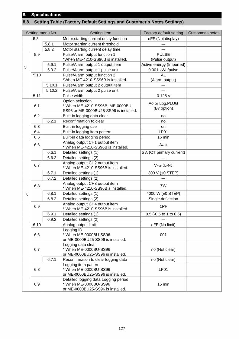
127
8. Specifications
8.8. Setting Table (Factory Default Settings and Customer’s Notes Settings)
Setting menu No. Setting item Factory default setting Customer’s notes
5
5.8 Motor starting current delay function oFF (Not display)
5.8.1 Motor starting current threshold ―
5.8.2 Motor starting current delay time ―
5.9
Pulse/Alarm output function 1
*When ME-4210-SS96B is installed.
PULSE
(Pulse output)
5.9.1 Pulse/Alarm output 1 output item Active energy (Imported)
5.9.2 Pulse/Alarm output 1 pulse unit 0.001 kWh/pulse
5.10
Pulse/Alarm output function 2
*When ME-4210-SS96B is installed.
AL
(Alarm output)
5.10.1 Pulse/Alarm output 2 output item ―
5.10.2 Pulse/Alarm output 2 pulse unit ―
5.11 Pulse width 0.125 s
6
6.1
Option selection
* When ME-4210-SS96B, ME-0000BU-
SS96 or ME-0000BU25-SS96 is installed.
Ao or Log.PLUG
(By option)
6.2 Built-in logging data clear no
6.2.1 Reconfirmation to clear no
6.3 Built-in logging use on
6.4 Built-in logging item pattern LP01
6.5 Built-in data logging period 15 min
6.6 Analog output CH1 output item
* When ME-4210-SS96B is installed. AAVG
6.6.1 Detailed settings (1) 5 A (CT primary current)
6.6.2 Detailed settings (2) ―
6.7 Analog output CH2 output item
* When ME-4210-SS96B is installed. VAVG(L-N)
6.7.1 Detailed settings (1) 300 V (±0 STEP)
6.7.2 Detailed settings (2) ―
6.8 Analog output CH3 output item
* When ME-4210-SS96B s installed. ΣW
6.8.1 Detailed settings (1) 4000 W (±0 STEP)
6.8.2 Detailed settings (2) Single deflection
6.9 Analog output CH4 output item
* When ME-4210-SS96B is installed. ΣPF
6.9.1 Detailed settings (1) 0.5 (-0.5 to 1 to 0.5)
6.9.2 Detailed settings (2) ―
6.10 Analog output limit oFF (No limit)
6.6
Logging ID
* When ME-0000BU-SS96
or ME-0000BU25-SS96 is installed.
001
6.7
Logging data clear
* When ME-0000BU-SS96
or ME-0000BU25-SS96 is installed.
no (Not clear)
6.7.1 Reconfirmation to clear logging data no (Not clear)
6.8
Logging item pattern
* When ME-0000BU-SS96
or ME-0000BU25-SS96 is installed.
LP01
6.9
Detailed logging data Logging period
* When ME-0000BU-SS96
or ME-0000BU25-SS96 is installed.
15 min
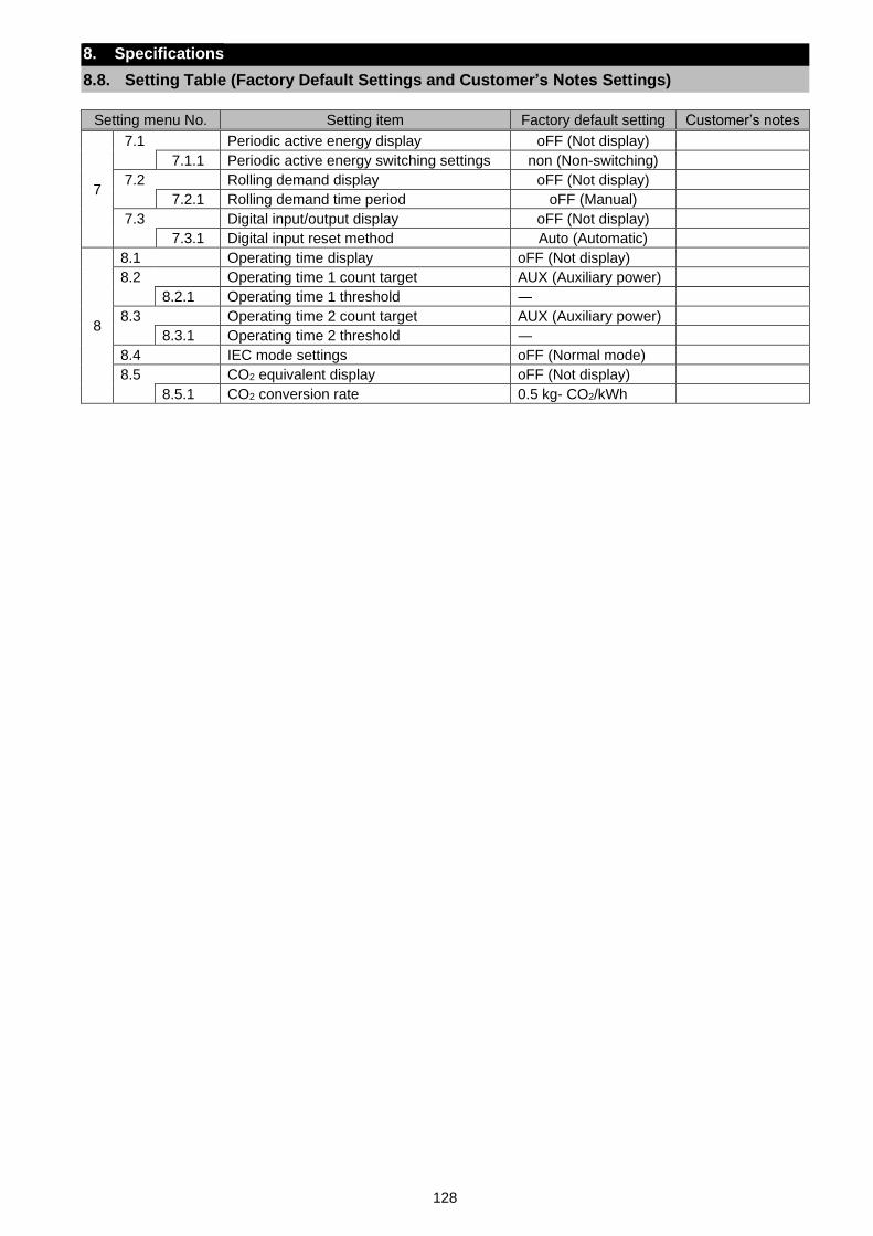
128
8. Specifications
8.8. Setting Table (Factory Default Settings and Customer’s Notes Settings)
Setting menu No. Setting item Factory default setting Customer’s notes
7
7.1 Periodic active energy display oFF (Not display)
7.1.1 Periodic active energy switching settings non (Non-switching)
7.2 Rolling demand display oFF (Not display)
7.2.1 Rolling demand time period oFF (Manual)
7.3 Digital input/output display oFF (Not display)
7.3.1 Digital input reset method Auto (Automatic)
8
8.1 Operating time display oFF (Not display)
8.2 Operating time 1 count target AUX (Auxiliary power)
8.2.1 Operating time 1 threshold ―
8.3 Operating time 2 count target AUX (Auxiliary power)
8.3.1 Operating time 2 threshold ―
8.4 IEC mode settings oFF (Normal mode)
8.5 CO2 equivalent display oFF (Not display)
8.5.1 CO2 conversion rate 0.5 kg- CO2/kWh
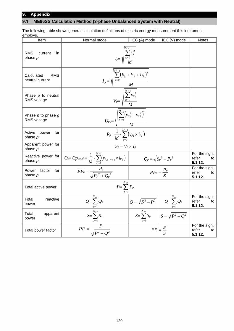
129
9. Appendix
ME96SS Calculation Method (3-phase Unbalanced System with Neutral)
The following table shows general calculation definitions of electric energy measurement this instrument employs.
Item Normal mode IEC (A) mode IEC (V) mode Notes
RMS current in phase p
M
i
I
M
k
kp
p
−
==
1
0
2
Calculated RMS neutral current
( )
M
iii
I
M
k
kkk
N
−
=
++
=
1
0
2321
Phase p to neutral RMS voltage
M
v
V
M
k
kp
p
−
==
1
0
2
Phase p to phase g RMS voltage
( )
M
vv
U
M
k
kgkp
pg
−
=
−
=
1
0
222
Active power for phase p
( )−
=
=1
0
1 M
k
kpkpp ivM
P
Apparent power for phase p
ppp IVS =
Reactive power for phase p
( )−
=
− ==1
0
4/
1 M
k
kpNkpquadp ivM
QpQ 22ppp PSQ −=
For the sign, refer to 5.1.12.
Power factor for phase p 22
pp
pp
QP
PPF
+=
p
pp
S
PPF =
For the sign, refer to 5.1.12.
Total active power =
=phN
p
pPP1
Total reactive power
=
=phN
p
pQQ1
22 PSQ −= =
=phN
p
pQQ1
For the sign, refer to 5.1.12.
Total apparent power
=
=phN
p
pSS1
=
=phN
p
pSS1
22 QPS +=
Total power factor 22 QP
PPF
+=
S
PPF =
For the sign, refer to 5.1.12.
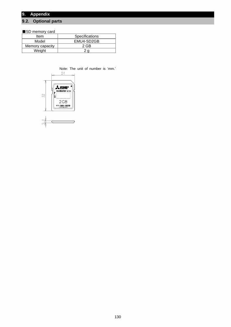
130
9. Appendix
Optional parts
SD memory card
Item Specifications
Model EMU4-SD2GB
Memory capacity 2 GB
Weight 2 g
Note: The unit of number is ‘mm.’
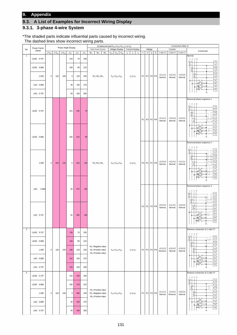
131
9. Appendix
A List of Examples for Incorrect Wiring Display
9.3.1. 3-phase 4-wire System
*The shaded parts indicate influential parts caused by incorrect wiring.
The dashed lines show incorrect wiring parts.
∠V1N ∠V2N ∠V3N ∠I1 ∠I2 ∠I3 W1 W2 W3 V1N V2N V3N I1 I2 I3 1 2 3 N 1 side CT 2 side CT 3 side CT
LEAD 0.707 315 75 195
Normal
LEAD 0.866 330 90 210
1.000 0 120 240
LAG 0.866 30 150 270
LAG 0.707 45 165 285
Reversed phase sequence 1
Reversed phase sequence 2
Reversed phase sequence 3
2
LEAD 0.707 135 75 195
Reverse connection of 1 side CT
LEAD 0.866 150 90 210
1.000 180 120 240
LAG 0.866 210 150 270
LAG 0.707 225 165 285
3
LEAD 0.707 315 255 195
Reverse connection of 2 side CT
LEAD 0.866 330 270 210
1.000 0 300 240
LAG 0.866 30 330 270
LAG 0.707 45 345 285
0 120 240
W1=Negative value
W2=Positive value
W3=Positive value
V1N=V2N=V3N I1=I2=I3 P1
0 120 240
W1=Positive value
W2=Negative value
W3=Positive value
V1N=V2N=V3N I1=I2=I3+C3-C3
NormalP1 P2 P3 PN
+C1-C1
Normal
+C2-C2
Reverse
P2 P3 PN+C1-C1
Reverse
+C2-C2
Normal
+C3-C3
Normal
CurrentConnection
LEAD
I1=I2=I3
P1 P3 P2 PN+C1-C1
Normal
+C3-C3
Normal
+C2-C2
Normal
+C3-C3
Normal
+C2-C2
Normal
0 120 240 W1=W2=W3 V1N=V2N=V3N I1=I2=I3 P1 P2 P3 PN+C1-C1
Normal
+C2-C2
Normal
+C3-C3
Normal
PN
V1N=V2N=V3N
P2 P1 P3
LAG 0.866 30 270 150
No.Power Factor
(Input)
Phase Angle DisplayAt balanced load (V1N=V2N=V3N, I1=I2=I3) Connection (Note 1)
Active Power Display Voltage Display Current Display Voltage
+C1-C1
Normal
+C2-C2
Normal
+C1-C1
Normal
+C3-C3
Normal
0.707
0 240 120
315 195 75
W1=W2=W3
0.707 45 285 165
120
1
LEAD 0.866 330 210 90
P3 P2 P1 PN1.000 0 240
LAG
+C2
C2
+C3
C3
P1
P3
P2
+C1
C1
PN
1 2 3 N
K
L
k
l
K
L
k
l
K
L
k
l
U u
V vU
V vu
v
uU
V
+C2
C2
+C3
C3
P1
P3
P2
+C1
C1
PN
1 2 3 N
K
L
k
l
K
L
k
l
K
L
k
l
U u
V vU
V vu
v
uU
V
+C2
C2
+C3
C3
P1
P3
P2
+C1
C1
PN
1 2 3 N
K
L
k
l
K
L
k
l
K
L
k
l
U u
V vU
V vu
v
uU
V
+C2
C2
+C3
C3
P1
P3
P2
+C1
C1
PN
1 2 3 N
K
L
k
l
K
L
k
l
K
L
k
l
U u
V vU
V vu
v
uU
V
+C2
C2
+C3
C3
P1
P3
P2
+C1
C1
PN
1 2 3 N
K
L
k
l
K
L
k
l
K
L
k
l
U u
V vU
V vu
v
uU
V
+C2
C2
+C3
C3
P1
P3
P2
+C1
C1
PN
1 2 3 N
K
L
k
l
K
L
k
l
K
L
k
l
U u
V vU
V vu
v
uU
V
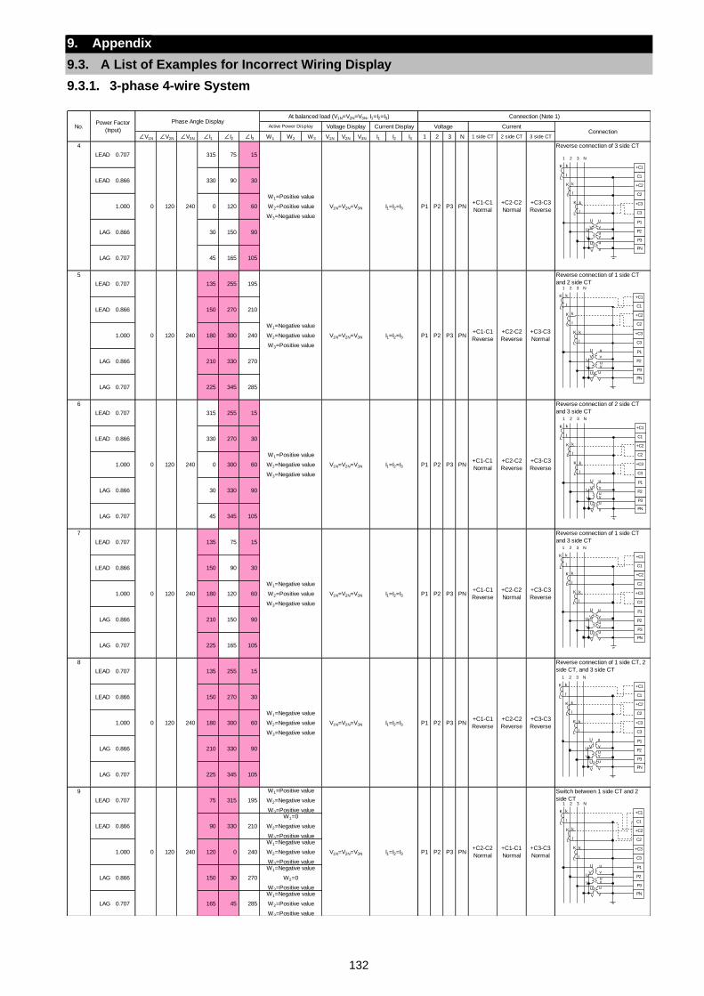
132
9. Appendix
9.3. A List of Examples for Incorrect Wiring Display
9.3.1. 3-phase 4-wire System
∠V1N ∠V2N ∠V3N ∠I1 ∠I2 ∠I3 W1 W2 W3 V1N V2N V3N I1 I2 I3 1 2 3 N 1 side CT 2 side CT 3 side CT
4
LEAD 0.707 315 75 15
Reverse connection of 3 side CT
LEAD 0.866 330 90 30
1.000 0 120 60
LAG 0.866 30 150 90
LAG 0.707 45 165 105
5
LEAD 0.707 135 255 195
Reverse connection of 1 side CT
and 2 side CT
LEAD 0.866 150 270 210
1.000 180 300 240
LAG 0.866 210 330 270
LAG 0.707 225 345 285
6
LEAD 0.707 315 255 15
Reverse connection of 2 side CT
and 3 side CT
LEAD 0.866 330 270 30
1.000 0 300 60
LAG 0.866 30 330 90
LAG 0.707 45 345 105
7
LEAD 0.707 135 75 15
Reverse connection of 1 side CT
and 3 side CT
LEAD 0.866 150 90 30
1.000 180 120 60
LAG 0.866 210 150 90
LAG 0.707 225 165 105
8
LEAD 0.707 135 255 15
Reverse connection of 1 side CT, 2
side CT, and 3 side CT
LEAD 0.866 150 270 30
1.000 180 300 60
LAG 0.866 210 330 90
LAG 0.707 225 345 105
9
LEAD 0.707 75 315 195
Switch between 1 side CT and 2
side CT
LEAD 0.866 90 330 210
1.000 120 0 240
LAG 0.866 150 30 270
LAG 0.707 165 45 285
+C2-C2
Normal
+C3-C3
Reverse0 120 240
W1=Positive value
W2=Positive value
W3=Negative value
V1N=V2N=V3N I1=I2=I3 P1 P2 P3
0 120
PN+C1-C1
Normal
V1N=V2N=V3N I1=I2=I3 P1 P2 P3 PN+C1-C1
Normal
+C2-C2
Reverse
+C3-C3
Reverse
+C2-C2
Normal
+C3-C3
Reverse
PN+C1-C1
Reverse
P3 PN+C1-C1
Reverse
+C2-C2
Reverse
+C3-C3
Normal
0 120 240
W1=Positive value
W2=Negative value
W3=Negative value
No.Power Factor
(Input)
Phase Angle DisplayAt balanced load (V1N=V2N=V3N, I1=I2=I3) Connection (Note 1)
Active Power Display Voltage Display Current Display Voltage CurrentConnection
PN+C1-C1
Reverse
0 120 240
W1=Negative value
W2=Negative value
W3=Positive value
V1N=V2N=V3N I1=I2=I3 P1 P2
240
W1=Negative value
W2=Negative value
W3=Negative value
V1N=V2N=V3N I1=I2=I3 P1 P2 P3
240
W1=Negative value
W2=Positive value
W3=Negative value
V1N=V2N=V3N I1=I2=I3 P1 P2 P3
+C2-C2
Reverse
+C3-C3
Reverse
0 120 240
W1=Positive value
W2=Negative value
W3=Positive value
V1N=V2N=V3N I1=I2=I3 P1 P2 P3 PN+C2-C2
Normal
+C1-C1
Normal
+C3-C3
Normal
W1=0
W2=Negative value
W3=Positive valueW1=Negative value
W2=Negative value
W3=Positive valueW1=Negative value
W2=0
W3=Positive valueW1=Negative value
W2=Positive value
W3=Positive value
0 120
+C2
C2
+C3
C3
P1
P3
P2
+C1
C1
PN
1 2 3 N
K
L
k
l
K
L
k
l
K
L
k
l
U u
V vU
V vu
v
uU
V
+C2
C2
+C3
C3
P1
P3
P2
+C1
C1
PN
1 2 3 N
K
L
k
l
K
L
k
l
K
L
k
l
U u
V vU
V vu
v
uU
V
+C2
C2
+C3
C3
P1
P3
P2
+C1
C1
PN
1 2 3 N
K
L
k
l
K
L
k
l
K
L
k
l
U u
V vU
V vu
v
uU
V
+C2
C2
+C3
C3
P1
P3
P2
+C1
C1
PN
1 2 3 N
K
L
k
l
K
L
k
l
K
L
k
l
U u
V vU
V vu
v
uU
V
+C2
C2
+C3
C3
P1
P3
P2
+C1
C1
PN
1 2 3 N
K
L
k
l
K
L
k
l
K
L
k
l
U u
V vU
V vu
v
uU
V
+C2
C2
+C3
C3
P1
P3
P2
+C1
C1
PN
1 2 3 N
K
L
k
l
K
L
k
l
K
L
k
l
U u
V vU
V vu
v
uU
V
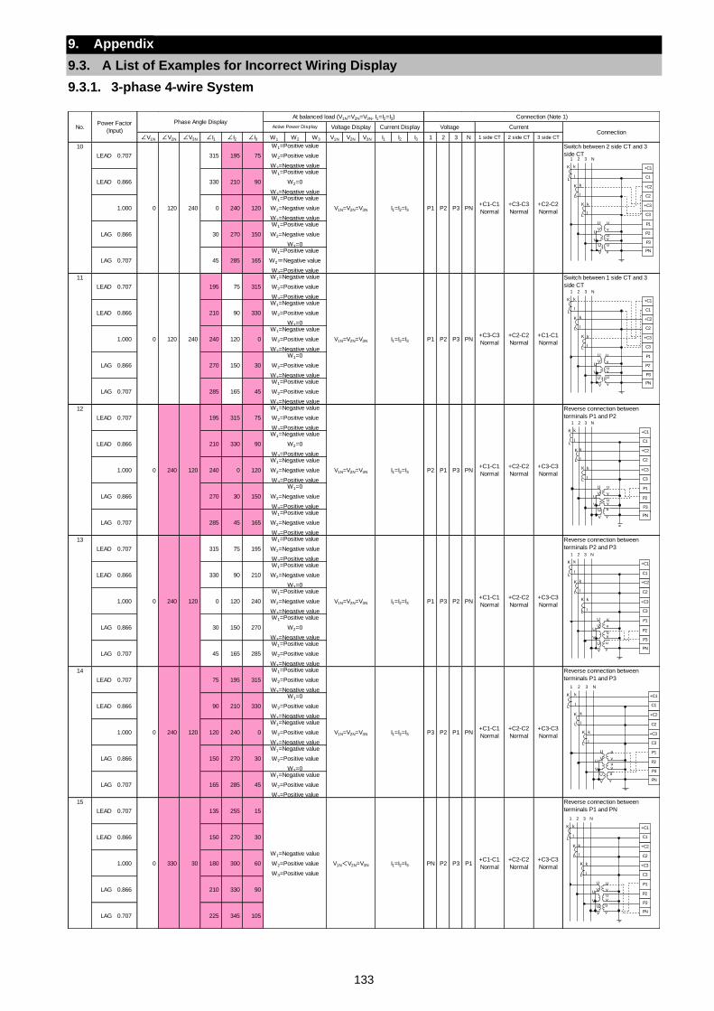
133
9. Appendix
9.3. A List of Examples for Incorrect Wiring Display
9.3.1. 3-phase 4-wire System
∠V1N ∠V2N ∠V3N ∠I1 ∠I2 ∠I3 W1 W2 W3 V1N V2N V3N I1 I2 I3 1 2 3 N 1 side CT 2 side CT 3 side CT
10
LEAD 0.707 315 195 75
Switch between 2 side CT and 3
side CT
LEAD 0.866 330 210 90
1.000 0 240 120
LAG 0.866 30 270 150
LAG 0.707 45 285 165
11
LEAD 0.707 195 75 315
Switch between 1 side CT and 3
side CT
LEAD 0.866 210 90 330
1.000 240 120 0
LAG 0.866 270 150 30
LAG 0.707 285 165 45
12
LEAD 0.707 195 315 75
Reverse connection between
terminals P1 and P2
LEAD 0.866 210 330 90
1.000 240 0 120
LAG 0.866 270 30 150
LAG 0.707 285 45 165
13
LEAD 0.707 315 75 195
Reverse connection between
terminals P2 and P3
LEAD 0.866 330 90 210
1.000 0 120 240
LAG 0.866 30 150 270
LAG 0.707 45 165 285
14
LEAD 0.707 75 195 315
Reverse connection between
terminals P1 and P3
LEAD 0.866 90 210 330
1.000 120 240 0
LAG 0.866 150 270 30
LAG 0.707 165 285 45
15
LEAD 0.707 135 255 15
Reverse connection between
terminals P1 and PN
LEAD 0.866 150 270 30
1.000 180 300 60
LAG 0.866 210 330 90
LAG 0.707 225 345 105
W1=Negative value
W2=Positive value
W3=Positive value
V1N<V2N=V3N I1=I2=I3
+C3-C3
Normal
W1=0
W2=Positive value
W3=Negative valueW1=Negative value
W2=Positive value
W3=Negative valueW1=Negative value
W2=Positive value
W3=0W1=Negative value
W2=Positive value
W3=Positive value
+C3-C3
NormalPN P2 P3 P1
+C1-C1
Normal
+C2-C2
Normal0 330 30
P3 P2 P1 PN+C1-C1
Normal
+C2-C2
Normal0 240 120
W1=Positive value
W2=Positive value
W3=Negative value
V1N=V2N=V3N I1=I2=I3
+C1-C1
Normal
+C2-C2
Normal
+C2-C2
Normal
+C3-C3
Normal
W1=Positive value
W2=Negative value
W3=0W1=Positive value
W2=Negative value
W3=Negative valueW1=Positive value
W2=0
W3=Negative valueW1=Positive value
W2=Positive value
W3=Negative value
I1=I2=I3 P1 P3 P2 PN+C1-C1
Normal
W1=Negative value
W2=0
W3=Positive valueW1=Negative value
W2=Negative value
W3=Positive valueW1=0
W2=Negative value
W3=Positive valueW1=Positive value
W2=Negative value
W3=Positive value
0 240 120
W1=Positive value
W2=Negative value
W3=Positive value
V1N=V2N=V3N
0 240 120
W1=Negative value
W2=Positive value
W3=Positive value
V1N=V2N=V3N I1=I2=I3+C3-C3
NormalP2 P1 P3 PN
P1 P2 P3
W1=Negative value
W2=Positive value
W3=0W1=Negative value
W2=Positive value
W3=Negative valueW1=0
W2=Positive value
W3=Negative value
0 120 240
W1=Positive value
W2=Positive value
W3=Negative value
V1N=V2N=V3N I1=I2=I3
V1N=V2N=V3N I1=I2=I3
W1=Positive value
W2=Negative value
W3=Negative valueW1=Positive value
W2=Negative value
W3=0W1=Positive value
W2=Negative value
W3=Positive value
0 120 240
W1=Negative value
W2=Positive value
W3=Positive value
P1 P2 P3 PN+C3-C3
Normal
+C2-C2
Normal
+C1-C1
Normal
W1=Positive value
W2=Positive value
W3=Negative value
No.Power Factor
(Input)
Phase Angle DisplayAt balanced load (V1N=V2N=V3N, I1=I2=I3) Connection (Note 1)
Active Power Display Voltage Display Current Display Voltage CurrentConnection
PN+C1-C1
Normal
+C3-C3
Normal
+C2-C2
Normal
W1=Positive value
W2=0
W3=Negative value
+C2
C2
+C3
C3
P1
P3
P2
+C1
C1
PN
1 2 3 N
K
L
k
l
K
L
k
l
K
L
k
l
U u
V vU
V vu
v
uU
V
+C2
C2
+C3
C3
P1
P3
P2
+C1
C1
PN
1 2 3 N
K
L
k
l
K
L
k
l
K
L
k
l
U u
V vU
V vu
v
uU
V
+C2
C2
+C3
C3
P1
P3
P2
+C1
C1
PN
1 2 3 N
K
L
k
l
K
L
k
l
K
L
k
l
U u
V vU
V vu
v
uU
V
+C2
C2
+C3
C3
P1
P3
P2
+C1
C1
PN
1 2 3 N
K
L
k
l
K
L
k
l
K
L
k
l
U u
V vU
V vu
v
uU
V
+C2
C2
+C3
C3
P1
P3
P2
+C1
C1
PN
1 2 3 N
K
L
k
l
K
L
k
l
K
L
k
l
U u
V vU
V vu
v
uU
V
+C2
C2
+C3
C3
P1
P3
P2
+C1
C1
PN
1 2 3 N
K
L
k
l
K
L
k
l
K
L
k
l
U u
V vU
V vu
v
uU
V
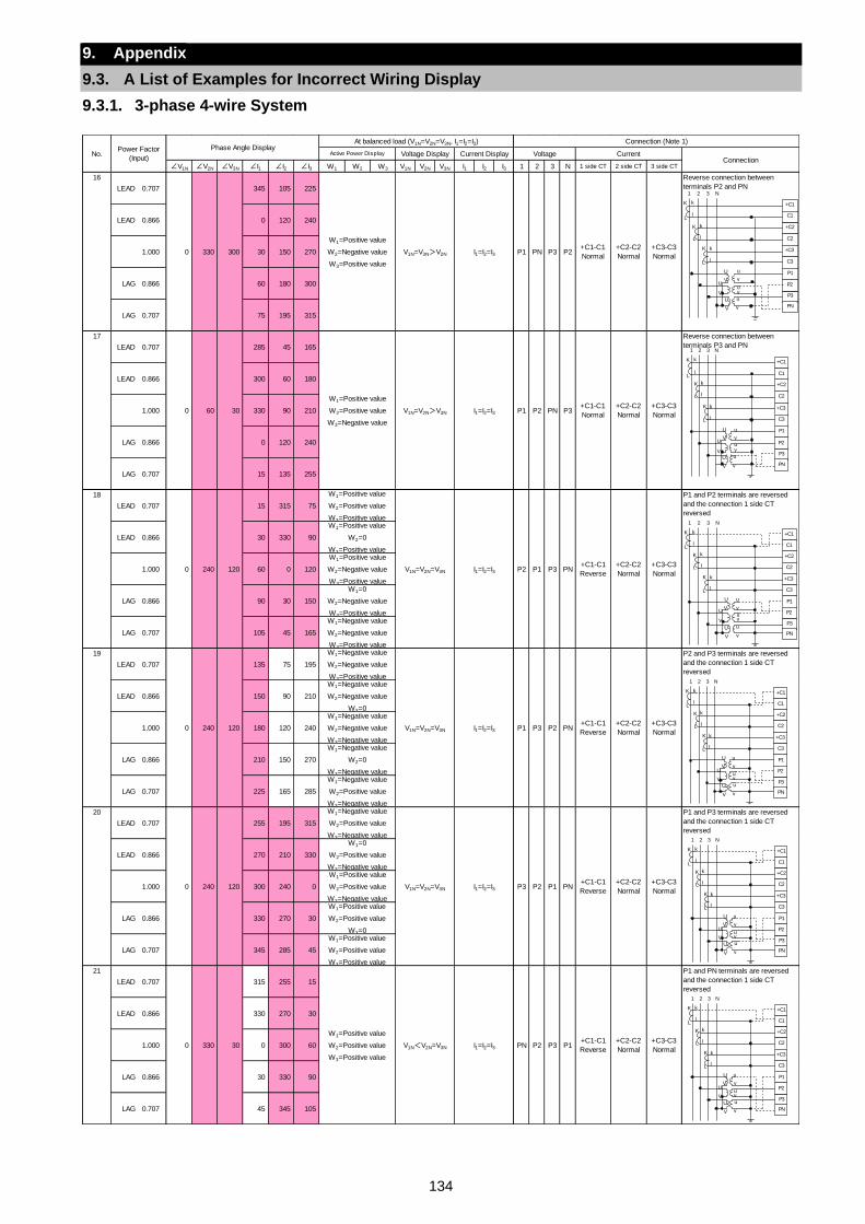
134
9. Appendix
9.3. A List of Examples for Incorrect Wiring Display
9.3.1. 3-phase 4-wire System
∠V1N ∠V2N ∠V3N ∠I1 ∠I2 ∠I3 W1 W2 W3 V1N V2N V3N I1 I2 I3 1 2 3 N 1 side CT 2 side CT 3 side CT
16
LEAD 0.707 345 105 225
Reverse connection between
terminals P2 and PN
LEAD 0.866 0 120 240
1.000 30 150 270
LAG 0.866 60 180 300
LAG 0.707 75 195 315
17
LEAD 0.707 285 45 165
Reverse connection between
terminals P3 and PN
LEAD 0.866 300 60 180
1.000 330 90 210
LAG 0.866 0 120 240
LAG 0.707 15 135 255
18
LEAD 0.707 15 315 75
P1 and P2 terminals are reversed
and the connection 1 side CT
reversed
LEAD 0.866 30 330 90
1.000 60 0 120
LAG 0.866 90 30 150
LAG 0.707 105 45 165
19
LEAD 0.707 135 75 195
P2 and P3 terminals are reversed
and the connection 1 side CT
reversed
LEAD 0.866 150 90 210
1.000 180 120 240
LAG 0.866 210 150 270
LAG 0.707 225 165 285
20
LEAD 0.707 255 195 315
P1 and P3 terminals are reversed
and the connection 1 side CT
reversed
LEAD 0.866 270 210 330
1.000 300 240 0
LAG 0.866 330 270 30
LAG 0.707 345 285 45
21
LEAD 0.707 315 255 15
P1 and PN terminals are reversed
and the connection 1 side CT
reversed
LEAD 0.866 330 270 30
1.000 0 300 60
LAG 0.866 30 330 90
LAG 0.707 45 345 105
W1=Positive value
W2=Positive value
W3=Positive value
V1N<V2N=V3N I1=I2=I3
+C3-C3
Normal
W1=0
W2=Positive value
W3=Negative valueW1=Positive value
W2=Positive value
W3=Negative valueW1=Positive value
W2=Positive value
W3=0W1=Positive value
W2=Positive value
W3=Positive value
+C3-C3
NormalPN P2 P3 P1
+C1-C1
Reverse
+C2-C2
Normal0 330 30
+C1-C1
Reverse
P3 P2 P1 PN+C1-C1
Reverse
+C2-C2
Normal0 240 120
W1=Negative value
W2=Positive value
W3=Negative value
V1N=V2N=V3N I1=I2=I3
W1=Negative value
W2=Negative value
W3=0W1=Negative value
W2=Negative value
W3=Negative valueW1=Negative value
W2=0
W3=Negative valueW1=Negative value
W2=Positive value
W3=Negative value
I1=I2=I3 P1 P3 P2 PN
+C3-C3
Normal
W1=Positive value
W2=0
W3=Positive valueW1=Positive value
W2=Negative value
W3=Positive valueW1=0
W2=Negative value
W3=Positive valueW1=Negative value
W2=Negative value
W3=Positive value
0 240 120
W1=Negative value
W2=Negative value
W3=Positive value
V1N=V2N=V3N
P2 P1 P3 PN+C1-C1
Reverse
+C2-C2
Normal0 240 120
W1=Positive value
W2=Positive value
W3=Positive value
V1N=V2N=V3N I1=I2=I3
+C2-C2
Normal
+C3-C3
Normal
No.Power Factor
(Input)
Phase Angle DisplayAt balanced load (V1N=V2N=V3N, I1=I2=I3) Connection (Note 1)
Active Power Display Voltage Display Current Display Voltage CurrentConnection
P2+C1-C1
Normal
+C2-C2
Normal
+C3-C3
Normal
0 60 30
W1=Positive value
W2=Positive value
W3=Negative value
V1N=V2N>V3N I1=I2=I3+C3-C3
NormalP1 P2 PN P3
+C1-C1
Normal
+C2-C2
Normal
0 330 300
W1=Positive value
W2=Negative value
W3=Positive value
V1N=V3N>V2N I1=I2=I3 P1 PN P3
+C2
C2
+C3
C3
P1
P3
P2
+C1
C1
PN
1 2 3 N
K
L
k
l
K
L
k
l
K
L
k
l
U u
V vU
V vu
v
uU
V
+C2
C2
+C3
C3
P1
P3
P2
+C1
C1
PN
1 2 3 N
K
L
k
l
K
L
k
l
K
L
k
l
U u
V vU
V vu
v
uU
V
+C2
C2
+C3
C3
P1
P3
P2
+C1
C1
PN
1 2 3 N
K
L
k
l
K
L
k
l
K
L
k
l
U u
V vU
V vu
v
uU
V
+C2
C2
+C3
C3
P1
P3
P2
+C1
C1
PN
1 2 3 N
K
L
k
l
K
L
k
l
K
L
k
l
U u
V vU
V vu
v
uU
V
+C2
C2
+C3
C3
P1
P3
P2
+C1
C1
PN
1 2 3 N
K
L
k
l
K
L
k
l
K
L
k
l
U u
V vU
V vu
v
uU
V
+C2
C2
+C3
C3
P1
P3
P2
+C1
C1
PN
1 2 3 N
K
L
k
l
K
L
k
l
K
L
k
l
U u
V vU
V vu
v
uU
V

135
9. Appendix
9.3. A List of Examples for Incorrect Wiring Display
9.3.1. 3-phase 4-wire System
∠V1N ∠V2N ∠V3N ∠I1 ∠I2 ∠I3 W1 W2 W3 V1N V2N V3N I1 I2 I3 1 2 3 N 1 side CT 2 side CT 3 side CT
22
LEAD 0.707 165 105 225
P2 and PN terminals are reversed
and the connection 1 side CT
reversed
LEAD 0.866 180 120 240
1.000 210 150 270
LAG 0.866 240 180 300
LAG 0.707 255 195 315
23
LEAD 0.707 105 45 165
P3 and PN terminals are reversed
and the connection 1 side CT
reversed
LEAD 0.866 120 60 180
1.000 150 90 210
LAG 0.866 180 120 240
LAG 0.707 195 135 255
24
LEAD 0.707 195 135 75
P1 and P2 terminals are reversed
and the connection 2 side CT
reversed
LEAD 0.866 210 150 90
1.000 240 180 120
LAG 0.866 270 210 150
LAG 0.707 285 225 165
25
LEAD 0.707 315 255 195
P1 and P2 terminals are reversed
and the connection 1 side CT
reversed
LEAD 0.866 330 270 210
1.000 0 300 240
LAG 0.866 30 330 270
LAG 0.707 45 345 285
26
LEAD 0.707 75 15 315
P1 and P3 terminals are reversed
and the connection 2 side CT
reversed
LEAD 0.866 90 30 330
1.000 120 60 0
LAG 0.866 150 90 30
LAG 0.707 165 105 45
27
LEAD 0.707 135 75 15
P1 and PN terminals are reversed
and the connection 2 side CT
reversed
LEAD 0.866 150 90 30
1.000 180 120 60
LAG 0.866 210 150 90
LAG 0.707 225 165 105
P1+C1-C1
Normal
+C2-C2
Reverse
+C3-C3
Normal0 330 30
W1=Negative value
W2=Negative value
W3=Positive value
V1N<V2N=V3N I1=I2=I3 PN P2 P3
+C1-C1
Normal
W1=0
W2=Negative value
W3=Negative valueW1=Negative value
W2=Negative value
W3=Negative valueW1=Negative value
W2=Negative value
W3=0W1=Negative value
W2=Negative value
W3=Positive value
I1=I2=I3 P3 P2 P10 240 120
W1=Positive value
W2=Negative value
W3=Negative value
V1N=V2N=V3N
P1 P3 P2 PN0 240 120
W1=Positive value
W2=Positive value
W3=Positive value
V1N=V2N=V3N I1=I2=I3
+C3-C3
Normal
PN+C1-C1
Normal
+C2-C2
Reverse
+C3-C3
Normal
W1=Negative value
W2=0
W3=Positive valueW1=Negative value
W2=Positive value
W3=Positive valueW1=0
W2=Positive value
W3=Positive valueW1=Positive value
W2=Positive value
W3=Positive value
PN
+C3-C3
Normal
W1=Positive value
W2=Positive value
W3=0W1=Positive value
W2=Positive value
W3=Negative valueW1=Positive value
W2=0
W3=Negative valueW1=Positive value
W2=Negative value
W3=Negative value
+C1-C1
Normal
+C2-C2
Reverse
+C2-C2
Reverse
0 240 120
W1=Negative value
W2=Negative value
W3=Positive value
V1N=V2N=V3N I1=I2=I3 P2 P1 P3
P2+C1-C1
Reverse
+C2-C2
Normal
+C3-C3
Normal
0 60 30
W1=Negative value
W2=Positive value
W3=Negative value
V1N=V2N>V3N I1=I2=I3+C3-C3
NormalP1 P2 PN P3
+C1-C1
Reverse
+C2-C2
Normal
0 330 300
W1=Negative value
W2=Negative value
W3=Positive value
V1N=V3N>V2N I1=I2=I3 P1 PN P3
No.Power Factor
(Input)
Phase Angle DisplayAt balanced load (V1N=V2N=V3N, I1=I2=I3) Connection (Note 1)
Active Power Display Voltage Display Current Display Voltage CurrentConnection
+C2
C2
+C3
C3
P1
P3
P2
+C1
C1
PN
1 2 3 N
K
L
k
l
K
L
k
l
K
L
k
l
U u
V vU
V vu
v
uU
V
+C2
C2
+C3
C3
P1
P3
P2
+C1
C1
PN
1 2 3 N
K
L
k
l
K
L
k
l
K
L
k
l
U u
V vU
V vu
v
uU
V
+C2
C2
+C3
C3
P1
P3
P2
+C1
C1
PN
1 2 3 N
K
L
k
l
K
L
k
l
K
L
k
l
U u
V vU
V vu
v
uU
V
+C2
C2
+C3
C3
P1
P3
P2
+C1
C1
PN
1 2 3 N
K
L
k
l
K
L
k
l
K
L
k
l
U u
V vU
V vu
v
uU
V
+C2
C2
+C3
C3
P1
P3
P2
+C1
C1
PN
1 2 3 N
K
L
k
l
K
L
k
l
K
L
k
l
U u
V vU
V vu
v
uU
V
+C2
C2
+C3
C3
P1
P3
P2
+C1
C1
PN
1 2 3 N
K
L
k
l
K
L
k
l
K
L
k
l
U u
V vU
V vu
v
uU
V
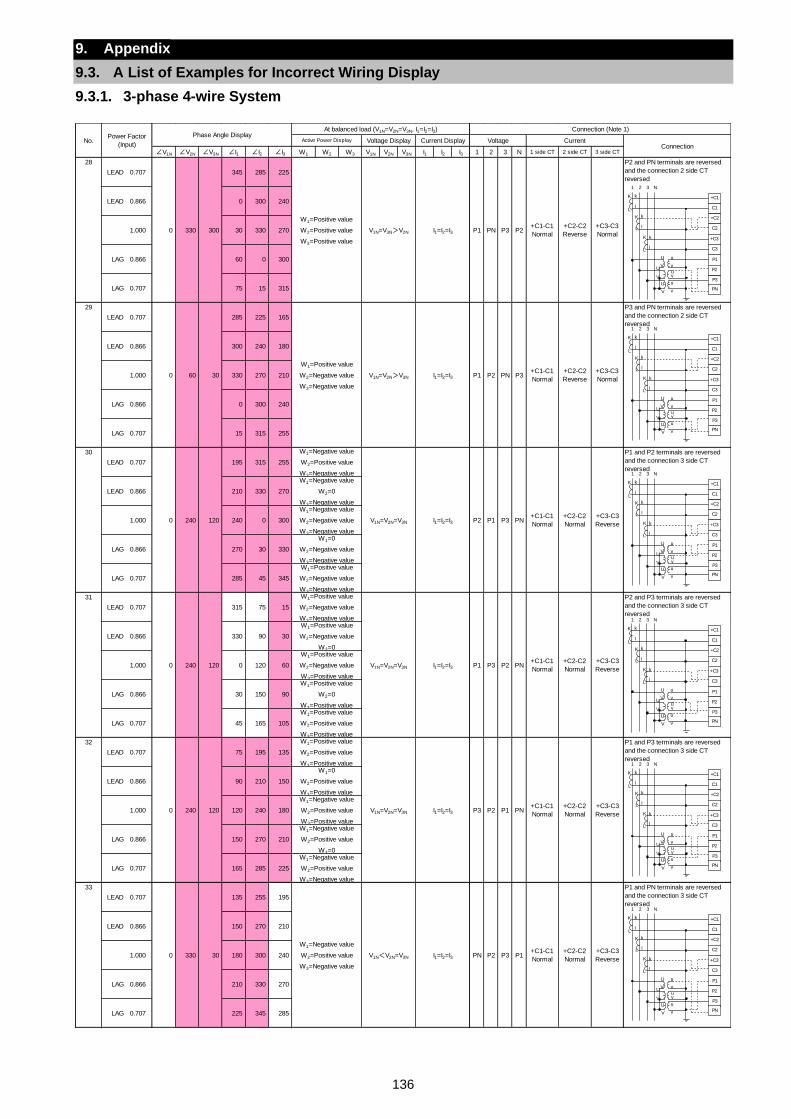
136
9. Appendix
9.3. A List of Examples for Incorrect Wiring Display
9.3.1. 3-phase 4-wire System
∠V1N ∠V2N ∠V3N ∠I1 ∠I2 ∠I3 W1 W2 W3 V1N V2N V3N I1 I2 I3 1 2 3 N 1 side CT 2 side CT 3 side CT
28
LEAD 0.707 345 285 225
P2 and PN terminals are reversed
and the connection 2 side CT
reversed
LEAD 0.866 0 300 240
1.000 30 330 270
LAG 0.866 60 0 300
LAG 0.707 75 15 315
29
LEAD 0.707 285 225 165
P3 and PN terminals are reversed
and the connection 2 side CT
reversed
LEAD 0.866 300 240 180
1.000 330 270 210
LAG 0.866 0 300 240
LAG 0.707 15 315 255
30
LEAD 0.707 195 315 255
P1 and P2 terminals are reversed
and the connection 3 side CT
reversed
LEAD 0.866 210 330 270
1.000 240 0 300
LAG 0.866 270 30 330
LAG 0.707 285 45 345
31
LEAD 0.707 315 75 15
P2 and P3 terminals are reversed
and the connection 3 side CT
reversed
LEAD 0.866 330 90 30
1.000 0 120 60
LAG 0.866 30 150 90
LAG 0.707 45 165 105
32
LEAD 0.707 75 195 135
P1 and P3 terminals are reversed
and the connection 3 side CT
reversed
LEAD 0.866 90 210 150
1.000 120 240 180
LAG 0.866 150 270 210
LAG 0.707 165 285 225
33
LEAD 0.707 135 255 195
P1 and PN terminals are reversed
and the connection 3 side CT
reversed
LEAD 0.866 150 270 210
1.000 180 300 240
LAG 0.866 210 330 270
LAG 0.707 225 345 285
V1N<V2N=V3N I1=I2=I3
W1=0
W2=Positive value
W3=Positive valueW1=Negative value
W2=Positive value
W3=Positive valueW1=Negative value
W2=Positive value
W3=0W1=Negative value
W2=Positive value
W3=Negative value
+C3-C3
ReversePN P2 P3 P1
+C1-C1
Normal
+C2-C2
Normal0 330 30
W1=Negative value
W2=Positive value
W3=Negative value
P3 P2 P1 PN+C1-C1
Normal
+C2-C2
Normal0 240 120
W1=Positive value
W2=Positive value
W3=Positive value
V1N=V2N=V3N I1=I2=I3+C3-C3
Reverse
+C2-C2
Normal
+C3-C3
Reverse
W1=Positive value
W2=Negative value
W3=0W1=Positive value
W2=Negative value
W3=Positive valueW1=Positive value
W2=0
W3=Positive valueW1=Positive value
W2=Positive value
W3=Positive value
I1=I2=I3 P1 P3 P2 PN+C1-C1
Normal0 240 120
W1=Positive value
W2=Negative value
W3=Negative value
V1N=V2N=V3N
P2 P1 P3 PN
P3+C1-C1
Normal
+C2-C2
Reverse
+C3-C3
Normal
0 240 120
W1=Negative value
W2=Positive value
W3=Negative value
V1N=V2N=V3N I1=I2=I3+C3-C3
Reverse
W1=Negative value
W2=0
W3=Negative valueW1=Negative value
W2=Negative value
W3=Negative valueW1=0
W2=Negative value
W3=Negative valueW1=Positive value
W2=Negative value
W3=Negative value
+C1-C1
Normal
+C2-C2
Normal
0 60 30
W1=Positive value
W2=Negative value
W3=Negative value
V1N=V2N>V3N I1=I2=I3 P1 P2 PN
0 330 300
W1=Positive value
W2=Positive value
W3=Positive value
V1N=V3N>V2N I1=I2=I3+C3-C3
NormalP1 PN P3 P2
+C1-C1
Normal
+C2-C2
Reverse
No.Power Factor
(Input)
Phase Angle DisplayAt balanced load (V1N=V2N=V3N, I1=I2=I3) Connection (Note 1)
Active Power Display Voltage Display Current Display Voltage CurrentConnection
+C2
C2
+C3
C3
P1
P3
P2
+C1
C1
PN
1 2 3 N
K
L
k
l
K
L
k
l
K
L
k
l
U u
V vU
V vu
v
uU
V
+C2
C2
+C3
C3
P1
P3
P2
+C1
C1
PN
1 2 3 N
K
L
k
l
K
L
k
l
K
L
k
l
U u
V vU
V vu
v
uU
V
+C2
C2
+C3
C3
P1
P3
P2
+C1
C1
PN
1 2 3 N
K
L
k
l
K
L
k
l
K
L
k
l
U u
V vU
V vu
v
uU
V
+C2
C2
+C3
C3
P1
P3
P2
+C1
C1
PN
1 2 3 N
K
L
k
l
K
L
k
l
K
L
k
l
U u
V vU
V vu
v
uU
V
+C2
C2
+C3
C3
P1
P3
P2
+C1
C1
PN
1 2 3 N
K
L
k
l
K
L
k
l
K
L
k
l
U u
V vU
V vu
v
uU
V
+C2
C2
+C3
C3
P1
P3
P2
+C1
C1
PN
1 2 3 N
K
L
k
l
K
L
k
l
K
L
k
l
U u
V vU
V vu
v
uU
V
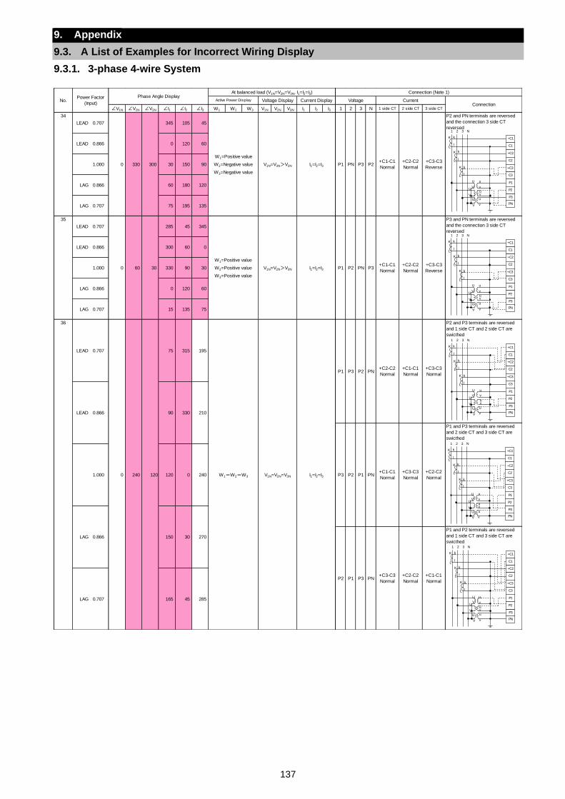
137
9. Appendix
9.3. A List of Examples for Incorrect Wiring Display
9.3.1. 3-phase 4-wire System
∠V1N ∠V2N ∠V3N ∠I1 ∠I2 ∠I3 W1 W2 W3 V1N V2N V3N I1 I2 I3 1 2 3 N 1 side CT 2 side CT 3 side CT
34
LEAD 0.707 345 105 45
P2 and PN terminals are reversed
and the connection 3 side CT
reversed
LEAD 0.866 0 120 60
1.000 30 150 90
LAG 0.866 60 180 120
LAG 0.707 75 195 135
35
LEAD 0.707 285 45 345
P3 and PN terminals are reversed
and the connection 3 side CT
reversed
LEAD 0.866 300 60 0
1.000 330 90 30
LAG 0.866 0 120 60
LAG 0.707 15 135 75
36 P2 and P3 terminals are reversed
and 1 side CT and 2 side CT are
swicthed
P1 and P3 terminals are reversed
and 2 side CT and 3 side CT are
swicthed
P1 and P2 terminals are reversed
and 1 side CT and 3 side CT are
swicthed
P2 P1 P3
+C1-C1
Normal
+C3-C3
Normal
+C2-C2
Normal1.000 120 0 240
LAG 0.866
+C2-C2
Normal
+C1-C1
Normal
+C3-C3
Normal
LEAD 0.866 90 330 210
P3 P2V1N=V2N=V3N I1=I2=I3
P1 P3 P2 PN
P1 PN
PN+C3-C3
Normal
+C2-C2
Normal
+C1-C1
Normal
LAG 0.707
LEAD 0.707
0 240 120
75 315 195
W1=W2=W3
165 45 285
150 30 270
P2+C1-C1
Normal
+C2-C2
Normal
+C3-C3
Reverse
0 60 30
W1=Positive value
W2=Positive value
W3=Positive value
V1N=V2N>V3N I1=I2=I3+C3-C3
ReverseP1 P2 PN P3
+C1-C1
Normal
+C2-C2
Normal
0 330 300
W1=Positive value
W2=Negative value
W3=Negative value
V1N=V3N>V2N I1=I2=I3 P1 PN P3
No.Power Factor
(Input)
Phase Angle DisplayAt balanced load (V1N=V2N=V3N, I1=I2=I3) Connection (Note 1)
Active Power Display Voltage Display Current Display Voltage CurrentConnection
+C2
C2
+C3
C3
P1
P3
P2
+C1
C1
PN
1 2 3 N
K
L
k
l
K
L
k
l
K
L
k
l
U u
V vU
V vu
v
uU
V
+C2
C2
+C3
C3
P1
P3
P2
+C1
C1
PN
1 2 3 N
K
L
k
l
K
L
k
l
K
L
k
l
U u
V vU
V vu
v
uU
V
+C2
C2
+C3
C3
P1
P3
P2
+C1
C1
PN
1 2 3 N
K
L
k
l
K
L
k
l
K
L
k
l
U u
V vU
V vu
v
uU
V
+C2
C2
+C3
C3
P1
P3
P2
+C1
C1
PN
1 2 3 N
K
L
k
l
K
L
k
l
K
L
k
l
U u
V vU
V vu
v
uU
V
+C2
C2
+C3
C3
P1
P3
P2
+C1
C1
PN
1 2 3 N
K
L
k
l
K
L
k
l
K
L
k
l
U u
V vU
V vu
v
uU
V
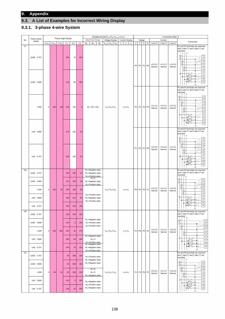
138
9. Appendix
9.3. A List of Examples for Incorrect Wiring Display
9.3.1. 3-phase 4-wire System
∠V1N ∠V2N ∠V3N ∠I1 ∠I2 ∠I3 W1 W2 W3 V1N V2N V3N I1 I2 I3 1 2 3 N 1 side CT 2 side CT 3 side CT
37 P1 and P3 terminals are reversed
and 1 side CT and 2 side CT are
swicthed
P1 and P2 terminals are reversed
and 2 side CT and 3 side CT are
swicthed
P2 and P3 terminals are reversed
and 1 side CT and 3 side CT are
swicthed
38
LEAD 0.707 255 135 15
P1 and PN terminals are reversed
and 1 side CT and 2 side CT are
swicthed
LEAD 0.866 270 150 30
1.000 300 180 60
LAG 0.866 330 210 90
LAG 0.707 345 225 105
39
LEAD 0.707 105 345 225
P2 and PN terminals are reversed
and 1 side CT and 2 side CT are
swicthed
LEAD 0.866 120 0 240
1.000 150 30 270
LAG 0.866 180 60 300
LAG 0.707 195 75 315
40
LEAD 0.707 45 285 165
P3 and PN terminals are reversed
and 1 side CT and 2 side CT are
swicthed
LEAD 0.866 60 300 180
1.000 90 330 210
LAG 0.866 120 0 240
LAG 0.707 135 15 255
+C2-C2
Normal
+C1-C1
Normal
+C3-C3
Normal
W1=0
W2=0
W3=Negative value
W1=Negative value
W2=Positive value
W3=Negative value
PN P3V1N=V2N>V3N I1=I2=I3 P1 P2
W1=Negative value
W2=0
W3=Positive valueW1=Negative value
W2=Negative value
W3=Positive value
0 60 30
W1=Positive value
W2=Negative value
W3=Negative value
PN P3 P2+C2-C2
Normal
+C1-C1
Normal
+C3-C3
Normal
+C3-C3
Normal
W1=0
W2=Negative value
W3=Positive value
W1=Positive value
W2=Negative value
W3=Positive value
0 330 300
W1=Negative value
W2=Positive value
W3=Positive value
V1N=V3N>V2N I1=I2=I3 P1
PN P2 P3 P1+C2-C2
Normal
+C1-C1
Normal0 330 30
W1=Negative value
W2=Negative value
W3=Positive value
V1N<V2N=V3N
P3
LAG
I1=I2=I3
30
P1 P3 PN+C1-C1
Normal
+C3-C3
Normal
+C2-C2
Normal
LAG 0.707 285
+C1-C1
Normal
+C3-C3
Normal
75 315
W1=W2=W3 V1N=V2N=V3N I1=I2=I3
P3
90 330
P2
P1 P2 PN+C3-C3
Normal
+C2-C2
Normal
+C1-C1
Normal
120 0
150
165 45
1.000 240
0.866 270
P2 P1 PN+C2-C2
Normal
LEAD 0.707
0 240 120
195
LEAD 0.866 210
No.Power Factor
(Input)
Phase Angle DisplayAt balanced load (V1N=V2N=V3N, I1=I2=I3) Connection (Note 1)
Active Power Display Voltage Display Current Display Voltage CurrentConnection
+C2
C2
+C3
C3
P1
P3
P2
+C1
C1
PN
1 2 3 N
K
L
k
l
K
L
k
l
K
L
k
l
U u
V vU
V vu
v
uU
V
+C2
C2
+C3
C3
P1
P3
P2
+C1
C1
PN
1 2 3 N
K
L
k
l
K
L
k
l
K
L
k
l
U u
V vU
V vu
v
uU
V
+C2
C2
+C3
C3
P1
P3
P2
+C1
C1
PN
1 2 3 N
K
L
k
l
K
L
k
l
K
L
k
l
U u
V vU
V vu
v
uU
V
+C2
C2
+C3
C3
P1
P3
P2
+C1
C1
PN
1 2 3 N
K
L
k
l
K
L
k
l
K
L
k
l
U u
V vU
V vu
v
uU
V
+C2
C2
+C3
C3
P1
P3
P2
+C1
C1
PN
1 2 3 N
K
L
k
l
K
L
k
l
K
L
k
l
U u
V vU
V vu
v
uU
V
+C2
C2
+C3
C3
P1
P3
P2
+C1
C1
PN
1 2 3 N
K
L
k
l
K
L
k
l
K
L
k
l
U u
V vU
V vu
v
uU
V
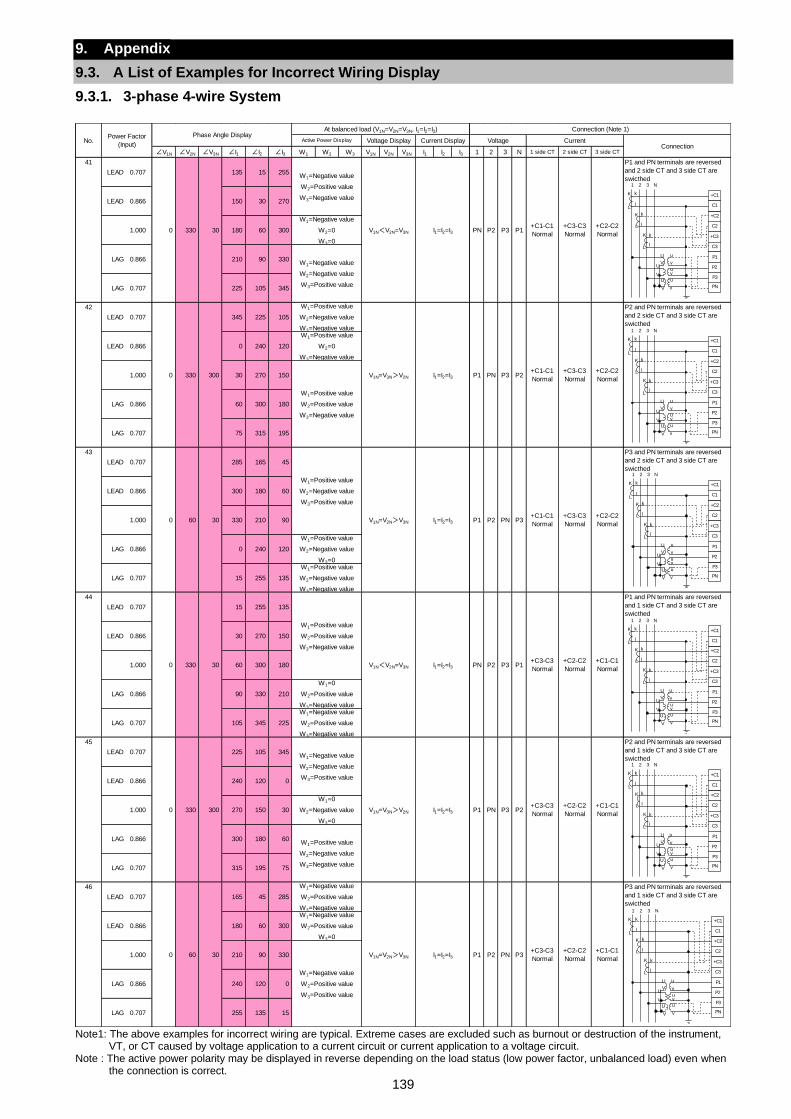
139
9. Appendix
9.3. A List of Examples for Incorrect Wiring Display
9.3.1. 3-phase 4-wire System
Note1: The above examples for incorrect wiring are typical. Extreme cases are excluded such as burnout or destruction of the instrument,
VT, or CT caused by voltage application to a current circuit or current application to a voltage circuit. Note : The active power polarity may be displayed in reverse depending on the load status (low power factor, unbalanced load) even when
the connection is correct.
∠V1N ∠V2N ∠V3N ∠I1 ∠I2 ∠I3 W1 W2 W3 V1N V2N V3N I1 I2 I3 1 2 3 N 1 side CT 2 side CT 3 side CT
41
LEAD 0.707 135 15 255
P1 and PN terminals are reversed
and 2 side CT and 3 side CT are
swicthed
LEAD 0.866 150 30 270
1.000 180 60 300
LAG 0.866 210 90 330
LAG 0.707 225 105 345
42
LEAD 0.707 345 225 105
P2 and PN terminals are reversed
and 2 side CT and 3 side CT are
swicthed
LEAD 0.866 0 240 120
1.000 30 270 150
LAG 0.866 60 300 180
LAG 0.707 75 315 195
43
LEAD 0.707 285 165 45
P3 and PN terminals are reversed
and 2 side CT and 3 side CT are
swicthed
LEAD 0.866 300 180 60
1.000 330 210 90
LAG 0.866 0 240 120
LAG 0.707 15 255 135
44
LEAD 0.707 15 255 135
P1 and PN terminals are reversed
and 1 side CT and 3 side CT are
swicthed
LEAD 0.866 30 270 150
1.000 60 300 180
LAG 0.866 90 330 210
LAG 0.707 105 345 225
45
LEAD 0.707 225 105 345
P2 and PN terminals are reversed
and 1 side CT and 3 side CT are
swicthed
LEAD 0.866 240 120 0
1.000 270 150 30
LAG 0.866 300 180 60
LAG 0.707 315 195 75
46
LEAD 0.707 165 45 285
P3 and PN terminals are reversed
and 1 side CT and 3 side CT are
swicthed
LEAD 0.866 180 60 300
1.000 210 90 330
LAG 0.866 240 120 0
LAG 0.707 255 135 15
+C1-C1
Normal
W1=Negative value
W2=Positive value
W3=0
W1=Negative value
W2=Positive value
W3=Positive value
V1N=V2N>V3N I1=I2=I3 P1 P2 PN P3+C3-C3
Normal
+C2-C2
Normal
0 330 300
W1=Negative value
W2=Negative value
W3=Positive value
V1N=V3N>V2N I1=I2=I3 P1
0 330 30
W1=Positive value
W2=Positive value
W3=Negative value
V1N<V2N=V3N
W1=0
W2=Negative value
W3=0
W1=Positive value
W2=Negative value
W3=Negative value
I1=I2=I3
0 60 30
W1=Negative value
W2=Positive value
W3=Negative value
W1=Positive value
W2=Negative value
W3=Negative value
+C2-C2
Normal
+C3-C3
Normal
+C2-C2
Normal
+C1-C1
Normal
+C1-C1
Normal
W1=0
W2=Positive value
W3=Negative valueW1=Negative value
W2=Positive value
W3=Negative value
P3 P1+C3-C3
Normal
+C2-C2
NormalPN P2
PN P3 P2
P2 PN P3+C1-C1
Normal
+C3-C3
Normal
W1=Positive value
W2=0
W3=Negative value
W1=Positive value
W2=Positive value
W3=Negative value
0 60 30
W1=Positive value
W2=Negative value
W3=Positive value
V1N=V2N>V3N I1=I2=I3 P1
P1 PN P3 P2+C1-C1
Normal
+C3-C3
Normal0 330 300
W1=Positive value
W2=Negative value
W3=0
W1=Positive value
W2=Negative value
W3=Negative value
V1N=V3N>V2N I1=I2=I3
I1=I2=I3 PN P2+C3-C3
Normal
+C2-C2
NormalP3 P1
+C1-C1
Normal
+C2-C2
Normal
0 330 30
W1=Negative value
W2=Positive value
W3=Negative value
V1N<V2N=V3N
W1=Negative value
W2=0
W3=0
W1=Negative value
W2=Negative value
W3=Positive value
No.Power Factor
(Input)
Phase Angle DisplayAt balanced load (V1N=V2N=V3N, I1=I2=I3) Connection (Note 1)
Active Power Display Voltage Display Current Display Voltage CurrentConnection
+C2
C2
+C3
C3
P1
P3
P2
+C1
C1
PN
1 2 3 N
K
L
k
l
K
L
k
l
K
L
k
l
U u
V vU
V vu
v
uU
V
+C2
C2
+C3
C3
P1
P3
P2
+C1
C1
PN
1 2 3 N
K
L
k
l
K
L
k
l
K
L
k
l
U u
V vU
V vu
v
uU
V
+C2
C2
+C3
C3
P1
P3
P2
+C1
C1
PN
1 2 3 N
K
L
k
l
K
L
k
l
K
L
k
l
U u
V vU
V vu
v
uU
V
+C2
C2
+C3
C3
P1
P3
P2
+C1
C1
PN
1 2 3 N
K
L
k
l
K
L
k
l
K
L
k
l
U u
V vU
V vu
v
uU
V
+C2
C2
+C3
C3
P1
P3
P2
+C1
C1
PN
1 2 3 N
K
L
k
l
K
L
k
l
K
L
k
l
U u
V vU
V vu
v
uU
V
+C2
C2
+C3
C3
P1
P3
P2
+C1
C1
PN
1 2 3 N
K
L
k
l
K
L
k
l
K
L
k
l
U u
V vU
V vu
v
uU
V
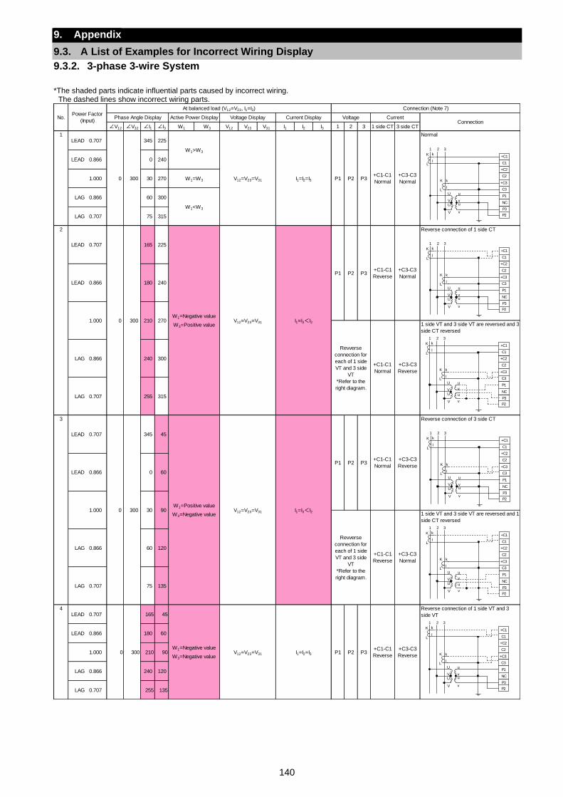
140
9. Appendix
9.3. A List of Examples for Incorrect Wiring Display
9.3.2. 3-phase 3-wire System
*The shaded parts indicate influential parts caused by incorrect wiring.
The dashed lines show incorrect wiring parts.
∠V12 ∠V32 ∠I1 ∠I3 W1 W3 V12 V23 V31 I1 I2 I3 1 2 3 1 side CT 3 side CT
1LEAD 0.707 345 225
Normal
LEAD 0.866 0 240
1.000 30 270
LAG 0.866 60 300
LAG 0.707 75 315
2 Reverse connection of 1 side CT
1 side VT and 3 side VT are reversed and 3
side CT reversed
3 Reverse connection of 3 side CT
1 side VT and 3 side VT are reversed and 1
side CT reversed
4LEAD 0.707 165 45
Reverse connection of 1 side VT and 3
side VT
LEAD 0.866 180 60
1.000 210 90
LAG 0.866 240 120
LAG 0.707 255 135
No.Power Factor
(Input)
At balanced load (V12=V23, I1=I3) Connection (Note 7)
Phase Angle Display Active Power Display Voltage Display Current Display Voltage CurrentConnection
0 300
W1>W3
V12=V23=V31 I1=I2=I3 P1 P2 P3+C1-C1
Normal
+C3-C3
NormalW1=W3
W1<W3
LEAD 0.707
0 300
165 225
W1=Negative value
W3=Positive value
+C3-C3
Normal
LEAD 0.866 180 240
1.000 210 270
Revverse
connection for
each of 1 side
VT and 3 side
VT
*Refer to the
right diagram.
V12=V23=V31 I1=I3<I2
P1 P2 P3+C1-C1
Reverse
+C1-C1
Normal
+C3-C3
Reverse
LAG 0.866 240 300
LAG 0.707 255 315
+C1-C1
Normal
+C3-C3
Reverse
LEAD 0.866 0 60
1.000 30 90W1=Positive value
W3=Negative valueV12=V23=V31 I1=I3<I2
P1 P2 P3
Revverse
connection for
each of 1 side
VT and 3 side
VT
*Refer to the
right diagram.
LEAD 0.707
0 300
345 45
+C1-C1
Reverse
+C3-C3
Normal
LAG 0.866 60 120
LAG 0.707 75 135
0 300W1=Negative value
W3=Negative valueV12=V23=V31 I1=I2=I3 P1 P2 P3
+C1-C1
Reverse
+C3-C3
Reverse
+C2
C2
+C3
C3
P1
P3
NC
+C1
C1
P2
K
L
k
l
K
L
k
l
U u
V vU u
V v
1 2 3
+C2
C2
+C3
C3
P1
P3
NC
+C1
C1
P2
K
L
k
l
K
L
k
l
U u
V vU u
V v
1 2 3
+C2
C2
+C3
C3
P1
P3
NC
+C1
C1
P2
K
L
k
l
K
L
k
l
U u
V vU u
V v
1 2 3
+C2
C2
+C3
C3
P1
P3
NC
+C1
C1
P2
K
L
k
l
K
L
k
l
U u
V v
U u
V v
1 2 3
+C2
C2
+C3
C3
P1
P3
NC
+C1
C1
P2
K
L
k
l
K
L
k
l
U u
V v
U u
V v
1 2 3
+C2
C2
+C3
C3
P1
P3
NC
+C1
C1
P2
K
L
k
l
K
L
k
l
U u
V vU u
V v
1 2 3
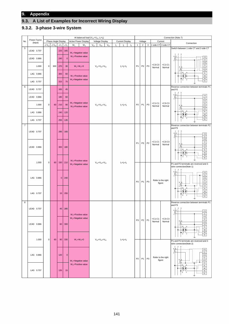
141
9. Appendix
9.3. A List of Examples for Incorrect Wiring Display
9.3.2. 3-phase 3-wire System
∠V12 ∠V32 ∠I1 ∠I3 W1 W3 V12 V23 V31 I1 I2 I3 1 2 3 1 side CT 3 side CT
5LEAD 0.707 225 345
Switch between 1 side CT and 3 side CT
LEAD 0.866 240 0
1.000 270 30
LAG 0.866 300 60
LAG 0.707 315 75
6LEAD 0.707 165 45
Reverse connection between terminals P1
and P2
LEAD 0.866 180 60
1.000 210 90
LAG 0.866 240 120
LAG 0.707 255 135
7 Reverse connection between terminals P2
and P3
P1 and P2 terminals are reversed and 3
wire connection(Note 1)
8 Reverse connection between terminals P1
and P3
P1 and P2 terminals are reversed and 3
wire connection(Note 2)
No.Power Factor
(Input)
At balanced load (V12=V23, I1=I3) Connection (Note 7)
Phase Angle Display Active Power DisplayConnection
0 300
W1=Negative value
W3=Positive value
V12=V23=V31 I1=I2=I3 P1 P2 P3+C3-C3
Normal
+C1-C1
NormalW1=W3=0
W1=Positive value
W3=Negative value
Voltage Display Current Display Voltage Current
P1 P3+C1-C1
Normal
+C3-C3
Normal
LEAD 0.707
0 60
285 165
0 60W1=Negative value
W3=Positive valueV12=V23=V31 I1=I2=I3 P2
+C1-C1
Normal
+C3-C3
Normal
LEAD 0.866 300 180
1.000
I1=I2=I3
P3 P2 P1
W1=W3=0
P2 P1 P3
LEAD 0.707
0 60
Refer to the right
figure
LAG 0.866 0 240
LAG 0.707 15 255
330 210W1=Positive value
W3=Negative valueV12=V23=V31 I1=I2=I3
P1 P3 P2
P2 P1 P3
45 285
Refer to the right
figure
LAG 0.866 120 0
W1=Negative value
W3=Positive value
LAG 0.707 135 15
+C1-C1
Normal
+C3-C3
Normal
LEAD 0.866 60 300
1.000 90 330
W1=Positive value
W3=Negative value
V12=V23=V31
+C2
C2
+C3
C3
P1
P3
NC
+C1
C1
P2
K
L
k
l
K
L
k
l
U u
V vU u
V v
1 2 3
+C2
C2
+C3
C3
P1
P3
NC
+C1
C1
P2
K
L
k
l
K
L
k
l
U u
V vU u
V v
1 2 3
+C2
C2
+C3
C3
P1
P3
NC
+C1
C1
P2
K
L
k
l
K
L
k
l
U u
V vU u
V v
1 2 3
+C2
C2
+C3
C3
P1
P3
NC
+C1
C1
P2
K
L
k
l
K
L
k
l
U u
V vU u
V v
1 2 3
+C2
C2
+C3
C3
P1
P3
NC
+C1
C1
P2
K
L
k
l
K
L
k
l
U u
V vU u
V v
1 2 3
+C2
C2
+C3
C3
P1
P3
NC
+C1
C1
P2
K
L
k
l
K
L
k
l
U u
V vU u
V v
1 2 3
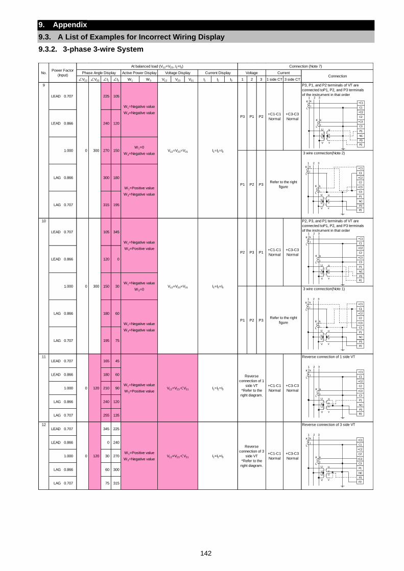
142
9. Appendix
9.3. A List of Examples for Incorrect Wiring Display
9.3.2. 3-phase 3-wire System
∠V12 ∠V32 ∠I1 ∠I3 W1 W3 V12 V23 V31 I1 I2 I3 1 2 3 1 side CT 3 side CT
9 P3, P1, and P2 terminals of VT are
connected toP1, P2, and P3 terminals
of the instrument in that order
3 wire connection(Note 2)
10 P2, P3, and P1 terminals of VT are
connected toP1, P2, and P3 terminals
of the instrument in that order
3 wire connection(Note 1)
11LEAD 0.707 165 45
Reverse connection of 1 side VT
LEAD 0.866 180 60
1.000 210 90
LAG 0.866 240 120
LAG 0.707 255 135
12LEAD 0.707 345 225
Reverse connection of 3 side VT
LEAD 0.866 0 240
1.000 30 270
LAG 0.866 60 300
LAG 0.707 75 315
No.Power Factor
(Input)
At balanced load (V12=V23, I1=I3) Connection (Note 7)
Phase Angle Display Active Power Display Voltage Display Current Display Voltage Current
LEAD 0.866 240 120
Connection
LEAD 0.707
0 300
225 105
W1=Negative value
W3=Negative value
V12=V23=V31 I1=I2=I3
105 345
P3Refer to the right
figure
LAG 0.866 300 180
W1=Positive value
W3=Negative value
LAG 0.707 315
1.000 270 150W1=0
W3=Negative value
P1 P2
195
P3 P1 P2+C1-C1
Normal
+C3-C3
Normal
+C1-C1
Normal
+C3-C3
Normal
LEAD 0.866 120 0
1.000 150 30
W1=Negative value
W3=Positive value
V12=V23=V31 I1=I2=I3
P2 P3 P1
W1=Negative value
W3=0
P1 P2 P3
LEAD 0.707
0 300
Refer to the right
figure
LAG 0.866 180 60
W1=Negative value
W3=Negative value
LAG 0.707 195 75
+C1-C1
Normal
+C3-C3
Normal
0 120W1=Positive value
W3=Negative valueV12=V23<V31 I1=I2=I3
Reverse
connection of 3
side VT
*Refer to the
right diagram.
+C1-C1
Normal
+C3-C3
Normal
0 120W1=Negative value
W3=Positive valueV12=V23<V31 I1=I2=I3
Reverse
connection of 1
side VT
*Refer to the
right diagram.
+C2
C2
+C3
C3
P1
P3
NC
+C1
C1
P2
K
L
k
l
K
L
k
l
U u
V vU u
V v
1 2 3
+C2
C2
+C3
C3
P1
P3
NC
+C1
C1
P2
K
L
k
l
K
L
k
l
U u
V vU u
V v
1 2 3
+C2
C2
+C3
C3
P1
P3
NC
+C1
C1
P2
K
L
k
l
K
L
k
l
U u
V vU u
V v
1 2 3
+C2
C2
+C3
C3
P1
P3
NC
+C1
C1
P2
K
L
k
l
K
L
k
l
U u
V vU u
V v
1 2 3
+C2
C2
+C3
C3
P1
P3
NC
+C1
C1
P2
K
L
k
l
K
L
k
l
U u
V v
U u
V v
1 2 3
+C2
C2
+C3
C3
P1
P3
NC
+C1
C1
P2
K
L
k
l
K
L
k
l
U u
V v
U u
V v
1 2 3
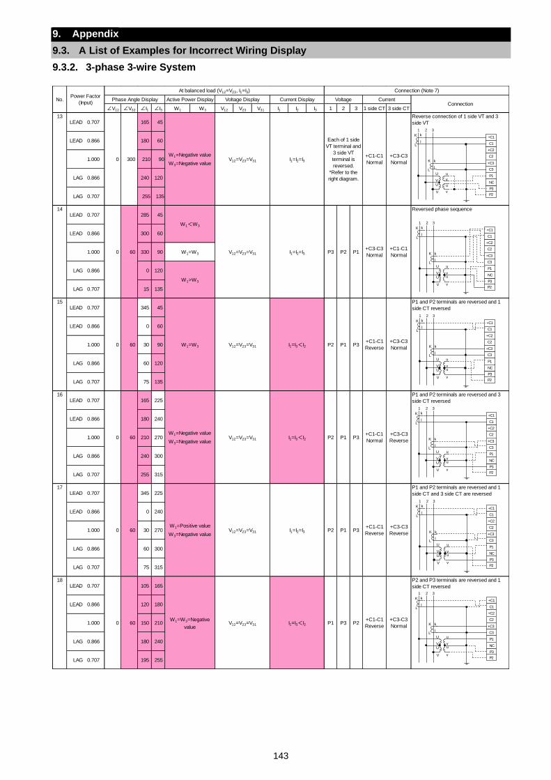
143
9. Appendix
9.3. A List of Examples for Incorrect Wiring Display
9.3.2. 3-phase 3-wire System
∠V12 ∠V32 ∠I1 ∠I3 W1 W3 V12 V23 V31 I1 I2 I3 1 2 3 1 side CT 3 side CT
13LEAD 0.707 165 45
Reverse connection of 1 side VT and 3
side VT
LEAD 0.866 180 60
1.000 210 90
LAG 0.866 240 120
LAG 0.707 255 135
14LEAD 0.707 285 45
Reversed phase sequence
LEAD 0.866 300 60
1.000 330 90
LAG 0.866 0 120
LAG 0.707 15 135
15LEAD 0.707 345 45
P1 and P2 terminals are reversed and 1
side CT reversed
LEAD 0.866 0 60
1.000 30 90
LAG 0.866 60 120
LAG 0.707 75 135
16LEAD 0.707 165 225
P1 and P2 terminals are reversed and 3
side CT reversed
LEAD 0.866 180 240
1.000 210 270
LAG 0.866 240 300
LAG 0.707 255 315
17LEAD 0.707 345 225
P1 and P2 terminals are reversed and 1
side CT and 3 side CT are reversed
LEAD 0.866 0 240
1.000 30 270
LAG 0.866 60 300
LAG 0.707 75 315
18LEAD 0.707 105 165
P2 and P3 terminals are reversed and 1
side CT reversed
LEAD 0.866 120 180
1.000 150 210
LAG 0.866 180 240
LAG 0.707 195 255
No.Power Factor
(Input)
At balanced load (V12=V23, I1=I3) Connection (Note 7)
Phase Angle Display Active Power Display Voltage Display Current Display Voltage CurrentConnection
0 300W1=Negative value
W3=Negative valueV12=V23=V31 I1=I2=I3
Each of 1 side
VT terminal and
3 side VT
terminal is
reversed.
*Refer to the
right diagram.
+C1-C1
Normal
+C3-C3
Normal
P2 P1+C3-C3
Normal
+C1-C1
NormalW1=W3
W1>W3
0 60
W1<W3
V12=V23=V31 I1=I2=I3 P3
P1 P3+C1-C1
Reverse
+C3-C3
Normal
0 60W1=Negative value
W3=Negative valueV12=V23=V31 I1=I3<I2 P2
0 60 W1=W3 V12=V23=V31 I1=I3<I2 P2
P1 P3+C1-C1
Normal
+C3-C3
Reverse
0 60W1=Positive value
W3=Negative valueV12=V23=V31 I1=I2=I3 P2 P1 P3
+C1-C1
Reverse
+C3-C3
Reverse
0 60W1=W3=Negative
valueV12=V23=V31 I1=I3<I2 P1 P3 P2
+C1-C1
Reverse
+C3-C3
Normal
+C2
C2
+C3
C3
P1
P3
NC
+C1
C1
P2
K
L
k
l
K
L
k
l
U u
V vU u
V v
1 2 3
+C2
C2
+C3
C3
P1
P3
NC
+C1
C1
P2
K
L
k
l
K
L
k
l
U u
V vU u
V v
1 2 3
+C2
C2
+C3
C3
P1
P3
NC
+C1
C1
P2
K
L
k
l
K
L
k
l
U u
V vU u
V v
1 2 3
+C2
C2
+C3
C3
P1
P3
NC
+C1
C1
P2
K
L
k
l
K
L
k
l
U u
V vU u
V v
1 2 3
+C2
C2
+C3
C3
P1
P3
NC
+C1
C1
P2
K
L
k
l
K
L
k
l
U u
V vU u
V v
1 2 3
+C2
C2
+C3
C3
P1
P3
NC
+C1
C1
P2
K
L
k
l
K
L
k
l
U u
V v
U u
V v
1 2 3
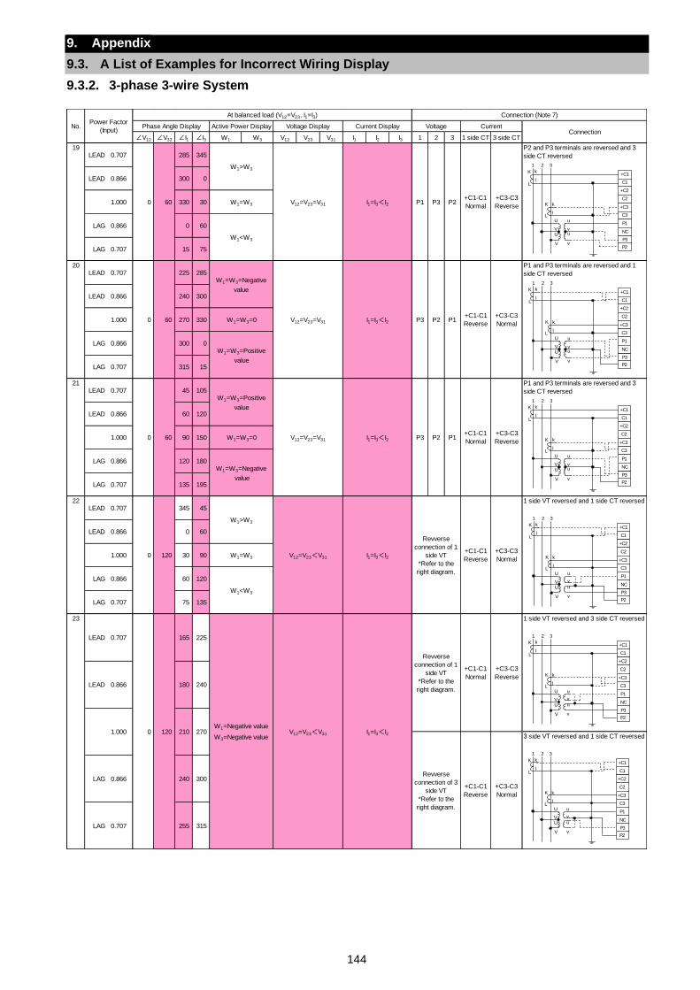
144
9. Appendix
9.3. A List of Examples for Incorrect Wiring Display
9.3.2. 3-phase 3-wire System
∠V12 ∠V32 ∠I1 ∠I3 W1 W3 V12 V23 V31 I1 I2 I3 1 2 3 1 side CT 3 side CT
19LEAD 0.707 285 345
P2 and P3 terminals are reversed and 3
side CT reversed
LEAD 0.866 300 0
1.000 330 30
LAG 0.866 0 60
LAG 0.707 15 75
20LEAD 0.707 225 285
P1 and P3 terminals are reversed and 1
side CT reversed
LEAD 0.866 240 300
1.000 270 330
LAG 0.866 300 0
LAG 0.707 315 15
21LEAD 0.707 45 105
P1 and P3 terminals are reversed and 3
side CT reversed
LEAD 0.866 60 120
1.000 90 150
LAG 0.866 120 180
LAG 0.707 135 195
22LEAD 0.707 345 45
1 side VT reversed and 1 side CT reversed
LEAD 0.866 0 60
1.000 30 90
LAG 0.866 60 120
LAG 0.707 75 135
23 1 side VT reversed and 3 side CT reversed
3 side VT reversed and 1 side CT reversed
No.Power Factor
(Input)
At balanced load (V12=V23, I1=I3) Connection (Note 7)
Phase Angle Display Active Power DisplayConnection
0 60
W1>W3
V12=V23=V31 I1=I3<I2 P1 P3 P2+C1-C1
Normal
+C3-C3
ReverseW1=W3
W1<W3
Voltage Display Current Display Voltage Current
P2 P1+C1-C1
Reverse
+C3-C3
NormalW1=W3=0
W1=W3=Positive
value
0 60
W1=W3=Negative
value
V12=V23=V31 I1=I3<I2 P3
P2 P1+C1-C1
Normal
+C3-C3
ReverseW1=W3=0
W1=W3=Negative
value
0 60
W1=W3=Positive
value
V12=V23=V31 I1=I3<I2 P3
+C1-C1
Reverse
+C3-C3
NormalW1=W3
W1<W3
LEAD 0.707
0 120
165 225
0 120
W1>W3
V12=V23<V31 I1=I3<I2
Revverse
connection of 1
side VT
*Refer to the
right diagram.
W1=Negative value
W3=Negative valueV12=V23<V31 I1=I3<I2
Revverse
connection of 1
side VT
*Refer to the
right diagram.
+C1-C1
Normal
+C3-C3
Reverse
Revverse
connection of 3
side VT
*Refer to the
right diagram.
+C1-C1
Reverse
+C3-C3
Normal
LAG 0.866 240 300
LAG 0.707 255 315
LEAD 0.866 180 240
1.000 210 270
+C2
C2
+C3
C3
P1
P3
NC
+C1
C1
P2
K
L
k
l
K
L
k
l
U u
V vU u
V v
1 2 3
+C2
C2
+C3
C3
P1
P3
NC
+C1
C1
P2
K
L
k
l
K
L
k
l
U u
V vU u
V v
1 2 3
+C2
C2
+C3
C3
P1
P3
NC
+C1
C1
P2
K
L
k
l
K
L
k
l
U u
V vU u
V v
1 2 3
+C2
C2
+C3
C3
P1
P3
NC
+C1
C1
P2
K
L
k
l
K
L
k
l
U u
V v
U u
V v
1 2 3
+C2
C2
+C3
C3
P1
P3
NC
+C1
C1
P2
K
L
k
l
K
L
k
l
U u
V v
U u
V v
1 2 3
+C2
C2
+C3
C3
P1
P3
NC
+C1
C1
P2
K
L
k
l
K
L
k
l
U u
V v
U u
V v
1 2 3
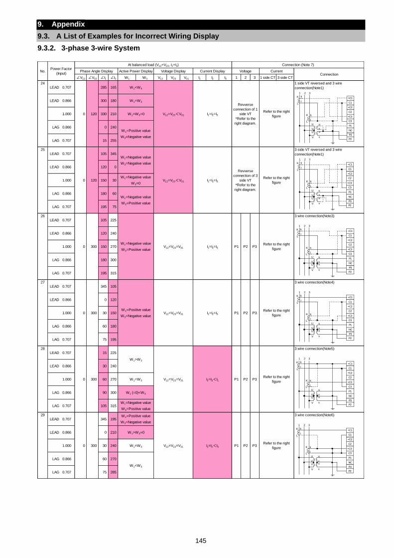
145
9. Appendix
9.3. A List of Examples for Incorrect Wiring Display
9.3.2. 3-phase 3-wire System
∠V12 ∠V32 ∠I1 ∠I3 W1 W3 V12 V23 V31 I1 I2 I3 1 2 3 1 side CT 3 side CT
24LEAD 0.707 285 165
1 side VT reversed and 3 wire
connection(Note1)
LEAD 0.866 300 180
1.000 330 210
LAG 0.866 0 240
LAG 0.707 15 255
25LEAD 0.707 105 345
3 side VT reversed and 3 wire
connection(Note1)
LEAD 0.866 120 0
1.000 150 30
LAG 0.866 180 60
LAG 0.707 195 75
26LEAD 0.707 105 225
3 wire connection(Note3)
LEAD 0.866 120 240
1.000 150 270
LAG 0.866 180 300
LAG 0.707 195 315
27LEAD 0.707 345 105
3 wire connection(Note4)
LEAD 0.866 0 120
1.000 30 150
LAG 0.866 60 180
LAG 0.707 75 195
28LEAD 0.707 15 225
3 wire connection(Note5)
LEAD 0.866 30 240
1.000 60 270
LAG 0.866 90 300
LAG 0.707 105 315
29LEAD 0.707 345 195
3 wire connection(Note6)
LEAD 0.866 0 210
1.000 30 240
LAG 0.866 60 270
LAG 0.707 75 285
No.Power Factor
(Input)
At balanced load (V12=V23, I1=I3)
Revverse
connection of 1
side VT
*Refer to the
right diagram.
Refer to the right
figure
W1=W3
W1>W3=0
Revverse
connection of 3
side VT
*Refer to the
right diagram.
P3Refer to the right
figure
0 300
W1>W3
Connection (Note 7)
Phase Angle Display Active Power Display Voltage Display Current Display Voltage Current
W1=Positive value
W3=Negative value
0 120
W1=Negative value
W3=Negative value
V12=V23<V31 I1=I2=I3
Connection
0 120
W1<W3
V12=V23<V31 I1=I2=I3
Refer to the right
figure
W1=Negative value
W3=0
W1=Negative value
W3=Positive value
0 300W1=Negative value
W3=Positive valueV12=V23=V31 I1=I2=I3 P1 P2 P3
Refer to the right
figure
0 300W1=Positive value
W3=Negative valueV12=V23=V31 I1=I2=I3 P1 P2
0 300
W1=Positive value
W3=Negative value
V12=V23=V31 I1=I2<I3 P1 P2 P3Refer to the right
figure
W1>W3=0
W1=W3
W1<W3
Refer to the right
figureW1=W3
W1 (=0)<W3
W1=Negative value
W3=Positive value
V12=V23=V31 I2=I3<I1 P1 P2 P3
+C2
C2
+C3
C3
P1
P3
NC
+C1
C1
P2
K
L
k
l
K
L
k
l
U u
V v
U u
V v
1 2 3
+C2
C2
+C3
C3
P1
P3
NC
+C1
C1
P2
K
L
k
l
K
L
k
l
U u
V v
U u
V v
1 2 3
+C2
C2
+C3
C3
P1
P3
NC
+C1
C1
P2
K
L
k
l
K
L
k
l
U u
V vU u
V v
1 2 3
+C2
C2
+C3
C3
P1
P3
NC
+C1
C1
P2
K
L
k
l
K
L
k
l
U u
V vU u
V v
1 2 3
+C2
C2
+C3
C3
P1
P3
NC
+C1
C1
P2
K
L
k
l
K
L
k
l
U u
V vU u
V v
1 2 3
+C2
C2
+C3
C3
P1
P3
NC
+C1
C1
P2
K
L
k
l
K
L
k
l
U u
V vU u
V v
1 2 3
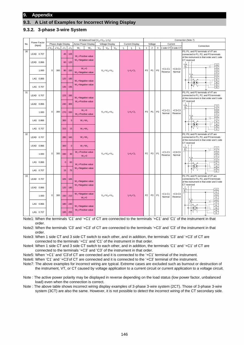
146
9. Appendix
9.3. A List of Examples for Incorrect Wiring Display
9.3.2. 3-phase 3-wire System
Note1: When the terminals ‘C1’ and ‘+C1’ of CT are connected to the terminals ‘+C1’ and ‘C1’ of the instrument in that
order.
Note2: When the terminals ‘C3’ and ‘+C3’ of CT are connected to the terminals ‘+C3’ and ‘C3’ of the instrument in that
order.
Note3: When 1 side CT and 3 side CT switch to each other, and in addition, the terminals ‘C3’ and ‘+C3’ of CT are
connected to the terminals ‘+C1’ and ‘C1’ of the instrument in that order.
Note4: When 1 side CT and 3 side CT switch to each other, and in addition, the terminals ‘C1’ and ‘+C1’ of CT are
connected to the terminals ‘+C3’ and ‘C3’ of the instrument in that order.
Note5: When ‘+C1’ and ‘C3’of CT are connected and it is connected to the ‘+C1’ terminal of the instrument.
Note6: When ‘C1’ and ‘+C3’of CT are connected and it is connected to the ‘+C3’ terminal of the instrument.
Note7: The above examples for incorrect wiring are typical. Extreme cases are excluded such as burnout or destruction of
the instrument, VT, or CT caused by voltage application to a current circuit or current application to a voltage circuit.
Note : The active power polarity may be displayed in reverse depending on the load status (low power factor, unbalanced
load) even when the connection is correct.
Note : The above table shows incorrect wiring display examples of 3-phase 3-wire system (2CT). Those of 3-phase 3-wire
system (3CT) are also the same. However, it is not possible to detect the incorrect wiring of the CT secondary side.
∠V12 ∠V32 ∠I1 ∠I3 W1 W3 V12 V23 V31 I1 I2 I3 1 2 3 1 side CT 3 side CT
30LEAD 0.707 45 105
LEAD 0.866 60 120
1.000 90 150
LAG 0.866 120 180
LAG 0.707 135 195
31
LEAD 0.707 225 285
LEAD 0.866 240 300
1.000 270 330
LAG 0.866 300 0
LAG 0.707 315 15
32
LEAD 0.707 285 345
LEAD 0.866 300 0
1.000 330 30
LAG 0.866 0 60
LAG 0.707 15 75
33
LEAD 0.707 105 165
LEAD 0.866 120 180
1.000 150 210
LAG 0.866 180 240
LAG 0.707 195 255
P3, P1, and P2 terminals of VT are
connected to P1, P2, and P3 terminals
of the instrument in that order and 1 side
CT reversed
P3, P1, and P2 terminals of VT are
connected to P1, P2, and P3 terminals
of the instrument in that order and 3 side
CT reversed
P2, P3, and P1 terminals of VT are
connected to P1, P2, and P3 terminals
of the instrument in that order and 1 side
CT reversed
P2, P3, and P1 terminals of VT are
connected to P1, P2, and P3 terminals
of the instrument in that order and 3 side
CT reversed
No.Power Factor
(Input)
At balanced load (V12=V23, I1=I3) Connection (Note 7)
Phase Angle Display Active Power Display Voltage Display Current Display Voltage Current
0 300
W1=Negative value
W3=Positive value
V12=V23=V31 I1=I3<I2 P3 P1
Connection
0 300
W1=Positive value
W3=Negative value
V12=V23=V31 I1=I3<I2 P3 P1 P2+C1-C1
Reverse
P2+C1-C1
Normal
+C3-C3
Reverse
W1=0
W3=Positive value
W1=W3
W1>W3
+C3-C3
Normal
W1=0
W3=Negative value
W1=Negative value
W3=Negative value
P3 P1+C1-C1
Reverse
+C3-C3
Normal
W1=W3
W1=Positive value
W3=0
W1=Positive value
W3=Negative value
0 300
W1<W3
V12=V23=V31 I1=I3<I2 P2
P3 P1+C1-C1
Normal
+C3-C3
Reverse
W1=Negative value
W3=0
W1=Negative value
W3=Positive value
0 300
W1=Negative value
W3=Negative value
V12=V23=V31 I1=I3<I2 P2
+C2
C2
+C3
C3
P1
P3
NC
+C1
C1
P2
K
L
k
l
K
L
k
l
U u
V vU u
V v
1 2 3
+C2
C2
+C3
C3
P1
P3
NC
+C1
C1
P2
K
L
k
l
K
L
k
l
U u
V vU u
V v
1 2 3
+C2
C2
+C3
C3
P1
P3
NC
+C1
C1
P2
K
L
k
l
K
L
k
l
U u
V vU u
V v
1 2 3
+C2
C2
+C3
C3
P1
P3
NC
+C1
C1
P2
K
L
k
l
K
L
k
l
U u
V vU u
V v
1 2 3
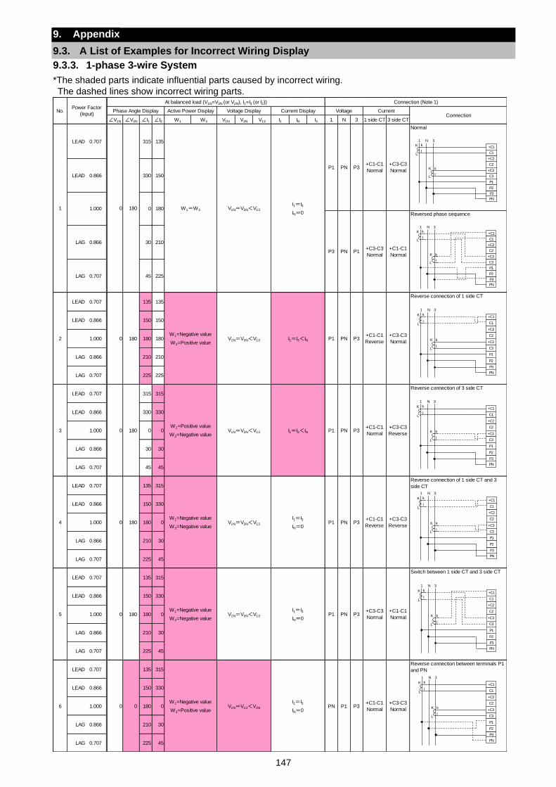
147
9. Appendix
9.3. A List of Examples for Incorrect Wiring Display
9.3.3. 1-phase 3-wire System
*The shaded parts indicate influential parts caused by incorrect wiring.
The dashed lines show incorrect wiring parts.
∠V1N ∠V3N ∠I1 ∠I3 W1 W3 V1N V3N V13 I1 IN I3 1 N 3 1 side CT 3 side CT
Normal
Reversed phase sequence
LEAD 0.707 135 135Reverse connection of 1 side CT
LEAD 0.866 150 150
1.000 180 180
LAG 0.866 210 210
LAG 0.707 225 225
LEAD 0.707 315 315Reverse connection of 3 side CT
LEAD 0.866 330 330
1.000 0 0
LAG 0.866 30 30
LAG 0.707 45 45
LEAD 0.707 135 315Reverse connection of 1 side CT and 3
side CT
LEAD 0.866 150 330
1.000 180 0
LAG 0.866 210 30
LAG 0.707 225 45
LEAD 0.707 135 315Switch between 1 side CT and 3 side CT
LEAD 0.866 150 330
1.000 180 0
LAG 0.866 210 30
LAG 0.707 225 45
LEAD 0.707 135 315Reverse connection between terminals P1
and PN
LEAD 0.866 150 330
1.000 180 0
LAG 0.866 210 30
LAG 0.707 225 45
Connection
1
LEAD 0.707
0 180
315 135
W1=W3 V1N=V3N<V13
No.Power Factor
(Input)
At balanced load (V1N=V3N (or V2N), I1=I3 (or I2)) Connection (Note 1)
Phase Angle Display Active Power Display Voltage Display Current Display Voltage Current
P1 PN P3+C1-C1
Normal
+C3-C3
Normal
P3 PN P1+C3-C3
Normal
LEAD 0.866 330 150
1.000 0 180I1=I3
IN=0
+C1-C1
Normal
LAG 0.866 30 210
LAG 0.707 45 225
3 0 180W1=Positive value
W3=Negative valueV1N=V3N<V13
2 0 180W1=Negative value
W3=Positive valueV1N=V3N<V13
I1=I3<IN P1 PN P3+C1-C1
Normal
+C3-C3
Reverse
P1 PN P3+C1-C1
Reverse
+C3-C3
NormalI1=I3<IN
5 0 180W1=Negative value
W3=Negative valueV1N=V3N<V13
4 0 180W1=Negative value
W3=Negative valueV1N=V3N<V13
I1=I3
IN=0P1 PN P3
+C3-C3
Normal
+C1-C1
Normal
P1 PN P3+C1-C1
Reverse
+C3-C3
Reverse
I1=I3
IN=0
6 0 0W1=Negative value
W3=Positive valueV1N=V13<V3N
I1=I3
IN=0PN P1 P3
+C1-C1
Normal
+C3-C3
Normal
+C2
C2
+C3
C3
P1
P3
P2
+C1
C1
PN
K
L
k
l
K
L
k
l
1 N 3
+C2
C2
+C3
C3
P1
P3
P2
+C1
C1
PN
K
L
k
l
K
L
k
l
1 N 3
+C2
C2
+C3
C3
P1
P3
P2
+C1
C1
PN
K
L
k
l
K
L
k
l
1 N 3
+C2
C2
+C3
C3
P1
P3
P2
+C1
C1
PN
K
L
k
l
K
L
k
l
1 N 3
+C2
C2
+C3
C3
P1
P3
P2
+C1
C1
PN
K
L
k
l
K
L
k
l
1 N 3
+C2
C2
+C3
C3
P1
P3
P2
+C1
C1
PN
K
L
k
l
K
L
k
l
1 N 3
+C2
C2
+C3
C3
P1
P3
P2
+C1
C1
PN
K
L
k
l
K
L
k
l
1 N 3
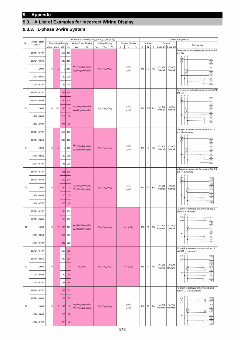
148
9. Appendix
9.3. A List of Examples for Incorrect Wiring Display
9.3.3. 1-phase 3-wire System
∠V1N ∠V3N ∠I1 ∠I3 W1 W3 V1N V3N V13 I1 IN I3 1 N 3 1 side CT 3 side CT
LEAD 0.707 315 135Reverse connection between terminals P3
and PN
LEAD 0.866 330 150
1.000 0 180
LAG 0.866 30 210
LAG 0.707 45 225
LEAD 0.707 135 315Reverse connection between terminals P1
and P3
LEAD 0.866 150 330
1.000 180 0
LAG 0.866 210 30
LAG 0.707 225 45
LEAD 0.707 315 135Voltage are connected the order of P3, P1,
and PN terminals
LEAD 0.866 330 150
1.000 0 180
LAG 0.866 30 210
LAG 0.707 45 225
LEAD 0.707 135 315Voltage are connected the order of PN, P3,
and P1 terminals
LEAD 0.866 150 330
1.000 180 0
LAG 0.866 210 30
LAG 0.707 225 45
LEAD 0.707 135 135P3 and PN terminals are reversed and 1
side CT is reversed.
LEAD 0.866 150 150
1.000 180 180
LAG 0.866 210 210
LAG 0.707 225 225
LEAD 0.707 315 315P3 and PN terminals are reversed and 3
side CT is reversed.
LEAD 0.866 330 330
1.000 0 0
LAG 0.866 30 30
LAG 0.707 45 45
LEAD 0.707 135 315P3 and PN terminals are reversed, and
both of CTs are reversed.
LEAD 0.866 150 330
1.000 180 0
LAG 0.866 210 30
LAG 0.707 225 45
No.Power Factor
(Input)
At balanced load (V1N=V3N (or V2N), I1=I3 (or I2)) Connection (Note 1)
Phase Angle Display Active Power Display Voltage Display Current Display Voltage CurrentConnection
8 0 180W1=Negative value
W3=Negative valueV1N=V3N<V13
7 0 0W1=Positive value
W3=Negative valueV1N>V3N=V13
I1=I3
IN=0P3 PN P1
+C1-C1
Normal
+C3-C3
Normal
P1 P3 PN+C1-C1
Normal
+C3-C3
Normal
I1=I3
IN=0
10 0 0W1=Negative value
W3=Positive valueV1N>V3N=V13
9 0 0W1=Positive value
W3=Negative valueV1N=V13<V3N
I1=I3
IN=0PN P3 P1
+C1-C1
Normal
+C3-C3
Normal
P3 P1 PN+C1-C1
Normal
+C3-C3
Normal
I1=I3
IN=0
12 0 0 W1>W3 V1N>V3N=V13
11 0 0W1=Negative value
W3=Negative valueV1N>V3N=V13
I1=I3<IN P1 P3 PN+C1-C1
Normal
+C3-C3
Reverse
P1 P3 PN+C1-C1
Reverse
+C3-C3
NormalI1=I3<IN
13 0 0W1=Negative value
W3=Positive valueV1N>V3N=V13
I1=I3
IN=0P1 P3 PN
+C1-C1
Reverse
+C3-C3
Reverse
+C2
C2
+C3
C3
P1
P3
P2
+C1
C1
PN
K
L
k
l
K
L
k
l
1 N 3
+C2
C2
+C3
C3
P1
P3
P2
+C1
C1
PN
K
L
k
l
K
L
k
l
1 N 3
+C2
C2
+C3
C3
P1
P3
P2
+C1
C1
PN
K
L
k
l
K
L
k
l
1 N 3
+C2
C2
+C3
C3
P1
P3
P2
+C1
C1
PN
K
L
k
l
K
L
k
l
1 N 3
+C2
C2
+C3
C3
P1
P3
P2
+C1
C1
PN
K
L
k
l
K
L
k
l
1 N 3
+C2
C2
+C3
C3
P1
P3
P2
+C1
C1
PN
K
L
k
l
K
L
k
l
1 N 3
+C2
C2
+C3
C3
P1
P3
P2
+C1
C1
PN
K
L
k
l
K
L
k
l
1 N 3
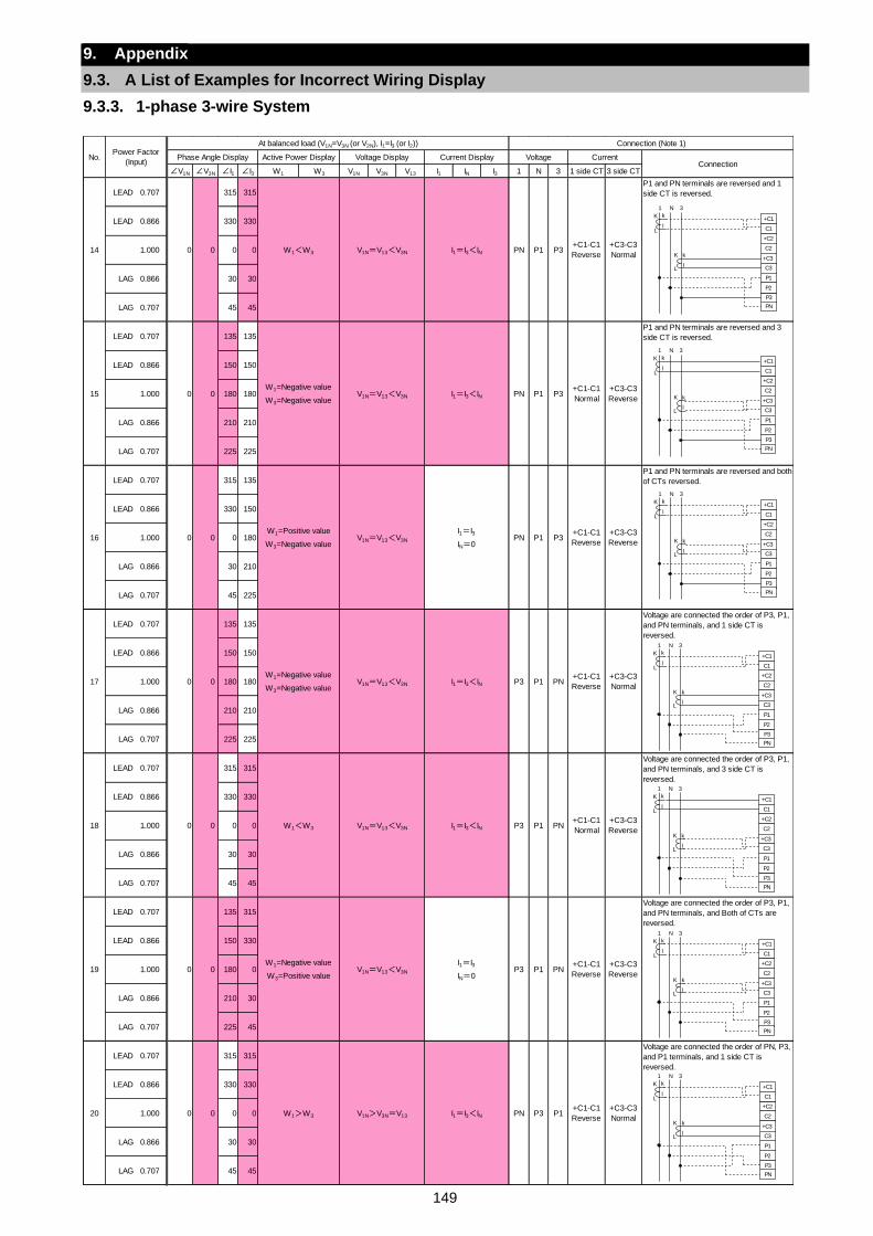
149
9. Appendix
9.3. A List of Examples for Incorrect Wiring Display
9.3.3. 1-phase 3-wire System
∠V1N ∠V3N ∠I1 ∠I3 W1 W3 V1N V3N V13 I1 IN I3 1 N 3 1 side CT 3 side CT
LEAD 0.707 315 315P1 and PN terminals are reversed and 1
side CT is reversed.
LEAD 0.866 330 330
1.000 0 0
LAG 0.866 30 30
LAG 0.707 45 45
LEAD 0.707 135 135P1 and PN terminals are reversed and 3
side CT is reversed.
LEAD 0.866 150 150
1.000 180 180
LAG 0.866 210 210
LAG 0.707 225 225
LEAD 0.707 315 135P1 and PN terminals are reversed and both
of CTs reversed.
LEAD 0.866 330 150
1.000 0 180
LAG 0.866 30 210
LAG 0.707 45 225
LEAD 0.707 135 135
LEAD 0.866 150 150
1.000 180 180
LAG 0.866 210 210
LAG 0.707 225 225
LEAD 0.707 315 315Voltage are connected the order of P3, P1,
and PN terminals, and 3 side CT is
reversed.
LEAD 0.866 330 330
1.000 0 0
LAG 0.866 30 30
LAG 0.707 45 45
LEAD 0.707 135 315
LEAD 0.866 150 330
1.000 180 0
LAG 0.866 210 30
LAG 0.707 225 45
LEAD 0.707 315 315
LEAD 0.866 330 330
1.000 0 0
LAG 0.866 30 30
LAG 0.707 45 45
Voltage are connected the order of PN, P3,
and P1 terminals, and 1 side CT is
reversed.
Voltage are connected the order of P3, P1,
and PN terminals, and Both of CTs are
reversed.
Voltage are connected the order of P3, P1,
and PN terminals, and 1 side CT is
reversed.
No.Power Factor
(Input)
At balanced load (V1N=V3N (or V2N), I1=I3 (or I2)) Connection (Note 1)
Phase Angle Display Active Power Display Voltage Display Current Display Voltage CurrentConnection
15 0 0W1=Negative value
W3=Negative valueV1N=V13<V3N
14 0 0 W1<W3 V1N=V13<V3N
I1=I3<IN PN P1 P3+C1-C1
Normal
+C3-C3
Reverse
PN P1 P3+C1-C1
Reverse
+C3-C3
NormalI1=I3<IN
17 0 0W1=Negative value
W3=Negative valueV1N=V13<V3N
16 0 0W1=Positive value
W3=Negative valueV1N=V13<V3N
I1=I3<IN P3 P1 PN+C1-C1
Reverse
+C3-C3
Normal
PN P1 P3+C1-C1
Reverse
+C3-C3
Reverse
I1=I3
IN=0
19 0 0W1=Negative value
W3=Positive valueV1N=V13<V3N
18 0 0 W1<W3 V1N=V13<V3N
I1=I3
IN=0P3 P1 PN
+C1-C1
Reverse
+C3-C3
Reverse
P3 P1 PN+C1-C1
Normal
+C3-C3
ReverseI1=I3<IN
20 0 0 W1>W3 V1N>V3N=V13 I1=I3<IN PN P3 P1+C1-C1
Reverse
+C3-C3
Normal
+C2
C2
+C3
C3
P1
P3
P2
+C1
C1
PN
K
L
k
l
K
L
k
l
1 N 3
+C2
C2
+C3
C3
P1
P3
P2
+C1
C1
PN
K
L
k
l
K
L
k
l
1 N 3
+C2
C2
+C3
C3
P1
P3
P2
+C1
C1
PN
K
L
k
l
K
L
k
l
1 N 3
+C2
C2
+C3
C3
P1
P3
P2
+C1
C1
PN
K
L
k
l
K
L
k
l
1 N 3
+C2
C2
+C3
C3
P1
P3
P2
+C1
C1
PN
K
L
k
l
K
L
k
l
1 N 3
+C2
C2
+C3
C3
P1
P3
P2
+C1
C1
PN
K
L
k
l
K
L
k
l
1 N 3
+C2
C2
+C3
C3
P1
P3
P2
+C1
C1
PN
K
L
k
l
K
L
k
l
1 N 3
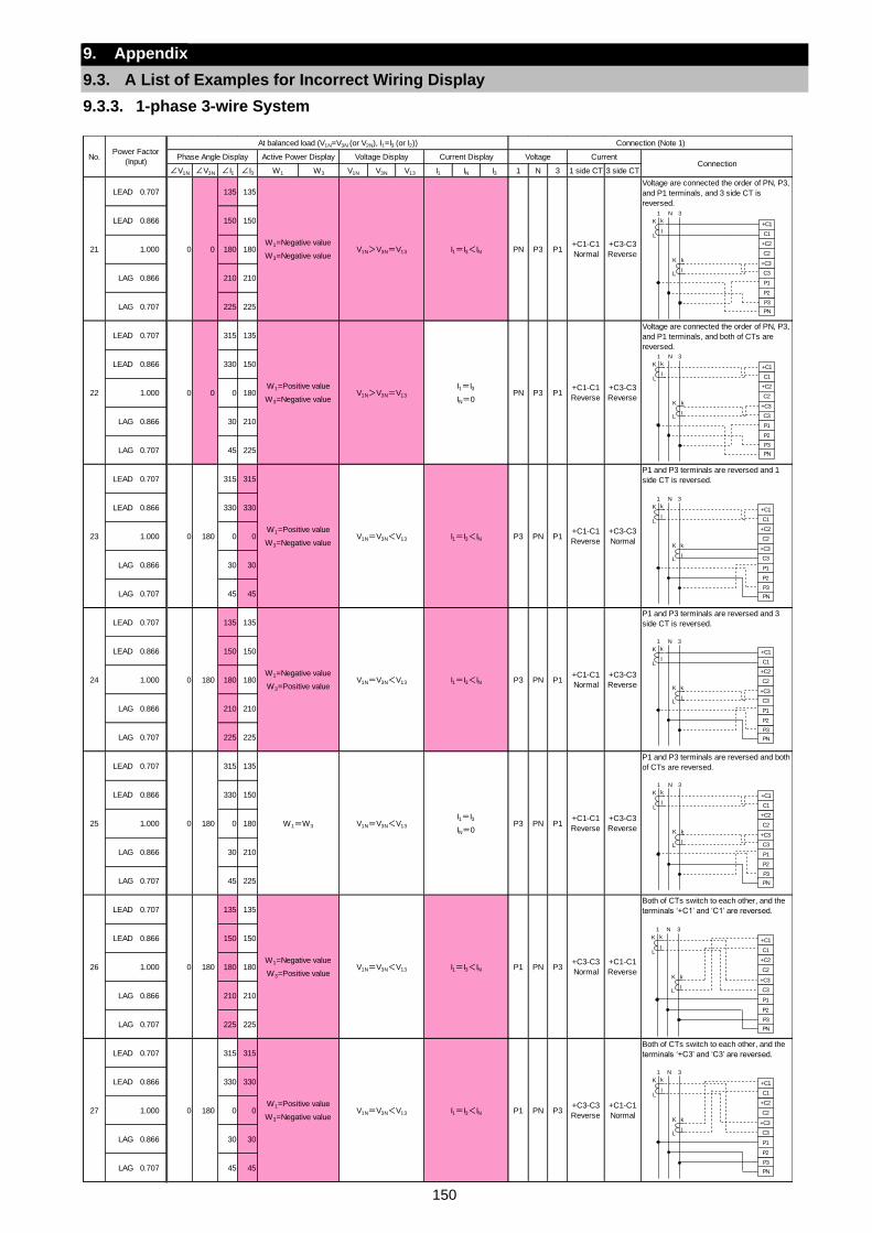
150
9. Appendix
9.3. A List of Examples for Incorrect Wiring Display
9.3.3. 1-phase 3-wire System
∠V1N ∠V3N ∠I1 ∠I3 W1 W3 V1N V3N V13 I1 IN I3 1 N 3 1 side CT 3 side CT
LEAD 0.707 135 135
LEAD 0.866 150 150
1.000 180 180
LAG 0.866 210 210
LAG 0.707 225 225
LEAD 0.707 315 135
LEAD 0.866 330 150
1.000 0 180
LAG 0.866 30 210
LAG 0.707 45 225
LEAD 0.707 315 315P1 and P3 terminals are reversed and 1
side CT is reversed.
LEAD 0.866 330 330
1.000 0 0
LAG 0.866 30 30
LAG 0.707 45 45
LEAD 0.707 135 135P1 and P3 terminals are reversed and 3
side CT is reversed.
LEAD 0.866 150 150
1.000 180 180
LAG 0.866 210 210
LAG 0.707 225 225
LEAD 0.707 315 135P1 and P3 terminals are reversed and both
of CTs are reversed.
LEAD 0.866 330 150
1.000 0 180
LAG 0.866 30 210
LAG 0.707 45 225
LEAD 0.707 135 135Both of CTs switch to each other, and the
terminals ‘+C1’ and ‘C1’ are reversed.
LEAD 0.866 150 150
1.000 180 180
LAG 0.866 210 210
LAG 0.707 225 225
LEAD 0.707 315 315Both of CTs switch to each other, and the
terminals ‘+C3’ and ‘C3’ are reversed.
LEAD 0.866 330 330
1.000 0 0
LAG 0.866 30 30
LAG 0.707 45 45
Voltage are connected the order of PN, P3,
and P1 terminals, and both of CTs are
reversed.
Voltage are connected the order of PN, P3,
and P1 terminals, and 3 side CT is
reversed.
No.Power Factor
(Input)
At balanced load (V1N=V3N (or V2N), I1=I3 (or I2)) Connection (Note 1)
Phase Angle Display Active Power Display Voltage Display Current Display Voltage CurrentConnection
22 0 0W1=Positive value
W3=Negative valueV1N>V3N=V13
21 0 0W1=Negative value
W3=Negative valueV1N>V3N=V13
I1=I3
IN=0PN P3 P1
+C1-C1
Reverse
+C3-C3
Reverse
PN P3 P1+C1-C1
Normal
+C3-C3
ReverseI1=I3<IN
24 0 180W1=Negative value
W3=Positive valueV1N=V3N<V13
23 0 180W1=Positive value
W3=Negative valueV1N=V3N<V13
I1=I3<IN P3 PN P1+C1-C1
Normal
+C3-C3
Reverse
P3 PN P1+C1-C1
Reverse
+C3-C3
NormalI1=I3<IN
26 0 180W1=Negative value
W3=Positive valueV1N=V3N<V13
25 0 180 W1=W3 V1N=V3N<V13
I1=I3<IN P1 PN P3+C3-C3
Normal
+C1-C1
Reverse
P3 PN P1+C1-C1
Reverse
+C3-C3
Reverse
I1=I3
IN=0
27 0 180W1=Positive value
W3=Negative valueV1N=V3N<V13 I1=I3<IN P1 PN P3
+C3-C3
Reverse
+C1-C1
Normal
+C2
C2
+C3
C3
P1
P3
P2
+C1
C1
PN
K
L
k
l
K
L
k
l
1 N 3
+C2
C2
+C3
C3
P1
P3
P2
+C1
C1
PN
K
L
k
l
K
L
k
l
1 N 3
+C2
C2
+C3
C3
P1
P3
P2
+C1
C1
PN
K
L
k
l
K
L
k
l
1 N 3
+C2
C2
+C3
C3
P1
P3
P2
+C1
C1
PN
K
L
k
l
K
L
k
l
1 N 3
+C2
C2
+C3
C3
P1
P3
P2
+C1
C1
PN
K
L
k
l
K
L
k
l
1 N 3
+C2
C2
+C3
C3
P1
P3
P2
+C1
C1
PN
K
L
k
l
K
L
k
l
1 N 3
+C2
C2
+C3
C3
P1
P3
P2
+C1
C1
PN
K
L
k
l
K
L
k
l
1 N 3
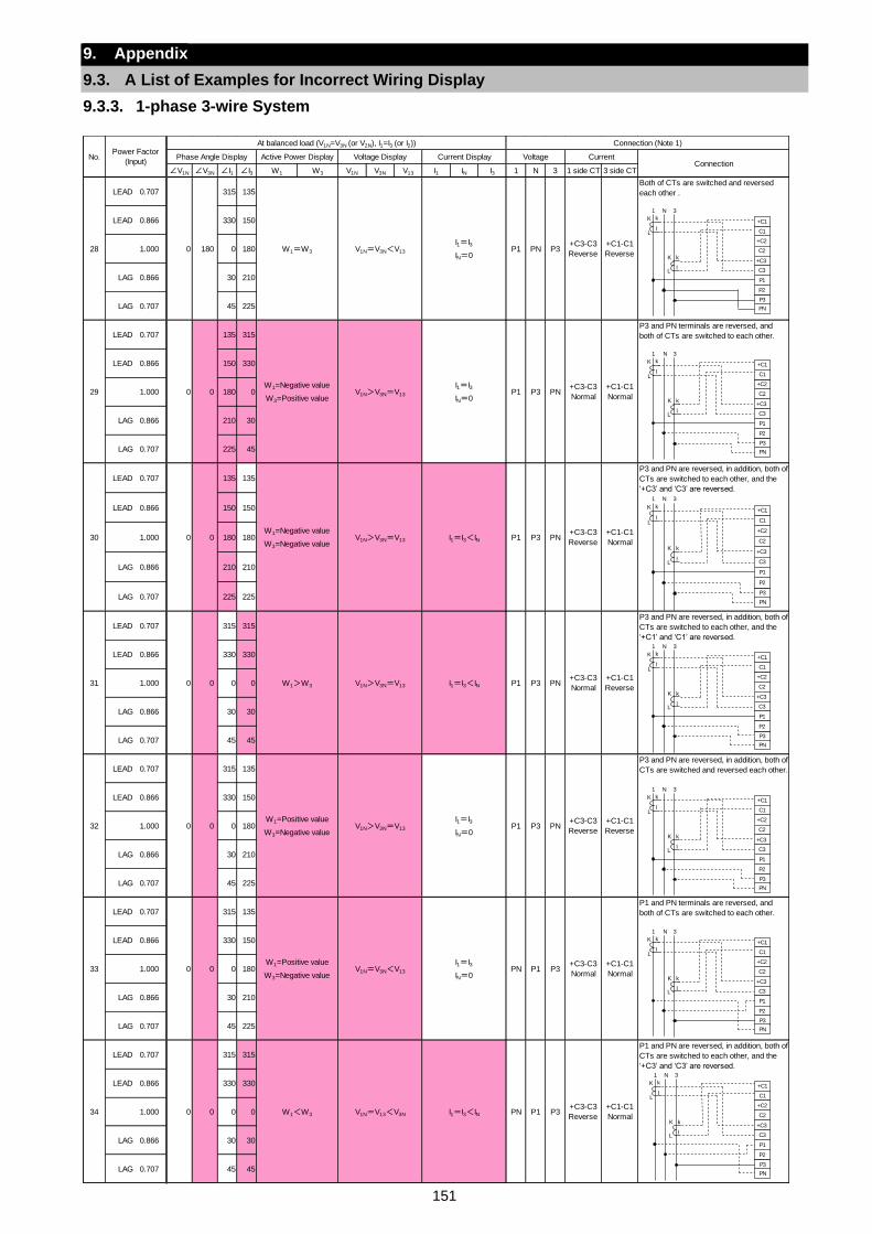
151
9. Appendix
9.3. A List of Examples for Incorrect Wiring Display
9.3.3. 1-phase 3-wire System
∠V1N ∠V3N ∠I1 ∠I3 W1 W3 V1N V3N V13 I1 IN I3 1 N 3 1 side CT 3 side CT
LEAD 0.707 315 135Both of CTs are switched and reversed
each other .
LEAD 0.866 330 150
1.000 0 180
LAG 0.866 30 210
LAG 0.707 45 225
LEAD 0.707 135 315P3 and PN terminals are reversed, and
both of CTs are switched to each other.
LEAD 0.866 150 330
1.000 180 0
LAG 0.866 210 30
LAG 0.707 225 45
LEAD 0.707 135 135
LEAD 0.866 150 150
1.000 180 180
LAG 0.866 210 210
LAG 0.707 225 225
LEAD 0.707 315 315
LEAD 0.866 330 330
1.000 0 0
LAG 0.866 30 30
LAG 0.707 45 45
LEAD 0.707 315 135
LEAD 0.866 330 150
1.000 0 180
LAG 0.866 30 210
LAG 0.707 45 225
LEAD 0.707 315 135P1 and PN terminals are reversed, and
both of CTs are switched to each other.
LEAD 0.866 330 150
1.000 0 180
LAG 0.866 30 210
LAG 0.707 45 225
LEAD 0.707 315 315
LEAD 0.866 330 330
1.000 0 0
LAG 0.866 30 30
LAG 0.707 45 45
No.Power Factor
(Input)
At balanced load (V1N=V3N (or V2N), I1=I3 (or I2)) Connection (Note 1)
Phase Angle Display Active Power Display Voltage Display Current Display Voltage CurrentConnection
29 0 0W1=Negative value
W3=Positive valueV1N>V3N=V13
28 0 180 W1=W3 V1N=V3N<V13
I1=I3
IN=0P1 P3 PN
+C3-C3
Normal
+C1-C1
Normal
P1 PN P3+C3-C3
Reverse
+C1-C1
Reverse
I1=I3
IN=0
31 0 0 W1>W3 V1N>V3N=V13
30 0 0W1=Negative value
W3=Negative valueV1N>V3N=V13
I1=I3<IN P1 P3 PN+C3-C3
Normal
+C1-C1
Reverse
P1 P3 PN+C3-C3
Reverse
+C1-C1
NormalI1=I3<IN
33 0 0W1=Positive value
W3=Negative valueV1N=V3N<V13
32 0 0W1=Positive value
W3=Negative valueV1N>V3N=V13
I1=I3
IN=0PN P1 P3
+C3-C3
Normal
+C1-C1
Normal
P1 P3 PN+C3-C3
Reverse
+C1-C1
Reverse
I1=I3
IN=0
34 0 0 W1<W3 V1N=V13<V3N I1=I3<IN PN P1 P3+C3-C3
Reverse
+C1-C1
Normal
P3 and PN are reversed, in addition, both of
CTs are switched to each other, and the
‘+C3’ and ‘C3’ are reversed.
P3 and PN are reversed, in addition, both of
CTs are switched to each other, and the
‘+C1’ and ‘C1’ are reversed.
P3 and PN are reversed, in addition, both of
CTs are switched and reversed each other.
P1 and PN are reversed, in addition, both of
CTs are switched to each other, and the
‘+C3’ and ‘C3’ are reversed.
+C2
C2
+C3
C3
P1
P3
P2
+C1
C1
PN
K
L
k
l
K
L
k
l
1 N 3
+C2
C2
+C3
C3
P1
P3
P2
+C1
C1
PN
K
L
k
l
K
L
k
l
1 N 3
+C2
C2
+C3
C3
P1
P3
P2
+C1
C1
PN
K
L
k
l
K
L
k
l
1 N 3
+C2
C2
+C3
C3
P1
P3
P2
+C1
C1
PN
K
L
k
l
K
L
k
l
1 N 3
+C2
C2
+C3
C3
P1
P3
P2
+C1
C1
PN
K
L
k
l
K
L
k
l
1 N 3
+C2
C2
+C3
C3
P1
P3
P2
+C1
C1
PN
K
L
k
l
K
L
k
l
1 N 3
+C2
C2
+C3
C3
P1
P3
P2
+C1
C1
PN
K
L
k
l
K
L
k
l
1 N 3
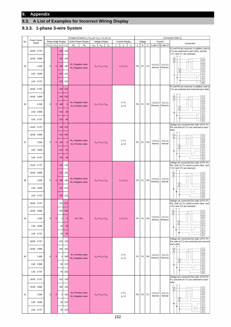
152
9. Appendix
9.3. A List of Examples for Incorrect Wiring Display
9.3.3. 1-phase 3-wire System
∠V1N ∠V3N ∠I1 ∠I3 W1 W3 V1N V3N V13 I1 IN I3 1 N 3 1 side CT 3 side CT
LEAD 0.707 135 135
LEAD 0.866 150 150
1.000 180 180
LAG 0.866 210 210
LAG 0.707 225 225
LEAD 0.707 135 315
LEAD 0.866 150 330
1.000 180 0
LAG 0.866 210 30
LAG 0.707 225 45
LEAD 0.707 135 315
LEAD 0.866 150 330
1.000 180 0
LAG 0.866 210 30
LAG 0.707 225 45
LEAD 0.707 135 135
LEAD 0.866 150 150
1.000 180 180
LAG 0.866 210 210
LAG 0.707 225 225
LEAD 0.707 315 315Voltage are connected the order of P3- P1-
PN, both of CTs switch to each other, and
‘+C3’ and ‘C3’ are reversed.
LEAD 0.866 330 330
1.000 0 0
LAG 0.866 30 30
LAG 0.707 45 45
LEAD 0.707 315 135
LEAD 0.866 330 150
1.000 0 180
LAG 0.866 30 210
LAG 0.707 45 225
LEAD 0.707 315 135
LEAD 0.866 330 150
1.000 0 180
LAG 0.866 30 210
LAG 0.707 45 225
No.Power Factor
(Input)
At balanced load (V1N=V3N (or V2N), I1=I3 (or I2)) Connection (Note 1)
Phase Angle Display Active Power Display Voltage Display Current Display Voltage CurrentConnection
36 0 0W1=Negative value
W3=Positive valueV1N=V13<V3N
35 0 0W1=Negative value
W3=Negative valueV1N=V13<V3N
I1=I3
IN=0PN P1 P3
+C3-C3
Reverse
+C1-C1
Reverse
PN P1 P3+C3-C3
Normal
+C1-C1
ReverseI1=I3<IN
38 0 0W1=Negative value
W3=Negative valueV1N=V13<V3N
37 0 0W1=Negative value
W3=Positive valueV1N=V13<V3N
I1=I3<IN P3 P1 PN+C3-C3
Reverse
+C1-C1
Normal
P3 P1 PN+C3-C3
Normal
+C1-C1
Normal
I1=I3
IN=0
40 0 0W1=Positive value
W3=Negative valueV1N=V13<V3N
39 0 0 W1<W3 V1N=V13<V3N
I1=I3
IN=0P3 P1 PN
+C3-C3
Reverse
+C1-C1
Reverse
P3 P1 PN+C3-C3
Normal
+C1-C1
ReverseI1=I3<IN
41 0 0W1=Positive value
W3=Negative valueV1N>V3N=V13
I1=I3
IN=0PN P3 P1
+C3-C3
Normal
+C1-C1
Normal
Voltage are connected the order of PN-P3-
P1, and both of CTs are switched to each
other.
P1 and PN are reversed, in addition, both of
CTs are switched to each other, and the
‘+C1’ and ‘C1’ are reversed.
P1 and PN are reversed, in addition, both of
CTs are switched and reversed each other.
Voltage are connected the order of P3- P1-
PN, both of CTs are switched and reversed
each other.
Voltage are connected the order of P3- P1-
PN, both of CTs switch to each other, and
‘+C3’ and ‘C3’ are reversed.
Voltage are connected the order of P3- P1-
PN, and both of CTs are switched to each
other.
+C2
C2
+C3
C3
P1
P3
P2
+C1
C1
PN
K
L
k
l
K
L
k
l
1 N 3
+C2
C2
+C3
C3
P1
P3
P2
+C1
C1
PN
K
L
k
l
K
L
k
l
1 N 3
+C2
C2
+C3
C3
P1
P3
P2
+C1
C1
PN
K
L
k
l
K
L
k
l
1 N 3
+C2
C2
+C3
C3
P1
P3
P2
+C1
C1
PN
K
L
k
l
K
L
k
l
1 N 3
+C2
C2
+C3
C3
P1
P3
P2
+C1
C1
PN
K
L
k
l
K
L
k
l
1 N 3
+C2
C2
+C3
C3
P1
P3
P2
+C1
C1
PN
K
L
k
l
K
L
k
l
1 N 3
+C2
C2
+C3
C3
P1
P3
P2
+C1
C1
PN
K
L
k
l
K
L
k
l
1 N 3
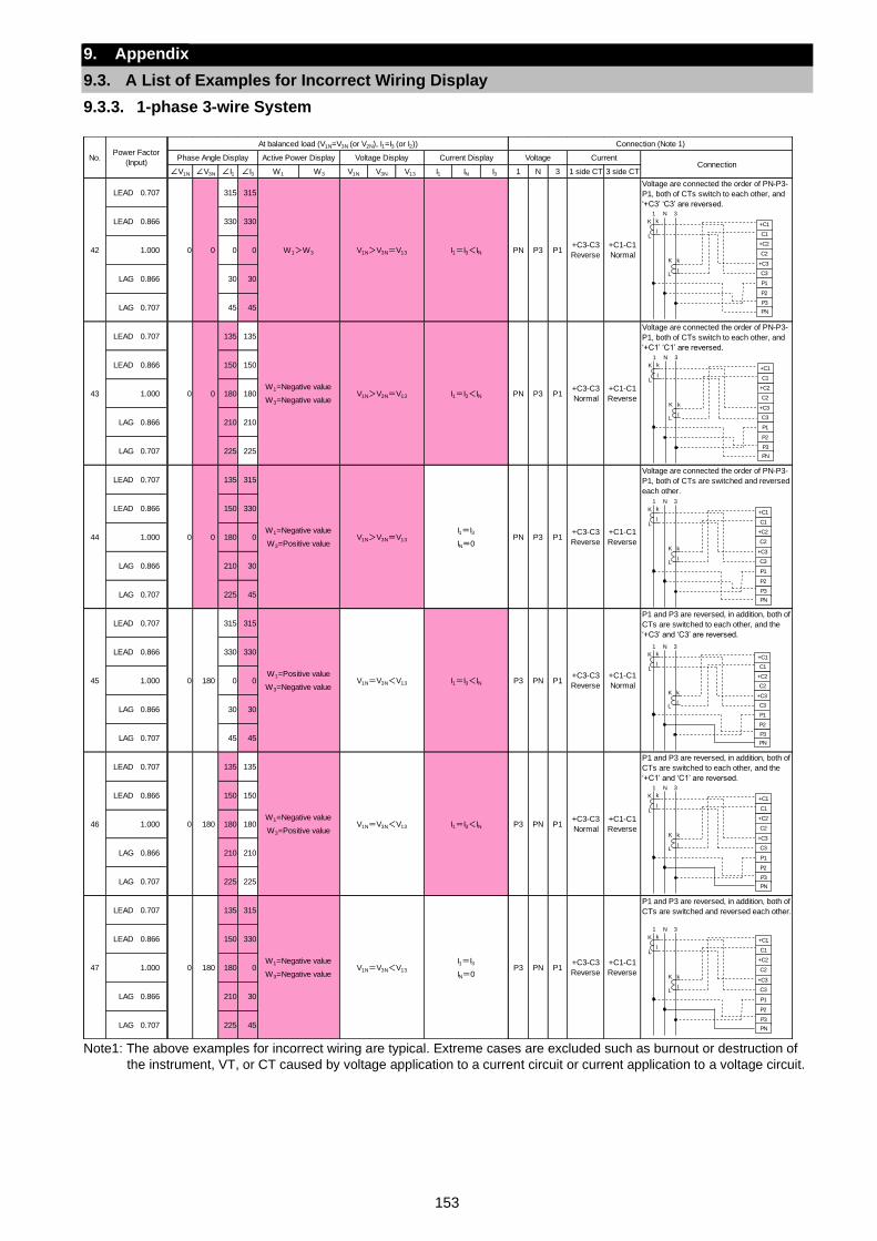
153
9. Appendix
9.3. A List of Examples for Incorrect Wiring Display
9.3.3. 1-phase 3-wire System
Note1: The above examples for incorrect wiring are typical. Extreme cases are excluded such as burnout or destruction of
the instrument, VT, or CT caused by voltage application to a current circuit or current application to a voltage circuit.
∠V1N ∠V3N ∠I1 ∠I3 W1 W3 V1N V3N V13 I1 IN I3 1 N 3 1 side CT 3 side CT
LEAD 0.707 315 315
LEAD 0.866 330 330
1.000 0 0
LAG 0.866 30 30
LAG 0.707 45 45
LEAD 0.707 135 135
LEAD 0.866 150 150
1.000 180 180
LAG 0.866 210 210
LAG 0.707 225 225
LEAD 0.707 135 315
LEAD 0.866 150 330
1.000 180 0
LAG 0.866 210 30
LAG 0.707 225 45
LEAD 0.707 315 315
LEAD 0.866 330 330
1.000 0 0
LAG 0.866 30 30
LAG 0.707 45 45
LEAD 0.707 135 135
LEAD 0.866 150 150
1.000 180 180
LAG 0.866 210 210
LAG 0.707 225 225
LEAD 0.707 135 315
LEAD 0.866 150 330
1.000 180 0
LAG 0.866 210 30
LAG 0.707 225 45
No.Power Factor
(Input)
At balanced load (V1N=V3N (or V2N), I1=I3 (or I2)) Connection (Note 1)
Phase Angle Display Active Power Display Voltage Display Current Display Voltage CurrentConnection
43 0 0W1=Negative value
W3=Negative valueV1N>V3N=V13
42 0 0 W1>W3 V1N>V3N=V13
I1=I3<IN PN P3 P1+C3-C3
Normal
+C1-C1
Reverse
PN P3 P1+C3-C3
Reverse
+C1-C1
NormalI1=I3<IN
45 0 180W1=Positive value
W3=Negative valueV1N=V3N<V13
44 0 0W1=Negative value
W3=Positive valueV1N>V3N=V13
I1=I3<IN P3 PN P1+C3-C3
Reverse
+C1-C1
Normal
PN P3 P1+C3-C3
Reverse
+C1-C1
Reverse
I1=I3
IN=0
47 0 180W1=Negative value
W3=Negative valueV1N=V3N<V13
46 0 180W1=Negative value
W3=Positive valueV1N=V3N<V13
I1=I3
IN=0P3 PN P1
+C3-C3
Reverse
+C1-C1
Reverse
P3 PN P1+C3-C3
Normal
+C1-C1
ReverseI1=I3<IN
Voltage are connected the order of PN-P3-
P1, both of CTs are switched and reversed
each other.
P1 and P3 are reversed, in addition, both of
CTs are switched to each other, and the
‘+C3’ and ‘C3’ are reversed.
P1 and P3 are reversed, in addition, both of
CTs are switched to each other, and the
‘+C1’ and ‘C1’ are reversed.
P1 and P3 are reversed, in addition, both of
CTs are switched and reversed each other.
Voltage are connected the order of PN-P3-
P1, both of CTs switch to each other, and
‘+C3’ ‘C3’ are reversed.
Voltage are connected the order of PN-P3-
P1, both of CTs switch to each other, and
‘+C1’ ‘C1’ are reversed.
+C2
C2
+C3
C3
P1
P3
P2
+C1
C1
PN
K
L
k
l
K
L
k
l
1 N 3
+C2
C2
+C3
C3
P1
P3
P2
+C1
C1
PN
K
L
k
l
K
L
k
l
1 N 3
+C2
C2
+C3
C3
P1
P3
P2
+C1
C1
PN
K
L
k
l
K
L
k
l
1 N 3
+C2
C2
+C3
C3
P1
P3
P2
+C1
C1
PN
K
L
k
l
K
L
k
l
1 N 3
+C2
C2
+C3
C3
P1
P3
P2
+C1
C1
PN
K
L
k
l
K
L
k
l
1 N 3
+C2
C2
+C3
C3
P1
P3
P2
+C1
C1
PN
K
L
k
l
K
L
k
l
1 N 3
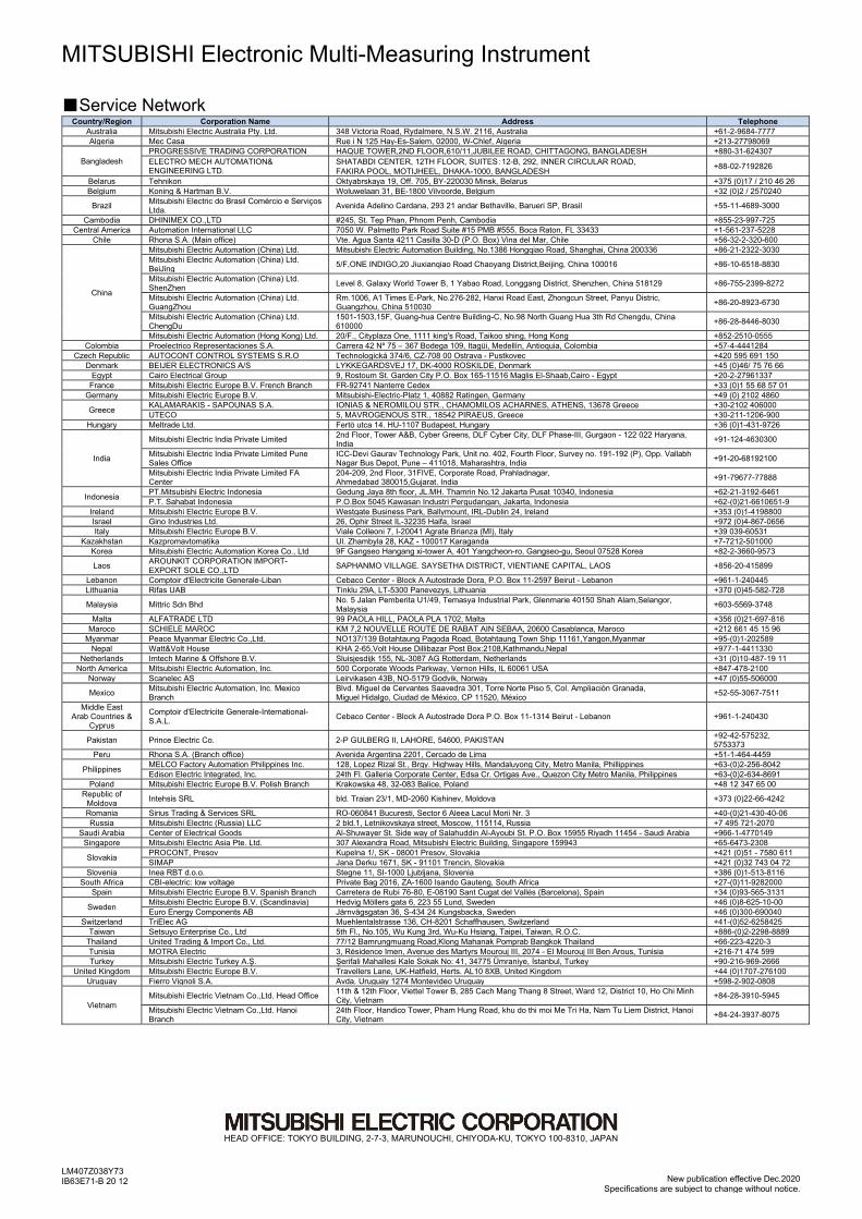
LM407Z038Y73 IB63E71-B 20 12 New publication effective Dec.2020
Specifications are subject to change without notice.
HEAD OFFICE: TOKYO BUILDING, 2-7-3, MARUNOUCHI, CHIYODA-KU, TOKYO 100-8310, JAPAN
MITSUBISHI Electronic Multi-Measuring Instrument Service Network
Country/Region Corporation Name Address Telephone Australia Mitsubishi Electric Australia Pty. Ltd. 348 Victoria Road, Rydalmere, N.S.W. 2116, Australia +61-2-9684-7777 Algeria Mec Casa Rue i N 125 Hay-Es-Salem, 02000, W-Chlef, Algeria +213-27798069
Bangladesh PROGRESSIVE TRADING CORPORATION HAQUE TOWER,2ND FLOOR,610/11,JUBILEE ROAD, CHITTAGONG, BANGLADESH +880-31-624307 ELECTRO MECH AUTOMATION& ENGINEERING LTD.
SHATABDI CENTER, 12TH FLOOR, SUITES:12-B, 292, INNER CIRCULAR ROAD, FAKIRA POOL, MOTIJHEEL, DHAKA-1000, BANGLADESH
+88-02-7192826
Belarus Tehnikon Oktyabrskaya 19, Off. 705, BY-220030 Minsk, Belarus +375 (0)17 / 210 46 26 Belgium Koning & Hartman B.V. Woluwelaan 31, BE-1800 Vilvoorde, Belgium +32 (0)2 / 2570240
Brazil Mitsubishi Electric do Brasil Comércio e Serviços Ltda.
Avenida Adelino Cardana, 293 21 andar Bethaville, Barueri SP, Brasil +55-11-4689-3000
Cambodia DHINIMEX CO.,LTD #245, St. Tep Phan, Phnom Penh, Cambodia +855-23-997-725 Central America Automation International LLC 7050 W. Palmetto Park Road Suite #15 PMB #555, Boca Raton, FL 33433 +1-561-237-5228
Chile Rhona S.A. (Main office) Vte. Agua Santa 4211 Casilla 30-D (P.O. Box) Vina del Mar, Chile +56-32-2-320-600
China
Mitsubishi Electric Automation (China) Ltd. Mitsubishi Electric Automation Building, No.1386 Hongqiao Road, Shanghai, China 200336 +86-21-2322-3030 Mitsubishi Electric Automation (China) Ltd. BeiJing
5/F,ONE INDIGO,20 Jiuxianqiao Road Chaoyang District,Beijing, China 100016 +86-10-6518-8830
Mitsubishi Electric Automation (China) Ltd. ShenZhen
Level 8, Galaxy World Tower B, 1 Yabao Road, Longgang District, Shenzhen, China 518129 +86-755-2399-8272
Mitsubishi Electric Automation (China) Ltd. GuangZhou
Rm.1006, A1 Times E-Park, No.276-282, Hanxi Road East, Zhongcun Street, Panyu Distric, Guangzhou, China 510030
+86-20-8923-6730
Mitsubishi Electric Automation (China) Ltd. ChengDu
1501-1503,15F, Guang-hua Centre Building-C, No.98 North Guang Hua 3th Rd Chengdu, China 610000
+86-28-8446-8030
Mitsubishi Electric Automation (Hong Kong) Ltd. 20/F., Cityplaza One, 1111 king's Road, Taikoo shing, Hong Kong +852-2510-0555 Colombia Proelectrico Representaciones S.A. Carrera 42 Nº 75 – 367 Bodega 109, Itagüi, Medellín, Antioquia, Colombia +57-4-4441284
Czech Republic AUTOCONT CONTROL SYSTEMS S.R.O Technologická 374/6, CZ-708 00 Ostrava - Pustkovec +420 595 691 150 Denmark BEIJER ELECTRONICS A/S LYKKEGARDSVEJ 17, DK-4000 ROSKILDE, Denmark +45 (0)46/ 75 76 66
Egypt Cairo Electrical Group 9, Rostoum St. Garden City P.O. Box 165-11516 Maglis El-Shaab,Cairo - Egypt +20-2-27961337 France Mitsubishi Electric Europe B.V. French Branch FR-92741 Nanterre Cedex +33 (0)1 55 68 57 01
Germany Mitsubishi Electric Europe B.V. Mitsubishi-Electric-Platz 1, 40882 Ratingen, Germany +49 (0) 2102 4860
Greece KALAMARAKIS - SAPOUNAS S.A. IONIAS & NEROMILOU STR., CHAMOMILOS ACHARNES, ATHENS, 13678 Greece +30-2102 406000 UTECO 5, MAVROGENOUS STR., 18542 PIRAEUS, Greece +30-211-1206-900
Hungary Meltrade Ltd. Fertö utca 14. HU-1107 Budapest, Hungary +36 (0)1-431-9726
India
Mitsubishi Electric India Private Limited 2nd Floor, Tower A&B, Cyber Greens, DLF Cyber City, DLF Phase-III, Gurgaon - 122 022 Haryana, India
+91-124-4630300
Mitsubishi Electric India Private Limited Pune Sales Office
ICC-Devi Gaurav Technology Park, Unit no. 402, Fourth Floor, Survey no. 191-192 (P), Opp. Vallabh Nagar Bus Depot, Pune – 411018, Maharashtra, India
+91-20-68192100
Mitsubishi Electric India Private Limited FA Center
204-209, 2nd Floor, 31FIVE, Corporate Road, Prahladnagar, Ahmedabad 380015,Gujarat. India
+91-79677-77888
Indonesia PT.Mitsubishi Electric Indonesia Gedung Jaya 8th floor, JL.MH. Thamrin No.12 Jakarta Pusat 10340, Indonesia +62-21-3192-6461 P.T. Sahabat Indonesia P.O.Box 5045 Kawasan Industri Pergudangan, Jakarta, Indonesia +62-(0)21-6610651-9
Ireland Mitsubishi Electric Europe B.V. Westgate Business Park, Ballymount, IRL-Dublin 24, Ireland +353 (0)1-4198800 Israel Gino Industries Ltd. 26, Ophir Street IL-32235 Haifa, Israel +972 (0)4-867-0656 Italy Mitsubishi Electric Europe B.V. Viale Colleoni 7, I-20041 Agrate Brianza (MI), Italy +39 039-60531
Kazakhstan Kazpromavtomatika Ul. Zhambyla 28, KAZ - 100017 Karaganda +7-7212-501000 Korea Mitsubishi Electric Automation Korea Co., Ltd 9F Gangseo Hangang xi-tower A, 401 Yangcheon-ro, Gangseo-gu, Seoul 07528 Korea +82-2-3660-9573
Laos AROUNKIT CORPORATION IMPORT- EXPORT SOLE CO.,LTD
SAPHANMO VILLAGE. SAYSETHA DISTRICT, VIENTIANE CAPITAL, LAOS +856-20-415899
Lebanon Comptoir d'Electricite Generale-Liban Cebaco Center - Block A Autostrade Dora, P.O. Box 11-2597 Beirut - Lebanon +961-1-240445 Lithuania Rifas UAB Tinklu 29A, LT-5300 Panevezys, Lithuania +370 (0)45-582-728
Malaysia Mittric Sdn Bhd No. 5 Jalan Pemberita U1/49, Temasya Industrial Park, Glenmarie 40150 Shah Alam,Selangor, Malaysia
+603-5569-3748
Malta ALFATRADE LTD 99 PAOLA HILL, PAOLA PLA 1702, Malta +356 (0)21-697-816 Maroco SCHIELE MAROC KM 7,2 NOUVELLE ROUTE DE RABAT AIN SEBAA, 20600 Casablanca, Maroco +212 661 45 15 96
Myanmar Peace Myanmar Electric Co.,Ltd. NO137/139 Botahtaung Pagoda Road, Botahtaung Town Ship 11161,Yangon,Myanmar +95-(0)1-202589 Nepal Watt&Volt House KHA 2-65,Volt House Dillibazar Post Box:2108,Kathmandu,Nepal +977-1-4411330
Netherlands Imtech Marine & Offshore B.V. Sluisjesdijk 155, NL-3087 AG Rotterdam, Netherlands +31 (0)10-487-19 11 North America Mitsubishi Electric Automation, Inc. 500 Corporate Woods Parkway, Vernon Hills, IL 60061 USA +847-478-2100
Norway Scanelec AS Leirvikasen 43B, NO-5179 Godvik, Norway +47 (0)55-506000
Mexico Mitsubishi Electric Automation, Inc. Mexico Branch
Blvd. Miguel de Cervantes Saavedra 301, Torre Norte Piso 5, Col. Ampliación Granada, Miguel Hidalgo, Ciudad de México, CP 11520, México
+52-55-3067-7511
Middle East Arab Countries &
Cyprus
Comptoir d'Electricite Generale-International-S.A.L.
Cebaco Center - Block A Autostrade Dora P.O. Box 11-1314 Beirut - Lebanon +961-1-240430
Pakistan Prince Electric Co. 2-P GULBERG II, LAHORE, 54600, PAKISTAN +92-42-575232, 5753373
Peru Rhona S.A. (Branch office) Avenida Argentina 2201, Cercado de Lima +51-1-464-4459
Philippines MELCO Factory Automation Philippines Inc. 128, Lopez Rizal St., Brgy. Highway Hills, Mandaluyong City, Metro Manila, Phillippines +63-(0)2-256-8042 Edison Electric Integrated, Inc. 24th Fl. Galleria Corporate Center, Edsa Cr. Ortigas Ave., Quezon City Metro Manila, Philippines +63-(0)2-634-8691
Poland Mitsubishi Electric Europe B.V. Polish Branch Krakowska 48, 32-083 Balice, Poland +48 12 347 65 00 Republic of
Moldova Intehsis SRL bld. Traian 23/1, MD-2060 Kishinev, Moldova +373 (0)22-66-4242
Romania Sirius Trading & Services SRL RO-060841 Bucuresti, Sector 6 Aleea Lacul Morii Nr. 3 +40-(0)21-430-40-06 Russia Mitsubishi Electric (Russia) LLC 2 bld.1, Letnikovskaya street, Moscow, 115114, Russia +7 495 721-2070
Saudi Arabia Center of Electrical Goods Al-Shuwayer St. Side way of Salahuddin Al-Ayoubi St. P.O. Box 15955 Riyadh 11454 - Saudi Arabia +966-1-4770149 Singapore Mitsubishi Electric Asia Pte. Ltd. 307 Alexandra Road, Mitsubishi Electric Building, Singapore 159943 +65-6473-2308
Slovakia PROCONT, Presov Kupelna 1/, SK - 08001 Presov, Slovakia +421 (0)51 - 7580 611 SIMAP Jana Derku 1671, SK - 91101 Trencin, Slovakia +421 (0)32 743 04 72
Slovenia Inea RBT d.o.o. Stegne 11, SI-1000 Ljubljana, Slovenia +386 (0)1-513-8116 South Africa CBI-electric: low voltage Private Bag 2016, ZA-1600 Isando Gauteng, South Africa +27-(0)11-9282000
Spain Mitsubishi Electric Europe B.V. Spanish Branch Carretera de Rubí 76-80, E-08190 Sant Cugat del Vallés (Barcelona), Spain +34 (0)93-565-3131
Sweden Mitsubishi Electric Europe B.V. (Scandinavia) Hedvig Möllers gata 6, 223 55 Lund, Sweden +46 (0)8-625-10-00 Euro Energy Components AB Järnvägsgatan 36, S-434 24 Kungsbacka, Sweden +46 (0)300-690040
Switzerland TriElec AG Muehlentalstrasse 136, CH-8201 Schaffhausen, Switzerland +41-(0)52-6258425 Taiwan Setsuyo Enterprise Co., Ltd 5th Fl., No.105, Wu Kung 3rd, Wu-Ku Hsiang, Taipei, Taiwan, R.O.C. +886-(0)2-2298-8889
Thailand United Trading & Import Co., Ltd. 77/12 Bamrungmuang Road,Klong Mahanak Pomprab Bangkok Thailand +66-223-4220-3 Tunisia MOTRA Electric 3, Résidence Imen, Avenue des Martyrs Mourouj III, 2074 - El Mourouj III Ben Arous, Tunisia +216-71 474 599 Turkey Mitsubishi Electric Turkey A.Ş. Şerifali Mahallesi Kale Sokak No: 41, 34775 Ümraniye, İstanbul, Turkey +90-216-969-2666
United Kingdom Mitsubishi Electric Europe B.V. Travellers Lane, UK-Hatfield, Herts. AL10 8XB, United Kingdom +44 (0)1707-276100 Uruguay Fierro Vignoli S.A. Avda. Uruguay 1274 Montevideo Uruguay +598-2-902-0808
Vietnam Mitsubishi Electric Vietnam Co.,Ltd. Head Office
11th & 12th Floor, Viettel Tower B, 285 Cach Mang Thang 8 Street, Ward 12, District 10, Ho Chi Minh City, Vietnam
+84-28-3910-5945
Mitsubishi Electric Vietnam Co.,Ltd. Hanoi Branch
24th Floor, Handico Tower, Pham Hung Road, khu do thi moi Me Tri Ha, Nam Tu Liem District, Hanoi City, Vietnam
+84-24-3937-8075