Embed Size (px)
Citation preview

8/4/2019 Electronic Products 5-16-2011
http://slidepdf.com/reader/full/electronic-products-5-16-2011 1/13 LVisit www.GemsSensors.com for most current information.
GEMS Relays and Barriers Render AnyNon-Voltage Producing Sensor or SwitchIntrinsically Sae
Provide method o eliminating explosive conditions
Rapid, arc-ree response provides positive,non-mechanical operation
Solid-state reliability assures consistent perormance Low-power switching; a ew milliamps o current
controls high-power loads Completely encapsulated construction
Units are impervious to dust, moisture or oreign materialThey are tamper-proo and shock- and vibration-resistant
Modular housings or easier installation Exceptionally long, trouble-ree service lie
SOLID STaTE RELayS aND baRRIERS
Intrinsic Saety and its Advantages.Instrument Society o American Specifcation ISA-RP12.2Defning Intrinsically Sae Equipment:
“Intrinsically sae equipment and wiring is equipment and wiring whichis incapable o releasing sucient electrical or thermal energy undernormal or abnormal conditions to cause ignition o a specic hazardousatmospheric mixture in its most ignited concentration. Intrinsically saeterminations and wiring may be brought into any hazardous locationo any Group classication or which it is accepted without requiringexplosion-proo housing or other means o protection.”
To be certied “intrinsically sae,” a device or circuit must be sodesigned that no two simultaneous ailures can cause an explosion.Intrinsically sae systems are more dependable. The I.S. circuit mustunction reliably per specications, with no explosions, during and atercycling through a number o operations.
The units can also be installed more conveniently. Since no explosionis possible, no explosion-proo conduit or enclosures o any kindare needed in the hazardous area. Maintenance can be perormedimmediately as needed. And, intrinsically sae systems are moreeconomical. Costly enclosures with their mounting requirements areunnecessary. No purging is required, thereby eliminating blowers,pressure switches, timers and relays.
SAFE-PAK® RELAYS: These intrinsically sae units ampliy sensorload-handling capabilities in a wide diversity o AC and DC control
switching applications.
Zener Barriers: These passive, energy-limiting devices, provideintrinsically sae DC outputs or a variety o sensors such as level andfow switches…level indicating transducers and transmitters…andmany others. The maximum energy possible at the switch terminalso the SAFE-PAK and Zener Barriers is ar below the explosive point othe most volatile surrounding gas conditions. The type o non-voltage-producing switch or sensor best suited or the application can beutilized, since the entire switching circuit is rendered intrinsically sae bythe SAFE-PAK or Zener Barrier. As the switching circuit is low voltage,there is no shock hazard to operating or maintenance personnel.

8/4/2019 Electronic Products 5-16-2011
http://slidepdf.com/reader/full/electronic-products-5-16-2011 2/13L-2
ELECTRONIC
PRODUCTS
Visit www.GemsSensors.com for most current information.
ModelPart
Number
Approvals Hazardous LocationsPage
NumberUL FM CSA Class DivisionGroup
A B C D E F G
SAFE-PAK®
22445 • • •
I, II 1, 2
• • • • • • •
L-4
andL-5
25872 • • • • • • • • • •
25873 • • • • • • • • • •64101 • • • • • • • • •144600 • • • • • • • • • •
ProgrammableSAFE-PAK®
54820 • • •I, II 1, 2
• • • • • • • L-6andL-7
54825 • • • • • • • • • •54845 • • • • • • • • • •
ZenerBarriers2
54801 • • •
I, II 1, 2
•L-10andL-11
54803 • • • • • • •54805 • • • • • • •54806 • • • •111950 • • •
I, II 1, 2
• • • • • •
L-8andL-9
111952 • • • • • • • • •111954 • • • • • • • • •111956 • • • • • • • • •113000 • • • • • • •114072 • • • • • • •114074 • • • • • • •114166 • • • • • • • • •114175 • • • • • • •
LOAD
SAFE-PAK
FLOW SWITCH
SAFE-PAK
LEVEL SWITCH
SAFE-PAK
PD SWITCH
LATCHING
SAFE-PAK
VACLOAD
VACLOAD
VACLOAD
VAC
LEVEL SWITCH
Typical ApplicationsSwitches Located in Hazardous Areas
Important points to rememberwhen selecting Zener Barriers and Safe Pak® :•Themaximuminputvoltageratingofthebarrier
mustbehigherthanyourpowersupply. (i.e.,a24VDCsupplywouldrequirea30Vbarrier.)
•Makesurethebarrierisratedforyourhazardousareaclass,division,andgroup.
Intrinsic Safety Approvals –Safe-Pak® Relays and Zener Barriers
Notes:1. CertiedintrinsicallysafeunderMSHAcerticationNo.1662foruseonpermissibleequipment.
ForGroupDuseonly.2. ZenerBarriermodels,PartNumbers54801,54803,54805,54806;ProgrammableSAFE-PAKmodels,
PartNumbers54820,54825,54845arecertiedbyCSAformountinginsideasuitableenclosurein
Division2ornon-hazardouslocationsandmustbeconnectedbymeansofthetwostudsprovidedtogroundedcopperbusbarorequivalent.
Forinformationonnon-intrinsicallysafeholdingrelaysandswitchingunits,seePagesL-12andL-13.
MSHA —BureauofMines
UL —Underwriter’sLaboratories,Inc.
FM —FactoryMutualCSA —CanadianStandardsAssociation

8/4/2019 Electronic Products 5-16-2011
http://slidepdf.com/reader/full/electronic-products-5-16-2011 3/13LVisit www.GemsSensors.com for most current information.
EARTH GROUND2 PLACES
NON-INTRINSICALLYSAFE WIRING
RESISTANCE TOGROUND MUST BEFROM BRACKET TOEARTHING MEMBERTO ENSUREINTEGRITY OFSYSTEM (MUST BELESS THAN 1Ω
EARTH-GROUNDEDMOUNTING PLATE
INTRINSICALLYSAFE WIRING TO
SENSORS
INTRODUCTION
Installation and MaintenanceSAFE-PAK and Zener Barrier units are installed in a sae area andconnected to the sensor in a hazardous location…no explosion-proo orprotective housings o any kind are needed. Units install singly, in anyposition…or can be grouped on a common, earth-grounded plate withmounting tabs to provide electrical grounding. No. 6-32 threaded
electrical terminals are conveniently placed atop the unit housings.Barriers and relays may be grouped on a common, earth-groundedmounting plate. Intrinsically sae sensor wiring must be separated romnon-intrinsically-sae input wiring in separate conduits or raceways toprevent by-pass during testing or servicing.
Typical Common
Grouping
The only maintenance normally required is routine inspectionapproximately every two years or less to check integrity o earth-grounding and electrical connections, and to make sure the unit is clean.
GEMS SAFE-PAKS and Zener Barriers must be installed in conormancewith the National Electrical Code and the INSTRUCTION, INSTALLATION
AND SERVICE Bulletin supplied with all units. Periodic checks o groundbonding and cleanliness o units and terminals constitute the onlymaintenance required.
Warning
Misapplication o intrinsically sae products may result in injuries ordamages. The circuit diagrams presented in this catalog are typical andmay not represent your application.
Hazardous Locations as defnedby the National Electrical CodeHandbook. . .
The degree o hazard is normally indicated bya three-part designation: “Class-, Division, andGroup-.” Class I, Division 1, Group A denotesthe most severely and continually hazardouscondition.
Class I Locations — Are those in whichammable bases or vapors are or may bepresent in the air in quantities sufcient toproduce explosive or ignitable mixtures.
Class II Locations — Are those which arehazardous because o the presence ocombustible dust.
Class III Locations — Are those which arehazardous because o the presence o easily
ignitable fbers or yings, but in whichsuch fbers or yings are not likely to bein suspension in air quantities sufcient toproduce ignitable mixtures.
Division 1 — Locations in which hazardousconcentrations in the air exist continuously,intermittently, or periodically under normaloperating conditions.
Division 2 — Locations in which hazardousconcentrations are handled, processed, orused, but are normally confned within closedcontainers or closed systems rom which theycan escape only in case o accidental ruptureor breakdown.
Group A — Atmospheres containingacetylene.
Group B — Atmospheres containinghydrogen, or gases or vapors o equivalenthazard, such as manuactured gas.
Group C — Atmospheres containing ethyl-ether vapors, ethylene or cyclopropane.
Group D — Atmospheres containing gasoline,
hexane, naphtha, benzine, butane, propane,alcohol, acetone, benzol, lacquer solventvapors or natural gas.
Group E — Atmospheres containing metaldust, including aluminum, magnesium, andtheir commercial alloys and other metals osimilarly hazardous characteristics.
Group F — Atmospheres containing carbonblack, coal or coke dust.
Group G — Atmospheres containing our,starch, or grain dusts.

8/4/2019 Electronic Products 5-16-2011
http://slidepdf.com/reader/full/electronic-products-5-16-2011 4/13L-4
ELECTRONIC
PRODUCTS
Visit www.GemsSensors.com for most current information.
SAFE-PAK SAFE-PAK P/N 144600
RelayStyle
Operating &Load Voltage
Range
LoadCurrent
Maximum
Turn-OnSensitivity(Typical)1
Turn-OffSensitivity(Typical)1
VoltageLoss
OperatingTemperature
Range
Output LeakageCurrent
Maximum
SwitchingOperation
PartNumber
SAFE-PAK®
95 to 135VAC
5A 400 K 1 M Ω 2 VAC0°F to +120°F
(-17.8°C to +48.9°C)
6 mA@ 120 VAC
SPST N.O. 224455
100 to 135VAC
6 mA@ 120 VAC
SPST N.C. 258725
200 to 250VAC
12 mA@ 250 VAC
SPST N.O. 25873
Low Sensitivity
SAFE-PAK®
110 to 130VAC
.5A @ 20 VAC2
.05A @ 200 VAC2 300 1000 Ω —-10°F to +140°F
(-23.3°C to +60°C)0 SPST N.O. 64101
105 to 125VAC
5A 500 2000 Ω 2 VAC -40°F to +120°F(-40°C to +48.9°C)
6 mA@ 120 VAC
SPST N.O. 144600
7/32˝ DIA. (5.5 mm)
3-1/8˝ (79.4 mm)
1-5/8˝ (41.3 mm)
2-1/4˝ (57.2 mm)
13/16˝ (20.7 mm)
MOUNTING TAB
2-5/8˝ (66.6 mm)
3˝ (76.2 mm)
2-5/8˝
(66.6 mm)
3˝
(76.2 mm)
7/32˝ DIA.(5.5 mm)
MOUNTING TAB
1-3/8˝ (35 mm)
1-5/16˝ (33.3 mm)
7/8˝ (22.2 mm)
2-7/8˝ (73 mm)
®
Intrinsically SAFE-PAK® Relays AmplifySensor Load-Handling Capabilities
Costly explosion-proo enclosures with their mounting requirements are unnecessary.No purging is required.
SAFE-PAK: Less than 100 microamps at 9 VDC actuates the unit to control loads to
5A at 120 VAC. Resistive (up to 100,000Ω ) or short-circuiting sensors operate theunit. 120 VAC and 240 VAC model.
Low Sensitivity SAFE-PAK: Sensor closures up to 1000Ω resistance control resistiveloads to 5A at 120 VAC. 120 VAC, N.O. model.
See table on Page L-2 or specifc approval inormation.
Dimensions
How To OrderSelect Part Number based on Relay Style, Operating Voltage and Switch Operation required.
P/N22445258722587364101
P/N144600
Notes:1. Temperature Dependent.2. 50-60 Hz3. All AC voltage and current specifcations are RMS values unless otherwise stated.4. Housing material is Polysulone.5. Certifed intrinsically sae under MSHA certifcation No. 1662 or use on permissible equipment.
For Group D use only.
– Stock Items.

8/4/2019 Electronic Products 5-16-2011
http://slidepdf.com/reader/full/electronic-products-5-16-2011 5/13LVisit www.GemsSensors.com for most current information.
BLACK
RED
N.O. DRYOR
N.C. DRY
NON-HAZARDOUSAREA
FUSE
FUSE
LOAD
SAFE-PAK
HOT VACNEUTRAL VAC
HAZARDOUSAREA
–
BLACK
RED
N.O. DRYOR
N.C. DRY
NON-HAZARDOUSAREA
LOADSAFE-PAK
HOT VAC
NEUTRAL VAC
HAZARDOUSAREA
INTRINSICaLLy SafE RELayS
Typical Wiring Diagrams
SAFE-PAK, Part Numbers 25872, 25873, 64101 or 144600with sensor switch in hazardous location.
Transient Protection for SAFE-PAK (AC Loads) Use a properly sizedmetal oxide varistor (MOV) as shown below.
Installation and maintenance must be in accordance with the National ElectricalCode and the applicable GEMS INSTRUCTION, INSTALLATION and SERVICE bulletinavailable at www.gemssensors.com

8/4/2019 Electronic Products 5-16-2011
http://slidepdf.com/reader/full/electronic-products-5-16-2011 6/13L-6
ELECTRONIC
PRODUCTS
Visit www.GemsSensors.com for most current information.
PartNumber
OperatingVoltage4
LoadCurrent
Maximum
LoadVoltageRange
Turn-OnSensitivity(Typical)1
Turn-OffSensitivity(Typical)1
Leakage Current“Off” State,Maximum
VoltageLoss.
Maximum
TransientCurrent3
OperatingTemperature
Range
54820
95 to 125 VAC,50-60 Hz
2A25-250 VAC
50-60 Hz≤400 K Ω 1 M Ω 3 mA 2 V 20A
+32°F to+140°F
(0°C to 60°C)54825
0.5A @ 20 V.05A @ 200 V
AC or DC
0-250 VAC50-400 Hz0-200 VDC
≤30 K Ω 60 K Ω — — —
OPTIONAL
RAILMOUNTINGCLIP-P/N 61783
EARTH-GROUNDEDRAIL
5-1/2˝ (139.7 mm)
6˝ (152.4 mm)
1-5/8˝ (41.3 mm)
NO. 6-32THREADTYPICAL 4-3/4˝
(120.6 mm)
7/32˝ (5.5 mm)DIA. 3 MTG. HOLES
MOUNTING
TAB
HOUSING
RAIL-MOUNTINGCLIP OPTIONAL.CATALOG NO.61783
2-3/4˝ (69.8 mm)
8
7
6
5
4
3
2
1
OUTPUT
TERMINAL
COVER
Defne Switching Mode Anytime WithProgrammable SAFE-PAK® Relays
Provide normally open (N.O.), normally closed (N.C.) or latchingoutput with variable time delays
Designed or use with switches or sensors monitoring ow,pressure, level, etc
They render non-voltage-producing sensors intrinsically saeor operation in potentially hazardous areas
Streamlined housing suited or group-mountingon a common earth-grounded plate or multiple installation
UL recognized, FM, CSA and evaluated by MSHA
Operations such as normally open, normally closed or latching are programmed intothese versatile SAFE-PAK units by the user during installation. Selection is madeby simply connecting sensor wiring (and jumper wire when required) to the properterminals on the unit as diagrammed on opposite page. All units are programmable,except where otherwise indicated.See table on Page L-2 or specifc approval inormation.
OptionsSAFE-PAK Relays can be supplied with any o theollowing options on special order. Please consultactory.
• Withopticallyisolatedoperation
• Withzero-crossoverloadswitching
• Longertimedelays
• Rail-mountingclip(inadditiontostandardmounting tabs)
Specifcations
MSHA
Dimensions
Protective CoverAssures intrinsic saety integrity o sensor terminalsand wiring.
Notes:1. Temperature Dependent.2. Housing material is blue Lexan®.3. Repetitive surge currents caused by transient voltage/current pulses may eventually cause permanent
damage to triac-type switches i adequate transient suppression is not utilized.4. All AC voltage and current specifcations are RMS values unless otherwise stated.
– Stock Items.
8/4/2019 Electronic Products 5-16-2011
http://slidepdf.com/reader/full/electronic-products-5-16-2011 7/13LVisit www.GemsSensors.com for most current information.
Description – Hybrid Relay Switching Mode Part Number
Triac Output, AC OperationProgrammable,
N.O., N.C.,or latching
54820
Reed Switch Output, AC/DC Operation 54825
Optional Rail Mounting Clip 61783
SENSORSWITCH VAC
F1-SLO-BLO, .5 AMP
LOADOPERATINGVOLTAGE
68
57
24
13
N.O.LOAD
2468
1357
SENSORSWITCH
VAC
F1-SLO-BLO, .5 AMP
LOADOPERATINGVOLTAGE
N.O.
JUMPERLOAD
2468
1357
SENSORSWITCHES
VAC
F1-SLO-BLO, .5 AMP
LOADOPERATINGVOLTAGE
JUMPER
N.O. (DRY)
N.C. (DRY)LOAD
HI
LO
2468
1357
SENSOR
SWITCHES
VAC
F1-SLO-BLO, .5 AMP
LOADOPERATINGVOLTAGE
N.C.
N.O.LOAD
SAFE-PAK
1234
COM.
INDUCTIVELOAD
+ VDCSAFE-PAK
1234
COM.INDUCTIVELOAD
+ VDC
-
-
-
-
LOAD CONNECTEDTO TERMINAL 3
LOAD CONNECTEDTO TERMINAL 4
SAFE-PAKP/N
54820
1234
AC AC
INDUCTIVELOAD
MOV
- -
HAZARDOUSAREA
NON-HAZARDOUSAREA
P.C.
SAFE-PAK
SENSOR *
INPUT
120 VA2468
1357
-
-
PROgRammabLE RELayS
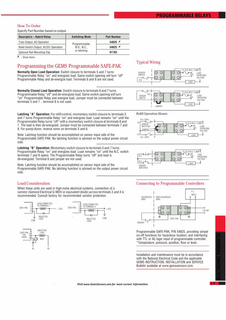
How To OrderSpeciy Part Number based on output.
– Stock Items.
Programming the GEMS Programmable SAFE-PAKNormally Open Load Operation: Switch closure to terminals 5 and 7 turnsProgrammable Relay “on” and energizes load. Same switch opening will turn “o”Programmable Relay and de-energize load. Terminals 6 and 8 are not used.
Normally Closed Load Operation: Switch closure to terminals 6 and 7 turnsProgrammable Relay “o” and de-energizes load. Same switch opening will turn“on” Programmable Relay and energize load. Jumper must be connected betweenterminals 5 and 7…terminal 8 is not used.
Latching “A” Operation: For rell control, momentary switch closure to terminals 5and 7 turns Programmable Relay “on” and energizes load. Load remains “on” until theProgrammable Relay turns “o” with a momentary switch closure at terminals 6 and7. The load is then de-energized. Jumper must be connected between terminals 7 and8. For pump-down, reverse wires on terminals 5 and 6.
Note: Latching unction should be accomplished on sensor input side o theProgrammable SAFE-PAK. No latching unction is advised on the output power circuitside.
Latching “B” Operation: Momentary switch closure to terminals 5 and 7 turnsProgrammable Relay “on” and energizes load. Load remains “on” until the N.C. switchterminals 7 and 8 opens. The Programmable Relay turns “o” and load isde-energized. Terminal 6 and jumper are not used.
Note: Latching unction should be accomplished on sensor input side o the
Programmable SAFE-PAK. No latching unction is advised on the output power circuitside.
Typical Wiring
Refll Operation Shown
Load ConsiderationWhen these units are used in high-noise electrical systems, connection o avaristor (General Electrical G-MOV or equivalent diode) across terminals 3 and 4 isrecommended. Consult actory or recommended varistor protection.
Connecting to Programmable Controllers
Programmable SAFE-PAK, P/N 54825, providing simpleon-o unctions or hazardous location, and interacingwith TTL or AC logic input o programmable controller.*Temperature, pressure, position, fow or level.
Installation and maintenance must be in accordancewith the National Electrical Code and the applicableGEMS INSTRUCTION, INSTALLATION and SERVICEBulletin available at www.gemssensors.com

8/4/2019 Electronic Products 5-16-2011
http://slidepdf.com/reader/full/electronic-products-5-16-2011 8/13L-8
ELECTRONIC
PRODUCTS
Visit www.GemsSensors.com for most current information.
SAFE AREAHAZARDOUS AREA
SENSORZENER BARRIER
FUSE
POWERSUPPLY
ANNUNC.
( + )
( – )
1
2
3
2
FUSE*
HAZARDOUSAREA
NON-HAZARDOUSAREA
DC POWERSUPPLY
SIGNALRETURNBARRIER
( + )
( - )
2 13
2 13 LOAD
31/64˝ (12.3 mm)
RED POLYSULFONE HOUSING
1-7/16˝ (36.5 mm)
3-3/16˝ (80.9 mm)
MOUNTING SCREW LOCATING PIN
25˝
64
1˝
(25,4) (9,92)
.123 (3,12) DIA. MAX.13˝ 64
(5,16)
EARTH-GROUNDEDRAIL
OPTIONALRAILMOUNTINGCLIP-P/N 113530
65800 Series Single Channel Zener BarriersRender Switches or Signal Conditioners Intrinsically Safe
Limits D.C. voltage and current to the hazardous areaand provides a path for fault current
Intrinsic saety with solid-state reliability Compact size streamlines installation Space-saving in multiples Encapsulated construction is impervious to dust and moisture
The exceptionally compact design o GEMS 65800 Series units saves space andsimplies installation; especially in multiples on a common mounting plate. Theyprovide great economy as well since no explosion-proo enclosures are needed orsensor wiring. Encapsulated construction is impervious to dust and moisture. Single-screw mounting is standard, but units can be supplied with an optional clip or railmounting. The single through-mounting screw also provides electrical connection toground through the earth-grounded mounting surace.
Any non-voltage-producing sensor or switch is rendered intrinsically sae orhazardous locations when properly connected to the output o these Zener Barriers.
See table on Page L-2 or specic approval inormation.
Typical Wiring Diagram
Positive single-channel Zener Barrier with negative ground.For most non-voltage-producing devices located in a hazardous area, a single ZenerBarrier that is negative-earth-ground can be used or intrinsic saety. Instrumentationthat produces an output (signal conditioners) usually requires two barriers, one oreach “foating” lead. In this case, a dual channel barrier can be provided (see L-10 andL-11).
Or, or applications where the instrument signal return level cannot be reduced, asupply barrier and a low resistance return barrier can be supplied (shown below).
For foating leads: 65800 Series supply and return barriers or signal conditioners.
Installation and maintenance must be in accordance with the National ElectricalCode and the applicable Gems INSTRUCTION, INSTALLATION and SERVICE bulletinavailable at www.gemssensors.com
Only 2.5 oz.
Dimensions
Protective CoverProtective cover over the output terminal (3) assuresintrinsic saety o sensor wiring.
Optional Rail MountingGems Single Channel Zener Barriers can be supplied onspecial order with a clip or rail mounting. Clip attachesto barrier with standard mounting screw.

8/4/2019 Electronic Products 5-16-2011
http://slidepdf.com/reader/full/electronic-products-5-16-2011 9/13LVisit www.GemsSensors.com for most current information.
ZenerBarrierType
DC Input to Barrier,Max. Signal
Polarity
SeriesResistance
ohms
ApplicationGroup
Reactive LimitsPart
NumberCapacitanceµf
InductancemhVoltage Current
Supply
+15 250 mA
Positive
183
A, B, C, D,E, G
0.32 2.0 111950
+20 125 mA 303 0.18 4.1 111952
+24 62 mA 390 0.12 3.0 111954
+30 62 mA 750 0.07 1.8 111956
+18 125 mA 183
C, D, E, G
0.72 3.6 114074
+24 62 mA 234 0.33 3.1 114072
+27 62 mA 276 0.24 3.3 114175
+30 250 mA 303 0.20 3.0 113000
Signal Return +30 250 mA 33.9 A, B, C, D, E, G 0.07 .35 114166
Optional Rail Clip 113530
FUSE*
HAZARDOUSAREA
NON-HAZARDOUSAREA
DC POWERSUPPLY,ANNUNC.
SENSOR,SINGLESTATIONSWITCH
( + )
( - )DC POWERSUPPLY,ANNUNC.
( + )
( - )2 13
HAZARDOUSAREA
NON-HAZARDOUSAREA
SUPPLYBARRIER
( + )
2 13
2 13
GEMSFLOWSWITCH
SUPPLY
BARRIER
NO FLOW FLOW
COM.
HAZARDOUSAREA
NON-HAZARDOUSAREA
RETURNBARRIER
2 13
2 13
RED (+)
OUTPUTWHITE
SUPPLYBARRIER
HAZARDOUSAREA
NON-HAZARDOUSAREA
2 13
2 13
2 13
RETURN
RETURN
SUPPLY
OPTOCOUPLER
OPTOCOUPLER
+5 VDC
ZENERBARRIERS
MICROPROCESSOR
BLACK (-)
zENER baRRIERS
How To OrderSpeciy Part Number based on Barrier Type and Input Power requirements.
Notes:1. All models shown are or Class I and II, Division 1 and 2. Specic Application Groups are tabulated.2. Ambient operating temperatures or all models shown is -40°F to +140°F (-40°C to +60°C).
– Stock Items.
Typical Application ExamplesSensors or Switches may be any non-voltage-producing device. Typical are: fow andlevel switches, temperature switches (thermostats), pressure switches or passiveresistive transducers or transmitters. Below are typical examples.
*Littleuse type 3AG or equal—optional.
With GEMS level switch or any other non-voltage-producingdevice located in a hazardous area.
Supply and Return Zener Barriers used with GEMS ELS-1100Series electro-optical level switch.
For optically coupled microprocessor. 65800 Series supply withtwo return barriers or SPDT switch.
Used with GEMS fow switch located in a hazardous area or fow/ no fow indication.

8/4/2019 Electronic Products 5-16-2011
http://slidepdf.com/reader/full/electronic-products-5-16-2011 10/13L-10
ELECTRONIC
PRODUCTS
Visit www.GemsSensors.com for most current information.
OPTIONALRAILMOUNTINGCLIP-P/N 61783
EARTH-GROUNDEDRAIL
5-1/2˝ (139.7 mm)
6˝
(152.4 mm)
1-5/8˝ (41.3 mm)
NO. 6-32THREADTYPICAL 4-3/4˝
(120.6 mm)
7/32˝ (5.5 mm)DIA. 3 MTG. HOLES
MOUNTINGTAB
HOUSING
FULL REF. SWITCH(P/N 54805 ONLY)
RAIL-MOUNTINGCLIP OPTIONAL.CATALOG NO.61783
2-3/4˝ (69.8 mm)
8
7
6
5
4
3
2
1
OUTPUT
TERMINAL
COVER
SAFE AREAHAZARDOUS AREA
SIGNALCONDITIONER
ZENER BARRIER
FUSE
POWERSUPPLY
ANNUNC.
( + )
( – )
1
3
7
5
46
28
54800 Series Dual Channel Zener BarriersProvide Intrinsic Safety to Signal Producing Sensors
Intrinsic saety with solid-state reliability Since no explosion-proo enclosures are needed or sensor wiring,
these units urther provide economical installation With encapsulated construction, 54800 Series Barriers are
impervious to dust and moisture Optional clip available or rail mounting
For most non-voltage-producing devices located in a hazardous area, a single zenerbarrier that is negative-earth-grounded (see preceding two pages) can be used orintrinsic saety.
Instrumentation that produces an output (signal conditioners) usually requires twobarriers, one or each “oating” lead. In this case, select one o the 54800 Series dualchannel barriers shown here.
Any non-voltage-producing sensor or switch is rendered intrinsically sae orhazardous locations when properly connected to the output o these Zener Barriers.
See table on Page L-2 or specifc approval inormation.
Optional Rail MountingGems SAFE-PAK Relays can be supplied on specialorder with a clip or rail mounting. Clip is in addition tostandard mounting tabs.
Dimensions
Protective CoverAssures intrinsic saety integrity o sensor terminalsand wiring.
Typical Wiring DiagramPositive dual-channel Zener Barrier with oating leads.

8/4/2019 Electronic Products 5-16-2011
http://slidepdf.com/reader/full/electronic-products-5-16-2011 11/13LVisit www.GemsSensors.com for most current information.
DC Input toBarrier, Max.
SignalPolarity
Total SeriesResistancePer Channel
ApplicationGroup
Reactive LimitsPart
NumbersCapacitanceµf
Inductancemh
15 VDC, 200 mA Positive 65 D 5.6 0.7 54801
20 VDC, 100 mA Positive 270A, B 0.4 0.9
54803C 1.2 5.0
D 3.2 10.0
20 VDC, 100 mA(Full Re. Sw.)
Positive 270
A, B 0.4 0.9
54805C 1.2 5.0
D 3.2 10.0
30 VDC, 60 mA Positive 275 D 2.4 6.0 54806
Optional Rail Mounting Clip 61783
-
-
-
HAZARDOUSAREA
NON-HAZARDOUSAREA
GEMSXM-SERIESTRANSMITTER
BLK
RED
WH
GEMS TLIRECEIVER
ZENER BARRIERSAFE-PAK
FULL REF.SWITCH
A
B
C
2468
1357
-
-
-
,
-
-
-
-
-
-
-
-
-
HAZARDOUSAREA
NON-HAZARDOUSAREA
2468
1357
ZENER BARRIERSAFE-PAK(POSITIVE TYPE)
STUD COVER MUST BE IN PLACEWHEN BARRIER IS IN USE
PROCESSCONTROLTRANSMITTER(GEMS XT-SERIESTRANSMITTER)
ACINPUTSOURCE **
TERM. EQUIP.(BY CUST.)
** INPUT POWER FROMSOURCE NOT GREATERTHAN 250 VAC
V +COM.
RL
DUaL ChaNNEL zENER baRRIERS
How To OrderSpeciy Part Number based on the specications tabulated below.
Notes:1. These barriers are internally used. I a “ault” or abnormal signal level continues or a sustained period o
time, the internal using within the barrier will open, disconnecting the barrier. External uses (LittleuseType 3AG or equal) are recommended to protect the Barrier rom incorrect wiring at start-up, or rom otherequipment ault.
2. Housing material is blue Lexan®.3. All models shown are or Class I and II, Division 1 and 2. Specic Application Groups are tabulated.4. Ambient operating temperature or all models shown is -40°F to +140°F (-40°C to +60°C).5. Terminals 3, 4, 5 and 6 are common and are bonded to the mounting tabs or positive redundant grounding.
– Stock Items.
Installation and maintenance must be in accordance with the National ElectricalCode and the applicable GEMS INSTRUCTION, INSTALLATION and SERVICE Bulletinavailable at www.gemssensors.com
Typical Application ExamplesSensor switch may be any non-voltage-producing device. Typical are: fow and levelswitches, temperature switches (thermostats), pressure switches or passive, resistivetransducers or transmitters. Below are typical examples.
P/N 54805 in a continuous liquid level monitoring system.
Note: Terminals 3, 4, 5 and 6 are common and are bonded to the mounting tabsor positive redundant grounding.
P/N 54806 in process control system.
To Determine Loop Resistance:
*VA
must be less than 28 VDC (30 Volt Barriers)
R Loop = ; R Loop =V
A* - 10
.02
RSUPPLY
+ RRETURN
+ RMONITORING
BARRIER BARRIER EQUIPMENT

8/4/2019 Electronic Products 5-16-2011
http://slidepdf.com/reader/full/electronic-products-5-16-2011 12/13L-12
ELECTRONIC
PRODUCTS
Visit www.GemsSensors.com for most current information.
LOAD-PAK, 5 Amp. A.C.LOAD-PAK, 10 Amp, A.C.LOAD-PAK, 2 Amp, D.C.
SPDT-PAK, FLIP-PAK
1-9/16˝ (39.6 mm)
7/32˝ (5.5 mm)
DIA. 2 HOLES.
2-3/4˝ (69.8 mm)MTNG. CTRS.
1˝ (25.4 mm)
6-32 THD.
- ˝
- ˝
- ˝
˝
2-3/8˝ (60.3 mm)
- ˝
-
- ˝
˝
- ˝
˝
-
2-3/4˝ (69.8 mm)MTNG. CTRS.
2-3/8˝ (60.3 mm)
2-3/8˝ (60.3 mm)
7/32˝ (5.5 mm)
DIA. 2 HOLES.
- ˝
1-3/8˝ (34.9 mm)
6-32 THD.
Non-Intrinsically Safe RelaysBoost Your Sensor’s Load Handling Ability
SPST, N.O. Operation AC or DC models Ampliy current handling capability o sensors or controlling
high power loads Compact, polysulone bodies are totally encapsulated Impervious to shock or vibration Solid-state reliability
GEMS solid-state switching units perorm the unctions o electro-mechanical relays,with the added reliability and advantages inherent in solid-state. Compact, totallyencapsulated, and impervious to shock or vibration, these units mount anywhere…even directly on working machinery.
LOAD-PAKS: integrated, solid-state switches that ampliy current handling capabilitieso sensors or controlling high power loads. SPST, N.O. operation, AC and DC models.
SPDT-PAKS: enable one low-current sensor to control two independent loads up to 5amps each. Switching is N.O. or one load and N.C. or the other.
FLIP-PAKS: provide low-current, “Start-stop” or “on-o” switching or industrialmotor, liquid level and other control systems. Units hold operational state up to1/2 second during momentary power loss to cut nuisance shutdowns; low voltageprotection is inherent. 120 VAC and 240 VAC models handle loads to 5 amps.
Dimensions
Electrical InformationDC LOAD-PAK: Switching is by means o B+ closure. . .the DC LOAD-PAK must bewired to the polarity shown. REVERSING POLARITY WILL DESTROY THIS UNIT.
SPDT-PAK: This unit is designed to operate with a load connected to each o the twooutputs. These loads must be 10 watts, minimum, or correct SPDT switching. Oneload used alone must be connected to the N.O. terminal. With this load, which may beless than 10 watts, the unit will operate the same as an SPST unit.
Line Transients: While random line transients will not normally harm LOAD-PAKS,they may pass current to some loads or up to 1/2 cycle duration*. AC LOAD-PAKSand the DC LOAD-PAK include transient protection. . .the SPDT-PAK does not. I loadtransients are a problem, the external protective circuit, a properly-sized metal oxidevaristor, may be used.
* Mechanical holding or latching contacts (contactors) may cause some loads to latch under transientconditions.
LOAD-PAK®,5 AMP, AC
LOAD-PAK®,10 AMP, AC
Intrinsically Safe
LOAD-PAK®,2 AMP, DC
Certifed intrinsicallysae under MSHACertifcation No. 1951or use on permissible
equipment, orGroup D use only.
FLIP-PAK
SPDT-PAK

8/4/2019 Electronic Products 5-16-2011
http://slidepdf.com/reader/full/electronic-products-5-16-2011 13/13
LOAD-PAK Rating
Overload Time
Overload, Amps
1.0 Sec. 10 Sec..010 Sec.
20 1030
30 1550
5 Amps, AC
10 Amps, AC
LOAD-PAK5 AMP, AC
LOAD-PAK10 AMP, AC
LOAD-PAK2 AMP, DC
SPDT-PAK5 AMP, AC
FLIP-PAK5 AMP, AC
Part Number 20173 26392 25763 22155 28196 28244
Operating & Load Voltage Range 24 to 260 VAC 6 to 48 VDC 100 to 130 VAC 100 to 130 VAC 200 to 250 VAC
Voltage Loss 2 VAC 2 VDC 3 VAC 2 VAC
Sensor Current, Max. 20 mA 35 mA 20 mA 20 mA
Allowable Resistance in SensorCircuit to Turn “ON” (Max.)
4 kΩ at Nom. Volt. 0 to 4 kΩ 4 kΩ atNom. Volt.
—
Leakage Current Thru Load Term. 12 mA @ 240 VAC 2 mA 20 mA 12 mA @ 240 VACSwitching Mode SPST, N.O. SPST, N.O. & N.C. SPST, N.O.
Operating Temperature 0°F to 120°F (-17.8°C to 48.9°C)32°F to 120°F
(0°C to 48.9°C)0°F to 120°F (-17.8°C to 48.9°C)
SENSORSWITCH
BRASS TERM. LOAD-PAK(TOP VIEW)
LOAD
HOT
VAC
NEUTRAL
SW. LOAD
-
-
-
-
-
-
SENSORSWITCH
LOAD-PAK(TOP VIEW)
LOAD
LOAD
B+
SW.
B-
B+
VDC
B-
SENSORSWITCH
LOAD
LOAD
HOT
VAC
NEUTRAL
N.O.
SW.
N.C.
COM.
,
,,
-N.O. N.C.COM.
R1 R1C1 C1
R = 100 OHM,1/4 WATTRESISTOR
= .05 MICROFARAD,500 V, CAPACITOR
SPDT-PAK LOAD TERMINALS
S2LOW
LEVELN.C. DRY
ON
COM.
OFF
S1HIGHLEVELN.O. DRY
FLIP-PAK, P/N 28196 OR 28244
PUMP MOTOR
VACAC
LOAD
.
“ ”LI - ,
L
“ ”
LL L
. .
.
IL L
. .
LI - ,
L
ON
COM.
OFF“OFF”
S2
FLIP-PAK, P/N 28196 OR 28244
VACAC
LOAD
“ON”S1
S3
MOTOR STARTEROR MOTOR
LOaD-Pak / SPDT-Pak / fLIP-Pak
Switch or Sensor Wiring: Wires connecting external sensor switches to LOAD-PAKSshould not be placed in raceways or conduits containing high voltage lines. Voltagesinduced rom these lines trigger the low-power, solid-state triac, causing it to turn“on” momentarily.
How To OrderSpeciy Part Number based on the specifcations tabulated below.
Surge Current Ratings of LOAD-PAKS.Non-repetitive.
*Mechanical holding or latching contacts (contactors) may be causesome loads to latch under transient conditions.
Note: All AC voltage and current specifcations are RMS values unless otherwise stated.
– Stock Items
Typical Wiring
LOAD-PAK, Part Numbers 20173 and 26392 actuated by drycontact sensor to control load up to 10 amps, AC.
LOAD-PAK, Part Number 25763, actuated
by dry contact sensor to control load upto 2 amps, DC.
SPDT-PAK, actuated by a single
sensor to control two separate loads.
TRANSIENT PROTECTION FOR THE SPDT-PAK, Thecircuit shown or a properly-sized metal oxide varistormay be used.
With two normally open, momentary contact pushbuttons (S1 and S2), the FLIP-PAK provides solid-statecontrol o the motor starter or the motor itsel…i load requirements are within FLIP-PAK ratings.S3 provides a saety shut-down. With S3 closed, the“ON” push button (S1) is rendered ineective by the“OFF” override eature o the FLIP-PAK.
FLIP-PAK, providing pump up/down control.
Refll: Low level permits S2 to close, starting refllpump. Rising level allows S2 to open, and eventuallycloses S1 to actuate the FLIP-PAK “OFF” circuit andstop the pump motor. The FLIP-PAK “OFF” overrideassures pump shut-down even i S2 ailed to open.
Pump-Down: With “ON” and “OFF” connections o S1and S2 transposed at the FLIP-PAK, the pump is startedby S1 and stopped by S2 at low level. The same “OFF”override prevails.