Embed Size (px)
Citation preview
11REACTIVITY ANDCATALYTIC ACTION
Chemical transformations form the heart of all of chemistry; the problem is toestablish how chemical reactions, including their rates and mechanisms, dependon the structure and properties of the reactants, and to be able to control thisphenomenon .
11.1. ELECTRONIC FACTORS IN REACTIVITY
Chemical reactivity characterizes the relative ability of a molecular system tointeract with other molecules (or atoms) during their collision, determining thereaction rate. It obviously also depends on the properties of the other molecule,the reagent. Therefore, reactivity is reaction-specific, and it depends on the mech-anism of the elementary act of the reaction. In reactions with the same reagentdifferent reactants may have different reactivities, which, however, may not nec-essarily be the same for different reagents.
Chemical Reactivity and Activated Complexes
The main quantitative characteristic of a chemical reaction is the reaction rate,which also depends on kinetic factors , including temperature and reactant con-centrations. While kinetic factors have similar features in many reactions andcan be relatively easily controlled, the elementary act is the most important stage
Electronic Structure and Properties of Transition Metal Compounds: Introduction to the Theory,Second Edition By Isaac B. BersukerCopyright © 2010 John Wiley & Sons, Inc.
623

624 REACTIVITY AND CATALYTIC ACTION
determining the specificity and huge diversity of chemical reactions. General pre-sentation of the energetics of elementary chemical reactions is usually given bymeans of the notion of the energy barrier of the reaction, the activation energyD, and the exponential dependence of the reaction rate constant k on D (theArrhenius law ):
k = A exp−D
kBT(11.1)
where A is the frequency factor, kB is the Boltzmann constant, and T is thetemperature.
Consider an elementary reaction starting with stable reactants and ending withstable products. To transform the reactant molecules to the products, some of thechemical bonds should break down, while others are formed. Usually a break-down or activation of some bonds is required first, and then the activated bondsundergo transformations. This means that in the process of the chemical reactionthe energy of the system should increase first (activation), and then decreasefollowing the formation of new bonds.
The energy of this process is lower when the displacements of atoms realizingthe breakdown of some bonds and formation of others are correlated (concerted).The generalized coordinate Q of these atomic displacements is called the reactioncoordinate or reaction pathway (more, concisely, the reaction path). The latter isthus the generalized coordinate of correlated motions of the atoms of the reactantstoward the products along which the activation energy D is minimal. The reactionpathway follows in detail (in intermediate points) the bond breakdowns and new-bond formation determining the mechanism of the elementary act of the reaction,the reaction dynamics .
With respect to the reaction coordinate Q, the cross section of the APES of thesystem (Section 7.1) appears as shown in Fig. 11.1 The configuration QD of thepoint M for which the energy of the interacting system is maximal is called theactivated state of the reaction or activated complex . Sometimes the activated stateis relatively stable (this possibility is shown in Fig. 11.1 by the dashed line). Thereare reactions with zero activation energy, D = 0 (non-Arrhenius reactions); theirrate is determined by kinetic factors only. By definition, the activation energyalong Q is minimal; hence any other way gives a higher value of D. This meansthat in the extended space point M is a saddle point: a maximum along Q anda minimum along other coordinates orthogonal to Q.
According to Eq. (11.1), the rate of the elementary reaction increases expo-nentially with temperature. At low temperatures k is very small, but the reactionbarrier can still be penetrated by quantum-mechanical tunneling. The rate of tun-neling reactions is independent of temperature [11.2]. The energy barrier of thereaction is directly dependent on the structure of the reactants and the mecha-nism of the elementary act. For a specific mechanism, the elementary reactionrate depends on the structure of the reactants.
The inverse of activation energy D−1 may be taken as a quantitative measureof the reactivity of the molecule in the reaction under consideration . The activated

ELECTRONIC FACTORS IN REACTIVITY 625
FIGURE 11.1. Schematic presentation of the potential energy curve of a chemical reac-tion along the reaction pathway (generalized coordinate) Q from the reagents (R) to theproducts (P) via the activated state (M). D and �H denote the activation energy and heatof the reaction, respectively. The dashed line shows the possible relative stability of theactivated state.
state (or the activated complex) is most important in the chemical reaction becauseit determines both the activation energy (the rate of the reaction) and the ele-mentary reaction mechanism. According to quantum mechanics, the Schrodingerequation (1.5) for the saddle-point-type potential at point M of Fig. 11.1 hasno stationary (localized) solutions, meaning that direct spectroscopic observationof an activated state that corresponds to this point is impossible. However, ifan additional minimum at the top of the reaction curve exists (dashed line inFig. 11.1), the state in this well may be observed by high-resolution femtosecondspectroscopy [11.3], provided its depth is greater than the kinetic energy of thecorresponding nuclear motions; the state M can be regarded as an isomeric stateof the system.
An interesting relation between the activation energy D and the reaction energy�H (the heat of the reaction on Fig. 11.1) is given by the Marcus equation[11.4]. Derived first for electron transfer reactions, it proved to be of more gen-eral importance for many other chemical reactions. Assume that the reactantsand products can be approximately characterized by two parabolas as shown inFig. 11.2 with the reaction coordinate Q changing from Q = 0 at the reactants toQ = Q0 for the products (the main conclusions do not depend crucially on this

626 REACTIVITY AND CATALYTIC ACTION
ε(Q)
ΔH
ε1
ε2
D
0 Q1
Q0Q
FIGURE 11.2. Adiabatic curves of the reactants and products as a function of the reactionpath illustrating the Marcus equation. Q1 and Q0 are the coordinates of the activatedcomplex and products, respectively; D is the activation energy, and �H is the heat ofthe reaction.
simplified presentation). Then the two parabolas can be presented as ε1 = 12KQ2
and ε2 = ( 12
)K (Q − Q0)
2 (the force constants K are taken the same in bothparabolas for simplicity). Their intersection at Q = Q1 may be assumed to char-acterize the transition state, and hence D is the activation energy. It can easilybe shown that under these conditions
Q1 = 1
2Q0 + �H
2KQ0(11.2)
If the reaction is thermally neutral, that is, �H = 0, then Q1 = Q0/2, andfor such reactions the activation energy (sometimes called intrinsic activationenergy) D0 = 1
2KQ21 = 1
8KQ20. Obviously, Q1 decreases with the increase in
the negative reaction energy �H in exothermic reactions. For the activationenergy D = 1
2KQ21 of such reactions, we obtain
D = D0 + �H
2+ (�H)2
16D0(11.3)
In essence this is the Marcus equation [11.4]. The last term in this equation isusually much smaller than the second one, so the direct conclusion from theMarcus equation is that for similar reactions (reaction with approximately thesame D0) the difference in activation energy D is roughly half the reaction energy�H , and D decreases as the reaction becomes more exothermic (�H < 0). Atapproximately �H = −4D0 a turnover should occur as D becomes negative,but experimentally such large exothermic reactions are difficult to realize. Also,

ELECTRONIC FACTORS IN REACTIVITY 627
of course, the meaning of the intrinsic activation energy D0 is not rigorouslydefined and it is not clear when different reactions may be considered to haveapproximately the same D0 value.
Some qualitative assumptions similar to the conclusions from the Marcusequation were known earlier as the Bell–Evans–Polanyi principle and Hammondpostulate [11.5].
In Section 7.4 the theorem of uniqueness of the vibronic origin of molecu-lar instability is discussed, and it is shown that in accordance with the TESTparadigm instability of the ground state is due to the vibronic mixing with stableexcited states. In application to activated complexes of chemical reactions thetheory predicts the existence of stable excited states in the configuration QD
of the activated complex, provided that the two-level or a similar several-levelapproximation is valid.
In the two-level approximation, the curvatures of the adiabatic potentialenergy curves for the two states, ground 1 and excited 2, that are mixed by thevibronic coupling, are given by Eq. (7.94), from which it follows that if, at pointQD , the ground state is unstable in the Q direction, K1 < 0, K
(1)0 < F 2/�,
then the excited state is stable in this direction, K2 > 0 [11.6]. The energy levelof the stable excited state can, in principle, be estimated from the resonancesin the molecular beam experiments (scattering of the reactants as a function oftheir kinetic energy). Some further details and useful formulas for this issue arederived and discussed in Ref. 11.7.
Frontier Orbitals and Perturbation Theory
An important problem is to relate the reactivity and reaction mechanism to theelectronic structure of the interacting systems. As mentioned in the introductionto Chapter 7, any molecular transformation begins with changes in the much lessinertial electron distribution, which then impels the nuclei (via vibronic coupling)to rearrange. Therefore, the beginning of the chemical reaction should be soughtfor in the electronic structure of the reactants. In previous sections the interactionbetween two atomic groups is considered in terms of their possible bonding; herea similar interaction is studied with respect to the chemical reaction.
The outer electrons enter the interaction first. The electronic chargedistribution in the separated reactants (as in any other atomic system) decreasesexponentially with the distance from their nuclei, with the exponential powerproportional to the electron energy (Section 2.1). Hence the outer electronshave the highest energy, and they form the HOMO. However, the interactionof the HOMO of one system with the HOMO of the other one, both occupied(Fig. 11.3a), does not change significantly the electron distribution and bondingbecause it results in equal population of the bonding and antibonding orbitals(Section 5.2). The inclusion of the LUMO in the bonding makes some of thebonding states uncompensated (Fig. 11.3b). The HOMO–LUMO states formfrontier orbitals . The theory of molecular interactions in the approximation offrontier orbitals has been developed by Fukui [11.8].

628 REACTIVITY AND CATALYTIC ACTION
In many cases, particularly with transition metal participation, not one butseveral HOMOs and LUMOs, as well as single-electron occupied MOs (SOMOs),are active in the intermolecular interaction. In a more rigorous treatment all theorbitals of corresponding symmetry may be involved in the interaction, but ina qualitative treatment some of those MOs that are energetically close to thefrontier orbitals may be distinguished as giving the major contribution. Thisgroup of active MOs is sometimes called generalized frontier orbitals .
With respect to frontier orbitals, chemical reactions can be divided into threetypes, illustrated schematically in Fig. 11.4. In the first type (Fig. 11.4a) thereactant participates in the interaction with its HOMO, while the reagent pro-vides its LUMO (electrophilic reagent ). This interaction has a donor–acceptornature (Sections 6.1 and 10.1). In Fig. 11.4b the second type of reaction, with anucleophilic reagent , is shown. Finally, the reagent shown in Fig. 11.4c has anunpaired electron on the HOMO (radical reagent) that participates in the inter-action as both a HOMO and a LUMO; the reactant in this condition also takespart with both HOMO and LUMO (exchange reactions).
In Section 10.1, it is shown how the interaction between two molecular groupsresults in electron charge transfer from one of them to another, but the energeticsof this interaction, which determines the activation energy and reaction path, isnot considered there. At a relatively large distance the interaction energy can beestimated using perturbation theory [11.8, 11.9]. The idea is to consider the fron-tier orbitals of the reactant perturbed by the formation of MOs with the reagent.The situation is similar to that of weak covalence considered in Section 5.2.Using formulas similar to Eqs. (5.30) and (5.31), and omitting the intermedi-ate transformations, we come to the following expression for the energy of twointeracting atoms s and t of the molecular groups [11.8, 11.9]:
�E = −qsqt
Rst ε+ 2
∑m
∑n
(cms cn
t βmnst )2
Esm − Et
n
(11.4)
In this equation qs and qt are the atomic charges of the s and t atoms; Rst isthe distance between them; ε is the effective dielectric constant of the medium(solvent); cm
s and cnt are the LCAO coefficients of the MOs m and n, respectively,
in which the atoms s of the reactant and t of the reagent take part; βmnst is the
corresponding resonance integral between the two interacting states; and Em andEn are the MO energies. The summation in (11.4) is carried out over the HOMOsm in the reactant and LUMOs n in the reagent in donor–acceptor (electrophilic)reactions (Fig. 11.4a), and vice versa in nucleophilic reactions (Fig. 11.4b). Inexchange reactions with radicals both m and n contain HOMOs and LUMOs,but in each term one of the indices belongs to HOMOs and the other to LUMOs(otherwise the corresponding contribution to the bonding, as shown in Fig. 11.3,is near zero). If there are more than one pair of interacting atoms, Eq. (11.4)should be summed over all of them.
The first term in Eq. (11.4) denotes the electrostatic interaction between theatoms s and t , while the second term represents the covalence contribution

ELECTRONIC FACTORS IN REACTIVITY 629
FIGURE 11.3. Frontier orbital interactions: HOMO–HOMO interaction in (a) does notresult in MO bonding (the bonding and antibonding MO compensate each other), whereasHOMO–LUMO in (b) does.
FIGURE 11.4. HOMO and LUMO in the interaction of a reactant with an electrophile(a), nucleophile (b) and radical (c) reagent. (From Fukui [11.8].)
of orbital overlap and formation of MOs. The latter demands nonzero overlapbetween the HOMOs of the reactant with the LUMOs of the reagent, or vice versa,and small energy separation between them. Depending on the electronic structureof the interacting groups, the two terms in Eq. (11.4), electrostatic and covalent ,can be of different orders of magnitude. Therefore, it is convenient to considertwo cases: (1) the electrostatic term is predominant and the covalent contributioncan be neglected—charge-controlled reactions; and (2) the electrostatic termcan be neglected as compared with the covalent contribution—orbital-controlledreactions . Certainly, there are reactions that may be classified as both charge-and orbital-controlled.
The difference between charge-controlled and orbital-controlled reactions maybe very significant. Indeed, electrostatic interactions are scalar and do not requirespecific orientations of the interacting species, whereas MO formation is possible

630 REACTIVITY AND CATALYTIC ACTION
only between appropriately oriented orbitals that give nonzero overlap. Hence,unlike charge-controlled reactions, orbital-controlled reactions are stereoselective(see discussion of orbital symmetry rules below).
Provided that the mutual orientation of the interacting groups is not restricted,there are always such positions when the overlap of the corresponding orbitals isnonzero. But this does not mean that the reaction is necessarily orbital-controlled,even when the charges are small, because the energy difference Em − En betweenthe overlapping orbitals may be large, making the corresponding terms in (11.4)small; orbital-controlled reactions require small energy gaps between the over-lapping HOMOs of the reactant and the LUMOs of the reagent (Fig. 11.4). Inparticular, when the HOMOs and LUMOs in question are almost degenerate,En ≈ Em, the perturbation problem should be solved for a degenerate state; thenthe covalent contribution to the interaction energy �E is due mainly to thisdegenerate interaction:
�E ≈ 2cms cn
t βmnst (11.5)
The role of orbital overlap in the reactant–reagent interaction allowed Fukui[11.8] to formulate a general orientation principle:
A majority of chemical reactions are liable to take place at the position and in thedirection where the overlapping of HOMO and LUMO of the respective reactantsis maximum; in the electron-donating species, HOMO predominates in the over-lapping interaction, whereas LUMO does so in an electron-accepting reactant; inthe reacting species which have SOMO’s these play the part of HOMO or LUMO,or both.
The theory of frontier orbitals in reactivity was created mainly for organiccompounds [11.8, 11.9], but its basic features, especially the perturbation theoryformulas (11.4), (11.5), can also be applied to coordination compounds with themetal atom participation. In these cases, the number of interacting HOMOs andLUMOs is usually larger than for organic compounds. For this reason, and due tothe specificity of d orbitals, the exploitation of reactivity indices (frontier electrondensity, delocalizability, superdelocalizability, etc. [11.8]) is less important fortransition metal coordination compounds.
The electrostatic term in (11.4) may be more important for transition metalcompounds than for organic compounds. Even when the interacting atomic groupsare initially neutral, they may become charged as a result of the interaction dueto charge transfer. These charges may be small, and hence the covalent term inthe interaction can be predominant, but the electrostatic term cannot be a priorineglected.
Orbital Symmetry Rules in Reaction Mechanisms
Orbital symmetry rules in the mechanisms of chemical reactions follow directlyfrom the above mentioned treatment of intermolecular interactions that precede

ELECTRONIC FACTORS IN REACTIVITY 631
FIGURE 11.5. MO energy-level correlation diagram illustrating theWoodward–Hoffmann orbital symmetry rule in formation of cyclobutane fromtwo ethylene molecules. S and A indicate the symmetry properties, symmetric andantisymmetric, respectively, with respect to reflections in the two symmetry planes ofthe rectangular transition state. (From Woodward and Hoffmann [11.10].)
the reaction. The covalent contribution to this interaction, discussed above, isdetermined by the overlap of the orbitals of the interacting atoms, which dependsstrongly on their mutual orientation. Therefore, for orbital-controlled reactions,the energy of the activated complex (the energy barrier of the reaction) dependsstrongly on the mutual orientation of the interacting species. The overlap betweenatomic orbitals is nonzero if they possess the same symmetry properties (Section2.1) in the molecular configuration of the activated complex. Hence the lattershould be chosen to satisfy the condition of the same symmetry of the close-in-energy interacting HOMOs and LUMOs of the reactants and reagents. In otherwords, in order to ensure a low-energy barrier of the chemical reaction, the orbitaloverlaps that promote the formation of new bonds should be sufficiently large tocompensate for the breakdown of the old bonds in the process of the reaction.
Orbital symmetry rules were suggested and developed for widespread use byWoodward and Hoffmann [11.10]. In Fig. 11.5 the visual treatment of these rulesis reproduced for the formation of cyclobutane from two ethylene moleculesthrough the rectangular activated complex. It is seen that the formation of σ
bonds between the carbon atoms of the two molecules (before the break of the π
bonds in each molecule) can take place only by involving excited MOs that havethe same symmetry as the ground state. If the corresponding excited state, as in

632 REACTIVITY AND CATALYTIC ACTION
ethylene, is too high in energy, the formation of σ bonds does not compensatefor the breakdown of the π bonds.
This is seen from the one-electron MO correlation diagram (Fig. 11.5), inwhich the energy levels of the newly formed MOs and the old MOs that arebroken in the process of the reaction are connected by straight lines. Becauseof the high position of the appropriate excited MO, the corresponding lines inFig. 11.5 rise steeply, and in the intermediate area corresponding to the activatedcomplex the energy is rather high—the reaction barrier assumes high values. Thelatter can be estimated approximately by accounting for the fact that the excitedstate under consideration corresponds to a transition of the bonding electrons tothe antibonding MO (in both molecules), resulting in an excitation energy of∼5 eV (115 kcal/mol).
A more detailed energy-level diagram for this system [11.10] shows that, alongwith the abovementioned excited states, there are others much lower in energybut of different symmetry. In particular, if starting from an appropriate excitedstate, the two ethylene molecules can form the cyclobutane molecule (also inits excited state) without any activation barrier. Consequently, this reaction isallowed as a photochemical reaction.
Further developments and other formulations of the orbital symmetry ruleswere suggested by Pearson, based on the work of Bader [11.11] and others(see Pearson’s book [11.12] and references cited therein). We demonstrate herea treatment that employs the pseudo Jahn–Teller effect (PJTE) [11.6], whichseems to be more appropriate to transition metal coordination compounds underconsideration. From the results obtained in Section 7.4, we know that if there isonly one active excited state �′ that is sufficiently close in energy to the groundstate of the activated complex, the nuclear configuration of the latter softens in aparticular direction Q�∗ , and this coordinate is determined by the condition thatthe vibronic constant F (��′) = 〈�|(∂V/∂Q�∗)0|�′〉 is nonzero. The symmetry �∗of this Q�∗ displacement is determined by the symmetries of the wavefunctions ofthe states � and �′ : �∗ = � × �′. Therefore, if the symmetries of the ground andcorresponding excited states of the activated complex are known, the direction ofits labilization (and hence a specific mechanism of the reaction) can be predicted.
Consider two approaching molecular closed-shell systems A and B, each ofwhich is stable separately. The interaction forms a united system leading to theactivated complex AB with its own symmetry and own energy spacing �. Whatare the directions of the lowest (or even negative) curvature of the adiabatic curveof the AB system? To answer this question using the vibronic coupling approach,the symmetries of the wavefunctions of the ground and low-lying excited statesare needed. If the two molecules A and B are approaching each other with anunchanged mutual orientation, meaning that the symmetry group of the complexAB remains the same (and only intermolecular interatomic distances change), thecoordinate of the reaction Q�∗ is totally symmetric with respect to the activatedcomplex AB. Therefore, the reaction mechanism under consideration is allowedif and only if the wavefunctions of the HOMO of A ψA
1 and LUMO of B ψB2
(or ψB1 and ψA
2 ) have the same symmetry (a nonzero overlap integral) in the AB

ELECTRONIC FACTORS IN REACTIVITY 633
configuration. Otherwise, the reaction mechanism is forbidden. This explains theorigin of the expression preservation of orbital symmetry in chemical reactions .This term is also related to the general preservation rules [11.13]. If there areseveral close-in-energy HOMOs and/or LUMOs, the contribution of each pair ofthese MOs should be examined and the results summarized (strictly speaking,the multilevel problem must be solved). It was shown that the vibronic approachcontains all the features of the phenomenon and adds some quantitative criteriafor favorable mechanisms of the reaction (the criteria of HOMO–LUMO pseudoJTE).
The orbital symmetry rules in their qualitative version are widely used inthe study and prediction of elementary reaction mechanisms. Examples of theseapplications can be found in monographs, reviews, and original papers [11.10],11.12]. Following the orbital symmetry rules, a forbidden reaction between twomolecular systems may become allowed by interaction with a third molecularsystem (the catalyst). Example 11.1 elucidates this important issue.
EXAMPLE 11.1
Orbital Symmetry Rules and Vibronic Coupling in Formation ofCyclobutane from Ethylene with Catalyst Participation
Without the catalyst, the reaction of formation of cyclobutane from twoethylene molecules via a rectangular activated complex is forbidden. ItsMO energy-level correlation diagram is given in Fig. 11.5. FollowingMango and Schachtschneider [11.14] (who were the first to considerthis case), we assume that both molecules are cis-coordinated to thetransition metal atom M with the two C C bonds perpendicular to theplane of the metal–ligand bonds. The two coordinated parallel ethylenemolecules, by moving along the Q∗ coordinate, which preserves theirrectangular arrangement, produce the coordinated cyclobutane molecule(the atom M is beyond the plane):
M
C C
CCQ*
· · ·
···
···
· · ·
C
C···M···
C
C(11.6)
One can see that with the participation of the metal atom, the symme-try of the system and the symmetry of the reaction coordinate Q∗ are thesame as for the reaction without catalyst participation. In particular, thetwo planes of symmetry are preserved with respect to reflections, andhence the classification of the MO states remains as shown in Fig. 11.5.However, the positions of the MO energy levels under the influence of the

634 REACTIVITY AND CATALYTIC ACTION
metal atom vary significantly, and this is the main effect of the catalystin the scheme under consideration .
In Fig. 11.6 the MO correlation diagram for this case with a tran-sition metal M that has the electronic configuration d8 is given; onlythe π bonds of the ethylene molecules (transforming to σ bonds incyclobutane) and the d states of metal atom are shown; the s and p
states of the metal are omitted. These energy levels must be populatedby six electrons (two electrons from the d8 metal and two electrons fromeach of the two ethylene molecules). As compared with the MO cor-relation diagram without the metal participation (Fig. 11.5), the energylevels of the cyclobutane molecule vary substantially; for the antibond-ing σ MO (σ ∗
1 + σ ∗2 ) with SA symmetry the energy lowers, while the AS
(σ1 − σ2) MO energy increases. As a result, the energy gap � betweenthe ground and excited states decreases and the vibronic reduction of theAPES curvature in the Q∗ direction increases; the reaction barrier (itstop shown in Fig. 11.6 as the d8 crossing) becomes essentially smaller.For d10 metals these (or somewhat changed) energy levels should beoccupied by eight electrons resulting in the population of the b∗
2(dx2 –y2)
and b2(σ∗1 + σ ∗
2 ) levels (Fig. 11.6). It does not significantly increase thereaction barrier (shown in Fig. 11.6 as d10 crossing). These results agree
FIGURE 11.6. Correlation diagram for cyclobutane formation from two ethy-lene molecules with catalyst (transition metal M) participation. The crossingsd8 and d10 illustrate the reaction barrier formation for the corresponding metaldn configurations.

ELECTRONIC CONTROL OF CHEMICAL ACTIVATION VIA VIBRONIC COUPLING 635
well with the empirical data on the d8 and d10 metal activity as catalystin the reactions in question [11.14]. Quantitatively, the catalyst influencedepends critically on the magnitude of the energy level shifts producedby coordination to the metal and the corresponding vibronic constant Fin Eq. (7.71).
11.2. ELECTRONIC CONTROL OF CHEMICAL ACTIVATIONVIA VIBRONIC COUPLING
Chemical Activation by Electron Rearrangement
As stated in the previous section, the dependence of the rate of the elementary actof the chemical reaction on the activation energy D is exponential [Eq. (11.1)],and hence even a small change of D results in a considerable change of the reac-tion rate; D−1 can be taken as a measure of reactivity of one of the reactants inthe reaction with the other one. To lower the D value from D0 to D means to acti-vate the molecule; therefore, the change −�D = D − D0 can be called chemicalactivation . How can chemical activation be controlled? To answer this question,consider the rising portion of APES of the chemical reaction from the minimumR to the maximum M (Fig. 11.1). For simplicity, let us present this curve by acubic polynomial (presentation by Morse potentials may also be useful [11.17a]):
ε(Q) = a + bQ + cQ2 + dQ3 (11.7)
The constants in this polynomial have a clear physical meaning. By choosingthe energy reference ε(0) = 0, we get a = 0; (∂ε/∂Q)0 = F is the force actingon the nuclear framework in the Q direction at Q = 0, that is, it coincideswith the definition of the linear vibronic constant F (Section 7.2), hence b =F ; 1
2 (∂2ε/∂Q2)0 = K is the curvature at the minimum (or the force constant),hence c = 1
2K ; and d is the cubic anharmonicity that is convenient to denoteby d = −γ . If the point Q = 0 is taken at the minimum, then the system is inequilibrium at this point, F = 0, and the reaction curve appears as follows (thesubscript zero at ε, K , and γ denotes initial values):
ε0(Q) = 12K0Q
2 − γ0Q3 (11.8)
By differentiating, one can easily ensure that in these notations (where Q0D
is the coordinate of the maximum of the energy barrier)
D0 = K30
54γ 20
(11.9)
Q0D = K0
3γ0=
(6D0
K0
)1/2
(11.10)

636 REACTIVITY AND CATALYTIC ACTION
It is seen that if F = 0, D0 is determined by only two parameters, K0 andγ0, and by all three parameters F , K0, and γ0, if F �= 0. Hence, to change theD value, one must change some or all of these parameters without changing thereactants . The only way to do this is to change their electronic state, to rear-range the electronic structure. There are several ways to rearrange the electronicstructure of the reactants, including excitation, oxidation, reduction, ionization,and chemical perturbation by involving another molecular system. The latter thusacts as a catalyst .
To study the influence of electron rearrangements on chemical activation,the results of the vibronic coupling theory (Sections 7.2 and 7.4) and espe-cially the use of orbital vibronic constants (Section 7.2) may be most efficient[11.15–11.17]. The orbital vibronic constants f
(ij)
�∗ and orbital contribution to theforce constant ki
�∗ as defined by (7.25) and (7.29), respectively, are employedbelow. For simplicity, the indication of the representation �∗ of the reactioncoordinate Q is sometimes omitted.
As formulated in Section 7.2, the diagonal linear orbital vibronic constant(OVC) f i
�∗ equals the force with which the electron of the ith MO distortsthe nuclear framework in the direction of the symmetrized displacements Q�∗minus the proportion of the nuclear repulsion force in this direction per electron.Consequently, the total force distorting the molecule in this direction (the integralvibronic constant F�
�∗) is given by Eq. (7.26): F��∗ = ∑
i q�i f i
�∗ (the “additionrule”); q�
i is the electron occupation number for the ith MO in the electronicstate � under consideration. If the system is (statically) stable with respect tothe Q�∗ displacement, then F�
�∗ = ∑i q�
i f i�∗ = 0. The OVC are different for
different orbitals; the nuclear repulsion per electron is independent of the MO,whereas the electron distribution changes considerably from one MO to another.In particular, in diatomics the bonding influence of the electron of the bondingMO is stronger than the nuclear repulsion per electron, f i
R > 0 (where R is theinteratomic distance), whereas the opposite is true for the antibonding orbitals:f i
R < 0. The OVC are thus a measure of the MO bonding. At the point of stabilitythese different values of OVC are exactly compensating each other and F�
�∗ = 0holds. Similar relationships can be obtained for the off-diagonal OVC and orbitalforce constants given by Eqs. (7.28) and (7.29).
By coordination of a ligand to the activation center their electronic distri-butions change. If sufficiently small, the variation in electronic structure in thefirst approximation can be described by the changes in MO electronic occupationnumbers—orbital charge transfers �qi (Sections 5.2, 10.1, and 6.3). If these �qi
values are not very large (usually of the order of one electron), one can use themas characteristics of the perturbational intermolecular influence by coordination(the ratio �qi/q, where q is the total electronic charge, may be used as a measureof perturbation of the system by orbital charge transfers).
The electronic redistribution is thus presented by the new orbital occupa-tion numbers q�
i + �qi . If the initial system is stable, F�∗ = 0 and K�∗ > 0(the superscript � of the electronic state of the system as a whole is omitted),the substitution qi → qi + �qi in Eqs. (7.26) and (7.29) lead to the following

ELECTRONIC CONTROL OF CHEMICAL ACTIVATION VIA VIBRONIC COUPLING 637
relationships:
F�∗ =∑
i
�qi f i�∗ (11.11)
�K�∗ = K ′�∗ − K�∗ =
∑�qi ki
�∗ +∑i �=j
qi �qj |f (ij)
�∗ |2�ji
(11.12)
Hence the electronic rearrangement, included in the changes in orbital occupan-cies �qi , results in a nonzero distorting force F�∗ �= 0 and a change in the forceconstant �K�∗ in the direction Q�∗ , for which f i
�∗ �= 0 and/or f(ij)
�∗ �= 0 (i isthe index of the MO for which �qi �= 0). The direction of the distorting forceQ�∗ depends on the symmetry �i of the ith MO. As mentioned in Section 7.2,f i
�∗ is nonzero if the symmetric product [�i × �i] contains �∗ (Section 3.4 andTable A1.14). If �i is nondegenerate, � = A1 is totally symmetric; electrons ofnondegenerate MOs distort the molecule in the direction of totally symmetricdisplacements A1 which do not change the symmetry of the system. If �i isdegenerate, �∗ can be nontotally symmetric, but it should be Jahn–Teller active.
As for the change in the force constant �K�∗, �∗ can be of any symmetryallowed in the corresponding point group. This is seen directly from the secondterm in Eq. (7.29), in which f
(ij)
�∗ is nonzero if �∗ = �i × �j , while �i and �j
for the ground and excited states, respectively, may belong to any symmetry rep-resentations. Similar expressions can be obtained for the change in anharmonicityconstants �γ .
The occurrence of distorting forces and changes in the force constants andanharmonicities due to electronic rearrangements directly explain the change inthe reactivity of the molecule—its chemical activation . With the new constantsof the rearranged electronic structure F , K = K0 + �K , and γ = γ0 + �γ , therising portion of the reaction curve becomes as follows (Fig. 11.7):
ε(Q) = FQ + 12KQ2 − γQ3 (11.13)
This equation differs from (11.8) and yields a different activation energy of thereactions D:
D = (K − 6γQ0)3
54γ 2(11.14)
where Q0 is the new equilibrium position of the reactants (for the unperturbedsystem Q = 0):
Q0 = K
6γ
[1 −
(1+12γF
K2
)1/2]
(11.15)

638 REACTIVITY AND CATALYTIC ACTION
FIGURE 11.7. Cross section of the APES of a molecular system in the direction of thereaction path Q: (1) free molecule (dissociation curve); (2) influence of another reactant(reaction curve); (3) influence of the catalyst (activation curve).
The new position of the maximum of the energy barriers is
QD = K
3γ− Q0 (11.16)
Compared with the nonperturbed values, we have
D
D0= (K − 6γQ0)
3γ 20
K30γ 2
(11.17)
All the parameters on the right-hand side of (11.17) can be, in principle,estimated from empirical data. K and K0 are directly related to IR spectra:K0 = Mω2
0, and K = Mω2, where ω0 and ω are the corresponding vibrationalfrequencies of the reactants in the initial and electronically rearranged states,respectively; Q0 is the new equilibrium position (distortion) in the rearrangedstate. The coefficients in the cubic terms γ0 and γ can be expressed by spectro-scopic anharmonicity correction ωx [11.18]: γ0/γ = β1/2(K0/K)3/2(�ω/�ω0) =β1/2K0/K , where β = ω0x0/ωx is the ratio of the anharmonicity corrections inthe initial and rearranged system, respectively (usually, for small rearrangementsβ does not differ very much from a unity).
For chemical activation, as defined at the beginning of this section, we have
−�D = D − D0 = D0
[1 −
(K
K0
)3 (γ
γ0
)2]
+ K2Q0
3γ− 2KQ2
0 + 4γQ30
(11.18)
The last term proportional to Q30 is very small (Q0 is of the order of 10−1 A)
and can be neglected. The remaining expression can be presented by two terms:

ELECTRONIC CONTROL OF CHEMICAL ACTIVATION VIA VIBRONIC COUPLING 639
−�D = D0
(1 − β
K
K0
)+ KQ0(QD − Q0) (11.19)
where QD − Q0 = Q′D is the coordinate distance between the minimum R and
maximum M in the rearranged system (Fig. 11.10), and in the same notationsQD = (6βD0/K0)
1/2 − Q0. The following formula may be convenient:
D
D0= K
β1/2K0
(Q′
D
Q0D
)3
(11.20)
The first term on the right-hand side of the of equation of chemical activa-tion (11.19) gives the contribution of the softening (hardening) by the electronicrearrangement, while the second term represents a similar contribution of thedistortion force (it equals the work of the force F = K0Q along the distance Q′
D).In both terms the anharmonicity is essential since it forms the barrier itself
(without anharmonicity there is no maximum of the reaction curve), althoughthe influence of the change in anharmonicity (the ratio of anharmonicities) in thefirst term presented by the parameter β can be small. With the parameters F and�K calculated by Eqs. (11.11) and (11.12), and �γ after a similar equation, onecan estimate K and γ (K0 and γ0 are assumed to be known) and the chemicalactivation −�D. Another, much easier, way to use Eq. (11.17) or (11.18) is toestimate the parameters from empirical data.
For a polyatomic molecule with many degrees of freedom the considerationand conclusions presented above apply to each normal coordinate, in particular,to the reaction path (which may be a linear combination of normal coordinates).In these multidimensional cases the expressions obtained above can also be usedfor determining the change in molecular geometry by electronic rearrangement(Section 9.2).
Equation (11.19) is approximate and is valid only for small changes in theelectronic structure as compared with the initial structure. Such electronic rear-rangement occurs in the abovementioned processes of oxidation, reduction, exci-tation, ionization, and coordination of one molecular system to another molecule(in the process of chemical reaction) or to a coordination center as a ligand, ona solid surface (chemical adsorption), and so on.
The latter cases can be jointed together under a common title of activation bycoordination . This topic is of special importance. The changes in MO occu-pancies due to the charge transfers to the coordination center and back arefractional. While the cases of integer charge transfers (oxidation, reduction, ion-ization, excitation, etc.) can in principle be treated by other methods (e.g., byquantum-chemical calculations of the electronic structure of the initial and finalsystems), the approximate analysis of the properties of molecular systems withfractional charges can apparently be carried out only by the approach describedabove involving the OVC, although, of course, there is the possibility of calculat-ing the full electronic structure of the whole system with and without the ligand,and with and without the other reactant, which is impractical in many cases.

640 REACTIVITY AND CATALYTIC ACTION
The assumption of weak changes in the electronic structure by coordination isvalid in many systems. It is confirmed by spectroscopic investigations indicatingthat the coordinated molecule preserves its main individual structural featuresmoderately changed by coordination. Certainly, this assumption is not alwaystrue. For example, the hydrogen molecule may dissociate by coordination, thuschanging its structural features. Even in these cases, if the process is evaluatedaccording to the abovementioned approach at an early stage when the coordina-tion is still sufficiently weak, the direction of the reaction, as well as some otherfeatures, may be predicted qualitatively.
Activation of Small Molecules by Coordination: Semiempirical Approach
Chemical activation due to electron rearrangements induced by interaction with(or coordination to) another molecular system are of special interest; they modelthe activation mechanism in catalysis. To consider this activation in the schemedescribed above, the orbital charge transfers �qi , orbital vibronic constants f i ,orbital contributions to the force constant ki , and anharmonicities for each MOof the activated molecule are needed [see Eqs. (11.11), and (11.12)].
First, we note the importance of the number of MOs involved in the coordi-nation. Mono-, di-, and multiorbital bonds with ligands are considered in Section6.3. The number of active MOs is important, in particular, because it influencesthe orbital charge transfers �q. As mentioned in Section 6.3, the total transfer bycoordination �q = �i�qi cannot be very large owing to thermodynamic restric-tions (cf. the electroneutrality principle proposed by Pauling [11.19]). Therefore,the absolute values of �qi may be large, in principle, only if more than one orbitalis involved in the bonding and they have different signs. When only two orbitalsare involved in the bonding—the HOMO and LUMO (diorbital bonds, Section6.3)—the two �qi values often have opposite signs: �q1 < 0 and �q2 > 0. Ifthe HOMO is bonding [i.e., f (1) > 0] and the LUMO is antibonding [f (2) < 0],then the resulting distorting force, according to Eq. (11.11), is
F = �q1f(1) + �q2f
(2) = −(|�q1||f (1)| + |�q2||f (2)|) (11.21)
In other words, the contribution of the two orbitals to the distorting forceequals the sum of their absolute values, whereas the total charge transfer �q =�q2 + �q1 may be very small. Similar conclusions are valid for the contributionsto the change of the force constant and anharmonicities. Consequently, the greaterthe absolute values of the two charge transfers of opposite sign, the greater themutual vibronic influence of the interacting molecular systems. If there are morethan two orbitals active in the bond formation, the possibility of a favorablecombination of charge transfers that would increase the vibronic influence (butpreserve the required small total charge transfer �q) increases.
Hence the conclusion follows concerning the role of multiorbital bonding inthe vibronic influence of one molecular system on another as, for example, inchemical activation in catalysis. The special role of transition and rare-earth

ELECTRONIC CONTROL OF CHEMICAL ACTIVATION VIA VIBRONIC COUPLING 641
elements and their compounds in chemical activation and catalysis is due to theability to form multiorbital bonds with various molecular groups .
For concrete calculations the values of OVC and orbital charge transfers �qi
are required. The latter are determined by the electronic structure of both thecoordinated molecule and the coordination center, as well as by the geometry ofcoordination. The mode of coordination determines which orbitals of the coor-dinated molecule overlapping those of the coordination center have the largestchanges �qi . Examples in Section 6.3 illustrate how these values can be calcu-lated. Following are some semiempirical schemes and illustrative examples.
Consider the HOMO–LUMO two-orbital approximation. Neglecting thechanges in the MO occupation numbers for the inner orbitals, one can essentiallysimplify Eqs. (11.11) and (11.12), which can be written in the following form(where 1 and 2 refer to HOMO and LUMO, respectively):
F = f (1) �q1 + f (2)�q2
�K = k(1) �q1 + k(2)�q2 (11.22)
β−1 = C(1) �q1 + C(2)�q2
Here, in addition to �K = K − K0 as defined above, k(1) and k(2) are theforce constant coefficients (combinations of the second- and first-order vibronicconstants) that show how the force constant changes by adding one electronon the corresponding MO (Section 7.2). The last equation in (11.22) describesthe linear dependence of the ratio of anharmonicity constants β on the chargetransfers �qi , where the coefficients C(1) and C(2) are complicated combinationsof cubic and lower-order OVC. For the anharmonicity changes, anotherpresentation is also possible:
�γ = γ − γ0 = γ (1)�q1 + γ (2)�q2 (11.23)
If there are more than two MOs of the coordinated molecule that are active inthe bonding with the metal (see Problem 11.8), the formulas (11.22) and (11.23)should be extended accordingly:
F =∑
if (i) �qi
�K =∑
ik(i)�qi (11.22′)
�γ =∑
iγ (i)�qi
where the sum is taken over the number of active ortbials.All the coefficients f (i), k(i), C(i), γ or γ (i) instead of C(i)� in Eqs. (11.22)
and (11.22′) can be easily determined if the values of F , �K , and β (or �γ ) areknown for any two independent processes of electronic rearrangements (for twopairs of values of �q1 and �q2 excluding the trivial values �q1 = �q2 = 0).These processes may be either ionization (�q1 = −1, �q2 = 0), reduction

642 REACTIVITY AND CATALYTIC ACTION
(�q1 = 0, �q2 = 1), or excitation (�q1 = −1, �q2 = 1), provided that theabove mentioned empirical parameters are available for them.
As mentioned above, the force constants K and K0 can be obtained from thecorresponding vibrational frequencies, while the magnitude of distortion Q0 is ingeneral available from X-ray (or other diffraction) measurements, as well as fromspectroscopic data. For some systems, especially for simple molecules, Q0 canbe also determined from the known K value using empirical relations betweenK and Q0; then the theory becomes one-parametrical [11.20a]. In many casescalculation of the parameters in Eq. (11.22) are preferable.
With the known values of F , �K , and β (or γ0), the change in the activationenergy −�D as a function of the activation energy D0 of the reaction with thenonactivated molecule can be estimated from Eq. (11.19). The latter can also beused as an empirical relation between �D and D0:
−�D = aD0 + bD1/20 + c (11.24)
where the coefficients a, b, and c [not to be confused with a, b, c, and d in Eq.(11.7)] are functions of the empirical parameters presented above. The D0 valueis often unknown. In these cases the functions −�D = f (D0) can be plottedfor different coordination centers for comparison of their ability to lower theactivation energy. In Example 11.2 activation of the CO molecule is consideredin this approach. Other examples are given below. For activation of CN, see thearticle by Kushkuley and Stavrov [11.17b] and Problems 11.8 and 11.9.
EXAMPLE 11.2
Activation of Carbon Monoxide
The electronic structure and spectroscopic parameters of the COmolecule and its ions are well studied. This makes it possible toobtain the estimates of its main orbital vibronic constants and forceconstant coefficients. For CO the HOMO is 5σ , while the LUMO is2π (Fig. 6.9). Using the empirical data [11.21–11.23] for the forceconstant K0 of the free molecule, and K , Q0, and β for the CO+ ion(�q1 = −1, �q2 = 0) and the CO excited state 5σ 22π0 → 5σ 12π1
(�q1 = −1, �q2 = 1), we find the following from Eqs. (11.22) (forthe 5σ 12π1 configuration, the values averaged over the two excitedstates A1 and a3 were employed):
f (1) = −4.54.10−4 dyn f (2) = −12.1.10−4 dyn
k(1) = −0.080.106 dyn/cm k(2) = −0.83.106 dyn/cm (11.25)
C(1) = 0.134 C(2) = 0.0104

ELECTRONIC CONTROL OF CHEMICAL ACTIVATION VIA VIBRONIC COUPLING 643
It is evident from both the OVC and force constant coefficientsthat the two orbitals 5σ and 2π are both antibonding, with the lattermuch more antibonding than the former. In addition to the qualitativestatement about the nature of the corresponding MO (bonding or anti-bonding), which can often (but not always) be made without using thevibronic approach, the latter also gives the quantitative degree of MOparticipation in the chemical bonding, and separately in the distortingforce, force constant, anharmonicity correction, and so on.
With knowledge of the constants (11.25), one can analyze the behav-ior of the CO molecule in various situations, in particular, when it iscoordinated to another molecular system or solid surface. If the chargetransfers �q1 and �q2 are known, then F , �K , β, and hence −�D
(for given D0) can be evaluated, and vice versa. It is seen from theseconstants that the greater the positive values of �q1 and �q2 (i.e., thegreater the increase in the occupancy of the HOMO and LUMO), thelarger the negative force F (which acts as an antibonding factor to lowerthe activation energy) and the negative �K (acting in the same way).However, since the HOMO is fully occupied by electrons in the freemolecule, �q1 can be only negative or zero. Consequently, activationof the CO molecule is greater with larger positive values of �q2 andsmaller with negative values of �q1; the former correlation is muchmore important. Hence in reactions in which the activation energy isdetermined by the activation of the CO molecule when it is linearlycoordinated to a catalyst, the latter is the more efficient, the greater itsπ-donor properties and the lower its σ -acceptor ability.
Consider the linear end-on coordination of carbon monoxide to the Niatom on a NiO surface. The value K = 1.710 × 10⁶ dyn/cm is knownfrom empirical data [11.24]. Using the empirical relationship betweenK and Q0 for the CO molecule [11.21]
K = [1.7957 − 8.2926Q0
(A
)] × 106 dyn/cm (11.26)
one can obtain Q0 = 0.0126 A, F = −2.119 × 10⁻⁴ dyn and �K =K − K0 = −0.192 × 10⁶ dyn/cm, and consequently estimate �q1 =−0.32,�q2 = 0.26, and β = 0.93 from Eq. (11.22). These data pro-vide in detail the mechanism of activation of the CO molecule whencoordinated to the NiO surface; as a result of coordination there is a∼0.3 electron charge transfer to the metal from the weak antibonding5σ orbital and about ∼0.3 electron charge transfer from the metal tothe strong antibonding 2π orbital of CO.
Using the relationship (11.26) between K and Q0, a general correla-tion between the CO vibrational frequency and the charge transfers �q1
and �q2 from the HOMO 5σ (−�q1) and to the LUMO 2π (�q2) by

644 REACTIVITY AND CATALYTIC ACTION
coordination was derived. It is shown in Fig. 11.8 in the form of a corre-lation diagram. Note, however, that the empirical function K = f (Q0)
(11.26) is valid in the region where the coordination is sufficiently strong
FIGURE 11.8. Correlation diagram between CO vibration frequencies ν (incm−1) and orbital charge transfers from the HOMO 5σ (−�q1) to the coor-dination center, and from the latter to the LUMO 2π (�q2) in linear end-oncoordination.
FIGURE 11.9. Vibronic activation of carbon monoxide. Curves −�D =f (D0) for CO coordination to surfaces PdO (1) and NiO (2), and in carbonylsFe(CO)5 (3), V(CO)5 (4), Mn(CO)5 (5).

ELECTRONIC CONTROL OF CHEMICAL ACTIVATION VIA VIBRONIC COUPLING 645
and does not apply to very small charge transfers and CO frequencychanges.
The change in CO reactivity when coordinated to the NiO surfacecan be estimated from Eq. (11.24) (D0 and �D in kcal/mol):
−�D = 0.17D0 + 1.40D1/20 − 0.78 (11.27)
This curve −�D = f (D0), together with similar curves for CO activa-tion in a series of coordination systems including metal carbonyls andmetal surfaces, is shown in Fig. 11.9.
Some results for activation of CO by coordination to polynuclear clusters,similar to those discussed in Example 11.2, are shown in Table 11.1 [11.20a] (foractivation of CO in hemoproteins, see Ref. 11.20b). It is seen that simultaneous(bridged) coordination to two or three centers of the cluster (denoted by μ2
and μ3, respectively) results in much stronger activation −�D than for one-center coordination (μ1). In Rh6(CO)12 and CO2(CO)8 the effect of bridgedcoordination is seen explicitly (Table 11.1). In the rhodium polynuclear complextriple-bridged coordination to three centers simultaneously results in activation ofthe CO molecule, which in reactions with D0 = 100 kcal, is more than 5 timeslarger than in simple one-center coordination to the same system.
The charge transfers in Table 11.1 explain in more detail the origin of thebridged multicenter coordination effect—the orbital charge transfer from thecomplex to the strongly antibonding MO 2π of CO is much larger (∼3.5 times)in triple-bridged coordination than in the monocoordinated case. A numericalestimate of CO activation by coordination to a NiO surface is given inExample 11.3.
TABLE 11.1. Charge Transfers to the CO Molecule �q1(5σ) and �q2(2π) andChemical Activation −�D (for D0 = 100 kcal/mol) in Some Polynuclear Clustersa
Complex (kcal/mol) �q1(5σ) �q2(2π) −�D for D0 = 100
Mo(CO)6 −0.31 0.32 30
μ1-Mn2(CO)10 −0.27 0.36 36
μ1-Os3(CO)12 −0.28 0.31 28
μ1-Co2(CO)8 −0.33 0.27 22
μ2-Co2(CO)8 −0.42 0.67 74
μ1-Rh6(CO)16 −0.39 0.22 15
μ3-Rh6(CO)16 −0.53 0.77 78aSymbols μ1, μ2, and μ3 denote simultaneous coordination to one, two, and three centers, respec-tively.

646 REACTIVITY AND CATALYTIC ACTION
EXAMPLE 11.3
Numerical Estimate of CO Activation by Coordination to a NiO Surface
For numerical estimation of activation −�D, knowledge of D0 isneeded. For illustration, if we assume that the activation energy of thereaction CO + O2 → CO2 + O in flames is D0 = 48 kcal/mol [11.25],and this is associated with activation of the CO bond only, then by lin-ear coordination to the NiO surface the activation energy, in accordancewith Eq. (11.27) in Example 11.2, is lowered by �D = −17 kcal/moland becomes equal to D = D0 + �D = 31 kcal/mol. The experimentalvalue for this reaction on the NiO catalyst (in excess CO) is Dexp = 25.4kcal/mol [11.26].
In Examples 11.4–11.6 the activation by coordination to transition metalcenters is considered and numerical estimations obtained for N2, NO, and H2
molecules.
EXAMPLE 11.4
Activation of Dinitrogen
In the nitrogen molecule N2 the HOMO is 5σ and the LUMO is 2π
(Fig. 6.7), as in CO. Using the data for N2+ and the excited states
a1 g and B3 g emerging from the (5σ)2 → (5σ)1(2π)1 excitation(�q1 = −1, �q2 = 1) and Eqs. (11.22), we get
f (1) = 3.51 × 10⁻⁴ dyn f (2) = −8.18 × 10⁻⁴ dyn
k(1) = 0.286 × 10⁶ dyn/cm k(2) = −0.785 × 10⁶ dyn/cm (11.28)
C(1) = 0.112 C(2) = 0.127
It is seen that in contrast to the CO molecule the HOMO 5σ isbonding, while the LUMO 2π is antibonding as in CO. Therefore anactivation center with high π-donor and high σ -acceptor properties isneeded for activation of linearly coordinated dinitrogen. If the coordi-nation center is a π acceptor, a charge transfer may take place fromeither the inner bonding πu orbital when the coordination is linear end-on (longitudinal), or the antibonding σu orbital for transversal (side-on)coordination. It follows that the activation depends on the geometry ofcoordination.

TA
BL
E11
.2.
Sem
iem
piri
cally
Cal
cula
ted
Cha
rge
Tra
nsfe
rs�
q1
and
�q
2an
dV
ibro
nic
Red
ucti
onof
Act
ivat
ion
Ene
rgie
s−�
Dby
Coo
rdin
atio
nof
the
N2
Mol
ecul
eto
Dif
fere
ntC
ompl
exes
(Dan
d−�
Din
kcal
/mol
)
Coo
rdin
atio
nν
′�
K=
K′ −
KQ
0F
−�D
=aD
+bD
1/2+
c
Syst
ema
(cm
−1)
K′
(106
dyn/
cm)
(A)
(104
dyn)
�q
1�
q2
ab
c
[RuH
2(N
2)(
PPh 3
) 3]
2147
1.90
0−0
.394
0.02
29−4
.19
−0.1
60.
440.
142.
72−2
.87
[{Ru(
NH
3) 5
} 2N2]4+
2100
1.82
1−0
.479
0.03
03−5
.25
−0.5
70.
410.
213.
37−4
.81
[Os(
NH
3) 5
N2]B
r 220
281.
695
−0.5
990.
0428
−6.7
7−1
.00
0.40
0.31
4.32
−8.9
4
[(to
l)(P
Ph3) 2
Mo-
N2-
Fe(C
5H
5)(
dmpe
)]+
1930
1.53
6−0
.758
0.06
19−8
.54
−1.2
10.
520.
375.
62−1
6.9
ato
l=
tolu
ol;
dmpe
=M
e 2PC
H2C
H2PM
e 2.
647

648 REACTIVITY AND CATALYTIC ACTION
The constants (11.28) and empirical data pertaining to the coor-dinated nitrogen molecule can be employed to estimate the chargetransfers �q1 and �q2 and the reduction in activation energy −�D asa function of D0 using Eqs. (11.22). Table 11.2 presents some examplesof such calculations [11.16]. The value Q0 is estimated from the empir-ical formula (the N2 stretching vibrational frequency in the coordinatedstate ν is given in 103 cm−1):
Q0(A
) = 0.9482 − 0.7105ν + 0.1302ν2 (11.29)
It is seen from Table 11.2 that, as above, the larger contribution tothe −�D value comes from the linear (in Q0) effect, the distortingforce (b term).
EXAMPLE 11.5
Activation of Nitrogen Monoxide
As distinct from the examples presented above, the HOMO and LUMOin the free NO molecules are realized in the same antibonding 2π orbitaloccupied by one electron. Calculations [11.27] show that in addition tothis orbital the lower fully occupied 5σ orbital takes part in the chargetransfers by coordination (the remaining inner orbitals are practicallynot involved). The coefficients a, b, and c determining the chemicalactivation −�D [Eq. (11.24)] are given in Table 11.3 for several coor-dination systems. In contrast to the previous examples, the iron complexproduces deactivation of the coordinated NO molecule (−�D < 0), andis thus an anticatalyst for corresponding reactions with NO.
TABLE 11.3. The a, b, and c Coefficients in the Relation −�D = aD+bD1/2 + c for NO Activated by Coordination in Different Complexes
Coordination System a b c
Fe(CN)5NO2− −0.03 −0.78 −0.19Mn(CN)5NO2− 0.02 0.23 −0.02Mn(CN)5NO3− 0.18 2.6 −2.83Cr(CN)5NO3− 0.27 3.56 −5.77Cr(CN)5NO4− 0.37 4.26 −9.58V(CN)5NO3− 0.35 4.19 −9.07

ELECTRONIC CONTROL OF CHEMICAL ACTIVATION VIA VIBRONIC COUPLING 649
EXAMPLE 11.6
Activation of Hydrogen
Because of the small number of electrons in H2, even small chargetransfers activate strongly the H—H bond. Therefore, in most cases H2
decomposes in the coordinated state, although in some cases hydrogenis coordinated as a molecule, with vibrational frequencies observed atabout ν = 2600–3100 cm−1 (in the free molecule ν0 = 4401 cm−1)with the H—H distance R∼0.75–0.86 A (R0 = 0.74 A). To employthe one-parameter version of the vibronic theory of chemical activation[11.20], the following relationship between interatomic distance R andvibrational frequency change �ν = ν − ν0 can be suggested (�ν in103 cm−1) [11.25]:
R(A) = 0.7412 + 0.5034 �ν − 0.1541 (�ν)2 (11.30)
The orbital vibronic constants for the two active MOs, bonding 1and antibonding 2, are [11.28]
f (1) = 1.58 × 10⁻⁴ dyn k(1) = 0.418 × 10⁶ dyn/cm (11.31)
f (2) = −0.41 × 10⁻⁴ dyn k(2) = −0.0348 × 10⁶ dyn/cm
and the anharmonicity ratio β ≈ 0.5 is much smaller than in theexamples above.
With these data one can estimate the charge transfers �q1 and�q2 to the bonding and antibonding MOs of H2, and the chemicalactivation −�D = D0 − D for different �ν values. Some results aregiven in Table 11.4 (−�D is given for model reactions with D0 = 103kcal/mol).
TABLE 11.4. Orbital Charge Transfers to Bonding (�q1) andAntibonding (�q2) MOs and Chemical Activation −�D of CoordinatedMolecular Hydrogen as a Function of the Frequency of StrechingVibration ν(H—H) in the Coordinated State for D0 = 103 kcal/mol
ν (cm−1) �q1 �q2 −�D (kcal/mol)
4200 −0.06 0.06 30.53800 −0.17 0.16 53.73400 −0.27 0.25 70.33000 −0.35 0.34 81.72600 −0.43 0.41 89.42200 −0.49 0.38 94.82000 −0.52 0.50 96.1
650 REACTIVITY AND CATALYTIC ACTION
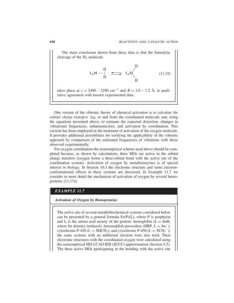
The main conclusion drawn from these data is that the homolyticcleavage of the H2 molecule
LnMLnM
H
HH
H(11.32)
takes place at ν = 2400 − 2100 cm−1 and R = 1.0 − 1.2 A, in quali-tative agreement with known experimental data.
One version of the vibronic theory of chemical activation is to calculate theorbital charge transfers �qi to and from the coordinated molecule and, usingthe equations presented above, to estimate the expected distortion, changes invibrational frequencies, anharmonicities, and activation by coordination. Thisversion has been employed in the treatment of activation of the oxygen molecule.It provides additional possibilities for verifying the applicability of the vibronicapproach by comparison of the estimated frequencies of vibrations with thoseobserved experimentally.
For oxygen coordination the semiempirical scheme used above should be com-pleted because, as shown by calculations, three MOs are active in the orbitalcharge transfers (oxygen forms a three-orbital bond with the active site of thecoordination system). Activation of oxygen by metalloenzymes is of specialinterest in biology. In Section 10.3 the electronic structure and some electron-conformational effects in these systems are discussed. In Example 11.7 weconsider in more detail the mechanism of activation of oxygen by several hemo-proteins [11.17a].
EXAMPLE 11.7
Activation of Oxygen by Hemoproteins
The active site of several metallobiochemical systems considered belowcan be presented by a general formula Fe(P)(L), where P is porphyrinand L is the amino acid moiety of the protein: hemoglobin (L = ImH,where Im denotes imidazol), horseraddish peroxidase (HRP, L = Im−),cytochrome P-420 (L = SHCH3), and cytochrome P-450 (L = SCH3
−);the same systems with an additional electron were also tried. Theirelectronic structures with the coordinated oxygen were calculated usingthe semiempirical MO LCAO IEH (SCCC) approximation (Section 5.5).The three active MOs participating in the bonding with the active site
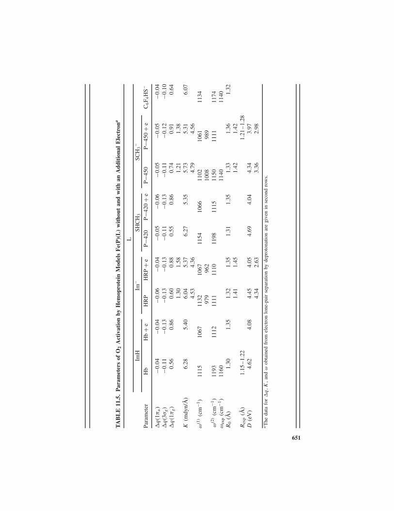
TA
BL
E11
.5.
Par
amet
ers
ofO
2A
ctiv
atio
nby
Hem
opro
tein
Mod
els
Fe(
P)(
L)
wit
hout
and
wit
han
Add
itio
nal
Ele
ctro
na
L
ImH
Im−
SHC
H3
SCH
3−
Para
met
erH
bH
b+
eH
RP
HR
P+
eP−
420
P−42
0+
eP−4
50P−
450
+e
C6F 4
HS−
�q
(1π
u)
−0.0
4−0
.04
−0.0
6−0
.04
−0.0
5−0
.06
−0.0
5−0
.05
−0.0
4�
q(3
σg)
−0.1
1−0
.13
−0.1
3−0
.13
−0.1
1−0
.13
−0.1
1−0
.12
−0.1
0�
q(1
πg)
0.56
0.86
0.60
0.88
0.55
0.86
0.74
0.91
0.64
1.30
1.58
1.21
1.38
K(m
dyn/
A)
6.28
5.40
6.04
5.37
6.27
5.35
5.73
5.31
6.07
4.53
4.36
4.79
4.56
ω(1
)(c
m−1
)11
1510
6711
3210
6711
5410
6611
0210
6111
3497
996
210
0898
9ω
(2)
(cm
−1)
1193
1112
1111
1110
1198
1115
1150
1111
1174
ωex
p(c
m−1
)11
6011
4011
40R
0(A
)1.
301.
351.
321.
351.
311.
351.
331.
361.
321.
411.
451.
421.
42R
exp
(A)
1.15
–1.
221.
21–
1.28
D(e
V)
4.62
4.08
4.45
4.05
4.69
4.04
4.34
3.97
4.34
2.63
3.36
2.98
aT
heda
tafo
r�
q,K
,an
dω
obta
ined
from
elec
tron
lone
-pai
rse
para
tion
byde
prot
onat
ion
are
give
nin
seco
ndro
ws.
651

652 REACTIVITY AND CATALYTIC ACTION
of the enzyme are 3σg, 1πu, and 1π∗g . The corresponding three orbital
vibronic constants f (i), force constant k(i) and anharmonicity γ (i) coef-ficients were calculated by Eqs. (11.2) using spectroscopic data foroxygen and its ions [11.17a]. The constants were calculated for thecoordination of the superoxide ion O2
− which is more appropriate tothe state of coordinated oxygen in hemoproteins. Unlike the examplesabove, the Morse potential instead of the cubic polynomials (11.7) wasemployed in calculation of the vibrational frequencies and interatomicdistances in the coordinated state. The 3σg and 1πu MOs of oxygen arebonding, while 1π∗
g is antibonding, but with respect to the superoxideion their contribution to the force constant has an opposite sign.
Some results for the calculated charge transfers, interatomic dis-tances, vibrational frequencies, and activation of coordinated oxygenare illustrated in Table 11.5. It is seen that the activation is due mainlyto the contribution of the charge transfer �q(1π∗
g ) to the antibonding1π∗
g MO of oxygen, which in the case of cytochrome P−450 + e- is∼0.91, and in the approximation when the sulfur lone pair is separated(Section 10.3) it is even larger. However, the value of ∼1.4 electron inTable 11.5 is overestimated because of the use of the “frozen orbital”approximation.
The resulting activation of the O—O bond is significant; in the coor-dinated state D is almost half of the dissociation energy D0, but it isstill larger than the activation energies of the reaction of hydroxyla-tion by cytochrome P-450 (∼1 eV). One reason for this discrepancy isthat D0 in Eqs. (11.9) and (11.18) is not the dissociation energy, butthe activation energy in the corresponding associative reactions with-out catalyst participation, which is smaller than the dissociation energy(Fig. 11.7). The calculated frequencies of O2 stretching vibrations arein good agreement with the experimental data available.
Jahn–Teller- and Pseudo-Jahn–Teller-Induced Chemical Activation
The influence of the electronic rearrangement on the reactivity of a molecularsystem, discussed above in this section, is attributed to the occurrence of a dis-torting force F , the changes of the force constant �K , and anharmonicity �γ inthis rearrangement [Eq. (11.13)]. The change of the rising portion of the reactioncurve as a function of the reaction pathway and the consequent change of theactivation energy −�D = D0 − D are shown in Fig. 11.7. By comparison, onecan see that near the origin Q = 0 these changes are similar to those producedby the JT or PJT effects (Sections 7.3 and 7.4, Fig. 7.5). In the JTE (degenerateelectronic states) a nonzero force distorts the high-symmetry nuclear configura-tion in the direction of JT active coordinates Q; if the quadratic terms of vibronic

ELECTRONIC CONTROL OF CHEMICAL ACTIVATION VIA VIBRONIC COUPLING 653
interactions are taken into account, the force constant (APES curvature) K0 isalso changed. In the PJTE (mixing of the ground and excited electronic states bythe nuclear displacements), the force constant K0 changes as well.
If a JT system enters a chemical reaction, the behavior of its APES bothwithout and with the JTE as a function of the JT active coordinate Q [ε0(Q)
and ε(Q), respectively] follow exactly Eqs. (11.8) and (11.13), respectively, asillustrated in Fig. 11.7. This means that the JTE produces the same kind ofchemical activation −�D as a corresponding electronic rearrangement inducedby, say, a catalyst. The chemical activation −�D is determined here by the sameequation [Eq. (11.17)] with Q0 and �K = K − K0 taken from the JTE formulas(Section 7.3).
If the quadratic vibronic coupling terms in the JTE are neglected (linearvibronic coupling), then K = K0, γ = γ0, and expression (11.19) is simplified:
−�D = (12D0EJT )1/2 − 4EJT (11.33)
where EJT is the JT stabilization energy (Section 7.3). For instance, for a systemwith a double-degenerate electronic E term EJT = F 2/2K0 [see Eq. (7.41)] and
−�D = |F |(
6D0
K0
)1/2
− 2F 2
K0(11.34)
Calculation of the chemical activation −�D for a PJT system becomes morecomplicated since an additional important parameter emerges: the energy gap 2�
between the ground and excited states whose admixing produces the instabilityof the ground state of the reactant. Figure 11.10 shows the two reaction curves,without and with the PJTE in the direction of the reaction path Q. The curve
FIGURE 11.10. Cross section of APES along the reaction path Q without (1) and with(2) the strong pseudo-Jahn–Teller effect that mixes the states 1 and 3.

654 REACTIVITY AND CATALYTIC ACTION
modified by the PJTE differs from the JTE curve (Fig. 11.7) by the behavior nearthe origin Q = 0.
If the condition of the strong PJTE (7.71), K0 < F 2/�, holds, the ground stateis unstable at Q = 0 and the adiabatic potential curve (7.69) has two minima atthe points (7.72) with the curvature at the minima points given by Eq. (7.73).Factoring in the anharmonicity produced by the interacting reactants, we canpresent the reaction curve by adding a negative cubic anharmonicity term toEq. (7.69), which, unlike (11.8) or (11.13), should be of the sixth order to preservethe symmetry conditions (with regard to inversion of Q):
ε(Q) = 12K0Q
2 − (�2 + F 2Q2)1/2 − γQ6 (11.35)
This curve has not been studied in detail as yet. Approximately, by expansion ofthe square root, we get (cf. (7.66)):
ε(Q) = 1
2KQ2 + F 4
8�3− γQ6
K = K0 − F 2
�
(11.36)
and for the points of the minimum Q0 (stable reactants), and maximum QD
(activated complex), we have
Q0,D ={
F 4
24�3γ
[1 ±
(1 + 48γK�6
F 8
)]1/2}1/2
(11.37)
with the minus sign for Q0 and plus sign for QD . Note that, due to (7.67), K < 0,and hence for real roots of Eq. (11.37) the condition |48γK| < F 8/�6 must beobeyed. If this inequality is sufficiently strong, we have approximately
Q0 ≈√
2�
F
(1 − K0�
F 2
)1/2
(11.38)
QD ≈(
F 8 + 24K�6γ
12γ�3F 4
)1/2
(11.39)
By substituting the parameters (11.37) or (11.38) and (11.39) into (11.35), onecan estimate the activation energy modified by the PJTE
D = ε(QD) − ε(Q0) (11.40)
and the chemical activation −�D = D0 − D [with D0 after (11.9)].

ELECTRONIC CONTROL OF CHEMICAL ACTIVATION VIA VIBRONIC COUPLING 655
Thus the JT- and PJT-induced chemical activation (one of the particular casesof the TEST paradigm; Section 7.4) is similar to the effect of electronic rear-rangement under the influence of a catalyst as discussed above. However, alongwith this important similarity there are also essential differences between thetwo sources of chemical activation. First, they are concerned with the directionQ, in which the activation energy is lowered, that is, with the allowed mecha-nism of the reaction. In systems with the JT and PJT effects, this direction ispredetermined by the electronic structure of the molecule itself (by the JT andPJT active displacements), whereas in the case of catalyst influence the directionof chemical activation depends on the nature of the catalyst, on the electronicrearrangement it produces in the reagents. Therefore, different catalysts can, inprinciple, cause different dominating mechanisms. In particular, the catalyst canchange the mechanism of the reaction that takes place without the catalyst. On thecontrary, for vibronically induced reactions of free molecules the mechanism isknown a priori, and this allows us to predict the reaction course and its products.Example 11.8 illustrates this statement for Jahn–Teller-induced reactions.
EXAMPLE 11.8
Jahn–Teller-Induced Substitution Reactions in OctahedralComplexes with an E Term
Consider the reaction of substitution in, or monomolecular decomposi-tion of, an octahedral transition metal complex in an orbitally twofold-degenerate electronic E state [11.6, 11.29], for example, for bivalentcopper known to have a strong JTE. The APES of this system has threeequivalent minima, in each of which the octahedron is elongated alongthe tetragonal axis, with two ligands being farther away from the centralatom than the other four (Sections 7.3 and 9.2). In Qθ and Qε coordi-nates (Fig. 7.1) the distortion takes place along the Qθ direction; Qθ
is thus the coordinate along which the activation energy of the reactionis lowered (the system is chemically activated) as compared with otherdirections, ceteris paribus. As a result, the reaction should proceed inthe direction of the Qθ displacements, which cause the two axial ligandsto move away from (while the other four approach) the CA (Fig. 9.20).For the monomolecular reaction this implies dissociation of the lig-ands in the trans positions, while for the substitution reaction it meansthe formation of trans-substituted complexes. Visually, this conclusioncorresponds to the following picture; when elongated octahedrons areformed, in the pulsating motions during a specific lifetime (Section9.2), the two ligands in trans positions are more weakly bonded andreached more easily by the attacking reagents. Thermodynamic consid-erations (Section 9.3) also support the conclusion about the formationof trans-substituted complexes of E-term metals.

656 REACTIVITY AND CATALYTIC ACTION
This result is in complete agreement with the well-known empiri-cal data on the behavior of octahedral complexes of Cu(II) in solutionor gas phase. It is known that these complexes lose two ligands inthe trans position, forming square-planar structures, while substitutionreactions produce only trans-substituted complexes (except for biden-tate ligands, which can be cis-coordinated only). On the other hand, ifthe JTE in such a system is quenched (say, by the significant differ-ences between the ligands), the potential barrier essentially increasesand the reaction rate decreases. This conclusion also agrees with exper-imental data [11.30] showing the substitution reaction rate to decreaseabout 3000 times when passing from [Cu(H2O)6
2+] to [Cu(tren)H2O]2+(where tren = 2, 2′, 2′′-triaminotriethylamine). According to predictionsof the theory, similar effects are expected in octahedral complexes ofCr(II), Mn(III), Ag(II), . . . that have E ground terms (see also ProblemP11.10).
For nonoctahedral molecular configurations with E terms and for other termsthe expected vibronically induced mechanisms of reactions are different fromthat considered in Example 11.8 for octahedral Cu(II) complexes. They can bequalitatively determined from known JT and PJT distortions. There are othersuggested applications of the vibronic effects in determining the chemical reactionrate and mechanisms ([11.6, 11.31]).
11.3. DIRECT COMPUTATION OF ENERGY BARRIERSOF CHEMICAL REACTIONS
Methods of numerical computation of the electronic structure of coordinationcompounds involving computer and supercomputer calculations (Chapters 5 and6) allow one, in principle, to obtain the APES for any chemical reaction, includingcatalytic reactions, and to estimate the numerical value of the energy barrier(activation energy) of the reaction. Practically, the solution of this problem maybe very laborious and costly. However, the continuous improvement of methodsand algorithms, as well as computer power, makes it possible to solve increasinglycomplicated problems.
In this section we discuss several examples of numerical calculations of theAPES and consequent properties of chemical reactions with coordination com-pounds, including cases when the latter act as catalysts.
Substitution Reactions: The trans Effect
In Section 9.3, which is devoted to the mutual influence of ligands in coordina-tion compounds, the phenomena of trans and cis influences in stereochemistry
DIRECT COMPUTATION OF ENERGY BARRIERS OF CHEMICAL REACTIONS 657
problems are discussed. We emphasized the need to distinguish between the ther-modynamic aspect of the problem (trans influence), in which the mutual influenceis considered from the static (energetic) point of view, and the kinetic aspect(trans effect), in which the influence of mutual ligand positions on the reactionrate of substitution or decomposition reactions is discussed. In this section wediscuss mutual ligand effects —the influence of a given ligand on the energy bar-rier of the reactions of substitution (or cleavage) of another ligand in the transor cis position.
There is an obvious correlation between the mutual influence and mutual effectof ligands as they are defined above. For instance, as shown in Section 9.3, thetrans influence results in a weakening of the metal–ligand bond in the transposition to the influencing ligand. It is clear that the weaker bond is subject toeasier cleavage or substitution (see Example 11.8). Hence the trans influence alsopromotes the trans effect. On the other hand, for a bimolecular associative SN2reaction, the formation of the reaction barrier may be much stronger dependenton (and on more details of) the electronic structure of both reactants (especiallythe entering, leaving, and trans-directing ligands) than the stereochemistry of theinitial complex, where mainly one ligand is specified.
Square-planar complexes of Pt(II) were suggested first [11.32] and are beststudied (see the reviews in Refs. 11.33–11.36) as demonstrating the trans effectin the most explicit way. Usually the series of ligands arranged in decreasingtrans-effect power (the trans-effect series) is given as follows [11.37]:
C2H4, CO > CN > NO2− > SCN− > I− > Br− > Cl− > NH3 > OH− (11.41)
In Section 9.3, many examples are given (see Tables 9.8–9.11) and the roleof some major electronic features of the ligand and the metal in realizing thetrans influence is discussed. It is shown that the σ -donor properties of the ligandenhanced by its π-acceptor properties are most important in the trans influence.Basically, these ideas are also valid in the trans effect, with the distinction thatin the latter the π-acceptor properties are more important. The qualitative reasonfor this π effect was discussed first by Chatt et al. [11.38] and by Orgel [11.39]and is illustrated in Fig. 11.11.
If the ligand L in the square-planar complex of Pt(II) has the strongest π-acceptor properties (low-energy empty π orbitals), then there is a backdonationto this ligand from the dxz orbital of the metal M [which is occupied in the d8
configuration of Pt(II)]. This backdonation results in a significant rearrangementof the electron distribution in which the electron density along the trans bondM—A is decreased. In turn, this lowers the repulsion from the entering group inthe trans position, thus lowering the energy of the transition state of the reactionand hence the activation energy. Hence the trans influence, which weakens andelongates the M—A bond, also contributes to lowering the activation energy byfacilitating the approach of the attacking group and removal of the leaving group.Note that if the dxz orbital is not occupied, this π effect disappears.

658 REACTIVITY AND CATALYTIC ACTION
FIGURE 11.11. Illustration of the σ –π interaction in the trans effect: the π-acceptorproperties of the trans-influencing ligand L enhanced by its σ -donor properties lower theelectron density along the trans bond M—A, thus favoring the labilization and substitutionof the trans ligand A.
As discussed elsewhere in this book (Sections 6.3, 9.3, and 11.2), as a resultof σ -donor and π-acceptor effects the corresponding orbital charge transfers haveopposite signs, and hence their sum is smaller than each of them individually.Therefore, in the presence of strong π donation to the ligand its σ -donor propertyincreases, and vice versa; strong σ donation increases the π-acceptor ability. Thismutual enhancing of σ -donor and π-acceptor properties is important in under-standing both the trans influence (Section 9.3) and trans effect. For instance,H− has empty π states (2pz), but in the free ion they are rather high in energyand hence H− is a poor π acceptor. However, in the coordinated states withstrong σ donation, its 2pz orbital energy lowers significantly, and H− becomesa better π acceptor.
It was also shown [11.40] that the competition of the ligands in the σ donationto the metal results in a characteristic cis effect —the influence on the reactionrate of ligand substitution in the cis position. The cis effect is opposite to thetrans effect; the larger the trans effect of a given ligand, the smaller its cis effect .This means that the reaction rate for the substitution of A is determined by (1) thetrans-effect power of the trans ligand L and, (2) the cis-effect power (oppositeto trans-effect power) in the cis positions of L and A. The higher the trans effectof the trans ligand and the lower the trans effect of the cis ligands, the higherthe reaction rate for the given ligand.
These general qualitative considerations were confirmed by direct numericalcalculations of transition states and energy barriers of substitution reactions withsome square-planar Pt(II) and Rh(I) complexes [11.41]. To reveal the trans effectin detail, four reaction systems were computed; for each of them the reactions ofsubstitution of two ligands in trans positions to two other ligands were studiedto compare their trans effects:

DIRECT COMPUTATION OF ENERGY BARRIERS OF CHEMICAL REACTIONS 659
cis − Rh(CO)H(NH3)2 + NH3 comparing CO and H− (11.42)
cis − PtH(Cl)(NH3)2 + NH3 comparing H− and Cl− (11.43)
cis − Pt(CH3)Cl(NH3)2 + NH3 comparing CH3− and Cl− (11.44)
cis − Rh(Cl)NH3(H2O)2 + H2O comparing Cl− and NH3 (11.45)
In all these reactions the entering and leaving groups are identical [NH3 for thefirst three cases and H2O for (11.45)]. This simplifies the calculations since itallows one to use additional symmetry considerations. In particular, the identicalentering and leaving groups should occupy equivalent positions, provided thatthere are no additional local minima (intermediates) on the reaction curve. Forsimplicity, all the groups are chosen neutral.
The computation scheme is as follows. For each substitution reaction thegeometry (bond lengths and angles) of the five-coordinated complex (associativeSN2 reaction) is optimized, yielding the energy of the transition state. With respectto the energies of the free reactants, this gives the activation energy. In all eightreactions (11.42)–(11.45), the transition state is a trigonal bipyramid with a mirrorplane for the two equivalent groups, entering and leaving. Then, allowing one ofthese groups to move away and calculating the optimized geometry and energy forseveral fixed positions of this leaving group, one obtains the reaction curve alongthe reaction coordinate. This curve is illustrated in Fig. 11.12 for the reaction
FIGURE 11.12. APES along the reaction coordinate for the substitution reaction cis-PtHCl(NH3)2 + NH3 with H− as a trans-directing ligand. (After Lin and Hall [11.41].)

660 REACTIVITY AND CATALYTIC ACTION
FIGURE 11.13. Optimized geometries for several fixed positions of the entering NH3
group in reaction (11.43) with H− as the trans-directing ligand.
cis-PtHCl (NH3)2 + NH3 with the substitution trans to H. The optimized ligandpositions along the reaction path are shown in Fig. 11.13.
All the calculations were carried out by the ab initio MO LCAO RHF(restricted Hartree–Fock) method with effective core potentials (Sections 5.3and 5.4) (calculation details are described well by Lin and Hall [11.41]). Thevalidity of the results, especially the role of electron correlations, was examinedby comparison with more sophisticated valence approaches. Total energies andactivation energy differences (relative trans effects) are given in Table 11.6.
We begin the discussion of these results with Fig. 11.13 showing the optimizedgeometries for several fixed positions of the entering group NH3 in the reaction

DIRECT COMPUTATION OF ENERGY BARRIERS OF CHEMICAL REACTIONS 661
TABLE 11.6. Total Energies of Transition States and Activation EnergyDifferences for Different trans-Directing Ligands (Relative trans Effect) inSubstitution Reactions (11.42)–(11.45)
Total Energy ActivationTrans-Directing of Transition Energy Difference
System Ligand State (au) (kcal/mol)
Rh(CO)H(NH3)3 CO −78.0154 10.92H− −78.0239
PtHCl(NH3)3 H− −75.7388 1.57Cl− −75.7363
Pt(CH3)Cl(NH3)3 CH3− −83.3640 0.38
Cl− −82.3634RhCl(NH3)(H2O)3 Cl− −97.8882 7.28
NH3 −97.8766
Source: Lin and Hall [11.41].
(11.43) with H− as the trans-directing ligand. To understand the origin of thesegeometries, let us also employ the qualitative σ MO energy-level scheme forthe initial square-planar 16-electron complex M(d8)L4 shown in Fig. 11.14. It isseen that the LUMO is the pure pz orbital of M, which is perpendicular to theplane of the complex, while the three (dxy, dxz, dyz) orbitals form three occupiedlone pairs. When the π bonding is taken into account, these lone pairs form thecorresponding MOs that have asymmetric distribution shifted toward the mosttrans-directing ligand (Fig. 11.11).
At large distances R = 3.2 A (Fig. 11.13A), when there is no significant orbitaloverlap and bonding, the entering group NH3 forms an angle α = 78.5◦ with theplane; it is narrower than 90◦ because of the repulsion from the corresponding dε
lone pair, which has the asymmetric distribution, mentioned above (Fig. 11.11).At smaller distances the NH3 lone pair overlaps with the empty pz orbital to forma square-pyramidal structure and the angle α increases (Fig. 11.13, B and C). Atequilibrium distances (R = 2.73 A) the optimized transition state is reached thathas a pseudo-trigonal-bipyramidal structure (Fig. 11.13D); here a compromisebetween the repulsion of the two NH3 ligands, their repulsion from the dxz
lone pair, and bonding to the rehybridized p–d metal orbitals (including pz) isreached.
The less the repulsion from the lone pairs (directly dependent on theπ-acceptor properties of the trans-directing ligand) and the weaker themetal-leaving and metal-entering bonds [dependent on the σ -donor propertiesof the trans-directing ligand, Section 9.3, Eq. (9.30)], the lower the energy ofthe transition state and hence the activation energy. These features are effectivewhen the metal M has occupied dε orbitals and the latter have a sufficientdiffusiveness to overlap strongly with (and to be easily shifted to) the ligands.Second- and third-row d8 transition metals are good examples. Thus directnumerical calculations confirm the preceding qualitative statements: The trans

662 REACTIVITY AND CATALYTIC ACTION
FIGURE 11.14. Schematic presentation of the σ MO energy levels of a 16-electronsquare-planar d8 transition metal complex ML4..
effect is produced by an appropriate combination of π-acceptor and σ -donorproperties of the trans-directing ligand and occupied diffuse dε orbitals ofthe central atom . Numerical data of Table 11.9 show that among the ligandsconsidered, the trans effect follows the series CO > H− > CH3
− > Cl−, inagreement with the experimental order.
Lin and Hall [11.41] elucidate many other details of the trans-effect mecha-nism. In particular, they show that the monomolecular mechanism of substitutionreactions (via dissociation) have an activation energy that is considerably higherthan that in the associative mechanism.
Ligand Coupling and Cleavage Processes
Transition metal systems are often involved in chemical transformations as cat-alysts. In principle, catalytic reactions are similar to noncatalytic reactions withthe distinction that in the former the yield of the reaction leaves one of thereactants unchanged. In Sections 6.3 and 11.2, the specific features of transi-tion metals important to catalytic action are emphasized; because of the actived-electron configurations, transition metals and their complexes form multiorbitalbonds with ligands, with the effect of strong activation of the latter .

DIRECT COMPUTATION OF ENERGY BARRIERS OF CHEMICAL REACTIONS 663
Another important feature is that, owing to high coordination numbers, coor-dination compounds may serve as a center of “organization” of the reactantspromoting specific mechanisms of the reaction. This “organizational” aspect ofcoordination is of special importance in supramolecular chemistry , where thecoordination system, via recognition, orientation, and termination , serves as acenter of self-organization, self-assembly, and templating [11.42, 11.43].
A relatively simple example of catalytic action of coordination compounds isprovided by the bonding of two coordinated carbon ligands CR2 in cis positionsforming an olefin C2R4, and the inverse process of cleavage of a coordinatedolefin into a bis-carbene complex:
R
R
R
M
C
C
R
RM
C
R
R
RC(11.46)
The first attempt to model this reaction was made for the “naked metal” M = Wand R = H [11.44]. Figure 11.15 illustrates the MO energy-level diagram as afunction of the angle between the two carbon ligands obtained by the semiem-pirical extended Huckel method (Section 5.5). It is seen that for a metal M withmore than two electrons (in W they are six), the least-motion process of directbonding of two methylene groups CH2 to form C2H4 is forbidden by symmetryconsiderations (Section 11.1), since it involves the highly excited state 2b2 ofC2H4.
A more complete analysis, using the same approach and the same method ofcalculation, was carried out for the reactions [11.45]
(CO)4Cr(CH2)2 → (CO)4Cr(C2H4) (11.47)
(CO)4Cr(CD2)2 → (CO)4Cr(C2D4) (11.48)
where D is a π-donor substituent (D = NR2).For the reaction (11.47), the MO energy-level diagram [11.45] shows that, as
compared with the unligated metal (Fig. 11.15), the ordering of the important MOlevels under the influence of the four π-acceptor CO groups changes significantly,and the 2b2 MO is no longer involved in the reaction. Instead, the 1b2 level in theolefin side is pushed up and unoccupied, and hence the reaction of direct least-motion coupling is again formally forbidden. This means that somewhat lesssymmetric pathways, although formally allowed by symmetry considerations,may still encounter energy barriers.
The qualitative MO energy-level diagrams give no definite information aboutthe relative thermodynamic stability of the two systems and the height of the

664 REACTIVITY AND CATALYTIC ACTION
FIGURE 11.15. MO energy-level correlation diagram for a C2v least-motion cou-pling/decoupling of two methylene groups coordinated to a unligated metal center. Sym-metries of the AOs that form the corresponding MOs and the d2 configuration limit arealso shown. (After Hoffmann et al. [11.44, 11.45].)
energy barrier between them. To answer these questions, calculations of thepotential energy surface for the least-motion coupling (uncoupling) of the twomethyl groups in reaction (11.47) were carried out [11.45]. Two coordinates, theangles θ (between the two M—C bonds, Fig. 11.16) and � (between the CH2
plane and the M—C bond) were chosen to describe the reaction pathway. Theirvariation with the fixed position of the Cr(CO)4 group results in the potentialenergy surface presented schematically in Fig. 11.17. The surface has two min-ima for the olefin and bis-carbene complexes, respectively. Interestingly, in thismodel the olefin complex, which is a 16-electron system, is more stable than the18-electron bis-carbene complex; the allowance for a more relaxed configuration

DIRECT COMPUTATION OF ENERGY BARRIERS OF CHEMICAL REACTIONS 665
FIGURE 11.16. The angles θ and � chosen to describe the least-motion convergenceof two CH2 groups and their planes bending in the reaction (11.47). Instead of θ , theinteratomic rCC distance can be equally useful. (After Hoffmann [11.45].)
FIGURE 11.17. APES of the reaction (11.47) as a function of angles θ and � characteriz-ing the two methyl group least-motion convergence and their planes bending (Fig. 11.16).Contour lines at 0.1 eV separation. (From Hoffmann [11.45].)

666 REACTIVITY AND CATALYTIC ACTION
with optimization of the CO ligand positions is expected to lower the energy ofthe olefin complex. The energy barrier between these two minima is rather low,about 10 kcal/mol, and will be probably even lower for a less symmetric reactionpathway.
With good π-donor substituents in the methyl groups CD2, the situationchanges drastically. The experimental data show that in this instance the bis-carbene d6 complexes M(CO)4(CD2)2 are stable compounds and can be obtainedfrom the corresponding olefin. The calculations using the approach describedabove confirm these results and reveal their origin. The corresponding APES in(θ,�) coordinates for
C
D
D
C
NH
HN
=
is illustrated in Fig. 11.18. It is seen that here there is only one minimum forthe bis-carbene complex, and no minimum for the olefin complex. The MOenergy-level diagram [11.45] shows that the reaction under consideration issymmetry-allowed and may proceed without energy barrier, as the olefin complexis thermodynamically less stable (all the MO energy levels are lower in the bis-carbene complex). The reason for this effect can be revealed from the analysisof the MO energy-level reordering produced by the donor D substitution.
CO Reductive Hydrogenation and Carbonyl Insertion Reactions
Insertion reactions of the type
R L
MAn
L
MAnR→ (11.49)
where R is an unsaturated ligand and M—L is a metal–hydrogen or ametal–carbon bond, are most important in modern organometallic chemistry asthe key processes in many catalytic cycles. In this subsection we consider theexamples of CO insertion into M—H and M—CH3 bonds and a related reactionof coordinated CO hydrogenation [11.46, 11.47]. The next subsection is devotedto olefin insertion reactions.
Homogeneously catalyzed carbon monoxide hydrogenation underlies manyprocesses, including conversion of the CO/H2 mixture into liquid fuels and pro-duction of methanol, ethanol, ethylene glycol, and other compounds. The processcan be presented as either a nucleophilic addition of a hydride ion

DIRECT COMPUTATION OF ENERGY BARRIERS OF CHEMICAL REACTIONS 667
FIGURE 11.18. APES for the reaction (11.48). The coordinates θ and � (or rCC) aregiven in Fig. 11.16. (After Hoffmann [11.45].)
LnM LnMCO H−+ C
H
O−
→ (11.50)
or an insertion of a carbonyl ligand into the metal–hydride bond:
LnM
H
LnMCO C
O
H
−L
+LLn + 1M C
O
H
(11.51)
The two reactions (11.50) and (11.51), despite an apparent similarity, aresignificantly different; are many examples of the first reaction are known, whereasexamples of the second type, (11.51), are generally lacking, at least when resulting

668 REACTIVITY AND CATALYTIC ACTION
in a monohaptoformyl ligand. The hydride affinity of coordinated carbonyls islarge (ranging from 45 to 55 kcal/mol) as compared with that of bare carbonmonoxide (a few kcal/mol only), and this indicates the significant activation ofthe CO molecule by coordination to transition metals (Section 11.2).
To reveal the reaction mechanism, calculations of the APES in the spaceof a possible reaction pathway for prototype reactions have been performed[11.46]. The calculations carried out in the ab initio SCF-MO-LCAO approx-imation (Section 5.3) with extended basis sets and other computational detailsare discussed by Dedieu and Nakamura [11.46]. The role of electron correlationeffects was also elucidated by means of additional CI calculations (Section 5.3).
For the hydrogenation reaction, the reaction of addition of H− to Fe(CO)5 hasbeen considered:
H− + Fe(CO)5 → Fe(CO)4(CHO)− (11.52)
The approach of the hydride is restricted by the plane containing two axial ligandsand one equatorial ligand. The numerical results are illustrated in Fig. 11.19, andthe optimized geometry is shown in Fig. 11.20. In the geometry calculations theaxial Fe—C—O angle is allowed to relax, while the Fe—C and C—O distancesare kept fixed at 1.81 and 1.22 A, respectively.
Figure 11.19 shows that the reactions are highly exothermic (∼52 kcal/mol)and proceed without any energy barrier. This is in agreement with the correspond-ing gas-phase studies [11.48]. The calculation details also explain the origin ofthe high affinity of the activated CO ligand for the H− ion and the role of themetal dz2 orbital in this process [11.46].
For the CO ligand insertion reaction (11.49), the prototype example is takenas follows:
HMn(CO)5 → Mn(CO4)(CHO) (11.53)
In principle, there are two main pathways for this reaction to proceed: (1)proper insertion of the CO molecule into the Mn—H bond or (2) migration ofthe hydrogen atom to the CO ligand to form the CHO ligand. To reveal the trueprocess, a two-dimensional APES as a function of two critical angles, α and β,has been calculated [11.46]. The two angles are chosen as shown in Fig. 11.21,while the two out-of-plane (perpendicular to the reaction plane) carbonyl ligandsare kept frozen; the Mn—C and C—O bond lengths of the nonreacting in-planeCO ligands are also kept fixed at their experimental values. For each point of thesurface (α, β), the Mn—H bond length (d), the angles γ and δ, and the C—Obond length were successively optimized, and then the Mn—C bond length (R)was optimized for representative points of the minimum-energy path.
The results are illustrated in Fig. 11.22, and the successive geometries of thesystem along the resulting reaction path are given in Fig. 11.23. It is seen that

DIRECT COMPUTATION OF ENERGY BARRIERS OF CHEMICAL REACTIONS 669
FIGURE 11.19. Contour lines of the APES for the approach of the hydride ion (energiesin kcal/mol with respect to separated reactants). The inner contour is −52 kcal/mol. (AfterHoffmann [11.45].)
FIGURE 11.20. The optimized geometry of the hydrogenated system Fe(CO)4(CHO)−.

670 REACTIVITY AND CATALYTIC ACTION
FIGURE 11.21. Variation coordinates for the CO ligand insertion reaction (11.53).
the process is best described as a hydride migration and not CO insertion inagreement with experimental data and other theoretical investigations.
Figure 11.23 shows that the geometry of the CO groups remains virtuallyunchanged during the reaction. The geometry of the transition state D is nearthat of a five-coordinated formyl intermediate F . The energy profile as a functionof the H—Mn—C angle η for the configurations from A to F of Fig. 11.23 isshown in Fig. 11.24. In the SCF approximation the energy barrier of the reac-tions is about 15 kcal/mol with a small difference between D and F (about4 kcal/mol). However, CI calculations with electron correlation effects carriedout for the three key structures A, D, and F show a large increase in the reac-tion barrier of the forward reaction and its decrease (almost to zero) for theinverse reaction (Fig. 11.24). Analysis of computational details [11.46] showsthe reason for this result to be the inadequate description of the difference inthe π backdonation to CO and CHO without CI. This feature is also inherentin other processes in which similar ligand changes occur. For the whole pro-cess HMn(CO)5 + CO → Mn(CO)5CHO in which the number of CO ligands isnot changed, the calculated endothermicity 3.7 kcal/mol roughly agrees with theexperimental value of 5 kcal/mol.
Thus the failure to observe CO insertion into a metal hydride bond resulting ina monohaptoformyl ligand is well accounted for by the high energy barrier andthe close proximity of the transition state with the five-coordinated intermediate.
For a similar reaction of CO ligand insertion into a M—CH3 bond
→CH3
CH3
PH3
M H
C
O
PH3
M H
C
O
(11.54)
with M = Pd, Pt, calculations were carried out [11.47] for electronic structure,energy, and geometry of the initial complex, activated state, and the product of the

DIRECT COMPUTATION OF ENERGY BARRIERS OF CHEMICAL REACTIONS 671
FIGURE 11.22. Contour lines of the APES for the reaction (11.53) as a function of theangles α and β specified in Fig. 11.21. The distance R = 1.885 A is kept constant andthe energies are read off the point α = β = 0. (From Dedieu and Nakamura [11.46].)

672 REACTIVITY AND CATALYTIC ACTION
FIGURE 11.23. In-plane geometry changes along the reaction path of the hydride migra-tion in the HMn(CO)5 system (the two CO ligands perpendicular to the plane are notshown). (After Dedieu and Nakamura [11.46]).
reaction. The authors use the ab initio SCF MO LCAO restricted Hartree–Fock(RHF) approximation with gradient technique for geometry optimization andperturbation theory (MP2) for electron correlation effects (Section 5.3), as wellas relativistic effective core potentials for the metal atoms (Section 5.4).
The optimized geometries are illustrated in Fig. 11.25, while relative energiesare given in Table 11.7.
It is seen that, similar to the previous case of CO insertion into the M—H bond,where, in fact, there is no insertion but H migration, there is no CO insertioninto the M—CH3 bond, either; the reaction proceeds as a CH3 migration towardthe CO ligand in accordance with experimental data. The energy of a similartransition state with CO migration instead of CH3 [a configuration in whichthe angles (CO)—Pd—(H) and (CH3)—Pd—(PH3) of the true transition state inFig. 11.25 are exchanged] is about 7 kcal/mol higher than the true transition state.
The reason for this reaction pathway is in the strong repulsion of the carbonyllone pair from the occupied dxy orbital of the metal in the case of CO migration(Fig. 11.26a). This repulsion is significantly lower when the CH3 group migrates(Fig. 11.26b), due to the lower electron density in the hybridized sp3 orbitalpointed toward the lobe of the metal dxy orbital (approximately one electroninstead of two electrons in the CO lone pair) and the longer distance M—CH3.

DIRECT COMPUTATION OF ENERGY BARRIERS OF CHEMICAL REACTIONS 673
FIGURE 11.24. SCF and CI calculated energy profiles for the hydride migration process(Fig. 11.23) as a function of the H—Mn—C angle η.
FIGURE 11.25. Optimized geometries (in angstroms and degrees) of M(CH3)H(CO)PH3
and M(COCH3)H(PH3) (thick solid lines), M = Pd, Pt and the transition states (dashedlines) for the CO insertion (CH3 migration) and inverse reaction. (After Koga andMorokuma [11.47].)

674 REACTIVITY AND CATALYTIC ACTION
TABLE 11.7. Relative Energies (in kcal/mol) of the Transition States and Productsof Reaction M(CH3)H(CO)(PH3) → M(COCH3)H(PH3), with M = Pd, PtCalculated without (RHF) and with (MP2) Electron Correlation Effects
M Method Reactant Transition State Product
Pd RHF 0.0 25.8 19.1MP2 0.0 13.5 8.8
Pt RHF 0.0 31.3 23.0MP2 0.0 21.8 17.6
Source: Koga and Morokuma [11.47].
FIGURE 11.26. Interaction of two electrons of the CO lone pair and one electron of theCH3 sp3 orbital with the metal occupied dxy orbital in the CO migration (a) and in thetrue transition state of CH3 migration (b).
Although the structural changes in the preceding two reactions with Pdand Pt are almost the same, the energetics is quite different (Table 11.7); theactivation energy in the Pt complex is considerably higher than in Pd (at theMP2 levels 21.8 and 13.5 kcal/mol, respectively). This is due to the differencesin the M—CH3 and M—CO bond energies, which are, respectively, higher by7 and 11 kcal/mol in the Pt complex than in the Pd one, while the Pt—COCH3
bond is stronger by 9 kcal/mol than Pd—COCH3 bond. Therefore, the Pdreaction is more endothermic by (7 + 11 − 9) = 9 kcal/mol, and hence it has ahigher energy barrier.
The reaction was also studied for CH3-substituted ligands [11.47]. Someresults for the energetics of these reactions obtained for the fixed ligand geome-tries (Fig. 11.25) are given in Table 11.8.
Olefin Insertion Reactions
Olefin insertion reactions are of great importance in organometallic chemistryand chemical industry as basic models of the corresponding polymerization
DIRECT COMPUTATION OF ENERGY BARRIERS OF CHEMICAL REACTIONS 675
TABLE 11.8. Relative Energies (in kcal/mol) for the CO Insertion (R Migration)Reaction Pd(R)H(CO)(PH3) → Pd(COR)H(PH3)
R Reactant Transition State Product
CHF2 0.0 40.9 31.2C2H5 0.0 23.1 14.6
processes. Formally, olefin insertion is similar to the CO insertion consideredabove. For ethylene and its derivatives CX2 CH2 insertion into the M—H bond(and inversely, β elimination), the following four reactions were investigated[11.47]:
H
CX2
H
M PH3
CH2
H
H
M PH3
CH2CX2
(11.55)
M = Ni, X = H (11.56)
M = Pd, X = H (11.57)
M = Pt, X = H (11.58)
M = Pd, X = F (11.59)
The method of numerical computation is the same RHF method with theMP2 corrections mentioned above for the CO insertion reactions (for details, seethe paper by Koga and Morokuma [11.47]). This method was used to calculatethe optimized geometries and energies of the transition states and products of thereaction. The results are illustrated in Table 11.9 and Fig. 11.27. It is seen thatthe reaction proceeds as a hydrogen migration via a four-center transition state;its optimized geometry is shown for the Pt reaction (11.58).
For other reactions the transition state is similar, with the distinction that forNi and Pd the transition state is achieved much earlier with smaller distortionsof the M—H and C C bonds (Ni produces smaller distortions than does Pd)and corresponding structural differences in the products (see below). This is alsoseen from the energy profile of the reaction given by the energies in Table 11.9;the activation barrier is much lower for the Ni reaction (11.56) and increasesfor similar reactions (11.57) and (11.58) with Pd and Pt. On the other hand, thereaction for the Ni complex is also most exothermic.
These effects are due, first, to the strength of the M—(C2H4) bond, whichis very weak for Ni and increases for Pd and Pt. Therefore, the Pt–ethylenecomplex is more stable than the ethyl complex. The stability of the ethyl complexincreases in the order Pt < Pd < Ni, while the barrier height for the migrationreaction decreases in the order Pt > Pd > Ni. In general, the metal-ethylene bondsare relatively weak indicating a strong trans influence of the hydride ligand.

FIG
UR
E11
.27.
Opt
imiz
edge
omet
ries
(dis
tanc
esin
angs
trom
san
dan
gles
inde
gree
s)of
ethy
-le
nean
det
hyl
com
plex
esan
dth
etr
ansi
tion
stat
eof
the
reac
tion
Pt(C
H2= C
H2)(
H) 2
PH3
→Pt
(CH
3—
CH
2)(
H)P
H3
(for
sim
plic
ity,s
ome
ofC
—H
bond
leng
ths
and
angl
esar
eno
tind
icat
ed;
see
Kog
aan
dM
orok
uma
[11.
47])
.
676
DIRECT COMPUTATION OF ENERGY BARRIERS OF CHEMICAL REACTIONS 677
TABLE 11.9. Relative Energies of the Reaction M(H)2(CH2CX2)(PH3) →M(CH2CHX2)(H)(PH3) (in kcal/mol)
M X Ethylene Complex Transition State Ethyl Complex
Pd H 0.0 8.0 −3.00.0 5.1a 3.0a
Pd F 0.0 7.3 −11.1Ni H 0.0 0.6 −31.5Pt H 0.0 12.5 4.2aCalculated including correlation effects in the MP2 approximation with RHF geometries.
TABLE 11.10. Comparison of Activation Energies of β-Elimination ReactionsM(CH2CHX2)(H)(PH3) → M(H)2(CH2CX2)PH3 with a Qualitative Estimate ofInverse and Backdonative Interaction
M X Activation Energy Inverse Interaction Backdonation
Pd H 11.0 Excellent GoodF 18.4 Fair Good
Ni H 32.1 Good PoorPt H 8.3 Good Excellent
Source: Koga and Morokuma [11.47].
As for the inverse reaction of β elimination, its activation energy dependsmainly on two effects: (1) the remaining interaction of the migrating hydrogenHβ with the metal atom M via σ donation from the CHβ bonding orbital tothe empty d + p orbital of the free coordination place (the so-called inverseinteraction), and (2) the backdonation from the occupied metal dxy orbital to theantibonding σ ∗ orbital of CHβ that weakens the bonds in the latter. Calculations[11.47] show that the inverse interaction is stronger in the Pd reaction (11.57)and decreases toward Pt and Ni. The backdonation, on the contrary, is strongerin the Pt complex because of its more diffuse dxy orbital, and is very poor in Nifor similar reasons. The activation energy is thus a result of a combination ofthese two reasons, illustrated qualitatively in Table 11.10.
As mentioned above, insertion reactions underlie many catalytic processes. Asan illustration of this statement, the reaction of catalytic insertion of ethylene inthe M—CH3 bond in the Ziegler–Natta polymerization process is considered inExample 11.9.
EXAMPLE 11.9
Polymerization with Ziegler–Natta Catalysts
Ethylene insertion into the M—CH3 bond is the basic elementarystep in the well-known Ziegler–Natta catalytic ethylene polymerization

678 REACTIVITY AND CATALYTIC ACTION
process:
TiCl4 · Al(CH3)3 + C2H4 → TiCl4Al(CH3)2C3H7 (11.60)
Cossee [11.49] first considered this process as ethylene coordinationto Ti followed by a C2H4 insertion reaction into the Ti—CH3 bond in
FIGURE 11.28. The catalyst–ethylene complex in the Ziegler–Natta catalyticpolymerization of ethylene and the denotation of the atoms.
FIGURE 11.29. Geometric variation parameters describing the 12 steps inTable 11.11 in the pathway of the reaction (11.60). (After Novaro et al. [11.50].)

DIRECT COMPUTATION OF ENERGY BARRIERS OF CHEMICAL REACTIONS 679
the cis position, and involved ligand field and semiempirical MO LCAOconsiderations in support of this reaction mechanism. A more detailedcalculation of the energies along the reaction pathway and the acti-vation energy with a detailed analysis of the electronic origin of thephenomenon was carried out by Novaro et al. [11.50].
1 2
4 5 6
7 8 9
10 11 12
3
FIGURE 11.30. Molecular models for the 12 steps of the reaction (11.60)characterized in Table 11.11. (After Novaro et al. [11.50].)

FIG
UR
E11
.31.
Evo
lutio
nof
the
tota
len
ergy
(the
reac
tion
curv
e)in
the
Zie
gler
–N
atta
poly
-m
eriz
atio
npr
oces
s(1
1.60
)al
ong
agi
ven
path
way
spec
ified
byth
e12
step
sin
Tabl
e11
.11.
680

TA
BL
E11
.11.
Geo
met
ries
and
Tota
lE
nerg
ies
for
aSe
quen
ceof
Con
figur
atio
nsD
escr
ibin
gth
eP
athw
ayof
Rea
ctio
n(1
1.60
)a
Rea
ctio
nR
(Ti−
C4)
R(T
i−C
5)
R(T
i−C
3)
R(C
3−C
5)
αR
α0
αI
r�
E=
Ei−
E1
Step
(A)
(A)
(A)
(A)
(◦ )(◦ )
(◦ )(A
)(k
cal/m
ol)
17.
037.
032.
155.
5545
011
71.
337
02
5.04
5.04
2.15
3.58
450
117
1.33
7−0
.33
4.06
4.06
2.15
3.23
280
117
1.33
7−1
.94
3.08
3.08
2.15
2.71
138
115
1.38
3−4
.25
2.59
2.59
2.15
2.70
816
115
1.38
3−3
.06
2.40
2.43
2.15
2.69
019
114
1.40
6+5
.37
2.24
2.39
2.26
2.48
−2.3
2311
3.25
1.42
815
.08
2.18
2.49
2.37
2.31
−4.6
2811
2.49
1.45
110
.99
2.14
2.60
2.48
2.14
−6.9
3411
1.74
1.47
31.
110
2.12
42.
732.
591.
95−9
.240
.911
0.98
1.49
5−1
4.2
112.
126
2.88
2.65
1.75
−11.
547
.811
0.23
1.51
8−3
4.5
122.
153.
032.
811.
54−1
3.8
54.7
109.
471.
54−4
0.3
aT
heen
ergy
isre
adof
fth
efir
stst
epw
ithE
1=
−311
2.16
81au
.T
hege
omet
ric
para
met
ers
are
defin
edas
show
nin
Fig.
11.2
9;r
=R
(C4−
C5).
Sour
ce:
Nov
aro
etal
.[1
1.50
].
681

682 REACTIVITY AND CATALYTIC ACTION
A schematic representation of the catalyst–ethylene complex and thenotation of atoms is shown in Fig. 11.28. The reaction mechanism isassumed, in principle, to be similar to that suggested earlier by Cossee[11.49]; 12 steps, including ethylene bonding and CH3 migration, aretaken as the reaction pathway. Calculations were carried out by means ofthe ab initio all-electron SCF MO LCAO (RHF) approximation (Section5.3). The parameters for the 12 steps and the calculated energies aregiven in Table 11.11, while denotation of the corresponding angles isshown in Fig. 11.29. For each Ti—C2H4 distance, optimization of theother parameters is performed. A visual presentation of the reaction bymeans of molecular models is given in Fig. 11.30.
Figure 11.31 shows the evolution of the total energy of the system asa function of the reaction path presented by the 12 reaction steps men-tioned above. It is seen that at the beginning of the ethylene approach tothe complex the energy lowers slightly, due to the metal–ethylene bondformation with a bonding energy of more than 4 kcal/mol. At step 6 witha Ti—C2H4 distance of 2.4 A, the energy increases, and this increaseis attributed mainly to the ethylene’s π-bond breaking. The highestactivation of the C C bond is reached at step 7 [R(Ti—C4) = 2.24A, R(Ti—C5) = 2.39 A], after which the bonding to the CH3 groupincreases and the energy decreases; at step 8 the π bond finally breaks.These and many other details are seen clearly from the MO populationsand charge distribution discussed thoroughly by Novaro et al. [11.50].
Photochemical Reactions of Organometallics
From the computational perspective, photochemical reactions are more compli-cated because they involve excited states for which quantum-chemical calcula-tions are in general more difficult. On the other hand, photochemical reactions arerather widespread in chemistry. By way of examples demonstrating theoreticalpossibilities, the following reactions are considered [11.51]:
Fe(CO)5hν→ Fe(CO)4 + CO (11.61)
HCo(CO)4hν→ Co(CO)4 + H (11.62)
Mo(CO)5L + L′ hν→ Mo(CO)4LL′ + CO (11.63)
L = NH3, PMe3, C(OMe)H, C2H4
The calculations were carried out by the ab initio SCF MO LCAO methodwith CI (Section 5.3). For all these reactions the APES of the ground and excitedelectronic states as a function of the corresponding coordinate of the ligandelimination were calculated and analyzed. Strictly speaking, these curves are

DIRECT COMPUTATION OF ENERGY BARRIERS OF CHEMICAL REACTIONS 683
cross sections of the multidimensional APES, with some additional symmetryand bond lengths restrictions.
For the first reaction, (11.61), the reaction path of equatorial CO ligand elimi-nation is taken as shown in Fig. 11.32a maintaining C2v symmetry of the product.For the second reaction, (11.62), both the reactant and the product Co(CO)4
belong to C3v symmetry (in their ground states), and therefore the reaction coor-dinate is taken as shown in Fig. 11.32b.
The results of the computations for these two reactions are illustrated inFigs. 11.33 and 11.34. It is seen that in both cases there are excited states thatlead to the ligand elimination without any energy barrier. However, not all theexcited states evolve to the dissociation products in their ground states. A specialfeature of the two reactions is that their products have a triplet spin ground state,3B2 and 3A1 for reactions (11.61) and (11.62), respectively. This means that,since the ground states are singlets, only singlet–triplet excitation may lead todirect photolysis of the ligands shown above: 1A1 →3 E′ in CO photoeliminationfrom Fe(CO)5, and 1A1 →3 A1 in hydrogen elimination from HCo(CO)4.
These electronic singlet → triplet transitions are spin-forbidden (Section 8.1),and therefore they are difficult to perform experimentally, especially in the pres-ence of close-in-frequency, much more intensive singlet–singlet transitions (e.g.,1A′
1 →1 E′ in Fig. 11.33). Therefore, another mechanism of photolysis has beensuggested [11.51]. It is illustrated in Fig. 11.35; the reactant is photoexcited toa singlet state and then, by way of radiationless transition (via spin–orbital cou-pling and thermal effects), the corresponding triplet state is populated. From thelatter the molecule, according to Figs. 11.33 and 11.34, can dissociate to theproducts in the ground state without any energy barrier.
In fact, this mechanism of photolysis is valid (qualitatively) in many otherphotochemical reactions where homolysis of a σ bond takes place with the reac-tant in a singlet ground state and the products in a triplet state. Daniel andVeillard [11.51] list some examples, including dissociation of hydrogen from
FIGURE 11.32. The reaction pathway for CO elimination from Fe(CO)5 (a) and hydro-gen dissociation from HCo(CO)4 (b).

684 REACTIVITY AND CATALYTIC ACTION
FIGURE 11.33. Potential energy curves for the ground state and two excited states in thedissociation process Fe(CO)4 + CO under the C2v constraint. (From Daniel and Veillard[11.51].)
metal hydrides HMn(CO)5, HReCp2, HW(CO)3Cp, photochemical cleavage ofthe metal–carbon bond in RMn(CO)5 with R = CH3, C6H5, metal–silicon bondin R3SiCo(CO)4, R = Et, Ph, and metal–metal bond in Mn2(CO)10.
The photosubstitution reactions (11.63) proceeds via a primary photodissoci-ation of a CO ligand
M(CO)5L → M(CO)4L + CO (11.64)
and subsequent reaction of the unsaturated species M(CO)4L with L′:
M(CO)4L + L′ → M(CO)4LL′ (11.65)
One of the most important features of this photoreaction is its stereospecificity:its product, M(CO)4LL′, is a cis-disubstituted derivative. Therefore, one goal ofthe calculations [11.51] is to explain this characteristic cis-stereospecificity.
The photoelimination reaction (11.64) is more complicated than (11.61) or(11.62), and therefore the calculations have been restricted to a number of remark-able points of the potential energy surface. Figure 11.36 illustrates some resultsof such calculations showing the evolution of two important singlet states of thephotoexcitation in the reaction and subsequent transformations [the final prod-uct M(CO)4LL′, as a d6 hexacoordinated complex, is assumed to have a singletground state].
The mechanism of the photoreaction of ligand substitution (11.63)emerging from these computations is as follows. By photoexcitation of the

DIRECT COMPUTATION OF ENERGY BARRIERS OF CHEMICAL REACTIONS 685
FIGURE 11.34. Potential energy curves (ground and excited) for dissociation of theCo—H bond in HCo(CO)4 under C3v constraint. (From Daniel and Veillard [11.51].)
complex M(CO)5L, the reaction of CO elimination takes place, resulting in asquare-pyramidal structure with C4v symmetry and the axial ligand eliminated(Fig. 11.36a), or a pseudo-square-pyramidal structure if the equatorial ligand iseliminated (Fig. 11.36b).
In the axial elimination, the excited state in the C4v configuration has nominimum energy (Fig. 36a); by an internal rotation (pseudorotation, or Berryrotation, Section 9.2) via an intermediate trigonal-bipyramidal structure, it trans-forms itself to the pseudo-square-pyramidal structure shown in the right-handside of Fig. 11.36a. From this metastable state, a radiationless transition to theground state takes place. In the case of equatorial ligand elimination the sys-tem relaxes to this minimum-energy pseudo-square-pyramidal structure directly,without additional transformations (Fig. 11.36b). It is seen that, beginning withthis configuration, the subsequent reaction (11.64) proceeds as an addition ofL′ to the only free coordination place of the photoinduced complex, resulting ina cis-bisubstituted system M(CO)4LL′.
For another example of ab initio calculated photochemical reaction, the pho-tochemical cleavage of the metal–hydrogen bond in aluminum porphyrins, seethe article by Rohmer and Veillard [11.52].

686 REACTIVITY AND CATALYTIC ACTION
FIGURE 11.35. Mechanism of photochemical dissociation starting from a singlet groundstate to triplet state products.
FIGURE 11.36. State correlation diagram for the reaction of photoelimination of the axial(a) or equatorial (b) carbonyl ligand from Mo(CO)5L and consequent internal rotation(the eliminated ligand is not shown in the products). The straight-line arrows show theevolution of the excited state to the configuration of minimum energy, while the wavy-linearrows show the radiationless transitions to the ground state.
SUMMARY NOTES
1. Chemical reactivity —the ability of a system to react with another molecu-lar system—can be measured by the relative rate of chemical transforma-tion in the elementary act of the reaction (the full rate of reaction dependsalso on kinetic factors).

QUESTIONS AND PROBLEMS 687
2. The inverse of activation energy of the reaction may serve as a measure ofrelative reactivity of molecular systems in reactions with the same reagent.There is also an approximate relationship between the activation energy andthe heat of the reaction given by the Marcus equation; in similar reactionsthe activation energy decreases with the heat release in exothermic reactionsand increases in endothermic reactions.
3. In the first approximation to the problem of electronic origin of reactivitythe idea of the essential role of frontier orbitals, HOMO and LUMO, isemployed. Approximate formulas based on perturbation theory show that inthe intermolecular HOMO–LUMO interaction there are charge-based elec-trostatic and orbital-based covalent contributions that differ significantly indifferent reactions, with the charge component larger in reactions with TMSparticipation.
4. The covalent interaction between two molecular groups is directly depen-dent on the overlap of their wavefunctions when they approach each other.This leads to orbital symmetry rules that restricts possible reaction mecha-nisms with the lowest activation barrier. These rules, although most efficientin reactions with organic compounds, are sometimes also important in reac-tions with TMS participation, for example, as catalysts (Example 11.1).
5. Chemical activation by coordination is a widespread phenomenon withmajor application in catalysis. By employing orbital vibronic constants,we can estimate the changes in bond lengths, vibrational frequencies, andanharmonicities of coordinated ligands, and hence the activation energiesof their reactions with another molecular group. Several specific cases aredemonstrated in Examples 11.2–11.6.
6. Instabilities and distortions produced by the Jahn–Teller and pseudo-Jahn–Teller effects indicate directly the possible reaction path in reactionswith the TMS under consideration. Several formulas show the reductionof activation energy in such reactions as a function of the JTE parameters.
7. Numerical calculations of the APES of chemical reactions are presentlyquite affordable for small and moderate systems. Examples of differentkinds of reactions calculated by means of existing methods (Chapter 5)show how this approach works in explaining the origin and mechanism ofthe reaction and the main factors that control its rate.
QUESTIONS AND PROBLEMS
P11.1. In the Marcus equation (10.3) the activation energy D decreases withthe negative heat release �H in exothermic reactions. Find the absolutevalue of �H at which D becomes negative for different values of D0.What is the physical meaning of negative activation energy? Can wefind the D0 value from experimental data?
688 REACTIVITY AND CATALYTIC ACTION
*P11.2. According to Eq. (7.87), the instability of the activated complex ofthe chemical reaction in a two-level problem is accompanied by a sta-ble excited state. Can this latter be observed experimentally? Whatmeasurement methods would you suggest?
P11.3. According to Eq. (11.4), obtained by perturbation theory for theintermolecular interaction, chemical reactions may be either charge-controlled or orbital-controlled, or by a comparable contribution ofboth types. How can we distinguish these possibilities in specificreactions? Is there a way to predict these kinds of reaction? Are theorbital symmetry rules applicable to charge-controlled reactions?
P11.4. It is well known that transition metal systems, including metal enzymes,are the best catalysts in many reactions. What is special in the electronicstructure of the TMS that makes metal enzymes good catalysts? Explainin detail and give examples.
P11.5. List the main electronic features of activation by coordination. Whatelectronic parameters do we need to predict the reduction in activationenergy of a reactant due to its coordination to a TMS? How can wefind these parameters?
P11.6. The CO and N2 molecules are isoelectronic, but their activation by coor-dination is different. What are the main differences in their electronicstructure that makes them different in activation by coordination?
*P11.7. From Fig. 11.9, where the relative values of activation of the COmolecule by coordination to different TMSs are given for different D0values (different reactions), we can see that the activation in Mn(CO)5is larger than in other similar carbonyls and by coordination on surfaces.Explain the origin of this effect in terms of electronic structure.
**P11.8. Using the numerical data of orbital vibronic coupling constants forthe CN molecule and orbital charge transfers by its coordination inFe(III)CN in Ref. 11.17b, derive the equation for the activation energyD of reactions of the coordinated CN molecule with other systemsas a function of the activation energy D0 of the same reactions ofthe free molecule, employing the semiempirical equation (11.24′) withEqs. (11.22′) for the parameter changes due to coordination. Notethat in this case four MOs of CN are active in the bonding withiron. For the anharmonicity constant γ0 use the formula [11.53]: γ0 =(K0/�ω)(4K0�ωxe/15)1/2 with the anharmonicity correction �ωxe andvibrational frequency �ω from the paper [11.17b].
P11.9. Assuming that the reaction CN + X2 → CX + NX exists and its activa-tion energy D0 = 100 kcal/mol, estimate the reduction of the activationenergy −�D for the same reaction when the CN molecule is coordi-nated to Fe(III) using the results of Problem **P11.8 (cf. Example11.3).
P11.10. The substitution reaction CuL62+ + M → CuL5M2+ + L is assumed
to be driven by the strong JTE in octahedral Cu(II) complexes (see

REFERENCES 689
Example 11.8). Estimate the reduction in activation energy of such reac-tions due to the JTE, assuming that the stabilization energy is knownto be �E = 0.5 eV and D0 = 50 kcal/mol.
REFERENCES
11.1. H. Eyring, J. Walter, and G. E. Kimball, Quantum Chemistry , Wiley, New York,1947.
11.2. V. I. Goldanskii, V. A. Benderskii, and L. I. Trakhtenberg, Adv. Chem. Phys .75, 349 (1989); J. Jortner, B. Pullman, and D. Reidel, eds., Tunnelling , Dor-drecht,1986.
11.3. A. H. Zewail, Femtochemistry. Ultrafast Dynamics of the Chemical Bond , Vols. 1,2, World Scientific, Singapore, 1994; M. Gruebele and A. H. Zewail, Phys. Today43, 24 (1990); P. R. Brooks, Chem. Rev . 88, 407 (1988).
11.4. R. A. Marcus, J. Phys. Chem . 72, 891 (1968).
11.5. R. P. Bell, Proc. Roy. Soc. Lond. A 154, 414 (1936); M. G. Evans and M. Polanyi,J. Chem. Soc. Faraday Trans . 32, 1340 (1936); G. S. Hammond, J. Am. Chem.Soc. 77, 334 (1955).
11.6. I. B. Bersuker, The Jahn-Teller Effect and Vibronic Interactions in Modern Chem-istry , Plenum, New York, 1984.
11.7. I. B. Bersuker, Nouv. J. Chim . 4, 139 (1980).
11.8. K. Fukui, Theory of Orientation and Stereoselection , Springer, Berlin, 1975.11.9. G. Clopman, in G. Clopman, ed., Chemical Reactivity and Reaction Paths , Wiley,
New York, 1974, Chapter 4.
11.10. R. B. Woodward and R. Hoffmann, The Conservation of Orbital Symmetry , VerlagChemie, GmbH., Weinheim/Bergstrasse, 1970.
11.11. R. F. W. Bader, Can. J. Chem . 40, 1164 (1962).
11.12. R. G. Pearson, Symmetry Rules for Chemical Reactions , Wiley-Interscience,New York, 1976.
11.13. T. F. George and J. Ross, J. Chem. Phys . 55, 3851 (1971).
11.14. F. D. Mango and J. H. Schachtschneider, J. Am. Chem. Soc. 89, 2484 (1967); 93,1123 (1971); F. D. Mango, Adv. Catal . 20, 291 (1969).
11.15. I. B. Bersuker, Kinet. Katal . 18, 1268 (1977); Chem. Phys . 31, 85 (1978); I. B.Bersuker, in D. Banerjea, ed., (IUPAC) Coordination Chemistry , Vol. 20, PergamonPress, Oxford, 1980, p. 201.
11.16. I. B. Bersuker and S. S. Budnikov, in A. E. Shilov, ed., Fundamental Research inHomogeneous Catalysis , Gordon & Breach, London, 1986, Vol. 2, p. 557.
11.17. (a) S. S. Stavrov, I. P. Decusar, and I. B. Bersuker, New J. Chem . 17, 71 (1993);(b) B. Kushkuley and S. S. Stavrov, Biochim. Biophys. Acta 1341, 238 (1997).
11.18. E. B. Wilson, Jr., J. G. Decius, and P. C. Cross, Molecular Vibrations. The Theoryof Infrared and Raman Spectra , McGraw-Hill, New York, 1958; G. Gerzberg,Infrared and Raman Spectra of Polyatomic Molecules , Van Nostrand, New York,1945.
11.19. L. Pauling, J. Chem. Soc. 1461 (1948); Proc. Symp. Coord. Chem ., Copenhagen,1953, p. 25.

690 REACTIVITY AND CATALYTIC ACTION
11.20. (a) A. P. Svitin, S. S. Budnikov, I. B. Bersuker, and D. V. Korol’kov, Teor.Exp. Khim . 18, 694 (1982); V. I. Bykov and A. P. Svitin, Methods of Calcula-tion of Parameters of Molecular Activation (Russ.), Nauka, Novosibirsk, 1988;(b) S. S. Stavrov, in T. S. Nemeth, ed., Biopolymer Research Trends , Nova Pub-lishers, 2008, p 119; A. D. Kaposi, J. M. Vanderkooi, and S. S. Stavrov, Biophys. J.91 (11) (2006).
11.21. Yu. Ya. Kharitonov and O. V. Bazileva, Zh. Neorg. Khim . 23, 867 (1978).
11.22. K. S. Krasnov, V. S. Timoshinin, T. G. Danilova, and S. V. Mandozhko, MolecularConstants for Inorganic Compounds (Russ.), Khimia, Leningrad, 1968.
11.23. A. A. Radsig and V. M. Smirnov, Handbook on Atomic and Molecular Data(Russ.), Atomizdat, Moscow, 1980.
11.24. V. I. Yakerson, L. I. Lafer, and A. M. Rubinshtein, in Problemi Kinetiki i Kataliza ,Vol. 16, Nauka, Moscow, 1975, p. 49.
11.25. V. N. Kondratiev, Constants for Gas Phase Reactions (Russ.), Nauka, Moscow,1970.
11.26. A. Belyanskii and G. Dereni, in F. F. Vol’kenstein, ed., Electronic Effects inAdsorption and Catalysis (Russ.), Mir, Moscow, 1969, p 227.
11.27. R. F. Fenske and K. L. LeCock, Inorg. Chem . 11, 437 (1972).
11.28. S. S. Budnikov, Teor. Exp. Khim . 28, 34 (1992).
11.29. I. B. Bersuker, Teor. Exp. Khim . 1, 5 (1965).
11.30. G. Canley, D. Cross, and P. Knowless, J. Chem Soc. Chem. Commun . 20, 837(1976).
11.31. I. B. Bersuker, ed., The Jahn-Teller Effect. A Bibliographic Review , IFI Plenum,New York, 1984.
11.32. I. I. Chernyaev, in Selected works: Complex Compounds of Platinum (Russ.),Nauka, Moscow, 1973.
11.33. F. R. Hartley, Rev. Chem. Soc. 2, 163 (1973).
11.34. E. M. Shustorovich, M. A. Porai-Koshitz, and Iu A. Buslaev, Coord. Chem. Rev .17, 1 (1975).
11.35. V. I. Nefedov and M. M. Hofman, Mutual Influence of Ligands in Inorganic Com-pounds (Russ.), in: Itogi Nauki i Tekhniki, Ser. Inorg. Chem., Vol. 6, VINITI,Moscow, 1978.
11.36. J. D. Atwood, Inorganic and Organometallic Reaction Mechanisms , Brooks/ColePublishing, Monterey, CA, 1985.
11.37. F. A. Cotton and G. Wilkinson, Advanced Inorganic Chemistry: A ComprehensiveText , Wiley, New York, 1992.
11.38. J. Chatt, L. A. Duncanson, and L. M. Venanzi, J. Chem. Soc. 4456 (1955).
11.39. L. E. Orgel, J. Inorg. Nucl. Chem . 2, 137 (1956).
11.40. I. B. Bersuker, Zh. Neorg. Khim . 9, 36 (1964), Zh. Strukt. Khim . 4, 461 (1963).
11.41. Z. Lin and M. B. Hall, Inorg. Chem . 30, 646 (1991).
11.42. J.-M. Lehn, in A. F. Williams, C. Floriani, and A. E. Merbach, eds., Perspectivesin Coordination Chemistry , VCH, New York, 1992, p. 447; G. Denti, S. Serroni,S. Campagna, A. Juris, M. Ciano, and V. Balzani, ibid ., p 153.
11.43. D. H. Bush and N. A. Stephenson, Coord. Chem. Rev . 100, 119 (1990).

REFERENCES 691
11.44. R. Hoffmann, C. N. Wilker, and O. Eisenstein, J. Am. Chem. Soc. 104, 632 (1982);C. N. Wilker, R. Hoffman, and O. Eisenstein, New J. Chem . 7, 535 (1983).
11.45. R. Hoffmann, in A. Veillard, ed., Quantum Chemistry: The Challenge of TransitionMetals and Coordination Chemistry , Reidel, Dordrecht, 1986, p. 253.
11.46. A. Dedieu and S. Nakamura, in A. Veillard, ed., Quantum Chemistry: The Chal-lenge of Transition Metals and Coordination Chemistry , Reidel, Dordrecht, 1986,p 277.
11.47. N. Koga and K. Morokuma, in A. Veillard, ed., Quantum Chemistry: The Challengeof Transition Metals and Coordination Chemistry , Reidel, Dordrecht, 1986, p 351;New J. Chem . 15, 749 (1991).
11.48. K. R. Lane, L. Sallons, and R. R. Squires, J. Am. Chem. Soc. 107, 5369 (1985).
11.49. P. Cossee, J. Catal . 3, 80 (1964).
11.50. O. Novaro, E. Blaisten-Barojas, E. Clementi, G. Giunchi, and M. E. Ruiz-Vizcaya,J. Chem. Phys . 68, 2337 (1978).
11.51. C. Daniel and A. Veillard, in A. Veillard, ed., Quantum Chemistry: The Challengeof Transition Metal and Coordination Chemistry , Reidel, Dordrecht, 1986., p. 363.
11.52. M. M. Rohmer and A. Veillard, New J. Chem . 15, 795 (1991).
11.53. L. D. Landau and E. M. Liphshits, Quantum Mechanics: Nonrelativistic Theory ,Nauka, Moseow, 1974, p. 369.