Embed Size (px)
Citation preview

Data sheet
Electronic timer CT-SDS.23Star-delta change-over with 2 n/o contacts
The CT-SDS.23 is an electronic timer from the
CT-S range with Star-delta change-over and 7
time ranges.
All electronic timers from the CT-S range are
available with two different terminal versions. You
can choose between the proven screw connection
technology (double-chamber cage connection
terminals) and the completely tool-free Easy
Connect Technology (push-in terminals).
Characteristics – Rated control supply voltage 380-440 V AC – Star-delta change-over – 7 time ranges (0.05 s - 10 min) – Precise adjustment by front-face operating controls – Screw connection technology or Easy Connect Technology available – Housing material for highest fire protection classification UL 94 V-0 – Tool-free mounting on DIN rail as well as demounting – 2 n/o contacts – 22.5 mm (0.89 in) width – 3 LEDs for the indication of operational states – Various certifications and approvals (see overview, document no. 2CDC112245D0201)
Order data
Electronic timers
Type Rated control supply voltage Connection technology Time ranges Order code
CT-SDS.23P 380-440 V AC Push-in terminals 0.05 s - 10 min 1SVR 740 211 R2300
CT-SDS.23S 380-440 V AC Screw type terminals 0.05 s - 10 min 1SVR 730 211 R2300
Accessories
Type Description Order code
ADP.01 Adapter for screw mounting 1SVR 430 029 R0100
MAR.01 Marker label for devices without DIP switches 1SVR 366 017 R0100
COV.11 Sealable transparent cover 1SVR 730 005 R0100
2CD
C 2
51 0
40 V
0011

2 - Electronic timer CT-SDS.23 | Data sheet
Connection technology
Maintenance free Easy Connect Technology with push-in terminals
Type designation CT-xxS.yyP
Approved screw connection technology with double-chamber cage connection terminals
Type designation CT-xxS.yyS
Push-in terminals
– Tool-free connection of rigid and flexible wires with wire end ferrule
– Easy connection of flexible wires without wire end ferrule by opening the terminals
– No retightening necessary – One operation lever for opening both connection
terminals – For triggering the lever and disconnecting of wires
you can use the same tool (Screwdriver according to DIN ISO 2380-1 Form A 0.8 x 4 mm (0.0315 x 0.157 in), DIN ISO 8764-1 PZ1 ø 4.5 mm (0.177 in))
– Constant spring force on terminal point independent of the applied wire type, wire size or ambient conditions (e. g. vibrations or temperature changes)
– Opening for testing the electrical contacting – Gas-tight
Double-chamber cage connection terminals
– Terminal spaces for different wire sizes – One screw for opening and closing of both cages – Pozidrive screws for pan- or crosshead screwdrivers
according to DIN ISO 2380-1 Form A 0.8 x 4 mm (0.0315 x 0.157 in), DIN ISO 8764-1 PZ1 ø 4.5 mm (0.177 in)
Both the Easy Connect Technology with push-in terminals and screw connection technology with double-chamber cage connection terminals have the same connection geometry as well as terminal position.
2CD
C 2
53 0
25 F
0011
2CD
C 2
53 0
26 F
0011
Data sheet | Electronic timer CT-SDS.23 - 3
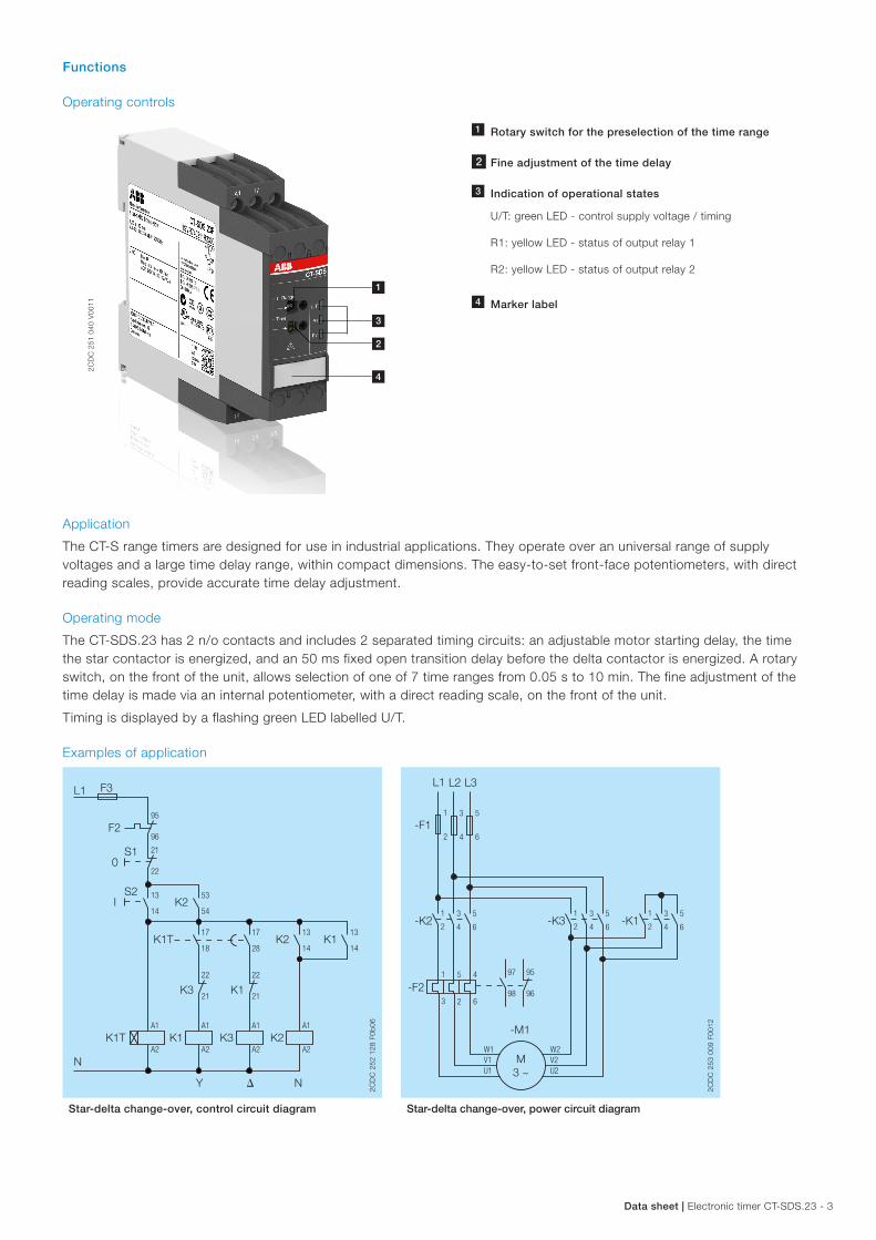
Functions
Operating controls
1 Rotary switch for the preselection of the time range
2 Fine adjustment of the time delay
3 Indication of operational states
U/T: green LED - control supply voltage / timing
R1: yellow LED - status of output relay 1
R2: yellow LED - status of output relay 2
4 Marker label
Application
The CT-S range timers are designed for use in industrial applications. They operate over an universal range of supply voltages and a large time delay range, within compact dimensions. The easy-to-set front-face potentiometers, with direct reading scales, provide accurate time delay adjustment.
Operating mode
The CT-SDS.23 has 2 n/o contacts and includes 2 separated timing circuits: an adjustable motor starting delay, the time the star contactor is energized, and an 50 ms fixed open transition delay before the delta contactor is energized. A rotary switch, on the front of the unit, allows selection of one of 7 time ranges from 0.05 s to 10 min. The fine adjustment of the time delay is made via an internal potentiometer, with a direct reading scale, on the front of the unit.
Timing is displayed by a flashing green LED labelled U/T.
Examples of application
K1T
K1T
K3
K3
Y � N
K2
K2
K2
L1
N
F3
F295
96
21
22
22
21
A1
A2
A1
A2
A1
A2
A1
A2
22
21
13
14
17
18
17
28
13
14
13
14
53
54
S10
IS2
K1
K1
K1
2CD
C 2
52 1
28 F
0b06
-K1-K3
L1
-F11
2
95
96
97
98
L2
3
4
L3
5
6
1
2
3
4
5
6
1
2
3
4
5
6-K2
-F2
1
2
3
4
5
6
1
3
5
2
4
6
M3 ~
W2V2U2
W1V1U1
-M1
2CD
C 2
53 0
09 F
0012
Star‑delta change‑over, control circuit diagram Star‑delta change‑over, power circuit diagram
1
2
4
2CD
C 2
51 0
40 V
0011

4 - Electronic timer CT-SDS.23 | Data sheet
Function diagram
FC Star-delta change-over with impulse
This function requires continuous control supply voltage for timing.
Applying control supply voltage to terminals A1-A2, energizes the star contactor connected to terminals 17-18 and begins the set starting time t1. The green LED flashes during timing. When the starting time is complete, the first output contact de-energizes the star contactor.
Now, the fixed transition time t2 of 50 ms starts. When the transition time is complete, the second output contact energizes the delta contactor connected to terminals 17-28. The delta contactor remains energized as long as control supply voltage is applied to the unit.
A1-A2
t1 t2
2CD
C 2
52 0
40 F
0206
green LED
t1 = adjusted starting timet2 = transition time (50 ms)
17-18
17-28
2CD
C 2
52 0
40 F
0206
Electrical connection
A1
A1
A2 18 28
17
17
18 28 A2
2CD
C 2
52 0
16 F
0b06
2CD
C 2
52 0
16 F
0b06
17-18 1st n/o contact
17-28 2nd n/o contact
A1-A2 Rated control supply voltage US 380-440 V AC
Connection diagram

Data sheet | Electronic timer CT-SDS.23 - 5
Technical data
Data at Ta = 25 °C and rated values, unless otherwise indicated
Input circuits
Versorgungskreis A1-A2
Rated control supply voltage US 380-440 V AC
Rated control supply voltage US tolerance -15...+10 %
Rated frequency DC n/a
AC 50/60 Hz
Frequency range AC 47-63 Hz
Typical current / power consumption 400 V DC 3 mA / 1.2 VA
Power failure buffering time 400 V DC min. 20 ms
Release voltage > 10 % of the min. rated control supply voltage Us
Timing circuit
Kind of timer Single-function timer Star-delta change-over
Time ranges 0.05 s - 10 min 0.05-1 s, 0.15-3 s, 0.5-10 s, 1.5-30 s, 5-100 s,
15-300 s, 0.5-10 min
Recovery time < 60 ms
Repeat accuracy (constant parameters) Δt <± 0.2 %
Accuracy within the rated control supply voltage tolerance Δt < 0.004 %/V
Accuracy within the temperature range Δt < 0.03 %/°C
Setting accuracy of time delay ± 6 % of full-scale value
Star-delta transition time fixed, 50 ms
Star-delta transition time tolerance ± 2 ms
User interface
Indication of operational states
Control supply voltage / timing U/T: green LED V: control supply voltage applied
U/T: green LED W: timing
Relay status R1: yellow LED V: output relay 1 energized
R2: yellow LED V: output relay 2 energized
Output circuits
Kind of output 17-18 relay, 1st n/o contact
17-28 relay, 2nd n/o contact
Contact material Cd-free
Rated operational voltage Ue 250 V
Minimum switching voltage / Minimum switching current 12 V / 10 mA
Maximum switching voltage / Maximum switching current see ‘Load limit curves’ on page 8
Rated operational current Ie AC-12 (resistive) at 230 V 4 A
AC-15 (inductive) at 230 V 3 A
DC-12 (resistive) at 24 V 4 A
DC-13 (inductive) at 24 V 2 A
AC rating (UL 508) utilization category (Control
Circuit Rating Code)
B 300
max. rated operational voltage 300 V AC
max. continuous thermal
current at B 300
5 A
max. making / breaking
apparent power at B 300
3600/360 VA
Mechanical lifetime 30 x 106 switching cycles
Electrical lifetime AC-12, 230 V, 4 A 0.1 x 10⁶ switching cycles
Frequency of operation, with/without load 360/72000 h-1
Maximum fuse rating to achieve short-circuit
protection
n/c contact 6 A fast-acting
n/o contact 10 A fast-acting

6 - Electronic timer CT-SDS.23 | Data sheet
General data
MTBF on request
Duty time 100 %
Dimensions see ‘Dimensional drawing’
Weight Screw connection technology
Easy Connect Technology (push-in)
net 0.118 kg (0.260 lb) 0.112 kg (0.247 lb)
Mounting DIN rail (IEC/EN 60715),
snap-on mounting without any tool
Mounting position any
Minimum distance to other units vertical not necessary
horizontal not necessary
Material of housing UL 94 V-0
Degree of protection housing IP50
terminals IP20
Electrical connection
Screw connection technology
Easy Connect Technology (push-in)
Connecting capacity fine-strand with(out)
wire end ferrule
1 x 0.5-2.5 mm²
(1 x 18-14 AWG)
2 x 0.5-1.5 mm²
(2 x 18-16 AWG)
2 x 0.5-1.5 mm²
(2 x 18-16 AWG)
rigid 1 x 0.5-4 mm²
(1 x 20-12 AWG)
2 x 0.5-2.5 mm²
(2 x 20-14 AWG)
2 x 0.5-1.5 mm²
(2 x 20-16 AWG)
Stripping length 8 mm (0.32 in)
Tightening torque 0.6 - 0.8 Nm
(7.08 lb.in)
-
Recommended screw driver DIN ISO 2380-1: Form A / 0.8x4.0 mm DIN ISO 8764-1: PZ 1 / Ø 4.5 mm
Environmental data
Ambient temperature ranges operation -25...+60 °C
storage -40...+85 °C
Relative humidity range 25 % to 85 %
Vibration, sinusoidal (IEC/EN 60068-2-6) functioning 40 m/s2, 10-58/60-150 Hz
resistance 60 m/s2, 10-58/60-150 Hz, 20 cycles
Vibration, seismic (IEC/EN 60068-3-3) functioning 20 m/s²
Shock, half-sine (IEC/EN 60068-2-27) functioning 150 m/s2, 11 ms, 3 shocks/direction
resistance 300 m/s2, 11 ms, 3 shocks/direction
Isolation data
Rated insulation voltage Ui input circuit / output circuit 500 V
output circuit 1 / output circuit 2 300 V
Rated impulse withstand voltage Uimp input circuit / output circuit 6 kV; 1.2/50 µs
output circuit 1 / output circuit 2 4 kV; 1.2/50 µs
Power-frequency withstand voltage between all isolated circuits (test voltage) 2.0 kV; 50 Hz, 1 min
Basic insulation (IEC/EN 61140) input circuit / output circuit 500 V
Protective separation (IEC/EN 61140; EN 50178) input circuit / output circuit 250 V
Pollution degree 3
Overvoltage category III
Standards / Directives

Data sheet | Electronic timer CT-SDS.23 - 7
Standards IEC/EN 61812-1
Low Voltage Directive 2014/35/EU
EMC Directive 2014/30/EU
RoHS Directive 2011/65/EU
Electromagnetic compatibility
Interference immunity to IEC/EN 61000-6-2
electrostatic discharge IEC/EN 61000-4-2 Level 3, 6 kV / 8 kV
radiated, radio-frequency, electromagnetic field IEC/EN 61000-4-3 Level 3, 10 V/m (1 GHz) / 3 V/m (2 GHz) /
1 V/m (2.7 GHz)
electrical fast transient / burst IEC/EN 61000-4-4 Level 3, 2 kV / 5 kHz
surge IEC/EN 61000-4-5 Level 4, 2 kV A1-A2
conducted disturbances, induced by radio-frequency fields IEC/EN 61000-4-6 Level 3, 10 V
harmonics and interharmonics IEC/EN 61000-4-13 Class 3
Interference emission IEC/EN 61000-6-3
high-frequency radiated IEC/CISPR 22, EN 55022 Class B
high-frequency conducted IEC/CISPR 22, EN 55022 Class B
Technical diagrams
Load limit curves
AC current [A]
resistive loadAC
vol
tage
[V]
2CD
C 2
52 1
49 F
0206
DC current [A]
resistive load
DC
vol
tage
[V]
2CD
C 2
52 1
50 F
0206
2CD
C 2
52 1
50 F
0206
AC load (resistive) DC load (resistive)
cos ϕ
0.5
0.1 0.2 0.3 0.4 0.5 0.6 0.7 0.8 0.9 1.0
0.6
0.7
0.8
0.9
1.0
Der
atin
g fa
ctor
F
2CD
C 2
52 1
24 F
0206
Switching current [A]
250 Vresistive load
Sw
itchi
ng c
ycle
s
2CD
C 2
52 1
48 F
0206
2CD
C 2
52 1
48 F
0206
Derating factor F for inductive AC load Contact lifetime
8 - Electronic timer CT-SDS.23 | Data sheet
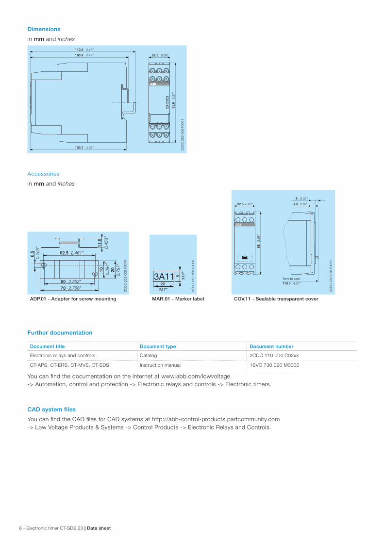
Dimensions
in mm and inches
113.4 4.47”
22.5 0.89”
85.6
3.37
”
103.7 4.08”
105.9 4.17”
2CD
C 2
52 0
09 F
0011
Accessories
in mm and inches
22.5 0.89”
68 2.68
”
110.5 4.31”
8 0.32”
4.8 0.19”
front to back
2CD
C 2
52 0
10 F
0011
6.5 62.5
60
1011
.5
20
0.25
6”
2.461”
2.362”
70 2.756”
0.39
4”
0.78
7”
0.45
3”
2CD
C 2
52 0
08 F
0010
203A11 8
.315
”
.787”
2CD
C 2
52 1
86 F
0005
2CD
C 2
52 1
86 F
0005
ADP.01 ‑ Adapter for screw mounting MAR.01 ‑ Marker label COV.11 ‑ Sealable transparent cover
Further documentation
Document title Document type Document number
Electronic relays and controls Catalog 2CDC 110 004 C02xx
CT-APS, CT-ERS, CT-MVS, CT-SDS Instruction manual 1SVC 730 020 M0000
You can find the documentation on the internet at www.abb.com/lowvoltage -> Automation, control and protection -> Electronic relays and controls -> Electronic timers.
CAD system files
You can find the CAD files for CAD systems at http://abb-control-products.partcommunity.com -> Low Voltage Products & Systems -> Control Products -> Electronic Relays and Controls.

ABB STOTZ-KONTAKT GmbHP. O. Box 10 16 8069006 Heidelberg, GermanyPhone: +49 (0) 6221 7 01-0Fax: +49 (0) 6221 7 01-13 25E-mail: [email protected]
You can find the address of your local sales organization on the ABB home pagehttp://www.abb.com/contacts -> Low Voltage Products and Systems
Contact us
Note:We reserve the right to make technical changes or modify the contents of this document without prior notice. With regard to purchase orders, the agreed particulars shall prevail. ABB AG does not accept any responsibility whatsoever for potential errors or possible lack of information in this document.
We reserve all rights in this document and in the subject matter and illustrations contained therein. Any reproduction, disclosure to third parties or utilization of its contents – in whole or in parts – is forbidden without prior written consent of ABB AG.
Copyright© 2017 ABB All rights reserved
Do
cum
ent
num
ber
2C
DC
111
128
D02
01 (
04/2
017)