Embed Size (px)
Citation preview

AES Talk, UIUC Nov. 29, 2005 1
Electronic Transducers For
Musical Instruments
Professor Steven ErredeDepartment of Physics
The University of Illinois @ Urbana-Champaign

AES Talk, UIUC Nov. 29, 2005 2
Electronic transducers used for amplifying all kinds of musical instruments were developed as a natural consequence of the growth of electrical & electronics industry in the 20th century – advent of electrical power distribution for homes, radio, phonographs, etc. in the 1920’s-30’s. Musicians wanted more volume for traditionally quiet instruments – the guitar in particular (& various forms thereof).
The cumulative investigations & discoveries by manyscientists regarding the nature of electromagnetic force/electromagnetism in the previous centuries, culminating with the work of James Clerk Maxwell (1873) et al., & Albert Einstein (1905) enabled the incorporation of this knowledge into people’s “everyday” world!

AES Talk, UIUC Nov. 29, 2005 3
The earliest musical instrument transducers (ca. ~ 1924) were crude – Lloyd Loar @ Gibson (Kalamazoo, MI) – developed an electric pickup for the viola & string bass – strings passed vibrations through the bridge to a metal diaphragm in proximity to a (weak) iron magnet (no AlNiCo until WW-II!) and a coil, changing magnetic flux through the coil induced an EMF which was (vacuum-tube) amplified. Idea was ~ 10 yrs too far ahead of its time –didn’t catch on – no mass electrical power distribution in place yet!

AES Talk, UIUC Nov. 29, 2005 4
In the ~ mid-1930’s, various companies developed electronic musical instruments – for Hawaiian (lap-steel) guitars & electric spanish guitars. Ro-Pat-In/Electro-String Corp (Now Rickenbacker) developed cast-aluminum “Frying Pan” electric Hawaiian guitar in 1932 (during depths of Great Depression) – it used two horseshoe magnets & a coil of wire for the pickup.

AES Talk, UIUC Nov. 29, 2005 5
Gibson, ca. 1936-7 finally saw the light and also got on the electric Spanish & Hawaiian guitar bandwagons…
Gibson EH-150 (Hawaiian) & ES-150 (Spanish) guitars from this era:

AES Talk, UIUC Nov. 29, 2005 6
The insides/guts of an early Gibson EH-150 Electric Hawaiian guitar, with earliest “Charlie Christian” pickup:

AES Talk, UIUC Nov. 29, 2005 7
1940 Gibson ES-300 with “monster” slanted pickup:
AES Talk, UIUC Nov. 29, 2005 8
WW-II halted further development of the electric guitar. Leo Fender started making lap steel guitars (w/ “direct string” AlNiCo PU’s) and amplifiers shortly after the war ended {K&F (‘45), then Fender (1946-65)}.

AES Talk, UIUC Nov. 29, 2005 9
Gibson also started using the new AlNiCo magnet material for their guitar “staple-pole” & PU-90 pickups. Guitar is 1949 Gibson ES-5N

AES Talk, UIUC Nov. 29, 2005 10
Leo Fender developed first commercial mass-producedsolid-body guitar – a prototype, single pickup Esquire guitar (ca. 1948) and the 2-pickup Broadcaster (1950)
’50 Broadcaster
⇒ ’51 “Nocaster”
⇒ ’52 Telecaster
{Threat of trademark infringement from Gretsch - “Broadkaster” Drum Set}

AES Talk, UIUC Nov. 29, 2005 11
Tele neck & bridge PU’s –AlNiCo-V rod magnets, # 43 (42) AWG enameled copper wire used for neck (bridge) pickup coil. n.b. Tele bridge PU has copper-plated steel “booster” plate.

AES Talk, UIUC Nov. 29, 2005 12
Gibson responded to the solid body guitar challenge from Leo Fender in ~ 1952-3, introducing the “Les Paul” solid body guitar – with two AlNiCo adjustable-pole P-90 “soapbar” pickups (developed in the late 1940’s). P-90 pickups also used in earlier “dog-ear” PU cover versions.

AES Talk, UIUC Nov. 29, 2005 13
Leo Fender responded to Gibson in 1954 with 3-pickup “Stratocaster” guitar… Strat pickups similar to, but not identical to Telecaster’s pickups.
1959 Strat Pickup Set
Eldon Shamblin’s 1954 prototype Fender Strat – shoreline gold with his ’54 Fender “Pro”-Amp

AES Talk, UIUC Nov. 29, 2005 14
In 1957 Seth Lover (a Gibson engineer) developed the “Humbucking” pickup virtually eliminated 60 Hz AC hum pickup – consisted of two side-by-side AlNiCo pickups w/ metal shielding covers, one with reversed magnet and coil polarity – the two coils can be connected either in series (usual – for voltage doubling!) or in parallel (current doubling!) for HB operation.

AES Talk, UIUC Nov. 29, 2005 15
Pickups located at different places along the strings of an electric guitar sense the harmonic content (and relative phases) extant in the standing waves of the strings at that location.
A pickup located near the neck of the guitar primarily senses the fundamental and the lower-order harmonics – sonically, the signal from a neck pickup sounds mellower than a pickup located near the bridge, which primarily senses the higher-order harmonics, and hence sonically has a much brighter sound.
The location of pickups on an electric guitar is not “mindless”. The neck PU’s of the Fender Strat and Tele and pole-adjustment screws of the humbucking neck PU of the Gibson Les Paul are located near the 2nd anti-node (from the nut) of the n = 2 harmonic, and therefore are simultaneously near the 3rd node (from the nut) of the n = 4 harmonic. The middle PU of the Strat is located near the 3rd anti-node (from the nut) of the n = 3 harmonic, and therefore is simultaneously near the 5th node (from the nut) of the n = 6 harmonic.
Thus, when playing open strings on the Strat, Tele or Les Paul with the pickup selector switched to the neck pickup, the 2nd harmonic (4th harmonic) will be enhanced (suppressed), respectively. When playing open strings on the middle pickup of the Strat, the 3rd harmonic (6th harmonic) will be enhanced (suppressed), respectively. The bridge PU on the Strat, Tele or Les Paul is not located near any anti-nodes or nodes associated with the low-order harmonics of the open strings.

AES Talk, UIUC Nov. 29, 2005 16
All kinds of stringed musical instruments were electrified – mandolins, banjos, violins… Solid-body bass guitars were also developed!
’52 Fender Precision Bass ’53 Gibson EB-1 ’56 Fender Mandolin ’58 Fender Violin

AES Talk, UIUC Nov. 29, 2005 17
Fender Electric Mandolin & Electric Violin Pickups:

AES Talk, UIUC Nov. 29, 2005 18
How do electric guitar pickups work?
Pickup Coil
Permanent Magnet
To Amplifier
N
S
Magnetically Permeable Guitar String N S S N
A guitar pickup consists of a permanent magnet (& possibly other magnetically permeable materials (e.g. soft iron)) with a coil of fine-gauge insulated copper wire wound around it, typically # 42 or #43 AWG (φ = 2.5 & 2.2 mils, respectively).
The strings of an electric guitar are made of magnetically permeable material – e.g. stainless steel/nickel alloy. The guitar strings, in proximity to the pickup become magnetized – amazingly, two magnetic poles are induced in the string directly over the pickup (here south poles) – the majority of magnetic flux is confined to the interior the magnetically permeable string – it has two opposite magnetic poles induced at the ends of string (here north poles) – the magnetically permeable guitar string is thus a pair of bucking linear magnetic dipoles, i.e. a co-linear pair of bucking magnetic flux tubes!!!

AES Talk, UIUC Nov. 29, 2005 19
Pickup Coil
Permanent Magnet
To Amplifier
N
S
Magnetically Permeable Guitar String N S S N
When the now-magnetized string(s) of an electric guitar are plucked, ~ triangle-shaped standing waves on the string are set up, consisting of a harmonic superposition of the fundamental, fo = v/2Lscale = v/λo and higher harmonics, fn = n fo; λn = λo/n = 2Lscale/n. {The detailed geometrical shape of the standing wave dictates which harmonics are present (by Fourier’s theorem)!}
The now-magnetized string(s) of an electric guitar vibrating in proximity to the guitar pickup cause changes in the magnetic flux linking the pickup coil and induce an EMF (i.e. a time-varying voltage signal) in the pickup coil (Faraday’s Law of Magnetic Induction):
( ) ( )( ) mcoil
d t dB tt Adt dt
ε Φ= − = −

AES Talk, UIUC Nov. 29, 2005 20
Each mode of vibration of the now-magnetized guitar string has (transverse) displacement amplitude:
( ) sin( )sin( ) sin(2 )sin(2 / )n n n n n n n n ny t a t k z a f t zω ϕ π ϕ π λ= + = +The transverse velocity amplitude associated with each mode of vibration of the guitar string is:
( )( ) cos( )sin( ) 2 sin(2 )sin(2 / )yn n n n n n n n n n ny tv t a t k z f a f t z
tω ω ϕ π π ϕ π λ∂
= = + = +∂
/n o o scale n of nf = nv/ = nv/2L n n = 1,2,3,4....λ λ λ= =
Electric guitar pickups are sensitive to/sense transverse velocity of a vibrating string: For small string displacement amplitudes, the time rate of change of the magnetic flux/magnetic field induced in the pickup coil (and hence the induced EMF) is linearly proportional to the (overall) transverse velocity amplitude of the magnetized string, which (by Fourier’s theorem) is equivalent to the linear superposition of the transverse velocity amplitudes vyn associated with each of the individual modes of transverse vibration of the string:
( )( ) ( )
max
1
( ) ( ) ( )( ) , ( )
, Frequency - dependent Transfer Function
( ) ( )
yn n
yn n
mn n nn coil v n yn yn
v n yn yn n
n
tot nn
d t dB t dI tt A L K f v v tdt dt dt
K f v v
t t
ε
ε
ε
ε
ε ε
→
→
=
Φ= − = − = =
= →
=∑

AES Talk, UIUC Nov. 29, 2005 21
The induced EMF/voltage in the pickup coil and the time rate of change of current induced in the pickup coil (modeled as an ideal/pure inductor) are related to each other via the (self) inductance, L of the pickup coil:
( )max
1
( ) ( )( ) ( ) ( )( ) , ( )
( ) ( )
yn n
cutoff
m
mn n nn coil v n yn yn
n
tot nn
t LI td t dB t dI tt A L K f v v t
dt dt dt
t t
εε
ε ε
→
=
Φ =
Φ= − = − = − =
= ∑The (complex) impedance, Z (AC/dynamic resistance) of a pickup coil (modeled as an ideal/pure inductor)
using the generalized form of Ohm’s law is:
( ) { }
( ) / ( ) ( ) / ( ) ( )
( ): ( ) ( ) 1
( ) / ( ) ( ) / ( ) ( ) / ( ) 22
n
n n n n
i tonn
n n n
n n n n n n n n n
n n
Z V t I t t I t sign Back EMF due to Lenz's Law!
d I edI tBut t L L i LI t idt dt
Z V t I t t I t i LI t I t i L i f LZ i L i f L
ω
ε
ε ω
ε ω ω πω π
= = − − ⇒
= − = − = ≡ −
= = − = + = == =

AES Talk, UIUC Nov. 29, 2005 22
Thus, the simplest physical model of an electric guitar pickup is that of an inductor (actually a choke – including the magnetic materials of the PU) – an EMF, ε(t) is induced in the pickup coil due to time-varying magnetic flux linking the pickup coil, which in turn creates an electrical current I (t) in the pickup coil (provided the pickup is hooked up to an external circuit).
Electric guitar pickups {should be considered as/} are intrinsically high output impedance devices (over the audio frequency range 20 Hz - 20 KHz). Thus, they are connected to high input impedance voltage amplifiers (with typical “industry standard” input impedance of Zin = 1 Meg-Ohm).
The voltage output from a guitar pickup is V(t) = ZI(t), typically ~ O(few x 100 mV) for Fender Strat/Tele single-coil PU’s, and typically ~ 2x this for Gibson humbucker & P-90 PU’s.
RLoad = 1 MΩI(t)V(t)Guitar PU
Simplest Model of an Electric Guitar Pickup:
Frequency, f (Hz)
Z(f) (Ohms) V(f) (Volts)
@ I = Constant Current
Excitation
|Z(f)| = ωL = 2πfL
V(f) = I Z(f) = 2πfIL
Academic/ivory-tower scientific approach to electric guitar pickup studies: Assume electric guitar pickup is excited @ constant current –equivalent to regular-tuned (EADGBE) guitar strung with all the same gauge strings and each string plucked exactly the same way/same force. n.b. Elo ~ 82.5 Hz, Ehi = 4Elo ~ 330 Hz. But don’t forget/also keep in mind the higher harmonics!!!

AES Talk, UIUC Nov. 29, 2005 23
The simplest model of a guitar pickup is a (very!) poor approximation to a real pickup for a (large!) number of reasons:
1.) A real, physical inductor (pickup coil) has a dc resistance, Rdc (42 AWG (φ = 2.5 mils) ~ 1.6 Ohms/ft, 43 AWG (φ = 2.2 mils) ~ 2.1 Ohms/ft). Electric guitar pickup coils typically have several thousand turns (P-90’s have 10K turns!), thus a typical electric guitar pickup has a lumped dc (i.e. f = 0 Hz) coil resistance of Rdc ~ several–10K Ohms. This lumped dc resistance, Rdc is in series with the lumped inductance, L of the guitar pickup.
2.) Because pickup coils have resistances associated with them and a large number of turns of wire, the turn-to-turn capacitances, dC = Q(t)dV(t) (very small, ~ O(< 1 pF) build up to a non-negligible, net, or lumped capacitance, C associated with the pickup, which is typically ~ few 10’s–100 pF. This lumped capacitance, C associated with the guitar pickup is in parallel with the lumped {inductance, L + dc resistance, Rdc} of the guitar pickup.
The (complex) impedance of a capacitor is ZC = 1/iωC = 1/i2πfC, thus the magnitude of the capacitor’s impedance is | ZC | = 1/ωC = 1/2πfC ~ 1/f. Thus, | ZC (f → 0)| →∞ whereas | ZC (f →∞)| → 0. Thus, at low frequencies, the lumped capacitance of a guitar pickup has little impact. However, at higher & higher frequencies, the lumped capacitance of a guitar pickup has increasingly significant impact – as the frequency of the signal induced in a guitar pickup increases, the pickup capacitance increasingly shunts (i.e. shorts-out) the induced signal in the pickup to ground! The larger this capacitance, the worse this effect!

AES Talk, UIUC Nov. 29, 2005 24
RLoad = 1 MΩI(t)V(t)Guitar
PU
A Better Model of an Electric Guitar Pickup:
LPU
CPURDC
fo
Frequency, f (Hz)
ZPU(f) (Ohms) VPU(f) (Volts)
@ I = Constant Current
Excitation
|ZL(f)| = ωL = 2πfL
|ZC(f)| = 1/ωC = 1/2πfC
ZPU(fo)
VPU(fo)

AES Talk, UIUC Nov. 29, 2005 25
Llo
Lhi
Clo
Chi
Increasing Pickup
Capacitance, CPU
Increasing Pickup
Inductance, LPU
Frequency, f (Hz)
Pickup Impedance, ZPU(f)
or
Pickup Output Voltage VPU (f)
@ I = Constant Current Excitation
Effect of Varying Pickup Capacitance and Pickup Inductance:
Increasing the pickup inductance, LPU increases pickup output signal, V(f,t). If this is done simply by increasing # turns of pickup coil, this necessarily increases (lumped) pickup capacitance, which a.) kills pickup output, and b.) also moves pickup’s resonant frequency, fo lower (fo ~ 1/Sqrt[LPUCPU]) – sonic impact on guitar pickup: for fixed inductance, pickup with high overall winding capacitance sounds “dead” (less lively) and dull (less detail/ less “shimmer”/sparkle), compared to same pickup with less overall winding capacitance.

AES Talk, UIUC Nov. 29, 2005 26
Coils on vintage electric guitar pickups (1930’s – 1960’s) were all wound by hand – mostly by women employees. Hand wound pickups are, by their very nature scatterwound/randomly wound. All Fender electric guitar PU’s were wound by hand until bought out by CBS in 1965. Similarly, all Gibson electric guitar PU’s were wound by hand until ~ late 1960’s. After that, Fender/Gibson & many other guitar-manufacturing companies machine-wound all of their pickups.
⇒You can very definitely hear/experience the difference!!! ⇐
Which PU’s sound better? There are no absolutes, because “Beauty is in the ear of the beholder” but I personally (strongly) prefer the sound of the hand-wound vintage electric guitar pickups over that of the modern, “exact” replicas of such pickups that are machine-wound…
With today’s computer-controlled coil-winding machines that are used for mass-production winding of electric guitar pickups, these machines do indeed lay down very nice/neat turns of wire for the pickup coil, which simultaneously maximizes the pickup coil’s inductance .and. the pickup coil’s capacitance, the latter killing the pickup’s output at the higher frequencies.
However, it would be extremely easy to modify the winding algorithms in these machines to (slightly) randomize the winding to mass-produce (essentially) true scatterwound pickups. Why this hasn’t yet been done is a mystery to me…
AES Talk, UIUC Nov. 29, 2005 27
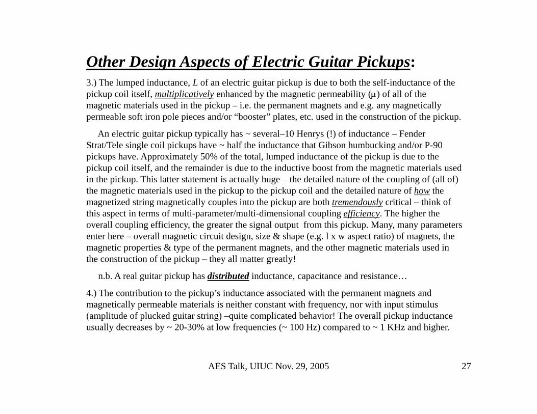
Other Design Aspects of Electric Guitar Pickups:3.) The lumped inductance, L of an electric guitar pickup is due to both the self-inductance of the pickup coil itself, multiplicatively enhanced by the magnetic permeability (μ) of all of the magnetic materials used in the pickup – i.e. the permanent magnets and e.g. any magnetically permeable soft iron pole pieces and/or “booster” plates, etc. used in the construction of the pickup.
An electric guitar pickup typically has ~ several–10 Henrys (!) of inductance – Fender Strat/Tele single coil pickups have ~ half the inductance that Gibson humbucking and/or P-90 pickups have. Approximately 50% of the total, lumped inductance of the pickup is due to the pickup coil itself, and the remainder is due to the inductive boost from the magnetic materials used in the pickup. This latter statement is actually huge – the detailed nature of the coupling of (all of) the magnetic materials used in the pickup to the pickup coil and the detailed nature of how the magnetized string magnetically couples into the pickup are both tremendously critical – think of this aspect in terms of multi-parameter/multi-dimensional coupling efficiency. The higher the overall coupling efficiency, the greater the signal output from this pickup. Many, many parameters enter here – overall magnetic circuit design, size & shape (e.g. l x w aspect ratio) of magnets, the magnetic properties & type of the permanent magnets, and the other magnetic materials used in the construction of the pickup – they all matter greatly!
n.b. A real guitar pickup has distributed inductance, capacitance and resistance…
4.) The contribution to the pickup’s inductance associated with the permanent magnets and magnetically permeable materials is neither constant with frequency, nor with input stimulus (amplitude of plucked guitar string) –quite complicated behavior! The overall pickup inductance usually decreases by ~ 20-30% at low frequencies (~ 100 Hz) compared to ~ 1 KHz and higher.

AES Talk, UIUC Nov. 29, 2005 28
5.) The type of permanent magnets (AlNiCo V, II or III, or Ceramics, or Rare Earth) used in the pickup and the details of the magnetic properties of the permanent magnets matter greatly. The sonic properties of pickup also depends on how “fully charged” the permanent magnets are, because all permanent magnets, as well as magnetically permeable materials such as soft iron pole pieces, copper or zinc-coated mild-steel booster plates, etc. also have non-negligible/non-trivial, frequency and signal amplitude-dependent power dissipation (i.e. power losses) associated with them. Can hear the difference here also from these effects!!!
6.) The wire type, composition, annealing & wire-drawing process, batch #, the insulation coating (varnish, enamel, formvar, …) on # 42/43 AWG wire used for winding pickup coils also matters greatly! There exists some very interesting materials physics and E&M phenomena going on here – just with (very thin) wire!! e.g. the AC resistance ≠ DC resistance due to skin effect(s) & B-field effects in wire.... Can hear the difference!!!
7.) Non-magnetic metal pickup shielding covers (if used) as well as e.g. copper or zinc-plated mild steel booster plates and use of metal pickup frames also have sonic impact on the pickup output – due to a.) frequency-dependent induced eddy currents (also buck change in magnetic flux) and b.) increased pickup capacitance. Removing covers results in sonically brighter, more aggressive sound – i.e. sonic impact of having metal pickup shielding covers reduces higher harmonic content of nascent pickup signals and softens “attack”. Again, can (easily) hear the difference!!!
8.) The details of the material composition, annealing/drawing processes, string type (e.g. plain vs. wound) & string gauge (diameter) of the magnetically permeable strings of an electric guitar also matter greatly – they arepart of the magnetic (& electromagnetic) circuit of the guitar pickup! Again, can hear the difference!
These facts (and others) make realistic, quantitative and sophisticated “first-principles” modeling of an electric guitar pickup extremely difficult…. A challenge!!!

AES Talk, UIUC Nov. 29, 2005 29
RLoad = 1 MΩI(t)V(t)Guitar
PU
A More Sophisticated Model of an Electric Guitar Pickup:
LPU(V, f)
CPU(V, f)
RPU(V, f) RMD(V, f)
( ) ( ) ( ) ( )( ) ( ) ( )( ) ( ) ( )( )
( ) ( ) ( )( ) ( ) ( )( ) ( ) ( ) ( ) ( )( )
1 2
1 1 1L L
tot PU L MD C
tot PU L MD C PU MD L C
L C f
Z R i R i
Z R i R i R R i i
χ ω ω ω χ ω ω ω ω π
ω ω χ ω ω χ ω
ω ω χ ω ω χ ω ω ω χ ω χ ω
≡ ≡ =
= + + −
= + − + + −
Rationalize:
Define inductive and capacitive reactances, then compute output impedance of electric guitar pickup:
( ) ( )( ) ( )
( ) ( )( ) ( )
( )( ) ( )( ){ } ( )( ) ( )( ){ }( ) ( )2 2
PU MD L C L PU C MD PU MD L Ctot
PU MD L C PU MD L C
PU MD L C PU MD L PU C MD L C L PU C MD PU MD PU MD L C L Ctot
PU MD L C
R R i R R R R iZ
R R i R R i
R R R R R R i R R R R R RZ
R R
χ χ χ χ χ χχ χ χ χ
χ χ χ χ χ χ χ χ χ χ χ χ
χ χ
+ + − + − −= ∗
+ + − + − −
+ + + − − + + + − + −=
+ + −

AES Talk, UIUC Nov. 29, 2005 30
This gives the real and imaginary parts – i.e. the resistance & reactance associated with total impedance:
( )( ) ( )( )( ) ( )
( ) ( )( ) ( )
( )( ) ( ) ( )( ) ( )
( ) ( )( ) ( )
2 2 2 2
2 2 2 2
2 2 2 2
2 2 2
tot tot tot
PU C MD MD L PUPU MD L C PU MD L PU C MD L Ctot
PU MD L C PU MD L C
L C MD C L PUL PU C MD PU MD PU MD L C L Ctot
PU MD L C PU MD L C
Z R i
R R R RR R R R R RR
R R R R
R RR R R R R RR R R R
χ
χ χχ χ χ χ χ χ
χ χ χ χ
χ χ χ χχ χ χ χ χ χχ
χ χ χ χ
≡ +
+ + ++ + + − −= =
+ + − + + −
+ − ++ + − + −= =
+ + − + + − 2
The resonant frequency of the electric guitar pickup can be found by setting the total reactance to zero:
( ) ( ) ( )( )( )
2 2 2 2
2
2
0
12
tot res L C MD C L PU
PUres res
MD
f f R R
L C Rf
L C RLC
χ χ χ χ χ
ω π
= = ⇒ + = +
−⇒ = =
−
Remember, output voltages V(f ) on (or off) the resonant peak scale directly with impedances (V = IZ), assuming constant current excitation….
When f = fres, the complex impedance Z(fres) of an electric guitar pickup is purely real and is a maximum:
( ) ( )( ) ( ) ( )( ) ( ) ( ) ( )( )
( ) ( )( )
2 2 2 2
2PU res C res MD res MD res L res PU resmax
tot res tot res
PU res MD res
R f f R f R f f R fZ f f R f f
R f R f
χ χ+ + += = = =
+

AES Talk, UIUC Nov. 29, 2005 31
The FWHM (full width at half maximum (power)) width of an electric guitar pickup resonance, the resonance quality factor, Q and resonance dissipation factor, D are defined as:
( ) ( )( ) ( )
@ 2 @ 2
Im Im@ 0 @ 0
1of resonance : , Dissipation,
Hi Lores Hi res Lo res
Hi Lores res
res Hi Lo
res res
res res
f f Z f Z
Z Zf f f
f f
f fQ Q Df Q f
Δ ≡ −
⎛ ⎞ ⎛ ⎞∂ ∂⎜ ⎟ ⎜ ⎟Δ ≡ = − =⎜ ⎟ ⎜ ⎟∂ ∂⎝ ⎠ ⎝ ⎠
Δ≡ = ≡Δ
The width of an electric guitar pickup resonance is also extremely important sonically – when two or more pickups that are sensing different harmonic content(s) of string vibration(s) due to differing pickup locations (and that are properly balanced, output signal-wise) are electrically combined– very delicate, frequency-dependent constructive & destructive interference of the two (or more) voltage signal amplitudes occur, resulting in an overall output voltage signal which is sonically unique – e.g. the famous, glassy “in-between” middle+bridge PU combination sounds of Strat single-coil PU’s, or the neck+bridge PU combination sounds of Tele single-coil PU’s. It is predominantly the higher harmonic frequencies that are emphasized in these “in-between” sounds; the fundamental frequencies tend to (partially) cancel….
Even for single pickups alone, the width of the pickup resonance is sonically noticeable, because a PU with a wider/broad resonance (i.e. low-Q, high-D – e.g. ~ 50%-charged AlNiCo-III magnets as used in the earliest ’54 Strats) has significantly more midrange “honk” to it than an identical PU, except it having a narrowresonance width (i.e. high-Q, low-D, from fully charged permanent magnets)...
The width of an electric guitar pickup resonance (not easy to see from above formulae) is due to / determined by the pickup’s resistance & dissipation in magnetic materials of pickup, as well as the resistance of the load resistor (guitar volume control and/or amplifier input impedance resistor (typically 1 Meg-Ohm).

AES Talk, UIUC Nov. 29, 2005 32
Physical Measurements of Electric Guitar Pickups @ UIUC:In the UIUC Physics 498 Physics of Music/Musical Instruments Lab, we routinely
measure the following properties of any/all electric guitar pickups that we are interested in (hundreds have now been measured):
1.) Specs & physical dimensions of all pickup components, component materials.
2.) Measure DC resistance of PU using Fluke 77 DMM.
3.) Measure magnetic polarity of PU – using compass (or Hall probe) @ top of PU.
4.) Determine winding direction (CW or CCW) of PU, viewed from top of PU.
5.) Measure (max) on-contact B-field of permanent magnets @ PU poles using Hall probe.
6.) Measure PU L ©, Q & D-factors at f = 120 Hz, 1 KHz (10 KHz) using HP LCR meter.
7.) Measure PU Z(f) over audio frequency range using PC-based DAQ system.
8.) Investigate PU distortion properties using function generator & HP spectrum analyzer.

AES Talk, UIUC Nov. 29, 2005 33
The UIUC Physics 498POM PC-Based Pickup Impedance Measuring System:
PC
Nat’l Inst
LabPC+ DAQ Card
Sine-Wave Function GeneratorGPIB
CableMonitor
+
−
AD624
+
−
AD624
1.5 MΩ
metal film
AD624 low-noise, high input impedance differential /
instrumentation op-amps are used as unity-gain buffer/drivers (i.e. low output impedance)
100 Ω
metal film
ZPickup
SRS-830 DSP I-Lock-In Amplifier
VPU(t)
IPU(t)
Ref In
Ref In
SRS-830 DSP V-Lock-In Amplifier
V Sig In
I Sig In
Gnd
Lock-In Amplifier Reference Signal
Re(V) Im(V)
Re(I) Im(I)
ADC 3 2 1 0
Re(V)
Im(V)
Re(I)
Im(I)
Keyboard
n.b. Re(I) & Im(I) actually computed in software from:
I = V100 Ω /100 Ω
IPU (t)
IPU (t)
IPU (t)

AES Talk, UIUC Nov. 29, 2005 34
The UIUC Physics 498POM PC-Based Pickup Impedance Measuring System:DAQ program (Nat’l Inst. Labwindows/CVI) does the following data-taking I/O:
1.) Initializes Nat’l Inst. LabPC+ DAQ & GPIB interface.
2.) Sets HP function generator to 1 Volt amplitude sine wave @ finit = 5 Hz (excites PU comparably to playing guitar)
3.) Takes 4000 measurements each of ADC0,1,2,3 voltages (to suppress ambient noise fluctuations/RFI).
4.) Computes (pedestal/voltage-offset subtracted) mean of each ADC channel, then computes:
Re(V) = <ADC0> (component of pickup voltage in-phase/−180o out of phase with signal generator).
Im(V) = <ADC1> (component of pickup voltage ±90o out of phase with signal generator).
Re (I) = <ADC2>/100 Ω (component of current in-phase /−180o out of phase with signal generator).
Im (I) = <ADC3>/100 Ω (component of current ±90o out of phase with signal generator).
5.) Compute complex impedance, Z(f)=V(f)/I(f) and complex power, P(f) at this frequency, store info in arrays.
6.) Step frequency of HP function generator by Δf = 10 Hz, wait ~5 seconds for lock-in amplifiers to stabilize.
7.) Then go to step 3 above, and repeat this process 2000x (final frequency, ffinal = 20005 Hz).
8.) When program completes data-taking (~3 ½ hours!), write out all data, look at all 21 on-line plots…
n.b. The function generator behaves as a nearly ideal voltage source (FG Zout = 50 Ω) as long as the load impedance, Zload >> 50 Ω. However the “output side” of the 1.5 MΩ resistor behaves like a nearly ideal/constant current source, as long as the impedance of its load is Zload >> 1.5 MΩ, which is not true on the resonant peak of an electric guitar pickup, typically Zload(fres) ~ 0.5-1.0 MΩ. Thus the current through the pickup will change ~ 20-30% because of this. This is precisely why we explicitly measure the complex current at each frequency. Thus the determination of pickup’s complex impedance is not affected by our inability to maintain constant current.

AES Talk, UIUC Nov. 29, 2005 35
Calculation of Complex Impedance, Z:We measure the real (in-phase) & imaginary
(±90o out-of-phase) components of the complex voltage V(f ) and complex current I(f ) at each frequency 5 Hz < 20 KHz in 10 Hz steps using two lock-in amplifiers referenced to the signal output from the HP function generator. The complex impedance, Z(f ) = V(f )/I(f ).
Suppressing the explicit frequency dependence (f ), we have:
( ) ( )( ) ( )
( )( ) ( )2 2
1, * 1, * * 1Re Im
Re Im
r i
r i V i r
r i I i r
r i r i r iZ i r
r i r i r i
r i r i r r i i
i i i i i iiV V i V V iV tan V V
I I i I I iI tan I IV iV V iV I iIVZ tan Z Z
I I iI I iI I iIV iV I iI V I V I i
ZI I
ϕ
ϕ
ϕ
≡ − − ≡ = − − = = +
= + ≡ + ⇒ =
= + ≡ + ⇒ =
+ + −= = = ∗ ⇒ =
+ + −
+ − + += =
+( )
( ) ( )
( ) ( )
( ) ( )
( )( )( )( )
2 2
2 2 2 2
2 2 2
2 2 2
2 * * 2 2
2 * * 2 2
2 *
r i
r i r i
r i
r i
i r r i
r r i i i r r ir i
r r i i r r i ir
i r r i i r r ii
r i r i r i
r i r i r i
V I V II I
V I V I V I V IZ i Z Z
I I I I
V I V I V I V IZ
I I I
V I V I V I V IZ
I I I
V VV V V V iV V iV V V
I I I I I I iI I iI I I
Z ZZ Z
−+
+ −= + = +
+ +
+ += =
+
− −= =
+
≡ = = + − = +
≡ = = + − = +
≡ = ( )( )* 2 2r i r i r iZ Z iZ Z iZ Z Z= + − = +
ϕ
Re(A) = Ar
= |A|cosϕ
Im(A) = Ai
= |A|sinϕ
A
Real Axis
Imaginary Axis
A = Ar + iAi = |A|eiϕ
= |A|{cosϕ + i sinϕ}
* 2 2r iA AA A A= = +

AES Talk, UIUC Nov. 29, 2005 36
Calculation of Complex Power, S:Electrical power, even if complex, is additive
(i.e. principle of linear superposition must hold).
( )( ) ( ) ( )
1 1 1
* 2 2 2
*
Re( ) Im( ) tan
Apparent Power :
Real Powe
S
N N N
tot k k k tot totk k k
*r i r i r i
r i r i r r i i i r r i
S S i S P iQ Q P
S S P i Q P iQ
S SS S P Q
S V I V = V iV I = I iI I = I iIS V iV I iI V I V I i V I V I
ϕ
= = =
= + ≡ + ⇒ =
= = + = +
= = = +
≡ ⋅ + + −
= + − = + + −
∑ ∑ ∑
( )( )
( ) 2* * *
2
r : Re( )
Reactive Power : Im( )PF Power Factor (%) 100cos
Now : tanResistance Reactance
r r i i
i r r i
S
r i Z
S P V I V I
S Q V I V I
V = I Z Z = Z iZ R i RR =
S V I I Z I I I Z I Z
S I Z
ϕ
χ ϕ χχ
≡ = +
≡ = −
≡ ≡
⋅ + = + ==
≡ ⋅ = ⋅ ⋅ = ⋅ =
= ( )
( ) ( )
2 2 2
2
2
2 2 2
1 1
Real Power :
Reactive Power :
Apparent Power :
n.b. we also see that : tan tanS Z
I R i I R i I P iQ
P I R
Q = I
S I Z Z R
Q P R
χ χ
χ
χ
ϕ χ ϕ− −
= + = + = +
∴ =
∴
∴ = = +
= = =

AES Talk, UIUC Nov. 29, 2005 37
UIUC Physics 498POM Pickup Measurements Test Stand:

AES Talk, UIUC Nov. 29, 2005 38
A Comparison of Impedances of Vintage ’54 Strat Pickups vs. Modern Strat Pickups:
n.b. Real-deal Aug. ’54 Strat Alnico-III PU’s ~ 50% charged vs. 2004 50th Anniv. Am. Std. ’54 RI Strat Alnico-III PU’s.

AES Talk, UIUC Nov. 29, 2005 39
A Comparison of Impedances of Vintage 50’s Gibson P-90 Pickups vs. Modern Gibson P-90 Pickups:
n.b. Real-deal ’52 Les Paul P-90’s used cloth coax cable (no paraffin wax) Real-deal ’57-58 Les Paul P-90’s used paraffin-impregnated cloth coax cable…

AES Talk, UIUC Nov. 29, 2005 40
Other Types of Musical Instrument Transducers:The electromagnetic technology used in conventional/traditional permanent magnet + coil-
type electric guitar pickups has been around for more than ~ 80 years, and has steadily, but incrementally been refined during this time.
Nowadays, there are several other kinds of musical instrument transducers:
1.) Piezo-Electric Transducers:
The most popular “modern-day” transducer is the piezo-electric transducer (initially used in microphones decades ago), which produces an output voltage ~ linearly proportional to a mechanical stress/strain, which is in turn caused by a mechanical displacement. Thus, piezo-electric transducers e.g. mechanically integrated into the bridge of any stringed instrument (acoustic/electric guitars, violins, cello, double bass, mandolins, etc.) are particularly efficacious in converting the mechanical vibrations of the bridge into an output signal.
Piezo-electric transducers are intrinsically very high output impedance devices, but thanks to today’s integrated circuit technology, low-noise, low power-consumption JFET-based analog op-amps (also with extremely high input impedances) are often used in piezo preamp circuits (located in proximity to the piezo-electric transducers themselves). The preamp’s low output impedance then easily drives the cable connecting the musical instrument to an amplifier, without loading and/or little frequency dependence. Fishman (www.fishman.com) is the leading manufacturer of such devices.

AES Talk, UIUC Nov. 29, 2005 41
2.) Hall-Effect Transducers:
In 1879 Edwin Hall discovered that a small potential difference is created transverse to the flow of a current in a conductor when it is immersed in a magnetic field that is perpendicular to both current flow in the conductor and the axis from which the potential difference is measured. The Hall effect is most pronounced in semi-conducting materials. Today, 3-lead analog (i.e. linear) Hall sensors with sensitivity to ~ 1 Gauss changes in magnetic field are available. Since modern linear Hall sensors are integrated circuits, they have intrinsically low output impedance.
Using a permanent magnet in proximity to the (magnetically permeable) strings of a stringed instrument (needed to provide the necessary string magnetization), with a bank of Hall sensors located in the gap between magnet and strings, voltage signals are induced in the Hall sensors when the magnetized strings vibrate – the Hall signal is thus proportional to the transverse displacement amplitude(s) of the string(s).
The sonic properties of “Hall pickups” differ noticeably e.g. in comparison to traditional permanent magnet + coil electric guitar pickups – their frequency response is much flatter, “hi-fi” sounding – potentially useful for low-distortion faithful reproduction type applications - e.g. acoustic guitar, electric bass guitar, violin, mandolin, etc. Allego-Micro (www.allegromicro.com) is one of the leading producers of linear Hall effect sensors.
Allegro 1321 Linear Hall Effect Sensor
(5mV/Gauss)

AES Talk, UIUC Nov. 29, 2005 42
3.) GMR (Giant Magnetic Resonance) Transducers:
GMR transducers are a considerably more modern, “high-tech” devices, fairly recently developed as a spin-off associated with the very rapid advances in hard-disk drive digital data-storage technology in the past ~ decade or so. Certain classes of conductors change their resistance in the presence of an applied magnetic field, hence the name magnetoresistance. Use of e.g. molecular beam epitaxy enables people to atomically grow thin 2-D layers of such materials on a substrate to make B-field sensors.
GMR sensors can be used in musical instrument applications, similar to Hall effect sensors – again, a permanent magnet (or just magnetized strings) is required, and GMR sensors also need voltage biasing as well (typically +5V). Since the resistance of GMR sensors is typically ~ few K-Ohms, they are again intrinsically low output impedance devices. GMR sensors e.g. for bass guitar use have been developed by Dr. Gary Nelson of Quanta-Sonics (Port Townsend, WA) and are currently in use in the high-tech Moses graphite upright basses. (www.mosesgraphite.com)
The output from an NVE low-field giant magnetoresistive sensor (NVE AA002-02) shows high sensitivity with both positive and negative fields (4 mV/V/Oe to 40 mV/Oe with 10 V excitation). The hysteresis shown is observed only during a full bipolar sweep of the applied field. The hysteresis for small excursions of the applied field is much smaller.
SME tested a prototype solid-body bass guitar with Quanta-Sonics GMR sensors a while back and was quite impressed with its tonal properties!

AES Talk, UIUC Nov. 29, 2005 43
Summary/Conclusions:1.) It is very difficult to go much into the fascinating gory details of many, many aspects and amazing technical history of electric guitar pickups in a short talk like this one – e.g how guitar pickup is loaded by volume & tone controls, guitar cable; pickup switching/pickup combinations; passive {pickups & controls} vs. active {pickups & controls}… all have profound effect(s) on the tonal/sonic properties of the guitar – info could very easily fill a semester-long course!!!
2.) Didn’t even get to talk about the microscopic/quantum/particle-physics aspects of what-all is going on in electric guitar pickups, which blows my mind – and your ear can hear this!!!
3.) More transducers out there than just one type – doubtless new ones can/will also be developed – perhaps this will lead to whole new classes of musical instruments being developed!!!
However, be forewarned: “Just because someone has a clever idea or a great new transducer, doesn’t automatically/necessarily mean it will sound good!!!”
4.) Nevertheless, hope this talk gives you some flavor of all sorts of interesting & exciting things that, coupling knowledge of physics/science with music, together they can be synergistically used to “push the envelope” further/higher!!!
5.) Basic science R&D, and the subsequent technological integration of the knowledge gained from basic science R&D can be used for society’s benefit in many ways – however note that the timescales are such that it often takes decades, if not centuries to accomplish this!!!
6.) Thanx so much for inviting me here to give this talk!!!