Embed Size (px)
Citation preview
Installation, Maintenance and User Instructions
Please read these instructions carefully before commencing installation of the InLine water heater.Please leave these instructions with the end user after installation.
Zip Heaters (UK) Ltd14 Bertie Ward WayDerehamNorfolkNR19 1TE
Telephone 0845 6024533Facsimile 01362 692448www.zipheaters.co.uk
Zip InLineElectronically Controlled Instantaneous
Water Heaters
Models CEX-O & CEX-UIssued August 2011
The terms ‘Zip’ and ‘InLine’are registered trademarks.
9120 - 2546
CEX cover qxd:Varipoint cover qxd 17/10/11 16:41 Page 1
ContentsDescription 2
Approvals 2
Warnings 3
Technical data 4
Dimensions 5
Spare parts 6
Installation
Requirements 7
Installation site 7
Installing the appliance 8
Electrical connection 9
Commissioning 10
Service menu 12
Operation 14
Cleaning and maintenance 17
Fault finding 17
Warranty 18
The use of this crossed out wheeled bin logo indicates that this product needsto be disposed of separately to any other household waste.
Within each of the European Union member countries, provisions have beenmade for the collection and recycling of unwanted electrical and electronicequipment.
In order to preserve our environment we ask that you dispose ofthis product correctly. Please contact Zip Customer Service foradvice on 0845 602 4533.
WarrantyThe Zip appliance you have chosen is precision-built from the finest materialsavailable and should give many years of trouble free service.
Certain warranties may be implied by law into your contract with Zip. Thewarranty provided below is additional to these implied warranties and nothingset out below shall limit your statutory rights or rights at law.
Zip Heaters (UK) Ltd warrants that, should any part fail within 12 calendarmonths of installation, that part will be repaired or replaced free of charge by Zipor its Distributor or Service Provider, except as set out below, provided theappliance is installed and used strictly in accordance with the instructionssupplied, and that failure is not due to accident, misuse, abuse, unsuitablewater conditions, or to any alteration, modification or repair by any party notexpressly nominated by Zip.
No costs are payable by the customer other than any mileage or travelling-timecharges incurred by a Zip Service Provider or the cost of removal, cartage andre-installation of any component of the appliance if it needs to be returned forrepair to Zip or its Distributor.
This warranty does not cover damage resulting from non-operation of theappliance or consequential damage to any other goods, furnishings or property.
Zip does not exclude, restrict or modify any liability that cannot be excluded,restricted or modified or which cannot, except to a limited extent, be excluded,restricted or modified as between the owner or user and Zip under the lawsapplicable.
Furthermore, this warranty does not displace any statutory warranty, but, to theextent to which Zip is entitled to do so, the liability of Zip under any statutorywarranty will be limited at Zip's option to the replacement of the appliance orsupply of equivalent appliance, the payment of the cost of replacing theappliance or acquiring an equivalent appliance, or the payment of the cost ofhaving the appliance repaired or the repair of the appliance.
CEX-O & CEX-U Installation, Maintenance and User Instructions - August 2011 181 CEX-O & CEX-U Installation, Maintenance and User Instructions - August 2011
CEX cover qxd:Varipoint cover qxd 17/10/11 16:41 Page 2
CEX-O & CEX-U Installation, Maintenance and User Instructions - August 2011 2
DescriptionZip InLine CEX-O and CEX-U instantaneous water heaters are micro-processor controlled,pressure resistant water heaters suitable for supplying hot water to one or more outlets.
The heating element switches on automatically when the hot water tap is opened andswitches off automatically when the hot water tap is closed.
The electronic control system automatically regulates the power consumptiondepending on the supply water temperature and flow rate to achieve the required outlettemperature within the power limit of the appliance.
Power consumption is also regulated based on outlet temperature to ensure therequired temperature is achieved exactly to the degree and irrespective of fluctuations involtage and water pressure.
The power rating of the appliance can be selected as either 9.6kW or 7.2kW at 240V atthe time of installation.
The required outlet temperature can be entered on a keypad within the range 30°C to55°C and can be read off the digital display.
The maximum inlet temperature of 70°C is suitable for use with preheated water e.g.from solar heating systems.
ApprovalsZip InLine CEX-O and CEX-U are VDE approved to the LVD and EMC directives and areCE endorsed.
Zip InLine CEX-O and CEX-U have been examined, tested and found when correctlyfitted to comply with the requirements of the United Kingdom Water Regulations /Byelaws (Scotland). The products are listed under the WRAS (Water RegulationsAdvisory Scheme) Water Fittings and Materials Directory.
CEX pages qxd:Varipoint qxd 30/8/11 14:27 Page 1
3 CEX-O & CEX-U Installation, Maintenance and User Instructions - August 2011
Warnings• Installation, commissioning and maintenance of this appliance must only be carried
out by a competent installer who will then be responsible for adhering to all relevantstandards and regulations.
• The appliance must only be used when correctly installed and in perfect working order!
• The appliance must be installed in a frost-free room! The appliance must never beexposed to frost.
• The appliance must be earthed at all times!
• The appliance must only be used for heating potable water. The specific waterresistance must not fall below the required value indicated on the rating plate.Theappliance must not be used for any other purpose.
• The maximum water pressure must not exceed the value indicated on the rating plate.
• The incoming water temperature must not exceed 70°C.
• Before commissioning for the first time and each time the appliance is emptied (e.g. dueto work on the plumbing system, if there is a risk of freezing or in case of maintenance),the appliance must be vented by opening and closing the hot water tap until all air hasbeen eliminated from the water heater and no more air emerges before re-connecting tothe electrical supply.
• The front cover of the appliance must never be opened before disconnecting theappliance from the mains power supply!
• The appliance and its wiring and piping must not be modified in any way!
• Be careful! Temperatures in excess of approx. 43°C are perceived as hot, especially bychildren, and may cause a feeling of burning. When the appliance has been in use forsome time, the fittings may be very hot!
• In case of malfunction isolate the power supply immediately. In case of leaks alsoisolate the water supply. Repairs must only be carried out by Zip Heaters (UK) Ltd oran authorized Zip service engineer.
• This appliance must not be used by any person (including children) with limitedphysical, sensory or mental abilities or lacking suitable experience and/or knowledgeunless they are supervised by a person responsible for their safety or have receivedinstructions about how to use the appliance. Children should be supervised in order tomake sure that they do not play with the appliance.
• Zip Heaters (UK) Ltd cannot be held liable for any damages caused by failure toobserve these instructions.
CEX pages qxd:Varipoint qxd 30/8/11 14:27 Page 2
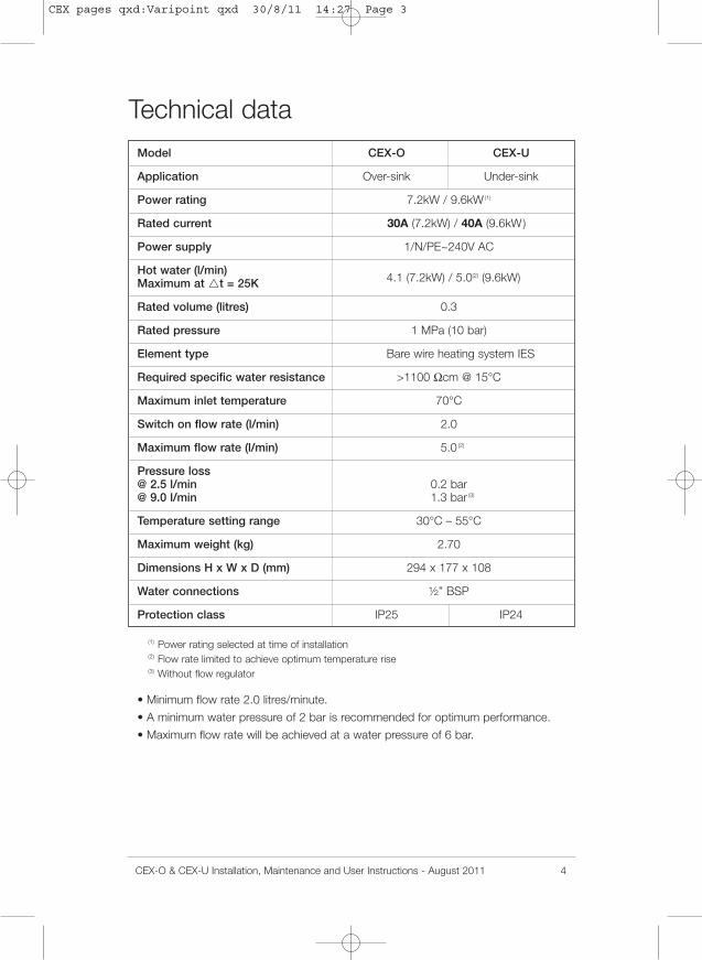
Technical dataModel CEX-O CEX-U
Application Over-sink Under-sink
Power rating 7.2kW / 9.6kW (1)
Rated current 30A (7.2kW) / 40A (9.6kW)
Power supply 1/N/PE~240V AC
Hot water (l/min)Maximum at �t = 25K 4.1 (7.2kW) / 5.0(2) (9.6kW)
Rated volume (litres) 0.3
Rated pressure 1 MPa (10 bar)
Element type Bare wire heating system IES
Required specific water resistance >1100 Ωcm @ 15°C
Maximum inlet temperature 70°C
Switch on flow rate (l/min) 2.0
Maximum flow rate (l/min) 5.0 (2)
Pressure loss@ 2.5 l/min 0.2 bar@ 9.0 l/min 1.3 bar (3)
Temperature setting range 30°C – 55°C
Maximum weight (kg) 2.70
Dimensions H x W x D (mm) 294 x 177 x 108
Water connections ½” BSP
Protection class IP25 IP24
(1) Power rating selected at time of installation(2) Flow rate limited to achieve optimum temperature rise(3) Without flow regulator
• Minimum flow rate 2.0 litres/minute.
• A minimum water pressure of 2 bar is recommended for optimum performance.
• Maximum flow rate will be achieved at a water pressure of 6 bar.
CEX-O & CEX-U Installation, Maintenance and User Instructions - August 2011 4
CEX pages qxd:Varipoint qxd 30/8/11 14:27 Page 3
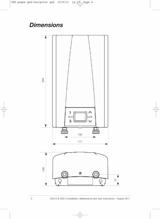
Dimensions
5 CEX-O & CEX-U Installation, Maintenance and User Instructions - August 2011
294
108
177
100
37
CEX pages qxd:Varipoint qxd 30/8/11 14:27 Page 4
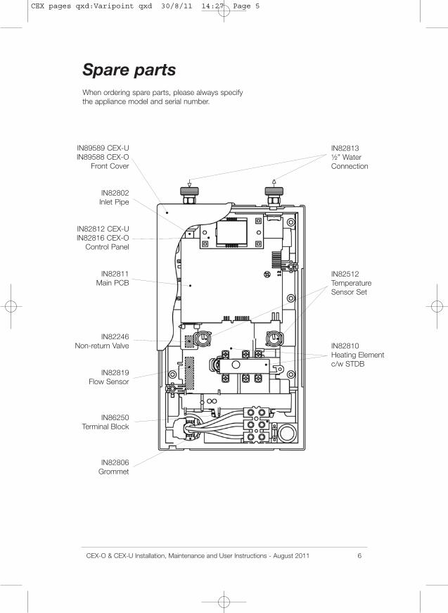
Spare partsWhen ordering spare parts, please always specifythe appliance model and serial number.
IN89589 CEX-UIN89588 CEX-O
Front Cover
IN82802Inlet Pipe
IN82812 CEX-UIN82816 CEX-O
Control Panel
IN82811Main PCB
IN82246Non-return Valve
IN82819Flow Sensor
IN86250Terminal Block
IN82806Grommet
IN82813½” WaterConnection
IN82512TemperatureSensor Set
IN82810Heating Elementc/w STDB
CEX-O & CEX-U Installation, Maintenance and User Instructions - August 2011 6
CEX pages qxd:Varipoint qxd 30/8/11 14:27 Page 5
InstallationRequirements• These instructions must be read and fully understood before commencing the
installation. If in doubt, or in need of further guidance please ring Zip on 0845 6024533.
• Zip InLine water heaters must be installed by a competent person familiar withelectric instantaneous water heaters.
• Installations must comply fully with UK Water Regulations and any Local Authorityrequirements.
• The electrical installation including earthing and cross bonding should comply withcurrent IEE regulations and any Local Authority requirements.
• Zip InLine water heaters must be installed according to the specification on the ratingplate and the technical specifications.
• The appliance must be permanently connected to the electrical supply through anisolation switch having a contact separation of at least 3mm on all poles.
• To protect the appliance, a circuit breaker must be fitted with a rating suitable for thenominal current of the appliance.
• The cross sectional area of the connection cable must be in accordance with thepower rating of the appliance and the specific requirements of the installation site upto a maximum cable size of 10mm2.
• Take care to protect the wiring from damage during installation and ensure that thewiring is not directly accessible after installation.
• Check that the power supply is switched off prior to electrical connection.
• This appliance must be earthed.
Installation site• The installation site must be free from frost at all times.
• The appliance is designed for wall mounted installation. CEX-O for over-sinkinstallation must be installed with the water connections downward. CEX-U forunder-sink installation must be installed with the water connections upward.
• The appliance complies with protection class IP25 for over-sink installation,protection class IP24 for under-sink installation and may therefore be installed inprotection zone 1.
• In order to minimise thermal losses, the distance between the appliance and theoutlet fitting should be as short as possible. Recommended maximum distance 2metres.
• For maintenance work a shut off valve should be installed in the water supply lineto he heater.
• Hot and cold water connecting pipes should be WRAS approved and of copperor steel construction. Plastic pipes may only be used if conforming to DIN 16893Series 2. The hot water pipes must be thermally insulated.
• The specific resistance of the supply water must be at least 1,100 Ωcm at 15°C.The specific resistance can be checked with the local water supply company.
7 CEX-O & CEX-U Installation, Maintenance and User Instructions - August 2011
CEX pages qxd:Varipoint qxd 30/8/11 14:27 Page 6
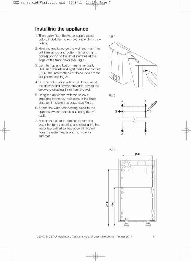
Fig 1
Fig 3
Fig 2
Installing the appliance1. Thoroughly flush the water supply pipes
before installation to remove any water bornedebris.
2. Hold the appliance on the wall and mark thedrill lines at top and bottom, left and right,corresponding to the small notches at theedge of the front cover (see Fig 1).
3. Join the top and bottom marks vertically(A-A) and the left and right marks horizontally(B-B). The intersections of these lines are thedrill points (see Fig 2).
4. Drill the holes using a 6mm drill then insertthe dowels and screws provided leaving thescrews protruding 5mm from the wall.
5. Hang the appliance with the screwsengaging in the key-hole slots in the backplate until it clicks into place (see Fig 3).
6. Attach the water connecting pipes to theappliance water connections using the ½”seals.
7. Ensure that all air is eliminated from thewater heater by opening and closing the hotwater tap until all air has been eliminatedfrom the water heater and no more airemerges.
CEX-O & CEX-U Installation, Maintenance and User Instructions - August 2011 8
CEX pages qxd:Varipoint qxd 30/8/11 14:27 Page 7
9 CEX-O & CEX-U Installation, Maintenance and User Instructions - August 2011
Fig 4
Fig 5
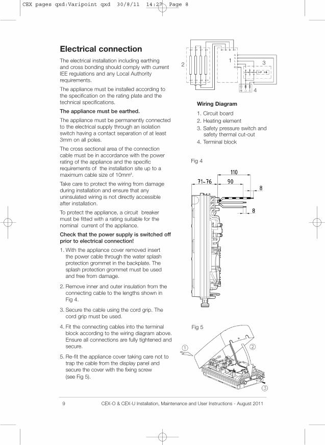
Electrical connectionThe electrical installation including earthingand cross bonding should comply with currentIEE regulations and any Local Authorityrequirements.
The appliance must be installed according tothe specification on the rating plate and thetechnical specifications.
The appliance must be earthed.
The appliance must be permanently connectedto the electrical supply through an isolationswitch having a contact separation of at least3mm on all poles.
The cross sectional area of the connectioncable must be in accordance with the powerrating of the appliance and the specificrequirements of the installation site up to amaximum cable size of 10mm2.
Take care to protect the wiring from damageduring installation and ensure that anyuninsulated wiring is not directly accessibleafter installation.
To protect the appliance, a circuit breakermust be fitted with a rating suitable for thenominal current of the appliance.
Check that the power supply is switched offprior to electrical connection!
1. With the appliance cover removed insertthe power cable through the water splashprotection grommet in the backplate. Thesplash protection grommet must be usedand free from damage.
2. Remove inner and outer insulation from theconnecting cable to the lengths shown inFig 4.
3. Secure the cable using the cord grip. Thecord grip must be used.
4. Fit the connecting cables into the terminalblock according to the wiring diagram above.Ensure all connections are fully tightened andsecure.
5. Re-fit the appliance cover taking care not totrap the cable from the display panel andsecure the cover with the fixing screw(see Fig 5).
Wiring Diagram
1. Circuit board2. Heating element3. Safety pressure switch and
safety thermal cut-out4. Terminal block
12 3
4
CEX pages qxd:Varipoint qxd 30/8/11 14:27 Page 8
CEX-O & CEX-U Installation, Maintenance and User Instructions - August 2011 10
Fig 6
Fig 7
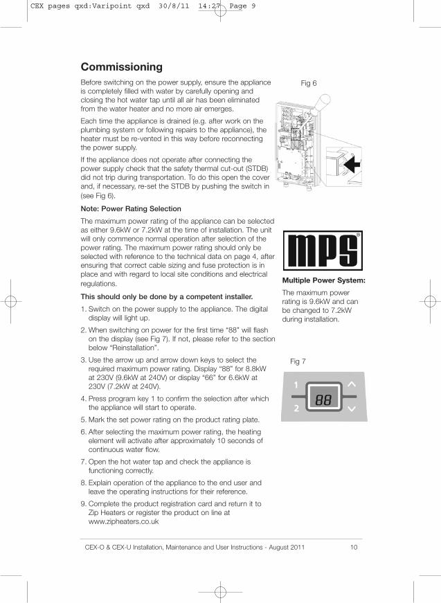
CommissioningBefore switching on the power supply, ensure the applianceis completely filled with water by carefully opening andclosing the hot water tap until all air has been eliminatedfrom the water heater and no more air emerges.
Each time the appliance is drained (e.g. after work on theplumbing system or following repairs to the appliance), theheater must be re-vented in this way before reconnectingthe power supply.
If the appliance does not operate after connecting thepower supply check that the safety thermal cut-out (STDB)did not trip during transportation. To do this open the coverand, if necessary, re-set the STDB by pushing the switch in(see Fig 6).
Note: Power Rating Selection
The maximum power rating of the appliance can be selectedas either 9.6kW or 7.2kW at the time of installation. The unitwill only commence normal operation after selection of thepower rating. The maximum power rating should only beselected with reference to the technical data on page 4, afterensuring that correct cable sizing and fuse protection is inplace and with regard to local site conditions and electricalregulations.
This should only be done by a competent installer.
1. Switch on the power supply to the appliance. The digitaldisplay will light up.
2. When switching on power for the first time “88” will flashon the display (see Fig 7). If not, please refer to the sectionbelow “Reinstallation”.
3. Use the arrow up and arrow down keys to select therequired maximum power rating. Display “88” for 8.8kWat 230V (9.6kW at 240V) or display “66” for 6.6kW at230V (7.2kW at 240V).
4. Press program key 1 to confirm the selection after whichthe appliance will start to operate.
5. Mark the set power rating on the product rating plate.
6. After selecting the maximum power rating, the heatingelement will activate after approximately 10 seconds ofcontinuous water flow.
7. Open the hot water tap and check the appliance isfunctioning correctly.
8. Explain operation of the appliance to the end user andleave the operating instructions for their reference.
9. Complete the product registration card and return it toZip Heaters or register the product on line atwww.zipheaters.co.uk
Multiple Power System:
The maximum powerrating is 9.6kW and canbe changed to 7.2kWduring installation.
CEX pages qxd:Varipoint qxd 30/8/11 14:27 Page 9
11 CEX-O & CEX-U Installation, Maintenance and User Instructions - August 2011
Fig 8
Fig 9
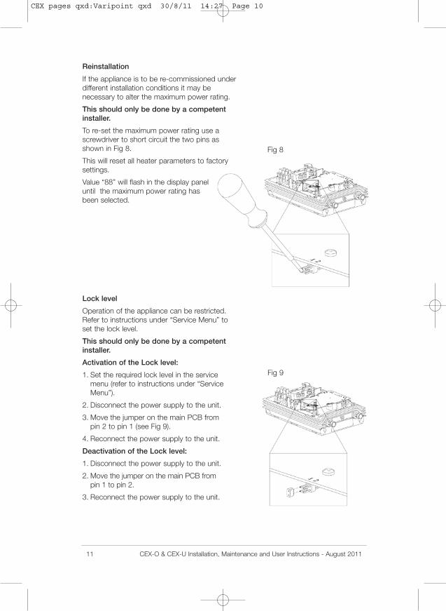
Reinstallation
If the appliance is to be re-commissioned underdifferent installation conditions it may benecessary to alter the maximum power rating.
This should only be done by a competentinstaller.
To re-set the maximum power rating use ascrewdriver to short circuit the two pins asshown in Fig 8.
This will reset all heater parameters to factorysettings.
Value “88” will flash in the display paneluntil the maximum power rating hasbeen selected.
Lock level
Operation of the appliance can be restricted.Refer to instructions under “Service Menu” toset the lock level.
This should only be done by a competentinstaller.
Activation of the Lock level:
1. Set the required lock level in the servicemenu (refer to instructions under “ServiceMenu”).
2. Disconnect the power supply to the unit.
3. Move the jumper on the main PCB frompin 2 to pin 1 (see Fig 9).
4. Reconnect the power supply to the unit.
Deactivation of the Lock level:
1. Disconnect the power supply to the unit.
2. Move the jumper on the main PCB frompin 1 to pin 2.
3. Reconnect the power supply to the unit.
CEX pages qxd:Varipoint qxd 30/8/11 14:27 Page 10
CEX-O & CEX-U Installation, Maintenance and User Instructions - August 2011 12
Fig 10
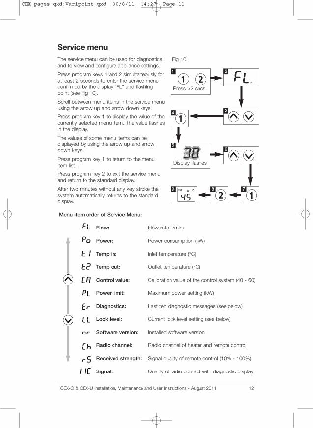
Service menuThe service menu can be used for diagnosticsand to view and configure appliance settings.
Press program keys 1 and 2 simultaneously forat least 2 seconds to enter the service menuconfirmed by the display “FL” and flashingpoint (see Fig 10).
Scroll between menu items in the service menuusing the arrow up and arrow down keys.
Press program key 1 to display the value of thecurrently selected menu item. The value flashesin the display.
The values of some menu items can bedisplayed by using the arrow up and arrowdown keys.
Press program key 1 to return to the menuitem list.
Press program key 2 to exit the service menuand return to the standard display.
After two minutes without any key stroke thesystem automatically returns to the standarddisplay.
Menu item order of Service Menu:
Flow: Flow rate (l/min)
Power: Power consumption (kW)
Temp in: Inlet temperature (°C)
Temp out: Outlet temperature (°C)
Control value: Calibration value of the control system (40 - 60)
Power limit: Maximum power setting (kW)
Diagnostics: Last ten diagnostic messages (see below)
Lock level: Current lock level setting (see below)
Software version: Installed software version
Radio channel: Radio channel of heater and remote control
Received strength: Signal quality of remote control (10% - 100%)
Signal: Quality of radio contact with diagnostic display
Press >2 secs
Display flashes
1 2
4
56
789
3
CEX pages qxd:Varipoint qxd 30/8/11 14:27 Page 11
13 CEX-O & CEX-U Installation, Maintenance and User Instructions - August 2011
“Er”: Diagnostics
The last ten diagnostic messages can bedisplayed.
Pressing program key 1 displays the currenterror code. A key explaining the error codescan be found inside the front cover of theappliance.
The arrow up and arrow down keys can beused to view the last ten error codes displayedin chronological order from “0” to “9” alongsidethe corresponding error code with “0” beingthe most recent.
“LL”: Lock level
The operating mode of the appliance can berestricted.
Setting options:
“0” no restriction (factory setting)
“1” disables “Reset to factory setting”.Parameters can be viewed but notmodified in service menu
“2” as “1”, additionally service menu cannotbe displayed
“3” as “2”, additionally program 1 and 2 settemperature values cannot be changed
“4” as “3”, additionally set temperature valueon appliance cannot be changed
Note: when lock level 1, 2, 3 or 4 is selectedthe system parameters cannot be modified inthe service menu.
In order to modify system parameters it isnecessary to remove the jumper from the mainPCB as described under “Deactivation of theLock level”.
CEX pages qxd:Varipoint qxd 30/8/11 14:27 Page 12
CEX-O & CEX-U Installation, Maintenance and User Instructions - August 2011 14
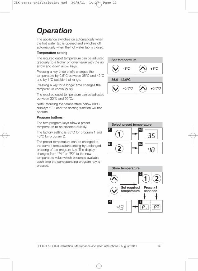
OperationThe appliance switches on automatically whenthe hot water tap is opened and switches offautomatically when the hot water tap is closed.
Temperature setting
The required outlet temperature can be adjustedgradually to a higher or lower value with the uparrow and down arrow keys.
Pressing a key once briefly changes thetemperature by 0.5°C between 35°C and 42°Cand by 1°C outside that range.
Pressing a key for a longer time changes thetemperature continuously.
The required outlet temperature can be adjustedbetween 30°C and 55°C.
Note: reducing the temperature below 30°Cdisplays “- -” and the heating function will notoperate.
Program buttons
The two program keys allow a presettemperature to be selected quickly.
The factory setting is 35°C for program 1 and48°C for program 2.
The preset temperature can be changed tothe current temperature setting by prolongedpressing of the program key. The displaychanges from “P1” or “P2” to the newtemperature value which becomes availableeach time the corresponding program key ispressed.
Set temperature
Store temperature
Set requiredtemperature
35.0 - 42.0ºC
-1ºC +1ºC
-0.5ºC +0.5ºC
Select preset temperature
Press >3seconds
1
A1 A2
B1 B2
2
4 3
CEX pages qxd:Varipoint qxd 30/8/11 14:27 Page 13
15 CEX-O & CEX-U Installation, Maintenance and User Instructions - August 2011
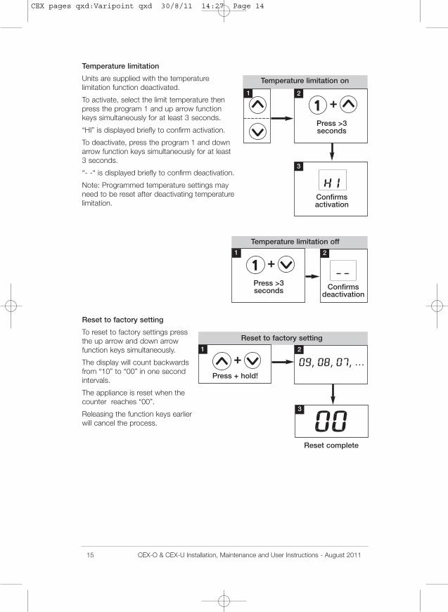
Temperature limitation
Units are supplied with the temperaturelimitation function deactivated.
To activate, select the limit temperature thenpress the program 1 and up arrow functionkeys simultaneously for at least 3 seconds.
“HI” is displayed briefly to confirm activation.
To deactivate, press the program 1 and downarrow function keys simultaneously for at least3 seconds.
“- -“ is displayed briefly to confirm deactivation.
Note: Programmed temperature settings mayneed to be reset after deactivating temperaturelimitation.
Reset to factory setting
To reset to factory settings pressthe up arrow and down arrowfunction keys simultaneously.
The display will count backwardsfrom “10” to “00” in one secondintervals.
The appliance is reset when thecounter reaches “00”.
Releasing the function keys earlierwill cancel the process.
Temperature limitation on
Temperature limitation off
Reset to factory setting
1 2
1 2
3
1 2
3
Confirmsactivation
Press >3seconds
Confirmsdeactivation
Press >3seconds
Press + hold!
Reset complete
CEX pages qxd:Varipoint qxd 30/8/11 14:27 Page 14
CEX-O & CEX-U Installation, Maintenance and User Instructions - August 2011 16
Energy saving
Set the required hot water temperature on theappliance.
If the water is too hot reduce the temperatureon the appliance instead of mixing with coldwater.
Adding cold water wastes valuable energy thathas been used producing excessively hot water.
Also, any cold water added is not controlledby the electronic circuitry meaning thatprecise temperature control can no longer beguaranteed when supplying more than oneoutlet.
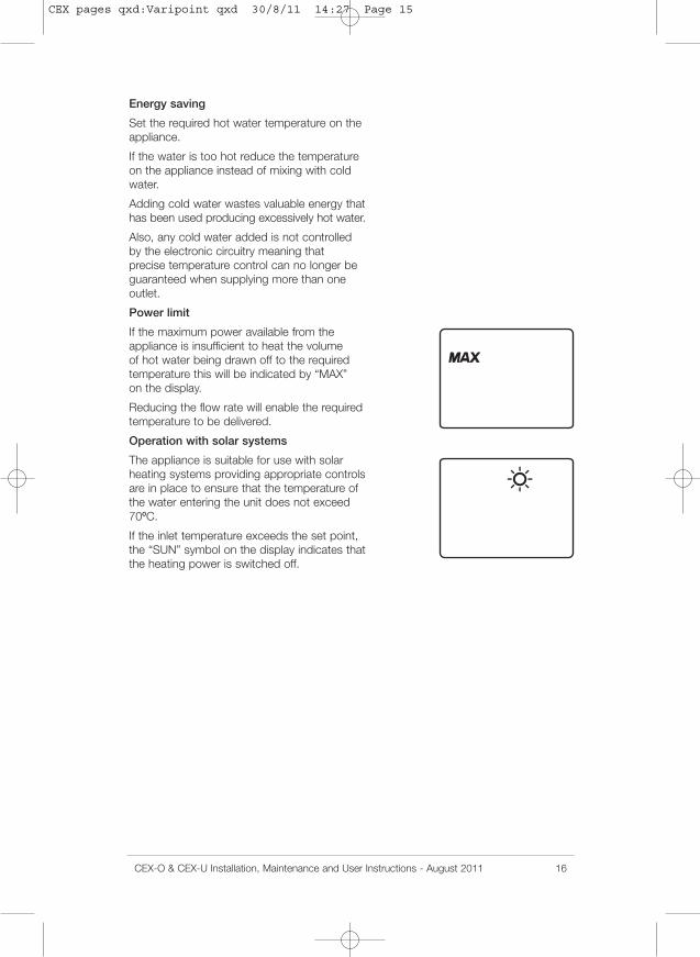
Power limit
If the maximum power available from theappliance is insufficient to heat the volumeof hot water being drawn off to the requiredtemperature this will be indicated by “MAX”on the display.
Reducing the flow rate will enable the requiredtemperature to be delivered.
Operation with solar systems
The appliance is suitable for use with solarheating systems providing appropriate controlsare in place to ensure that the temperature ofthe water entering the unit does not exceed70ºC.
If the inlet temperature exceeds the set point,the “SUN” symbol on the display indicates thatthe heating power is switched off.
CEX pages qxd:Varipoint qxd 30/8/11 14:27 Page 15
17 CEX-O & CEX-U Installation, Maintenance and User Instructions - August 2011
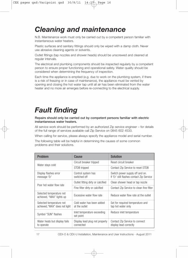
Problem Cause Solution
Water stays coldCircuit breaker tripped Reset circuit breaker
STDB tripped Contact Zip Service to reset STDB
Display flashes error Control system has Switch power supply off and on.message ‘Er’ switched off If ‘Er’ still flashes contact Zip Service
Poor hot water flow rateOutlet fitting dirty or calcified Clean shower head or tap nozzle
Fine filter dirty or calcified Contact Zip Service to clean fine filter
Selected temperature notachieved, “MAX” lights up Excessive water flow rate Reduce water flow rate at the outlet
Selected temperature not Cold water has been added Set for required temperature andachieved,“MAX” does not light at the outlet tap hot water only
Symbol “SUN” flashesInlet temperature exceeding Reduce inlet temperatureset point
Water heats but display fails Display lead plug not properly Contact Zip Service to connectto operate connected display lead correctly
Cleaning and maintenanceN.B. Maintenance work must only be carried out by a competent person familiar withinstantaneous water heaters.
Plastic surfaces and sanitary fittings should only be wiped with a damp cloth. Neveruse abrasive cleaning agents or solvents.
Outlet fittings (tap nozzles and shower heads) should be unscrewed and cleaned atregular intervals.
The electrical and plumbing components should be inspected regularly by a competentperson to ensure proper functioning and operational safety. Water quality should beconsidered when determining the frequency of inspection.
Each time the appliance is emptied (e.g. due to work on the plumbing system, if thereis a risk of freezing or in case of maintenance), the appliance must be vented byopening and closing the hot water tap until all air has been eliminated from the waterheater and no more air emerges before re-connecting to the electrical supply.
Fault findingRepairs should only be carried out by competent persons familiar with electricinstantaneous water heaters.
All service work should be performed by an authorized Zip service engineer – for detailsof the full range of services available call Zip Service on 0845 602 4533.
When calling for service, please always specify the appliance model and serial number.
The following table will be helpful in determining the causes of some commonproblems and their solutions.
CEX pages qxd:Varipoint qxd 30/8/11 14:27 Page 16