Embed Size (px)
Citation preview
2014 REV 01
COLT
ADV.IT
Cat
alog
ue M
KP 2
014
– Re
v. 0
1 - I
ssue
d on
Nov
201
3
ICAR S.p.A.Via Isonzo, 1020900 Monza (MB) - Italytel. +39 039 83.951fax +39 039 [email protected]
THE TECHNICAL CHARACTERISTICS AND THE CASE DIMENSIONS ARE NOT BINDING AND CAN BE MODIFIED WITHOUT NOTICE. ICAR DECLINES ANY RESPONSABILITY FOR DAMAGES TO OBJECTS OR PEOPLE DERIVING FROM UNSUITABLE USE OF ITS PRODUCTS.
AC ApplicationsMetallized Polypropylene
Self Healing
MKPMKPMKPSERIESSERIESSERIES
POWERELECTRONICSCAPACITORS
1
1. COMPANY PROFILE
OUR MISSION:
“Develop and supply high-quality capacitors, providing all the customers with full assistance from the design throughthe delivery. We will take care to any particular needs that the customer may have.”
Established in 1946, ICAR has rapidly reached, and since then maintained, a leadership position in the research anddevelopment of new capacitors and components of which capacitors are key parts.In the early 60’s, first in the world, ICAR started the production of metallized polypropylene film capacitors, bydeveloping the film metallization by its own.ICAR group nowadays controls all the manufacturing phases of the capacitor: from the polypropylene film extrusionthrough its metallization, to the production of the finished capacitor. The know-how accrued in almost 50 years ofmetallized film production, has enabled ICAR to bring to the market innovative products.Today ICAR Group is a leader in the production of capacitors, both for power electronics applications and for lowand medium voltage power factor correction.
ICAR Group today offers a wide range of products, all manufactured at its 6 plants located in Europe, that includes:
• power electronics and special capacitors• lighting capacitors• motor run capacitors• Power Factor Correction capacitors and Systems• L.V. and M.V. voltage stabilizers• transformers and chokes
MKP-MKP3P-SERIES 15-11-2010_6.qxp 24-01-2011 14:24 Pagina 4

2
2. ICAR GROUP PRODUCT RANGEPOWER ELECTRONICS AND SPECIAL CAPACITORS
Polypropylene film capacitors for:• DC link input filter both for industrial and traction inverters
(LNK series and BIOENERGY D series)• AC filter for inverters and UPS (MKV, MKP series)• snubber capacitors for semiconductors (THY and MKV series)• all purpose AC and DC capacitors (MKV, MKP and BIOENERGY A series)• medium frequency furnaces (BIOFURN Series) and medical application• special capacitors for energy storage
LIGHTING CAPACITORS
ICAR series of lighting capacitors are suitable for parallel and series power factor correction applicationsin both fluorescent and discharge light fittings.Moreover Plastic Case Type A and Metal Case Type B capacitors can be equipped with a wide range offixing devices and terminals options.ENEC and UL approvals certify that ICAR lighting capacitors are in compliance with the latest standardsand assures customers of an ICAR product with high levels of quality and reliability.
M.V. PFC CAPACITORS AND BANKS
Wide range of M.V. power capacitors, with powers from 50 to 800 kvar, available in single and three phaseversions, up to 24 kV rated voltage.Capacitor banks up to 150 kV both for indoor and outdoor installation can be supplied on customer need.
POWER CAPACITORS AND PFC CONTROLLERS
Aluminium can three phase capacitors of the CRT range are available for voltages from 230V to 800V andreactive powers ranging from 1 to 40 kvar.Power Factor Correction Controllers of 5 to 12 steps, enjoys features like incorporated temperature sensorsand control, alarms and protection functions.
MOTOR RUN CAPACITORS
ICAR motor run capacitor product range is one of the largest on the market.The polypropylene film capacitors are available for different levels of voltage from 250V up to 500V withlong life ratings up to 30.000 hours.The variety of terminations and fixings shown in our catalogue gives the possibility to use these capacitorsin any kind of application. The special design of ICAR capacitors distinguishes these components both fortheir quality and for their reliability.IMQ, VDE and UL approvals guarantee the ICAR motor capacitor range meets with international standards.
PFC SISTEMS AND HARMONIC FILTERS
Range is complete of fix and automatic LV power factor correction systems, standard and detuned, activeand passive harmonic absorption filters.All of automatic systems have undergone type tests at International Laboratories
MKP-MKP3P-SERIES 15-11-2010_6.qxp 24-01-2011 14:24 Pagina 5
3
3. QUALITY POLICY
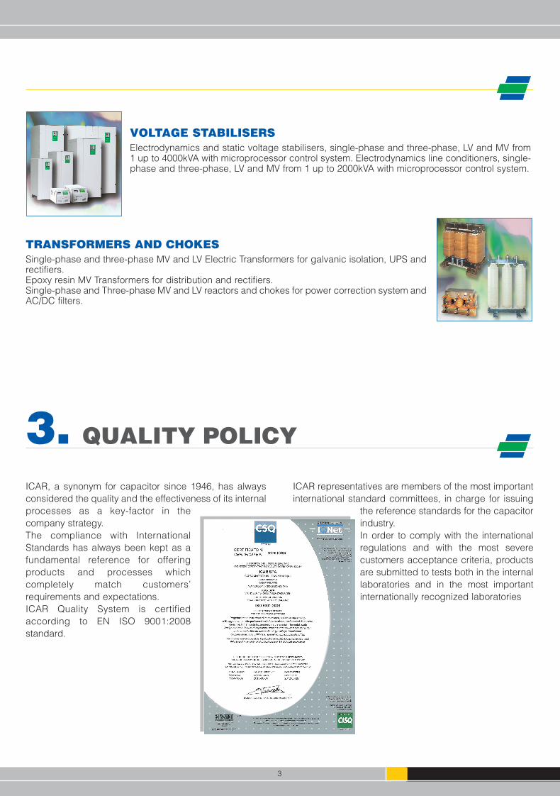
VOLTAGE STABILISERSElectrodynamics and static voltage stabilisers, single-phase and three-phase, LV and MV from1 up to 4000kVA with microprocessor control system. Electrodynamics line conditioners, single-phase and three-phase, LV and MV from 1 up to 2000kVA with microprocessor control system.
TRANSFORMERS AND CHOKESSingle-phase and three-phase MV and LV Electric Transformers for galvanic isolation, UPS andrectifiers.Epoxy resin MV Transformers for distribution and rectifiers.Single-phase and Three-phase MV and LV reactors and chokes for power correction system andAC/DC filters.
ICAR, a synonym for capacitor since 1946, has alwaysconsidered the quality and the effectiveness of its internalprocesses as a key-factor in thecompany strategy.The compliance with InternationalStandards has always been kept as afundamental reference for offeringproducts and processes whichcompletely match customers’requirements and expectations.ICAR Quality System is certifiedaccording to EN ISO 9001:2008standard.
ICAR representatives are members of the most importantinternational standard committees, in charge for issuing
the reference standards for the capacitorindustry.In order to comply with the internationalregulations and with the most severecustomers acceptance criteria, productsare submitted to tests both in the internallaboratories and in the most importantinternationally recognized laboratories
MKP-MKP3P-SERIES 15-11-2010_6.qxp 24-01-2011 14:24 Pagina 6

4
SELECTION RULES
VOLTAGE
Select a capacitor with surge peak voltage (US), rated voltage(UNDC) and rms voltage (Urms) higher than the operating ones.
Consider that the rated voltage UNDC shall be higher than the sumof the DC component and the repetitive peak of the ACcomponent.
It is possible, within certain limits, to work above the rated voltagebut this reduces the expected life of the capacitor.
During switching working condition, residual voltage before re-energizing shall not exceed 10% the rated voltage.
CURRENT AND FREQUENCY RANGE
Select a capacitor with maximum current Imax, higher than theoperating IRMS
Consider that: • a thermal check shall be performed in order to verify that the
chosen capacitor does not exceed the max operatingtemperature at operating IRMS
• the Imax of the capacitors has been calculated for a ϑh - ϑ0 ofabout 25°C and considering a voltage waveform composed by:
• a 50Hz fundamental with rms value Urms, having an impactboth on conduction losses (Pc) and dielectric losses (Q tanδ0)
• a voltage harmonics contents affecting only the conductionlosses (Pc).
Pc= RS * I2rms for MKP single phase cap.
Pc=3 * RS * I2rms for MKP-3P three phase cap.
In reality the harmonics content affects also the dielectric losses but this can be only evaluated starting from an estimated or measured harmonics spectrum.
THERMAL CHECKThe dissipated power consists of dielectric losses (Q tan δ0) dueto the polypropylene film and conduction losses (Pc) due to theresistance of the electrodes and the connections.
Consider that :the hot spot temperature can be estimated as follows:ϑh = Rth * P + ϑ0
the total dissipated power can be calculated as follows:P = Q tan δ0 + Pc
During stationary operation ϑh must not exceed 85°C. Power lossesshall be strongly reduced when operating at an ambienttemperature equal to 85°C. Please contact ICAR Tech. Dept. forderating according to ambient temperature.
At rated duty and hot spot temperature of 70°C the expectedlifetime is 100.000 hours with a statistical failure rate of 300FIT(97% survival).
WARNINGThe thermal check is based on the hypothesis that the heatgenerated into the capacitor is transmitted to the environmentthrough the case surface. Possible localised overheating (poorconnections, hot components in the nearby as other capacitors,operation with high harmonics frequency etc.) would bring thecapacitor to a dramatic failure or to a reduction of the expectedlife. Special tests by means of thermocouples should beconducted to be sure that the maximum hot spot temperature isnot exceeded even under the most critical ambient circumstances.
DEFINITIONS
CN Rated Capacitance measured at 20°C.Urms Rated rms voltageUN Maximum operating peak recurrent voltage of either
polarity of a reversing type waveform for which thecapacitor has been designed.
UNDC Maximum operating peak voltage of either polarity ofa non reversing type waveform for which thecapacitor has been designed for continuous operation.
US Surge (not repetitive) peak voltageUI Rated insulation voltage. Rms value of the AC voltage
for which the terminal to case insulation has beendesigned and tested.Unless stated otherwise, the rated insulation voltageshould be considered equal to the capacitor’s rated rms voltage.
IMAX Maximum rms current value for continuous operation. Its value depends on the ambient temperature.
Clearance Shortest distance in air between terminals conductingparts or between terminal and case
Creepage Shortest distance along an insulated surface betweenterminals conducting parts or between terminal andcase
Q Reactive power 2π x FN x C x U2
rms for MKP single phase cap.3 x 2π x FN x C x U2
rms for MKP-3P three phase cap.FN Fundamental frequencyRS Series resistance i.e. the resistance responsible for
the current heat losses (Pc) in the capacitor. tan δ0 Dielectric dissipation factor. It can be considered
constant in the normal working frequency range.Typical value for polypropylene is 2 x 10⁻⁴
dv/dt Maximum slope of the voltage waveformIPK Peak current IPK = C dV/dt.P Active power (losses)
Q x tanδ0 + RS x I2rms for MKP single phase cap.
Q x tanδ0 + 3 x RS x I2rms for MKP - 3P three phase cap.
Rth Thermal resistance between the hot-spot in the winding and the environment (natural cooling), so that:
P = (ϑh - ϑ0) / Rth
In case of forced air cooling the thermal resistancewill be reduced of 20%.
ϑh Hottest point in the capacitor winding = Rth x P+ϑ0
ϑ0 Operating ambient temperature. It is the air temperaturemeasured under steady conditions, with naturalconvection at 0,1m from the capacitor case and at two-thirds of the height from its base.
Tc Temperature coefficient of capacitance. Thecoefficient is equal to –260 ppm/°C
τc Time constant between terminals: it is the product ofinsulation resistance between terminals at 20°C andthe value of capacitance. The time constant betweenterminals for the MKP series is in general greaterthan 3000 s
Ha Maximum altitude. The max. altitude shall not exceed 2000m corresponding to 0.7 bar
Ln Expected life at rated voltage Urms and hot-spottemperature of 70°C
L Expected life at the actual working conditionsLS Self inductance of the capacitor. It is due to the
internal connections, terminals, winding characteristics and physical dimensions.
λ Failure rate (FIT) = 109 x failures/component x hour
4. SELECTION RULES AND DEFINITIONS
MKP-MKP3P-SERIES 15-11-2010_6.qxp 24-01-2011 14:24 Pagina 7
5
5. TECHNICAL INFORMATION
RatingsCapacitance tolerance: ±10%, other tolerances available on requestUseful life: 100.000hrs at 70°C hot-spot, Failure rate: 300FIT
ApplicationExpressly designed for AC applications. Single phase MKP capacitors may be used with dc voltage up to UNDC
Environmental conditionsOperating temperatureϑmin =-25°C, ϑmax =+85°C ϑmax temperature of the hottest point on the case at which the capacitor may operate.
For further indications see Selection Rules at par. 4;ϑmin minimum operating ambient temperature at which the capacitor may operate;Storage temperatureϑmin =-40°C, ϑmax =+85°C ϑmax maximum ambient temperature at which the capacitor may be continuously maintained non-operating;ϑmin minimum ambient temperature at which the capacitor may be continuously maintained non-operating;
Humidity classClass F. Max relative humidity 75% annual on average, 95% 30 days per year, condensation not permitted
DesignThe capacitor consists of metalized polypropylene windings filled with dry resin. This technology gives many advantages: - high AC voltage load capability
- high specific ratio capacitance to volume- high capability to withstand surge currents- very good self healig characteristics- no risk of oil or gas leakage- safe operation by means of an integrated overpessure disconnector
Case material and filler Case: aluminium Filler: resinLow smoke and toxicity emission in accordance to UNI CEI 11170-3 GUIDELINES FOR FIRE PROTECTION OF RAILWAY VEHICLES:ACCEPTABILITY LIMITS.
Environmental CompatibilityMKP series do not contain PCB and is manufactured in accordance to RohS restrictions
Protection against accidental contactMKP single phase capacitors are NOT protected against accidental contact.MKP -3P three phase capacitors are equiped with a touch proof screw terminals board rated IP20
DischargeAll the capacitors are NOT provided with internal/external discharge device
Assembly/CoolingThe useful life of a capacitor can be dramatically reduced if exposed to excessive heat. In general, an increase in the ambient tempera-ture of 5°C will halve the expected lifetime. Capacitors must be allowed to cool and should be shielded from external heat sources.Capacitors shall not be placed near to heat source and a minimum clearance of 20mm between the capacitors shall be maintained.
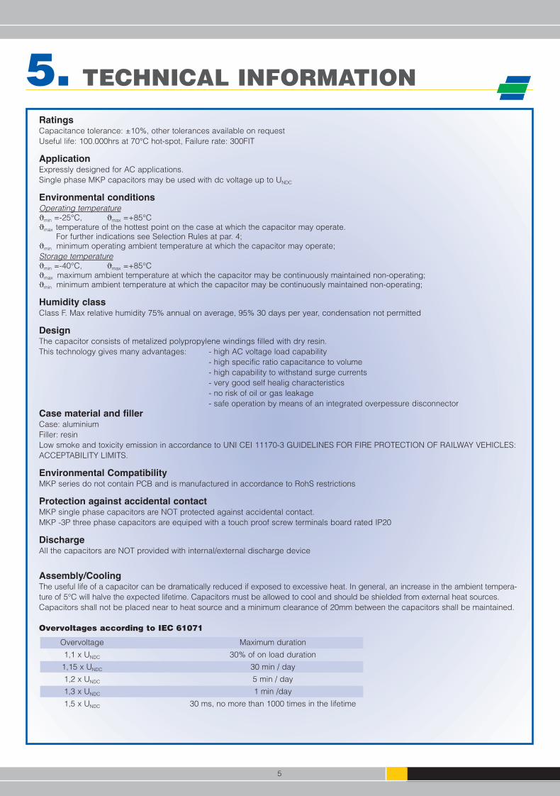
Overvoltages according to IEC 61071
Overvoltage Maximum duration
1,1 x UNDC 30% of on load duration
1,15 x UNDC 30 min / day
1,2 x UNDC 5 min / day
1,3 x UNDC 1 min /day
1,5 x UNDC 30 ms, no more than 1000 times in the lifetime
MKP-MKP3P-SERIES 15-11-2010_6.qxp 24-01-2011 14:24 Pagina 8
6
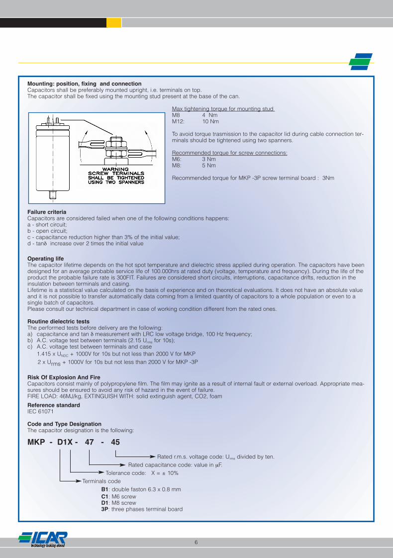
Mounting: position, fixing and connection Capacitors shall be preferably mounted upright, i.e. terminals on top.The capacitor shall be fixed using the mounting stud present at the base of the can.
Max tightening torque for mounting stud M8 4 Nm M12: 10 Nm
To avoid torque trasmission to the capacitor lid during cable connection ter-minals should be tightened using two spanners.
Recommended torque for screw connections:M6: 3 Nm M8: 5 Nm
Recommended torque for MKP -3P screw terminal board : 3Nm
Failure criteriaCapacitors are considered failed when one of the following conditions happens:a - short circuit;b - open circuit;c - capacitance reduction higher than 3% of the initial value;d - tanδ increase over 2 times the initial value
Operating lifeThe capacitor lifetime depends on the hot spot temperature and dielectric stress applied during operation. The capacitors have beendesigned for an average probable service life of 100.000hrs at rated duty (voltage, temperature and frequency). During the life of theproduct the probable failure rate is 300FIT. Failures are considered short circuits, interruptions, capacitance drifts, reduction in theinsulation between terminals and casing.Lifetime is a statistical value calculated on the basis of experience and on theoretical evaluations. It does not have an absolute valueand it is not possible to transfer automatically data coming from a limited quantity of capacitors to a whole population or even to asingle batch of capacitors. Please consult our technical department in case of working condition different from the rated ones.
Routine dielectric testsThe performed tests before delivery are the following:a) capacitance and tan δ measurement with LRC low voltage bridge, 100 Hz frequency;b) A.C. voltage test between terminals (2.15 Urms for 10s);c) A.C. voltage test between terminals and case
1.415 x UNDC + 1000V for 10s but not less than 2000 V for MKP2 x Urms + 1000V for 10s but not less than 2000 V for MKP -3P
Risk Of Explosion And FireCapacitors consist mainly of polypropylene film. The film may ignite as a result of internal fault or external overload. Appropriate mea-sures should be ensured to avoid any risk of hazard in the event of failure. FIRE LOAD: 46MJ/kg, EXTINGUISH WITH: solid extinguish agent, CO2, foam
Reference standardIEC 61071
Code and Type DesignationThe capacitor designation is the following:
MKP - D1X - 47 - 45
Rated r.m.s. voltage code: Urms divided by ten.Rated capacitance code: value in µF.
Tolerance code: X = ± 10% Terminals code
B1: double faston 6.3 x 0.8 mm C1: M6 screw D1: M8 screw3P: three phases terminal board
MKP-MKP3P-SERIES 15-11-2010_6.qxp 24-01-2011 14:24 Pagina 9
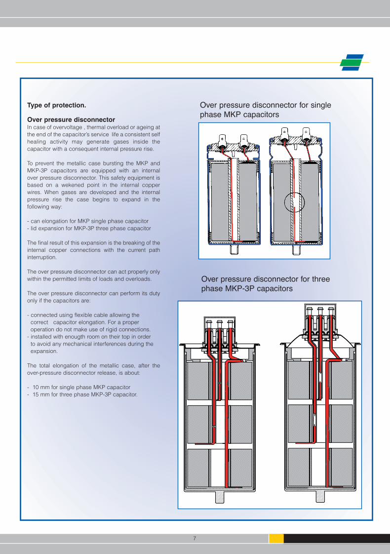
Type of protection.
Over pressure disconnectorIn case of overvoltage , thermal overload or ageing atthe end of the capacitor’s service life a consistent selfhealing activity may generate gases inside thecapacitor with a consequent internal pressure rise.
To prevent the metallic case bursting the MKP andMKP-3P capacitors are equipped with an internalover pressure disconnector. This safety equipment isbased on a wekened point in the internal copperwires. When gases are developed and the internalpressure rise the case begins to expand in thefollowing way:
- can elongation for MKP single phase capacitor- lid expansion for MKP-3P three phase capacitor
The final result of this expansion is the breaking of theinternal copper connections with the current pathinterruption.
The over pressure disconnector can act properly onlywithin the permitted limits of loads and overloads.
The over pressure disconnector can perform its dutyonly if the capacitors are:
- connected using flexible cable allowing thecorrect capacitor elongation. For a proper operation do not make use of rigid connections.
- installed with enougth room on their top in order to avoid any mechanical interferences during the expansion.
The total elongation of the metallic case, after theover-pressure disconnector release, is about:
- 10 mm for single phase MKP capacitor - 15 mm for three phase MKP-3P capacitor.
Over pressure disconnector for single phase MKP capacitors
Over pressure disconnector for three phase MKP-3P capacitors
7
MKP-MKP3P-SERIES 15-11-2010_6.qxp 24-01-2011 14:24 Pagina 10
MK
P-
...S
ing
le p
hase
AC
filte
r ca
pac
itors
Mo
de
lC
NU
ND
CU
SI M
AX
I PK
RS
Rth
LS
Fig
.∅∅
HW
eig
ht
Stu
dh
IC
reep
age
Cle
aran
ceP
cs
/B
ox
Bo
x
µFV
VA
rms
Am
Ω°C
/Wn
Hm
mm
mg
rm
mm
mm
mm
md
ime
ns
ion
s
MK
P-B
1X-2
0-30
2070
010
5012
350
9,5
16,7
701
3578
100
M8
10,0
13,4
86
8137
0x37
0x11
5M
KP
-B1X
-30-
3030
700
1050
1445
07,
714
,370
140
7813
0M
810
,013
,48
664
370x
370x
115
MK
P-B
1X-4
0-30
4070
010
5016
600
6,6
12,5
701
4578
160
M8
10,0
17,3
1210
4937
0x37
0x11
5M
KP
-B1X
-62,
5-30
62,5
700
1050
1695
05,
510
701
5578
230
M12
12,5
17,3
1210
3637
0x37
0x11
5M
KP
-B1X
-75-
3075
700
1050
1611
505,
19,
570
160
7827
0M
1212
,517
,312
1036
370x
370x
115
MK
P-B
1X-1
00-3
010
070
010
5016
950
7,1
8,5
901
5510
329
0M
1212
,517
,312
1036
370x
370x
161
MK
P-B
1X-1
20-3
012
070
010
5016
1150
6,5
8,2
901
6010
335
0M
1212
,517
,312
1036
370x
370x
161
MK
P-C
1X-4
0-30
4070
010
5020
600
4,3
11,5
802
4587
180
M8
10,0
18,0
1210
4937
0x37
0x13
1M
KP
-C1X
-62,
5-30
62,5
700
1050
2795
03,
19,
580
255
8725
0M
1212
,518
,016
1136
370x
370x
131
MK
P-D
1X-8
0-30
8070
010
5033
1200
2,2
8,5
803
6587
340
M12
12,5
24,0
2012
2537
0x37
0x13
1M
KP
-C1X
-100
-30
100
700
1050
2495
04,
28,
510
02
5511
232
0M
1212
,518
,016
1136
370x
370x
161
MK
P-D
1X-1
30-3
013
070
010
5028
1200
3,0
7,8
100
365
112
430
M12
12,5
24,0
2012
2537
0x37
0x16
1M
KP
-D1X
-210
-30
210
700
1050
3220
002,
17,
310
03
8011
264
0M
1216
,024
,026
1616
370x
370x
161
MK
P-D
1X-2
70-3
027
070
010
5045
4000
1,2
6,3
703
8014
485
0M
1216
,024
,026
1616
370x
370x
200
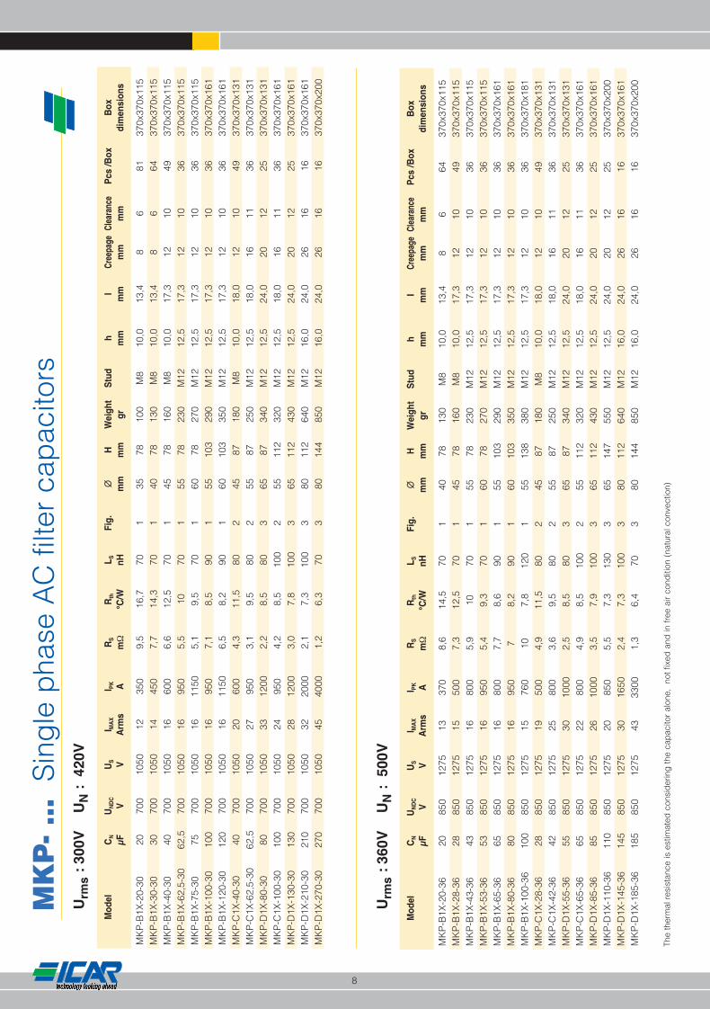
The
ther
mal
res
ista
nce
is e
stim
ated
con
sid
erin
g th
e ca
pac
itor
alon
e,
not f
ixed
and
in fr
ee a
ir co
nditi
on (
natu
ral c
onve
ctio
n)
Urm
s:
300V
UN
:42
0V
Mo
de
lC
NU
ND
CU
SI M
AX
I PK
RS
Rth
LS
Fig
.∅∅
HW
eig
ht
Stu
dh
IC
reep
age
Cle
aran
ceP
cs
/B
ox
Bo
x
µFV
VA
rms
Am
Ω°C
/Wn
Hm
mm
mg
rm
mm
mm
mm
md
ime
ns
ion
s
MK
P-B
1X-2
0-36
2085
012
7513
370
8,6
14,5
701
4078
130
M8
10,0
13,4
86
6437
0x37
0x11
5M
KP
-B1X
-28-
3628
850
1275
1550
07,
312
,570
145
7816
0M
810
,017
,312
1049
370x
370x
115
MK
P-B
1X-4
3-36
4385
012
7516
800
5,9
1070
155
7823
0M
1212
,517
,312
1036
370x
370x
115
MK
P-B
1X-5
3-36
5385
012
7516
950
5,4
9,3
701
6078
270
M12
12,5
17,3
1210
3637
0x37
0x11
5M
KP
-B1X
-65-
3665
850
1275
1680
07,
78,
690
155
103
290
M12
12,5
17,3
1210
3637
0x37
0x16
1M
KP
-B1X
-80-
3680
850
1275
1695
07
8,2
901
6010
335
0M
1212
,517
,312
1036
370x
370x
161
MK
P-B
1X-1
00-3
610
085
012
7515
760
107,
812
01
5513
838
0M
1212
,517
,312
1036
370x
370x
181
MK
P-C
1X-2
8-36
2885
012
7519
500
4,9
11,5
802
4587
180
M8
10,0
18,0
1210
4937
0x37
0x13
1M
KP
-C1X
-42-
3642
850
1275
2580
03,
69,
580
255
8725
0M
1212
,518
,016
1136
370x
370x
131
MK
P-D
1X-5
5-36
5585
012
7530
1000
2,5
8,5
803
6587
340
M12
12,5
24,0
2012
2537
0x37
0x13
1M
KP
-C1X
-65-
3665
850
1275
2280
04,
98,
510
02
5511
232
0M
1212
,518
,016
1136
370x
370x
161
MK
P-D
1X-8
5-36
8585
012
7526
1000
3,5
7,9
100
365
112
430
M12
12,5
24,0
2012
2537
0x37
0x16
1M
KP
-D1X
-110
-36
110
850
1275
2085
05,
57,
313
03
6514
755
0M
1212
,524
,020
1225
370x
370x
200
MK
P-D
1X-1
45-3
614
585
012
7530
1650
2,4
7,3
100
380
112
640
M12
16,0
24,0
2616
1637
0x37
0x16
1M
KP
-D1X
-185
-36
185
850
1275
4333
001,
36,
470
380
144
850
M12
16,0
24,0
2616
1637
0x37
0x20
0
Urm
s:
360V
UN
:50
0V
8
MKP-MKP3P-SERIES 15-11-2010_6.qxp 24-01-2011 14:24 Pagina 11
MK
P-
... S
ing
le p
hase
AC
filte
r ca
pac
itors
Mo
de
lC
NU
ND
CU
SI M
AX
I PK
RS
Rth
LS
Fig
.∅∅
HW
eig
ht
Stu
dh
IC
reep
age
Cle
aran
ceP
cs
/B
ox
Bo
x
µFV
VA
rms
Am
Ω°C
/Wn
Hm
mm
mg
rm
mm
mm
mm
md
ime
ns
ion
s
MK
P-B
1X-8
-48
811
0016
5010
200
1316
,770
135
7810
0M
810
,013
,48
681
370x
370x
115
MK
P-B
1X-1
1,5-
4811
,511
0016
5012
300
1014
,570
140
7813
0M
810
,013
,48
664
370x
370x
115
MK
P-B
1X-1
5-48
1511
0016
5014
360
8,6
12,5
701
4578
160
M8
10,0
17,3
1210
4937
0x37
0x11
5 M
KP
-B1X
-37-
4837
1100
1650
1656
09
8,6
901
5510
329
0M
1212
,517
,312
1036
370x
370x
161
MK
P-B
1X-4
5-48
4511
0016
5016
700
88,
290
160
103
350
M12
12,5
17,3
1210
3637
0x37
0x16
1 M
KP
-B1X
-55-
4855
1100
1650
1456
012
7,9
120
155
138
380
M12
12,5
17,3
1210
3637
0x37
0x18
1 M
KP
-B1X
-70-
4870
1100
1650
1470
010
7,7
120
160
138
450
M12
12,5
17,3
1210
3637
0x37
0x18
1 M
KP
-C1X
-24-
4824
1100
1650
2256
04,
49,
480
255
8725
0M
1212
,518
,016
1136
370x
370x
131
MK
P-D
1X-3
0-48
3011
0016
5028
750
3,2
8,4
803
6587
340
M12
12,5
24,0
2012
2537
0x37
0x13
1 M
KP
-C1X
-37-
4837
1100
1650
2056
06,
18,
310
02
5511
232
0M
1212
,518
,016
1136
370x
370x
161
MK
P-D
1X-4
8-48
4811
0016
5023
750
4,5
7,9
100
365
112
430
M12
12,5
24,0
2012
2537
0x37
0x16
1 M
KP
-D1X
-80-
4880
1100
1650
2712
503
7,3
100
380
112
640
M12
16,0
24,0
2616
1637
0x37
0x16
1 M
KP
-D1X
-100
-48
100
1100
1650
4024
501,
56,
370
380
144
850
M12
16,0
24,0
2616
1637
0x37
0x20
0 M
KP
-D1X
-160
-48
160
1100
1650
3624
502
5,1
803
8019
411
00M
1216
,024
,026
164
370x
370x
106
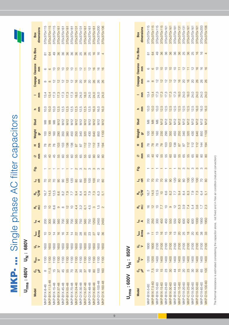
The
ther
mal
res
ista
nce
is e
stim
ated
con
sid
erin
g th
e ca
pac
itor
alon
e,
not f
ixed
and
in fr
ee a
ir co
nditi
on (
natu
ral c
onve
ctio
n)
Urm
s:
480V
UN
:68
0V
Mo
de
lC
NU
ND
CU
SI M
AX
I PK
RS
Rth
LS
Fig
.∅∅
HW
eig
ht
Stu
dh
IC
reep
age
Cle
aran
ceP
cs
/B
ox
Bo
x
µFV
VA
rms
Am
Ω°C
/Wn
Hm
mm
mg
rm
mm
mm
mm
md
ime
ns
ion
s
MK
P-B
1X-5
-60
512
0018
009
200
1616
,770
135
7810
0M
810
,013
,48
681
370x
370x
115
MK
P-B
1X-7
,5-6
07,
512
0018
0011
250
1214
,570
140
7813
0M
810
,013
,48
664
370x
370x
115
MK
P-B
1X-1
0-60
1014
0021
0013
300
1012
,570
145
7816
0M
810
,017
,312
1049
370x
370x
115
MK
P-B
1X-1
5-60
1514
0021
0016
450
7,7
1070
155
7823
0M
1212
,517
,312
1036
370x
370x
115
MK
P-B
1X-2
3-60
2314
0021
0015
450
108,
690
155
103
290
M12
12,5
17,3
1210
3637
0x37
0x16
1M
KP
-B1X
-30-
6030
1400
2100
1655
09
8,2
901
6010
335
0M
1212
,517
,312
1036
370x
370x
161
MK
P-B
1X-4
4-60
4414
0021
0013
550
127,
712
01
6013
845
0M
1212
,517
,312
1036
370x
370x
181
MK
P-C
1X-1
5-60
1514
0021
0020
450
5,3
9,4
802
5587
250
M12
12,5
18,0
1611
3637
0x37
0x13
1M
KP
-D1X
-20-
6020
1400
2100
2560
03,
98,
480
365
8734
0M
1212
,524
,020
1225
370x
370x
131
MK
P-C
1X-2
3-60
2314
0021
0018
450
7,4
8,3
100
255
112
320
M12
12,5
18,0
1611
3637
0x37
0x16
1M
KP
-D1X
-30-
6030
1400
2100
2060
05,
47,
910
03
6511
243
0M
1212
,524
,020
1225
370x
370x
161
MK
P-D
1X-5
0-60
5014
0021
0025
1000
3,6
7,3
100
380
112
640
M12
16,0
24,0
2616
1637
0x37
0x16
1M
KP
-D1X
-65-
6065
1400
2100
3819
501,
76,
470
380
144
850
M12
16,0
24,0
2616
1637
0x37
0x20
0M
KP
-D1X
-100
-60
100
1400
2100
3319
502,
35,
180
380
194
1100
M12
16,0
24,0
2616
437
0x37
0x10
6
Urm
s:
600V
UN
:85
0V
9
MKP-MKP3P-SERIES 15-11-2010_6.qxp 24-01-2011 14:24 Pagina 12

MK
P -
… S
ing
le p
hase
AC
filte
r ca
pac
itors
Mo
de
lC
NU
ND
CU
SI M
AX
I PK
RS
Rth
LS
Fig
.∅∅
HW
eig
ht
Stu
dh
IC
reep
age
Cle
aran
ceP
cs
/Bo
xB
ox
µFV
VA
rms
Am
Ω°C
/Wn
Hm
mm
mg
rm
mm
mm
mm
md
ime
ns
ion
s
MK
P-B
1X-3
,2-7
53,
212
0018
0012
300
8,7
16,7
701
3578
100
M8
10,0
13,4
86
8137
0x37
0x11
5M
KP
-B1X
-4,5
-75
4,5
1200
1800
1438
07,
114
,570
140
7813
0M
810
,013
,48
664
370x
370x
115
MK
P-B
1X-6
-75
614
0021
0016
500
6,2
12,5
701
4578
160
M8
10,0
17,3
1210
4937
0x37
0x11
5M
KP
-B1X
-9,5
-75
9,5
1400
2100
1680
05,
210
701
5578
230
M12
12,5
17,3
1210
3637
0x37
0x11
5M
KP
-B1X
-12-
7512
1400
2100
1695
04,
99,
370
160
7827
0M
1212
,517
,312
1036
370x
370x
115
MK
P-B
1X-1
9-75
1914
0021
0016
950
6,3
8,2
901
6010
335
0M
1212
,517
,312
1036
370x
370x
161
MK
P-C
1X-6
-75
614
0021
0022
500
3,8
11,5
802
4587
180
M8
10,0
18,0
1210
4937
0x37
0x13
1M
KP
-C1X
-9,5
-75
9,5
1700
2550
2880
02,
99,
480
255
8725
0M
1212
,518
,016
1136
370x
370x
131
MK
P-D
1X-1
2-75
1217
0025
5035
1000
28,
480
365
8734
0M
1212
,524
,020
1225
370x
370x
131
MK
P-C
1X-1
5-75
1517
0025
5024
800
48,
310
02
5511
232
0M
1212
,518
,016
1136
370x
370x
161
MK
P-D
1X-2
0-75
2017
0025
5028
1000
2,8
7,9
100
365
112
430
M12
12,5
24,0
2012
2537
0x37
0x16
1M
KP
-D1X
-32-
7532
1700
2550
3416
502
7,3
100
380
112
640
M12
16,0
24,0
2616
1637
0x37
0x16
1M
KP
-D1X
-40-
7540
1700
2550
4733
001,
16,
370
380
144
850
M12
16,0
24,0
2616
1637
0x37
0x20
0M
KP
-D1X
-65-
7565
1700
2550
4233
001,
55,
180
380
194
1100
M12
16,0
24,0
2616
437
0x37
0x10
6
The
ther
mal
res
ista
nce
is e
stim
ated
con
sid
erin
g th
e ca
pac
itor
alon
e,
not f
ixed
and
in fr
ee a
ir co
nditi
on (
natu
ral c
onve
ctio
n)
Urm
s:
750V
UN
:10
60V
Mo
de
lC
NU
ND
CU
SI M
AX
I PK
RS
Rth
LS
Fig
.∅∅
HW
eig
ht
Stu
dh
IC
reep
age
Cle
aran
ceP
cs
/Bo
xB
ox
µFV
VA
rms
Am
Ω°C
/Wn
Hm
mm
mg
rm
mm
mm
mm
md
ime
ns
ion
s
MK
P-B
1X-2
,3-8
52,
312
0018
0012
250
9,6
16,7
701
3578
100
M8
10,0
13,4
86
8137
0x37
0x11
5M
KP
-B1X
-3,3
-85
3,3
1200
1800
1435
07,
814
,570
140
7813
0M
810
,013
,48
664
370x
370x
115
MK
P-B
1X-7
-85
714
0021
0016
450
9,1
1090
145
103
200
M8
10,0
17,3
1210
4937
0x37
0x16
1M
KP
-B1X
-8,5
-85
8,5
1400
2100
1685
05,
19,
370
160
7827
0M
1212
,517
,312
1036
370x
370x
115
MK
P-B
1X-1
1-85
1114
0021
0016
660
7,3
8,6
901
5510
329
0M
1212
,517
,312
1036
370x
370x
161
MK
P-B
1X-1
3,5-
8513
,514
0021
0016
850
6,7
8,2
901
6010
335
0M
1212
,517
,312
1036
370x
370x
161
MK
P-C
1X-4
,5-8
54,
514
0021
0020
450
4,3
11,5
802
4587
170
M8
10,0
18,0
1210
4937
0x37
0x13
1M
KP
-C1X
-7-8
57
2000
3000
2766
03,
29,
480
255
8725
0M
1212
,518
,016
1136
370x
370x
131
MK
P-C
1X-1
1-85
1120
0030
0024
660
4,5
8,3
100
255
112
320
M12
12,5
18,0
1611
3637
0x37
0x16
1M
KP
-D1X
-14-
8514
2000
3000
2885
03,
27,
910
03
6511
243
0M
1212
,524
,020
1225
370x
370x
161
MK
P-D
1X-2
4-85
2420
0030
0033
1450
2,2
7,3
100
380
112
640
M12
16,0
24,0
2616
1637
0x37
0x16
1M
KP
-D1X
-30-
8530
2000
3000
4729
001,
26,
370
380
144
850
M12
16,0
24,0
2616
1637
0x37
0x20
0M
KP
-D1X
-47-
8547
2000
3000
4229
001,
65,
180
380
194
1100
M12
16,0
24,0
2616
437
0x37
0x10
6
Urm
s:
850V
UN
:12
00V
10
MKP-MKP3P-SERIES 15-11-2010_6.qxp 24-01-2011 14:24 Pagina 13
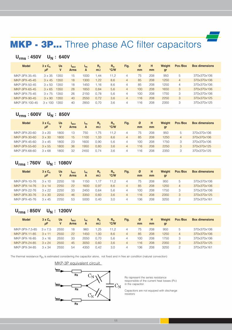
MKP - 3P… Three phase AC filter capacitors
Model 3 x CN Us IMAX IPK RS Rth Fig. Ø H Weight Pcs /Box Box dimensions
µF V Arms A mΩ °C/W mm mm gr
MKP-3PX-35-45 3 x 35 1350 15 1000 1,44 11,2 4 75 208 950 5 370x370x106MKP-3PX-45-45 3 x 45 1350 18 1300 1,22 8,6 4 85 208 1250 4 370x370x106MKP-3PX-50-45 3 x 50 1350 18 1450 1,16 8,6 4 85 208 1250 4 370x370x106MKP-3PX-65-45 3 x 65 1350 28 1850 0,84 5,6 4 100 208 1650 3 370x370x106MKP-3PX-75-45 3 x 75 1350 26 2150 0,78 5,6 4 100 208 1750 3 370x370x106MKP-3PX-90-45 3 x 90 1350 40 2550 0,72 3,6 4 116 208 2250 3 370x370x125MKP-3PX-100-45 3 x 100 1350 40 2850 0,70 3,6 4 116 208 2350 3 370x370x125
Urms : 450V UN : 640V
Model 3 x CN Us IMAX IPK RS Rth Fig. Ø H Weight Pcs /Box Box dimensions
µF V Arms A mΩ °C/W mm mm gr
MKP-3PX-20-60 3 x 20 1800 13 750 1,75 11,2 4 75 208 950 5 370x370x106MKP-3PX-30-60 3 x 30 1800 15 1100 1,33 8,6 4 85 208 1250 4 370x370x106MKP-3PX-45-60 3 x 45 1800 23 1600 0,90 5,6 4 100 208 1750 3 370x370x106MKP-3PX-55-60 3 x 55 1800 36 1950 0,80 3,6 4 116 208 2250 3 370x370x125MKP-3PX-68-60 3 x 68 1800 32 2450 0,74 3,6 4 116 208 2350 3 370x370x125
Urms : 600V UN : 850V
Model 3 x CN Us IMAX IPK RS Rth Fig. Ø H Weight Pcs /Box Box dimensions
µF V Arms A mΩ °C/W mm mm gr
MKP-3PX-10-76 3 x 10 2250 18 1150 1,17 11,2 4 75 208 950 5 370x370x106MKP-3PX-14-76 3 x 14 2250 22 1600 0,97 8,6 4 85 208 1250 4 370x370x106MKP-3PX-22-76 3 x 22 2250 33 2450 0,64 5,6 4 100 208 1750 3 370x370x106MKP-3PX-30-76 3 x 30 2250 46 3350 0,60 3,6 4 116 208 2350 3 370x370x125MKP-3PX-45-76 3 x 45 2250 53 5000 0,40 3,0 4 136 208 3250 2 370x370x161
Urms : 760V UN : 1080V
Model 3 x CN Us IMAX IPK RS Rth Fig. Ø H Weight Pcs /Box Box dimensions
µF V Arms A mΩ °C/W mm mm gr
MKP-3PX-7,5-85 3 x 7,5 2550 18 960 1,25 11,2 4 75 208 950 5 370x370x106MKP-3PX-11-85 3 x 11 2550 22 1450 1,00 8,6 4 85 208 1250 4 370x370x106MKP-3PX-16-85 3 x 16 2550 33 2050 0,70 5,6 4 100 208 1750 3 370x370x106MKP-3PX-24-85 3 x 24 2550 45 3050 0,60 3,6 4 116 208 2350 3 370x370x125MKP-3PX-34-85 3 x 34 2550 54 4350 0,42 3,0 4 136 208 3250 2 370x370x161
Urms : 850V UN : 1200V
The thermal resistance Rth is estimated considering the capacitor alone, not fixed and in free air condition (natural convection)
Rs rapresent the series resistanceresponsible of the current heat losses (Pc)in the capacitor.
Capacitors are not equiped with dischargeresistors
MKP-3P equivalent circuit.
11
MKP-MKP3P-SERIES 15-11-2010_6.qxp 24-01-2011 14:24 Pagina 14
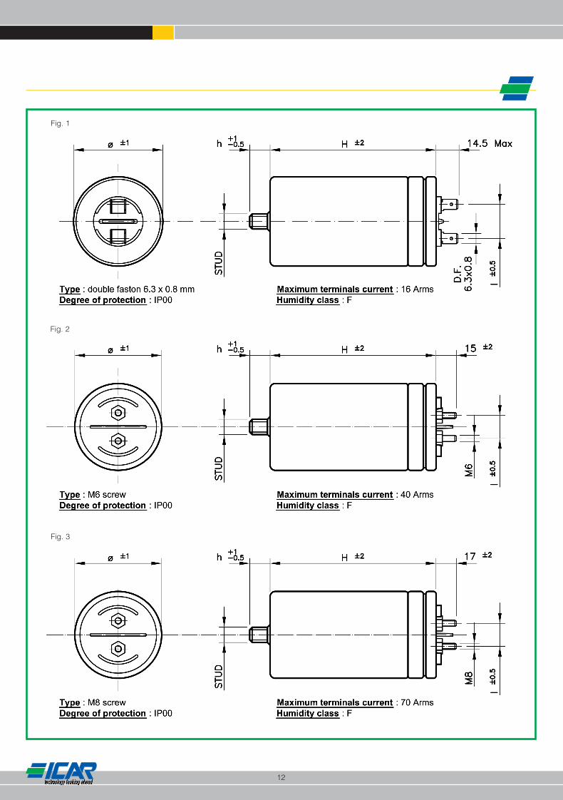
Fig. 1
Fig. 2
Fig. 3
12
MKP-MKP3P-SERIES 15-11-2010_6.qxp 24-01-2011 14:24 Pagina 15
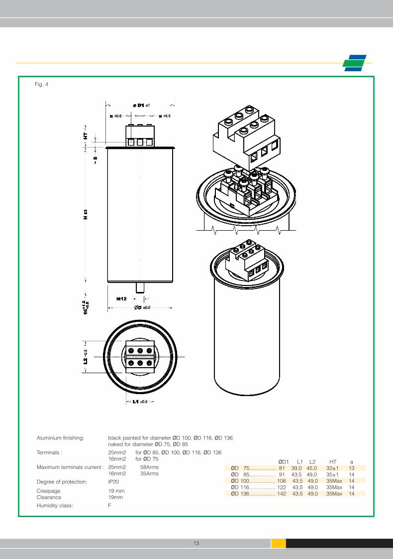
Aluminium finishing: black painted for diameter ØD 100, ØD 116, ØD 136.naked for diameter ØD 75, ØD 85
Terminals : 25mm2 for ØD 85, ØD 100, ØD 116, ØD 13616mm2 for ØD 75
Maximum terminals current : 25mm2 58Arms 16mm2 35Arms
Degree of protection: IP20
Creepage 19 mmClearance 19mm
Humidity class: F
Fig. 4
ØD1 L1 L2 HT a ØD 75.................. 81 39,0 45,0 32±1 13 ØD 85.................. 91 43,5 49,0 35±1 14 ØD 100.................. 106 43,5 49,0 35Max 14 ØD 116.................. 122 43,5 49,0 35Max 14 ØD 136.................. 142 43,5 49,0 35Max 14
13
MKP-MKP3P-SERIES 15-11-2010_6.qxp 24-01-2011 14:24 Pagina 16

WARNINGDO NOT MISAPPLY CAPACITORS FOR POWER ELECTRONICS
Icar is not responsible for any kind of possible damages to persons or things, derived from the improper installation and applicationof Power Electronics capacitors
Most common misapplication forms:
• Ripple current and peak current beyond specification or not according with the maximum power that can be dissipated.• Surge or working voltage beyond specified value.• Hot spot or storage temperature beyond the specified limits or not according with the maximum power that can be dissipated. • Incorrect mounting or wrong installation
– installation nearby hot components or heat sources– not suitable connections (not adequate cable or busbars cross section) – nuts and washers material, shape or size not suitable for the application– tightening torque not according to the specification
• Unusual service conditions as:– mechanical shock and vibrations,– corrosive or abrasive conductive parts in cooling air,– oil or water vapour or corrosive substances,– explosive gas or dust,– radioactivity,– excessive and fast variations of ambient conditions,– service areas higher than 2000 m above sea level.
Periodic check of the connection conditions and tightening torque is strongly recommended.
In case of doubt in choice or in performances of the capacitors Icar technical service MUST be contacted.
DISCLAIMER
All the information and data shown in this catalogue are not binding and can be modified without notice. Contact ICAR sales depar-tment to get updated specifications.Reliability data quoted by ICAR are based on statistical evaluations, and does not guarantee properties or performance of each sin-gle component.
All the products described in the catalogue shall be used within the limits stated in the technical specifications, nevertheless it isunderstood that a failure or an abnormal operation, even when capacitors are working within the specified limits, cannot be comple-tely excluded or foreseen at the current state of the art of technology.
Capacitors may become hazardous. Most common risks are related to combustible gas generation, explosion, fire, electrocution orabnormal operation of the capacitor. Not all the possible risks and safety measures are mentioned in this catalogue, further informa-tion are available on request.It is on customer responsibility to select and take all the necessary safety measures in his applications in order to avoid any possiblepersonal injury or property damage related to the use of capacitors. This is valid in particular for applications in which a failure or anabnormal operation of the capacitors could put at risk human life or health.ICAR SpA and all the persons acting on its behalf, disclaim any and all liabilities for possible damages resulting from the use of theproducts described in this catalogue or in any other publication.
ICAR reserves the right to discontinue the production of any item without notice.
All orders are subject to ICAR General Conditions of sales – latest revision
14
MKP-MKP3P-SERIES 15-11-2010_6.qxp 24-01-2011 14:24 Pagina 17

2014 REV 01
COLT
ADV.IT
Cat
alog
ue M
KP 2
014
– Re
v. 0
1 - I
ssue
d on
Nov
201
3
ICAR S.p.A.Via Isonzo, 1020900 Monza (MB) - Italytel. +39 039 83.951fax +39 039 [email protected]
THE TECHNICAL CHARACTERISTICS AND THE CASE DIMENSIONS ARE NOT BINDING AND CAN BE MODIFIED WITHOUT NOTICE. ICAR DECLINES ANY RESPONSABILITY FOR DAMAGES TO OBJECTS OR PEOPLE DERIVING FROM UNSUITABLE USE OF ITS PRODUCTS.
AC ApplicationsMetallized Polypropylene
Self Healing
POWERELECTRONICSCAPACITORS