Embed Size (px)
Citation preview

8/8/2019 Electronics May03
http://slidepdf.com/reader/full/electronics-may03 1/49
High-speed backplane interconnect
Vladimir Stojanovic
(with slides from J. Zerbe, P. Desai, R. Kollipara)

8/8/2019 Electronics May03
http://slidepdf.com/reader/full/electronics-may03 2/49
Outline
Inside the router
Backplane channel problem
What can backplane designer do about it
What can IC designer do about it
Scaling the system to 10-100Tb/s

8/8/2019 Electronics May03
http://slidepdf.com/reader/full/electronics-may03 3/49
Inside the Router
MAC
MAC
TM/Fabric
IF
TM/
Fabric
IF
NPU
NPU
SerDes
SerDes
Optics
OpticsSerDes
SerDes
SerDes
SerDes
Crossbar
Crossbar
Line Cards:8 to 16 per System
Switch Cards:2 to 4 per System
Passive
Backplane
M E M
M E M
M E M
M E M
M E M
M E M
M E M
M E M
Past OC-12
622 MHz LVDSparallel
GigE
1.25 Gbps serial
Present OC48
2.5 Gbps serial
10GigE
XAUI (3.125 Gbps) serial

8/8/2019 Electronics May03
http://slidepdf.com/reader/full/electronics-may03 4/49
OpticsMAC/
Framer
NPU/
TM
Switch
Fabric IF
XAUI
4, 3.125 Gbps
Serial Links
SPI4.2 CSIX
ProprietaryBackplane
8 to 16
of 1-3.2Gbps
Serial Links
Line Card:
Switch Card:32 to 64
Backplane
Serial Links
(1-3.2 Gbps)
Switch
Crossbar
IC
Serial Links in Networking Systems

8/8/2019 Electronics May03
http://slidepdf.com/reader/full/electronics-may03 5/49
Backplane interconnect path
Backplane via
Backplane connector
Line card
trace
PackageChip
Line card
viaBackplane trace
Packageto board
transition
There are many components on the signal path,
potential source of problems

8/8/2019 Electronics May03
http://slidepdf.com/reader/full/electronics-may03 6/49
RaSer X Link Features
PLLPLL
SerializerSerializer Tx Link
20 bit
ParallelInterface
1-10 Gbps
RefClk
Tx
Eq
Deserializer andDeserializer and
CDRCDR
Rx Link
1-10 Gbps
Rx
Eq
20 bit
Parallel
Interface
TX
RX
PLL
Process 0.13µ CMOS
Power 40mW / Gb
Area 1mm2
2-PAM Range 2 – 6.4 Gb/s
4-PAM Range 5 – 10 Gb/s

8/8/2019 Electronics May03
http://slidepdf.com/reader/full/electronics-may03 7/49
Impedance-controlled (CML) I/Os
Integrated terminations
Adjustable output-voltage/common mode
I/O Driver Scheme (Example)
50 Ω 50 ΩVtt
Zo = 50 Ω
Zo = 50 Ω RxTx
Vtt

8/8/2019 Electronics May03
http://slidepdf.com/reader/full/electronics-may03 8/49
System Issues
Goal – Increase Router Throughput
Limitations
Backplane channel
Power
Mechanical/Physical density constraints
Backplane and linecard routing density
Connector pin density
Package I/O density

8/8/2019 Electronics May03
http://slidepdf.com/reader/full/electronics-may03 9/49
Outline
Inside the router
Backplane channel problem
What can backplane designer do about it
What can IC designer do about it
Scaling the system to 10-100Tb/s

8/8/2019 Electronics May03
http://slidepdf.com/reader/full/electronics-may03 10/49
Backplane Component Effects
PCB only
PCB + Connectors
PCB, Connectors,
Via stubs & Devices

8/8/2019 Electronics May03
http://slidepdf.com/reader/full/electronics-may03 11/49
Deterministic Noise
0 2 4 6 8 10
-60
-50
-40
-30
-20
-10
0
frequency [GHz]
A t t e n u a t i o n [ d
B ]
FEXT
NEXT
THROUGH
0 1 2 3
0
0.2
0.4
0.6
0.8
1
ns
p u
s e r e s p o n s e
Tsymbol=160ps
Inter-symbol interference Dispersion (skin-effect, dielectric loss) - short latency
Reflections (impedance mismatches – connectors, via stubs,
device parasitics, package) – long latency

8/8/2019 Electronics May03
http://slidepdf.com/reader/full/electronics-may03 12/49
XTALK and reflections
Far-end XTALK (FEXT)
Desired signal
Near-end XTALK (NEXT)
Reflections
Primary reflection sources are at the connector/backplane
transition
Grouped in time – as a function of backplane length

8/8/2019 Electronics May03
http://slidepdf.com/reader/full/electronics-may03 13/49
Backplane channel variations
0 2 4 6 8 10
-60
-50
-40
-30
-20
-10
0
frequency [GHz]
A t t e n u a t i o n [
d B ]
9" FR4,via stub
26" FR4,via stub
26" FR4
9" FR4
Variability in trace length, routing layer and via stub
Significantly different transfer functions even within the same backplane

8/8/2019 Electronics May03
http://slidepdf.com/reader/full/electronics-may03 14/49
Test Backplane Example
Dielectric material FR-4 Nelco Roger
6000 4350
Dielectric constant 4.2 4 3.6
Loss tangent (1 MHz) 0.016 0.005 0.0035
Loss tangent (1 GHz) 0.017 0.007 0.0035
Thickness 0.295" 0.299" 0.297"
FR4 Cross Section
Trace lengths: 1.5”, 9”, 14”, 20” and 32”
Effective number of signal layers: 13
Effective number of total layers: 28

8/8/2019 Electronics May03
http://slidepdf.com/reader/full/electronics-may03 15/49
Backdrilling - A Solution to the Stub
Effect

8/8/2019 Electronics May03
http://slidepdf.com/reader/full/electronics-may03 16/49
Stub Effect Eye Pattern Analysis(2.5 Gbits/sec FR-4)
MAX STUB MIN STUB

8/8/2019 Electronics May03
http://slidepdf.com/reader/full/electronics-may03 17/49
MAX STUB MIN STUB
Stub Effect Eye Pattern Analysis(5.0 Gbits/sec FR-4)

8/8/2019 Electronics May03
http://slidepdf.com/reader/full/electronics-may03 18/49
MAX STUB MIN STUB
Stub Effect Eye Pattern Analysis(12.0 Gbits/sec FR-4)

8/8/2019 Electronics May03
http://slidepdf.com/reader/full/electronics-may03 19/49
Connector design
GBX
Teradyne

8/8/2019 Electronics May03
http://slidepdf.com/reader/full/electronics-may03 20/49
Connector Density
Teradyne’s GbX™ Connector Teradyne’s GbX™ Connector
DifferentialPairs/inch
Card Pitch Bandwidth/linear inch (at6.25 Gbps)
5 pair 69 1.25" min.
(30 mm)
431 Gb
4 pair 55 1.00" min.(24.7mm)
343 Gb
3 pair 41 .80" min. (20mm)
256 Gb
2 pair 27.5 .575" min.(14 mm)
171 Gb

8/8/2019 Electronics May03
http://slidepdf.com/reader/full/electronics-may03 21/49
Reducing Crosstalk within the
Connector
Cross talk is
reduced in the
mating interfaceby surrounding
each pair with a
ground shield
D/C Shield
B/P ShieldMated pair

8/8/2019 Electronics May03
http://slidepdf.com/reader/full/electronics-may03 22/49
Backplane Connector Considerations
Many connector types: Teradyne: VHDM, HSD, GbX, …
Tyco: HS3, HMZd, …
FCI: Metral 2000, 3000, 4000, …
3M/Harting: HSHM, … ERNI: ERmetZd, ErmetXT, …
Issues Loss, impedance profile, crosstalk, skew
Foot print: routability, pin density, via impedance
Single-ended and differential
Press-fit and SMT

8/8/2019 Electronics May03
http://slidepdf.com/reader/full/electronics-may03 23/49
10Gbps Test Package Design Example
Ceramic BGA
Wire-bonded
4-Layer
1 mm pitch
Source: Designed for Rambus by Kyocera

8/8/2019 Electronics May03
http://slidepdf.com/reader/full/electronics-may03 24/49
Example of a really good backplane
15” FR4
20” Roger
Works with simple
OC192 xcvr

8/8/2019 Electronics May03
http://slidepdf.com/reader/full/electronics-may03 25/49
Outline
Inside the router
Backplane channel problem
What can backplane designer do about it
What can IC designer do about it
Scaling the system to 10-100Tb/s
8/8/2019 Electronics May03
http://slidepdf.com/reader/full/electronics-may03 26/49
Loss : Equalize to Flatten Response
Channel is band-limited
Equalization : boost high-frequencies relative to lower frequencies
+
=

8/8/2019 Electronics May03
http://slidepdf.com/reader/full/electronics-may03 27/49
Receiver Linear Equalizer
Amplifies high-frequencies
attenuated by the channel
Digital or Analog FIR filter
Issues Also amplifies noise!
Precision
Tuning delays (if analog)
Setting coefficients
Adaptive algorithms such as
LMS
…
WL-1
DDD
WLW
1
+
H(s)
freq

8/8/2019 Electronics May03
http://slidepdf.com/reader/full/electronics-may03 28/49
Transmitter Linear Equalizer
Attenuates low-frequencies Need to be careful about output
amplitude : limited output power
If you could make bigger swingsyou would
EQ really attenuates low-
frequencies to match highfrequencies
Also FIR filter : D/A converter
Can get better precision than Rx
Issues How to set EQ weights?
Doesn’t help loss at f
H(s)
freq

8/8/2019 Electronics May03
http://slidepdf.com/reader/full/electronics-may03 29/49
Transmit Linear Equalizer :
Single Bit Operation
0.0 0.3 0.6 0.9 1.2-0.3
-0.1
0.1
0.3
0.5
0.7
UnequalizedEqualization PulseEnd of Line
time (ns)
V o
l t a g e

8/8/2019 Electronics May03
http://slidepdf.com/reader/full/electronics-may03 30/49
Decision Feedback Equalization (DFE)
Don’t invert channel… just remove ISI
Know ISI because already
received symbols
Doesn’t amplify noise
Requires a feed-forward
equalizer for precursor
ISI
Reshapes pulse to
eliminate precursor
-
FIR filter
Decision (slicer)
FIR filter
Feed-forward EQ
Feed-back EQ

8/8/2019 Electronics May03
http://slidepdf.com/reader/full/electronics-may03 31/49
DFE Example
8/8/2019 Electronics May03
http://slidepdf.com/reader/full/electronics-may03 32/49
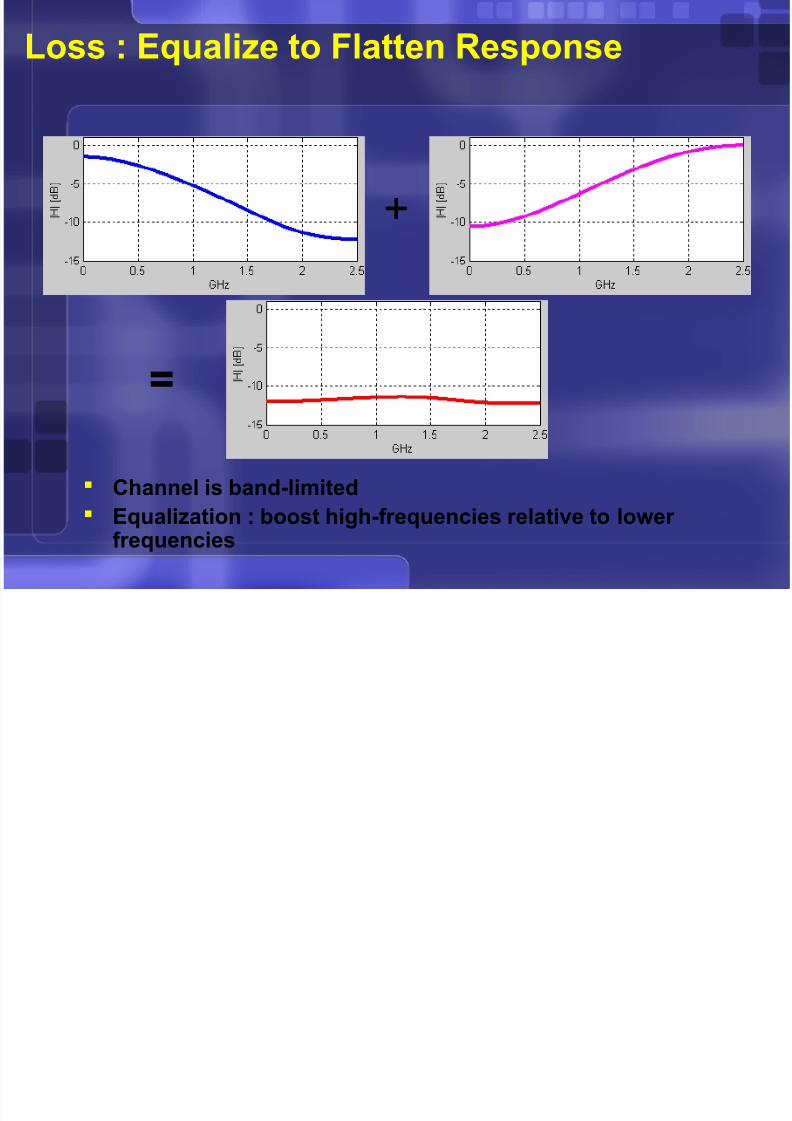
Transmit and Receive Equalization
Transmit and receive equalizers are
combined to make a range restricted DFE Tx equalizer functions as the feed-forward filter
Rx equalizer restricted in performance of loop
TAP SEL
LOGIC
TX
DATA
3
RX
DATA

8/8/2019 Electronics May03
http://slidepdf.com/reader/full/electronics-may03 33/49
Tx & Rx Equalization Ranges
TX Driver/Equalizer : 5 taps
1(pre)+1(main)+3(post)
RX Equalizer
5-17 taps after main
Pick any 5 taps

8/8/2019 Electronics May03
http://slidepdf.com/reader/full/electronics-may03 34/49
Pulse Amplitude Modulation
Binary (NRZ) is 2-PAM
2-PAM uses 2-levels to send
one bit per symbol
Signaling rate = 2 x Nyquist
4-PAM uses 4-levels to send2 bits per symbol
Each level has 2 bit value
Signaling rate = 4 x Nyquist
00
01
11
10
1
0
1
0

8/8/2019 Electronics May03
http://slidepdf.com/reader/full/electronics-may03 35/49
When Does 4-PAM Make Sense?
First order : slope of S21
3 eyes : 1 eye = 10db
loss > 10db/octave : 4-PAMshould be considered
0.0
-20db
-40db
-60db

8/8/2019 Electronics May03
http://slidepdf.com/reader/full/electronics-may03 36/49
Example : 5Gbps Over 26” FR4
With No Equalization

8/8/2019 Electronics May03
http://slidepdf.com/reader/full/electronics-may03 37/49
Example : 5Gbps Over 26” FR4
Correct Tx Equalization

8/8/2019 Electronics May03
http://slidepdf.com/reader/full/electronics-may03 38/49
Example : 5Gbps Over 26” FR4
Under Equalized
8/8/2019 Electronics May03
http://slidepdf.com/reader/full/electronics-may03 39/49
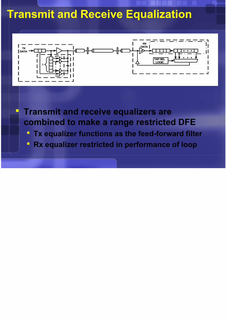
Example : 5Gbps Over 26” FR4
Over Equalized
8/8/2019 Electronics May03
http://slidepdf.com/reader/full/electronics-may03 40/49
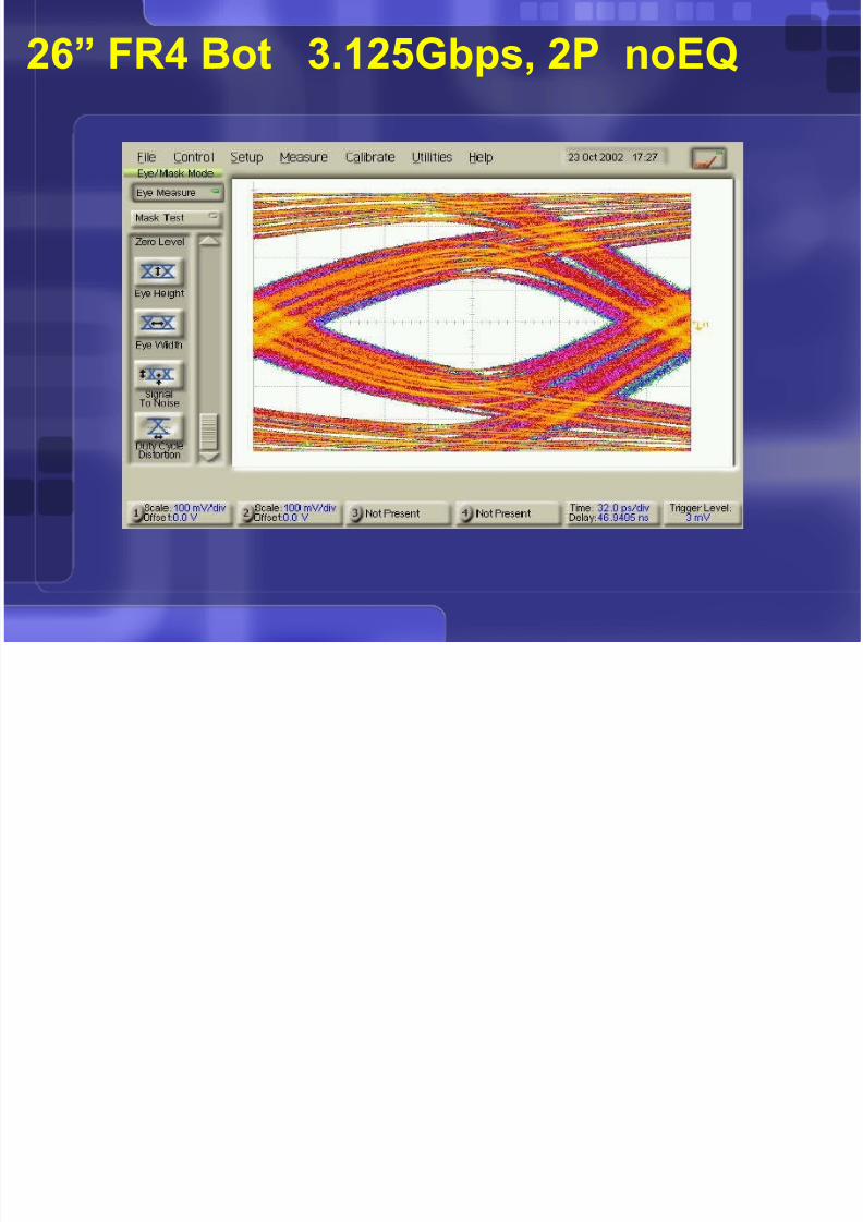
26” FR4 Bot 3.125Gbps, 2P noEQ

8/8/2019 Electronics May03
http://slidepdf.com/reader/full/electronics-may03 41/49
26” FR4 Bot 3.125Gbps, 2P w/EQ

8/8/2019 Electronics May03
http://slidepdf.com/reader/full/electronics-may03 42/49
26” FR4 Bot 6.4Gbps, 2P w/3G EQ

8/8/2019 Electronics May03
http://slidepdf.com/reader/full/electronics-may03 43/49
26” FR4 Bot 6.4Gbps, 2P w/EQ

8/8/2019 Electronics May03
http://slidepdf.com/reader/full/electronics-may03 44/49
26” FR4 Top 6.4Gbps, 2P w/EQ

8/8/2019 Electronics May03
http://slidepdf.com/reader/full/electronics-may03 45/49

8/8/2019 Electronics May03
http://slidepdf.com/reader/full/electronics-may03 46/49
26” Nelco6k-cb Top 10Gbps, 4P

8/8/2019 Electronics May03
http://slidepdf.com/reader/full/electronics-may03 47/49
26” Nelco6k-cb Top 6.4Gbps, 2P
8/8/2019 Electronics May03
http://slidepdf.com/reader/full/electronics-may03 48/49
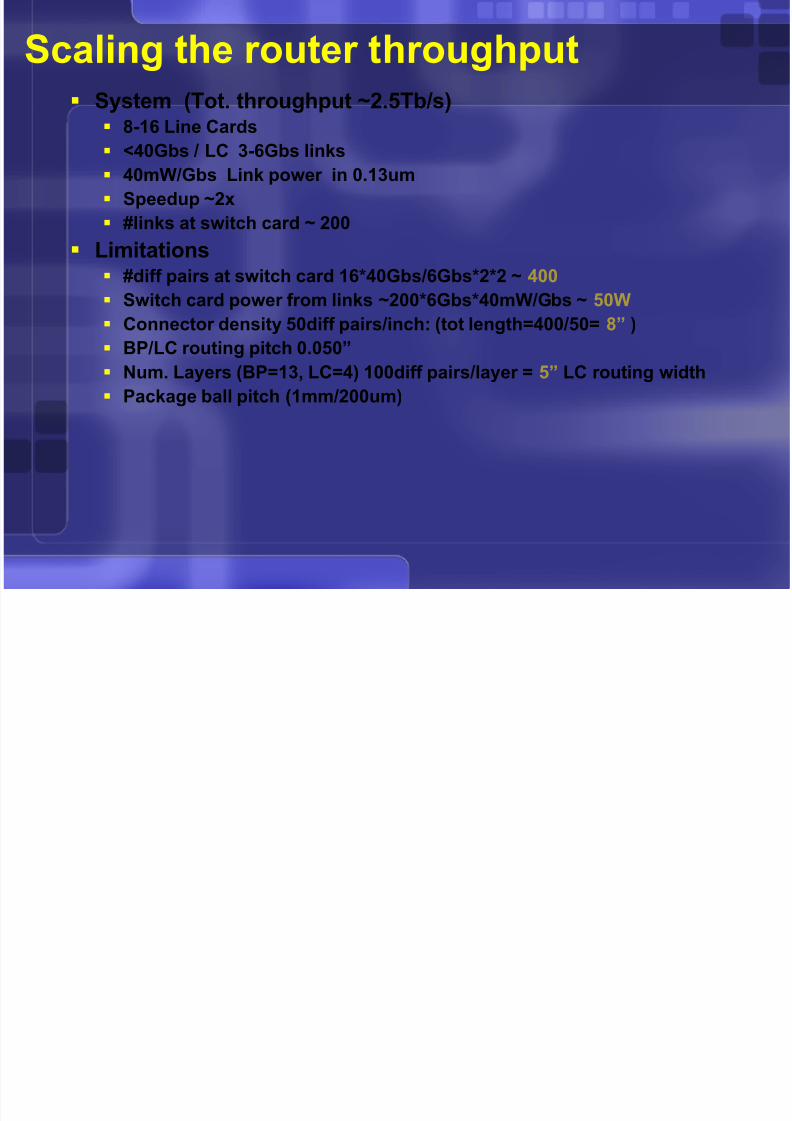
Scaling the router throughput System (Tot. throughput ~2.5Tb/s)
8-16 Line Cards
<40Gbs / LC 3-6Gbs links
40mW/Gbs Link power in 0.13um
Speedup ~2x
#links at switch card ~ 200
Limitations
#diff pairs at switch card 16*40Gbs/6Gbs*2*2 ~ 400 Switch card power from links ~200*6Gbs*40mW/Gbs ~ 50W
Connector density 50diff pairs/inch: (tot length=400/50= 8” )
BP/LC routing pitch 0.050”
Num. Layers (BP=13, LC=4) 100diff pairs/layer = 5” LC routing width
Package ball pitch (1mm/200um)
S

8/8/2019 Electronics May03
http://slidepdf.com/reader/full/electronics-may03 49/49
Scaling the router throughput System (Tot. throughput ~100Tb/s)
100 Line Cards
1Tbs / LC 10Gbs links 4mW/Gbs Link power in 0.065um
Speedup ~1x
#links at switch card ~ 10k
Limitations #diff pairs at switch card 20k
Switch card power from links in 0.13um~10k*10Gbs*4mW/Gbs ~ 400W
Connector density 50diff pairs/inch: (tot length=20k/50= 400” )
BP/LC routing pitch 0.050”
Num. Layers (BP=13, LC=4) 5k diff pairs/layer = 250” LC routing width
Package ball pitch (1mm/200um)