Embed Size (px)
Citation preview
Page 1NCP1 Series
Electropneumatic Transducer (I/P)Installation, Operation and Maintenance Instructions
AutomationDirect3505 Hutchinson RoadCumming, GA 300401-800-633-0405
Nitra NCP1 Series
Contents
Section Description Page
1.0 Description & Installation 2
2.0 Operation 3
3.0 Approvals 5
4.0 Maintenance 5
5.0 Troubleshooting 6
6.0 Warranty 6
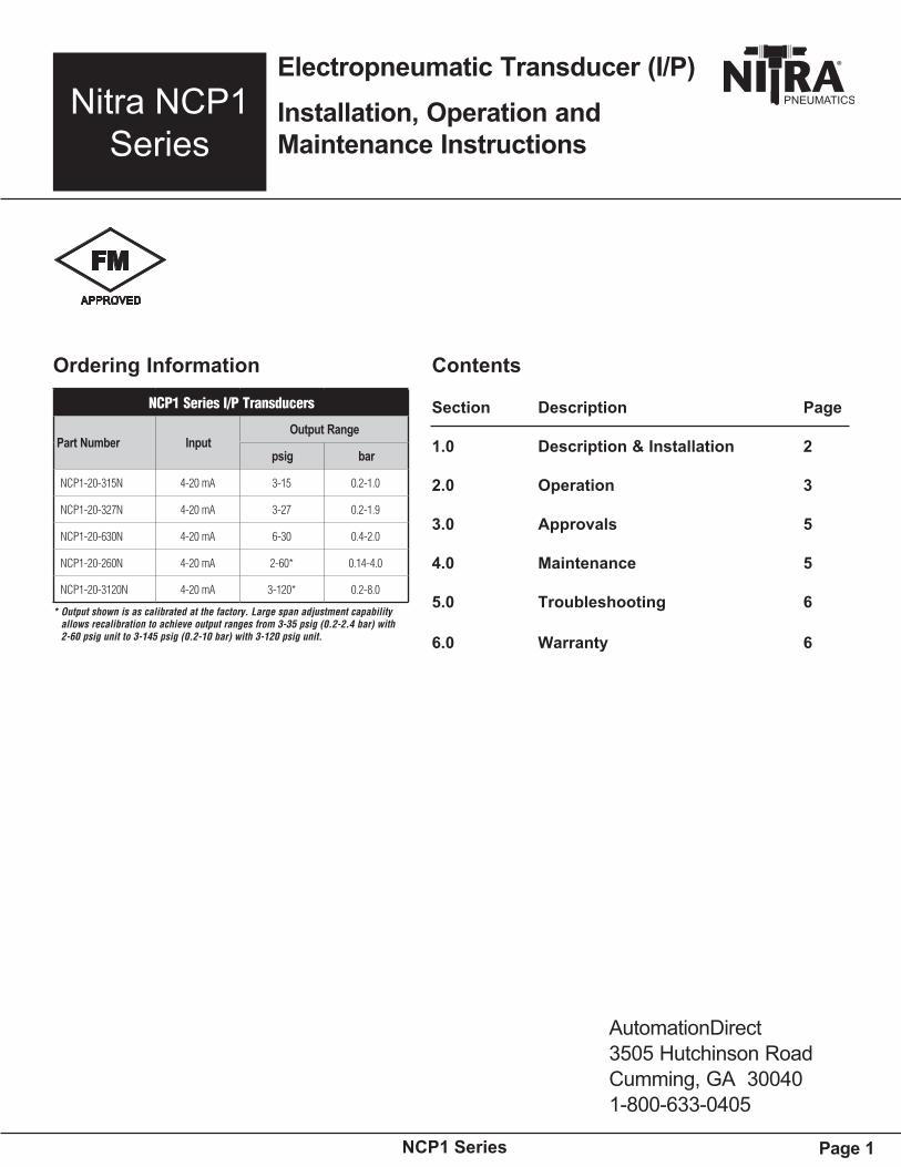
NCP1 Series I/P Transducers
Part Number InputOutput Range
psig bar
NCP1-20-315N 4-20 mA 3-15 0.2-1.0
NCP1-20-327N 4-20 mA 3-27 0.2-1.9
NCP1-20-630N 4-20 mA 6-30 0.4-2.0
NCP1-20-260N 4-20 mA 2-60* 0.14-4.0
NCP1-20-3120N 4-20 mA 3-120* 0.2-8.0
* Output shown is as calibrated at the factory. Large span adjustment capability allows recalibration to achieve output ranges from 3-35 psig (0.2-2.4 bar) with 2-60 psig unit to 3-145 psig (0.2-10 bar) with 3-120 psig unit.
Ordering Information
Page 2NCP1 Series
DANGER, WARNING, CAUTION and NOTE statements
DANGER Refers to conditions or hazards which could result in serious personal injury or death.
WARNING Refers to conditions or hazards which could result in personal injury.
CAUTION Refers to conditions or hazards which could result in equipment or property damage.
NOTE Alerts you to facts or special instructions.
ALL DANGER, WARNING, AND CAUTION NOTICES MUST BE COMPLIED WITH IN FULL
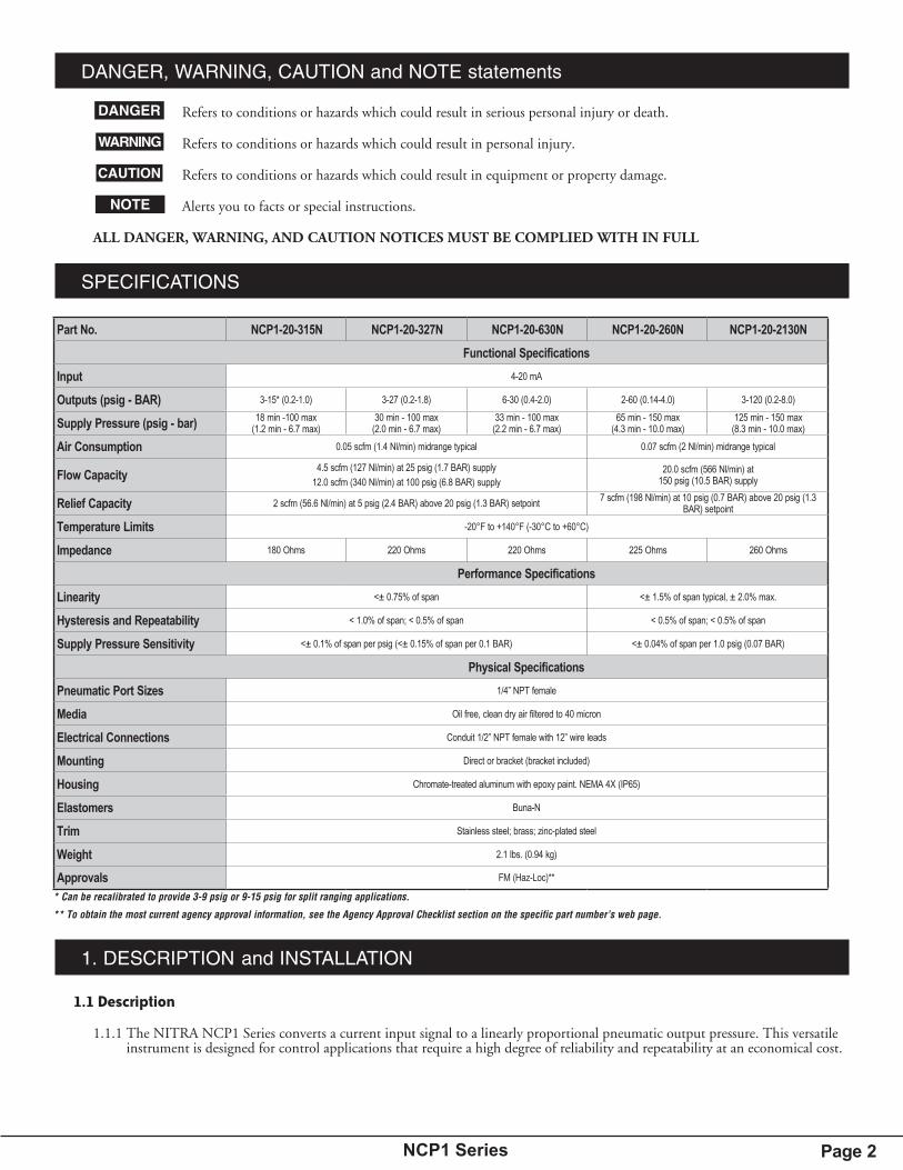
SPECIFICATIONS
* Can be recalibrated to provide 3-9 psig or 9-15 psig for split ranging applications.
** To obtain the most current agency approval information, see the Agency Approval Checklist section on the specific part number’s web page.
Part No. NCP1-20-315N NCP1-20-327N NCP1-20-630N NCP1-20-260N NCP1-20-2130NFunctional Specifications
Input 4-20 mA
Outputs (psig - BAR) 3-15* (0.2-1.0) 3-27 (0.2-1.8) 6-30 (0.4-2.0) 2-60 (0.14-4.0) 3-120 (0.2-8.0)
Supply Pressure (psig - bar) 18 min -100 max (1.2 min - 6.7 max)
30 min - 100 max (2.0 min - 6.7 max)
33 min - 100 max (2.2 min - 6.7 max)
65 min - 150 max (4.3 min - 10.0 max)
125 min - 150 max (8.3 min - 10.0 max)
Air Consumption 0.05 scfm (1.4 Nl/min) midrange typical 0.07 scfm (2 Nl/min) midrange typical
Flow Capacity 4.5 scfm (127 Nl/min) at 25 psig (1.7 BAR) supply12.0 scfm (340 Nl/min) at 100 psig (6.8 BAR) supply
20.0 scfm (566 Nl/min) at 150 psig (10.5 BAR) supply
Relief Capacity 2 scfm (56.6 Nl/min) at 5 psig (2.4 BAR) above 20 psig (1.3 BAR) setpoint 7 scfm (198 Nl/min) at 10 psig (0.7 BAR) above 20 psig (1.3 BAR) setpoint
Temperature Limits -20°F to +140°F (-30°C to +60°C)
Impedance 180 Ohms 220 Ohms 220 Ohms 225 Ohms 260 Ohms
Performance SpecificationsLinearity <± 0.75% of span <± 1.5% of span typical, ± 2.0% max.
Hysteresis and Repeatability < 1.0% of span; < 0.5% of span < 0.5% of span; < 0.5% of span
Supply Pressure Sensitivity <± 0.1% of span per psig (<± 0.15% of span per 0.1 BAR) <± 0.04% of span per 1.0 psig (0.07 BAR)
Physical SpecificationsPneumatic Port Sizes 1/4” NPT female
Media Oil free, clean dry air filtered to 40 micron
Electrical Connections Conduit 1/2” NPT female with 12” wire leads
Mounting Direct or bracket (bracket included)
Housing Chromate-treated aluminum with epoxy paint. NEMA 4X (IP65)
Elastomers Buna-N
Trim Stainless steel; brass; zinc-plated steel
Weight 2.1 lbs. (0.94 kg)
Approvals FM (Haz-Loc)**
1. DESCRIPTION and INSTALLATION
1.1 Description
1.1.1 The NITRA NCP1 Series converts a current input signal to a linearly proportional pneumatic output pressure. This versatile instrument is designed for control applications that require a high degree of reliability and repeatability at an economical cost.
Page 3NCP1 Series
1.2 Principle of Operation
1.2.1 The NITRA NCP1 Series is a force balance device in which a coil is suspended in the field of a magnet by a flexure. Current flowing through the coil generates axial movement of the coil and flexure. The flexure moves towards the nozzle and creates back pressure which acts as a pilot pressure to an integral booster relay. Input signal increases cause proportional output pressure increases. Zero and Span are calibrated by turning adjust screws on the front face of the unit. Adjustment of the zero screw repositions the nozzle relative to the flexure. The span adjustment is a potentiometer that controls the amount of current through the coil.
1.3 Mounting
1.3.1 Unit may be pipe, panel, or bracket mounted. Mounting may be at any angle, though may require field adjustment. High external vibration may cause output fluctuations. Mounting in a vibration-free area is recommended.
1.4 Pneumatic Connections
1.4.1 The 1/4” NPT supply and output ports are marked “IN” and “OUT” respectively on the base of the unit. Clean all pipe lines to remove contamination before installation. If thread sealer is required, use a tape type that is compatible with the media. Liquid or paste type thread sealer is not recommended. Clean dry instrument quality air must be used. To insure optimum performance supply pressure should be regulated. To provide stable inlet pressure and prevent contamination of the internal section of the transducer the use of an Instrument Air Filter Regulator is recommended. The two unmarked ports on the base of the unit are gauge ports but may be used as alternative output ports. Any unused ports must be plugged.
WARNING The I/P transducer enclosure contains aluminum and is considered to constitute a potential risk of ignition by impact or friction and must be taken into account during installation.
1.5 Electrical Connections
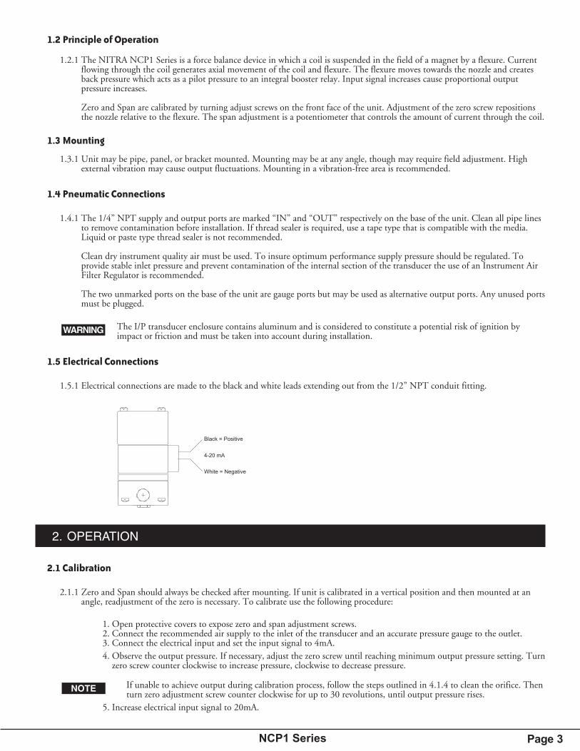
1.5.1 Electrical connections are made to the black and white leads extending out from the 1/2” NPT conduit fitting.
Black = Positive
White = Negative
4-20 mA
2. OPERATION
2.1 Calibration
2.1.1 Zero and Span should always be checked after mounting. If unit is calibrated in a vertical position and then mounted at an angle, readjustment of the zero is necessary. To calibrate use the following procedure:
1. Open protective covers to expose zero and span adjustment screws. 2. Connect the recommended air supply to the inlet of the transducer and an accurate pressure gauge to the outlet. 3. Connect the electrical input and set the input signal to 4mA. 4. Observe the output pressure. If necessary, adjust the zero screw until reaching minimum output pressure setting. Turn
zero screw counter clockwise to increase pressure, clockwise to decrease pressure.
NOTE If unable to achieve output during calibration process, follow the steps outlined in 4.1.4 to clean the orifice. Then turn zero adjustment screw counter clockwise for up to 30 revolutions, until output pressure rises.
5. Increase electrical input signal to 20mA.
Page 4NCP1 Series
6. Observe the output pressure. If necessary adjust the span screw until reaching maximum output pressure setting.
NOTE For I/P (current) input models turn span screw counter clockwise to increase pressure, clockwise to decrease pressure.
7. The Zero and Span adjustments are interactive. After adjusting the span it will be necessary to recheck the zero. Repeat steps 3-6 until both end points are at the required values.
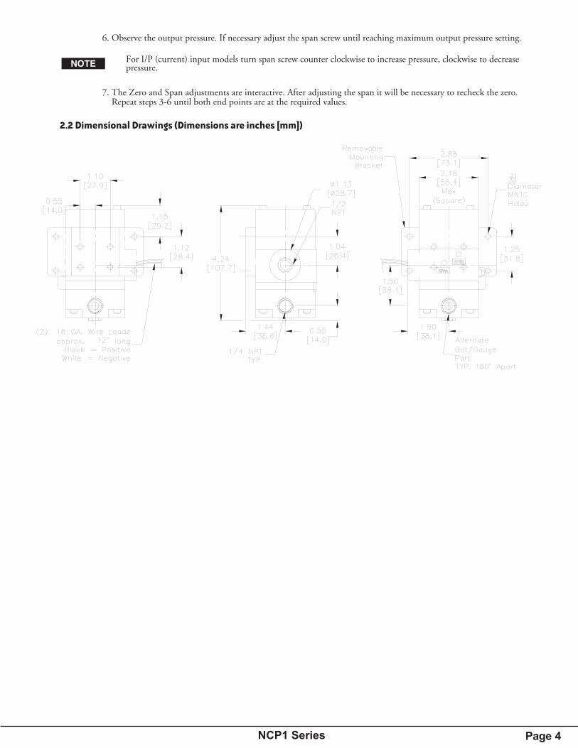
2.2 Dimensional Drawings (Dimensions are inches [mm])
Page 5NCP1 Series
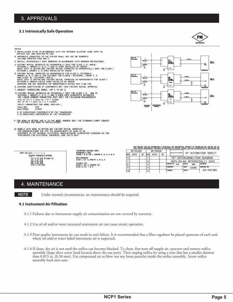
3. APPROVALS
3.1 Intrinsically Safe Operation
4. MAINTENANCE
NOTE Under normal circumstances, no maintenance should be required.
4.1 Instrument Air Filtration
4.1.1 Failures due to instrument supply air contamination are not covered by warranty.
4.1.2 Use of oil and/or water saturated instrument air can cause erratic operation.
4.1.3 Poor quality instrument air can result in unit failure. It is recommended that a filter regulator be placed upstream of each unit where oil and/or water laded instrument air is suspected.
4.1.4 If clean, dry air is not used the orifice can become blocked. To clean, first turn off supply air, unscrew and remove orifice assembly (large silver screw head located above the out port). Then unplug orifice by using a wire that has a smaller diamter than 0.015 in. (0.38 mm). Use compressed air to blow out any loose particles inside the orifice assembly. Screw orifice assembly back into unit.
Page 6NCP1 Series
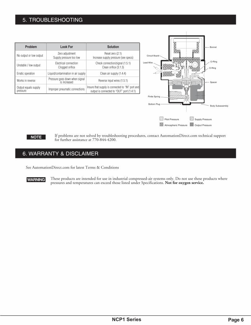
5. TROUBLESHOOTING
Pilot Pressure
Atmospheric Pressure
Supply Pressure
Output Pressure
Lead Wire
Bonnet
O-Ring
O-Ring
Body Subassembly
Circuit Board
Bottom Plug
Spacer
Pintle Spring
Problem Look For Solution
No output or low outputZero adjustment
Supply pressure too lowReset zero (2.1)
Increase supply pressure (see specs)
Unstable / low outputElectrical connection
Clogged orificeCheck connection/signal (1.5.1)
Clean orifice (3.1.3)
Erratic operation Liquid/contamination in air supply Clean air supply (1.4.4)
Works in reverse Pressure goes down when signal is increased Reverse input wires (1.5.1)
Output equals supply pressure Improper pneumatic connections
Insure that supply is connected to “IN” port andoutput is connected to “OUT” port (1.4.1)
NOTE If problems are not solved by troubleshooting procedures, contact AutomationDirect.com technical support for further assistance at 770-844-4200.
6. WARRANTY & DISCLAIMER
See AutomationDirect.com for latest Terms & Conditions
WARNING These products are intended for use in industrial compressed-air systems only. Do not use these products where pressures and temperatures can exceed those listed under Specifications. Not for oxygen service.