Embed Size (px)
Citation preview

UNIVERSIDADE DA BEIRA INTERIOR Ciências da saúde
Electrospun poly(ε-caprolactone) nanofibers for
bone regeneration and other biomedical
applications
Tiago António Martins Valente
Master Degree Thesis in
Biomedical Sciences
(2nd cycle of studies)
Supervisor: Prof. Ilídio Joaquim Sobreira Correia (PhD)
Covilhã, June 2011

UNIVERSIDADE DA BEIRA INTERIOR Ciências da saúde
Produção de nanofibras de poli(ε-caprolactona)
por electrospinning para futura aplicação na
regeneração óssea e outras aplicações biomédicas
Tiago António Martins Valente
Dissertação para a obtenção do Grau de Mestre em
Ciências Biomédicas
(2º Ciclo de estudos)
Orientador: Prof. Doutor Ilídio Joaquim Sobreira Correia
Covilhã, Junho de 2011

iii

iv
“Imagination is more important than knowledge. For while knowledge
defines all we currently know and understand, imagination points to all we
might yet discover and create.”
Albert Einstein

v
Acknowledgements
I would like to express my deepest gratitude to my supervisor, Professor Ilídio
Correia, for all the support, teaching, guidance and broad multidisciplinary knowledge that
shared with me during this journey. Moreover, I would like to thank him for doing the outmost
to ensure all the necessary conditions for the development of this study.
I would also to thank to Professor António Morão for providing the microfiltration
membranes necessary for one of the tasks of this project.
In addition, I would like to thank José Nunes, for all the help and for having done the
filtration tests on the modified membranes.
Moreover, I would like to thank Eng. Ana Paula from the Optics department of
Universidade da Beira Interior for the help in acquiring the lots of scanning electron
microscopy images.
I would like to thank all of my group colleagues for all the advices, teaching and
support during the good and the bad days. Principally, their friendship and joy was truly
important to face all the difficulties during the development of this project.
I also thank to all of my friends for all the good times shared, advices and patience
during not only the academic life, but also during my entire life.
Finally, I thank to my parents and my brother for granted me the possibility to make
this master degree thesis. For all their education, support, advices, patience and love I do
thank them a lot. Their presence in my life has been truly important in every decision I take.

vi

vii
Abstract
Bone tissue is a complex and hierarchical structure with many functions in the body. Although
this tissue has the capability for self-generation, large bone defects due to various diseases or
fractures may need clinical treatment. However, the current clinical treatments are based on
bone grafts and other bone substitutes, which have several limitations. Tissue engineering is a
multidisciplinary field that emerged from the need to extinguish these clinical limitations.
This vast field of science uses various tools in seeking for effective tissue regeneration. In this
context, this work aimed the production of functional materials that mimic the nanostructure
of bone tissue and therefore the cellular microenvironment, promoting bone regeneration. In
this way, an electrospinning apparatus was mounted and optimized for the production of
polycaprolactone nanofibers. Additionally, several electrospinning parameters that influence
the morphology of the electrospun nanofibers produced were studied. For application in bone
regeneration, the combination of polycaprolactone nanofibers with β-tricalcium phosphate
scaffolds, mechanically more resistant, was investigated. Moreover, a preliminary study about
the capacity for this system to allow controlled release of biomolecules was conducted
through the incorporation of a model protein into the nanofibers. In order to characterize the
biological properties of the systems produced, in vitro cytotoxicity assays were performed.
These assays revealed that the polycaprolactone nanofibers produced are biocompatible and
that the coating of β-tricalcium phosphate scaffolds with these nanofibers improve this
biological performance, when compared to ceramic scaffolds without coating. The
potentiality of nanofibers herein produced was also evaluated for the modification of
microfiltration membranes. These membranes showed a large increase in the plasmid DNA
rejection.
Keywords
Electrospinning, polycaprolactone, nanofibers, tissue engineering, coating of scaffolds,
modification of membranes.

viii

ix
Resumo
O tecido ósseo é uma estrutura complexa com diversas funções no organismo. Apesar deste
tecido possuir uma capacidade de auto-regeneração única, defeitos ósseos com uma grande
extensão causados por doenças ou fracturas podem necessitar de tratamento em meio
hospitalar. No entanto, estes tratamentos são algo limitados, pois baseiam-se em transplantes
e em substitutos ósseos compostos por materiais inertes. A engenharia de tecidos é uma área
multidisciplinar que emergiu da necessidade de extinguir estas adversidades. Este vasto
campo científico utiliza diversas ferramentas na procura de uma regeneração de tecidos mais
eficaz. Neste âmbito, este trabalho pretende produzir materiais funcionais que mimetizem a
nanoestrutura do tecido ósseo e, portanto, o microambiente celular, favorecendo a
regeneração óssea. Com base neste pressuposto, montou-se um sistema de electrospinning e
procedeu-se à sua optimização para a produção de nanofibras de policaprolactona.
Adicionalmente, diversos parâmetros que influenciam a morfologia das nanofibras produzidas
por electrospinning foram estudados. Para aplicação na regeneração óssea, a combinação das
nanofibras de policaprolactona com scaffolds de β-tricálcio fosfato, mais resistentes
mecanicamente, foi investigada. Adicionalmente, foi realizado um estudo preliminar sobre a
capacidade deste sistema permitir a libertação controlada de biomoléculas, através da
incorporação de uma proteína modelo nas nanofibras. O perfil citotóxico dos sistemas
produzidos foi caracterizado através de ensaios in vitro. Estes estudos revelaram que as
nanofibras de policaprolactona produzidas são biocompativeis e que o revestimento dos
scaffolds de β-tricálcio fosfato com estas nanofibras melhora as propriedades biológicas em
relação aos scaffolds cerâmicos sem revestimento. A potencialidade das nanofibras
produzidas foi ainda testada na modificação de membranas de microfiltração. Este estudo
demonstrou um aumento na rejeição de DNA plasmídico após o revestimento da membrana
com as nanofibras.
Palavras-chave
Electrospinning, policaprolactona, nanofibras, engenharia de tecidos, revestimento de
scaffolds, modificação de membranas.

x

xi
Table of Contents
Acknowledgments .............................................................................................. v
Abstract....................................................................................................... vii
Resumo ......................................................................................................... ix
List of Figures ................................................................................................ xiv
List of Tables ................................................................................................ xvii
List of Acronyms ............................................................................................. xix
Chapter I - Introduction
1 Introduction ................................................................................................ 2
1.1 Bone tissue ................................................................................................. 2
1.1.1 Formation and composition of bone .......................................................... 2
1.1.2 Structure of bone ................................................................................. 3
1.1.3 Bone self-regenerative ability ................................................................. 5
1.1.4 Clinical treatment used for bone regeneration: motives and purposes ................ 7
1.2 Tissue engineering ........................................................................................ 8
1.2.1 Biomaterials for bone tissue engineering .................................................... 8
1.2.2 Nanotechnological approaches for bone tissue engineering ............................ 10
1.2.3 Electrospinning ................................................................................. 13
1.2.4 Incorporation of growth factors into nanofibers .......................................... 19
1.3 The application of nanofibers for biotechnological purposes ................................... 20
1.4 Objectives ................................................................................................ 22
Chapter II – Materials and Methods
2 Materials and Methods ................................................................................. 24
2.1 Materials .................................................................................................. 24
2.2 Methods ................................................................................................... 24
2.2.1 Electrospinning setup ......................................................................... 24
2.2.2 Preparation of PCL polymer solutions ..................................................... 24
2.2.3 Optimization of the electrospinning process .............................................. 25

xii
2.2.4 Scanning electron microscopy ................................................................ 25
2.2.5 Coating of the 3D β-Tricalcium phosphate scaffolds with PCL nanofibers ........... 25
2.2.6 Coating the TCP scaffolds with BSA incorporated into PCL nanofibers ............... 26
2.2.7 Proliferation of human osteoblast cells in the presence of the different scaffolds.26
2.2.8 Characterization of the cytotoxicity profile of the different scaffolds ............... 27
2.2.9 Coating of the filtration membranes (FSM 0.45PP) with PCL nanofibers ............. 27
Chapter III – Results and Discussion
3 Results and Discussion .................................................................................. 29
3.1 Electrospinning setup .................................................................................. 29
3.2 Optimization and characterization of the electrospun PCL nanofibers produced ........... 31
3.2.1 Effect of polymer concentration on the nanofiber properties ......................... 32
3.2.2 Effect of the applied voltage on the nanofiber properties ............................. 34
3.2.3 Effect of the polymer flow rate on the nanofiber properties .......................... 36
3.2.4 Effect of the distance between the needle tip and collector on the nanofibers
properties ............................................................................................... 38
3.2.5 Effect of the needle diameter on the nanofibers properties ........................... 39
3.3 Coating of the TCP scaffolds with PCL nanofibers ................................................ 41
3.4 Evaluation of the cytotoxic profile of the different materials .................................. 42
3.5 Modification of microfiltration membranes (FSM 0.45PP) with PCL nanofibers .............. 45
Chapter IV – Conclusions and Future Perspectives
4 Conclusions and future perspectives ................................................................ 48
Bibliography ............................................................................................ 50

xiii

xiv
List of Figures
Figure 1 – Bone developmental processes ................................................................ 2
Figure 2 – Structure of bone ................................................................................. 4
Figure 3 – Illustration of macro to nano structures of the bone ...................................... 4
Figure 4 – Schematic representation of fracture healing .............................................. 5
Figure 5 – Influence of architecture scale on cell binding and spreading ......................... 11
Figure 6 – Geometric phases of the polymer fluid in electrospinning process: Taylor cone,
continuous jet and instability region ..................................................................... 14
Figure 7 – Schematic setup for various nozzle types .................................................. 18
Figure 8 – Schematic illustration of various electrospinning setups for control of the fibers
alignment...................................................................................................... 19
Figure 9 – Images of the electrospinning apparatus .................................................. 30
Figure 10 – Images of the typical polymeric deposition area on the collector (a); the wood
pallet used to assure user’s safety (b) ................................................................... 30
Figure 11 – SEM images of the samples obtained during the electrospinning optimization
process ......................................................................................................... 31
Figure 12 – Effect of the variation of polymer concentration on fibers formation .............. 33
Figure 13 – Morphology of the nanofibers produced with the different applied voltage when
the other parameters were held constant .............................................................. 35
Figure 14 – Effect of the flow rate on the morphology of the nanofibers ........................ 37
Figure 15 - Effect of the distance between the needle tip and collector on the morphology of
the nanofibers, when all the other parameters are held constant ................................. 39
Figure 16 – Effect of the needle diameter on morphology of the nanofibers, maintaining the
other parameters constant ................................................................................. 40
Figure 17 – SEM images of the coated TCP scaffolds.................................................. 41

xv
Figure 18 – Optical microscopic photographs of human osteoblast cells after 24, 48 and 72 h
of being seeded .............................................................................................. 43
Figure 19 – Cellular activities measured by the MTS assay after 24, 48 and 72 h of being
seeded ......................................................................................................... 44
Figure 20 – Commercial microfiltration membranes coated with PCL nanofibers ............... 46
Figure 21 – Retention of pDNA for modified membranes (FSM 0.45PP) in function of the
deposition time of the electrospun PCL nanofibers ................................................... 46

xvi

xvii
List of Tables
Table 1 – Comparison of different methods for the production of polymer nanofiber
scaffolds.. ..................................................................................................... 12
Table 2 – Dielectric constants of the most used solvents applied in the preparation of
electrospinning solutions ................................................................................... 15

xviii

xix
List of Acronyms
ALP Alkaline phosphatase
BMPs Bone morphogenetic proteins
BSA Bovine serum albumin
DMEM-F12 Dulbecco’s modified eagle’s medium
EDTA Ethylenediaminetetraacetic acid
EGF Epidermal growth factor
FBS Fetal bovine serum
FDA Food and Drugs Administration
HA Hydroxyapatite
RO Reverse osmosis
MF Microfiltration
MSCs Mesenchymal stem cells
MTS 3-(4,5-dimethylthiazol-2-yl)-5-(3-carboxymethoxyphenyl)-2-(4-sulfophenyl)-
2H-tetrazolium reagent, inner salt
NF Nanofiltration
PCL Poly(ε-caprolactone)
pDNA Plasmid DNA
SEM Scanning electron microscopy
TCP β-Tricalcium phosphate TGF- β Transforming growth factor - β
UF Ultrafiltration
VEGF Vascular endothelial growth factor
3D Three-dimensional

xx

Chapter I
Introduction

Chapter I - Introduction
2
1. Introduction
1.1 Bone tissue
1.1.1 Formation and composition of bone
As part of the skeletal, bone plays several critical functions in the body: it is involved
in structural support, is fundamental for locomotion, ensures protection for the internal
organs (chest, cranium, spine), provides tissue base for the production of blood cells
(haematopoiesis) and immune cells and form a mineral reservoir to maintain electrolyte
homeostasis in the body [1, 2].
Bones are formed through two distinct pathways (figure 1): endochondral ossification
gives rise to long bones, which include appendicular skeleton, facial bones, vertebrae and
lateral clavicles; intramembranous ossification gives rise to the flat bones, comprising the
cranium and medial clavicles [3]. Both types of ossification involve an initial condensation of
mesenchyme, where cells are positioned adjacent one to another, and the successive
formation of calcified bone [4]. However, intramembranous ossification accomplishes this
directly, whereas endochondral ossification has an intermediate step in which an avascular
tissue (cartilage) is formed before being mineralized and converted into bone tissue [3, 5].
Figure 1 - Bone developmental processes (Adapted from [3]).
Bone tissue is composed by mineral components (70%) and organic components (30%).
The first one is almost all composed of an analogous form of hydroxyapatite [Ca10(PO4)6(OH2)],
that can incorporate ions like magnesium, zinc, sodium, potassium, chlorine, fluorine and

Chapter I - Introduction
3
strontium [6]. The high surface/volume ratio and the crystals irregularity make them more
soluble and easily mobilized to metabolic demands [6].
The organic part of the bone is composed by 2% of bone cells and 98% of organic components
from the extracellular matrix (ECM) [6]. The principal organic component of ECM is collagen
type I. This protein is a heteropolymer of three chains, each of them having the primary
structure (Gly-X-Y)n, where X and Y are frequently proline or hydroxyproline [7]. Collagen is
deposited in matrix along the mechanical stress lines and provides a backbone for the
deposition of bone mineral [3, 6]. The mechanical properties of a bone are determined by
this combination of materials. The inorganic phase is related to the resistance during
compression, whereas the organic phase is responsible mainly for the viscoelastic properties
in tension or shear [8].
The cellular elements in bone act as metabolic regulators and are responsible for the
continuous remodelling of bone tissue [6]. Three types of cells coexist in bone: Osteoblasts
are derived from marrow stromal fibroblastic stem cells. These cells are involved in the
synthesis of a decalcified organic matrix, mainly constituted by collagen type 1, called
osteoid. In this process, they produce large amounts of alkaline phosphatase, an enzyme that
prepares the matrix for mineralization [9]; Osteocytes (derived from osteoblasts) are
surrounded during the mineralization process in bone lacunae that have a network of
canaculi, through which they make their metabolic exchanges and regulate the blood-calcium
homeostasis [3, 6]; Osteoclasts (derived from the monocyte-macrophage lineage) are giant
cells that produce enzymes, like acidic phosphatise, and are responsible for bone resorption
[10].
Bone tissue is maintained by a balance of bone-forming and bone-resorbing cells. A
malfunction in this equilibrium results in an excessive bone resorption that leads to
anomalous conditions including osteoporosis, osteoarthritis, periodontitis and metastatic bone
disease [11, 12].
1.1.2 Structure of bone
Morphologically bone can be described based on its density: cortical (compact) bone
and cancellous (spongy or trabecular) bone [3, 11].
Cortical bone has as fundamental unit the osteon or Haversian system. Osteons consist
of a central canal (Haversian canal) derived from intraosseous arteries and perforating canals
surrounded by concentric rings of the matrix [11]. Due to the preferential orientation of
osteons along the direction of the forces supported by the diaphysis, that arteriole is almost
always disposed to length of bone. The Haversian canal communicates to each other by
horizontal branches called Volkmann canals [6].
Cancellous bone presents a structure of intersecting trabeculae, following mechanical
force lines, giving them a greater resistance to compressive forces. On the other hand,

Chapter I - Introduction
4
cortical bone is better able to withstand forces of extension-flexion and torsion forces [6].
The network of trabeculae is covered by an epithelial membrane of osteoblasts that can be
activated to form more bone lamellae. On the trabecular surface the osteoclasts are involved
in resorbing bone matrix and releasing minerals in Howship lacunae [6].
A schematic representation of both bone types can be observed in figure 2.
Figure 2 - Structure of bone: a) Cancellous bone. b) Cortical bone (Adapted from [3]).
The difference between cancellous and cortical bone is not only structural but also
functional: cortical bone provides mechanical and protective functions, while cancellous bone
is involved in metabolic functions, like the calcium homeostasis [3].
The hierarchical arrangement of bone tissue is represented in figure 3.
Figure 3 – Illustration of the macro to nano structures of the bone (Adapted from [13]).

Chapter I - Introduction
5
1.1.3 Bone self-regenerative ability
Bone is highly vascularized and a very dynamic tissue, since it has both high
mechanical properties and regenerative capacity [14]. This regenerative property is crucial
for skeletal homeostasis and fracture repair. Unlike soft tissue healing, the regeneration of
the natural bone tissue occurs without scar formation [15]. Fracture healing can be divided
into three phases that form a continuous healing process after injury. In temporal order, this
process comprises an inflammatory phase, a reparative phase and a remodeling phase [15,
16]. The overall process of bone repair is illustrated in figure 4.
Figure 4 - Schematic representation of fracture healing (Adapted from [15]).
Inflammatory phase
At the onset of bone damage, an inflammatory response is elicited during 1 week post
fracture. This reaction helps to immobilize the fracture in two ways: pain causes the
individual to protect the injury and the enlargement of the site (swelling) keeps the fracture
from moving. The blood vessels rupture results in the activation of the complement cascade,
platelet aggregation, and release of its granule contents, which triggers chemotactic signals
[15, 16]. Hemostasis is guaranteed by platelets and by the formation of a hematoma. On the
other hand, the hematoma become a fibrin network that provides pathways for cellular
migration and serves as a source of signal molecules, that initiate cellular events essential to

Chapter I - Introduction
6
fracture healing. Lymphocytes, blood monocytes, macrophages and osteoclasts are attracted
to the injury site and are activated to ―clean up‖ the wound of biological debris and to
release cytokines that can stimulate angiogenesis [15, 16]. Growth factors that are released
include insulin-like growth factor, vascular endothelial growth factor (VEGF), platelet-derived
growth factor, transforming growth factor-β (TGF-β) and epidermal growth factor. These
growth factors play important roles in the proliferation and differentiation of the
mesenchymal stem cells (MSCs) [16].
Reparative phase
The reparative phase occurs before the inflammatory phase subsides and lasts for
several weeks. A reparative callus tissue is formed at fracture site, which will be eventually
replaced by bone. This callus enhances mechanical stability of the site by supporting it
laterally. At this phase, the callus comprises of fibrous connective tissue, blood vessels,
cartilage, woven bone and osteoid. While fracture wastes are being resorbed, pluripotent
MSCs begin to differentiate in fibroblasts, chondroblasts and osteoblasts. As bone healing
proceeds, the pH gradually becomes neutral and then slightly alkaline, which is optimal for
alkaline phosphatase (ALP) activity and its role in the mineralization of the callus. The
reparative phase includes endochondral bone formation and intramembranous bone formation
[15, 16]. As the mineralization process evolves, the callus calcifies becoming more rigid and
the fracture site is considered internally immobilized. During this stage, collagen fibers are
not perfectly aligned and the callus is composed of an unorganized woven bone, which
connects the two fracture ends. Proteins that regulate this phase include bone morphogenetic
proteins (BMPs), parathyroid hormone-related peptide, osteopontin, osteocalcin, ALP and
bone sialoprotein [16].
Remodeling phase
The remodeling phase is the final phase in fracture healing. In this phase the
unorganized bone woven is replaced with a more organized structure and the excess of callus
is resorbed. Remodeling of fracture repair consists of osteoclastic resorption of poorly located
trabeculae and formation of new bone along lines of stress. This results in a gradual
modification of the fracture region under the influence of mechanical loads, until an optimal
stability is achieved and the bone tissue acquires similar architecture to that it had before
the fracture occurred [15, 16]. The remodeling process is guided by expression of specific
genes, protein synthesis and secretion. Osteoblast-osteoclast homeostasis is balanced by
factors like macrophage colony-stimulating factor, tumor necrosis factor-α, receptor activator
of nuclear factor κB and osteoprotegerin [16]. The events of this stage continue throughout

Chapter I - Introduction
7
adult life. Changes in estrogen levels, such as those occurring in postmenopausal women, can
alter bone homeostasis; hence the bone loses its natural stability, what explains the
increased susceptibility of women in comparison with men to bone fractures with aging [16].
1.1.4 Clinical treatment of bone: motives and purposes
In general, fracture healing is completed after 6-8 weeks after the initial injury
occurs [15]. However, the healing capacity of bone has its limitations. Large bone defects due
to trauma, fractures, cancer, periodontitis, osteoporosis and infectious diseases may not heal
by themselves and result in non-union [17-19]. The size of bone fractures and defects that
can be self-regenerated is designated as the ―critical size defect‖ and will not heal during the
lifetime of the patient. Thus, for large defects, medical intervention is often required in
order to allow bone regeneration [14, 20, 21].
The intervention mentioned above, requires the introduction of implantable materials
as bone grafts to promote the healing process [22]. Autografts (bone transplanted from the
self-patient) are considered the gold standard for bone repair due to their osteoconductivity,
osteoinductivity and biocompatibility without the risk of pathogen transfer [17]. Although
autografts exhibit the best clinical outcome, they suffer from several disadvantages such the
limited quantity, size and shape of donor tissue, and the requirement of surgery at multiple
sites to harvest donor tissue from the patient [46-49]. Allografts (bone transplanted from one
individual to another of the same species) are osteoconductive and more abundant in supply
than autografts, but carry out the risk of pathogen transmission and immune response, which
can lead to graft rejection [17, 23, 24]. Xenografts (bone transplanted from animals of
different species) hold risks of immune response and pathogen transfer between species, thus
limiting their use [1, 21]. As a result, there is a constant need for bone substitutes due to
severe bone injuries, degenerative diseases and reconstructive surgery. In recent times, there
was a remarkable increase in the use of biomaterials for bone related surgical applications
[25]. However, a gap remains to be filled since no synthetic material used until now, presents
the native properties of bone, attending both biological aspects as well as mechanical
requirements [25].
Chapter I - Introduction
8
1.2 Tissue engineering
In the last decade of the past century, tissue engineering emerges as a perspective to
abolish the limitations of tissue grafts [26]. Tissue engineering is defined as an
interdisciplinary field of research that applies methods of materials engineering and life
sciences to create artificial constructs that restore, maintain or enhance tissues and organs
functions [27, 28]. This field include a wide range of strategies employing cells, scaffolds,
cytokines and genetic manipulation for the regeneration of tissue in vivo or the production of
tissue in vitro [29]. Scaffolds are exogenous extracellular matrices designed to allow cell
adhesion and proliferation and also to provide mechanical support until the newly formed
tissue is structurally stabilized [30]. One approach to design exogenous extracellular matrices
for tissue engineering is to mimic the functions of the extracellular matrix (ECM) components
naturally found in tissues [30]. All artificial extracellular matrices used to engineer tissues
have three fundamental roles: first, they facilitate the localization and delivery of cells to
specific sites in the body; second, they define and maintain a structure for the formation of
new tissues; and finally they guide the development of new tissues with their appropriate
functions [30].
In bone tissue regeneration scaffolds are usually biodegradable and act as a
temporary matrix for cellular proliferation and for extracellular matrix deposition. In
addition, scaffolds work as a model for vascularization of new tissue (angiogenesis) and can
also serve as carriers for biologically active agents, like growth factors that can enhance the
regenerating potential of the system [31, 32].
An important aspect of tissue engineering science is the investigation of the
interactions of cells with absorbable matrices and bioactive molecules (growth factors and
cytokines), involved in the formation of new tissue [29]. The cells behaviour is strongly
determined by a complex interaction of physical and chemical signals at the nanoscale [33].
Therefore, the incorporation of biological factors in scaffolds is common practice for tissue
engineering applications. The purpose is to create a bioinspired extracellular environment
that directs specific cell responses through activation of signalling cascades. These cascades
will modulate gene expression and control important cell processes to allow tissue
regeneration [33].
1.2.1 Biomaterials for bone tissue engineering
A biomaterial has been defined in the literature as ―a substance that has been
engineered to adopt a structure which, alone or as part of a complex system, is used to direct
the course of any therapeutic or diagnostic procedure, in human or veterinary medicine’’
[34]. The biomaterials are used in tissue engineering for the manufacture of scaffolds that
Chapter I - Introduction
9
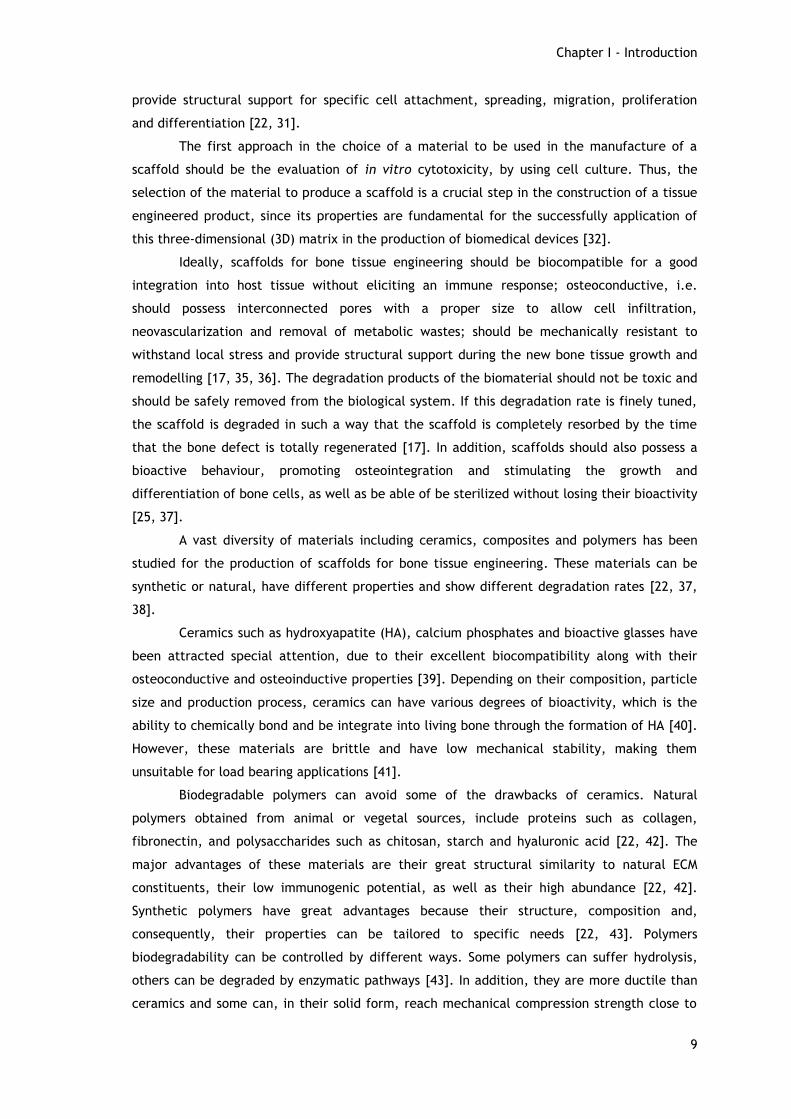
provide structural support for specific cell attachment, spreading, migration, proliferation
and differentiation [22, 31].
The first approach in the choice of a material to be used in the manufacture of a
scaffold should be the evaluation of in vitro cytotoxicity, by using cell culture. Thus, the
selection of the material to produce a scaffold is a crucial step in the construction of a tissue
engineered product, since its properties are fundamental for the successfully application of
this three-dimensional (3D) matrix in the production of biomedical devices [32].
Ideally, scaffolds for bone tissue engineering should be biocompatible for a good
integration into host tissue without eliciting an immune response; osteoconductive, i.e.
should possess interconnected pores with a proper size to allow cell infiltration,
neovascularization and removal of metabolic wastes; should be mechanically resistant to
withstand local stress and provide structural support during the new bone tissue growth and
remodelling [17, 35, 36]. The degradation products of the biomaterial should not be toxic and
should be safely removed from the biological system. If this degradation rate is finely tuned,
the scaffold is degraded in such a way that the scaffold is completely resorbed by the time
that the bone defect is totally regenerated [17]. In addition, scaffolds should also possess a
bioactive behaviour, promoting osteointegration and stimulating the growth and
differentiation of bone cells, as well as be able of be sterilized without losing their bioactivity
[25, 37].
A vast diversity of materials including ceramics, composites and polymers has been
studied for the production of scaffolds for bone tissue engineering. These materials can be
synthetic or natural, have different properties and show different degradation rates [22, 37,
38].
Ceramics such as hydroxyapatite (HA), calcium phosphates and bioactive glasses have
been attracted special attention, due to their excellent biocompatibility along with their
osteoconductive and osteoinductive properties [39]. Depending on their composition, particle
size and production process, ceramics can have various degrees of bioactivity, which is the
ability to chemically bond and be integrate into living bone through the formation of HA [40].
However, these materials are brittle and have low mechanical stability, making them
unsuitable for load bearing applications [41].
Biodegradable polymers can avoid some of the drawbacks of ceramics. Natural
polymers obtained from animal or vegetal sources, include proteins such as collagen,
fibronectin, and polysaccharides such as chitosan, starch and hyaluronic acid [22, 42]. The
major advantages of these materials are their great structural similarity to natural ECM
constituents, their low immunogenic potential, as well as their high abundance [22, 42].
Synthetic polymers have great advantages because their structure, composition and,
consequently, their properties can be tailored to specific needs [22, 43]. Polymers
biodegradability can be controlled by different ways. Some polymers can suffer hydrolysis,
others can be degraded by enzymatic pathways [43]. In addition, they are more ductile than
ceramics and some can, in their solid form, reach mechanical compression strength close to

Chapter I - Introduction
10
that of cortical bone [43]. The most widely investigated are poly(lactic acid), poly(glycolic
acid), poly(ε-caprolactone) (PCL) and their copolymers such as poly (L-lactic-co-glycolic acid)
[44-46]. Among these polymers, PCL has been receiving special attention in the last years,
which contributed to a huge increase in its applications [47]. PCL is a semi-crystalline
aliphatic polyester, rather hydrophobic, with a slower degradation rate. The main cause of
PCL polymers degradation is hydrolysis. This degradation is affected by size, crystallinity of
the polymer, the pH and temperature of the environment [48, 49]. Furthermore, PCL is
approved by Food and Drugs Administration (FDA) for biomedical applications, has low cost
and can be used in diverse scaffold fabrication technologies [47]. The major disadvantages of
synthetic polymers are that their properties can differ, even for the same composition, as a
function of manufacturing, temperature, sterilisation, local environment and design geometry
[43]. Furthermore, they lack osteoconductivity, bioactivity and have low stiffness that is
desired for bone tissue engineering [50] [51]. Notwithstanding, a polymer-based scaffold can
have these properties if the scaffold contains a sufficient amount of bioactive materials such
as bioceramics [52, 53].
In this way, polymer/bioceramic composite scaffolds represent a convenient
alternative for applications in bone tissue regeneration due to the possibility to tailor their
various properties depending on the particular needs. Composites have shown to be more
effective for the enhancement of both mechanical properties and bioactivity, in comparison
to ceramic and polymers alone [48, 54, 55].
1.2.2 Nanotechnological approaches for bone tissue engineering
Until few years ago, emphasis was placed on macroporous features and mechanical
properties of the scaffolds. As the field of tissue engineering evolved, more importance was
been given to biological aspects and to the functionalization of the scaffolds [56-58]. The
importance of the reproduction of the cellular microenvironment to the regulation of
essential cellular functions, such as adhesion, proliferation, morphogenesis and
differentiation, showed that the reproduction of the ECM is crucial for tissue regeneration
[56, 59].
Natural bone is a complex hierarchical structure of tissue and a true nano-composite
of collagen nanofibers reinforced by hydroxyapatite crystals [60]. The fibrous component of
the ECM provides structural support as well as surface for cell adhesion and can also regulate
cell shape and migration patterns based on composition and arrangement [61]. Besides,
fibrous proteins also act as storage locations for the release of bioactive molecules and
growth factors upon release by proteolytic cleavage [61]. Therefore, recent efforts are being
done to the production of new functional biomaterials that reproduce these hierarchical
structures, though using complex chemistry and tedious procedures [62].

Chapter I - Introduction
11
New bone tissue engineering methodologies and progress in nanotechnology have
triggered the use of nanostructures as scaffolds for the purpose of tissue engineering [13, 63,
64]. Techniques for creating nanoscale features, patterns and particles have emerged and
represent promising strategies to reproduce the natural structure and functions of the ECM.
As a result, enhance communication between cells and biomaterials and promotes the desired
cell behaviour [33]. Among the various nanostructures, nanofibers are very attractive for the
biomedical applications, since they present a similar fibrous structure to that of natural ECM.
The nanofibers can be organized into various porous architectures and possess a high surface
area to volume ratio [65, 66]. On the other hand, although some nanostructures, such as
nanoparticles, may have a higher surface area, nanofibers have the advantage that they can
be fabricated into more sophisticated macroscopic structures such as sutures and scaffolds
[65]. Indeed, the architecture and the scaffold porosity scale have an important role in cell
adhesion and in cell answer to an external stimulus (figure 5) [67].
Figure 5 - Influence of architecture scale on cell binding and spreading (Adapted from [67]).

Chapter I - Introduction
12
In this way, different methods for the production of polymer nanofiber scaffods have
been investigated (Table 1).
Table 1 - Comparison of different methods for the fabrication of polymer nanofiber scaffolds (adapted
from [61]).
Advantages Disadvantages
Electrospinning
Easy to setup
Cost effective
High level of versatility, allows
control over various features
Vast materials selection
- Poor cell infiltration into
the core of the scaffolds
- Toxic solvents often used
Self assembly
Easy incorporation of cells
during fiber formation
3D pore arrangement
Injectable for in vivo assembly
- Complex procedure
- Lack of control of fiber
orientation and
arrangement
- Limited fiber diameter
Phase Separation
3D pore arrangement
- Complex procedures
- Lack of control of fiber
arrangement
Bacterial Cellulose
Low cost
High yield
- Limited material selection
- Lack of versatility for
functionalization
Templating
Vast materials selection
Control over fiber diameter and
length
- Sacrificial materials
- Limitation on fiber
dimensions and
arrangement
Drawing
Vast materials selection
Simple procedure
- Low productivity (One
single fiber at a time)
- Difficult to form fibers with
consistent diameter
Extraction
Natural materials
- Limited material selection
- Limited control of fiber
diameter and length
Vapor-Phase
Polymerization
Polymer synthesized directly
into nanofibers
- Limited control of fiber
diameter and length
- Limited material selection
- Complicated procedures
Kinetically
controlled solutions
synthesis
Polymers synthesized directly
into nanofibers
- Limited control of fiber
diameter and length
- Limited material selection
- Complicated procedures
Chemical
polymerization of
Anilline
Polymers synthesized directly
into nanofibers
- Limited control of fiber
diameter and length
- Limited material selection
- Complicated procedures

Chapter I - Introduction
13
Nanotechnological approaches have a great potential for medical applications. In
particular, the development of electrospinning is very important for health care applications
since it is a relative quick, simple and cost-effective method for producing nanostructured
materials desirable for many biomedical applications such as tissue engineering [65, 68, 69].
1.2.3 Electrospinning
Electrospinning has become a popular tissue engineering technique because is capable
of producing fibers at the micrometer and nanometer scales, which can mimic the cellular
microenvironment and therefore enhance cell adhesion and proliferation [52].
The typical electrospinning setup consists of a high power supply, syringe pump,
syringe, metallic needle, and a grounded collection device [70]. In this process, a polymer
solution or melt is loaded into a syringe with an attached needle [70]. The syringe pump is
used to control the flow rate at which the solution is feed [71]. A high voltage is applied to
the polymer solution, which overcomes the surface tension of the polymer fluid at the tip of
the needle to form a charged jet [66, 72]. When the induced electrical field is above a
critical value, the pendant drop at the end of the needle tip is deformed and forms a conical
shape, known as the Taylor Cone [73, 74]. This phenomenon was discovered in 1969 by Sir
Geoffrey Taylor and shows that a conducting fluid can exist in equilibrium in the form of a
cone under the action of an electric field, where a jet can be formed at the apex of the cone,
if a continuing supply of the liquid is provided [75, 76]. Due to the electrical force, the jet is
accelerated. During the acceleration, however, the viscous resistance prevents the jet from
moving forward, as a result, there is a decrease in acceleration [74]. In this moment, any
small perturbation will prevent its straight movement, and instability occurs [74]. The three
different geometric phases of the polymer fluid during the electrospinning process are
illustrated in figure 6. As this jet proceeds through the air, the solvent evaporates, with the
consequent dry and stretching of the polymer jet till the deposition of a polymer fiber mesh
on the grounded collector [73, 77].
In the typical process, the deposited fiber mesh consists of random, non-woven and
highly porous mats [59, 67]. Fiber diameter is one of the features that is very important in
this structures, since the smaller the diameter of the fibers, more surface area is available
for cell activities and drug loading [65]. Moreover, some authors refer that nanoscale fibers in
the lack of beads, enhance performance in terms of cell response, relatively to the
microscale counterpart [59]. These features, along many others, like the morphology,
arrangement, pore size, surface topography and chemistry, can be controlled by varying
parameters affecting electrospinning [78, 79]. The electrospinning parameters can be divided
in three main groups: solution parameters, processing parameters and environment
parameters [78].

Chapter I - Introduction
14
Figure 6 - Geometric phases of the polymer fluid in electrospinning process: Taylor Cone, continuous
jet, instability region (Adapted from [74]).
Solution related parameters
Accordingly to what is described in the literature, tailoring the different
electrospinning parameters, a multitude of natural and synthetic polymers can be used for
the production of fibers at the micro and nano scales [80, 81]. The properties of the solution
are the most important factors that define the electrospinnability of a polymer [78]. These
properties include solution concentration, viscosity, surface tension, conductivity, dielectric
constant and average molecular weight of the polymer [82, 83]. The solution concentration
should be high enough to allow molecular chain entanglements [84]. If this minimum
concentration is not reached, fiber formation is not achieved, instead, leads to the
production of droplets when electrified, a process known as electrospraying [84, 85]. For
higher concentrations the formation of beads decreases and smooth fibers can be achieved
[86]. Nonetheless, the solution concentration is also directly correlated with the viscosity.
Thus, a solution with too high concentration can present an excessively viscosity, preventing

Chapter I - Introduction
15
the elongation of the jet and, in this way, avoids the fiber formation [86]. On the other hand,
the polymer molecular weight also influences the viscosity of a solution. The molecular
weight must be high enough to prevent the breakdown of the molecular chains during the
electrospinning process, but not too high to not confer a huge viscosity to the solution [78,
87]. The surface tension is a resistant force that acts in the solution at the needle tip [82].
Higher surface tension increase the difficulty of the formation of a stable jet, leading to an
increase of beaded structures formation [83, 88]. This can be reduced by adding a surfactant
or salt to the solution [88]. This addition increases the charge density in the ejected fluid,
leading to stronger elongation forces due to self-repulsion of charges under the high electrical
field. In this form, thinner and more uniform electrospun fibers can be produced due to the
increased conductivity [89-91]. A vital selection that influences the solution properties is the
solvent used [83]. Normally, this choice is based mainly on the solubility of a polymer in the
solvent. Nevertheless, this is not totally correct, given that a higher solubility is not directly
related with a higher conductivity of the fluid itself [82]. A ―good‖ solvent for electrospinning
has the capability to dissolve the polymer and possesses, at the same time, a high dielectric
constant. This allows the carry of a relatively bigger amount of charges, enhancing the
continuous stretching of the jet, resulting in smaller diameter fibers without beads [91-93].
The dielectric constants of some of the most used solvents are presented in table 2.
Table 2 - Dielectric constants of the most used solvents applied in the preparation of electrospinning
solutions (Adapted from [78]).
Solvent Dielectric constant
2-propanol 18.3
Acetic acid 6.15
Acetone 20.7
Acetonitrile 35.92-37.06
Chloroform 4.8
Dichloromethane 8.93
Dimethylformamide 36.71
Ethyl acetate 6.0
Ethanol 24.55
m-Cresol 11.8
Methanol 32.6
Pyridine 12.3
Tetrahydrofuran 7.47
Toluene 2.438
Trifluoroethanol 27.0
Water 80.2

Chapter I - Introduction
16
Process related parameters
The process parameters used in electrospinning include the electrical potential
applied, the distance between the needle tip and the collector, the diameter of the needle
and the feed rate (flow rate) [78, 88]. The high voltage applied to the solution is crucial for
the resulting morphology of the fibers. A minimum threshold voltage is required for the
generation of sufficient charges on the fluid and, subsequently, the formation of the fibers
[94]. Depending upon other parameters, such as flow rate and fluid viscosity, higher voltages
may be necessary to allow the stabilization of the jet [95]. In general, when the voltage
increases, higher elongation forces and, thus, more stretching is imposed to the jet, resulting
in a decrease of the fibers diameter produced [94, 96]. However this is not consensus, some
authors refer that there is not a significantly influence of the electric field on the fiber
diameter, and for higher voltages there is also a greater probability to occur bead formation
[94, 96, 97]. Moreover, other authors have reported that when higher voltages are applied,
more polymer is ejected which results on larger fibers diameter [94, 98]. The tip to collector
distance is another parameter that tailors the fiber diameter and morphology. It is considered
that this distance has to be sufficient to allow the fibers to dry before reaching the collector
and to prevent the formation of a beaded morphology [94, 97]. Although it is considered not
so significant as other parameters, an increase in this distance decreases the fiber diameter
and for greater distances the formation of beads can also occur [94, 97]. Polymer flow rate
influences jet velocity and the material transfer rate. This is very important since the flow of
solution through the needle must be sufficient do replace the solution ejected and, in this
form, jet be maintained [94, 97]. High flow rates may contribute to the increase of fiber
diameter and an excessive flow rate augment the beads defects due to the insufficient time
for the solvent to evaporate, before reaching the collector [94, 97, 99]. Other parameter that
can influence the morphology of the fibers is the needle diameter. Accordingly to some
authors, the fiber diameter seems to decrease by decreasing the needle diameter [96].
Moreover, Wang and coauthors have studied the effect of the needle diameter in the
efficiency of electrospinning process and verified that a bigger needle diameter results in a
high number of fibers produced [100].
Ambient related parameters
In electrospinning environment conditions such as temperature, humidity and air
velocity in the electrospinning chamber should also be taken into account [101]. As expected,
there is an inverse relationship between viscosity and surface tension of the solution and
temperature [94, 101]. Moreover, solution conductivity gradually increases with temperature,
thus contributing to improve the solutions electrospinnability [101, 102]. The high rate of
solvent evaporation at higher temperatures also facilitates the removal of the solvent, which

Chapter I - Introduction
17
may contribute to the variation of the fiber diameter [102]. The variation in humidity also has
an effect in solvent evaporation rate. When humidity is very low, a volatile solvent may dry
so fast that electrospinning process only is possible for little time before the needle tip is
clogged [94, 102]. On the other hand, at higher relative humidity, there is a favourable
adsorption of water on the polymer solution jet due to the higher partial pressure of water in
the atmosphere. This does not allow the complete drying of the jet and results in fibers with
pores at the surface [78, 94, 102]. The air velocity in the electrospinning chamber is also
important due to the relative low mass of the fibers produced. Its spinning motion can be
brutally affected by even the smallest air flow between the tip and collector [75]. Based on
this fact, some authors have investigated the implementation of systems whereas the
deposition and morphology of the fibers can be controlled by adjusting the air flow in the
electrospinning chamber [103].
Advanced electrospinning modifications
In addition to the diverse parameters herein explained, the typical electrospinning
apparatus can also be target of various modifications in order to tailor the fiber deposition
and orientatio to enhance the function of the resulting fibrous structures. These
modifications consist mainly on changing nozzle system (capillary) and deposition collectors
[70, 104, 105]. Depending on the application, multiple and coaxial nozzles can be
implemented (Figure 7).
An array of adjacent nozzles can improve fibers production efficiency at the same
time that possibilities the introduction of different materials into the fibrous electrospun
structure [106]. In this case, the electrical potential applied must be rigorously controlled for
all the adjacent capillaries, which require special attention on the electrical field
interferences between nozzles, toward the production of uniform fibers [106, 107].
In coaxial electrospinning, two polymers are ejected simultaneously from two
concentrically nozzles, which results in an inner core-shell structure [104, 108]. This method
is useful for the production of dual composition fibers and micro/nanotubes that can also be
used for controlled drug release and bioactive tissue scaffolds [108, 109].

Chapter I - Introduction
18
Figure 7 - Schematic setup for various nozzle types: a) coaxial electrospinning (Adapted from [110]), b)
multiple nozzle electrospinning (Adapted from [106]) .
The instability of the jet results a random orientation of the fibers deposited on the
collector. For many applications, the control of spatial orientation may be required.
Alignment of electrospun fibers can be achieved, for example, by using a rotating drum or a
pair of split electrodes as a collector, or through the introduction of an external electric field
(figure 8) [105, 111].
Several studies revealed that well-aligned fibers are generated when a cylinder or
disk rotating at high speed is used as collector [111]. The rotation movement increases
mechanical properties through better fiber arrangement in the direction of rotation [104].
Borhani and coworkers demonstrated that when the rotation speed of the drum increases,
there is an increase in the density of the nanofibers mats, resulting in a decrease of the bulk
porosity of the nanofiber structures [112]. However, a higher rotation speed may also cause
fiber discontinuity [70]. This method has been used for neural tissue and blood vessels
engineering, where the alignment properties are essential for guiding cells migration [113-
115].
The geometrical configuration of a collector has also been reported as a mean to
generate uniaxially nanofibers arrays [106]. By collecting the nanofibers across the void gap
of two parallel conductive collectors, highly aligned nanofibers are produced [111]. This
method is very convenient when there is the need to transfer the aligned fibers onto other
substrates for further processing and applications [106]. One of the major drawbacks of this
method is its low productivity. This results from the fact that the most nanofibers are
randomly deposited on the electrode surface instead of filling the gap [105].
In more complex setups, auxiliary electrodes can be used to create more ordered
electrospun fiber structures [104]. These auxiliary electrodes may influence the deposition
location of the electrospun fibers, aligning fibers and forming patterns [105]. Some authors
reported that in magnetic-field-assisted electrospinning, the jet direction and diameter can

Chapter I - Introduction
19
be determined by the magnetic field gradient [116]. Moreover, other authors demonstrated
that by properly implementing an external magnetic field, they can prevent instabilities in
the multiple nozzle electrospinning [117].
Figure 8 - Schematic illustration of various electrospinning setups for control of the fibers alignment: a)
Pair of split electrodes as a collector (Adapted from [105]); b) Magnetic-field-assisted electrospinning
(Adapted from [118]); c) Cylindrical rotation drum as a collector (Adapted from [119]).
1.2.4 Incorporation of growth factors into nanofibers
In order to accelerate and stimulate bone regeneration, addition of active biological
molecules in the bone defect site is considered an effective and safer therapeutic method
[120]. Among them, special interest has been given to BMPs, which are members of the TGF-
β superfamily [121]. Of these molecules, the isoforms BMP-2, BMP-6, BMP-7 and BMP-9 are
considered the most bioactive molecules for osteogenesis [120, 122, 123]. They promote
migration of mesenchymal stem cells and their differentiation into osteoblasts [124].
Apart from osteoinduction angiogenesis is another essential process that is
fundamental for bone regeneration and it is involved in the initiation of fracture healing. This
process of neovascularisation is essential to supply nutrients, oxygen and remove products
from the metabolism [125]. VEGF stimulates proliferation and migration of endothelial cells
that mediate the sprout of the vascular network. Thus, the addition of VEGF in ischemic

Chapter I - Introduction
20
tissue region may have positive results in bone regeneration [126]. However, when VEGF is
released too rapidly or in an uncontrolled manner, various adverse effects can occur [127].
Other studies refer that BMPs and VEGF play an essential role in cell communication
during osteogenesis and angiogenesis. Moreover, they report that the peak of VEGF expression
occurs in the early days of bone healing and the peak of BMPs occurs at a later phase [124].
The presence and time of appearance of these signal molecules are of special relevance,
since they can be used in tissue engineering approaches to improve tissue formation in vitro
and in vivo [3]. Therefore, the temporal control of the tissue regeneration process is very
important and it involves various agents at different times [128]. Nonetheless, a controlled
delivery system that mimics endogenous growth factor production remains a challenge with
conventional scaffold strategies [128].
In this work, the possibility of growth factors incorporation into nanofibers was
studied. This is very important since growth factors act as cell signals that promote their
proliferation and contribute for bone tissue regeneration.
1.3 The application of nanofibers for biotechnological
purposes
The filtration membranes are fundamental for separation of molecules from mixtures.
The membranes potential for this purpose was recognized for the first time 160 years ago,
when Pfeffer and Graham were studying osmosis, and verified different rubber bands
permeabilities to gases. However, the use of membranes for separation processes can be
considered relatively recent [129]. Membranes can be defined as a selective barrier
(selectively transfers mass between two phases) that allows a partial separation of
components from a mixture, which are separated without changing their characteristics. The
majority of the applications use synthetic membranes, which can be prepared either with
inorganic materials like ceramics, or with organic materials including all types of polymers.
There are several methods used for the production of membranes that are dependent on the
membrane material and its application [129].
The separation processes using membranes can be classified based on the driving
force they use to perform the separation. One of the most used processes is the one in which
the driving force is the difference of pressure across the membrane. Within this, can be
distinguished four types, microfiltration (MF), ultrafiltration (UF), nanofiltration (NF) and
reverse osmosis (RO). The size of the solutes that membranes have the capacity to retain,
decreases as it passes from MF to the RO.
In biotechnology the most common membrane technologies include operations of MF
and UF. The pore size of the MF membranes varies between 0.05 µm and 10 µm, which make
these membranes suitable for retention of suspended solids, emulsions and bacteria. The UF

Chapter I - Introduction
21
membranes are also seen as porous; however, the pore size is considerably smaller, ranging
between 10 nm to 50 nm. This feature makes these membranes mostly used to retain
macromolecules. As a consequence, these membranes can be used to concentrate and purify
solutions of large molecules, which comprise the major biopolymers such as DNA, RNA or
proteins. The scientific research into the production of plasmid DNA (pDNA) from
fermentation extracts has grown considerably in recent years, driven by the possible use of
this macromolecule in gene therapy [130]. Several studies have been done on the possible use
of membrane filtration in the process of pDNA purification. In particular, it is important to
underline that ultrafiltration can be very useful for the purification of Escherichia Coli
lysates, which demonstrated the feasibility of this process [131, 132].
The modification of membranes is the process by which the properties of a
membrane are altered in favour of a better selectivity and / or productivity. The modification
of MF membranes was done in order to prove the versatility of the electrospun PCL
nanofibers. The objective was to obtain a modified membrane with a pore radius considerably
smaller, in order to retain macromolecules such as pDNA.

Chapter I - Introduction
22
1.4 Objectives
The combination of properties such as structural support, cellular support and
controlled delivery of specific biological agents in a unique system, seems to be one way to
achieve the desired efficiency in bone tissue regeneration [133, 134]. Knowing the
nanotechnology potential to reproduce the extracellular environment, it may be a valuable
tool for enhancing cell-biomaterial communication and promote better cellular response [33].
In the present study we used an electrospinning technique to reproduce the cellular
microenvironment of the bone ECM by means of the fabrication of a PCL electrospun
nanofibrous structure. Additionally, different applications for the nanofibers produced were
studied. The present master thesis work plan had the following aims:
- Setup of an electrospinning apparatus;
- Optimization of the electrospinning process;
- Electrospun of PCL nanofibers;
- Incorporation of a model protein into PCL nanofibers;
- Coating 3D scaffolds with these nanofibers;
- Evaluation and characterization of the biological properties of the systems produced;
- Modification of MF membranes with the electrospun PCL nanofibers.

Chapter II
Materials and Methods

Chapter II - Materials and Methods
24
2 Materials and Methods
2.1 Materials
A high power voltage supply (Spellman CZE1000R, 0–30 kV) with very low-current
output (0-300 μA) was purchased from Spellman High Voltage Electronic Corporation (West
Sussex, United Kingdom). A syringe pump (KdScientific, KDS-100 series), polycaprolactone
( w=14,000 g/mol), acetone, phosphate-buffered saline, bovine serum albumin (BSA),
dulbecco’s modified eagle’s medium (DMEM-F12), ethylenediaminetetraacetic acid (EDTA), L-
glutamine, penicillin G, streptomycin, Amphotericin B and trypsin were purchased from
Sigma-Aldrich (Sintra, Portugal). 3-(4,5-dimethylthiazol-2-yl)-5-(3-carboxymethoxyphenyl)-2-
(4-sulfophenyl)-2H-tetrazolium reagent, inner salt (MTS) and electron coupling reagent
(phenazine methosulfate; PMS) were purchased from Promega. Fetal bovine serum (FBS) was
purchased from Biochrom AG (Berlin, Germany). Human osteoblast cells (CRL-11372) were
purchased from American Type Culture Collection (VA, USA). Pierce BCA protein assay
reagent A and B were purchased from Thermo Scientific. Tris Base was purchased from Fisher
Scientific. Microfiltration membranes (FSM 0.45PP) were purchased from Alfa Laval (Algés,
Portugal). β-Tricalcium phosphate (TCP) powder was purchased from Panreac (Barcelona,
Spain).
2.2 Methods
2.2.1 Electrospinning setup
The system herein used to carry out the electrospinning process is composed of a high
power voltage supply (Spellman CZE1000R, 0–30 kV), a syringe pump (KDS-100), a syringe
fitted with a stainless steel blunt end needle and an aluminium plate as the conductive
collector (10cmx12cm). The needle is positively charged by the power supply and the metal
collector is grounded. The charged tip and grounded collector form a static electric field
between them to provide the driving force that enables fiber formation [80, 94].
2.2.2 Preparation of PCL polymer solutions
PCL was dissolved in acetone under vigorous magnetic stirring, at different
concentrations (7-27% (w/v)). To facilitate PCL dissolution, the various solutions were heated
at 50 ºC for a while and were sonicated for 1 hour [135].

Chapter II - Materials and Methods
25
2.2.3 Optimization of the electrospinning process
The previously prepared solutions were transferred into a 10 ml syringe, fitted with a
blunt end needle. The flow rate of the PCL solution was controlled by the syringe pump. In
this study, different electrospinning parameters were tested: electric voltage applied to
generate the electrical field (10–27 kV); distance between the needle tip and grounded
collector (10–20 cm); diameter of the needle (0.5-0.9 mm); flow rate (0.5-7.0 mL/h). The
collection of samples for the optimization process lasted 1 min. Electrospinning was
performed at room temperature [75, 135].
2.2.4 Scanning electron microscopy
The morphology of electrospun fibers was analyzed by scanning electron microscopy
(SEM). Samples were air-dried overnight and then mounted on an aluminium board using a
double-side adhesive tape and covered with gold using an Emitech K550 (London, England)
sputter coater. The samples were then analyzed using a Hitachi S-2700 (Tokyo, Japan)
scanning electron microscope operated at an accelerating voltage of 20 kV and at various
amplifications [136, 137]. The diameter of the electrospun fibers was measured in a software
from the microscope. During the measuring process, 2 fibers had been selected and assayed
in every SEM micrograph.
2.2.5 Coating of the 3D β-Tricalcium phosphate (TCP) scaffolds with
PCL nanofibers
The coating of the TCP scaffolds produced in our group with PCL nanofibers was
performed by the typical electrospinning process. TCP scaffolds were placed between the
needle tip and aluminium collector at a distance of 10 cm of the needle tip. A PCL solution in
acetone (27%(w/v)) was transferred to a 10 ml syringe fitted with a 0.9 mm diameter needle
and the electrospinning process was carried at 18 kV with a flow rate maintained by the
syringe pump. For a complete covering of the TCP scaffolds, they were subject of
electrospinning for 1 min, turned around, and the same procedure was repeated at 4
different positions. All the experiments were carried out at room temperature.

Chapter II - Materials and Methods
26
2.2.6 Coating of the TCP scaffolds with BSA incorporated into PCL
nanofibers
PCL was dissolved in acetone at a concentration of 25% (w/v). BSA was dissolved in a
small amount of acetone at a concentration of 5% (w/v). The two solutions were mixed under
vigorous magnetic stirring and the resulting solution was sonicated for 1 h. PCL+BSA solution
was then transferred to a 10 mL syringe fitted with a 0.9 mm needle and coating of the TCP
scaffolds was performed by typical electrospinning process. Briefly, TCP scaffolds were
placed between the needle tip and aluminium collector at a distance of 10 cm of the needle
tip. The electrospinning process was carried with a flow rate maintained by the syringe pump.
For a complete covering of the TCP scaffolds, they were subject of electrospinning for 1 min,
turned around, and the same procedure was repeated at 4 different positions. All the
experiments were carried at room temperature. To verify that nanofibers really had protein
incorporated, TCP scaffolds coated with PCL+BSA nanofibers were transferred to a tris buffer
solution. TCP scaffolds coated with PCL nanofibers were transferred at the same time to a tris
buffer solution (pH=7.4) and used as controls. After one day, protein content in buffer
solution was determined via BCA method on a UV-VIS Spectrophotometer (UV-1700
PharmaSpec, Shimadzu) at 570 nm.
2.2.7 Proliferation of human osteoblast cells in the presence of the
different scaffolds
Human osteoblast cells were seeded in T-flasks of 25 cm3 with 6 ml of DMEM-F12
supplemented with heat-inactivated FBS (10% v/v) and 1% antibiotic/antimycotic solution.
After the cells reached confluence, they were subcultivated by a 3-5 min incubation in 0.18%
trypsin (1:250) and 5mM EDTA. Then cells were centrifuged, resuspended in culture medium
and then seeded in T-flasks of 75 cm3. Hereafter, cells were kept in culture at 37°C in a 5%
CO2 humidified atmosphere inside an incubator [138, 139].
To evaluate cell behaviour in the presence of the scaffolds herein produced, human
osteoblast cells were seeded with materials in 96-well plates at a density of 5x10⁴ cells per
well, for 72 h. Previously to cell seeding, the plates and the materials were UV irradiated for
30 min [139]. Cell growth was monitored using an Olympus CX41 inverted light microscope
(Tokyo, Japan) equipped with an Olympus SP-500 UZ digital camera.

Chapter II - Materials and Methods
27
2.2.8 Characterization of the cytotoxicity profile of the different
scaffolds
To evaluate the cytotoxicity of the scaffolds, human osteoblast cells were seeded, at
a density of 5x10⁴ cells per well, in a 96-well plate, with 100 μl of DMEM-F12 and were
incubated at 37°C, in a 5% CO2 humidified atmosphere. The plates with materials were UV
irradiated for 30 min, before cell seeding. After an incubation of 24, 48 and 72 h, the
mitochondrial redox activity of the viable cells was assessed through the reduction of the MTS
into a water-soluble formazan product. Briefly, the medium of each well was removed and
replaced with a mixture of 100μL of fresh culture medium and 20μL of MTS/PMS reagent
solution. Then, cells were incubated for 4 h at 37°C, under a 5% CO2 humidified atmosphere.
The absorbance was measured at 492 nm using a microplate reader (Sanofi, Diagnostics
Pauster). Wells containing cells in the culture medium without the scaffolds were used as
negative controls (K-). EtOH (96%) was added to wells that contained cells, as a positive
control (K+) [139, 140].
The Statistical analysis of cell viability results was performed using one-way analysis
of variance (ANOVA) with the Dunnet’s post hoc test. A value of p<0.05 was considered
statistically significant [139]. Results of cell viability in the presence of different scaffolds
and in negative controls were compared with positive controls.
2.2.9 Coating of microfiltration membranes (FSM 0,45PP) with PCL
nanofibers
The coating of the filtration membranes with PCL nanofibers was performed by the
typical electrospinning process. The membranes were fixed on the aluminium collector at a
distance of 10 cm of the needle tip. A PCL solution was transferred to a 10 ml syringe fitted
with a 0.9 mm diameter needle and the electrospinning process was carried at a flow rate
maintained by the syringe pump. Four different deposition times were tested: 2.5, 5.0, 7.5
and 10 min. All the experiments were carried out at room temperature.

Chapter III
Results and discussion

Chapter III - Results and Discussion
29
3 Results and Discussion
In this work an electrospinning apparatus was mounted and different assay conditions
were tested in order to optimize the nanofibers production. Moreover, the PCL nanofibers
were used to coat the 3D TCP scaffolds, in order to increase its surface and improve its
properties desired for bone applications. Furthermore, the nanofibers were also used for
decrease the pore size of MF membranes.
3.1 Electrospinning setup
The main components of a typical electrospinning apparatus were purchased and
mounted as observed in figure 9. A syringe fitted with a blunt end needle was placed in a
syringe pump that controlled the flow rate. The needle tip was connected to the high voltage
power supply through the high voltage cable provided. The aluminium collector was linked to
the ground. This is placed above a support that allows the movement for adjustment of the
distance between the needle tip and the collector. To facilitate the removal of the samples,
the collector plate was covered with an aluminium foil. A PCL solution was transferred to the
syringe and the electrospinning equipment was tested. Initially, the typical electrospinning
process was not observed. Instabilities in the electric field were responsible for this fact,
since the polymeric solution was not constantly deposited on the collector surface as
expected. Instead, solution splashes were thrown in all directions and not for the collector.
Conducting materials like metal junctions presented in the room may have contributed to this
situation. In addition, air flow may also affect the direction of the polymeric fluid under the
electrical field. In this way, a plastic box was introduced in the electrospinning apparatus in
order to decrease the external interferences. After this, it was noticed an improvement on
the electrospinning setup and the majority of the disturbances were eradicated. However,
solution splashes continued to be thrown back in direction of the syringe pump. Therefore,
the incorporation of a paperboard between the needle tip and collector was carried in order
to prevent this situation. The paperboard was cut with a size similar to the plastic box size
and a small hole was done in the middle for needle passage. After, all the polymeric solution
could be driven only for the aluminium collector, a regular deposition area appeared, as can
be observed in figure 10-a, and the electrospinning setup was considered complete. It is
important to underline that due to the floor electrical conductivity, a wooden pallet had to
be applied in order to ensure the safety of the user, when manipulating the equipment (figure
10-b).

Chapter III - Results and Discussion
30
Figure 9 - Images of the electrospinning apparatus: Geral image of the apparatus (a); Paperboard with a
hole for needle passage (b); Needle tip to collector distance (c); Plastic box introduced to prevent
external interferences (d).
Figure 10 - Images of the typical polymeric deposition area on collector (a) and the wood pallet used to
assure user’s safety (b).

Chapter III - Results and Discussion
31
3.2 Optimization and characterization of the electrospun
PCL nanofibers produced
As previously described in the text, in electrospinning there are a number of
conditions and parameters that can greatly affect fiber production and structure. After the
electrospinning setup, different solution and process parameters were tested and adapted
accordingly to what is described in the literature [141, 142]. Initially, although using the
parameters described in the literature, no fibers were obtained as can be seen in figure 11-a.
The first SEM images revealed the formation of a polymeric cluster with irregular structure.
The absence of fibers and the visualization of beads were thought to be derived from a poor
solution homogeneity, or due to an incomplete chain entanglement [143]. To avoid this
problem the polymeric solutions were subject to heating and sonication before electrospun,
in order to facilitate PCL dissolution and enhance their homogeneity. Moreover, being
acetone a good solvent for PCL and with a relative high dielectric constant [78], increasing
polymer concentration was thought to solve this problem, by enhancing the chain
entanglement. As explained by Shenoy and coworkers, an insufficient polymer concentration
leads to formation of droplets instead of fibers, a process known as electrospraying [143]. As
the polymer concentration increases and comes close to the entanglement concentration, a
mixture of beads and fibers are observed. This fact was confirmed in this work, as
demonstrated in figure 11-b. By increasing even more the solution concentration, there are
sufficient chain entanglements to fully stabilize the jet, resulting in the reduction of jet
breakup and consequently better fiber formation (figure 11-c).
Figure 11 - SEM images of the samples obtained during the electrospinning optimization process: a)
Polymeric cluster formed at low solution concentrations; b) Mixture of beads and fibers formed when
polymeric concentration is approximately the same as the entanglement concentration; c) Formation of
fibers for a solution concentration higher than the entanglement concentration.
Analysing the first fibers produced, it was easy to conclude that their size is situated
in the nanometer range and that their morphology is still far from the desired uniformity.
Therefore, knowing that several electrospinning parameters could be changed, were varied
some of them to study their influence on fibers morphology. Moreover, a standardization of
these results was also looked for.

Chapter III - Results and Discussion
32
In this work five electrospinning parameters were exhaustively studied: Solution
concentration, applied voltage, polymer flow rate, distance between the needle and collector
and needle diameter.
3.2.1 Effect of polymer concentration on nanofiber properties
The polymer concentration determines the electrospinnability of a solution, namely
whether fibers are formed or not. The polymer concentration influences both the viscosity
and the surface tension of the solution. Both of these properties are very important for the
electrospinning process.
In this work, PCL solutions (7%, 15%, 20%, 25% and 27% (w/v)) were used to investigate
the effect of polymer concentration on the nanofiber properties. All the other parameters
were maintained constant to ensure that any difference observed was only caused by the
variation of polymer concentration. The parameters that were kept constant were:
. Voltage applied - 18 kV;
. Flow rate – 1mL/h;
. Tip to collector distance – 10 cm;
. Needle diameter – 0.9 mm.
SEM images of the resulting samples can be visualized in figure 12. For the lower
concentrations (7-20% (w/v)) the Taylor cone was not visible and a stable jet was not
obtained. Consequently, there was only appearance of beads and no fibers were formed
(figure 12-a). As explained before, these results may be related to the insufficient polymeric
chain entanglements. Thus, too dilute solutions lead to fiber break up before reaching the
collector, resulting in droplets deposition. When polymeric concentration is increased to 25%
(w/v), it comes close to the entanglement concentration and a mixture of fibers and beads
appears (figure 12-b). Ultimately, an increase in polymer concentration to 27% (w/v) leads to
nanofibers formation (figure 12-c). These nanofibers have a slightly diameter deviation, with
a mean diameter of 90 nm, approximately. Morphologically, there are also some divergences,
whereas the ticker nanofibers are smooth and the narrower nanofibers tend to curl. The
relative higher concentration necessary for fiber formation in this work when compared to
other works, may be explained by the molecular weight of PCL. The PCL molecular weight
herein used was 14,000 g/mol, whereas the typical PCL molecular weight used in
electrospinning is around 80,000 g/mol [144, 145]. Then, the low polymer molecular weight
herein used requires a higher concentration to achieve a sufficient number of chain
entanglements for jet stabilization [78].
Beyond that, even higher polymeric concentrations were experimented to
electrospun, but the needle clogged and electrospinnability was not accomplished. This fact

Chapter III - Results and Discussion
33
is also reported by other authors, whereas solutions with too high polymeric concentrations
are extremely viscous, which may difficult the flow through the capillary [97].
Furthermore, in order to demonstrate if a solution electrospinnability is only
dependent of the polymer concentration, lower concentrations were used to be electrospun
with the variation of other parameters. It was concluded that maintaining all the other
parameters constant and increasing the voltage applied to 22 kV, the Taylor cone was formed
and a stable jet was observed for a 10% solution concentration. SEM images of the obtained
samples revealed that nanofibers were formed and that the mean fiber diameter increased,
as shown in figure 12-d.
Figure 12 - Effect of the variation of polymer concentration on fibers formation: a) Image of
electrospun sample with 7-20% (w/v); b) Image of electrospun sample with 25% (w/v); c) Image of
electrospun sample with 27% (w/v); d) Image of electrospun sample with 10% (w/v) with augmented
voltage to 22 kV and the other parameters maintained constant.
These results demonstrated that an optimum range of polymer concentrations exists,
in which fibers can be electrospun, when all the other parameters are held constant.
Nonetheless, polymer concentration is not the only factor that controls the solution
electrospinnability. Solution electrospinnability can also be achieved by changing the voltage
applied.

Chapter III - Results and Discussion
34
3.2.2 Effect of the applied voltage on nanofiber properties
In this assay, the voltage applied was changed between 10 and 27 kV, while the other
parameters were kept constant:
. Solution concentration – 27% (w/v);
. Flow rate – 1mL/h;
. Tip to collector distance – 10 cm;
. Needle diameter – 0.9 mm.
According to the principle of electrospinning, a strong electric field is required to
overcome the surface tension on a liquid droplet and allow jet ejection from the Taylor cone.
In this work, when voltages below 10 kV were applied no Taylor cone was observed and a
stable jet was not formed. Consequently, there was no fiber deposition on the collector.
When voltages higher than 10 kV were applied the Taylor cone was formed and the polymeric
jet seems to stabilize. SEM analysis showed that for lower voltages (10-15 kV) nanofibers with
beads and with irregular shape are formed (figure 13-a,b,c). When the voltage was increased,
the number of bead defects decreased until almost fully disappeared at 18 kV (figure 13-d).
By applying this voltage, the nanofibers produced were relative smoother and presented the
most high uniformity level of all. Furthermore, when the voltage applied was above 18 kV
bead defects were observed. Moreover, the nanofibers tend to coil and some break up around
the 27 kV, leaving loose ends that can be visualized in figure 13-f. Experimentally, it was
observed that for higher voltages, multiple jets are formed at the needle tip. Another
consequence of voltage increasing is that Taylor cone gets harder to be seen and at a critical
voltage seems that it disappears. These facts were also reported by other researchers [97,
146]. Based on their works, the ―disappearance‖ of the Taylor cone may be explained by the
decrease of the volume of the pendant drop at the tip of the needle, with the increasing of
the voltage. When the voltage is high enough, the jet is directly formed within the needle
and no Taylor cone is seen. This is associated with higher tendency to form bead defects [97].
Additionally, it was observed that an increase in voltage did not significantly affect
fiber diameter. All nanofibers presented a non-uniform diameter of around 100 nm. These
results were not expected, but other authors have also reported the same results [146].

Chapter III - Results and Discussion
35
Figure 13 - Morphology of the nanofibers produced with the different applied voltage when the other
parameters were held constant: a) Solution electrospun at 10 kV; b) Solution electrospun at 12 kV c)
Solution electrospun at 15 kV d) Solution electrospun at 18 kV e) Solution electrospun at 22 kV f)
Solution electrospun at 27 kV.

Chapter III - Results and Discussion
36
3.2.3 Effect of the polymer flow rate on nanofibers properties
In this study, the flow rate of the PCL solution was controlled by a syringe pump. The
flow rate was varied between 0.5 and 7 mL/h, while the other parameters were kept
constant:
. Solution concentration – 27% (w/v);
. Voltage applied – 18 kV;
. Tip to collector distance – 10 cm;
. Needle diameter – 0.9 mm.
The flow rate is responsible for maintaining a continuous and steady jet. In this work,
for a flow rate of 0.5 mL/h, some nanofibers break and presented some loose ends (figure 14-
a). This condition reveals that the flow of solution through the needle is insufficient to
replace the solution ejected as the fiber jet [147]. A flow rate of 1mL/h seems to be the most
adequate for the production of nanofibers without bead defects and with an acceptable
degree of uniformity (figure 14-b). As the flow rate is increased, the formation of beads
augments as well as the non-uniformity of the fibers (figure 14). This fact is explained by an
excess of the delivery rate of the polymeric solution to the needle. This delivery rate exceeds
the rate of solution removal from the needle tip by the electric forces and thus an unstable
jet is formed along with big beads [148].
The results obtained demonstrated that nanofibers tend to have higher diameters
when higher flow rates are used. Despite the divergence of the nanofibers, it is possible to
see that the mean diameter of nanofibers is below the 100 nm for flow rates until 4 mL/h
(figure 14-d), whereas for higher flow rates the mean diameter increases to above the 100 nm
(figure 14-e).
These results suggest that flow rate has an important role on the electrospinning
process and influences the morphology and diameter of the nanofibers produced.

Chapter III - Results and Discussion
37
Figure 14 – Effect of the flow rate on the morphology of the nanofibers: a) Solution electrospun at a
flow rate of 0.5 mL/h; b) Solution electrospun at a flow rate of 1mL/h; c) Solution electrospun at a flow
rate of 2mL/h; d) Solution electrospun at a flow rate of 4 mL/h; e) Solution electrospun at a flow rate
of 5 mL/h; f) Solution electrospun at a flow rate of 7 mL/h.

Chapter III - Results and Discussion
38
3.2.4 Effect of the distance between the needle tip and collector on
the nanofibers properties
In this study, the needle tip to collector distance was varied between 10 and 20 cm,
while the other parameters were kept constant:
. Solution concentration – 27% (w/v);
. Voltage applied – 18 kV;
. Flow rate – 1mL/h;
. Needle diameter – 0.9 mm.
The distance between the needle tip and collector has been examined as another
approach to control the fiber diameter and morphology. The analysis of SEM images from
figure 15, showed that all the resultant nanofibers have a similar morphology when varying
the distance between the tip and the collector. This fact is in agreement with the
literature, whereas some authors refer that the tip to collector distance do not have so
much importance as other parameters to the fibers morphology [149].
However, it was observed a decrease in the nanofiber diameter when the tip to
collector distance was increased. This happens because for larger distances, solvent has
more time to evaporate, resulting in a bigger stretching of the fibers [149]. However, a tip
to collector distance of 20 cm seems to have no influence in the fiber diameter and
nanofibers become thicker (figure15-d). This situation may occur due to the tip to collector
distance be too large, which is responsible for weakening the electric field and thus
influences the electrospinning [150].
On the other hand, a slightly increase in bead defects is observed for greater tip to
collector distances and some nanofibers break up are noticed (figure 15-c). This may result
from an excess of solvent evaporation due to a longer time for this process to occur, which
may cause too many jet splits [149].
The results obtained show that the optimum distance between the tip and collector
favours the evaporation of solvent from the nanofibers and, in this case, it seems that this
distance should be below the 15 cm.

Chapter III - Results and Discussion
39
Figure 15 – Effect of the distance between the needle tip and collector on the morphology of the
nanofibers, when all the other parameters are held constant: a) Solution electrospun at a needle tip to
collector distance of 10 cm; b) Solution electrospun at a needle tip to collector distance of 13 cm; c)
Solution electrospun at a needle tip to collector distance of 15 cm; d) Solution electrospun at a needle
tip to collector distance of 10 cm.
3.2.5 Effect of the needle diameter on the nanofibers properties
The needle diameter was also changed between 0.5 mm and 0.9 mm, while the other
parameters were kept constant:
. Solution concentration – 27% (w/v);
. Voltage applied – 18 kV;
. Flow rate – 1 mL/h;
. Tip to collector distance – 10 cm.
The influence of the needle diameter on the morphology of electrospun PCL
nanofibers was examined experimentally. A needle with an inner diameter of 0.5 mm was
tried to be used for electrospun a PCL solution. Unfortunately, this was not possible since the
needle clogged and, consequently, no polymeric jet was formed. The needle opening seems
to be too small and do not allow the polymer solution to flow. This may be due to the high

Chapter III - Results and Discussion
40
acetone volatility, what dries the pendant drop on the needle surface and subsequently
blocks the solution passage. Based on this, larger needle diameters should facilitate the flow
through the needle opening. This was confirmed since a diameter of 0.6 mm already allowed
the formation of nanofibers (figure 16-a). However, small instabilities still occurred since for
this needle diameter nanofibers with bead defects were formed. On the other hand, for
larger needle diameters (0.8 and 0.9 mm) no problems occurred and smooth nanofibers were
formed, in particular with the 0.8 mm diameter needle (figure 16-b).
In this work, the variation of the needle diameter did not affect the diameter size of
the nanofibers. This is in agreement with other authors results that reported that there is no
correlation between the needle diameter and the average nanofiber diameter obtained in the
solution electrospinning process [151].
Figure 16 – Effect of the needle diameter on the morphology of the nanofibers, maintaining the other
parameters constant: a) Solution electrospun through a needle diameter of 0.6 mm; b) Solution
electrospun through a needle diameter of 0.8 mm; c) Solution electrospun through a needle diameter of
0.9 mm.

Chapter III - Results and Discussion
41
3.3 Coating of the TCP scaffolds with PCL nanofibers
As previously described in the text, tissue engineering is highly depended on the
properties of the scaffolds. A crucial point for a scaffold to be successful applied in bone
tissue engineering is the combination of mechanical properties and biological activity, since
all of them play a critical role in cell response and tissue regeneration. Calcium phosphate
materials have been widely used as bone substitutes in orthopedic and reconstructive surgery,
due to their biocompatibility, osteoconductivity and good bone integration [39, 152].
The PCL nanofibers herein produced present high porosity, pore size and fiber
dimensions that are suitable for adhesion, spreading and migration of cells. Thus, combining
the better physical properties of ceramics with the good biological properties of the PCL
nanofibers appears a good strategy for bone tissue regeneration. In this work, we also
performed the coating of 3D TCP scaffolds with PCL nanofibers, in order to enhance biological
performance of these scaffolds. Furthermore, the incorporation of a model protein (BSA) was
also investigated as a preliminary assay to evaluate the system capability for controlled drug
delivery. TCP scaffolds were successfully coated; nanofibers adhered well to the surface of
the TCP scaffolds and a highly porous mesh of smooth fibers was formed (figure 17 - a).
Moreover, BSA did not withdraw the electrospinnability of the PCL solution. Instead, PCL+BSA
nanofibers looked even more uniform than the solely PCL nanofibers (figure 17 - b). In
addition, when the BCA method was used it was determined a higher absorbance for the TCP
scaffolds coated with PCL+BSA nanofibers than for the control (TCP scaffolds coated with PCL
nanofibers). This preliminary assay suggested that this system may have potential to be used
as a controlled drug delivery system.
Figure 17 – SEM images of the coated TCP scaffolds: a) TCP scaffold coated with PCL nanofibers; b) TCP
scaffold coated with PCL+BSA nanofibers.

Chapter III - Results and Discussion
42
3.4 Evaluation of the cytotoxic profile of the different
materials
The cytocompatibility of PCL nanofibers, TCP scaffolds and TCP scaffolds coated with
PCL nanofibers was characterized through in vitro studies. As previously mentioned, human
osteoblast cells were seeded at the same initial density in the 96 well plates, with and
without materials to assess its cytoxicity. In the first 24 hours, cell adhesion and proliferation
was noticed in wells where cells were in contact with the materials (figure 18, A-G) and in
the negative control (figure 18 - J). In the positive control, no cell adhesion or proliferation
was observed. Dead cells with their typical spherical shape are shown in figure 18 - N.
After 48 hours, cells continued to proliferate in wells where cells were in contact with
the materials and in the negative control. However, it was observed a relative decrease on
cell proliferation for TCP scaffolds (figure 18 - H), when compared with the other materials
(figure 18 – B,E) and with the negative control (figure 18 - L). In positive control no
proliferation was observed (figure 18 - O).
After 72 hours, cells in wells containing the TCP scaffolds presented the lowest
proliferation (figure 18 - I). Cells in wells containing the PCL nanofibers presented high
proliferation (figure 18 - C) closer to the negative control (figure 18 - M), followed by cells in
wells containing TCP scaffolds coated with PCL (figure 19 - F). As expected, no proliferation
was observed in the positive control (figure 18 - P)
The observation of cell growth in the presence of materials during 72 hours
demonstrated that cells in contact with PCL nanofibers presented the higher proliferation,
similar to that observed in the negative control. On the other hand, cells in contact with TCP
scaffolds had the lowest proliferation. The relative increase on cell proliferation for TCP
scaffolds coated with PCL nanofibers, when compared to that observed for TCP scaffolds
solely, indicates that coating materials with PCL nanofibers can bring benefits in terms of
biocompatibility.
To further evaluate the cytotoxic profile of the materials, MTS assay was also
performed. The MTS assay results (figure 19) showed that cell viability was higher for the
negative control, in which cells were seeded just with DMEM-F12. Cells seeded in the
presence of PCL nanofibers showed that cell viability was maintained over time. Cells seeded
in the presence of the other materials (TCP and TCP+PCL) showed that in both cases cell
viability decreased over time, mainly after 48 hours. However, this decrease was more
noticeable for cells in the presence of TCP scaffolds, when compared with TCP scaffolds
coated with PCL nanofibers. As should be expected the positive control showed almost no
viable cells.
The MTS assay showed a significant difference between positive control and the
negative control and cells exposed to materials over 72 hours of incubation (*p<0.05). These
results demonstrated that PCL nanofibers do not affect cell viability over time. Furthermore,

Chapter III - Results and Discussion
43
coating TCP scaffolds with PCL nanofibers improve biological properties of the TCP scaffold
solely.
Figure 18 - Optical microscopic photographs of human osteoblast cells after 24, 48 and 72 h of being
seeded. (PCL) cells seeded in the presence of PCL nanofibers; (PCL+TCP) cells seeded in the presence of
TCP scaffolds coated with PCL nanofibers; (TCP) cells seeded in the presence of TCP scaffolds; (K-)
negative control; (K+) positive control. Original magnification x100.
PCL
PCL +
TCP
TCP
K-
K+
24 h 48 h 72 h
A B C
D E F
G H I
J L M
N O P

Chapter III - Results and Discussion
44
Figure 19 - Cellular activities measured by the MTS assay after 24, 48 and 72 h of being seeded. (K+)
positive control; (K-) negative control; (PCL) cells seeded in the presence of PCL nanofibers; (PCL+TCP)
cells seeded in the presence of TCP scaffolds coated with PCL nanofibers; (TCP) cells seeded in the
presence of TCP scaffolds. Each result is the mean standard error of the mean of at least three
independent experiments. Statistical analysis was performed using one-way ANOVA with Dunnet’s post
hoc test (*p<0.05).

Chapter III - Results and Discussion
45
3.5 Modification of microfiltration membranes (FSM
0.45PP) with PCL nanofibers
As stated before, filtration membranes are used in biotechnological applications to
concentrate and purify diverse products resultant from fermentation processes. A pressure
across the surface of the membrane creates a driven force that forces any components
smaller than the pore size of the membrane to pass through. Any components larger than the
pore size cannot pass through and are retained. In this work, microfiltration membranes were
modified by coating them with electrospun PCL nanofibers in order to verify the effect in the
retention of pDNA. Initially, the pore size of the FSM 0.45PP microfiltration membranes was
0.45 µm and when the nanofibers were added, this pore size decreased (figure 20). It was
easy to see that PCL nanofibers were smaller in diameter than the membrane pores and,
thus, different deposition times of nanofibers could decrease the pore size at different
degrees. In this context, four deposition times (2.5, 5.0, 7.5 and 10 min) were tried to
evaluate the variation in the retention of pDNA. The results of the pDNA retention for the
different deposition times (n=3) are represented in figure 21. The normal retention of the
commercially available membrane FSM 0.45PP is represented at deposition time 0 min. The
results demonstrated a gradual increase in the retention of the pDNA until 5 min of nanofiber
deposition. This increase was almost 50% for 5 min of nanofiber deposition into membrane
surface, when compared with the commercially available one. For higher deposition times
(7.5 and 10 min) the pDNA retention decreased and the inherent error increased. This
variability in the results may be explained by a too long deposition time of nanofibers. In this
way, the layer of nanofibers became too thick and could not contain itself stucked at the
membrane surface when a pressure was applied for the filtration process. Consequently,
membranes partial coating was lost, what resulted in lower pDNA retention values with a
bigger inherent error.
Nevertheless, given the high rejection of pDNA for coated membranes during 5 min,
these results are promising regarding the concentration and purification of the pDNA or other
macromolecules.

Chapter III - Results and Discussion
46
Figure 20 – Commercial microfiltration membranes coated with PCL nanofibers: a) Original
magnification x2000 b) Original magnification x15000.
Figure 21 – Retention of pDNA for modified MF membranes (FSM 0.45PP) in function of the deposition
time of the electrospun PCL nanofibers.

Chapter IV
Conclusions and future perspectives

Chapter IV - Conclusions and future perspectives
48
4. Conclusions and future perspectives
Tissue engineering is a vast field that uses diverse tools in the search for successful
tissue regeneration. In this context, this MsC dissertation thesis describes a method to mimic
the nanostructure of bone in order to enhance bone tissue regeneration. To accomplish this,
an electrospinning setup was prepared and the production of PCL nanofibers was done. During
the optimization process different parameters were experimented, which influence
nanofibers morphology. Although diverse morphologies were observed, nanofibers diameter
was maintained between 40 nm and 170 nm. Due to the poor physical properties of this
nanofibrous structures, the combination of these with ceramic scaffolds, which possess better
mechanical properties, was tried. The coating of TCP scaffolds with PCL electrospun
nanofibers was achieved and demonstrated an increase in the biological performance of these
systems, when compared to TCP scaffolds alone. The observation of human osteoblast cells
proliferation in the presence of the different materials and the MTS assay results
corroborated this fact. Moreover, the incorporation of a protein model (BSA) into the PCL
electrospun nanofibers was accomplished, without compromising the electrospinnability of
the polymer solution. This preliminary study points to the possibility of growth factors
incorporation into this system, which may accelerate bone tissue regeneration.
Based on these facts, future works may and should be developed in order to improve
the system capabilities for bone tissue regeneration. The production of electrospun composite
nanofibers appears as one viable option to mimic not only the fibrous nanostructure of bone,
but also to mimic the hydroxiapatite crystals within it. Additionally, incorporation of
nanoparticles with encapsulated growth factors into the electrospun nanofibers will allow a
more protected and controlled growth factor release. These studies will, eventually, enhance
biological performance of the system and consequently improve bone tissue regeneration.
Furthermore, the versatility of the herein produced PCL nanofibers was demonstrated
for a different application. The modification of MF membranes was performed by coating
them with the PCL electrospun nanofibers. This study revealed a huge increase in the
membranes rejection of pDNA, when compared with the commercial MF membranes. Despite
the good results obtained, the future coating of MF membranes with, in this case, negative
charged nanofibers may enhance even more the rejection of negative charged pDNA, due to
the repulsion forces. Charged nanofibers can be achieved by changing the solvent or polymer
of the electrospun solution. Hence, the modified membranes demonstrate great potential for
concentration of pDNA in biotechnological applications.
Electrospun PCL nanofibers, which were the base for this work, demonstrate great
potential for diverse biomedical applications due to their favourable properties as high
porosity, nanometer size, biocompatibility and relative ease of combination with other
materials and structures.

Bibliography
Bibliography
50
Bibliography
1. Stevens, M. M. (2008) Biomaterials for bone tissue engineering, Materials today 11.
2. Harada, S., and Rodan, G. A. (2003) Control of osteoblast function and regulation of
bone mass, Nature 423, 349-355.
3. Meyer, U., and Wiesmann, H. P. (2006) Bone and Cartilage, in Bone and Cartilage
Engineering (Schroder, G., Ed.), pp 7-25, Springer.
4. Lieberman, J. R., and Friedlaender, G. E. (2005) Common Molecular Mechanisms
Regulating Fetal Bone Formation and Adult Fracture Repair, in Bone Regeneration and
Repair, pp 45-50, Humana Press.
5. Hollinger, J. O., Einhorn, T. A., Doll, B. A., and Sfeir, C. (2005) Developmental
Biology of the Skeletal System, in Bone Tissue Engineering, pp 3-9, CRC Press LLC.
6. Serra, L. M. (2001) Fisiologia, Anatomia e Biomecânica in Critérios Fundamentais em
Fracturas e Ortopedia 2nd ed., pp 27-36, LIDEL.
7. Hollinger, J. O., Einhorn, T. A., Doll, B. A., and Sfeir, C. (2005) The Organic and
Inorganic Matrices, in Bone Tissue Engineering, pp 92-95, CRC Press LLC.
8. Karjalainen, J. P., Töyräs, J., Riekkinen, O., Hakulinen, M., and Jurvelin, J. S. (2009)
Ultrasound Backscatter Imaging Provides Frequency-Dependent Information on
Structure, Composition and Mechanical Properties of Human Trabecular Bone,
Ultrasound in Medicine & Biology 35, 1376-1384.
9. El Tamer, M. K., and Reis, R. L. (2009) Progenitor and stem cells for bone and
cartilage regeneration, Journal of Tissue Engineering and Regenerative Medicine 3,
327-337.
10. Kwan, M. D., Slater, B. J., Wan, D. C., and Longaker, M. T. (2008) Cell-based
therapies for skeletal regenerative medicine, Hum Mol Genet 17, R93-98.
11. Bronner, F., Farach-Carson, M. C., and Mikos, A. G. (2007) Biodegradable Orthopedic
Implants, in Engineering of functional Skeletal Tissues, p 56, Springer.
12. Hollinger, J. O., Einhorn, T. A., Doll, B. A., and Sfeir, C. (2005) Cell Biology of the
skeletal system, in Bone Tissue Engineering, p 55, CRC Press LLC.
13. Khang, D., Carpenter, J., Chun, Y. W., Pareta, R., and Webster, T. J. (2008)
Nanotechnology for regenerative medicine, Biomed Microdevices 12, 575-587.
14. Martins, A. M., Alves, C. M., Kurtis Kasper, F., Mikos, A. G., and Reis, R. L. (2010)
Responsive and in situ-forming chitosan scaffolds for bone tissue engineering
applications: an overview of the last decade, Journal of Materials Chemistry 20,
1638-1645.
15. Lieberman, J. R., and Friedlaender, G. E. (2005) Fracture repair, in Bone
Regeneration and Repair, pp 21-24, Humana Press.
16. Bronner, F., Farach-Carson, M. C., and Mikos, A. G. (2007) Motion and Bone
Regeneration, in Engineering of functional Skeletal Tissues, pp 111-113, Springer.

Bibliography
51
17. Jiang, T., Nukavarapu, S. P., Deng, M., Jabbarzadeh, E., Kofron, M. D., Doty, S. B.,
Abdel-Fattah, W. I., and Laurencin, C. T. (2010) Chitosan-poly(lactide-co-glycolide)
microsphere-based scaffolds for bone tissue engineering: in vitro degradation and in
vivo bone regeneration studies, Acta Biomater 6, 3457-3470.
18. Nisbet, D. R., Forsythe, J. S., Shen, W., Finkelstein, D. I., and Horne, M. K. (2009)
Review Paper: A Review of the Cellular Response on Electrospun Nanofibers for Tissue
Engineering, Journal of Biomaterials Applications 24, 7-29.
19. Dawson, J. I., and Oreffo, R. O. (2008) Bridging the regeneration gap: stem cells,
biomaterials and clinical translation in bone tissue engineering, Arch Biochem Biophys
473, 124-131.
20. Wahl, D. A., and Czernuszka, J. T. (2006) Collagen-hydroxyapatite composites for
hard tissue repair, Eur Cell Mater 11, 43-56.
21. Taylor, E. D., Khan, Y., and Laurencin, C. T. (2009) Tissue engineering of bone: a
primer for the practicing hand surgeon, J Hand Surg Am 34, 164-166.
22. Zaborowska, M., Bodin, A., Bäckdahl, H., Popp, J., Goldstein, A., and Gatenholm, P.
(2010) Microporous bacterial cellulose as a potential scaffold for bone regeneration,
Acta Biomaterialia 6, 2540-2547.
23. Okagbare, P. I., Esmonde-White, F. W., Goldstein, S. A., and Morris, M. D. (2010)
Development of non-invasive Raman spectroscopy for in vivo evaluation of bone graft
osseointegration in a rat model, Analyst.
24. Gleeson, J. P., Plunkett, N. A., and O'Brien, F. J. (2010) Addition of hydroxyapatite
improves stiffness, interconnectivity and osteogenic potential of a highly porous
collagen-based scaffold for bone tissue regeneration, Eur Cell Mater 20, 218-230.
25. Mansur, A. A. P., and Mansur, H. S. (2010) Preparation, characterization and
cytocompatibility of bioactive coatings on porous calcium-silicate-hydrate scaffolds,
Materials Science and Engineering: C 30, 288-294.
26. Hollister, S. J. (2005) Porous scaffold design for tissue engineering, Nat Mater 4, 518-
524.
27. Rezwan, K., Chen, Q. Z., Blaker, J. J., and Boccaccini, A. R. (2006) Biodegradable
and bioactive porous polymer/inorganic composite scaffolds for bone tissue
engineering, Biomaterials 27, 3413-3431.
28. Griffith, L. G., and Naughton, G. (2002) Tissue engineering--current challenges and
expanding opportunities, Science 295, 1009-1014.
29. Spector, M. (2006) Biomaterials-based tissue engineering and regenerative medicine
solutions to musculoskeletal problems, Swiss Med Wkly 136, 293-301.
30. Rosso, F., Giordano, A., Barbarisi, M., and Barbarisi, A. (2004) From cell-ECM
interactions to tissue engineering, J Cell Physiol 199, 174-180.
31. Cortizo, M. S., Molinuevo, M. S., and Cortizo, A. M. (2008) Biocompatibility and
biodegradation of polyester and polyfumarate based-scaffolds for bone tissue
engineering, J Tissue Eng Regen Med 2, 33-42.

Bibliography
52
32. Silva, G. A., Coutinho, O. P., Ducheyne, P., and Reis, R. L. (2007) Materials in
particulate form for tissue engineering. 2. Applications in bone, J Tissue Eng Regen
Med 1, 97-109.
33. Shekaran, A., and Garcia, A. J. (2010) Nanoscale engineering of extracellular matrix-
mimetic bioadhesive surfaces and implants for tissue engineering, Biochim Biophys
Acta.
34. Williams, D. F. (2009) On the nature of biomaterials, Biomaterials 30, 5897-5909.
35. Li, Y., Wang, Y., Wu, D., Zhang, K., and Hu, Q. (2010) A facile approach to construct
three-dimensional oriented chitosan scaffolds with in-situ precipitation method,
Carbohydrate Polymers 80, 408-412.
36. Murphy, C. M., Haugh, M. G., and O'Brien, F. J. (2010) The effect of mean pore size
on cell attachment, proliferation and migration in collagen-glycosaminoglycan
scaffolds for bone tissue engineering, Biomaterials 31, 461-466.
37. Yannas, I. V., Mistry, A. S., and Mikos, A. G. (2005) Tissue Engineering Strategies for
Bone Regeneration, in Regenerative Medicine II, pp 129-129, Springer Berlin /
Heidelberg.
38. Hajiali, H., Karbasi, S., Hosseinalipour, M., and Rezaie, H. R. (2010) Preparation of a
novel biodegradable nanocomposite scaffold based on poly (3-
hydroxybutyrate)/bioglass nanoparticles for bone tissue engineering, J Mater Sci
Mater Med 21, 2125-2132.
39. Schumacher, M., Uhl, F., Detsch, R., Deisinger, U., and Ziegler, G. (2010) Static and
dynamic cultivation of bone marrow stromal cells on biphasic calcium phosphate
scaffolds derived from an indirect rapid prototyping technique, Journal of Materials
Science: Materials in Medicine 21, 3039-3048.
40. Yun, H. S., Park, J. W., Kim, S. H., Kim, Y. J., and Jang, J. H. (2011) Effect of the
pore structure of bioactive glass balls on biocompatibility in vitro and in vivo, Acta
Biomater.
41. Bhakta, S., Pattanayak, D., Takadama, H., Kokubo, T., Miller, C., Mirsaneh, M.,
Reaney, I., Brook, I., van Noort, R., and Hatton, P. (2010) Prediction of
osteoconductive activity of modified potassium fluorrichterite glass-ceramics by
immersion in simulated body fluid, Journal of Materials Science: Materials in
Medicine 21, 2979-2988.
42. Isikli, C., Hasirci, V., and Hasirci, N. (2011) Development of porous chitosan–
gelatin/hydroxyapatite composite scaffolds for hard tissue-engineering applications,
Journal of Tissue Engineering and Regenerative Medicine, n/a-n/a.
43. Vergroesen, P.-P. A., Kroeze, R.-J., Helder, M. N., and Smit, T. H. (2011) The Use of
Poly(L-lactide-co-caprolactone) as a Scaffold for Adipose Stem Cells in Bone Tissue
Engineering: Application in a Spinal Fusion Model, Macromolecular Bioscience, n/a-
n/a.

Bibliography
53
44. Woodruff MA, and Hutmacher DW. (2010) The return of a forgotten polymer—
Polycaprolactone in the 21st century, Progress in Polymer Science.
45. Z.X. Meng, W. Zheng, L. Li, and Zheng, Y. F. (2010) Fabrication and characterization
of three-dimensional nanofiber membrance of PCL–MWCNTs by electrospinning,
Materials Science and Engineering C.
46. Huang, W., Shi, X., Ren, L., Du, C., and Wang, Y. (2010) PHBV microspheres - PLGA
matrix composite scaffold for bone tissue engineering, Biomaterials 31, 4278-4285.
47. Woodruff, M. A., and Hutmacher, D. W. (2010) The return of a forgotten polymer--
Polycaprolactone in the 21st century, Progress in Polymer Science 35, 1217-1256.
48. Roohani-Esfahani, S.-I., Nouri-Khorasani, S., Lu, Z., Appleyard, R., and Zreiqat, H.
(2010) The influence hydroxyapatite nanoparticle shape and size on the properties of
biphasic calcium phosphate scaffolds coated with hydroxyapatite-PCL composites,
Biomaterials 31, 5498-5509.
49. Kenawy, E.-R., Abdel-Hay, F. I., El-Newehy, M. H., and Wnek, G. E. (2009) Processing
of polymer nanofibers through electrospinning as drug delivery systems, Materials
Chemistry and Physics 113, 296-302.
50. Song, J. H., Kim, H. E., and Kim, H. W. (2008) Electrospun fibrous web of collagen-
apatite precipitated nanocomposite for bone regeneration, J Mater Sci Mater Med 19,
2925-2932.
51. Verma, S., and Kumar, N. (2010) Effect of biomimetic 3D environment of an
injectable polymeric scaffold on MG-63 osteoblastic-cell response, Materials Science
and Engineering: C 30, 1118-1128.
52. Tong, H. W., Wang, M., Li, Z. Y., and Lu, W. W. (2010) Electrospinning,
characterization and in vitro biological evaluation of nanocomposite fibers containing
carbonated hydroxyapatite nanoparticles, Biomed Mater 5, 054111.
53. Jo, J. H., Lee, E. J., Shin, D. S., Kim, H. E., Kim, H. W., Koh, Y. H., and Jang, J. H.
(2009) In vitro/in vivo biocompatibility and mechanical properties of bioactive glass
nanofiber and poly(epsilon-caprolactone) composite materials, J Biomed Mater Res B
Appl Biomater 91, 213-220.
54. Misra, S. K., Ansari, T. I., Valappil, S. P., Mohn, D., Philip, S. E., Stark, W. J., Roy, I.,
Knowles, J. C., Salih, V., and Boccaccini, A. R. (2010) Poly(3-hydroxybutyrate)
multifunctional composite scaffolds for tissue engineering applications, Biomaterials
31, 2806-2815.
55. Jo, J.-H., Lee, E.-J., Shin, D.-S., Kim, H.-E., Kim, H.-W., Koh, Y.-H., and Jang, J.-H.
(2009) In vitro/in vivo biocompatibility and mechanical properties of bioactive glass
nanofiber and poly(ε-caprolactone) composite materials, Journal of Biomedical
Materials Research Part B: Applied Biomaterials 91B, 213-220.
56. Dvir, T., Timko, B. P., Kohane, D. S., and Langer, R. (2010) Nanotechnological
strategies for engineering complex tissues, Nat Nano 6, 13-22.

Bibliography
54
57. Grafahrend, D., Heffels, K.-H., Beer, M. V., Gasteier, P., Möller, M., Boehm, G.,
Dalton, P. D., and Groll, J. r. (2010) Degradable polyester scaffolds with controlled
surface chemistry combining minimal protein adsorption with specific bioactivation,
Nat Mater 10, 67-73.
58. Yoon, H., and Kim, G. (2010) A three dimensional polycaprolactone scaffold combined
with a drug delivery system consisting of electrospun nanofibers, Journal of
pharmaceutical sciences.
59. Soliman, S., Pagliari, S., Rinaldi, A., Forte, G., Fiaccavento, R., Pagliari, F.,
Franzese, O., Minieri, M., Di Nardo, P., Licoccia, S., and Traversa, E. (2010)
Multiscale three-dimensional scaffolds for soft tissue engineering via multimodal
electrospinning, Acta Biomaterialia 6, 1227-1237.
60. Pinho, E. D., Martins, A., Araujo, J. V., Reis, R. L., and Neves, N. M. (2009)
Degradable particulate composite reinforced with nanofibres for biomedical
applications, Acta Biomater 5, 1104-1114.
61. Beachley, V., and Wen, X. (2010) Polymer nanofibrous structures: Fabrication,
biofunctionalization, and cell interactions, Prog Polym Sci 35, 868-892.
62. Kothapalli, C. R., Shaw, M. T., Olson, J. R., and Wei, M. (2008) Fabrication of novel
calcium phosphate/poly(lactic acid) fiber composites, J Biomed Mater Res B Appl
Biomater 84, 89-97.
63. Gupta, D., Venugopal, J., Mitra, S., Giri Dev, V. R., and Ramakrishna, S. (2009)
Nanostructured biocomposite substrates by electrospinning and electrospraying for
the mineralization of osteoblasts, Biomaterials 30, 2085-2094.
64. Zhang, S., Zhang, X., Cai, Q., Wang, B., Deng, X., and Yang, X. (2010) Microfibrous
beta-TCP/collagen scaffolds mimic woven bone in structure and composition, Biomed
Mater 5, 065005.
65. Leung, V., and Ko, F. (2010) Biomedical applications of nanofibers, Polymers for
Advanced Technologies 22, 350-365.
66. Wei, G., and Ma, P. X. (2008) Nanostructured Biomaterials for Regeneration, Adv
Funct Mater 18, 3566-3582.
67. Agarwal, S., Wendorff, J. H., and Greiner, A. (2008) Use of electrospinning technique
for biomedical applications, Polymer 49, 5603-5621.
68. Linh, N. T., Min, Y. K., Song, H. Y., and Lee, B. T. (2010) Fabrication of polyvinyl
alcohol/gelatin nanofiber composites and evaluation of their material properties, J
Biomed Mater Res B Appl Biomater 95, 184-191.
69. Li, C., Vepari, C., Jin, H. J., Kim, H. J., and Kaplan, D. L. (2006) Electrospun silk-
BMP-2 scaffolds for bone tissue engineering, Biomaterials 27, 3115-3124.
70. Lee, Y.-S., and Livingston Arinzeh, T. (2011) Electrospun Nanofibrous Materials for
Neural Tissue Engineering, Polymers 3, 413-426.
Bibliography
55
71. Chen, P., Wu, Q. S., Ding, Y. P., Chu, M., Huang, Z. M., and Hu, W. (2010) A
controlled release system of titanocene dichloride by electrospun fiber and its
antitumor activity in vitro, European Journal of Pharmaceutics and Biopharmaceutics.
72. Goldberg, M., Langer, R., and Jia, X. (2007) Nanostructured materials for applications
in drug delivery and tissue engineering, Journal of Biomaterials Science, Polymer
Edition 18, 241-268.
73. Lee, K. H., Kim, H. Y., Khil, M. S., Ra, Y. M., and Lee, D. R. (2003) Characterization
of nano-structured poly (-caprolactone) nonwoven mats via electrospinning, Polymer
44, 1287-1294.
74. He, J. H., Wu, Y., and Zuo, W. W. (2005) Critical length of straight jet in
electrospinning, Polymer 46, 12637-12640.
75. Chao, X., Feng, X., Bin, W., and TianJian, L. (2011) Electrospinning of Poly (ethylene-
co-vinyl alcohol) Nanofibres Encapsulated with Ag Nanoparticles for Skin Wound
Healing, Journal of Nanomaterials 2011.
76. Agarwal, S., Greiner, A., and Wendorff, J. H. (2009) Electrospinning of Manmade and
Biopolymer Nanofibers—Progress in Techniques, Materials, and Applications, Advanced
Functional Materials 19, 2863-2879.
77. Son, W. K., Youk, J. H., Lee, T. S., and Park, W. H. (2004) The effects of solution
properties and polyelectrolyte on electrospinning of ultrafine poly(ethylene oxide)
fibers, Polymer 45, 2959-2966.
78. Ramakrishna, S. (2005) An introduction to electrospinning and nanofibers, World
Scientific Pub Co Inc.
79. Barhate, R. S., Loong, C. K., and Ramakrishna, S. (2006) Preparation and
characterization of nanofibrous filtering media, Journal of Membrane Science 283,
209-218.
80. Ionescu, L. C., Lee, G. C., Sennett, B. J., Burdick, J. A., and Mauck, R. L. (2010) An
anisotropic nanofiber/microsphere composite with controlled release of biomolecules
for fibrous tissue engineering, Biomaterials 31, 4113-4120.
81. Agarwal, S., Wendorff, J. H., and Greiner, A. (2009) Progress in the Field of
Electrospinning for Tissue Engineering Applications, Advanced Materials 21, 3343-
3351.
82. Pattamaprom, C., Hongrojjanawiwat, W., Koombhongse, P., Supaphol, P.,
Jarusuwannapoo, T., and Rangkupan, R. (2006) The Influence of Solvent Properties
and Functionality on the Electrospinnability of Polystyrene Nanofibers,
Macromolecular Materials and Engineering 291, 840-847.
83. Jarusuwannapoom, T., Hongrojjanawiwat, W., Jitjaicham, S., Wannatong, L.,
Nithitanakul, M., Pattamaprom, C., Koombhongse, P., Rangkupan, R., and Supaphol,
P. (2005) Effect of solvents on electro-spinnability of polystyrene solutions and
morphological appearance of resulting electrospun polystyrene fibers, European
Polymer Journal 41, 409-421.

Bibliography
56
84. Luo, C. J., Nangrejo, M., and Edirisinghe, M. (2010) A novel method of selecting
solvents for polymer electrospinning, Polymer 51, 1654-1662.
85. Chen, H., and Elabd, Y. A. (2009) Polymerized Ionic Liquids: Solution Properties and
Electrospinning, Macromolecules 42, 3368-3373.
86. Desai, K., Kit, K., Li, J., and Zivanovic, S. (2008) Morphological and Surface
Properties of Electrospun Chitosan Nanofibers, Biomacromolecules 9, 1000-1006.
87. Homayoni, H., Ravandi, S. A. H., and Valizadeh, M. (2009) Influence of the molecular
weight of chitosan on the spinnability of chitosan/poly(vinyl alcohol) blend
nanofibers, Journal of Applied Polymer Science 113, 2507-2513.
88. Chronakis, I. S. (2010) Nanostructured Conductive Polymers by Electrospinning,
Nanostructured Conductive Polymers, 163.
89. Choi, J. S., Lee, S. W., Jeong, L., Bae, S.-H., Min, B. C., Youk, J. H., and Park, W. H.
(2004) Effect of organosoluble salts on the nanofibrous structure of electrospun
poly(3-hydroxybutyrate-co-3-hydroxyvalerate), International Journal of Biological
Macromolecules 34, 249-256.
90. Lin, T., Wang, H., and Wang, X. (2004) The charge effect of cationic surfactants on
the elimination of fibre beads in the electrospinning of polystyrene, Nanotechnology
15, 1375.
91. Uyar, T., and Besenbacher, F. (2008) Electrospinning of uniform polystyrene fibers:
The effect of solvent conductivity, Polymer 49, 5336-5343.
92. Chandrasekar, R., Zhang, L., Howe, J., Hedin, N., Zhang, Y., and Fong, H. (2009)
Fabrication and characterization of electrospun titania nanofibers, Journal of
Materials Science 44, 1198-1205.
93. Kwak, G., Lee, G. H., Shim, S.-h., and Yoon, K.-B. (2008) Fabrication of Light-Guiding
Core/Sheath Fibers by Coaxial Electrospinning, Macromolecular Rapid
Communications 29, 815-820.
94. Bhardwaj, N., and Kundu, S. C. (2010) Electrospinning: a fascinating fiber fabrication
technique, Biotechnology advances 28, 325-347.
95. Jacobs, V., Anandjiwala, R. D., and Maaza, M. (2010) The influence of electrospinning
parameters on the structural morphology and diameter of electrospun nanofibers,
Journal of Applied Polymer Science 115, 3130-3136.
96. Ribeiro, C., Sencadas, V., Ribelles, J. L. G., and Lanceros-Méndez, S. (2010) Influence
of Processing Conditions on Polymorphism and Nanofiber Morphology of Electroactive
Poly (vinylidene fluoride) Electrospun Membranes, Soft Materials 8, 274-287.
97. Sill, T. J., and von Recum, H. A. (2008) Electrospinning: Applications in drug delivery
and tissue engineering, Biomaterials 29, 1989-2006.
98. Liu, Y., Dong, L., Fan, J., Wang, R., and Yu, J.-Y. (2010) Effect of applied voltage on
diameter and morphology of ultrafine fibers in bubble electrospinning, Journal of
Applied Polymer Science 120, 592-598.

Bibliography
57
99. Chen, Z. G., Wei, B., Mo, X. M., and Cui, F. Z. (2009) Diameter control of electrospun
chitosan collagen fibers, Journal of Polymer Science Part B: Polymer Physics 47, 1949-
1955.
100. Wang, H. B., Mullins, M. E., Cregg, J. M., Hurtado, A., Oudega, M., Trombley, M. T.,
and Gilbert, R. J. (2009) Creation of highly aligned electrospun poly-L-lactic acid
fibers for nerve regeneration applications, Journal of neural engineering 6, 016001.
101. Chen, H.-M., and Yu, D.-G. (2010) An elevated temperature electrospinning process
for preparing acyclovir-loaded PAN ultrafine fibers, Journal of Materials Processing
Technology 210, 1551-1555.
102. De Vrieze, S., Van Camp, T., Nelvig, A., Hagström, B., Westbroek, P., and De Clerck,
K. (2009) The effect of temperature and humidity on electrospinning, Journal of
Materials Science 44, 1357-1362.
103. Varesano, A., Montarsolo, A., and Tonin, C. (2007) Crimped polymer nanofibres by
air-driven electrospinning, European Polymer Journal 43, 2792-2798.
104. Park, S., Park, K., Yoon, H., Son, J., Min, T., and Kim, G. (2007) Apparatus for
preparing electrospun nanofibers: designing an electrospinning process for nanofiber
fabrication, Polymer International 56, 1361-1366.
105. Teo, W. E., Inai, R., and Ramakrishna, S. (2011) Technological advances in
electrospinning of nanofibers, Science and Technology of Advanced Materials 12,
013002.
106. Yang, J., Zhan, S., Wang, N., Wang, X., Li, Y., Ma, W., and Yu, H. (2010) A Mini
Review: Electrospun Hierarchical Nanofibers, Journal of Dispersion Science and
Technology 31, 760-769.
107. Yang, E. L., and Shi, J. J. (2011) Influence of Electric Field Interference on Three
Nozzles Electrospinning, Advanced Materials Research 189, 720-723.
108. Garg, K., and Bowlin, G. L. (2011) Electrospinning jets and nanofibrous structures,
Biomicrofluidics 5, 013403.
109. Li, W., Cao, C.-Y., Chen, C.-Q., Zhao, Y., Song, W.-G., and Jiang, L. (2011)
Fabrication of nanostructured metal nitrides with tailored composition and
morphology, Chemical Communications 47, 3619-3621.
110. Di, J., Zhao, Y., and Yu, J. (2011) Fabrication of molecular sieve fibers by
electrospinning, Journal of Materials Chemistry.
111. Xie, J., Li, X., and Xia, Y. (2008) Putting electrospun nanofibers to work for
biomedical research, Macromolecular Rapid Communications 29, 1775-1792.
112. Borhani, S., Etemad, S., and Ravandi, S. (2011) Dynamic heat and moisture transfer in
bulky PAN nanofiber mats, Heat and Mass Transfer, 1-5.
113. Wang, W., Itoh, S., Konno, K., Kikkawa, T., Ichinose, S., Sakai, K., Ohkuma, T., and
Watabe, K. (2009) Effects of Schwann cell alignment along the oriented electrospun
chitosan nanofibers on nerve regeneration, Journal of Biomedical Materials Research
Part A 91A, 994-1005.

Bibliography
58
114. Ou, K.-L., Chen, C.-S., Lin, L.-H., Lu, J.-C., Shu, Y.-C., Tseng, W.-C., Yang, J.-C.,
Lee, S.-Y., and Chen, C.-C. (2011) Membranes of epitaxial-like packed, super aligned
electrospun micron hollow poly(l-lactic acid) (PLLA) fibers, European Polymer Journal
47, 882-892.
115. Zhu, Y., Cao, Y., Pan, J., and Liu, Y. (2010) Macro-alignment of electrospun fibers for
vascular tissue engineering, Journal of Biomedical Materials Research Part B: Applied
Biomaterials 92B, 508-516.
116. Liu, Y., Zhang, X., Xia, Y., and Yang, H. (2010) Magnetic-Field-Assisted
Electrospinning of Aligned Straight and Wavy Polymeric Nanofibers, Advanced
Materials 22, 2454-2457.
117. Kim, G., and Park, K.-e. (2009) Alginate-nanofibers fabricated by an
electrohydrodynamic process, Polymer Engineering & Science 49, 2242-2248.
118. Teo, W. E., and Ramakrishna, S. (2006) A review on electrospinning design and
nanofibre assemblies, Nanotechnology 17, R89.
119. Qi, W., Lu, C., Chen, P., and Cui, T. (2010) Influence of collecting velocity on fiber
orientation, morphology and tensile properties of electrospun PPESK fabrics, Journal
of Applied Polymer Science 118, 2236-2243.
120. Lee, M., Li, W., Siu, R. K., Whang, J., Zhang, X., Soo, C., Ting, K., and Wu, B. M.
(2009) Biomimetic apatite-coated alginate/chitosan microparticles as osteogenic
protein carriers, Biomaterials 30, 6094-6101.
121. Tsukamoto, N., Otsuka, F., Miyoshi, T., Inagaki, K., Nakamura, E., Suzuki, J., Ogura,
T., Iwasaki, Y., and Makino, H. (2010) Activities of bone morphogenetic proteins in
prolactin regulation by somatostatin analogs in rat pituitary GH3 cells, Mol Cell
Endocrinol.
122. Heng, B. C., Cao, T., Stanton, L. W., Robson, P., and Olsen, B. (2004) Strategies for
directing the differentiation of stem cells into the osteogenic lineage in vitro, J Bone
Miner Res 19, 1379-1394.
123. Wlodarski, K., Wlodarski, P., Galus, R., and Brodzikowska, A. (2010) Effects of Time
of Initial Exposure to MSV Sarcoma on Bone Induction by Dentine Matrix Implants and
on Orthotopic Femora, Int J Mol Sci 11, 3277-3287.
124. Kempen, D. H., Lu, L., Heijink, A., Hefferan, T. E., Creemers, L. B., Maran, A.,
Yaszemski, M. J., and Dhert, W. J. (2009) Effect of local sequential VEGF and BMP-2
delivery on ectopic and orthotopic bone regeneration, Biomaterials 30, 2816-2825.
125. Yu, H., VandeVord, P. J., Mao, L., Matthew, H. W., Wooley, P. H., and Yang, S. Y.
(2009) Improved tissue-engineered bone regeneration by endothelial cell mediated
vascularization, Biomaterials 30, 508-517.
126. Li, R., Stewart, D. J., von Schroeder, H. P., Mackinnon, E. S., and Schemitsch, E. H.
(2009) Effect of cell-based VEGF gene therapy on healing of a segmental bone defect,
J Orthop Res 27, 8-14.

Bibliography
59
127. De la Riva, B., Nowak, C., Sanchez, E., Hernandez, A., Schulz-Siegmund, M., Pec, M.
K., Delgado, A., and Evora, C. (2009) VEGF-controlled release within a bone defect
from alginate/chitosan/PLA-H scaffolds, Eur J Pharm Biopharm 73, 50-58.
128. Bock, N., Riminucci, A., Dionigi, C., Russo, A., Tampieri, A., Landi, E., Goranov, V.
A., Marcacci, M., and Dediu, V. (2010) A novel route in bone tissue engineering:
Magnetic biomimetic scaffolds, Acta Biomaterialia 6, 786-796.
129. Mulder, M. (1996) Basic principles of membrane technology, 2nd ed., Springer.
130. Prather, K. J., Sagar, S., Murphy, J., and Chartrain, M. (2003) Industrial scale
production of plasmid DNA for vaccine and gene therapy: plasmid design, production,
and purification, Enzyme and microbial technology 33, 865-883.
131. Kahn, D. W., Butler, M. D., Cohen, D. L., Gordon, M., Kahn, J. W., and Winkler, M. E.
(2000) Purification of plasmid DNA by tangential flow filtration, Biotechnology and
bioengineering 69, 101-106.
132. Eon-Duval, A., MacDuff, R. H., Fisher, C. A., Harris, M. J., and Brook, C. (2003)
Removal of RNA impurities by tangential flow filtration in an RNase-free plasmid DNA
purification process, Analytical biochemistry 316, 66-73.
133. Liu, Y., Zhou, Y., Feng, H., Ma, G. E., and Ni, Y. (2008) Injectable tissue-engineered
bone composed of human adipose-derived stromal cells and platelet-rich plasma,
Biomaterials 29, 3338-3345.
134. Bellucci, D., Cannillo, V., and Sola, A. (2009) Shell Scaffolds: A new approach towards
high strength bioceramic scaffolds for bone regeneration, Materials Letters 64, 203-
206.
135. Zargarian, S. S., and Haddadi-Asl, V. (2010) A Nanofibrous Composite Scaffold of
PCL/Hydroxyapatite-chitosan/PVA Prepared by Electrospinning, Iranian Polymer
Journal 19, 457-468.
136. Gaspar, V. M., Sousa, F., Queiroz, J. A., and Correia, I. J. (2011) Formulation of
chitosan–TPP–pDNA nanocapsules for gene therapy applications, Nanotechnology 22,
015101.
137. Takka, S., and Gürel, A. (2010) Evaluation of chitosan/alginate beads using
experimental design: Formulation and in vitro characterization, AAPS PharmSciTech
11, 460-466.
138. Maia, J., Ribeiro, M. P., Ventura, C., Carvalho, R. A., Correia, I. J., and Gil, M. H.
(2009) Ocular injectable formulation assessment for oxidized dextran-based
hydrogels, Acta Biomaterialia 5, 1948-1955.
139. Ribeiro, M. P., Espiga, A., Silva, D., Baptista, P., Henriques, J., Ferreira, C., Silva, J.
C., Borges, J. P., Pires, E., Chaves, P., and Correia, I. J. (2009) Development of a
new chitosan hydrogel for wound dressing, Wound Repair and Regeneration 17, 817-
824.
140. Palmeira-de-Oliveira, A., Ribeiro, M. P., Palmeira-de-Oliveira, R., Gaspar, C., Costa-
de-Oliveira, S., Correia, I. J., Pina Vaz, C., Martinez-de-Oliveira, J., Queiroz, J. A.,

Bibliography
60
and Rodrigues, A. G. (2010) Anti-Candida Activity of a Chitosan Hydrogel: Mechanism
of Action and Cytotoxicity Profile, Gynecologic and obstetric investigation 70, 322-
327.
141. Romeo, V., Gorrasi, G., Vittoria, and Chronakis, I. S. (2007) Encapsulation and
Exfoliation of Inorganic Lamellar Fillers into Polycaprolactone by Electrospinning,
Biomacromolecules 8, 3147-3152.
142. Yarin, A. L., Kataphinan, W., and Reneker, D. H. (2005) Branching in electrospinning
of nanofibers, Journal of Applied Physics 98, 064501-064512.
143. Shenoy, S. L., Bates, W. D., Frisch, H. L., and Wnek, G. E. (2005) Role of chain
entanglements on fiber formation during electrospinning of polymer solutions: good
solvent, non-specific polymer-polymer interaction limit, Polymer 46, 3372-3384.
144. Reneker, D. H., Kataphinan, W., Theron, A., Zussman, E., and Yarin, A. L. (2002)
Nanofiber garlands of polycaprolactone by electrospinning, Polymer 43, 6785-6794.
145. Theron, S. A., Zussman, E., and Yarin, A. L. (2004) Experimental investigation of the
governing parameters in the electrospinning of polymer solutions, Polymer 45, 2017-
2030.
146. Tan, S. H., Inai, R., Kotaki, M., and Ramakrishna, S. (2005) Systematic parameter
study for ultra-fine fiber fabrication via electrospinning process, Polymer 46, 6128-
6134.
147. Zhou, J., Cao, C., and Ma, X. (2009) A novel three-dimensional tubular scaffold
prepared from silk fibroin by electrospinning, International Journal of Biological
Macromolecules 45, 504-510.
148. Zhang, C., Yuan, X., Wu, L., Han, Y., and Sheng, J. (2005) Study on morphology of
electrospun poly(vinyl alcohol) mats, European Polymer Journal 41, 423-432.
149. Li, Y., Huang, Z., and Yandong. (2006) Electrospinning of nylon-6,66,1010 terpolymer,
European Polymer Journal 42, 1696-1704.
150. Zhang, S., Shim, W. S., and Kim, J. (2009) Design of ultra-fine nonwovens via
electrospinning of Nylon 6: Spinning parameters and filtration efficiency, Materials &
Design 30, 3659-3666.
151. Macossay, J., Marruffo, A., Rincon, R., Eubanks, T., and Kuang, A. (2007) Effect of
needle diameter on nanofiber diameter and thermal properties of electrospun poly
(methyl methacrylate), Polymers for Advanced Technologies 18, 180-183.
152. Gauthier, O., Müller, R., von Stechow, D., Lamy, B., Weiss, P., Bouler, J.-M., Aguado,
E., and Daculsi, G. (2005) In vivo bone regeneration with injectable calcium
phosphate biomaterial: A three-dimensional micro-computed tomographic,
biomechanical and SEM study, Biomaterials 26, 5444-5453.


![Electrospun Poly(ε-caprolactone) Composite …...poor water solubility, toxicity, and cross-resistance [5]. The rapid development of nanotechnology had pro-moted the in-depth study](https://img.pdfslide.net/doc/110x75/5f2c905722ab316b581822cb/electrospun-poly-caprolactone-composite-poor-water-solubility-toxicity.jpg)


![Fe-aminoclay-entrapping electrospun polyacrylonitrile ...on bio-medical applications such as (bone) tissue engineering [1-3] and drug delivery [4,5] applications, owing to the availability](https://img.pdfslide.net/doc/110x75/5f61932d6f82bc43f567b8be/fe-aminoclay-entrapping-electrospun-polyacrylonitrile-on-bio-medical-applications.jpg)