Embed Size (px)
Citation preview

© 2011 ANSYS, Inc. September 14, 2018
1
Elektrische Maschinen mit der ANSYS Maxwell Suite
Gerd Prillwitz, ANSYS, Otterfing
Design elektrischer Maschinen
© 2011 ANSYS, Inc. September 14, 2018
2
Motivation
Reduce weight, size, cost
Reduce magnet size
Improve efficiency
Reduce torque ripple
0.00 0.50 1.00 1.50 2.00 2.50 3.00 3.50 4.00Time [ms]
0.00
10.00
20.00
30.00
40.00
50.00
60.00
70.00
Mo
vin
g1
.To
rqu
e [N
ew
ton
Me
ter]
Design_BH_right_1_Current_Gamma_Sweep1XY Plot 2Curve Info
Moving1.TorqueSetup1 : Transient
© 2011 ANSYS, Inc. September 14, 2018
3
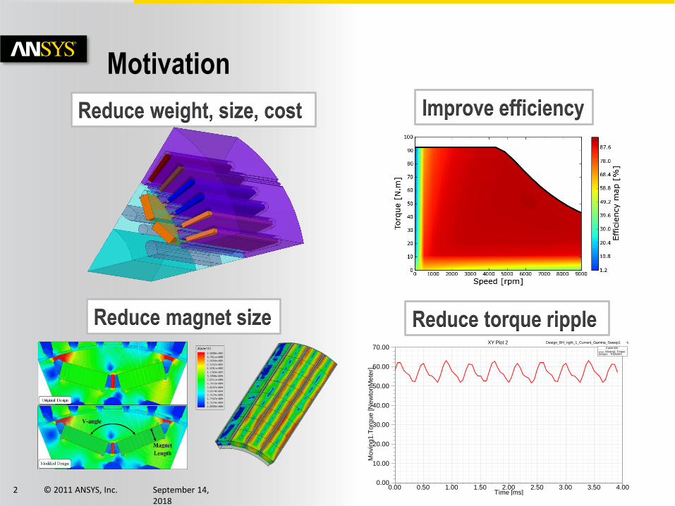
Electrical Machines and Actuators – Design Issues
Function Model
Co-simulation
Field Solution
Geometry
Analytical, System
Electromagnetic
Thermal
Stress, vibration, acoustics
Fatigue, lifetime
© 2011 ANSYS, Inc. September 14, 2018
5
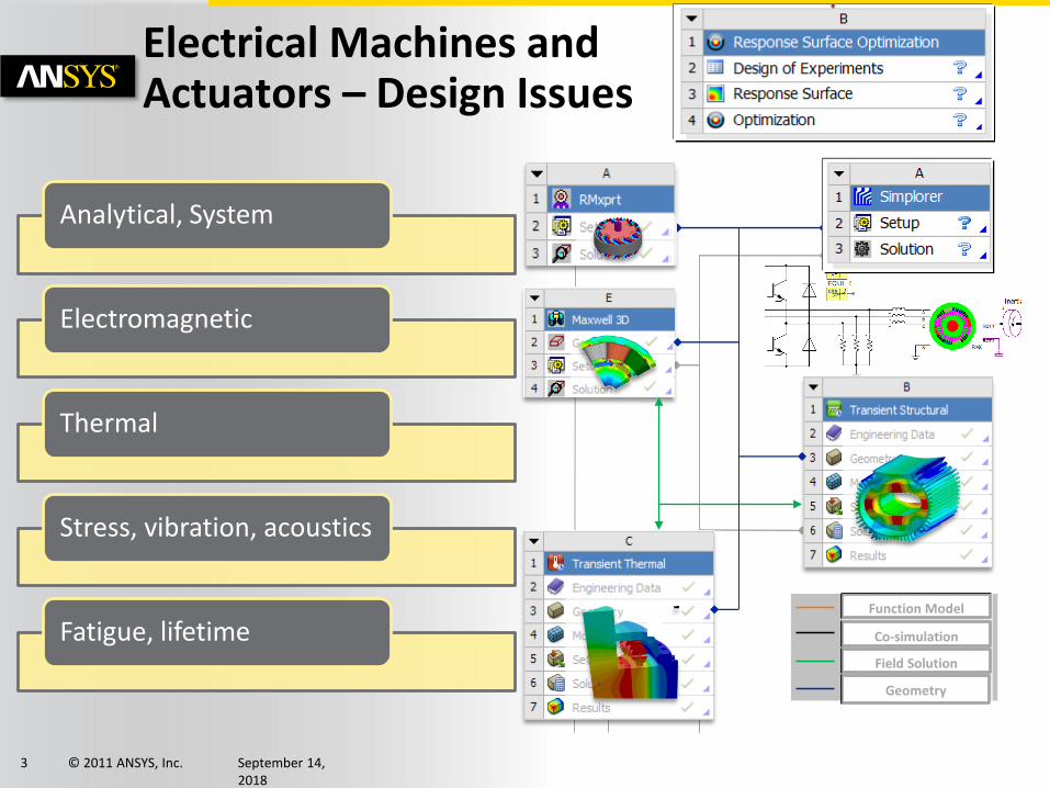
Initial Machine Design
• RMxprt = analytical solution Input data as on data sheet
geometry, winding layout
saturation, core losses
comprehensive results
• machine parameters
• performance curves
© 2011 ANSYS, Inc. September 14, 2018
6
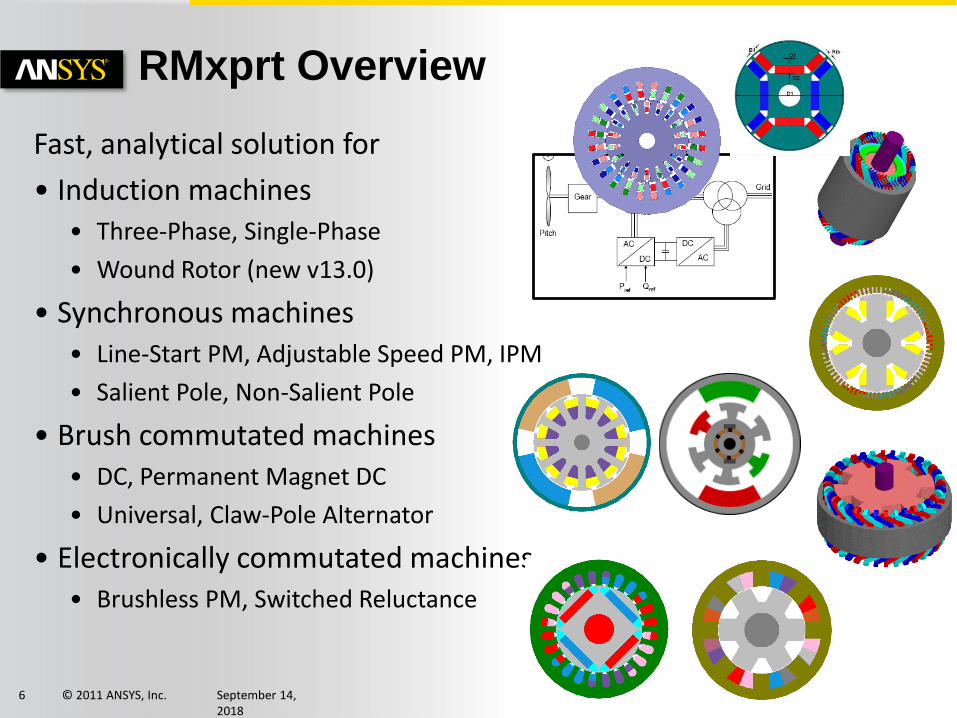
RMxprt Overview
Fast, analytical solution for
• Induction machines • Three-Phase, Single-Phase
• Wound Rotor (new v13.0)
• Synchronous machines• Line-Start PM, Adjustable Speed PM, IPM
• Salient Pole, Non-Salient Pole
• Brush commutated machines• DC, Permanent Magnet DC
• Universal, Claw-Pole Alternator
• Electronically commutated machines• Brushless PM, Switched Reluctance
© 2011 ANSYS, Inc. September 14, 2018
7
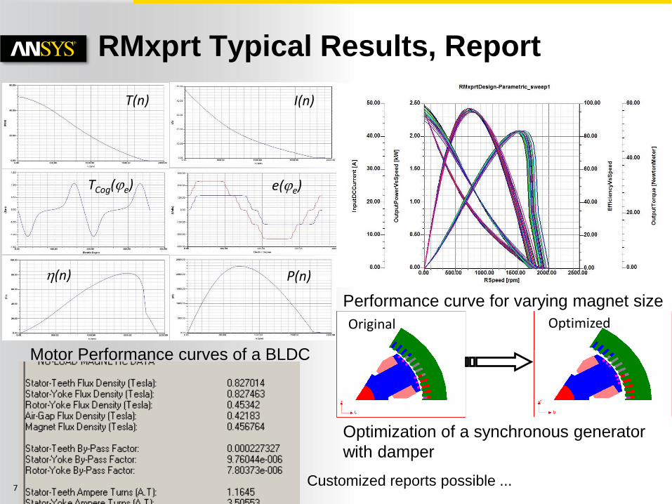
RMxprt Typical Results, Report
Performance curve for varying magnet size
TCog(je)
T(n)
h(n)
I(n)
P(n)
e(je)
Motor Performance curves of a BLDC
Original Optimized
Optimization of a synchronous generator
with damper
Customized reports possible ...
© 2011 ANSYS, Inc. September 14, 2018
9
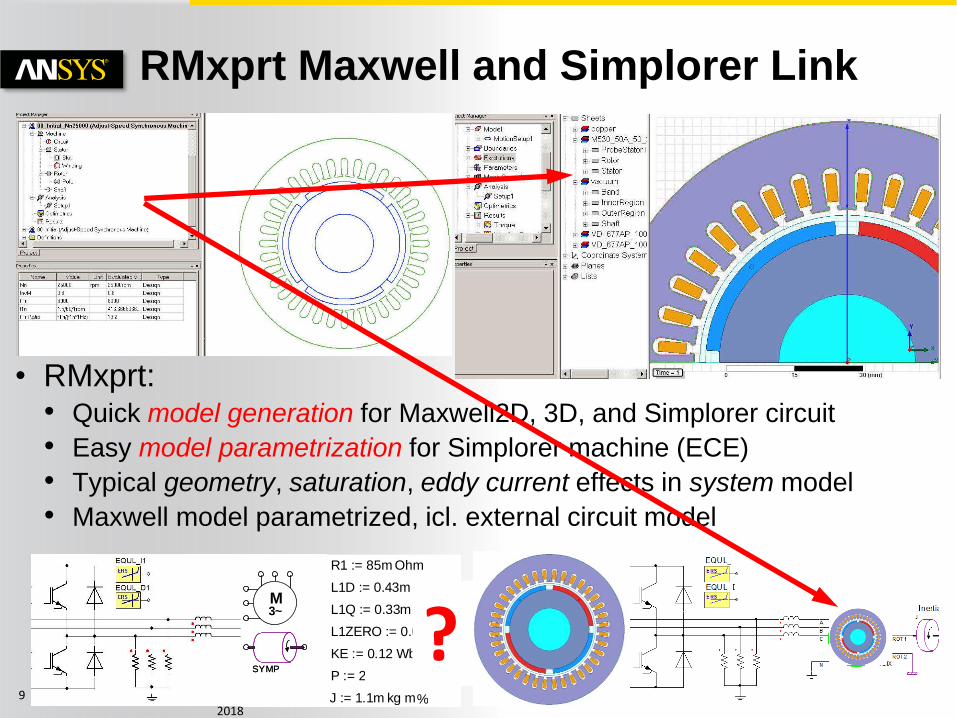
RMxprt Maxwell and Simplorer Link
• RMxprt: • Quick model generation for Maxwell2D, 3D, and Simplorer circuit
• Easy model parametrization for Simplorer machine (ECE)
• Typical geometry, saturation, eddy current effects in system model
• Maxwell model parametrized, icl. external circuit model
3~
SYMP
3~M
SYMP
L1Q := 0.33m H
J := 1.1m kg m%
L1D := 0.43m H
L1ZERO := 0.050m H
R1 := 85m Ohm
P := 2
KE := 0.12 Wb ?
© 2011 ANSYS, Inc. September 14, 2018
10
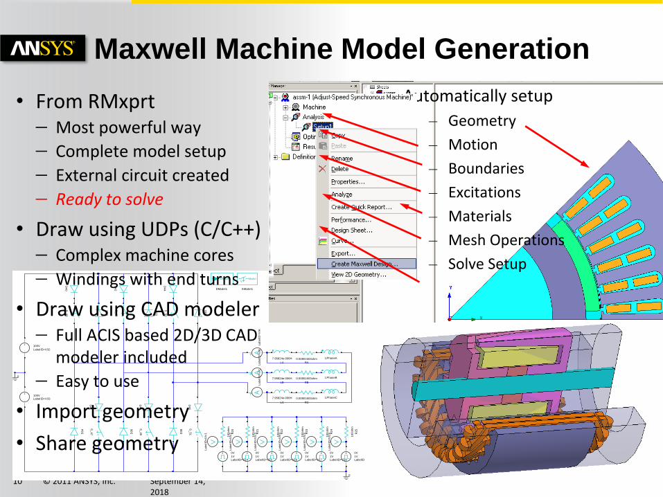
Maxwell Machine Model Generation
0
0
LPhaseA
LPhaseB
LPhaseC
0.00801603ohm
RA
0.00801603ohm
RB
0.00801603ohm
RC
7.95824e-006H
LA
7.95824e-006H
LB
7.95824e-006H
LC
La
be
lID
=V
IAL
ab
elI
D=
VIB
La
be
lID
=V
IC
+ 0V
1VLabelID=V14
+ 0V
1VLabelID=V15
+ 0V
1VLabelID=V16
+ 0V
1VLabelID=V17
+ 0V
1VLabelID=V18
+ 0V
1VLabelID=V19
10
0o
hm
R2
0
10
0o
hm
R2
1
10
0o
hm
R2
2
10
0o
hm
R2
3
10
0o
hm
R2
4
10
0o
hm
R2
5
La
be
lID
=IV
c1
La
be
lID
=IV
c2
La
be
lID
=IV
c3
La
be
lID
=IV
c4
La
be
lID
=IV
c5
La
be
lID
=IV
c6
-
+ 100V
LabelID=V32
-
+100VLabelID=V33
D3
4
D3
5
D3
6
D3
7
D3
8
D3
9
D4
0
D4
1
D4
2
D4
3
D4
4
D4
5
V
S_
46
V
S_
47
V
S_
48
V
S_
49
V
S_
50
V
S_
51
Model
DModel1
ModelV
SModel1
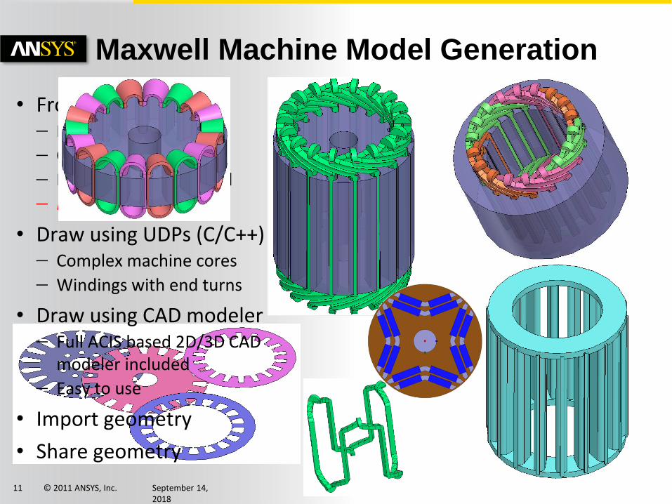
• From RMxprt Most powerful way
Complete model setup
External circuit created
Ready to solve
• Draw using UDPs (C/C++) Complex machine cores
Windings with end turns
• Draw using CAD modeler Full ACIS based 2D/3D CAD
modeler included
Easy to use
• Import geometry
• Share geometry
Automatically setup
– Geometry
– Motion
– Boundaries
– Excitations
– Materials
– Mesh Operations
– Solve Setup
© 2011 ANSYS, Inc. September 14, 2018
11
Maxwell Machine Model Generation
• From RMxprt Most powerful way
Complete model setup
External circuit created
Ready to solve
• Draw using UDPs (C/C++) Complex machine cores
Windings with end turns
• Draw using CAD modeler Full ACIS based 2D/3D CAD
modeler included
Easy to use
• Import geometry
• Share geometry
© 2011 ANSYS, Inc. September 14, 2018
13
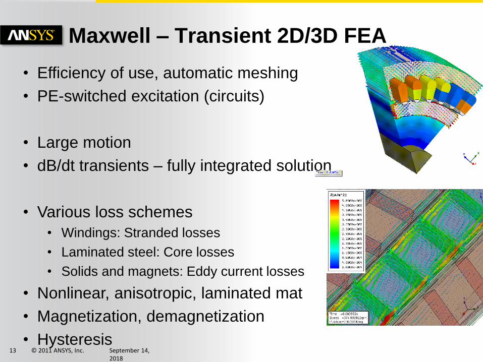
Maxwell – Transient 2D/3D FEA
• Efficiency of use, automatic meshing
• PE-switched excitation (circuits)
• Large motion
• dB/dt transients – fully integrated solution
• Various loss schemes
• Windings: Stranded losses
• Laminated steel: Core losses
• Solids and magnets: Eddy current losses
• Nonlinear, anisotropic, laminated mat
• Magnetization, demagnetization
• Hysteresis
© 2011 ANSYS, Inc. September 14, 2018
14
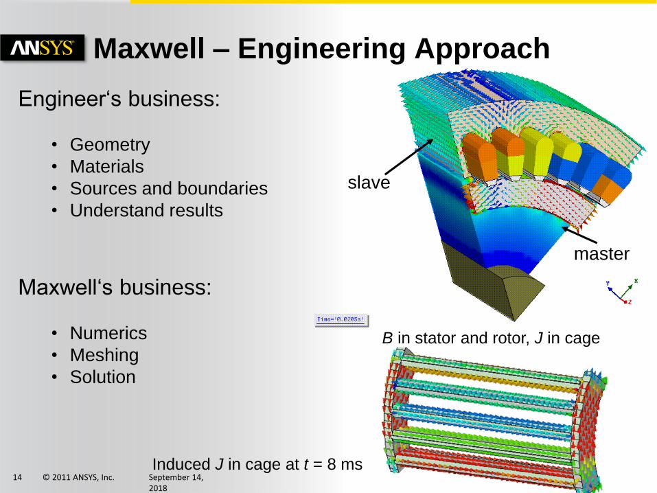
Maxwell – Engineering Approach
Induced J in cage at t = 8 ms
B in stator and rotor, J in cage
master
slave
Engineer‘s business:
• Geometry
• Materials
• Sources and boundaries
• Understand results
Maxwell‘s business:
• Numerics
• Meshing
• Solution
© 2011 ANSYS, Inc. September 14, 2018
16
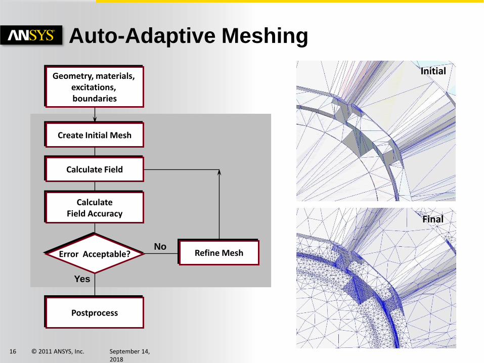
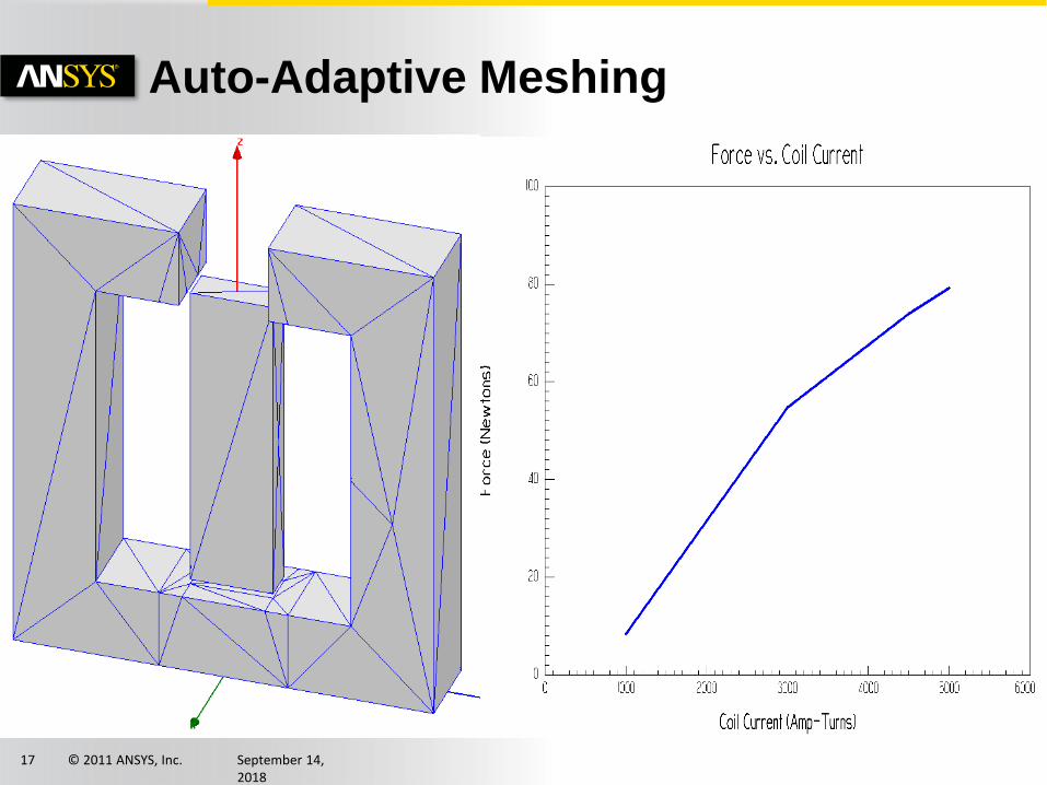
Auto-Adaptive Meshing
Geometry, materials, excitations, boundaries
Create Initial Mesh
Calculate Field
CalculateField Accuracy
Error Acceptable?
Postprocess
No
Yes
Refine Mesh
Initial
Final
© 2011 ANSYS, Inc. September 14, 2018
17
Auto-Adaptive Meshing
© 2011 ANSYS, Inc. September 14, 2018
18
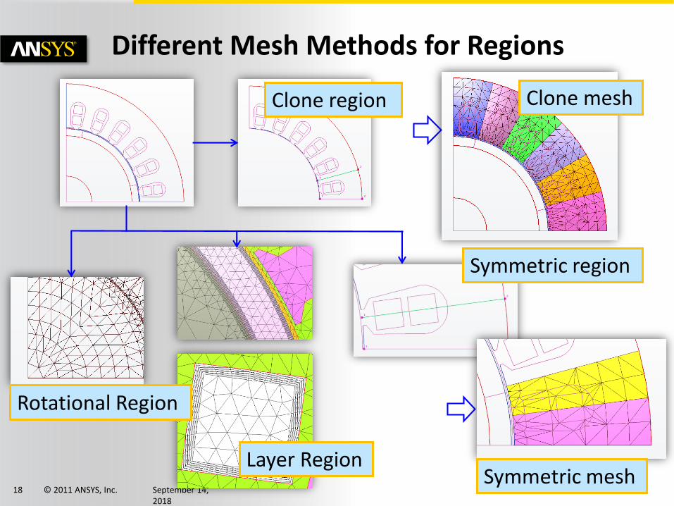
Clone region
Symmetric region
Different Mesh Methods for Regions
Symmetric mesh
Clone mesh
Layer Region
Rotational Region
© 2011 ANSYS, Inc. September 14, 2018
20
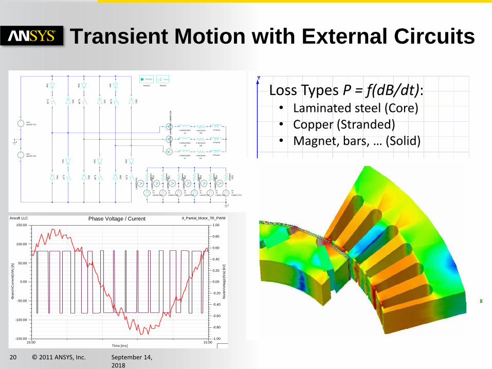
Transient Motion with External Circuits
0
0
LPhaseA
LPhaseB
LPhaseC
2.99132ohm
RA
2.99132ohm
RB
2.99132ohm
RC
0.000921945H
LA
0.000921945H
LB
0.000921945H
LC
LabelID
=V
IALabelID
=V
IBLabelID
=V
IC
+ 0V
1V
LabelID=V14
+ 0V
1V
LabelID=V15
+ 0V
1V
LabelID=V16
+ 0V
1V
LabelID=V17
+ 0V
1V
LabelID=V18
+ 0V
1V
LabelID=V19
100ohm
R20
100ohm
R21
100ohm
R22
100ohm
R23
100ohm
R24
100ohm
R25
LabelID
=IV
c1
LabelID
=IV
c2
LabelID
=IV
c3
LabelID
=IV
c4
LabelID
=IV
c5
LabelID
=IV
c6
-
+ 110V
LabelID=V32
-
+110V
LabelID=V33
D34
D35
D36
D37
D38
D39
D40
D41
D42
D43
D44
D45
V
S_46
V
S_47
V
S_48
V
S_49
V
S_50
V
S_51
Model
DModel1
ModelV
SModel1
10.00 15.00Time [ms]
-1.00
-0.80
-0.60
-0.40
-0.20
0.00
0.20
0.40
0.60
0.80
1.00N
od
eV
olta
ge
(IV
a)
[kV
]
-150.00
-100.00
-50.00
0.00
50.00
100.00
150.00
-Bra
nch
Cu
rre
nt(
VIA
) [A
]
Ansoft LLC 4_Partial_Motor_TR_PWMPhase Voltage / Current
Loss Types P = f(dB/dt): • Laminated steel (Core)• Copper (Stranded)• Magnet, bars, … (Solid)
© 2011 ANSYS, Inc. September 14, 2018
21
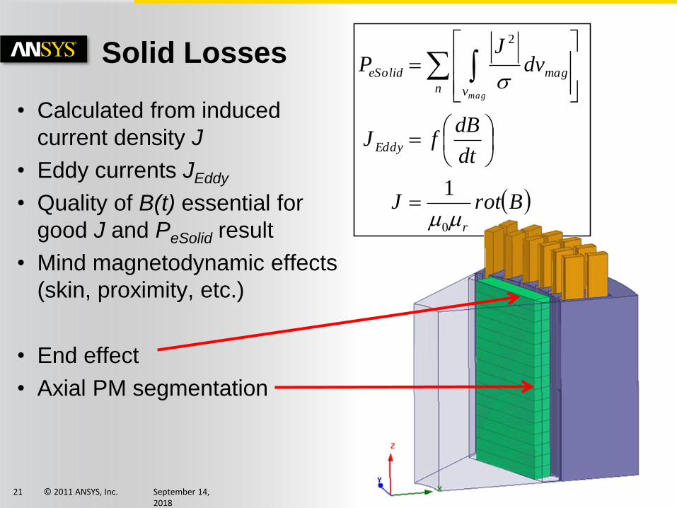
Solid Losses
• Calculated from induced
current density J
• Eddy currents JEddy
• Quality of B(t) essential for
good J and PeSolid result
• Mind magnetodynamic effects
(skin, proximity, etc.)
• End effect
• Axial PM segmentation
BrotJ
dt
dBfJ
dvJ
P
r
Eddy
n
mag
v
eSolid
mag
0
2
1
© 2011 ANSYS, Inc. September 14, 2018
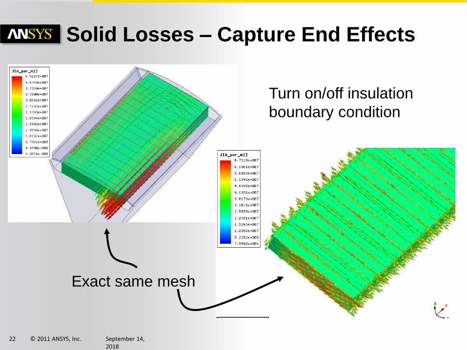
22
Solid Losses – Capture End Effects
Exact same mesh
Turn on/off insulation
boundary condition
© 2011 ANSYS, Inc. September 14, 2018
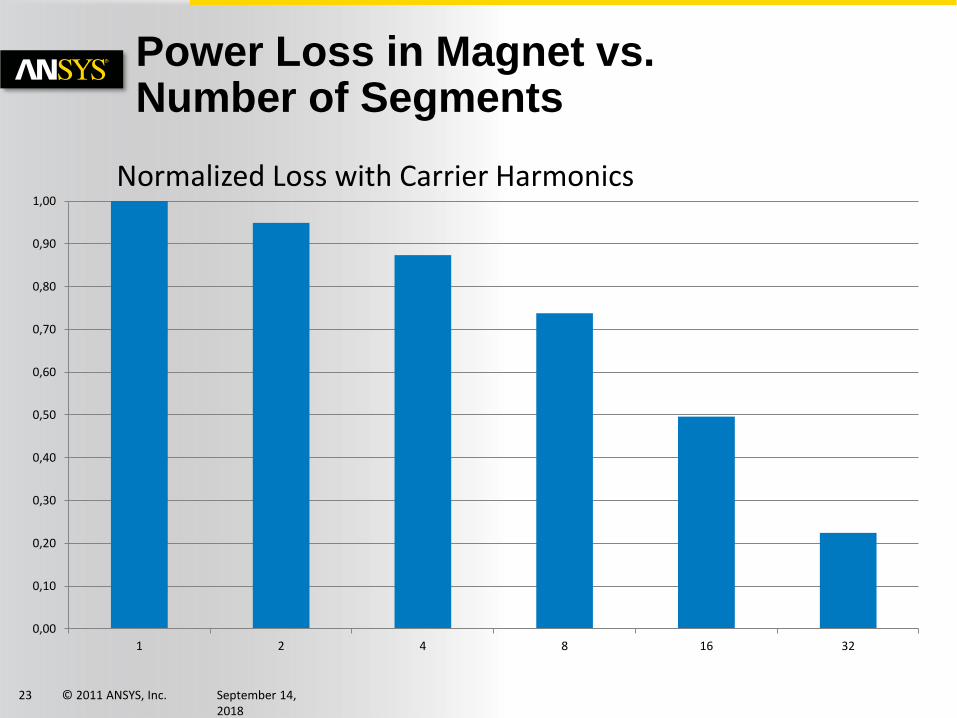
23
Power Loss in Magnet vs. Number of Segments
0,00
0,10
0,20
0,30
0,40
0,50
0,60
0,70
0,80
0,90
1,00
1 2 4 8 16 32
Normalized Loss with Carrier Harmonics
© 2011 ANSYS, Inc. September 14, 2018
24
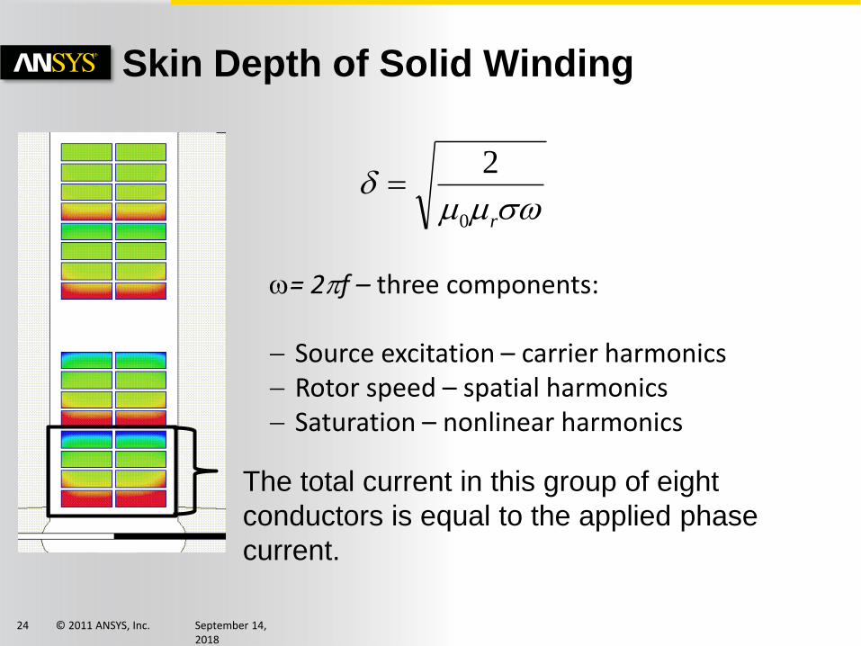
Skin Depth of Solid Winding
r0
2
= 2pf – three components:
Source excitation – carrier harmonics Rotor speed – spatial harmonics Saturation – nonlinear harmonics
The total current in this group of eight
conductors is equal to the applied phase
current.
© 2011 ANSYS, Inc. September 14, 2018
25
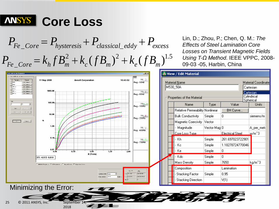
Core Loss
5.122
_ )()( memcmhCoreFe BfkBfkBfkP
excesseddyclassicalhysteresisCoreFe PPPP __
m
i
n
j
mijiemijicmijihvijech
i
BfkBfkBfkpkkkerror11
25.15.1222 )]([),,(Minimizing the Error:
Lin, D.; Zhou, P.; Chen, Q. M.: The
Effects of Steel Lamination Core
Losses on Transient Magnetic Fields
Using T-Ω Method. IEEE VPPC, 2008-
09-03 -05, Harbin, China
© 2011 ANSYS, Inc. September 14, 2018
26
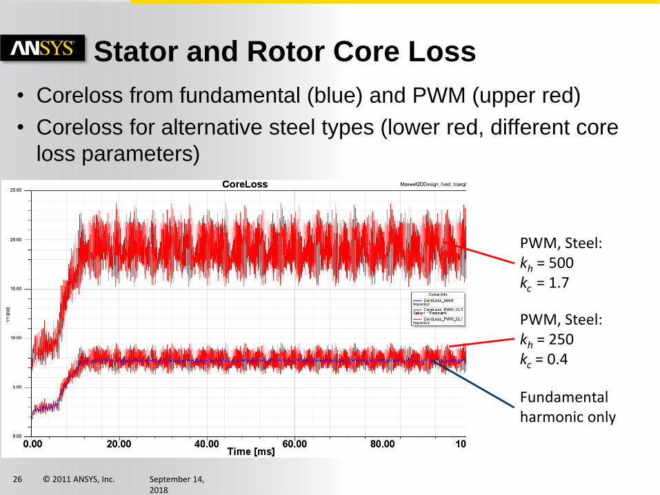
• Coreloss from fundamental (blue) and PWM (upper red)
• Coreloss for alternative steel types (lower red, different core
loss parameters)
Stator and Rotor Core Loss
Fundamental harmonic only
PWM, Steel:kh = 250kc = 0.4
PWM, Steel: kh = 500kc = 1.7
© 2011 ANSYS, Inc. September 14, 2018
27
Vendor sheet data
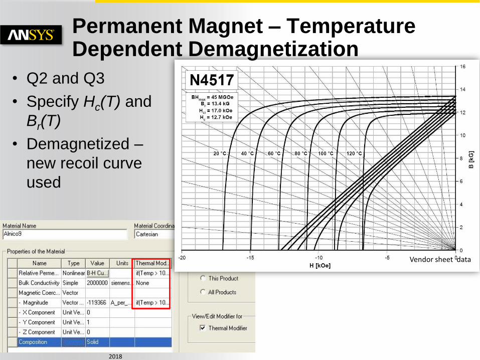
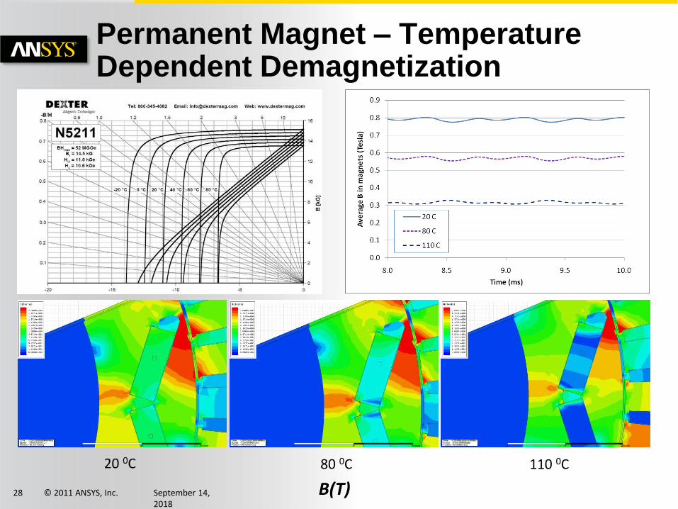
Permanent Magnet – Temperature Dependent Demagnetization
• Q2 and Q3
• Specify Hc(T) and
Br(T)
• Demagnetized –
new recoil curve
used
© 2011 ANSYS, Inc. September 14, 2018
28
Permanent Magnet – Temperature Dependent Demagnetization
B(T)
20 0C 80 0C 110 0C

© 2011 ANSYS, Inc. September 14, 2018
29
Basic Properties
Hx=0 ; Hz=0Mx=0; Mz=0
Hy
My
Maxwell2D/3D Vector Hysteresis
-8
-4
0
4
8
-20 -10 0 10 20
B (k
G)
H (O)
Hysteresis Motor with Solid Rotor
Satisfy All Hystereis Properties
Memory Efficient
Convenient Parameter Identification
Minor Loop handled inherently
© 2011 ANSYS, Inc. September 14, 2018
30
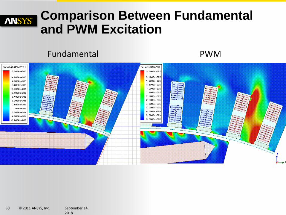
Comparison Between Fundamental and PWM Excitation
Fundamental PWM
© 2011 ANSYS, Inc. September 14, 2018
31
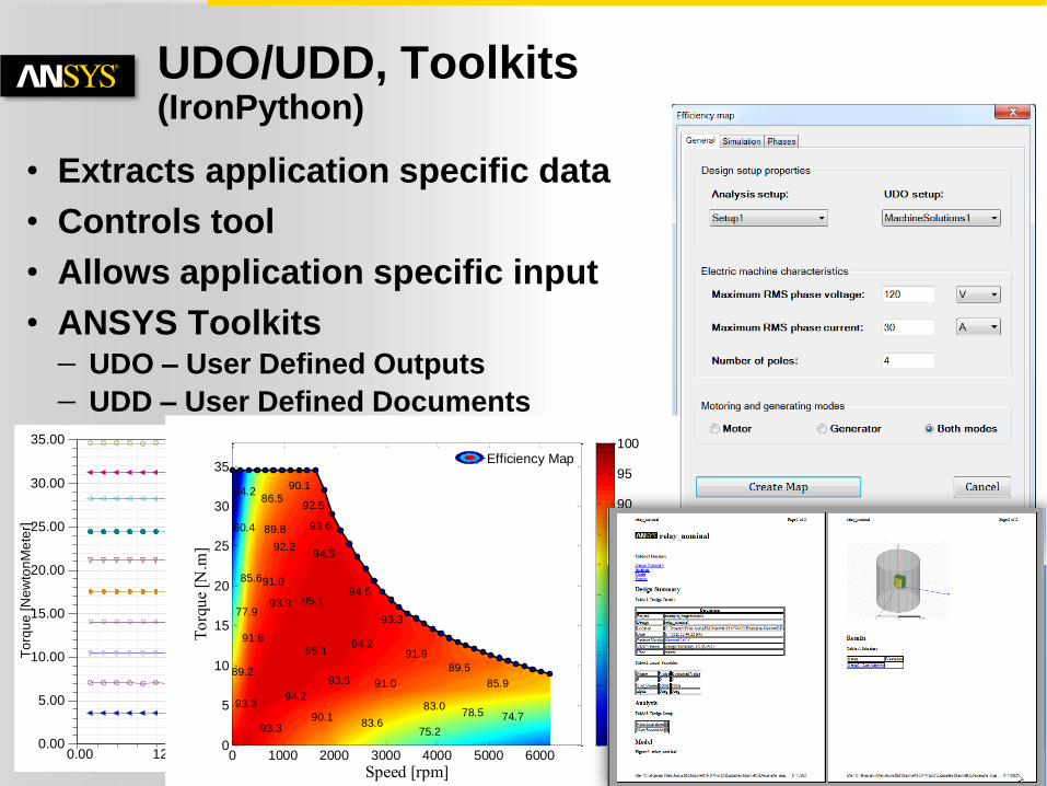
UDO/UDD, Toolkits(IronPython)
0.00 1250.00 2500.00 3750.00 5000.00 6250.00Speed [rpm]
0.00
5.00
10.00
15.00
20.00
25.00
30.00
35.00
To
rqu
e [N
ew
ton
Me
ter]
current_MotorMode_EfficiencyMap2Torque vs Speed MachineSolutions1Gamma_TSC='348.232944deg' Imax_TSC='3.536519818A'
MachineSolutions1Gamma_TSC='6.202690006deg' Imax_TSC='6.29808369A'
MachineSolutions1Gamma_TSC='16.42916617deg' Imax_TSC='9.552484652A'
MachineSolutions1Gamma_TSC='10.27921018deg' Imax_TSC='12.94480651A'
MachineSolutions1Gamma_TSC='354.8801996deg' Imax_TSC='16.74830142A'
MachineSolutions1Gamma_TSC='350.7911592deg' Imax_TSC='20.89757705A'
MachineSolutions1Gamma_TSC='3.605184489deg' Imax_TSC='24.40520948A'
MachineSolutions1Gamma_TSC='347.5926747deg' Imax_TSC='29.84627507A'
MachineSolutions1Gamma_TSC='2.469514124deg' Imax_TSC='35.42019947A'
MachineSolutions1Gamma_TSC='0.007748901848deg' Imax_TSC='42.42453768A'
MachineSolutions1Gamma_TSC='352.7369737deg' Imax_TSC='3.53911626A'
MachineSolutions1Gamma_TSC='23.90892886deg' Imax_TSC='6.447020649A'
MachineSolutions1Gamma_TSC='34.41455762deg' Imax_TSC='10.60675263A'
MachineSolutions1Gamma_TSC='28.26118541deg' Imax_TSC='14.03181228A'
Speed [rpm]
To
rqu
e [N
.m]
94.2
93.6
94.2
94.595.1
95.1
94.5
93.6
92.2
91.085.6
93.9
89.8
92.5
90.186.5
54.2
60.4
77.9
91.6
89.2
93.3
93.390.1
83.6
91.0
91.9
89.5
83.0
75.2
85.9
74.778.5
93.3
0 1000 2000 3000 4000 5000 60000
5
10
15
20
25
30
35
50
55
60
65
70
75
80
85
90
95
100Efficiency Map
• Extracts application specific data
• Controls tool
• Allows application specific input
• ANSYS Toolkits UDO – User Defined Outputs
UDD – User Defined Documents
© 2011 ANSYS, Inc. September 14, 2018
32
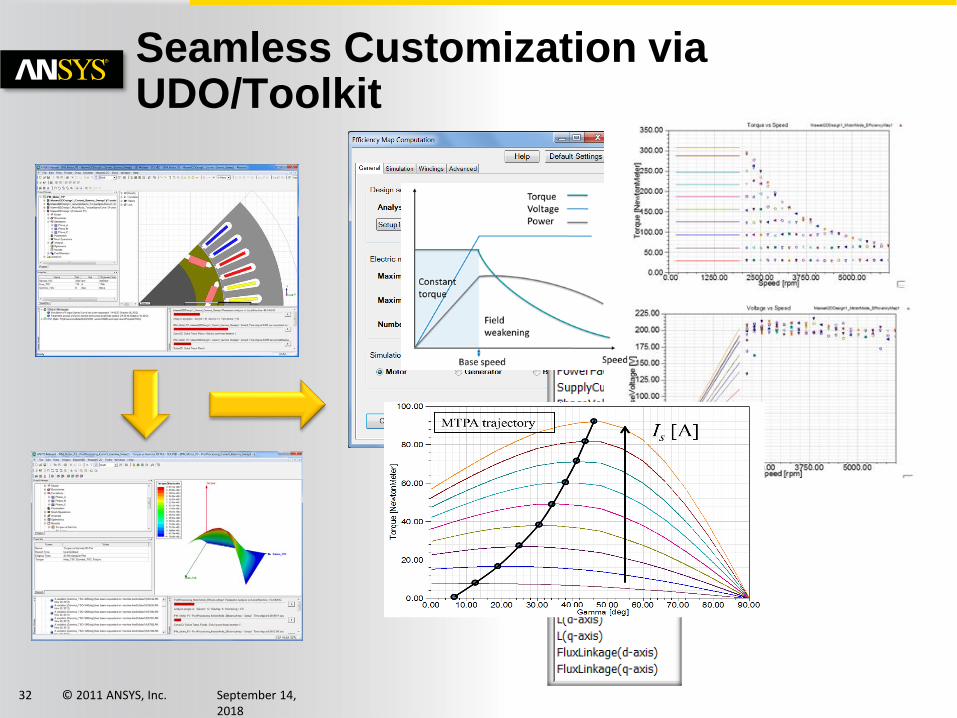
Seamless Customization via UDO/Toolkit
© 2011 ANSYS, Inc. September 14, 2018
33
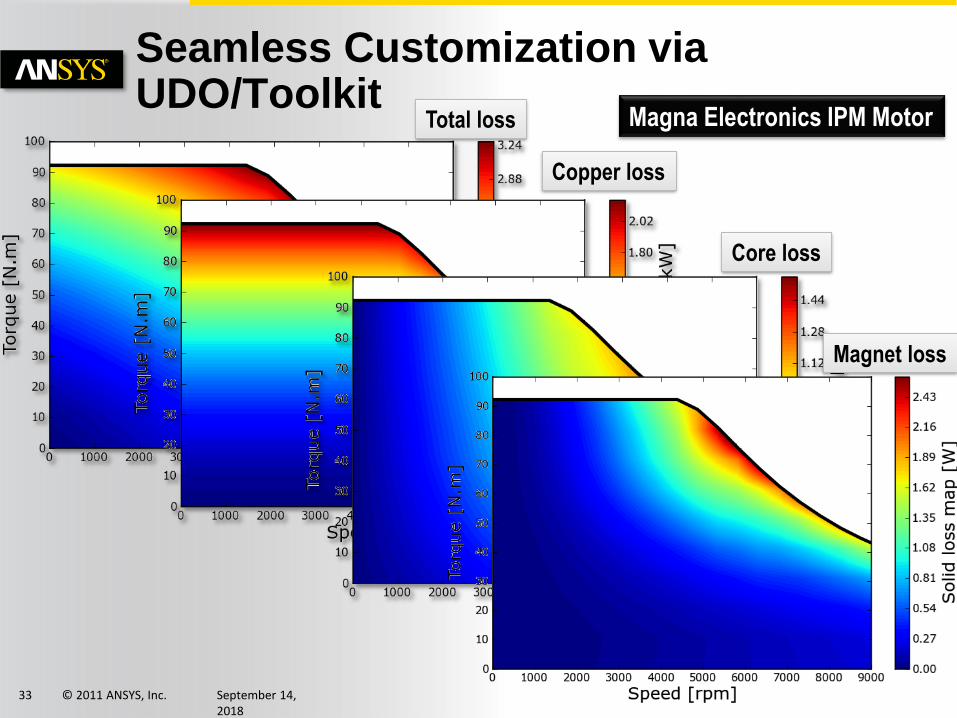
Seamless Customization via UDO/Toolkit
Total loss
Copper loss
Core loss
Magnet loss
Magna Electronics IPM Motor
© 2011 ANSYS, Inc. September 14, 2018
34
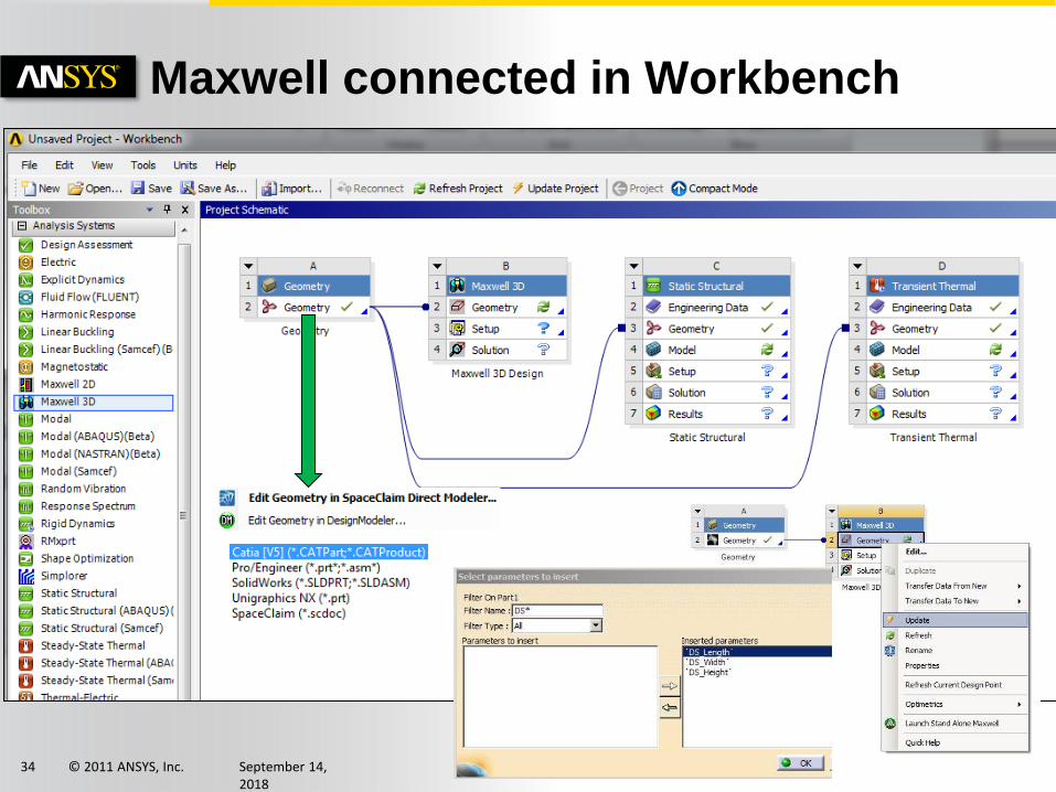
Maxwell connected in Workbench
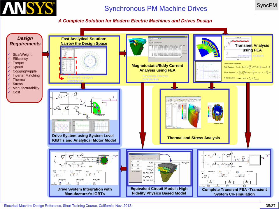
Electrical Machine Design Reference, Short Training Course, California, Nov. 2013. 35/37
Synchronous PM Machine DrivesSyncPM
A Complete Solution for Modern Electric Machines and Drives Design
Equivalent Circuit Model : High
Fidelity Physics Based Model
Fast Analytical Solution:
Narrow the Design Space
Parametric Analysis
Optimization
Magnetostatic/Eddy Current
Analysis using FEA
Parametric Analysis
Optimization
AHA
JA
vV
tcs
sc
f
f
f
f
f uudt
idLiRd
dt
dA
aS
lNd 0
dt
duCi c
f
Field Equation:
Circuit Equation:
Motion Equationexternalem TTm
Simultaneous Equations:
Transient Analysis
using FEA
Parametric Analysis
Drive System Integration with
Manufacturer’s IGBTs
Drive System using System Level
IGBT’s and Analytical Motor Model
Phase CurrentIA.I
IB.I
IC.I
t
1.00k
-1.00k
0
-500.00
500.00
0 17.27m10.00m
Torque
Torque.I
t
400.00
-100.00
0
200.00
0 17.27m10.00m
Phase Voltage
V_AB.V
t
300.00
-300.00
0
-200.00
200.00
0 17.27m10.00m
Von Mises stress
Thermal and Stress Analysis
Complete Transient FEA -Transient
System Co-simulation
Design
Requirements
✓ Size/Weight
✓ Efficiency
✓ Torque
✓ Speed
✓ Cogging/Ripple
✓ Inverter Matching
✓ Thermal
✓ Stress
✓ Manufacturability
✓ Cost

© 2011 ANSYS, Inc. September 14, 2018
36
Electrical Machines and Actuators – Design Issues
Function Model
Co-simulation
Field Solution
Geometry
Analytical, System
Electromagnetic
Thermal
Stress, vibration, acoustics
Fatigue, lifetime