Embed Size (px)
Citation preview

8/13/2019 Elements of Static 00
http://slidepdf.com/reader/full/elements-of-static-00 1/369

8/13/2019 Elements of Static 00
http://slidepdf.com/reader/full/elements-of-static-00 2/369
9<9
/nJ.+ IJ i
\
^
^^fM
I
X*-o i
ii
\
r*/^
%
L -
Q
N
1
i
U
3

8/13/2019 Elements of Static 00
http://slidepdf.com/reader/full/elements-of-static-00 3/369
n

8/13/2019 Elements of Static 00
http://slidepdf.com/reader/full/elements-of-static-00 4/369
*
Presented to the
library
of
the
UNIVERSITY OF TORONTO
from
the estate of
VSRIJOII a. DAVISS

8/13/2019 Elements of Static 00
http://slidepdf.com/reader/full/elements-of-static-00 5/369
BY THE SAME AUTHOR
THE ELEMENTS OF COORDINATE GEOMETRY.Crown 8vo. Complete 12s.
Part I. Cartesian Coordinates. Twenty -fifth Impression. Is.
Part II. Trilinear Coordinates, etc. Third Impression. 6s.
Key to Part I. 10s. net. Key to Part II. 7s. M. net.
THE STRAIGHT LINE AND CIRCLE.
Chapters I-IX of Part I of The Elements of Coordinate Geometry.
Crown 8vo. 4s.
AN ARITHMETIC FOR SCHOOLS.Seventeenth Impression. Globe 8vo. With or without Answers, 5*.
Or in twoParts,
withAnswers,
3s. each. TheExamples alone,
3s. Qd. The Answers alone, Qd.
A NEW EDITION OF DR TODHUNTER'S ALGEBRAFOR BEGINNERS.
Twelfth Impression. Globe 8vo. is. without Answers. 5s. with
Answers. Answers only, Is. 3d. Key, 10s. 6d. net.
A NEW EDITION OF DR TODHUNTER'S EUCLID.Fourth Impression. Globe 8vo. 5s. Also Book I, Is. Bd. Books I
and II, Is. 9d. Books I-IV, 3s. 6d.
With L. W. Grenville, M.A.
A SHILLING ARITHMETIC.
Twenty-second Impression, Revised. Globe 8vo. Is. 6d.With Answers, 2s.
LONDON: MACMILLAN AND CO., Limited

8/13/2019 Elements of Static 00
http://slidepdf.com/reader/full/elements-of-static-00 6/369
BY THE SAME AUTHOR
A TREATISE ON ELEMENTARY DYNAMICS.Crown 8vo. Twelfth Impression. Is. 6d.
SOLUTIONS OF THE EXAMPLES IN ELEMENTARYDYNAMICS.Crown 8vo. 8s. 6d.
THE ELEMENTS OF STATICS AND DYNAMICS.Extra Foolscap 8vo.
Part I. Elements of Statics. Twentieth Impression. 5s. &d.
Part II. Elements of Dynamics. Nineteenth Impression. 5s.
The two Parts bound in one volume. 10s.
SOLUTIONS OF THE EXAMPLES IN THE ELEMENTSOF STATICS AND DYNAMICS.Extra Foolscap 8vo. 9s.
MECHANICSAND HYDROSTATICS FOR REGINNERS.Extra Foolscap 8vo. Twenty-second Impression. 5s.
PLANE TRIGONOMETRY.Crown 8vo. Eighteenth Impression. 10s.
Or in two Parts.
Part I. Up to and Including the Solution of Triangles. 6s.Part II. De Moivre's Theorem and the Higher Portions.
Thirteenth Impression. 5s.
SOLUTIONS OF THE EXAMPLES IN THE PLANETRIGONOMETRY.Crown 8vo. In two Parts. Part I, 10s. 6d. Part II, 7s. Qd.
THE ELEMENTS OF TRIGONOMETRY, WITH FOUR-FIGURE LOGARITHM TABLES.
Extra Foolscap 8vo. Eighth Impression. 4s. 6d.
THE ELEMENTS OF HYDROSTATICS.Being a Companion Volume to The Elements of Statics & Dynamics.Extra Foolscap 8vo. Tenth Impression. 5s. Qd.
SOLUTIONS OF THE EXAMPLES IN THE ELEMENTSOF HYDROSTATICS.Extra Foolscap 8vo. 6s.
DYNAMICS OF A PARTICLE AND OF RIGID BODIES.Demy 8vo. Sixth Impression. 14s.
SOLUTIONS OF THE EXAMPLES IN DYNAMICS OFA PARTICLE AND OF RIGID BODIES.Demy 8vo. 17s. 6d.
AN ELEMENTARY TREATISE ON STATICS.
Demy 8vo. Sixth Impression. 14s.
CAMBRIDGE UNIVERSITY PRESSLONDON Fetter Lane, e.c. 4

8/13/2019 Elements of Static 00
http://slidepdf.com/reader/full/elements-of-static-00 7/369
Pitt Press Mathematical Series
THE ELEMENTS
OF
STATICS AND DYNAMICS.
PART I. ELEMENTS OF STATICa

8/13/2019 Elements of Static 00
http://slidepdf.com/reader/full/elements-of-static-00 8/369
Cambridge University Press
Fetter Lane, London
New York
Bombay, Calcutta, Madras
Toronto
Macmillan
Tokyo
Maruzen Company, Ltd
All rights reserved

8/13/2019 Elements of Static 00
http://slidepdf.com/reader/full/elements-of-static-00 9/369
THE ELEMENTS
OF
STATICS AND DYNAMICS
BY
S. L. LONEY, M.A.
LATE PROFESSOR OF MATHEMATICS AT THE ROYAL HOLLOWAY COLLKOB
(UNIVERSITY OF LONDON),
SOMETIME FELLOW OF SIDNEY SUSSEX COLLEGE, CAMBRIDGE.
PART I. STATICS.
FIFTH EDITION
(TWENTY-FIRST IMPRESSION)
CAMBRIDGE :
AT THE UNIVERSITY PRESS
1932

8/13/2019 Elements of Static 00
http://slidepdf.com/reader/full/elements-of-static-00 10/369
First Edition, Dec. 1890.
Second Edition, Sept. 1892,
Third Edition, June, 1893.
Fourth Edition, enlarged, Jan. 1895.
Reprinted1897,
1899, 1900, 1902,1904.
Fifth Edition (revised and enlarged), July, 1901).
Reprinted 1907, 1908, 1911, 1914, 1918, 1920(twice)
1923, 1925, 1927, 1932
PRINTED IN GREAT BRITAIN

8/13/2019 Elements of Static 00
http://slidepdf.com/reader/full/elements-of-static-00 11/369
PREFACE TO PART I.
TN the following work I have aimed at writing a
-*-working text-book on Statics for the use of Junior
Students.
Throughout the book will be found a large numberof examples ;
most of them, with the exception of
many of those at the end of the Chapter on Friction
and the Miscellaneous Examples at the end of the
volume, are of an easy type.
I have tried to make the book complete as far as
it goes; it is suggested, however, that the student
should, on the first reading of the subject, omit every-
thing marked with an asterisk.
I must express my obligations to my friend
Mr H. C.
Eobson, M.A.,Fellow
and Lecturer of
Sidney Sussex College, Cambridge, for his kindness
in reading through the proof-sheets, and for many
suggestions that he has made to me.
Any corrections of errors, or hints for improvement
will be
thankfully
received.
S. L. LONEY.Barnes, S.W.
December, 1890.

8/13/2019 Elements of Static 00
http://slidepdf.com/reader/full/elements-of-static-00 12/369
PEEFACE TO THE TENTH EDITION.
THEbook has been somewhat altered, and I hope
improved, for this edition, and the type entirely
re-set. Graphic solutions have been introduced much
earlier, and more use has been made of graphic methods
throughout the book. More experimental work has also
been introduced.
The chapter on Work has been placed earlier, and
much greater stress has been laid upon the Principle of
Work.
Sundry somewhat long analytical proofs have been
relegated to the last chapter, and here I have not
scrupled to introduce alternative proofs involving the
use of the Differential Calculus.
For ten of the new figures in this book I am much
indebted to the kindness and courtesy of Dr R. T.
Glazebrook, who allowed me to use the blocks prepared
for his Statics. Most of these figures have the additional
merit of having been drawn from actual apparatus in
use at the Cavendish Laboratory at Cambridge.
S. L. LONEY.
KoYAl. HoLLOWAY CoLliEGE
Eng^efieldGkeen,
Subbey.
July 23rd, 1906.

8/13/2019 Elements of Static 00
http://slidepdf.com/reader/full/elements-of-static-00 13/369
CONTENTS.
STATICS.CHAP. PAGK
I. Introduction 1
II. Composition and Resolution of Forces . . 8
III. Composition and Resolution of Forces (con-
tinued)29
IV. Parallel Forces 47
V. Moments 58
VI. Couples 75
VII. Equilibrium of a rigid body acted upon by
THREE FORCES IN A PLANE
....84
VIII. General conditions of equilibrium of a rigid
BODY ACTED ON BY A SYSTEM OF FORCES IN
ONE PLANE 97
IX. Centre of Gravity 119
Centre of gravity of a Triangle, Tetrahedron,
etc 123
General formulae for the determination of the
centre of gravity129
X. Centre of Gravity (continued).
Properties of the centre of gravity . . .149
Stable and unstable equilibrium . . . 153
XI. Wore. .... .... 163

8/13/2019 Elements of Static 00
http://slidepdf.com/reader/full/elements-of-static-00 14/369
CONTENTS.
CHAP.
XII. Machines 171
I. The Lever 174
II. Pulleys and Systems of Pulleys . . 180
III. The Inclined Plane . . . .196
IV. The Wheel and Axle . . . .203
Weston's Differential Pulley . . 207
The Common Balance .... 209
The Steelyards218
The Screw 224
232
. 233
. 241
. 246
. .248
V.
VI.
VII.
XIII. Friction
Laws of Friction
Equilibrium on a rough Inclined Plane .
Efficiency of machines .....Machines with friction
XIV. Problems with Friction 260
XV. Miscellaneous.
Smooth Hinges 274
Funicular Polygon 279
Tensions of Elastic Strings .... 282
Graphic Constructions. Link and Force Poly-
gons
XVI. Some Additional Propositions ....Formal proof of the Parallelogram of Forces .
Centre of gravity of a Circular Arc, and of a
Sector and Segment of a Circle
Centre of gravity of a Zone of a Sphere
Centres of gravity of a Hollow and a Solid
Hemisphere 308
Virtual Work 310
Roberval's Balance 314
Easy Miscellaneous Examples 318
Harder Miscellaneous Examples 320
Answers . . . i xx
286
297
297
301
305

8/13/2019 Elements of Static 00
http://slidepdf.com/reader/full/elements-of-static-00 15/369
STATICS.
CHAPTER I.
INTRODUCTION.
1. A Body is a portion of matter limited in every
direction.
2. Force is anything which changes, or tends to
change, the state of rest, or uniform motion, of a body.
3. Rest. A body is said to be at rest when it does
not change its position with respect to surrounding objects.
4. Statics is the science which treats of the action
of forces on bodies, the forces being so arranged that the
bodies are at rest.
The science which treats of the action of force on bodies
in motion is called Dynamics.
In the more modern system of nomenclature which is gradually
gaining general acceptance, the science which treats of the action offorce on bodies is called Dynamics, and it has two subdivisions,
Statics and Kinetics, treating of the action of forces on bodies which
are at rest and in motion respectively.
5. A Particle is a portion of matter which is in-
definitely small in size, or which, for the purpose of our
investigations, is so small that the distances between its
different parts may be neglected.
L. S. 1

8/13/2019 Elements of Static 00
http://slidepdf.com/reader/full/elements-of-static-00 16/369
2 STATICS
A body may be regarded as anindefinitely large number
of indefinitely small portions, or as a conglomeration of
particles.
6. A Rigid Body is a body whose parts always
preserve an invariable position with respect to one another.
This conception, like that of a particle, is idealistic.
In nature no body is perfectly rigid. Every body yields,
perhaps only very slightly, if force be applied to it. If a
rod, made of wood, have one end firmly fixed and the other
end be pulled, the wood stretches slightly if the rod be
made of iron the deformation is very much less.
To simplify our enquiry we shall assume that all the
bodies with which we have to deal are perfectly rigid.
7.
EqualForces. Two forces are said to be
equalwhen, if they act on a particle in opposite directions, the
particle remains at rest.
8. Mass. The mass of a body is the quantity of
matter in the body. The unit of mass used in England is
a pound and is defined to be the mass of a certain piece of
platinum kept in the Exchequer Office.
Hence the mass of a body is two, three, four... lbs.,
when it contains two, three, four... times as much matter
as the standard lump of platinum.
In France, and other foreign countries, the theoretical
unit of mass used is a gramme, which is equal to about
15*432 grains. The practical unit is a kilogramme (1000
grammes), which is equal to about 2*2046 lbs.
9. Weight. The idea of weight is one with which
everyone is familiar. We all know that a certain amount
of exertion is required to prevent any body from falling to
the ground. The earth attracts every body to itself with

8/13/2019 Elements of Static 00
http://slidepdf.com/reader/full/elements-of-static-00 17/369
INTRODUCTION 3
a force which, as we shall see in Dynamics, is proportional
to the mass of the body.
The force with which the earth attracts any bodyto
itself is called the weight of the body.
10. Measurement of Force. We shall choose, as our
unit of force in Statics, the weight of one pound. The unit
of force is therefore equal to the force which would just
support a mass of one pound when hanging freely.
We shall find in Dynamics that the weight of one
pound is not quite the same at different points of the
earth's surface.
In Statics, however, we shall not have to compare forces
at different points of the earth's surface, so that this variation
in the weight of a pound is of no practical importance ;we
shall therefore neglect this variation and assume the weight
of a pound to be constant.
11. In practice the expression weight of one pound
is, in Statics, often shortened into one pound. The
student will therefore understand that a force of 10 lbs.
means a force equal to the weight of 10 lbs.
12. Forces represented by straight lines. A force will
be completely known when we know(i)
its magnitude,
(ii)its direction, and
(iii)its point of application, i.e. the
point of the body at which the force acts.
Hence we canconveniently represent
a force
bya
straight line drawn through its point of application; for
a straight line has both magnitude and direction.
Thus suppose a straight line OA represents a force,
equal to 10 lbs. weight, acting at a point 0. A force of
5 lbs. weight acting in the same direction would be repre-
sented
by 0,where B bisects the distance
OA,whilst a
12

8/13/2019 Elements of Static 00
http://slidepdf.com/reader/full/elements-of-static-00 18/369
i STATICS
force, equal to 20 lbs. weight, would be represented by OC,where OA is produced till AC equals OA.
An arrowhead is often used to denote the direction in
which a force acts.
13. Subdivisions of Force. There are three different
forms under which a force may appear when applied to a
mass, viz. as(i)
an attraction, (ii)a tension, and
(iii)a
reaction.
14. Attraction. An attraction is a force exerted by
one body on another without the intervention of any
visible instrument and without the bodies being necessarily
in contact. The only example we shall have in this book
is the attraction which the earth has for every body ;this
attraction is (Art. 9)called its weight.
15. Tension. If we tie one end of a string to any
point of a body and pull at the other end of the string, we
exert a force on the body ;such a force, exerted by means
of a string or rod, is called a tension.
If the string be light [i.e.one whose weight is so small
that it may be neglected]the force exerted by the string is
the same throughout its length.
For example, if a weight W be
supported by means of a light
string passing over the smooth
edge of a table it is found that the
same force must be applied to the
T
W

8/13/2019 Elements of Static 00
http://slidepdf.com/reader/full/elements-of-static-00 19/369
INTRODUCTION 5
string whatever be the point, A, 2>,or C of the string at
which the force is applied.
Now the force at A required to support the weight
is the same in each case;hence it is clear that the effect
at A is the same whatever be the point of the string to
which the tension is applied and that the tension of the
string is therefore the same throughout its length.
Again, if the weight W be sup-
ported by a light string passing round
a smooth peg A, it is found that the
same force must be exerted at the other
end of the string whatever be the
direction (AB, AC, or AD) in which
the string is pulled and that this force
is equal to the weight W.
[Theseforces may be measured by attaching the free
end of the string to aspring-balance.]
Hence the tension of a light string passing round a
smooth peg is the same throughout its length.
If two or more strings be knotted
together
the tensions
are not necessarily the same in each string.
The student must carefully notice that the tension of a string is
not proportional to its length. It is a common error to suppose that
the longer a string the greater is its tension; it is true that we can
often apply our force more advantageously if we use a longer piece of
string, and hence a beginner often assumes that, other things being
equal, the longer string has the greater tension.
16. Reaction. If one body lean, or be pressed, against
another body, each body experiences a force at the point of
contact;such a force is called a reaction.
The force, or action, that one body exerts on a second
body is equal and opposite to the force, or reaction, that
the second body exerts on the first.

8/13/2019 Elements of Static 00
http://slidepdf.com/reader/full/elements-of-static-00 20/369
6 STATICS
This statement will be found to be included in Newton's
Third Law of Motion [Part II., Art. 73].
Examples. If a ladder lean against a wall the force
exerted by the end of the ladder upon the wall is equal and
opposite to that exerted by the wall upon the end of the
ladder.
If a cube of wood is placed upon a table the force which
it exerts upon the table is equal and opposite to the force
which the table exerts on it.
17. Equilibrium. When two or more forces act
upon a body and are so arranged that the body remains at
rest, the forces are said to be in equilibrium.
18. Introduction, or removal, of equal and opposite
forces.
We shall assume that if at
any pointof a
rigid
body we apply two equal and opposite forces, they will
have no effect on the equilibrium of the body; similarly,
that if at any point of a body two equal and opposite
forces are acting they may be removed.
19. Principle of the Transmissibility of Force. If a
force act at any point of a rigid body, it may be considered
to act at any other point in its line of action provided that
this latter point be rigidly connected with the body.
Let a force F act at a point A of a body in a direction
AX. Take any point B in AX and at B introduce two

8/13/2019 Elements of Static 00
http://slidepdf.com/reader/full/elements-of-static-00 21/369
INTRODUCTION- 7
equal and opposite forces, each equal to F, acting in the
directions BA and BX;these will have no effect on the
equilibrium of the body.
The forces F acting at A in the direction AB, and F at
B in the direction BA are equal and opposite; we shall
assume that they neutralise one another and hence that
they may be removed.
We have thus left the force F at B acting in the
direction BX and its effect is the same as that of the
original force F at A.
The internal forces in the above body would be different
according as the force F is supposed applied at A or B;
of the internal forces, however, we do not treat in the
present book.
20. Smooth bodies. If we place a piece of smooth
polished wood, having a plane face, upon a table whose top
is made as smooth as possible we shall find that, if we
attempt to move the block along the surface of the table,
some resistance is experienced. There is always some
force, however small, between the wood and the surface
of the table.
If the bodies were perfectly smooth there would be
no force, parallel to the surface of the table, between the
block and the table; the only force between them would
be perpendicular to the table.
Def. When two bodies, which are in contact, are
perfectly smooth the force, or reaction, between them is
perpendicular to their common surface at the point of
contact.

8/13/2019 Elements of Static 00
http://slidepdf.com/reader/full/elements-of-static-00 22/369
CHAPTER II.
COMPOSITION AND RESOLUTION OF FORCES.
21. Suppose a flat piece of wood is resting on a
smooth table and that it is pulled by means of three strings
attached to three of its corners, the forces exerted by the
strings being horizontal ; if the tensions of the strings beso adjusted that the wood remains at rest it follows that
the three forces are in equilibrium.
Hence two of the forces must together exert a force
equal and opposite to the third. This force, equal and
opposite to the third, is called the resultant of the first two.
22. Resultant. Def. If two or moreforces P, Q,
S. . . act upon a rigid body and if a single force, R, can be
found whose effect upon tlie body is tlie same as that of tlie
forces P, Q, S... this single force R is called tlie resultant of
tlie oilier forces and the forces P} Q, S... are called tlie com-
ponents of R.
It follows from the definition that if a force be applied
to the body equal and opposite to the force R, then the
forces acting on the body will balance and the body be in
equilibrium ; conversely, if the forces acting on a body
balance then either of them is equal and opposite to the
resultant of the others.

8/13/2019 Elements of Static 00
http://slidepdf.com/reader/full/elements-of-static-00 23/369
COMPOSITION AND RESOLUTION OF FORCES 9
23. Resultant offorces acting in the same straigM line.
If two forces act on a body in the same direction their
resultant is
clearly equal
to their sumj
thus two forces
acting in the same direction, equal to 5 and 7 lbs. weight
respectively, are equivalent to a force of 12 lbs. weight
acting in the same direction as the two forces.
If two forces act on a body in opposite directions their
resultant is equal to their difference and acts in the direction
of thegreater;
thus two forces
acting
in
opposite
directions
and equal to 9 and 4 lbs. weight respectively are equivalent
to a force of 5 lbs. weight acting in the direction of the
first of the two forces.
24. When two forces act at a point of a rigid body in
different directions their resultant may be obtained by
means of the following
Theorem. Parallelogram of Forces. If tivo
forces, acting at a point, be represented in magnitude and
direction by the hvo sides of a parallelogram drawnfrom one
of its angular points, their resultant is represented both in
magnitude and direction by the diagonal of the parallelogram
passing through that angular point.
This fundamental theorem of Statics, or rather another
form of it, viz. the Triangle of Forces (Art. 36), was first
enunciated by Stevinus of Bruges in the year 1586. Before
his time the science of Statics rested on the Principle of
the Lever as its basis.
In the following article we shall give an experimental
proof; a more formal proof will l>e found in the last chapter.
In Art. 72 of Part II. of this book will be found a proof
founded on Newton's Laws of Motion.
25. Experimental proof. Let F and G be two
light pulleys attached to a fixed support; over them let

8/13/2019 Elements of Static 00
http://slidepdf.com/reader/full/elements-of-static-00 24/369
10 STATICS
there pass two light strings tied together at 0, and carrying
scale-pans L and M at their other ends.
A second string is knotted at and carries a third
scale-pan N.
Into these
scale-pans
are
placedknown
weights,and the
whole system is allowed to take up a position of equilibrium.
Let the weights in the scale-pans, together with the weights
of the scale-pans themselves, be P, Q and R lbs. respectively.
On a blackboard, or a piece of paper, conveniently
placed behind the system draw the lines OF, 00, ON as in
the figure.

8/13/2019 Elements of Static 00
http://slidepdf.com/reader/full/elements-of-static-00 25/369
COMPOSITION AND RESOLUTION OF FORCES 1 1
Taking some convenient scale (say three inches, or less,
per one lb.)mark off OA, OB, and OB to represent P, Q,
and
Rlbs.
Completethe
parallelogramOACB. Then OC
will be found to be equal in length, and opposite in direction,
to OB.
But, since P, Q, and R balance, therefore R must be
equal and opposite to the resultant of P and Q.
Therefore the resultant of P and Q is represented by
0C}
i.e.
bythe
diagonal
of the
parallelogram
whose sides
represent P and Q.
This will be found to be true whatever be the relative
magnitudes of P, Q, and R, provided only that one of them
is not greater than the sum of the other two.
In the figure P, Q, and R are taken respectively to be 4, 3, and
5 lbs. In this case, since 52=42+ 32,the angle AOB is a right
angle.
When the experiment is performed, it will probably be
found that the point may be moved into one of several
positions close to one another. The reason for this is that
we cannot wholly get rid of the friction on the pivots of the
pulleys.The effect of this friction will be minimised, in
this and similar statical experiments, if the pulleys are of
fairly large diameter; aluminium pulleys are suitable be-
cause they can be made of comparatively large size and yet
be of small weight.
Apparatus of the solid type shewn in the above figure
is not necessary for a rough experiment. The pulleys Fand G may have holes bored through them through which
bradawls can be put ;these bradawls may then be pushed
into a vertical blackboard.
The pulleys and weights of the foregoing experiment may be
replaced by three Salter's Spring Balances. Each of these balances
shews, by a pointer which travels up and down a graduated face, whatforce is applied to the hook at its end.

8/13/2019 Elements of Static 00
http://slidepdf.com/reader/full/elements-of-static-00 26/369
12 STA TICS
Three light strings are knotted at O and attached to the ends of
the spring balances. The three balances are then drawn out to shew-
any convenient tensions, and laid on a horizontal table and fixed to it
byhooks or nails as shewn. The
readingsof the
balances then givethe tensions P, Q, and B of the three strings. Just as in the
0^ VN C
preceding experiment we draw lines OA, OB, and OC to represent
P, Q, and B on any scale that is convenient, and then verify that OC
is equal in magnitude and exactly opposite in direction to OD, the
diagonal of the parallelogram of which OA and OB are adjacent
sides.
26. To find the direction and magnitude of the re-
sultant of two forces, we have to find the direction and
magnitude of the diagonal of a parallelogram of which the
two sides represent the forces.
Ex. 1. Find the resultant of forces equal to 12 and 5 lbs. weight
respectively acting at right angles.
B ^C

8/13/2019 Elements of Static 00
http://slidepdf.com/reader/full/elements-of-static-00 27/369
COMPOSITION AND RESOLUTION OF FORGES 13
Let OA and OB represent the forces so that OA is 12 units of
length and OB is 5 units of length; complete the rectangle OACB.
Then OC2=0^'2 + ^C2=122+ 52 =169. .-. 0C=13.
5
Also tanCO^ =^ = ]
Hence the resultant is a force equal to 13 lbs. weight making with
the first force an angle whose tangent is y%, i.e. about 22 37'.
Ex. 2. Find the resultant of forces equal to the -weights of 5 and
3 lbs. respectively acting at an angle of 60.
Let OA and OB represent the forces, so that OA is 5 units and OB3 units of length ; also let the angle AOB be 60.
Complete the parallelogram OACB and draw CD perpendicular to
OA. Then OC represents the required resultant.
Now AD=ACeosCAD=3cos60=%; OD:
Also DC=4Csin60=3'
and
OC= JoiP+DC*= \/^F+?= V49=7,
tnCOD= =*g
=.SM.
Hence the resultant is a force equal to 7 lbs. weight in a direction
making with OD an angle whose tangent is *3997.
On reference to a table of natural tangents this angle is easily seen
to be about 21 47'.
27. The resultant, R, of two forces P and Q acting atan angle a may be easily obtained by Trigonometry.
For let OA and OB represent the forces P and Q acting
at an angle a. Complete the parallelogram OACB and draw
CD perpendicular to OA, produced if necessary.
Let R denote the magnitude of the resultant.

8/13/2019 Elements of Static 00
http://slidepdf.com/reader/full/elements-of-static-00 28/369
H STATICS
Then OD = OA +AD = 04 + ^4(7 cos 2)^1(7
=P+ Q cos BOD=P+ Q cos a.
[If D fall between O and A, as in the second figure, we have
OD=OA -DA= OA -AC cosDAC=P-Q cos (180- a)=P+Q cos a.]
P u Q^p D
Also DC =AC sinDAC=Q sin a.
:. fi2 =OC* = OD* + CD2 = (P + Q cos
a)2 + (Q sin
a)2
= P2 + Q2 + 2PQ COS a.
.-.
R= >/p2
+ Q2+ 2PQ cos a (i).
ai /v/m DC () sin aAlso t&nCOD = -^^i = ~
(ii).OD P+Qcosa
These two equations give the required magnitude and
direction of the resultant.
Cor. 1. If the forces be at right angles, we have a=90, so that
JR=VP2+ g2,and tan COA=Q
Cor. 2. If the forces be each equal to P, we have
B=VP8(l + l + 2cosa) = PV2(l + cosa)
=rP /
y/2.2C0S
2
|=2PC0s|,
and tan COA mPsina
P+Pcosa
21* u.
sin - cos^
2 cos2 -
= tan2'
so that the resultant of two equal forces bisects the angle betweenthem; this ia obviou3 also from first principles.

8/13/2019 Elements of Static 00
http://slidepdf.com/reader/full/elements-of-static-00 29/369
COMPOSITIONAND RESOLUTION OF FORCES 15
EXAMPLES. I.
1. In the following seven examples P and Q denote two com-ponent forces acting at an angle o and P denotes their resultant. [Theresults should also be verified by a graph and measurement.]
(i).IfP=24
(ii).IfP=13
(hi).IfP= 7
(iv).IfP= 5
(v).IfP= 3
(vi). IfP=13
(vii).IfP= 5
<2= 7; o= 90; find R.
R=U; a= 90; find Q.
Q= 8; a= 60; find P.
Q= 9; a= 120; find P.
Q=5;P= 7; find a.
Q= 14; a=sin-1
^|; find P.
P= 7; a= 60; find Q.
2. Find the greatest and least resultants of two forces whose
magnitudes are 12 and 8 lbs. weight respectively.
3. Forces equal respectively to 3j 4, 5, and 6 lbs. weight act on a
particle in directions respectively north, south, east, and west; find
the direction andmagnitude
of theirresultant.
4. Forces of 84 and 187 lbs. weight act at right angles ;find their
resultant.
5. Two forces whose magnitudes are P andP/\/2
lbs. weight act
on a particle in directions inclined at an angle of 135 to each other ;
find the magnitude and direction of the resultant.
6. Two forces acting at an angle of 60 have a resultant equal to
2^/3 lbs. weight ;if one of the forces be 2 lbs. weight, find the other
force.
7. Find the resultant of two forces equal to the -weights of 13 and
11 lbs. respectively acting at an angle whose tangent ia -^. Verify by a
drawing.
j 8. Find the resultant of two forces equal to the weights of 10 and
9 lbs. respectively acting at an angle whose tangent is . Verifyby
a
drawing.
9. Two equal forces act on a particle; find the angle betweenthem when the square of their resultant is equal to three times their
product.
si5yFind tlie ^aagaitude of two forces such that, if they act at
rigrrtrangles, their resultant is ^/lO lbs. weight, whilst when they act at
an angle of 60 their resultant is ^\% lbs. weight.

8/13/2019 Elements of Static 00
http://slidepdf.com/reader/full/elements-of-static-00 30/369
16 STATICS Exs. I
11 Find the angle between two equal forces P when their
presultant is
(1) equal to P, (2) equal to .
12. At what angle do forces, equal to (A + B) and (A -B), act so
that the resultant may be Ja^+B2?
13. Two given forces act on a particle; find in what direction a
third force of given magnitude must act so that the resultant of the
three may be as great as possible.
14. By drawing alone solve the following :
(i). IfP=10; Q = 15; a= 37; find P.
(ii).IfP= 9; g= 7; o=133; find P.
(Hi).IfP= 7; Q= 5; P=10; find a.
(iv). IfP=7-3; P=8-7; a= 65; find Q.
28. Two forces, given in magnitude and direction, have
only one resultant;for only one parallelogram can be con-
structed having two lines OA and OB (Fig. Art. 27) as
adjacent sides.
29. A force may be resolved into two components in
ail infinite number of ways ;for an infinite number of
parallelograms can be constructed having OC as a diagonal
and each of these
parallelograms
wouldgive
a
pair
of such
components.
30. The most important case of the resolution of forces
occurs when we resolve a force into two components at
right angles to one another.
Suppose we wish to resolve a force F, represented by
OC, into two components, one of which is in the direction
OA and the other is perpendicular to OA.
Draw CM perpendicular to OA and complete the paral-
lelogram OMCN. The forces represented by OM and ONhave as their resultant the force OC, so that OM and ONare the required components.

8/13/2019 Elements of Static 00
http://slidepdf.com/reader/full/elements-of-static-00 31/369
COMPOSITION AND RESOLUTION OF FORCES 17
Let the angle AOC be a.
C
o
Then OM = OC eos a = F cos a,
and 0N=MO = OC sin a = Fain a.
[If the point M lie in OA produced backwards, as in the second
figure, the component of F in the direction OA
= - OM= - OC cos COM= - OC cos (180-o)= OC cos a=Fcos a.
Also the component perpendicular to OA
=ON=MC= OC sin COM=Fsin a.]
Hence, in each case, the required components are
^cosa and i^sina.
Thus a force equal to 10 lbs. weight acting at an angle of 60 with
the horizontal is equivalent to 10 cos 60 (= 10 x = 5 lbs. weight) in a
horizontal direction, and 10 sin 60(= 10 x
^-= 5 x 1-732= 8-66 lbs.
weight) in a vertical direction.
31. Def. The Resolved Part of a given force in a
given direction is the component in the given direction
which, with a component in a direction perpendicular to the
given direction, is equivalent to the given force.
Thus in the previous article the resolved part of the
force F in the direction OA is F cos a. Hence
The Resolved Part of a given force in a given direction is
obtained by multiplying the given force by the cosine of the
angle between the given force and the given direction.
32. A force cannot produce any effect in a direction
perpendicular to its own line of action. For (Fig. Art. 30)
there is no reason why the force ON should have any
tendencyto make a
particleat move in the direction OA
\* a 2

8/13/2019 Elements of Static 00
http://slidepdf.com/reader/full/elements-of-static-00 32/369
18 STATICS
rather than to make it move in the direction AO produced ;
hence the force ON cannot have any tendency to make the
particle move in either the direction OA or AO produced.
For example, if a railway carriage be standing at rest
on a railway line it cannot be made to move along the rails
by any force which is acting horizontally and in a direction
perpendicular to the rails.
33. The resolved part of a given force in a given
direction represents the whole effectof the force in the given
direction. For (Fig. Art. 30) the force OC is completely
represented hy the forces ON and OM. But the force ONhas no effect in the direction OA. Hence the whole effect
of the force F in the direction OA is represented by OM,
i.e. by the resolved part of the force in the direction OA.
34. A force may be resolved into two components in any two
assigned directions.
Let the components of a force F, represented by OC, in the
directions OA and OB be required and let the angles A OC and COBbe a and
fi respectively.
Draw CM parallel to OB to meet OA in M and complete the
parallelogram OMCN.
Then OM and ON are the required components.
Since MC and ON are parallel, we have
OCM=p; also OMC= 180 - CMA = 180 -(a + /3)
.
Since the sides of the triangle OMC are proportional to the sines
of the opposite angles, we have
.0M -J1. 0C
BinOGM iinMOC
~sinOMC

8/13/2019 Elements of Static 00
http://slidepdf.com/reader/full/elements-of-static-00 33/369
COMPOSITIONAND RESOLUTION OF FORCES 19
OM^_MC__ Fsin 8 sin a
~~
sin (a+ 8)
*
Hence the required components are
sin 8 sin a.F j~s andF-
sin(a + /3) sin(a+ /9)
35. The student must carefully notice that the com-
ponents of a force in two assigned directions are not the
same as the resolved parts of the forces in these directions.
For example, the resolved part of F in the direction OA is,
by Art. 30, Fcosa.
EXAMPLES. II.
1. A force equal to 10 lbs. weight is inclined at an angle of 30 to
the horizontal;
find its resolved parts in a horizontal and vertical
direction respectively.
2. Find the resolved part of a force P in a direction making (1) an
angle of 45, (2)an angle equal to cos-1 (^f )
with its direction.
3. A truck is at rest on a railway line and is pulled by a hori-
zontal force equal to the weight of 100 lbs. in a direction making an
angle of 60 with the direction of the rails;what is the force tending
to urge the truck forwards ?
y 4. Eesolve a force of 100 lbs. weight into two equal forces actingat an angle of 60 to each other. Verify by a graph and measurement.
*- 5. Eesolve a force of 50 lbs. weight into two forces making anglesof 60 and 45 with it on opposite sides. Verify by a graph and
measurement.
6. Find the components of a force P along two directions makingkangles of 30 and 45 with P on opposite sides.
7. If a force P be resolved into two forces making angles of 45
and 15 with its direction, shew that the latter force is ~ P.
8. Find a horizontal force and a force inclined at an angle of 60
with the vertical whose resultant shall be a given vertical force F.
9. If a force be resolved into two component forces and if one
component be at right angles to the force and equal to it in magnitude,find the direction
and magnitudeof the other
component.
22

8/13/2019 Elements of Static 00
http://slidepdf.com/reader/full/elements-of-static-00 34/369
20 STATICS Exs. II
10. A force equal to the weight of 20 lbs. acting vertically up-wards is resolved into two forces, one being horizontal and equal to
the weight of 10 lbs.; what is the magnitude and direction of the
other force?
11. By a graphic construction and measurement resolve a force
equal to 35 lbs. wt. into components making angles of 98 and 40 with
it on opposite sides.
36. Triangle of Forces. If three forces, acting at
a point, be represented in magnitude and direction by the
sides of a triangle, taken in order, they will be in equi-
librium.
Let the forces P, Q, and B acting at the point be
represented in magnitude and direction by the sides AB,
Dr
\
B
BC, and CA of thetriangle ABC; they shall be in equi-
librium.
Complete the parallelogram ABCJ).
The forces represented by BC and AB are the same,
since BC and AD are equal and parallel.
Now the resultant of the forces AB and AD, is, by the
parallelogram of forces, represented by AC.
Hence the resultant of AB, BC, and CA is equal to the
resultant of forces AC and CA, and is therefore zero.
Hence the three forces P, Q, and R are in equilibrium.
Cor. Since forces represented by AB, BC, and CAare in equilibrium, and since, when three forces are in
equilibrium, each is equal and opposite to the resultant
of the other two, it follows that the resultant of AB and
BC is equal and opposite to CA, i.e. their resultant is
represented by AC.

8/13/2019 Elements of Static 00
http://slidepdf.com/reader/full/elements-of-static-00 35/369
COMPOSITION AND RESOLUTION OF FORGES 21
Hence the resultant of two forces, acting at a point
and represented by the sides AB and BC of a triangle,
is represented by the third side AC.
37. In the Triangle of Forces the student must carefully note
that the forces must be parallel to the sides of a triangle taken in
order, i.e. taken the same way round.
For example, if the first force act in the direction AB, the second
must act in the direction BC, and the third in the direction GA;
if the second force were in the direction CB, instead of BC, the forces
would not be in equilibrium.
The three forces must also act at apoint
;if the lines of action of
the forces were BC, CA, and AB they would not be in equilbrium ;for
the forces AB and BC would have a resultant, acting at B, equal and
parallel to AG, The system of forces would then reduce to two equaland parallel forces acting in opposite directions, and, as we shall
see in a later chapter, such a pair of forces could not be in
equilibrium.
38. The converse of the Triangle of Forces is also
true, viz. that If three forces acting at a point be in equi-
librium they can be represented in magnitude and direction
by the sides of any triangle which is draum so as to have its
sides respectively parallel to the directions of the forces.
Let the three forces P, Q, and R, acting at a point t
be in equilibrium. Measure off lengths OL and OAI along
the directions of P and Q to represent these forces respec-
tively.
Complete the parallelogram OLNM and join ON.
Since the three forces P, Q, and R are in equilibrium,
each must be equal and opposite to the resultant of the

8/13/2019 Elements of Static 00
http://slidepdf.com/reader/full/elements-of-static-00 36/369
22 STATICS
other two. Hence R must be equal and opposite to the
resultant of P and Q, and must therefore be represented
by NO. Also LN is equal and parallel to OM.
Hence the three forces P, Q, and R are parallel and
proportional to the sides OL, LN, and NO of the triangle
OLN
Any other triangle, whose sides are parallel to those of
the triangle OLN, will have its sides proportional to those
of OLN and therefore
proportional
to the forces.
Again, any triangle, whose sides are respectively per-
pendicular to those of the triangle OLN, will have its sides
proportional to the sides of OLN and therefore proportional
to the forces.
39. The proposition of the last article gives an easy
graphical method of determining the relative directions of
three forces which are in equilibrium and whose magni-
tudes are known. We have to construct a triangle whose
sides are proportional to the forces, and this, by Euc. I. 22,
can always be done unless two of the forces added together
are less than the third.
40. Lami's Theorem. If three forces acting on a
2>article keep it in equilibrium, each is proportional to the
sine of the angle between the other two.
Taking Fig., Art 38, let the forces P, Q, and R be in
equilibrium. As before, measure off lengths OL and OM to
represent the forces P and Q, and complete the parallelo-
gram OLNM. Then NO represents R.
Since the sides of the triangle OLN are proportional to
the sines of the opposite angles, we have
OL LN_ NOsinLNO
~sinLON
~smOLN'

8/13/2019 Elements of Static 00
http://slidepdf.com/reader/full/elements-of-static-00 37/369
COMPOSITION AND RESOLUTION OF FORCES 23
But
sin LNO = sinNOM= sin (180-QOR) = sin QOR,
sin LON= sin
(180
-ZOff)
sin
ROP,and sin 0LN= sin (180
-PCX?)
= sin i>0#.
6> OM NOsin #0#
_sin ROP
~sin P0#'
P _#_ Hsin 2?OP
Also
Hence
sin QOR sin POQ
41. Polygon of Forces. 7/* any number offorces,
acting on a particle, be represented, in magnitude and
direction, by tlie sides of a polygon, taken in order, the
forces shall be in equilibrium.
P B
Let the sides Ah, BC, CD, DE, EF and FA of the
polygon ABCDEF represent the forces acting on a particle
0. Join AC, AD and AE.
By the corollary to Art. 36, the resultant of forces AB
and BC is represented by AC.
Similarly the resultant of forces AC and CD is repre-
sented by AD ;the resultant of forces AD and DE by AE ',
and the resultant of forces AE and EF by AF.
Hence the resultant of all the forces is equal to the
resultant of AF and FA, i.e. the resultant vanishes.

8/13/2019 Elements of Static 00
http://slidepdf.com/reader/full/elements-of-static-00 38/369
24 STATICS
Hence the forces are in equilibrium.
A similar method of proof will apply whatever be the
number of forces. It is also clear from the proof that thesides of the polygon need not be in the same plane.
The converse of the Polygon of Forces is not true;for the ratios of
the sides of a polygon are not known when the directions of the sides
are known. For example, in the above figure, we might take any
point A' on AB and draw A'F' parallel to AF to meet EF in F';the
new polygon A'BCDEF' has its sides respectively parallel to those of
the polygon ABCDFF but the corresponding sides are clearly not
proportional.
42. The resultant of two forces, acting at a point in
directions OA and OB and represented in magnitude by
X . OA andfx
. OB, is represented by (X +/x)
. 00, where G is
a point in AB such that X . CA =fx
. CB.
For let G divide the line AB, such that
X.CA^ll.GB.
E
Complete the parallelograms OCAD and OGBE.
By the parallelogram of forces the force X . OA is
equivalent to forces represented by X.
OG and X.
OD.
Also the forcefx
. OB is equivalent to forces represented
by fx,. OG and
fx. OB.
Hence the forces X . OA andfx
. OB are together equiva-
lent to a force (X + fx)OG together with forces X . OB and
a. OB.

8/13/2019 Elements of Static 00
http://slidepdf.com/reader/full/elements-of-static-00 39/369
COMPOSITION AND RESOLUTION OF FORCES 25
But, (sinceX . OD = X.CA =
li. CB = fi. OE) these two
latter forces are equal and opposite and therefore are in
equilibrium.Hence the resultant is (\ + /u.)
. OC.
Cor. The resultant of forces represented by OA and
OB is 20C, where C is the middle point of AB.
This is also clear from the fact that OC is half the
diagonal OD of the parallelogram of which OA and OB are
adjacent sides.
EXAMPLES. HI.
1. Three forces acting at a point are in equilibrium; if they
make angles of 120 with one another, shew that they are equal.
If the angles are 60, 150, and 150, in what proportions are the
forces ?
2. Three forces acting on a particle are in equilibrium ; the anglebetween the first and second is 90 and that between the second and
third is 120 ;find the ratios of the forces.
3. Forces equal to IP, 5P, and 8P acting on a particle are in
equilibrium; find, by geometric construction and by calculation, the
angle between the latter pair of forces.
4. Forces equal to 5P, 12P, and 13P acting on a particle are in
equilibrium; find by geometric construction and by calculation the
angles between their directions.
5. Construct geometrically the directions of two forces 2P and
3P which make equilibrium with a force of 4P whose direction is
given.
6. The sides AB and AG of a triangle ABC are bisected in D and
E\ shew that the resultant of forces represented by BE and DC is
represented in magnitude and direction by -|PC
7. P is a particle acted on by forces represented by X . AP and
X .
PB where A and B are two fixed points ; shew that their resultantis constant in magnitude and direction wherever the point P may be.
8. ABCD\is a parallelogram ;a particle P is attracted towards A
and G by forces which are proportional to PA and PC respectively and
repelled from B and D by forces proportional to PB and PD ; shewthat P is in equilibrium wherever it is situated.
The following are to be solved by geometric construction. In
each case P and Q are two forces inclined at an angle a and JB is their
resultant
makingan
angle6 with P.

8/13/2019 Elements of Static 00
http://slidepdf.com/reader/full/elements-of-static-00 40/369
26 STATICS Exs. Ill
9. P= 251bs. wt., Q=201bs. wt. and = 35; find R and a.
10. P=50 kilog., Q=60 kilog. and P = 70 kilog. ; find a and 0.
11. P=30, P = 40 and a= 130; find Q and 0.
12. P= 60, a= 75 and 6= 40;find Q and P.
13. P=60, P= 40 and 0=50; find Q and a.
14. P= 80, a= 55 and R= 100;find Q and 0.
15. A boat is being towed by means of a rope which makes an
angle of 20 with the boat's length; assuming that the resultant
reaction R of the water on the boat is inclined at 40 to the boat's
length and that the tension of the rope is equal to 5 cwt., find, by
drawing, the resultant force on the boat, supposing it to be in the
direction of the boat's length.
EXAMPLES. IV.
1. Two forces act at an angle of 120. The greater is represented
by 80 and the resultant is at right angles to the less. Find the latter.
2. If one of two forces be double the other and the resultant beequal to the greater force, find the angle between the forces.
3. Two forces acting on a particle are at right angles and are
balanced by a third force making an angle of 150 with one of them .
The greater of the two forces being 3 lbs. weight, what must be the
values of the other two ?
4. The resultant of two forces acting at an angle equal to -gds
of a right angle is perpendicular to the smaller component. The
greater being equal to 30 lbs. weight, find the other component andthe resultant.
5. The magnitudes of two forces are as 3 : 5, and the direction of
the resultant is at right angles to that of the smaller force; compare
the magnitudes of the larger force and of the resultant.
6. The sum of two forces is 18, and the resultant, whose direction
is perpendicular to the lesser of the two forces, is 12; find the magni-tude of the forces.
7. If two forces P and Q act at such an angle that P=P, shewthat, if P be doubled, the new resultant is at right angles to Q.
8. The resultant of two forces P and Q is equal to *JSQ and
makes an angle of 30 with the direction of P;shew that P is either
equal to, or is double of, Q.
9. Two forces equal to 2P and P respectively act on a particle ;if
the first be doubled and the second increased by 12 lbs. weight the
direction of the resultant is unaltered; find the value of P.

8/13/2019 Elements of Static 00
http://slidepdf.com/reader/full/elements-of-static-00 41/369
COMPOSITION AND RESOLUTION OF FORCES 27
10. The resultant of two forces P and Q acting at an angle is
equal to (2t + 1) >Jp~ + Q2
;when they act at an angle 90 -0, the
resultant is (2?-1)n/P*+Q2
; prove that
m + l faoNT covert ,
11. The resultant of forces P and Q is R; if Q be doubled R is
doubled, whilst, if Q be reversed, R is again doubled;shew that
. P : Q : R :: SI2 : ^3 : J2.
12. If the resultant, R, of two forces P and Q, inclined to one
another at any given angle, make an angle with the direction of P,
shew that the resultant of forces (P+R) and Q, acting at the samea
given angle, will make an angle- with the direction of (P+R).
13. Three given forces acting at a point are in equilibrium. If
one of them be turned about its point of application through a given
angle, find by a simple construction the resultant of the three, and, if
the inclination of the force continue to alter, shew that the inclination
of the resultant alters by half the amount.
14. Decompose a force, whose magnitude and line of action are
given, into two equal forces passing through two given points, givinga geometrical construction, (1) when the two points are on the sameside of the force, (2)
when they are on opposite sides.
15. Two given forces act at two given points of a body; if theyare turned round those points in the same direction through any two
equal angles, shew that their resultant will always pass through a
fixed point.
16. A, B, and C are three fixed points, and P is a point suchthat the resultant of forces PA and PB always passes through C ;
shewthat the locus of P is a straight line.
17. A given force acting at a given point in a given direction is
resolved into two components. If for all directions of the componentsone remains of invariable magnitude, shew that the extremity of theline representing the other lies on a definite circle.
18. Shew that the system of forces represented by the lines
joining any point to the angular points of a triangle is equivalent to
the system represented by straight lines drawn from the same point to
the middle points of the sides of the triangle.
19. Find a point within a quadrilateral such that, if it be acted
on by forces represented by the lines joining it to the angular pointsof the quadrilateral, it will be in equilibrium.

8/13/2019 Elements of Static 00
http://slidepdf.com/reader/full/elements-of-static-00 42/369
28 STATICS Exs. IV
20. Four forces act along and are proportional to the sides of the
quadrilateral ABCD; three act in the directions AB, BC, and CD and
the fourth acts from A to D; find the magnitude and direction of
their resultant, and determine the point in which it meets CD.
21. The sides BC and DA of a quadrilateral ABCD are bisected
in F and H respectively ; shew that if two forces parallel and equal to
AB and DC act on a particle, then the resultant is parallel to HF and
equal to 2 . HF.
22. The sides AB, BC, CD, and DA of a quadrilateral ABCD are
bisected at E, F, G, andH respectively. Shew that the resultant of the
forces acting at a point which are represented in magnitude and
direction by EG ana HF is represented in magnitude and direction
by^C.
23. From a point, P, within a circle whose centre is fixed,
straight lines PA1 ,PA
2 ,PA
3 ,and PA
iare drawn to meet the circum-
ference, all being equally inclined to the radius through P; shew
that, if these lines represent forces radiating from P, their result-
ant is independent of the magnitude of the radius of the circle.

8/13/2019 Elements of Static 00
http://slidepdf.com/reader/full/elements-of-static-00 43/369
CHAPTER III.
COMPOSITIONAND RESOLUTION OF FORCES (continued).
43. The sum of the resolved parts of two forces in
a given direction is equal to the resolved part of their re-
sultant in the same direction.
Let OA and OB represent the two forces P and Q, and
00 their resultant R, so that OACB is a parallelogram.
L N X
Let OX be the given direction ; draw AL, BM, and CNperpendicular to OX and AT
perpendicular to CN.
The sides of the two triangles OBM, ACT are respec-
tively parallel, and OB is equal to AC in magnitude;
,\ OM=AT^lN.
Hence ON=QL + IN=0L + OM.
But OL, OM, and ON represent respectively the resolved
parts of P, Q, and R in the direction OX.
Hence the theorem is proved.
The theorem may easily be extended to the resultant of
any number of forces acting at a point.

8/13/2019 Elements of Static 00
http://slidepdf.com/reader/full/elements-of-static-00 44/369
30 STATICS
44. To find the resultant of any number of forces
in one plane acting upon a particle.
Let the forces P, Q, R... act upon a particle at 0.
O X
Through draw a fixed line OX and a line OY&t right
angles to OX.
Let the forces P, Q, R, ... make angles a, /?, y...with
OX.
The components of the force P in the directions OXand Y are, by Art. 30, P cos a and P sin a respectively ;
similarly, the components of Q are Q cos /? and $sin/?;
similarly for the other forces.
Hence the forces are equivalent to a component,
P cos a + Q cos(3+ R cos
y.. . along OX,
and a component,
P sin a + Q sin{}+ R sin
y.. . along OF.
Let these components be X and Y respectively, and let
F be their resultant inclined at an angle 6 to OX.
Since F is equivalent to FcosO along OX, and i^sinfl
alongY, we
have, bythe
previousarticle,
Fco&0=X. (1),
and F8w0=Y. (2).
Hence, by squaring and adding,
F*= X*+Y*.
Also, by division, tan0 =-p.

8/13/2019 Elements of Static 00
http://slidepdf.com/reader/full/elements-of-static-00 45/369
COMPOSITION AND RESOLUTION OF FORCES 31
These two equations give F and 6, i.e., the magnitude
and direction of the required resultant.
Ex. 1. A particle is acted upon by three forces, in one plane, equal
to 2, 2^2, and 1 lbs. weight respectively ; the first is horizontal, the
second acts at 45 to the horizon, and the third is vertical ; find their
resultant.
Here X=2 + 2N/2cos45+0= 2 + 2V2 .-7o
= 4,
2^/2.-^+ 1= 3.=0 + 2^2 sin 45 + 1
Hence Poos 0=4; JFsin0=3;
f. 1^=^42+32=5, and tan 0= .
The resultant is therefore a force equal to 5 lbs. weight acting at
an angle with the horizontal whose tangent is,i.e. 36 52'.
Ex. 2. A particle is acted upon by forces represented by P,
2P, 3*J3P, and 4P; the angles between the first and second, tlie
second and third, and the third and fourth are 60, 90, and 150
respectively. Shew that tlie resultant is a force P in a direction
iticlined at an angle of 120 to that of the first force.
In this example it will be a simplification if we take the fixed line
OX to coincide with the direction of the first force P; let XOX' and
YOY' be the two fixed lines at right angles.
The second, third, and fourth forces are respectively in the first,
second, and fourth quadrants, and we have clearly
P.OX=60; COX'= 30; and DOX=60.

8/13/2019 Elements of Static 00
http://slidepdf.com/reader/full/elements-of-static-00 46/369
32 STATICS
The first force has no component along OY.
The second force is equivalent to components 2Pcos60 and2Psin60 along OX and OY respectively.
The third force is equivalent to forces
3^3? cos 30 and 3^/3Psin30
along OX' and OY respectively,
i.e. to forces - 3J3P cos 30 and 3JSP sin 30 along OX and OY.
So the fourth force is equivalent to 4Pcos60 and 4Psin60 alongOX and OY', i.e. to 4Pcos 60 and -4Psin60 along OX and OY.
Hence X=P+ 2P cos 60 - 8 /3P ooa 30 + 4P cos 60
=P+P^+2P=_2-
and 7= + 2P sin 60 + 3J3P sin 30 - 4P sin 60
= P^3+3
-^P-4P.^=^P.
Henoe, if F be the resultant at an angle 6 with OX, we have
Yand tan === -
/3= tan 120,JL
so that the resultant is a force P at an angle of 120 with the first
force.
45. Graphical Construction. The resultant of
a system of forces acting at a point may also be obtained
by means of the Polygon of Forces. For, (Fig. Art. 41,)
forces acting at a point and represented in magnitude
and direction by the sides of the polygon ABCDEF are in
equilibrium. Hence the resultant of foroes represented by
AB, BC, CD, DE, and EF must be equal and opposite to
the remaining force FA, %e., the resultant must be repre-
sented by AF.It follows that the resultant of forces P, Q, R, S, and T
acting on a particle may be obtained thus;take a point A
and draw AB paralleland proportional to P, and in
succession BC, CD, DE, and EF parallel and proportional
respectively to Q, R, S, and T; the required resultant will
be representedin
magnitude and direction by theline AF.

8/13/2019 Elements of Static 00
http://slidepdf.com/reader/full/elements-of-static-00 47/369
COMPOSITION AND RESOLUTION OF FORCES 33
The same construction would clearly apply for any
number of forces.
Ex. Fourforces equal to 2, 2h , 1 and 3 kilogrammes wt. act along
straightlines OP, OQ, ORandOS, suchtliat L POQ= 40, L QOR= 10Q,
and l ROS= 125; find their resultant in magnitude and direction.
:i25 O 2 P A ---...
'3
3
Draw AB parallel to OP and equal to 2 inches ; through B draw BCparallel to OQ and equal to 2-5 inches, and then CD parallel to OR and
equal to 1 inch, and finally DE parallel to OS and equal to 3 inches.
On measurement we have AEequal
to 2-99 inches and L BAE equalto a little over 14.
Hence the resultant is 2*99 kilogrammes wt. acting at 14 to OP.
EXAMPLES. V.
[Questions 2, 3, 4, 5, and 8 are suitable for graphic solutions. \
1. Forces of 1, 2, and ^/3 lbs. weight act at a point A in
directions AP, AQ, and AR, the angle PAQ being 60 and PAR aright angle; find their resultant.
2. A particle is acted on by forces of 5 and 3 lbs. weight which
are at right angles and by a force of 4 lbs. weight bisecting the anglebetween them
;find the force that will keep it at rest.
3. Three equal forces, P, diverge from a point, the middle one
being inclined at an angle of 60 to each of the others. Find the
resultant of the three.
L. S. 3

8/13/2019 Elements of Static 00
http://slidepdf.com/reader/full/elements-of-static-00 48/369
34 STATICS Exs. V
4. Three forces 5P, 10P, and 13P act in one plane on a particle,
the angle between any two of their directions being 120. Find the
magnitude and direction of their resultant.
5. Forces 2P, 3P, and 4P act at a point in directions parallel to
the sides of an equilateral triangle taken in order;find the magnitude
and line of action of the resultant.
6. ForcesP1 ,P
2 ,P3 ,and P4 act on a particle O at the centre of a
square ABCD ;P
1and P
2act along the diagonals OA and OB, and
P3 and P4 perpendicular to the sides AB and BC. If
P1:P
2:P
3:P4 ::4:6?5:1,
find the magnitude and direction of their resultant.
7. ABCD is a square; forces of 1 lb. wt., 6 lbs. wt., and 9 lbs. wt.
act in the directions AB, A C, and AD respectively ; find the magnitudeof their resultant correct to two places of decimals.
8. Five forces, acting at a point, are in equilibrium; four of
them, whose respective magnitudes are 4, 4, 1, and 3 lbs. weight make,in succession, angles of 60 with one another. Find the magnitudeof the fifth force. Verify by a drawing and measurement.
9. Four equal forces P, Q, B, and 8 act on a particle in one
plane ; the angles between P and Q, between Q and B, and between
R and 8 are all equal and that between P and S is 108. Find their
resultant.
10. Forces of 2, ^/S, 5, ,J3, and 2 lbs. wt. respectively act at
one of the angular points of a regular hexagon towards the five other
angular points ;find the direction and magnitude of the resultant.
11. Forces of 2, 3, 4, 5, and 6 lbs. wt. respectively act at an
angular point of a regular hexagon towards the other angular points
taken in order; find their resultant.
12. Shew that the resultant of forces equal to 7, 1, 1, and 3 lbs.
wt. respectively acting at an angular point of aregular^ pentagon
towards the other angular points, taken in order, is V71 lbs. wt.
Verify by a drawing and measurement.
13. Equal forces P act on an angular point of an octagon towards
each of the other angular points ; find their resultant.
By the use of trigonometrical Tables, or by a graphic construction
find the magnitude (to two places of decimals) and the direction (to
the nearest minute by calculation, and to the nearest degree by
drawing) of the resultant of
14. three forces equal to 11, 7, and 8 lbs. weight, making anglesof 18 18', 74 50', and 130 20* with a fixed
line,

8/13/2019 Elements of Static 00
http://slidepdf.com/reader/full/elements-of-static-00 49/369
COMPOSITION AND RESOLUTION OF FORGES 35
15. four forces equal to 4, 3, 2, and 1 lb. weight, making angles
of 20, 40, 60, and 80 with a fixed line,
16.four forces
equalto 8, 12, 15, and 20 lbs.
weight, makingangles of 30, 70, 120 15', and 155 with a fixed line,
17. three forces equal to 85, 47, and 63 kilog. wt. acting along
lines OA, OB, and OC, where L AOB= 78 and L BOC=125.
46. To find the conditions of equilibrium of any
number offorces acting upon a particle.
Let the forces act upon a particle as in Art. 44.
If the forces balance one another the resultant must
vanish, i.e. F must be zero.
Hence X* + Fa = 0.
Nowthe sum of the
squaresof two real
quantitieseannot be zero unless each quantity is separately zero;
.'. X=0, and Y= Q.
Hence, if the forces acting on a particle be in equi-
librium, the algebraic sum of their resolved parts in two
directions at right angles are separately zero.
Conversely, if the sum of their resolved parts in two
directions at right angles separately vanish, the forces are
in equilibrium.
For, in this case, both X and Y are zero, and therefore
F is zero also.
Hence, since the resultant of the forces vanishes, the
forces are in equilibrium.
47. When there are only three forces acting on a
particle the conditions of equilibrium are often most easily
found by applying Lami's Theorem (Art. 40).
32

8/13/2019 Elements of Static 00
http://slidepdf.com/reader/full/elements-of-static-00 50/369
3G STATICS
48. Ex. 1. A body of 65 lbs. weight is suspended by two strings
of lengths 5 and 12 feet attached to two points in the same horizontal
line wlwee distance apart is 13 feet; find the tensions of the strings.
Let AC and BC be the two strings, so that
AG=5it., BC=12ft., and ^B=13ft.
A D
Since 132= 122+ 52,the angle ACB is a right angle.
Let the direction CE of the weight be produced to meet AB in D;
also let the angle CBA be 0, so that
lACD=90- lBCD= iCBD= 0.
Let Txand T2
be the tensions of the strings. By Lami's theorem
we have
Tx
T2
65
sinECB~
sin EGA~
sin ACB '
y, ra _ 65
'
sin BCD~
sin 6~
sin 906 '
.-. Tj= 65 cos 6, and T = 65 sin 0.
* BC 12 . . . AGBut cos 6 = r =,and sin 6 = -7^=
.-. T^eO, and T2=25 lbs. wt.
13'
Otherwise thus;The triangle ACB has its sides respectively per-
pendicular to the directions of the forces TltT
2 ,and 65 ;
BC~CA~AB'HP AC
;. r1= 65^ = 60, and T
2= 65^s = 25.
1 AB i AB
Graphically; produce BC to meet a vertical line through A in 0.
Then A CO is a triangle having its sides parallel to the three forces
Tlt
T2 ,
and W. Hence it is the triangle of forces, and
AG~ CO~ OA'

8/13/2019 Elements of Static 00
http://slidepdf.com/reader/full/elements-of-static-00 51/369
COMPOSITION AND RESOLUTION OF FORCES 37
Ex. 2. A string ABCD, attached to tioofixed points A and D, has
two equal weights, W, knotted to it at B and G and rests with the
portions AB and CD inclined at angles of 30 and 60 respectively
to the vertical. Find the tensions
of
the portionsof
the
string
and the
inclination of BG to the vertical.
Let the tensions in the strings beTj ,
T2 ,and T
3 respectively andlet BG be inclined at an angle to the vertical.
[N.B. The string BG pulls B towards G and pulls G towards B,the tension being the same throughout its length.]
Since B is in equilibrium the vertical components and the hori-
zontal components of the forces acting on it must both vanish
(Art. 46).
A
IS0N
I
Ti\B
IT,,v Vrc Tw
|
w
Hence Txcos 30 - T
2 cos =W(1),
and ^ sin 30 -rasin 0=0
(2).
Similarly, since G is in equilibrium,
r8 cos6Oo
+:ra cos0=jr (3),
and T8 sin6O-r3 sin0=O (4).
From(1)
and(2), substituting for T
lt we have
W= T2 [cot 30 sin - cos 0]
= r2 [v/3sin0 -cos 0] (5).
So from(3) and
(4), substituting for T3 ,we have
W= T2 [cot60sin + cos 0]= T3
T sin + cos0~|
(6) ;
therefore from(5) and (6),
^3 sin - cos = -^ sin + cos;
V3
.-. 2 8^0=2^/3 008 0;
.-. tan O^sjS, and hence 0=60.
Substituting this value in(5), we have

8/13/2019 Elements of Static 00
http://slidepdf.com/reader/full/elements-of-static-00 52/369
38 STATICS
Hence from(2), we have
sin 60
^ 2Ih780
5-MWd '
and from(4)
T3= T
2^- = T2= W.
Hence the inclination of BG to the vertical is 60, and the tensions
of the portions AB, BG, and CD are TT^/3, W, and W respectively.
EXAMPLES. VI.
1. Two men carry a weight W between them by means of tworopes fixed to the weight ;
one rope is inclined at 45 to the vertical
and the other at 30;find the tension of each rope.
2. A body, of mass 2 lbs., is fastened to a fixed point by meansof a string of length 25 inches
;it is acted on by a horizontal force F
and rests at a distance of 20 inches from the vertical line throughthe fixed point ; find the value of F and the tension of the string.
3. A body, of mass 130 lbs., is suspended from a horizontal beam
by strings, whose lengths are respectively 1 ft. 4 ins. and 5 ft. 3 ins.,
the strings being fastened to the beam at two points 5 ft. 5 ins. apart.
What are the tensions of the strings ?
4. A body, of mass 70 lbs., is suspended by strings, whose lengthsare 6 and 8 feet respectively, from two points in a horizontal fine
whose distance apart is 10 feet; find the tensions of the strings.
5. A mass of 60 lbs. is suspended by two strings of lengths
9 and 12 feet respectively, the other ends of the strings being attachedto two points in a horizontal line at a distance of 15 feet apart ;
find
the tensions of the strings.
6. A string suspended from a ceiling supports three bodies, each
of mass 4 lbs., one at its lowest point and each of the others at
equal distances from its extremities; find the tensions of the partsinto whioh the string is divided.
7. Two equal masses, of weight W, are attached to the extremities
of a thin string which passes over 3 tacks in a wall arranged in the
form of an isosceles triangle, with the base horizontal and with a
vertical angle of 120; find the pressure on each tack.
8. A stream is 96 feet wide and a boat is dragged down the middle
of the stream by two men on opposite banks, each of whom pulls
with a force equal to 100 lbs. wt. ;if the ropes be attached to the same
point of the boat and each be of length 60 feet, find the resultant
force on the boat.

8/13/2019 Elements of Static 00
http://slidepdf.com/reader/full/elements-of-static-00 53/369
COMPOSITIONAND RESOLUTION OFFORCES 39
9. A string passing over two smooth parallel bars in the same
horizontal plane has two equal weights fastened to its ends and
another equal weight is fastened to a point of the string between the
bars; find the position of equilibrium of the system and the thrust
upon each bar.
10. A string is tied to two points in a horizontal plane ;a ring of
weight 27 lbs. can slide freely along the string and is pulled by a
horizontal force equal to the weight of P lbs. If in the position of
equilibrium the portions of the string be inclined at angles of 45 and
75 to the vertical, find the value of P.
11. Two weightless rings slide on a smooth vertical circle and
through the rings passes a string which carries weights at the twoends and at a point between the rings. If equilibrium exist whenthe rings are at points distant 30 from the highest point of the circle,
find the relation between the three weights.
12. Two masses, each equal to 112 lbs., are joined by a string
which passes over two small smooth pegs, A and B, in the samehorizontal plane ; if a mass of 5 lbs. be attached to the string halfwaybetween A and B, find in inches the depth to which it will descend
below the level of AB, supposing AB to be 10 feet.
What would happen if the small mass were attached to any other
point of the string ?
13. A body, of mass 10 lbs., is suspended by two strings, 7 and 24
inches long, their other ends being fastened to the extremities of arod of length 25 inches. If the rod be so held that the body hangsimmediately below its middle point, find the tensions of the string.
14. A heavy chain has weights of 10 and 16 lbs. attached to its
ends and hangs in equilibrium over a smooth pulley ;if the greatest
tension of the chain be 20 lbs. wt., find the weight of the chain.
15. A heavy chain, of length 8 ft. 9 ins. and weighing 15 lbs.,
has a weight of 7 lbs. attached to one end and is in equilibrium
hanging over a smooth peg. What length of the chain is on eachside?
16. A body is free to slide on a smooth vertical circular wire andis connected
by a string, equal in length to the radius of the circle,to the highest point of the circle ; find the tension of the string andthe reaction of the circle.
17. A uniform plane lamina in the form of a rhombus, one of
whose angles is 120, is supported by two forces applied at the centre
in the directions of the diagonals so that one side of the rhombusis horizontal
; shew that, if P and Q be the forces and P be the
greater, then
P2=3Q2.

8/13/2019 Elements of Static 00
http://slidepdf.com/reader/full/elements-of-static-00 54/369
40 STATICS Exs. VI
18. The ends of a driving rein are passed through two smooth
rings which are fastened, one to each side of the bit. They are then
doubled back and tied to fixed points in the headpiece one on each
side of the horse's head. Find the pressure produced by the bit on
the horse's tongue by a given pull P of the driver.
19. Three equal strings, of no sensible weight, are knotted
together to form an equilateral triangle ABC and a weight W is
suspended from A. If the triangle and weight be supported, with BGhorizontal, by means of two strings at B and C, each at the angleof 135 with BG, shew that the tension in BG is
W(3-V3).
20. Three weightless strings AG, BG, and AB are knotted to-
gether to form an isosceles triangle whose vertex is C. If a weight Wbe suspended from G and the whole be supported, with AB horizontal,
by two forces bisecting the angles at A and B, find the tension of the
string AB.
21. A weightless string is suspended from two points not in the
same horizontal line and passes through a small smooth heavy ringwhich is free to slide on the string ; find the position of equilibrium'of
the ring.
If the ring, instead of being free to move on the string, be tied to
a given point of it, find equations to give the ratio of the tensions of
the two portions of the string.
22. Four pegs are fixed in a wall at the four highest points of a
regular hexagon (the two lowest points of the hexagon being in ahorizontal straight line) and over these is thrown a loop supporting a
weight W; the loop is of such a length that the angles formed by
it at the lowest pegs are right angles. Find the tension of the stringand the pressures on the pegs.
23. Explain how the force of the current may be used to urgea ferry-boat across the river, assuming that the centre of the boat
is attached by a long rope to a fixed point in the middle of the
stream.
24. Explain how a vessel is enabled to sail in a direction nearly
opposite to tliat of the wind.
Shew also that the sails of the vessel should be set so as to bisect
the angle between the keel and the apparent direction of the ivind in
order tliat the force to urge the vessel forward may be as great as
possible.
[Let AB be the direction of the keel and therefore that of the
ship's motion, and OA the apparent direction of the wind, the angleOAB being acute and equal to o. Let AG be the direction of the sail,
AG being between OA and AB and the angle BAG being 0.

8/13/2019 Elements of Static 00
http://slidepdf.com/reader/full/elements-of-static-00 55/369
COMPOSITION AND RESOLUTION OF FORCES 4 1
Let P be the force of the wind on the sail ; resolve it in directions
along and perpendicular to the sail. The component (KA = )Pcos (a
-6)
along the sail has no effect. The component (LA = )P sin (a
-6) per-
pendicularto the sail
may againbe resolved into
two,viz.
(NA=
)
Psin(a-0)cos0 perpendicular to AB and (MA = )P sin (a
- 6)sin 6
along AB.
The former component produces motion sideways, i.e. in a direction
perpendicular to the length of the ship. This is called lee-way and is
considerably lessened by the shape of the keel which is so designed as
to give the greatest possible resistance to this motion.
The latter component, P sin (a-
6) sin 6, alongAB is never zero
unless the sail is set in either the direction of the keel or of the wind,
or unless a is zero in which case the wind is directly opposite to thedirection of the ship.
Thus there is always a force to make the ship move forward;but
the rudder has to be continually applied to counteract the tendencyof the wind to turn the boat about.
This force = jP[cos (a-26)
- cos a] and it is therefore greatest when
cos (a -26) is greatest, i.e. when a -20=0, i.e. when = ~, i.e. when
the direction of the sail bisects the angle between the keel and the
apparent direction of the wind.]
49. Examples of graphical solution. Many
problems which would be difficult or, at any rate, very
laborious, to solve by analytical methods are comparatively
easyto solve
graphically.

8/13/2019 Elements of Static 00
http://slidepdf.com/reader/full/elements-of-static-00 56/369
42 STATICS
These questions are of common occurrence in en-
gineering and other practical work. There is generally
little else involved besides the use of the Triangle of Forcesand Polygon of Forces.
The instruments chiefly used are : Compasses, Rulers,
Scales and Diagonal Scales, and Protractors for measuring
angles.
The results obtained are of course not mathematically
accurate; but, if the student be careful, and skilful in
the use of his instruments, the answer ought to be trust-
worthy, in general, to the first place of decimals.
In the following worked out examples the figures are
reduced from the original drawings ;the student is recom-
mended to re-draw them for himself on the scale mentioned
in each example.
SO. Ex. 1. ACDB is a string whose ends are attached to two
points, A and B, which are in a horizontal line and are seven feet

8/13/2019 Elements of Static 00
http://slidepdf.com/reader/full/elements-of-static-00 57/369
GRAPHIC SOLUTIONS 43
apart. The lengths of AC, CD, and DB are 3|, 3, and 4 feet respec-
tively, and at C is attached a one-pound weight. An unknoivn weight
is attached to D of such a magnitude that, in the position of equilibrium,
CDB is a right angle. Find the magnitude of this weight and thetensions of the strings.
Let Tx ,T2 ,
and T3be the required tensions and let x lbs. be the
weight at D.
Take a vertical line OL, one inch in length, to represent the
weight, one pound, at C. Through O draw OM parallel to AC, and
through L draw LM parallel to CD.
By the triangle of forces OM represents 2\ ,and LM represents T
a.
Produce OL vertically downwards and through M draw MNparallel to BD.
Then, since LM represents T2 , it follows that T3is represented by
MN, and x by LN.
By actual measurement, we have
<W= 3-05 ins., LM= 2-49 ins., MN=5-1 ins.,
and NL= 5-63 ins.
Hence the weight atD is 5-63 lbs. and the tensions are respectively
3-05, 2-49, and 5-1 lbs. wt.
Ex. 2. A and B are two points in a horizontal line at a distance
of \& feet apart; AO and OB are two strings of lengths 6 and 12 feet

8/13/2019 Elements of Static 00
http://slidepdf.com/reader/full/elements-of-static-00 58/369
44 STATICS
carrying, at 0, a body of weight 20 lbs.; a third string, attached to the
body at O, passes over a small smooth pulley at the middle point, C, of
AB and is attached to a body of weight 5 lbs.; find the tensions of the
stringsAO and OB.
Let Txand T
2be the required tensions. On OC mark off OL,
equal to one inch, to represent the tension, 5 lbs. wt., of the string OC.
Draw LM vertical and equal to 4 inches. Through M draw SIN,
parallel to OB, to meet AO produced in N.
Then, by the Polygon of Forces, the lines ON and NM will
represent the tensions Txand T
2.
On measurement, ON and NM are found to be respectively 3-9 and
2*45 inches.
Hence Tj=5 x 3-9 =19*5 lbs. wt.,
and T2=5 x 2-45= 12-25 lbs. wt.
Ex. 3. The Crane. The essentials of a Crane are represented
in the annexed figure. AB is a vertical post; AG a beam, called the
jib, capable of turning about its end A;
it is supported by a wooden
bar, or chain, CD, called the tie, which is attached to a pointD of the
post AB. At G is a pulley, over which passes a chain one end of which
%N
is attached to a weight to be lifted and to the other end of which, E, is
applied the force which raises W. This end is usually wound round
a drum or cylinder. The tie CD is sometimes horizontal, and often
the direction of the chain CE coincides with it. In the above crane
the actions in the jib and tie may be determined graphically as follows.
Draw KL vertically to represent W on any scale, and then draw
LM equal to KL and parallel to CE; through M draw MN parallel to
AC and KN parallel to DC.

8/13/2019 Elements of Static 00
http://slidepdf.com/reader/full/elements-of-static-00 59/369
GRAPHIC SOLUTIONS 45
Then KLMN is a polygon of forces for the equilibrium of C;for
we assume the tension of the chain to be unaltered in passing over the
pulley C, and hence that the tension of CE is equal to W. Hence, if T
be the thrust of AG and T the pull of CD, we haveT _ r _ WMN~ NK~ KL'
Hence T and T' are represented by MN and NK on the same scale
that KL represents W.
EXAMPLES. VH.
[The folloioing examples are to be solved hy geometric construction.]
1. A boat is towed along a river by means of two ropes, attached
to the same point, which are pulled by two men who keep at opposite
points of the bank 50 feet apart ; one rope is 30 feet long and is pulled
with a force equal to the weight of 35 lbs., and the other rope is
45 feet long ;the boat is in this way made to move uniformly in a
straight line;find the resistance offered to the boat by the stream and
the tension of the second rope.
2. The jib of a crane is 10 feet long, and the tie-rod is horizontal
and attached to a point 6 feet vertically above the foot of the jib; find
the tension of the tie-rod, and the thrust on the jib, when the crane
supports a mass of 1 ton.
3. A and B are two fixed points, B being below A, and the
horizontal and vertical distances between them are 4 feet and 1 foot
respectively; AC and BC are strings of length 5 and 3 feet respectively,
and at C is tied a body of weight 1 cwt.;
find the tensions of the
strings.
4. ABCD is a light string attached to two points, A and D, in the
same horizontal line, and at the points B and C are attached weights.In the position of equilibrium the distances of the points B and Cbelow the line AD are respectively 4 and 6 feet. If the lengthsof AB and CD be respectively 6 and 8 feet and the distance AD be
14 feet, find the weight at C, the magnitude of the weight at B being4 lbs.
5. A framework ABC is kept in a vertical plane with AB hori-
zontal by supports at A and B; if the lengths AB, BO, and CA be 10,
7, and 9 feet respectively, and a weight of 10 cwt. be placed at C, find
the reactions at A and B and the forces exerted by the different
portions of the framework.
6. A framework ABC is supported at A and B so that it is in a
vertical plane with AB horizontal, and a weight of 200 lbs. is hungon at C; if AB=5 feet, (7=4 feet, and AC=S feet, find the tensions
or thrusts in AG andCB,
and the reactions at A and B.

8/13/2019 Elements of Static 00
http://slidepdf.com/reader/full/elements-of-static-00 60/369
46 STATICS Exs. VII
7. The jib of a crane is 20 feet long, the tie 16 feet, and the post
10 feet. A load of 10 cwts. is hung at the end of a chain which
passes over a pulley at the end of the jib and then along the tie.
Find the thrust in the jib and the pull in the tie.
8. In the figure of Ex. 3, Art. 50, the tie DG is horizontal and
the chain coincides with it; if W=500 lbs., AG=11 feet, an<*
X>C=5 feet, find the actions along DG and AC.
9. In the figure of Ex. 3, Art. 50, the angle CDB=45, and the
angle ACD=15; the chain EG coincides with DC; if W be one ton,
find the forces exerted by the parts AG, CD.
10. In the figureof
Ex. 3,Art.
50, DA= 15
feet, DG=20 feet and
AC=30 feet, and a weight of one ton is suspended from C, find the
thrusts or tensions produced in AC, CD, and DA when the chain
ooincides with
(1)the jib CA,
(2)the tie CD.
11. In the figure of Ex. 3, Art. 50, the jib AC is 25 feet long,
the tie' CD is 18 feet, AD=12 feet and AE= Q feet; find the tensions
or thrusts in AC and CD, when a weight of 2 tons is suspended from
the end of the chain.
12. ABCD is a frame-work of four weightless rods, loosely jointed
together, AB and AD being each of length 4 feet and BG and CD of
length 2 feet. The hinge G is connected with A by means of a fine
string of length 5 feet. Weights of 100 lbs. each are attached to Band D and the whole is suspended from A. Shew that the tension in
AC is 52 lbs. weight.
13.In the
preceding question,instead of the
string
AC aweight-
less rod BD of length 3 feet is used to stiffen the frame ; a weight of
100 lbs. is attached to G and nothing at B and D. Shew that the
thrust in the rod BD is about 77 lbs. weight.
14. In question 12 there are no weights attached to B and D and
the whole framework is placed on a smooth horizontal table; the
hinges B and D are pressed toward one another by two forces each
equal to the weight of 25 lbs. in the straight line BD. Shew that the
tension of the string is about 31*6 lbs. weight.
15. ABCD is a rhombus formed by four weightless rods loosely
jointed together, and the figure is stiffened by a weightless rod, of
one half the length of eaoh of the four rods, joined to the middle
points of AB and AD. If this frame be suspended from A and a
weight of 100 lbs. be attached to it at C, shew that the thrust of the
cross rod is about 115-5 lbs. weight.

8/13/2019 Elements of Static 00
http://slidepdf.com/reader/full/elements-of-static-00 61/369
CHAPTER IV.
PAKALLEL FOKCES.
51. In Chapters n. and in. we have shewn how to
find the resultant of forces which meet in a point. In
the present chapter we shall consider the composition of
parallelforces.
In the ordinary statical problems of every-day life parallel
forces are of constant occurrence.
Two parallelforces are said to be like when they act
in the same direction;when they act in opposite parallel
directions they are said to be unlike.
52. Tofind the resultant of two 'parallel forces acting
upon a rigid body.
Case I. Let theforces be like.
Let P and Q be the forces acting at points A and B of
the body, and let them be represented by the lines AL and
BM.
Join AB and at A and B apply two equal and opposite
forces,each
equalto
S,and
actingin the directions
BA andAB respectively. Let these forces be represented by ADand BE. These two forces balance one another and have
no effect upon the equilibrium of the body.
Complete the parallelograms ALFD and BMGE;
let
the diagonals FA and GB be produced to meet in 0. Draw
OG parallelto AL or
BMto meet AB in G.

8/13/2019 Elements of Static 00
http://slidepdf.com/reader/full/elements-of-static-00 62/369
48 STATICS
The forces P and S at A have a resultant Px , represented
by AF. Let its point of application be removed to 0.
So the forces Q and S at B have a resultant Qx repre-
sented by BG. Let its point of application be transferred
to 0.
The force P2at may be resolved into two forces,
S parallel to AD, and P in the direction OG.
So the force Qxat may be resolved into two forces,
S parallel to BE, and Q in the direction OG.
Also these two forces S acting at are in equilibrium.
Hence the original forces P and Q are equivalent to a
force (P + Q) acting along OG, i.e. acting at G parallel to
the original directions of P and Q.
To determine the position of the point G. The triangle
OCA is, by construction, similar to the triangle ALF ;
OGALP CA~LF~S'
sothat P.CA^S.OC (1).

8/13/2019 Elements of Static 00
http://slidepdf.com/reader/full/elements-of-static-00 63/369
PARALLEL FORGES 49
So, since the triangles OGB and BMG are similar, we
have
OGBMQGB~ MG~ S'
so that Q.CB^S.OG (2),
Hence, from (1) and(2),
we have
P.CA = Q.CB,
.w
CA Qso that CB~F'i.e. G divides the line AB internally in the inverse ratio of
the forces.
Case II. Let the forces be unlike.
Let P, Q be the forces (P being the greater) acting at
points A and B of the body, and let them be represented bythe lines AL and BM.
Join AB, and at A and B apply two equal and opposite
forces, each equal to S, and acting in the directions BA
and AB respectively. Let these forces be represented by
AD and BE respectively; they balance one another and
have no effect on the equilibrium of the body.
Complete the parallelograms ALFD and BMGE, and
produce the diagonals AF and GB to meet in 0.
[These diagonals will always meet unless they be parallel, in
which case the forces P and Q will be equal.]
Draw OG parallel to AL or BM to meet AB in C.
The forces P and S acting at A have a resultant Px
represented by AF. Let its point of application be trans-
ferred to 0.
So the forces Q and S acting at B have a resultant Q i
represented by BG. Let its point of application be trans-
ferred to 0.
l. s. 4

8/13/2019 Elements of Static 00
http://slidepdf.com/reader/full/elements-of-static-00 64/369
50 STATICS
The force P1
at may be resolved into two forces,
S parallel to AD, and P in the direction CO produced.
i*-7fc*S
Q^
M G
So the forces Qtat may be resolved into two forces,
S parallel to BE, and Q in the direction OC.
Also these two forces S acting at are in equilibrium.
Hence the original forces P and Q are equivalent to
a force P Q acting in the direction CO produced,
i.e. acting at C in a direction parallel to that of P.
To determine the position of the point C. The triangle
OCA is, by construction, similar to the triangle FDA ;
OC _FD _ AL _ P. CA~DA~AD~S'
so that P.CA =S.0C(1),
Also, since the triangles OCB and BMG are similar, wehave
OC _ BM_ QCB~ MG~ S'
so that Q.CB = S. OC(2).
Hence, from (1) and(2), P.CA^Q.CB.

8/13/2019 Elements of Static 00
http://slidepdf.com/reader/full/elements-of-static-00 65/369
PARALLEL FORCES 51
Hence ^rn ~T *- e - @ divides the line AB externally
in the inverse ratio of the forces.
To sum up ;If two parallel forces, P and Q, act at
points A and B of a rigid body,
(i)their resultant is a force whose line of action is
parallel to the lines of action of the component forces;
also, when the component forces are like,its direction is
the same as that of the two forces, and, when the forces
are unlike, its direction is the same as that of the greater
component.
(ii)the point of application is a point G in AB such
that
P.AG^Q.BC.
(iii)the magnitude of the resultant is the sum of the
two component forces when the forces are like, and the
difference of the two component forces when they are
unlike.
53. Case offailure of the preceding construction.
In the second figure of the last article, if the forces
P and Q be equal, the triangles FDA and GEB are equal
in all respects, and hence the angles DAF and EBG will be
equal.
In this case the lines AF and GB will be parallel and
will not meet in any such point as ;hence the construction
fails.
Hence there is no single force which is equivalent to two
equal unlike parallel forces.
We shall return to the consideration of this case in
Chapter vi.
42

8/13/2019 Elements of Static 00
http://slidepdf.com/reader/full/elements-of-static-00 66/369
52 STATICS
54. If we have a number of like parallel forces acting
on a rigid body we can find their resultant by successive
applications of Art. 53. We must find the resultant of the
first and second, and then the resultant of this resultant
and the third, and so on.
The magnitude of the final resultant is the sum of the
forces.
If the parallel forces be not all like, the magnitude of
the resultant will be found to be the algebraic sum of the
forces each with its proper sign prefixed.
Later on (see Art. 114) will be found formulae for
calculating the centre of a system of parallel forces, i.e. the
point at which the resultant of the system acts.
55. Resultant of two parallel forces. Experimental
verification.
Take a uniform rectangular bar of wood about 3 feet
long, whose cross-section is a square of side an inch or
rather more. A face of this bar should be graduated, say
in inches or half inches, as in the figure.
Let the ends A and B be supported by spring balances
which are attached firmly to a support. For this purpose
a Salter's circular balance is the more convenient form as
it
dropsmuch less than the
ordinaryform when it is

8/13/2019 Elements of Static 00
http://slidepdf.com/reader/full/elements-of-static-00 67/369
PARALLEL FORGES 53
stretched. On the bar AB let there be a movable loop C
carrying a hook from which weights can be suspended;
thisloop
can be moved into
any position alongthe bar.
Before putting on any weights, and when C is at the
middle point of AB, let the readings of the balances D and
E be taken. The bar being uniform, these readings should
be the same and equal to R (say).
Now hang known weights, amounting in all to W, on
to C, and move C into any position Cx on the bar. Observe
the new readings of the balancesD and E, and let them be
P and Q respectively.
Then P-R(=P1)and Q-R(=QX)
are the additional
readings due to the weight W, and therefore P1and Q1
are
the forces at D and E which balance the force W at Cv
It will be found that the sum of
Pxand Qx
is equal to W(1).
Again measure carefully the distances AGXand BCX
.
It will be found that
P1xAC1
= Ql.C1 (2).
In other words the resultant of forces Px and Qx at Aand B is equal to P
x+ Qx acting at C1}
where
But this is the result given by the theoretical investigation
of Art. 52 (Case I).
Perform the experiment again by shifting the position
of Clt keeping W the same; the values of Pxand Qx
will
alter, but their sum will still be W, and the new value of
P1.AC
1will be found to be equal to the new value of
Qt.BCx .
Similarly the theorem of Art. 52 will be found to be
true for any position of Cxand any value of W.

8/13/2019 Elements of Static 00
http://slidepdf.com/reader/full/elements-of-static-00 68/369
54 STATICS
Numerical illustration. Suppose the weight of the beam and the
attached apparatus (without any weights) to be 2 lbs. Then the
original reading, JR, of the balances will be each 1 lb. Put on
a weight of 4 lbs. at G and move G to Gx until the readings of thebalances A and B are respectively 4 and 2 lbs.
Then a force 4 lbs. at Cx
is balanced by a force 3 lbs. (=4-1) at
A and lib. (=2-1) at B.
Measure the distances AGXand BG
X \ they will be found to be
9 inches and 27 inches respectively (assuming the length AB to be
3 feet, i.e. 36 inches).
We thus have P1.AC
1=3x9,
and Q1 .BC1=lxZI,and these are equal.
Hence the truth of Art. 52 (Case I) for this case.
Unlike parallelforces.
In the last experiment the forces P1} W and Qxat A,
C15and B are in equilibrium, so that the resultant of P
x
upwards and W downwards is equal and opposite to Qx .
Measure the distances AB and CXB. Then it will be
found that
Q,= W-P,and P
1 .AB=W.C1B.
Hence the truth of Art. 52 (Case II) is verified.
56. Ex. Ahorizontalrod,Qfeetlong,whoseweightmaybeneglected,rests on two supports at its extremities; a body, of weight 6 cwt., is
suspended from the rod at a distance of 2\feet from one end; find the
reaction at each point of support. If one support could only hear a
thrust equal to the weight of 1 cwt., what is the greatest distance from
the other support at which the body could be suspended ?
/\
Qcwt.
A
LetAB be the rod and R and S the reactions at the points of sup-
port.Let G be the
pointat which the
bodyis
suspendedso that

8/13/2019 Elements of Static 00
http://slidepdf.com/reader/full/elements-of-static-00 69/369
PARALLEL FORGES 55
AC=3^ and CB= 2\ feet. For equilibrium the resultant of P and S
must balance 6 cwt. Hence, by Ait. 52,
R+ S=6 (1),
P BG 2_5and
S=IcT^=
7(2)
5 7
Solving (1)and
(2) ,we have R=
^ ,and S=
^. Hence the reactions
are 2J and 3^ cwt. respectively.
If the reaction at A can only be equal to 1 cwt., S must be 5 cwt.
Hence, if AG be x, we have
l_BC_6-x5~~AC~ x
'
:. x=5 feet.
Hence BG is 1 foot.
EXAMPLES. VHI.
In the four following examples A and B denote the points of appli-
cation of parallel forces P and Q, and G is the point in which their
resultant R meets AB.
1. Find the magnitude and position of the resultant (the forces
being like) when
(i) P=4; <3= 7; AB= 11 inches;
(ii) P=ll; Q=19; ^B=2^feet;
(hi) P=5; Q=5; AB= 3 feet.
2. Find the magnitude and position of the resultant (the forces
being unlike) when
(i)P=17
(ii)P=23
(iii)P=26
Q= 25; ^B=8 inches;
Q=15; AB= 40 inches;
Q=9; JP=3feet.
3. The forces being like,
(i) ifP=8; P=17; AC=4% inches; find Q and AB;
(ii)if Q= ll; AC=1 inches; AB=8% inches; find P and P;
(iii) ifP=6; AC= 9 inches; CB= 8 inches; find Q and P.
4. The forces being unlike,
(i)if P=8; P=17; AC=\ inches; find and ^P;
(ii) ifQ=ll; ^C=-7inches; JP=8f inches; findPandP;
(iii)if
P=6;AC= -9 inches; AB=12 inches; find Q and P.

8/13/2019 Elements of Static 00
http://slidepdf.com/reader/full/elements-of-static-00 70/369
56 STATICS Exs.
5. Find two like parallel forces acting at a distance of 2 feet
apart, which are equivalent to a given force of 20 lbs. wt., the line
of action of one being at a distance of 6 inches from the given force.
6. Find two unlike parallel forces acting at a distance of 18
inches apart which are equivalent to a force of 30 lbs. wt., the greaterof the two forces being at a distance of 8 inches from the given force.
7. Two parallel forces, P and Q, act at given points of a body ;
P2
if Q be changed to -~-,shew that the line of action of the resultant is
the same as it would be if the forces were simply interchanged.
8. Two men carry a heavy cask of weight 1^ cwt., which hangsfrom a light pole, of length 6 feet, each end of which rests on a
shoulder of one of the men. The point from which the cask is hungis one foot nearer to one man than to the other. What is the pressureon each shoulder?
9. Two men, one stronger than the other, have to remove a
block of stone weighing 270 lbs. by means of a light plank whose
length is 6 feet;the stronger man is able to carry 180 lbs.
;how must
the block be placed so as to allow him that share of the weight ?
10. A uniform rod, 12 feet long and weighing 17 lbs., can turn
freely about a point in it and the rod is in equilibrium when a weightof 7 lbs. is hung at one end
; how far from the end is the point about
which it can turn?
N.B. The weight of a uniform rod may be taken to act at its
middle point.
11. A straight uniform rod is 3 feet long; when a load of 5 lbs.
is placed at one end it balances about a point 3 inches from that end;
find the weight of the rod.
12. A uniform bar, of weight 3 lbs. and length 4 feet, passes over
a prop and is supported in a horizontal position by a force equal to
1 lb. wt. acting vertically upwards at the other end; find the distance
of the prop from the centre of the beam.
13. A heavy uniform rod, 4 feet long, rests horizontally on two
pegs which are one foot apart ; a weight of 10 lbs. suspended fromone end, or a weight of 4 lbs. suspended from the other end, will just
tilt the rod up ;find the weight of the rod and the distances of the
pegs from the centre of the rod.
14. A uniform iron rod, 2^- feet long and of weight 8 lbs., is
placed on two rails fixed at two points, A and B, in a vertical wall.
AB is horizontal and 5 inches long ;find the distances at which the
ends of the rod extend beyond the rails if the difference of the thrusts
on the rails be 6 lbs. wt.

8/13/2019 Elements of Static 00
http://slidepdf.com/reader/full/elements-of-static-00 71/369
VIII PARALLEL FORCES 57
15. A uniform beam, 4 feet long, is supported in a horizontal
position by two props, which are 3 feet apart, so that the beam pro-
jects one foot beyond one of the props; shew that the force on one
prop is double that on the other.
16. A straight weightless rod, 2 feet in length, rests in a horizon-
tal position between two pegs placed at a distance of 3 inches apart,
one peg being at one end of the rod, and a weight of 5 lbs. is suspended
from the other end;find the pressure on the pegs.
17. One end of a heavy uniform rod, of weight W, rests on a
smooth horizontal plane, and a string tied to the other end of the
rodis
fastenedto a fixed
pointabove the
plane;find the tension
of the string.
18. A man carries a bundle at the end of a stick which is placed
over his shoulder ;if the distance between his hand and his shoulder
be changed how does the pressure on his shoulder change ?
19. A man carries a weight of 50 lbs. at the end of a stick, 3 feet
long, resting on his shoulder. He regulates the stick so that the
length between his shoulder and his hands is(i) 12, (ii)
18 and(iii)
24
inches ; how great are the forces exerted by his hand and the pressures
on his shoulder in each case?
20. Three parallel forces act on a horizontal bar. Each is equal
to 1 lb. wt., the right-hand one acting vertically upward and the other
two vertically down at distances of 2 ft. and 3 ft. respectively from
the first; find the magnitude and position of their resultant.
21. A portmanteau, of length 3 feet and height 2 feet and whose
centreof
gravityis
atits centre of
figure,is carried
upstairs bytwo
men who hold it by the front and back edges of its lower face. If this
be inclined at an angle of 30 to the horizontal, and the weight of the
portmanteau be 1 cwt., find how much of the weight each supports.

8/13/2019 Elements of Static 00
http://slidepdf.com/reader/full/elements-of-static-00 72/369
CHAPTER V.
MOMENTS.
57. Def. Tlie moment of a force about a given point
is the product of the force and the perpendicular drawn
from the given point upon the line of action of the force.
Thus the moment of a force F about a given point is
F x ON, where ON is the perpendicular drawn from upon
the line of action of F.
It will be noted that the moment of a force F about
a given point never vanishes, unless either the force
vanishes or the force passes through the point about which
the moment is taken.
58. Geometrical representation of a moment.
Suppose the force F to be represented in magnitude,
direction, and line of action by the line AB. Let be any

8/13/2019 Elements of Static 00
http://slidepdf.com/reader/full/elements-of-static-00 73/369
MOMENTS 59
given point and ON the perpendicular from upon AB or
AB produced.
^% O
rfcF N B A
fn
Join 04 and OS.
By definition the moment of ^ about is Fx ON, i.e.
AB x ON. But .4.3 x OiV is equal to twice the area of the
triangle OAB [forit is equal to the area of a rectangle
whose base is AB and whose height is0N~\.
Hence the
moment of the force F about the point is represented bytwice the area of the triangle OAB, i.e. by twice the area of
tJie triangle wliose base is the line representing the force and
whose vertex is the point about which the moment is taken.
59. Physical meaning of the moment ofaforce about a
point.
Suppose the body in the figure of Art. 57 to be a plane
lamina[i.e.
a body of very small thickness, such as a piece
of sheet-tin or a thin piece of board] resting on a smootlx
table and suppose the point of the body to be fixed.
The effect of a force F acting on the body would be to
cause it to turn about thepoint
as acentre,
and this
effect would not be zero unless (1) the force F were zero, or
(2)the force F passed through 0, in which case the distance
ON would vanish. Hence the product F x ON would seem
to be a fitting measure of the tendency of F to turn the
body about 0. This may be experimentally verified as
follows;
^Jh fa h **

8/13/2019 Elements of Static 00
http://slidepdf.com/reader/full/elements-of-static-00 74/369
60 STATICS
Let the lamina be at rest under the action of two strings
whpse tensions are F and Flt which are tied to fixed points
of the lamina and whose lines of action lie in the plane of
the lamina. Let OiVand 0NXbe the perpendiculars drawn
from the fixed point upon the lines of action of Fand Fj_.
If we measure the lengths ON and ON^ and also the
forces F and F1}
it will be found that the product F . ONis always equal to the product Flt 0NX .
Hence the two forces, F and F1} will have equal but
opposite tendencies to turn the body about if their
moments about have the same magnitude.
These forces F and Fx may be measured by carrying
the strings over light smooth pulleys and hanging weights
at their ends sufficient to give equilibrium ;or by tying the
strings to the hooks of two spring balances and noting the
readings of the balances, as in the cases of Art. 25.
60. Experiment. To shew that if a body, having
one 'point fixed, be acted upon by twoforces and it be at rest,
then the moments of the two forces about the fixed point are
equal but opposite.

8/13/2019 Elements of Static 00
http://slidepdf.com/reader/full/elements-of-static-00 75/369
MOMENTS 61
Take the bar used in Art. 55 and suspend it at C so
that it rests in a horizontal position ;if the bar be uniform
G will be its middle point ;if it be not uniform, then C will
be its centre of gravity [Chapter ix].The beam must be
so suspended that it turns easily and freely about C.
Whenthe
forcesare
parallel.From
anytwo
points
A, B of the bar suspend carriers on which place weights
until the beam again balances in a horizontal position.
Let P be the total weight, including that of the carrier,
at A, and Q the total weight similarly at B. Measure
carefully the distances AC and BC.
Then it will be found that the products P.AC and
Q.BC are equal.
The theorem can be verified to be true for more than
two forces by placing several such carriers on the bar and
putting weights upon them of such an amount that equi-
librium is secured.
In every such case it will be found that the sum of the
moments of the weights on one side of C is equal to the
sum of the moments of those on the other side.
When tlie forces are not parallel. Arrange the bar as
before but let light strings be attached at A and B which
after passing over light pulleys support carriers at their

8/13/2019 Elements of Static 00
http://slidepdf.com/reader/full/elements-of-static-00 76/369
62 STATICS
other ends. Let these carriers have weights put upon
them until the beam balances in a horizontal position.
Let P and Q be the total weights on the carriers
including the weights of the carriers themselves ; these will
be the tensions of the strings at A and B.
Measure the perpendicular distances, p and q, from C
upon OA and OB respectively.
Then it will be found that
P.p
= Q.q.
61. Positive and negative moments. In Art. 57 the
force F would, if it were the only force acting on the
lamina, make it turn in a direction opposite to that in
which the hands of a watch move, when the watch is laid
on the table with its face upwards.
The force Fx would, if it were the only force acting on
the lamina, make it turn in the same direction as that in
which the hands of the watch move.
The moment of F about 0, i.e. in a direction^),
is said
to be positive, and the moment of F1about 0, i.e. in a
direction^),
is said to be negative.

8/13/2019 Elements of Static 00
http://slidepdf.com/reader/full/elements-of-static-00 77/369
MOMENTS 63
IS
'

8/13/2019 Elements of Static 00
http://slidepdf.com/reader/full/elements-of-static-00 78/369
64 STATICS
(a)If be without the angle DAC, as in the first
figure, we have to shew that
2AOAB +
2AOAC=
2AOAD.[For the moments of P and Q about are in the same direction.]
C0'<
Since AB and OD are parallel,we have
A OAB =ADAB =AACD.
:.2aOAB + 2AOAC = 2AACD + 2aOAC=2AOAD.
(B) If be within the angle CAD, as in the second
figure, we have to shew that
2AAOB - 2AAOC = 2 AAOD.
[For the moments of P and Q about O are in opposite directions.]
As in(a),
we have
AAOB= ADAB= AACD.:.2AAOB-2AAOC = 2AACD-2AOAC=2AOAD.
Case II. Let theforces be parallel.
O--... A
... C
'---i
R=P+Q

8/13/2019 Elements of Static 00
http://slidepdf.com/reader/full/elements-of-static-00 79/369
MOMENTS 65
Let P and Q be two parallel forces and li (= P + Q)
their resultant.
From any point in their plane draw OAGB perpen-
dicular to the forces to meet them in A, G, and B respec-
tively.
By Art. 52 we have P.AG=Q.CB (1);
.'. the sum of the moments of P and Q al>out
= Q.OB + P.OA
= Q(OC + GB) + P(OG-AC)=(P + Q)OG + Q.GB-P.AC
=(P + Q). OC, by equation (1),
= moment of the resultant about 0.
If the point about which the moments are taken be
between the forces, as y , the moments of P and Q have
opposite signs.
In this case we have
Algebraic sum of moments of P and Q aboutX
= P.01A-Q.01
B
= P (0XC + GA)-Q(CB- XG)
= {P + Q).OxG + P.CA-Q.CB
=(P + Q). OA by equation (1).
The case when the point has any other position, as also
the case when the forces have opposite parallel directions,
are left for the student to prove for himself.
63. Case I of the preceding proposition may be otherwise provedin the following manner :
Let the two forces, P and Q, be represented by AB and AG re-
spectively and let AD represent the resultant R so that ABDC is a
parallelogram.
Let O be any point in the plane of the forces. Join OA and draw
BL and CM, parallel to OA, to meet AD in L and M respectively.
L. s. 5

8/13/2019 Elements of Static 00
http://slidepdf.com/reader/full/elements-of-static-00 80/369
66 STATICS
Since the sides of the triangle ACM are respectively parallel to the
sides of the triangle DBL, and since AC is equal to BD,
:. AM=LD,
;. aOAM= aOLD.
First, let fall without the angle CAD, as in the first figure.
M
Then 2aOAB+2aOAC
=2aOAL +2aOAM
=2aOAL+2aOLD=2aOAD.
Hence the sum of the moments of P and Q is equal to that of R.
Secondly, let fall within the angle CAD, as in the second figure.
The algebraio sum of the moments of P and Q about
=2aOAB-2aOAC
=2aOAL-2aOAM
=:2aOAL-2aOLD
=2aOAD=moment of II about 0.
64. If the point about which the moments are taken
lie on the resultant, the moment of the resultant about the
point vanishes. In this case the algebraic sum of the
moments of the component forces about the given point

8/13/2019 Elements of Static 00
http://slidepdf.com/reader/full/elements-of-static-00 81/369

8/13/2019 Elements of Static 00
http://slidepdf.com/reader/full/elements-of-static-00 82/369
68 STATICS
point on the line of action of their resultant is zero; so,
conversely, if the algebraic sum of the moments of any
numberof forces about
any pointin their
plane vanishes,
then, either their resultant is zero (in which case the forces
are in equilibrium), or the resultant passes through the
point about which the moments are taken.
66. The theorem of the previous article enables us to
find points on the line of action of the resultant of a system
of forces. For we have only to find a point about which
the algebraic sum of the moments of the system of forces
vanishes, and then the resultant must pass through that
point. This principle is exemplified in Examples 2 and 3
of the following article.
If we have a system of parallel forces the resultant is
known both in magnitude and direction when one such
point is known.
67. Ex. 1. A rod, 5 feet long, supported by two vertical strings
attached to its ends, has weights of 4, 6, 8, and 10 lbs. Ming from the
rod at distances of 1, 2, 3, and 4 feetfrom one end. If the weight ofthe rod be 2 lbs., what are the tensions of the strings 1
LetAF be the rod, B, C,
D,and E the
pointsat which the
weights
R<
AC G D
id v* 8 + 10
are hung ; let G be the middle point ;we shall assume that the weight
of the rod acts here.
Let R and S be the tensions of the strings. Since the resultant of
the forces is zero, its moment about A must be zero.
Hence, by Art. 65, the algebraic sum of the moments about Amust vanish.

8/13/2019 Elements of Static 00
http://slidepdf.com/reader/full/elements-of-static-00 83/369
MOMENTS 69
Therefore 4xl + 6x2 + 2x2i + 8x3+ 10x4-,Sx5=0,
.-. 53=4 + 12 + 5 + 24+ 40= 85,
.-. s=n.
Similarly, taking moments about F, we have
5P.=10xl + 8x2 + 2x2 + 6x3 +4x4= 65,
/. P= 13.
The tension R may be otherwise obtained. For the resultant of the
weights is a weight equal to 30 lbs. and that of R and S is a force
equal to R + S. But these resultants balance one another.
.-. P+ S=30;
/. = 30- 5=30- 17=13.
Ex. 2. Forces equal to P, 2P, 3P, and 4P act along the sides of a
square ABCD taken in order ; find the magnitude, direction, and line
of action of the resultant.
Let the side of thesquare
be a.
The forces P and 3P are, by Art. 52, equal to a parallel force 2P
acting at E, where DE is - .
m
The forces 4P and 2P are, similarly, equal to a force 2P acting at
a point F on CD where DF is a.
Let the lines of action of these two components meet in O. Thenthe final resultant is equal to 2P^/2 acting in a direction parallelto CA.

8/13/2019 Elements of Static 00
http://slidepdf.com/reader/full/elements-of-static-00 84/369
70 STATICS
Otherwise thus; without making any geometric construction
(which is often tedious) the line of action of the resultant force can
be easily obtained by using the theorem of Art. 65.
Let theline of
action meet AD and CDin
Q and R.Since Q is a point on the line of action of the resultant the alge-
braic sum of the moments of the four forces about Q must be zero ;
/. P(DQ+a)+ 2P(a)= 3P . DQ;
=So for the point R we have
P .a+ 2P(RD+ a)= 4P . RD;
Also the components of the forces perpendicular to CD are 4P - 2P,
i.e. 2P, and the components parallel to CD are 3P-P, i.e. 2P.
Hence the magnitude of the resultant is 2J2P.
Ex. 3. Forces equal to 3P, IP, and 5P act along the sides AB, BC,and CA ofan equilateral triangle ABC; find the magnitude, direction,
and line of action of the resultant.
Let the side of the triangle be a, and let the resultant force meet
B 7P C\
the side BC in Q. Then, by Art. 65, the moments of the forces about
Q vanish.
/. 3Px(<2C+ a)sin60=5Px<K7sin60.
, <*>-*
The sum of the components of the forces perpendicular to BC= 5P sin 60 - 3P sin 60 =P^3.
Also the sum of the components in the direction BC=7P - 5Pcos 60 - 3P cos 60 = 3P.
Hence the resultant is P ^/12 inclined at an angle tan-1~ ,i.e.
30, to BC and passing through Q where CQ=*BC.

8/13/2019 Elements of Static 00
http://slidepdf.com/reader/full/elements-of-static-00 85/369
V
V
MOMENTS 71
EXAMPLES. IX.
1. The side of a square ABCD is 4 feet; along the lines CB, BA,DA, andDB, respectively act forces equal to 4, 3, 2, and 5 lbs. weight;
find, to the nearest decimal of a foot-pound, the algebraic sum of the
moments of the forces about C.
2. The side of a regular hexagon ABCDEF is 2 feet; along the
sides AB, CB, DC, DE, EF, and FA act forces respectively equal to 1,
2, 3, 4, 5, and 6 lbs. wt.;find the algebraic sum of the moments of
the forces about A.
3. A pole of 20 feet length is placed with its end on a horizontal
plane and is pulled by a string, attached to its upper end and inclined
at 30 to the horizon, whose tension is equal to 30 lbs. wt.;find the
horizontal force which applied at a point 4 feet above the ground will
keep the pole in a vertical position.
4. A uniform iron rod is of length 6 feet and mass 9 lbs., and
from its extremities are suspended masses of 6 and 12 lbs. respec-
tively; from what point must the rod be suspended so that it mayremain in a horizontal
position?
5. A uniform beam is of length 12 feet and weight 50 lbs., and
from its ends are suspended bodies of weights 20 and 30 lbs. respec-
tively; at what point must the beam be supported so that it mayremain in equilibrium?
6. Masses of 1 lb., 2 lbs., 3 lbs., and 4 lbs. are suspended from a
^tiniform rod, of length 5 ft., at distances of 1 ft., 2 ft., 3 ft., and 4 ft.
respectively from one end. If the mass of the rod be 4 lbs., find the
positionof the
pointabout which it will balance.
7. A uniform rod, 4 ft. in length and weighing 2 lbs., turns freely
about a point distant one foot from one end and from that end a
weight of 10 lbs. is suspended. What weight must be placed at the
other end to produce equilibrium ?
8. A heavy uniform beam, 10 feet long, whose mass is 10 lbs.,is
supported at a point 4 feet from one end ; at this end a mass of 6 lbs.
/is placed ;find the mass which, placed at the other end, would give
equilibrium.
,9. The horizontal roadway of a bridge is 30 feet long, weighs
6 tons, and rests on similar supports at its ends. What is the thrust
borne by each support when a carriage, of weight 2 tons, is(1)
half-
way across, (2) two-thirds of the way across?
10. A light rod, AB, 20 inches long, rests on two pegs whose
distance apart is 10 inches. How must it be placed so that the
reactions of the pegs may be equal when weights of 2W and 3W
respectively
are
suspended
from A and B ?

8/13/2019 Elements of Static 00
http://slidepdf.com/reader/full/elements-of-static-00 86/369
72 STATICS Exs.
11. A light rod, of length 3 feet, has equal weights attached to it,
one at 9 inches from one end and the other at 15 inches from the other
end;
if it be supported by two vertical strings attached to its ends and
if the strings cannot support a tension greater than the weight of
1 cwt., what is the greatest magnitude of the equal weights?
12. A heavy uniform beam, whose mass is 40 lbs., is suspendedin a horizontal position by two vertical strings each of which can
sustain a tension of 35 lbs. weight. How far from the centre of the
beam must a body, of mass 20 lbs., be placed so that one of the strings
may just break?
13. A uniform bar, AB, 10 feet long and of mass 50 lbs., rests on
the ground. If a mass of 100 lbs. be laid on it at a point, distant
3 feet from B, find what vertical force applied to the end A will just
begin to lift that end.
14. A rod, 16 inches long, rests on two pegs, 9 inches apart, with
its centre midway between them. The greatest masses that can be
suspended in succession from the two ends without disturbing the
equilibrium are 4 lbs. and 5 lbs. respectively. Find the weight of the
rod and the position of the point at which its weight acts.
15. A straight rod, 2 feet long, is movable about a hinge at one
end and is kept in a horizontal position by a thin vertical string
attached to the rod at a distance of 8 inches from the hinge and
fastened to a fixed point above the rod;
if the string can just supporta mass of 9 ozs. without breaking, find the greatest mass that can
be suspended from the other end of the rod, neglecting the weight of
the rod.
16. A tricycle, weighing 5 stone 4 lbs., has a small wheel sym-
metrically placed 3 feet behind two large wheels which are 3 feet apart ;
if the centre of gravity of the machine be at a horizontal distance of9 inches behind the front wheels and that of the rider, whose weightis 9 stone, be 3 inches behind the front wheels, find the thrusts on
the ground of the different wheels.
17. A tricycle, of weight 6 stone, has a small wheel symmetri-
cally placed 3 ft. 6 ins. in front of the line joining the two large
wheels which are 3 feet apart ;if the centre of gravity of the machine
be distant horizontally 1 foot in front of the hind wheels and that of
the rider, whose weight is 11 stone, be 6 inches in front of the hind
wheels, find how the weight is distributed on the different wheels.
18. A dog-cart, loaded with 4 cwt., exerts a force on the horse's
back equal to 10 lbs. wt. ; find the position of the centre of gravity of
the load if the distance between the pad and the axle be 6 feet.
19. Forces of 3, 4, 5, and 6 lbs. wt. respectively act along the sides
of a square ABCD taken in order; find the magnitude, direction, and
line of action of their resultant.

8/13/2019 Elements of Static 00
http://slidepdf.com/reader/full/elements-of-static-00 87/369
IX MOMENTS 73
(20. ABCD is a square; along AB, GB, AD, and DC equal forces,
P, act ;find their resultant.
21. ABCD is a square the length of whose side is one foot; alongAB, BC, DC, and AD act forces proportional to 1, 2, 4, and 3 respec-
tively ;shew that the resultant is parallel to a diagonal of the square
and find where it cuts the sides of the square.
22. ABCD is a rectangle of which adjacent sides AB and BC are
lal to 3 and 4 feet respectively; along AB, BC, and CD forces of 30,
40, and 50 lbs. wt. act; find the resultant.
23. Three forces P, 2P, and 3P act along the sides AB, BC, andCA of a given equilateral triangle ABC; find the magnitude and
direction of their resultant, and find also the point in which its line
of action meets the side BC.
24. ABC is an isosceles triangle whose angle A is 120 and forces
of magnitude 1, 1, and JB lbs. wt. act along AB, AC, and BC', shew
that the resultant bisects BC and is parallel to one of the other sides
of the triangle.
25. Forces proportional to AB, BC, and 2CA act along the sides
of a triangle ABC taken in order; shew that the resultant is repre-
sented in magnitude and direction by CA and that its line of action
meets BC at a point X where CX is equal to BC.
26. ABC is a triangle and D, E, and F are the middle points of
the sides; forces represented by AD, \BE, and iCF act on a particle
at the point where AD and BE meet; shew that the resultant is
represented in magnitude and direction by \AC and that its line of
action divides BC in the ratio 2:1.
27. Three forces act along the sides of a triangle ;shew that, if
the sum of two of the forces be equal in magnitude but opposite in
sense to the third force, then the resultant of the three forces passes
through the centre of the inscribed circle of the triangle.
28.The wire
passinground a
telegraph poleis horizontal and
the two portions attached to the pole are inclined at an angle of 60
to one another. The pole is supported by a wire attached to the
middle point of the pole and inclined at 60 to the horizon;shew that
the tension of this wire is 4^/3 times that of the telegraph wire.
29. At what height from the base of a pillar must the end of a
rope of given length be fixed so that a man standing on the groundand pulling at its other end wfth a given force may have the greatest
tendency to make thepillar
overturn ?

8/13/2019 Elements of Static 00
http://slidepdf.com/reader/full/elements-of-static-00 88/369
74 STATICS Exs. IX
30. The magnitude of a force is known and also ita momenta
about two given points A and B. Find, by a geometrical construction,
ita line of action.
31. Find the locus of all points in a plane such that two foroea
given in magnitude and position shall have equal moments, in the
same sense, round any one of these points.
32. AB ia a diameter of a circle and BP and BQ are chorda at
right angles to one another ;shew that the momenta of forcea repre-
sented by BP and BQ about A are equal.
33. A cyclist,whose
weightia 150 lbs.,
putsall his
weight uponone pedal of his bicycle when the crank is horizontal and the bicycle
is prevented from moving forwards. If the length of the crank is
6 inches and the radius of the chain-wheel ia 4 inches, find the
tension of the chain.

8/13/2019 Elements of Static 00
http://slidepdf.com/reader/full/elements-of-static-00 89/369
CHAPTER VI.
COUPLES.
68. Def. Two equal unlike parallel forces, whose
lines of action ar6 not the same, form a couple.
The Arm of a couple is the perpen-
dicular distance between the lines of action
of the two forces which form the couple,
i.e. is the perpendicular drawn from any
point lying on the line of action of one of
the forces upon the line of action of the
other. Thus the arm of the couple (P, P)
is the length AB.
The Moment of a couple is the product
of one of the forces forming the couple
and the arm of the couple.
In the figure the moment of the couple is P x AB.
Examples of a couple are the forces applied to the
handle of a screw-press, or to the key of a clock in winding
it up, or by the hands to the handle of a door in opening it.
A couple is by some writers called a Torque ; by others
the word Torque is used to denote the Moment of the
Couple.

8/13/2019 Elements of Static 00
http://slidepdf.com/reader/full/elements-of-static-00 90/369
76 STA TICS
69. Theorem. The algebraic sum of the moments of
the two forces forming a couple about any point in their
plane is constant, and equal to tlte moment of tJie couple.
Let the couple consist of two forces, each equal to P,
and let be any point in their plane.
Draw OAB perpendicular to the lines of action of the
forces to meet them in A and B respectively.
The algebraic sum of the moments of the forces about
= P.OB-P.OA=P(OB-OA) = P.AB
= the moment of the couple, and is therefore the same
whatever be the point about which the moments are
taken.
70. Theorem. Two couples, acting in oneplane upon
a rigid body, whose moments are equal and opposite, balance
one another.
Let one couple consist of two forces (P, P), acting at
the ends of an arm p, and let the other couple consist of
two forces (Q, Q), acting at the ends of an armq.
Case I. Let one of the forces P meet one of the forces
Q in a point 0, and let the other two forces meet in '.
From 0' draw perpendiculars, O'M and O'N, upon the
forces which do not pass through 0', so that the lengths of
these perpendiculars are pand
q respectively.

8/13/2019 Elements of Static 00
http://slidepdf.com/reader/full/elements-of-static-00 91/369
COUPLES 77
Since the moments of the couples are equal in magni-
tude, we have
P.p^Q.q,
i.e.,P. 0'M=Q.O
fKHence, (Art. 64), 0' is on the
line of action of the resultant of
P and Q acting at 0, so that 00'
is the direction of this resultant.
Similarly, the resultant of Pand Q at 0' is in the direction
O'O.
Also these resultants are equal in magnitude ;for the
forces at are respectively equal to, and act at the same
angle as, the forces at 0'.
Hence these two resultants destroy one another, and
therefore the four forces composing the two couples are in
equilibrium.
Case II. Let the forces composing the couples be all
parallel, and let any straight line perpendicular to their
directionsmeet them in the points A, B, G, and D, as in
the figure, so that, since the moments are equal, we have
P.AB = Q.GD (i).
Let L be the point of application of the resultant of Qat G and P at B, so that
P.BL^Q.GL (Art. 52) (ii).
Q
Q

8/13/2019 Elements of Static 00
http://slidepdf.com/reader/full/elements-of-static-00 92/369
78 STATICS
By subtracting (ii)from
(i),we have
P.AL = Q.LD,
so that L is the point of application of the resultant of Pat A, and Q at D.
But the magnitude of each of these resultants is
{P + Q), and they have opposite directions;hence they are
in equilibrium.
Therefore the four forces composing the two couples
balance.
71. Since two couples in the same plane, of equal but
opposite moment, balance, it follows, by reversing the
directions of the forces composing one of the couples, that
Any two couples of equal moment in the same plane are
equivalent.
It follows also that two like couples of equal moment
are equivalent to a couple of double the moment.
72. Theorem. Any number of couples in the same
plane acting on a rigid body are equivalent to a single
couple, whose moment is equal to the algebraic sum of the
momentsof
thecouples.
For let the couples consist of forces (P, P) whose arm
is p, (Q, Q) whose arm is q, (B, P) whose arm is r, etc.
Replace the couple (Q, Q) by a couple whose components
have the same lines of action as the forces (P, P). The
magnitude of each of the forces of this latter couple will
be X, where
X.p
= Q . q,(Art. 71),
so that X = Q^.P
So let the couple (R, P) be replaced by a couple
\ P P/whose forces act in the same lines as the
forces (P, P).

8/13/2019 Elements of Static 00
http://slidepdf.com/reader/full/elements-of-static-00 93/369
/
COUPLES 79
Similarly for the other couples.
Hence all the couples are equivalent to a couple, each of
whose forces isP+Q-+B- + ... acting at an arm p.P P
The moment of this couple is
(** **;*:}*i.e., P.p + Q ,q+ R ,r + ....
Hence the original couples are equivalent to a single
couple, whose moment is equal to the sum of their moments.
If all the component couples have not the same sign we
must give to each moment its proper sign, and the same
proof will apply.
EXAMPLES X.
1. ABCD is a square whose side is 2 feet; alongAB, BC, CD, and
DA act forces equal to 1, 2, 8, and 5 lbs. wt., and along AG and DBforces equal to 5^2 and 2J2 lbs. wt.
; shew that they are equivalentto a couple whose moment is equal to 16 foot-pounds weight.
2. Along the sides AB and CD of a square ABCD act forces each
equal to 2 lbs. weight, whilst along the sides AD and CB act forceseach equal to 5 lbs. weight ;
if the side of the square be 3 feet, find
the moment of the couple that will give equilibrium.
3. ABCDEF is a regular hexagon ; along the sides AB, CB, DE,and FE act forces respectively equal to 5, 11, 5, and 11 lbs. weight,and along CD and FA act forces, each equal to x lbs. weight. Find
x, if the forces be in equilibrium.
4. A horizontal bar AB, without weight, is acted upon by a
vertical downward force of 1 lb. weight at A, a vertical upward forceof 1 lb. weight at B, and a downward force of 5 lbs. weight at a
given point C inclined to the bar at an angle of 30. Find at what
point of the bar a force must be applied to balance these, and find
also its magnitude and direction.
73. Theorem. The effect of a couple upon a rigid
body is unaltered if it be transferred to any plane parallel to
its own, the arm remaining parallel to its original position.

8/13/2019 Elements of Static 00
http://slidepdf.com/reader/full/elements-of-static-00 94/369
80 STATICS
Let the couple consist of two forces (P, P), whose arm
is AB, and let their lines of action be AC and BD.
pi
4'
-'ON
\P
Bi
f P
F
Let A XBX be any line equal and parallel to AB.
Draw A1C1
and BXD
X parallel to AC and BD respec-
tively.
At Axintroduce two equal and opposite forces, each
equal to P, acting in the direction AXC
Xand the opposite
direction A XE.
At Bx introduce, similarly, two equal and opposite forces,
each equal to P, acting in the direction B1D
1and the
opposite direction B^F.
These forces will have no effect on the equilibrium of
the body.
Join ABX and A
XB, and let them meet in 0; then O is
the middle point of both ABXand A
XB.
The forces P at B and P acting along A XE have a re-
sultant 2P acting at parallel to BD.
The forces P at A and P acting along BXF have a
resultant 2P acting at parallel to AC.

8/13/2019 Elements of Static 00
http://slidepdf.com/reader/full/elements-of-static-00 95/369
COUPLES 81
These two resultants are equal and opposite, and there-
fore balance. Hence we have left the two forces (P, P) at
A l and Bx acting in the directions A 1C1 and BXDU i.e.,
parallel to the directions of the forces of the original
couple.
Also the plane through A1C1 and B1
Dlis parallel to the
plane through AC and BD.
Hence the theorem is proved.
Cor. From this proposition and Art. 71 we conclude
that A couple may be replaced by any other couple acting in
a parallel plane, provided that the moments of the two couples
are the same.
74. Theorem. A singleforce and a couple acting in
the same plane upon a rigid body cannotproduce equilibrium,
but are equivalent to the single force acting in a direction
parallel to its original direction.
Let the couple consist of two forces, each equal to P,
their lines of action being OB andXC respectively.
Let the single force be Q.
Case I. If Q be not parallel to the forces of the couple,
let it be produced to meet one of them in 0.
Then P and Q, acting at 0, are equivalent to some force
R, acting in some direction OL which lies between OA and
OB.
Let OL beproduced (backwards
if
necessary)to meet
the other force of the couple in U and let the point of
application of J? be transferred toX .
Draw OyAi parallel to OA.
Then the force R may be resolved into two forces Q and
P, the former acting in the direction 0^, and the latter in
the direction
oppositeto
XC.
L. s. 6

8/13/2019 Elements of Static 00
http://slidepdf.com/reader/full/elements-of-static-00 96/369
82 STATICS
This latter force P is balanced by the second force P of
the couple acting in the directionXC.
Hence we have left as the resultant of the system a
force Q acting in the direction1A
1 parallel to its original
direction OA.
Case II. Let the force Q be parallel to one of the
forces of the couple.
A
Q
LetX
meet the force Q in 0%.
The parallel forces P at and Q at 2 are, by Art. 52,
equivalent to a force (P + Q) acting at some point S in a
direction parallel to OB. The unlike parallel forces (P + Q)
at3 and P at
X are, similarly, equivalent to a force Q
acting at some point A in a direction parallelto
3D.
Hence the resultant of the system is equal to the single
force Q acting in a direction parallel to its original direc-
tion.

8/13/2019 Elements of Static 00
http://slidepdf.com/reader/full/elements-of-static-00 97/369
COUPLES 83
75. If three forces, acting upon a rigid body, be repre-
sented in magnitude, direction, and line of action by the sides
of a triangle taken in order, they are equivalentto
a couple
whose moment is represented by twice tlte area of the triangle.
Let ABC be the triangle and P, Q, and R the forces, so
that P, Q, and R are represented by the sides BC, CA, and
AB of the triangle.
Through B draw LBM parallel to the side AC, and in-
troduce two equal and opposite
forces, equal to Q, at B, acting
in the directions BL and BM
respectively. By the triangle
of forces (Art. 36) the forces P,
R, and Q acting in the straight
line BL, are in equilibrium. mHence we are left with the
two forces, each equal to Q,M
acting in the directions CA and BMrespectively.
These form a couple whose moment is Q x BN, where
BN is drawn perpendicular to CA.
Also Q x BN= CA x BN twice the area of the triangle
ABC.
Cor. In a similar manner it may be shewn that if
a system of forces acting on one plane on a rigid body be
represented in magnitude, direction, and line of action bythe sides of the polygon, they are equivalent to a couple
whose momentis
represented by twice the area of the
polygon.
62

8/13/2019 Elements of Static 00
http://slidepdf.com/reader/full/elements-of-static-00 98/369
CHAPTER VII.
EQUILIBRIUM OF A RIGID BODY ACTED ON BY
THREE FORCES IN A PLANE.
76. In the present chapter we shall discuss some
simple cases of the equilibrium of a rigid body acted upon
by three forces lying in a plane.
By the help of the theorem of the next article we shall
find that the conditions of equilibrium reduce to those of a
single particle.
77. Theorem. If three forces, acting in one plane
upon a rigid body, keep it in equilibrium, they must either
meet in a point or be parallel.
If the forces be not all
parallel,
at least two of them
must meet;
let these two be P and Q,
and let their directions meet in 0. h
The third force R shall then pass \ ...---^q'
through the point 0. /OSince the algebraic sum of the
moments of any number of forces about
a point in their plane is equal to the
moment of their resultant,
therefore the sum of the moments of P, Q, and R about
is equal to the moment of their resultant.
But this resultant vanishes since the forces are in equi-
librium.

8/13/2019 Elements of Static 00
http://slidepdf.com/reader/full/elements-of-static-00 99/369
THREE FORGES ACTING ON A BODY 85
Hence the sum of the moments of P, Q, and R about
is zero.
But, since P and Q both pass through 0, their momentsabout vanish.
Hence the moment of R about vanishes.
Hence by Art. 57, since R is not zero, its line of action
must pass through 0.
Hence the forces meet in a point.
Otherwise. The resultantof
P and Q must be some force passingthrough 0.
But, since the forces P, Q, and R are in equilibrium, this resultant
must balance R.
But two forces cannot balance unless they have the same line of
action.
Hence the line of action of R must pass through 0.
78.
Bythe
precedingtheorem we see that the
conditions of equilibrium of three forces, acting in one
plane, are easily obtained. For the three forces must meet
in a point; and by using Lami's Theorem, (Art. 40), or
by resolving the forces in two directions at right angles,
(Art. 46), or by a graphic construction, we can obtain
the
required
conditions.
Ex. 1. A heavy uniform rod AB is hinged at A to a fixed point,and rests in a position inclined at 60
to the horizontal, being acted upon bya horizontal force F applied at the
lower end B: find the action at the
hinge and the magnitude of F.
Let the vertical through C, the
middle point of the rod, meet thehorizontal line through B in the pointD and let the weight of the rod be W.
There are only three forces actingon the rod, viz., the force F, the
weight W, and the unknown reaction,
P, of the hinge.
These three forces must therefore
meet in apoint.

8/13/2019 Elements of Static 00
http://slidepdf.com/reader/full/elements-of-static-00 100/369
86 STATICS
Now F and W meet at D;hence the direction of the action at
the hinge must be the line DA.
Draw AE perpendicular to EB, and let the angle ABE be 6.
ThenA F 1A W
tan^^- = 2tan60=2V3.ED EB
Also, by Lami's Theorem,
F W
i.e.,
sin WDAF
sinADB sin WDB'
W Psin (90 + 0)
sin (180 -6>) sin 90'
cos0 TT JF= IF COt = r- =
sin0 2J3 6
and P=JF^-1
= Jr\/l + cot2 = TF/V /;^.
sin 'V 12
Otherwise; ADE is a triangle of forces, since its sides are parallelto the forces. Hence 6 can be measured, and
P _ F _ WAD~ ED~ AE'
Ex. 2. A uniform rod, AB, is inclined at an angle of 60 to the
vertical with one end A resting against a smooth
vertical wall, being supported by a string attached
to a point C of the rod, distant 1 footfrom B, and
also to a ring in the wall vertically above A ; if
the length of the rod be 4 feet, find the position ofthe ring and the inclination and tension of the
string.
Let the perpendicular to the wall through Aand the vertical line through the middle point,
G, of the rod meet in O.
The third force, the tension T of the string,
must therefore pass through 0. Hence CO pro-
duoed must pass through D, the position of the
ring.
Let the angle CDA be 6, and draw CEF horizontal to meet OG in
E and the wall in F.
Then^ CE CG sin CGE
tan 0= tan COE=^m
j^,
_ l.sin60p _ 1
a.cosGO0-^*.-. 0=30.
^<7D=6O-0=3O.

8/13/2019 Elements of Static 00
http://slidepdf.com/reader/full/elements-of-static-00 101/369
THREE FORGES ACTING ON A BODY 87
Hence AD=AG=B feet, giving the position of the ring.
If R be the reaction of the wall, and W be the weight of the
beam, we have, since the forces are proportional to the sides of the
triangle AOD,
_T __B _ W_0D~ A0~ DA'
DA cos30 V3'AO 1
R=W^r= Wt&n 30 = W .-.,.DA J3
and
Ex. 3. .4 rod whose centre of gravity divides it into tivo portions,wlwse lengths are a and b, has a string, of length I, tied to its tivo ends
and tfie string is slung over a small smooth peg ; find tlie position of
equilibrium of the rod, in which it is not vertical.
[N.B. The centre of gravity of a body is the point at which it*
weight may be assumed to act.]
Let ifl be the rod and C its centre of gravity; let O be the pegand let the lengths of the portions AOand OB of the string be x and y respec- O
tively.
Since there are only three forces
acting on the body they must meet in
a point.
But the two tensions pass through
0; hence the line of action of theweight W must pass through O, andhence the line CO must be vertical.
Now the tension T of the string is
not altered, since the string passesround a smooth peg ; hence, since Wbalances the resultant of two equal forces, it must bisect the anglebetween them.
/. / AOC= L BOC=a(say).
Hence, by Geometry, - = - - = -.
y CB b
Also x+y=l.
.: solving these equations, we have
x_y I
a b a+ b'.(i).

8/13/2019 Elements of Static 00
http://slidepdf.com/reader/full/elements-of-static-00 102/369
88 STATICS
Also, from the triangle AOB, we have
(a+ &)2=x2
+y2 -
2xy cos 2a= (x+y)2 -
2xy (1 + cos 2a)
= (x
+ y)
2 -4xy
cos2 a = Z2 - 4 .
rr5cos
2
a.(a+ ft)-*
;
Z2-(a +&)
2(a+ t>)
2
This equation gives a.
Let be the inclination of the rod to the horizon, so that
OCA = 90 +0.
From the triangle ACO we have
Bin(90+fl) _.aO_3;_ I , ...
sina ~AG~a~a+b' y W
Z sin a o^-^, giving*.
Also, by resolving the forces vertically, we have 2Tooaa=W,giving T.
Numerical Example. If the length of the rod be 5 feet, the length
of the string 7 feet, and if the centre of gravity of the rod divide it in
the ratio 4 : 3, shew that the portions of the string are at right angles,
that the inclination of the rod to the horizon is tan-1 \, and that the
tension of the string is to the weight of the rod as ^/2 : 2.
Ex. 4. A heavy uniform rod, of length 2a, rests partly within and
partly without a fixed smooth hemispherical bowl, of radius r ; the rim
of the bowl is horizontal, and one point of the rod is in contact with the
rim ; if 6 be the inclination of the rod to the horizon, shew that
2r cos 20=a cos 0.
Let the figure represent that vertical section of the hemispherewhich passes through the rod.
Let AB be the rod, G its centre of gravity, and G the point where
the rod meets the edge of the bowl.
The reaction at A is along the line to the centre, O, of the bowl;
for JO is the only line through A which is perpendicular to the
surface of the bowl at A.
Also the reaction at G is perpendicular to the rod ;for this is the
only direction that is perpendicular to both the rod and the rim of
the bowl.
These two reactions meet in a point D; also, by Euc. m. 31,
D must lie on the geometrical sphere of which the bowl is a portion.
Hence the vertical line through Gf, the middle point of the rod,
mustpass through
D.

8/13/2019 Elements of Static 00
http://slidepdf.com/reader/full/elements-of-static-00 103/369
THREE FORCES ACTING ON A BODY 89
Through A draw AE horizontal to meet DG in E and join 00.
Since 00 and AE are parallel,
.-. lOCA= lCAE=0.
Since OG=OA, :. iOAG= lOCA = 0.
Also GDC=90- /.DGC=0.
Now .425= .4G cos 0=a cos 0,
and ^.E=^Dcos20=2rcos20.
/. 2r cos 20=a cos 0, giving 0.
Also, by Lami's Theorem, if R and <S be the reactions at A and C,
we have
sin0
a wsin ^DG
~~
efoiADG'
_JL- g W'sin cos 20
~~
cos'
Numerical Example. If r = ^- a, then we have 0=30, and
o
Ex. 5. .4 6eam whose centre of gravity divides it into two por-
tions, a and b, is placed inside a smooth sphere; shew that, if be its
inclination to the horizon in the position of equilibrium and 2a be the
angle subtended by the beam at the centre of the sphere, then
b atan0=r tana.
b+a
In this case both the reactions, i? and S, at the ends of the rod
pass through the centre, 0, of the sphere. Hence the centre of gravity,
G, of the rod must be vertically below 0.
Let OG meet the horizontal line through A in N.
Draw OD perpendicularto
AB.

8/13/2019 Elements of Static 00
http://slidepdf.com/reader/full/elements-of-static-00 104/369
90 STATICS
Then
and
lAOD= lBOD= a,
ADOG=90- lDGO= LDAN=6.
Hence
AGAD-GD _ OP tan AOD-OD tan GODGB
~BD+ GD
~OD tan BOD+OD tan GOD
tan o - tan
tan a+ tan
;. tan = = tan a.o+ a
This equation gives 0.
Also, by Lami's Theorem,
R S WsinBOG
~smAOG
~sinAOB
'
B S Wsin (a+ 0)
~ sin (a-$)~ sin 2a'
giving the reactions.
Numerical Example. If the rod be of weight 40 lbs.,and subtend
a right angle at the centre of the sphere, and if its centre of gravity
divide it in the ratio 1 : 2, shew that its inclination to the horizon
is tan-1 ^, and that the reactions are 8^/5 and 16J5 lbs. weight
respectively.
Ex. 6. Shew how the forces which act on a kite maintain it in
equilibrium, proving that the perpendicular to the kite must lie between
the direction of the string and the vertical.
Let AB be the middle line of the kite, B being the point at which
the tail is attached ; the plane of the kite is perpendicular to the
plane of the paper. Let G be the centre of gravity of the kite
including its tail.
The action of the wind may be resolved at each point of the kite
into two components, one perpendicular to the kite and the other

8/13/2019 Elements of Static 00
http://slidepdf.com/reader/full/elements-of-static-00 105/369
THREE FORCES ACTING OK A BODY 91
along its surface. The latter components have no effect on it and
may be neglected. The former components compound into a single
A M
force R perpendicular to the kite which acts at a point II which is
ashort distance above
G.
B and W meet at a point O and through it must pass the direction
of the third force, viz. the tension T of the string.
Draw KL vertically to represent the weight W, and LM parallel
to HO to represent R.
Then, by the triangle of forces, MK must represent the tension Tof the string.
It is clear from the figure that the line MK must make a greater
angle with the vertical LK than the line LM,i.e. the perpendicular to the kite must lie between the vertical
and the direction of the string.
From the triangle of forces it is clear that both T and W mustbe smaller than the force R exerted by the wind.
79. Trigonometrical Theorems.
trigonometrical theorems which are useful in
There are two
Statical
Problems, viz. If P be any point in tlie base AB of a
triangle ABC, and if CP divides AB into two parts mand n, and the angle C into two parts a and
($,and if
the angle CPB be 0, then
(m + n)cotO= mcot a ncotfi (1),
and (m + ri)cotQ ncotA mcot B(2).

8/13/2019 Elements of Static 00
http://slidepdf.com/reader/full/elements-of-static-00 106/369
92 STATICS
Foi
m AP AP PC sin ACP sin PBC
n PB PC PB sinPAC sin PCBsin a sin (0 + /3) .
__ . OAO ,_ ..
=-T-72 r . : ,
since z. PBC = 180 -(/? + 0),
sm(()-o) sm/2
sin a(sin 6 cos B + cos sin B) _ cot
/? + cot
sin/? (sin
cos a cos 6 sin a) cot a cot 6'
.'. racota n cot B = (m + n) cot 6.
Againm _ sin ACP sin P,g(7
n~
sinPAC sin PCBsin
(0-A) sin i?
sin .4
sin ($ + B)
(sin 6 cos -4 cos $ sin .4) sin B
sin .4 (sin cos i? + cos 6 sin i?)
cot 4 cot 6~cot B + cotd'
.'. (m + n) cot = n cot A m cot 2?.
As an illustration of the use of these formulae take Ex. 5 of
Art. 78. Here formula (2) gives
(a+ b) cot OGB= b cot OAB- a cot OBA,
i.e., (a+b) tan0=fctana atana.
Other illustrations of their use will be found later on in this book.
EXAMPLES. XI.
1. A uniform rod, AB, of weight W, is movable in a vertical
plane about a hinge at A, and is sustained in equilibrium by a weight
P attached to a string BCP passing over a smooth peg C, AG being
vertical ;if AG be equal to AB, shew that P= Wcos AGB.
2. A uniform rod can turn freely about one of its ends, and is
pulled aside from the vertical by a horizontal force acting at the
other end of the rod and equal to half its weight ; at what inclination
to the vertical will the sod resfc?

8/13/2019 Elements of Static 00
http://slidepdf.com/reader/full/elements-of-static-00 107/369
THREE FORCES ACTING ON A BODY 93
3. A rod AB, hinged at A, is supported in a horizontal position
by a string BC, making an angle of 45 with the rod, and the rod has
a mass of 10 lbs. suspended from B. Neglecting the weight of the
rod, find the tension of the string and the action at the hinge.
4. A uniform heavy rod AB has the end A in contact with a
smooth vertical wall, and one end of a string is fastened to the rod
at a point C, such that AC=\AB, and the other end of the string is
fastened to the wall;find the length of the string, if the rod rest in
a position inclined at an angle to the vertical.
5. AGB is a uniform rod, of weight W ;it is supported (B being
uppermost) with its end A against a smooth vertical wall AD by meansof a string CD, DB being horizontal and CD inclined to the wall at
an angle of 30. Find the tension of the string and the reaction of
the wall, and prove that AC= \AB.
6. A uniform rod, AB, resting with one end A against a smooth
vertical wall is supported by a string BC which is tied to a point C
vertically above A and to the other end B of the rod. Draw a diagram
shewing the lines of action of the forces which keep the rod in equi-
librium, and shew that the tension of the string is greater than the
weight of the rod.
7. A uniform beam AB, of given length, is supported with its
extremity, A, in contact with a smooth wall by means of a string CDfastened to a known point C of the beam and to a pointD of the wall
;
if the inclination of the beam to the wall be given, shew how to find
by geometrical construction the length of the string CD and the heightof D above A.
For the problem to be possible, shew that the given angle BADmust be acute or obtuse according as AC is less or greater than \AB.
8. A uniform rod, of length a, hangs against a smooth vertical
wall being supported by means of a string, of length I, tied to one endof the rod, the other end of the string being attached to a point in the
wall ; shew that the rod can rest inclined to the wall at an angle 6
I? -a?
given bycos2 fl=
3
. What are the limits of the ratioof a
: I that
equilibrium may be possible?
9. Equal weights P and P are attached to two strings ACP andBCP passing over a smooth peg C. AB ia a heavy beam, of weight W,whose centre of gravity is a feet from A and b feet from B ; shew that
AB is inclined to the horizon at an angle
tan -1 rtan( sin-1
^)
,
\_a+ b \ 2P/J

8/13/2019 Elements of Static 00
http://slidepdf.com/reader/full/elements-of-static-00 108/369
94 STATICS Exs.
10. A heavy uniform beam is hung from a fixed point by two
strings attached to its extremities ;if the lengths of the strings and
beam be as 2 : 3 : 4, shew that the tensions of the strings and the
weightof the beam are as 2 : 3 :
^10.11. A heavy uniform rod, 15 inches long, is suspended from a
fixed point by strings fastened to its ends, their lengths being 9 and
12 inches;
if 6 be the angle at which the rod is inclined to the vertical,
shew that 25 sin 6= 24.
12. A straight uniform rod, of weight 3 lbs., is suspended from a
peg by two strings, attached at one end to the peg and at the other to
the extremities of the rod;the angle between the strings is a right
angle and one is twice as long as the other;find their tensions.
13. Two equal heavy spheres, of 1 inch radius, are in equilibriumwithin a smooth spherical cup of 3 inches radius. Shew that the
action between the cup and one sphere is double that between the two
spheres.
14. A sphere, of given weight W, rests between two smooth
planes, one vertical and the other inclined at a given angle a to the
vertical;find the reactions of the planes.
15. A solid sphere rests upon two parallel bars which are in thesame horizontal plane, the distance between the bars being equal to
the radius of the sphere ;find the reaction of each bar.
16. A smooth sphere is supported in contact with a smooth
vertical wall by a string fastened to a point on its surface, the other
end being attached to a point in the wall ;if the length of the string
be equal to the radius of the sphere, find the inclination of the stringto the vertical, the tension of the string, and the reaction of the wall.
17. A picture of given weight, hanging vertically against a smoothwall, is supported by a string passing over a smooth peg driven into
the wall; the ends of the string are fastened to two points in the
upper rim of the frame which are equidistant from the centre of the
rim, and the angle at the peg is 60 ; compare the tension in this case
with what it will be when the string is shortened to two-thirds of its
length.
18. A picture, of 40 lbs. wt., is hung, with its upper and lower
edges horizontal, bya cord fastened to the two
uppercorners and
passing over a nail, so that the parts of the cord at the two sides of
the nail are inclined to one another at an angle of 60. Find the
tension of the cord in lbs. weight.
19. A picture hangs symmetrically by means of a string passingover a naif and attached to two rings in the picture; what is the
tension of the string when the picture weighs 10 lbs., if the string be
4 feet long and the nail distant 1 ft. 6 inches from the horizontal line
joining the rings?

8/13/2019 Elements of Static 00
http://slidepdf.com/reader/full/elements-of-static-00 109/369
XI THREE FORCES ACTING ON A BODY 95
20. A picture frame, rectangular in shape, rests against a smooth
vertical wall, from two points in which it is suspended by parallel
strings attached to two points in the upper edge of the back of the
frame, the length of each string being equal to the height of the
frame. Shew that, if the centre of gravity of the frame coincide with
its centre of figure, the picture will hang against the wall at an angle
tan-1 to the vertical, where a is the height and b the thickness of
the picture.
21. It is required to hang a picture on a vertical wall so that it
may rest at a given inclination, a, to the wall and be supported by a
cord attached to a point in the wall at a given height h above the
lowest edge of the picture ; determine, by a geometrical construction,
the point on the back of the picture to which the cord is to be
attached and find the length of the cord that will be required.
22. A rod rests wholly within a smooth hemispherical bowl, of
radius r, its centre of gravity dividing the rod into two portions of
lengths a and b. Shew that, if d be the inclination of the rod to the
horizon in the position of equilibrium, then sin 6=; , and
Isjri-abfind the reactions between the rod and the bowl.
23. In a smooth hemispherical cup is placed a heavy rod, equalin length to the radius of the cup, the centre of gravity of the rod
being one-third of its length from one end;shew that the angle made
by the rod with the vertical is tan-1 (3^/3).
24. A uniform rod, 4 inches in length, is placed with one endinside a smooth hemispherical bowl, of which the axis is vertical and
the radius ^/3 inches ; shew that a quarter of the rod will project overthe edge of the bowl.
Prove also that the shortest rod that will thus rest is of length
2^/2 inches.
The following examples are to be solved graphically.
25. A heavy beam, AB, 10 feet long, is supported, A uppermost,by two ropes attached to it at A and B which are respectively inclined
at 55 and 50 to the horizontal; if AB be inclined at 20 to the
horizontal, find at what distance from A its centre of gravity is.
Also, if its weight be 200 lbs., find the tensions of the two ropes.
26. A light rod AB, of length 2 feet, is smoothly jointed to a fixed
support at A and rests horizontally; at D, where AD = 9 inches, it
carries a weight of 10 lbs., being supported by a light rod CB, whereC is exactly underneath A and AC= 6 inches ; find the thrust in the
rod CB.

8/13/2019 Elements of Static 00
http://slidepdf.com/reader/full/elements-of-static-00 110/369
96 STATICS Exs. XI
27. -4-B ia a uniform beam turning on a pivot at C and kept in
equilibrium by a ligbt string AD attached to the highest point A andto a point D vertically below C. If AB= 3 ft.
,AC= 1 ft. , CD= 2 ft.
,
and DA 2-7 ft., and the weight of the beam be 10 lbs., find the
tension of the string and the reaction of the pivot.
28. A cantilever consists of a horizontal rod AB hinged to a fixed
support at A, and a rod DC hinged at a point G of AB and also
hinged to a fixed point D vertically below A. A weight of 1 cwt.
is attached at B; find the actions at A and C, given that AB=6 ft.,
AC=2 ft., and AD=3 ft., the weights of the rods being neglected.
29. The plane of a kite is inclined at 50 to the horizon, and its
weight is 10 lbs. The resultant thrust of the air on it acts at a point
8 inches above its centre of gravity, and the string is tied at a point
10 inches above it. Find the tension of the string and the thrust
of the air.

8/13/2019 Elements of Static 00
http://slidepdf.com/reader/full/elements-of-static-00 111/369
CHAPTER VIII.
GENERAL CONDITIONS OF EQUILIBRIUM OF ABODY ACTED ON BY FORCES IN ONE PLANE.
80. Theorem. Any system offorces, acting in one
plane upon a rigid body, can be reduced to either a single
force or a single couple.
By the parallelogram of forces any two forces, whose
directions meet, can be compounded into one force; also,
by Art. 52, two parallel forces can be compounded into one
force provided they are not equal and unlike.
First compound together all the parallel forces, or sets
of parallel forces, of the given system.
Of the resulting system take any two forces, not form-
ing a couple, and find their resultant fix ;
next find the
resultant Ji.2of 7^ and a suitable third force of the system ;
then determine the resultant of R2 and a suitable fourth
force of the system ;and so on until all the forces have
been exhausted.
Finally, we must either arrive at a single force, or we
shall have two equal parallel unlike forces forming a
couple.
81. Theorem. If a system of forces act in one
plane upon a rigid body, and if the algebraic sum, of their
moments about each of three points in the plane (not lying in
the same straight line)vanish separately, the system offorces
is in equilibrium.
L. s. 7

8/13/2019 Elements of Static 00
http://slidepdf.com/reader/full/elements-of-static-00 112/369
98 STATICS
For any such system of forces, by the last article,
reduces to either a single force or a single couple.
In our case they cannot reduce to a single couple ; for,
if they did, the sum of their moments about any point in
their plane would, by Art. 69, be equal to a constant which
is not zero, and this is contrary to our hypothesis.
Hence the system of forces cannot reduce to a single
coupla
The system must therefore either be in equilibrium or
reduce to a single force F.
Let the three points about which the moments are taken
be A, B, and G.
Since the algebraic sum of the moments of a system of
forces is equal to that of their resultant (Art. 62), therefore
the moment of F about the point A must be zero.
Hence F is either zero, or passes through A.
Similarly, since the moment of F about B vanishes,
F must be either zero or must pass through B,
i.e.,F is either zero or acts in the line AB.
Finally, since the moment about G vanishes, F must be
either zero or pass through G.
But (sincethe points A, B, C are not in the same
straight line) the force cannot act along AB and also pass
through G.
Hence the only admissible case is that F should be zero,
i.e.,that the forces
should be in equilibrium.
The system will also be in equilibrium if(1)
the sum of the
moments about each of two points, A and B, separately vanish, andif
(2) the sum of the forces resolved along AB be zero. For, if(1)
holds, the resultant, by the foregoing article, is either zero or acts
along AB. Also, if(2)
be true there is no resultant in the direction
AB] hence the resultant force is zero. Also, as in the foregoing
article, there is no resultant couple. Hence the system is in equi-librium.

8/13/2019 Elements of Static 00
http://slidepdf.com/reader/full/elements-of-static-00 113/369
GENERAL CONDITIONS OF EQUILIBRIUM 99
82. Theorem. A system offorces, acting in oneplane
upon a rigid body, is in equilibrium, if the sum oftheir compo-
nents parallel to each of two lines in their plane be zero, and if
the algebraic sum oftheir moments about anypoint be zero also.
For any such system of forces, by Art. 80, can be
reduced to either a single force or a single couple.
In our case they cannot reduce to a single force.
For, since the sums of the components of the forces
parallel to two lines in their plane are separately zero,
therefore the components of their resultant force parallel to
these two lines are zero also, and therefore the resultant
force vanishes.
Neither can the forces reduce to a single couple ; for, if
they did, the moment of this couple about any point in its
plane would be equal to a constant which is not zero ; this,
however, is contrary to our hypothesis.
Hence the system of forces must be in equilibrium.
83. It will be noted that in the enunciation of the last
article nothing is said about the directions in which we are
to resolve. In practice, however, it is almost always desir-
able to resolve along two directions at right angles.
Hence the conditions of equilibrium of any system of
forces, acting in one plane upon a rigid body, may be ob-
tained as follows;
I. Equate to zero the algebraic sum of the re-
solvedpartsofall the forces in some fixed direction.
II. Equate to zero the algebraic sum of the
resolved parts of all the forces in a perpendicular
direction.
III. Equate to zero the algebraic sum of the
moments of the forces about any point in their
plane.
72

8/13/2019 Elements of Static 00
http://slidepdf.com/reader/full/elements-of-static-00 114/369
100 STATICS
I and II ensure that there shall be no motion of the
body as a whole;III ensures that there shall be no motion
of rotation about any point.
The above three statical relations, together with the
geometrical relations holding between the component
portions of a system, will, in general, be sufficient to deter-
mine the equilibrium of any system acted on by forces
which are in one plane.
In applying the preceding conditions of equilibrium to
any particular case, great simplifications can often be intro-
duced into the equations by properly choosing the directions
along which we resolve. In general, the horizontal and
vertical directions are the most suitable.
Again, the position of the point about which we take
moments is important ;it should be chosen so that as few
of the forces as possible are introduced into the equation of
moments.
84. We have shewn that the conditions given in the previousarticle are sufficient for the equilibrium of the system of forces
; theyare also necessary.
Suppose we knew only that the first two conditions were satisfied.
The system of forces might then reduce to a single couple ;for the
forces of this couple, being equal and opposite, are such that their
components in any direction would vanish. Hence, resolving in anythird direction would give us no additional condition. In this case
the forces would not be in equilibrium unless the third condition weresatisfied.
Suppose, again, that we knew only that the components of the
system along one given line vanished and that the moments about a
given point vanished also ;in this case the forces might reduce to a
single force through the given point perpendicular to the given line;
hence we see that it is necessary to have the sum of the components
parallel to another line zero also.

8/13/2019 Elements of Static 00
http://slidepdf.com/reader/full/elements-of-static-00 115/369
GENERAL CONDITIONS OF EQUILIBRIUM 101
85. We shall now give some examples of the applica-
tion of the general conditions of equilibrium. In solving
any statical problem the student should proceed as
follows;
(1)Draw the figure according to the conditions given.
(2) Mark all the forces acting on the body or bodies,
taking care to assume an unknown reaction (to be deter-
mined) wherever one body presses against another, and
to mark a tension along any supporting string, and to
assume a reaction wherever the body is hinged to any other
body or fixed point.
(3) For each body, or system of bodies, involved in
the problem, equate to zero the forces acting on it resolved
along two convenient perpendicular directions (generally
horizontal and vertical).
(4)Also equate to zero the moments of the forces
about any convenient point.
(5) Write down any geometrical relations connecting
the lengths or angles involved in the figure.
Ex. 1. A heavy uniform beam rests with one end upon a horizontal
plane, and the other end upon a given inclined plane; it is kept in
equilibrium by a string tchich is attached to the end resting on the
Iwrizontal plane and to the intersection of the inclined and horizontal
planes; given tliat the inclination(a) of the beam to the horizontal is
one-half that of the inclined plane,find the tension of the string and the
reactions of the 2)lanes.
Let AB be the beam, AO the horizontal, and OB the inclined
plane.

8/13/2019 Elements of Static 00
http://slidepdf.com/reader/full/elements-of-static-00 116/369
102 STATICS
Let T be the tension of the string AO, W the weight of the body,R and S the reactions at A and B respectively vertical and perpen-dicular to OB.
Besolving horizontally and vertically we have
T=Ssin2a (1),
TF=.R + Scos2a (2).
Also, taking moments about A, we have
W .aoosa= S . ABsinABL= S .2acosa (3),
where 2a is the length of the beam.
These three equations give the circumstances of the equilibrium.
From (3), we have S=\W.:. from (2), R=W-\WGOs2a=W(l-\ooHa).Also, from
(1),
T=^-sin2a.
Hence the reactions and the tension of the string are determined.
Suppose that, instead of the inclination of the beam to the horizon
being given, the lengthof
the string were given (
= 1
say).
Let us assume the inclination of the beam to the horizon to be 6.
The equations (1) and (2) remain the same as before.
The equation of moments would be, however,
W. acos 6=8 . AB sinABL= S . 2aoosABO
= S.2acos(2a-0) (4).
We should have a geometrical equation to determine 6, viz.,
l__OA_ sinABO _ sin(2q-fl)
2a~AB~ sinAOB sin2a* ''
This latter equation determines 6, and then the equations (1), (2),
and (4) would give T, R, and S.
This question might have been solved by resolving along and
perpendicular to the beam;
in each equation we should then have
involved each of the quantities T, R, S, and W, so that the resulting
equations
would have been more complicated than those above.
It was also desirable to take moments about A;
for this is the
only convenient point in the figure through which pass two of the
forces which act on the body.
Ex. 2. A beam whose centre of gravity divides it into portions, of
lengths a and b respectively, rests in equilibrium with its ends resting
on two smooth planes inclined at angles a and/3 respectively to the
horizon, the planes intersecting in a horizontal line; find the inclination
ofthe beam to the Iwrizon and the reactions
ofthe
planes.

8/13/2019 Elements of Static 00
http://slidepdf.com/reader/full/elements-of-static-00 117/369
GENERAL CONDITIONS OF EQUILIBRIUM 103
Let the planes be OA and OB, and let AB be the rod, whose centre
of gravity is G, so that GA and GB are a and brespectively.
Let R and S be the reactions at A and B perpendicular to the
inclined planes, and let be the inclination of the beam to thehorizon.
Resolving vertically and horizontally, we have
i2cosa+ 5cos)3=Tr
R sin a= S sin/S
Also, by taking moments about G, we have
R . GA sin GAL = S.GB sin GBM.
Now L GAL =90 -BAO= 90 -(a -0),
and /
GM=90 - XBO= 90 -
( + 0)
.
Hence the equation of moments becomes
R.acos(a-0) = S .bcoB{p+ 0)
From (2), we have
R_
S Rcosa+ ScoBp Wsin/3 sin a sin
/Scos a+ sin a cos
/3sin (a+/S)
(1),
.(2).
.(3)-
. by (1).
These equations give R and S; also substituting for R and S in (3)
we have
a sin /3 cos (a - 0) = 6 sin a cos ( + 0) ;
. . a sin/S (cos a cos + sin a sin 0)
= b sin a (cos /3cos - sin
/3sin 0) ;
.*. (a+ 6) sin a sin/3
sin = cos (b sin a cos/3- a cos a sin
/3) ;
.*. (a + 6)tan = fccot/S-acota (4),
giving the value of 0.
Otherwise thus; Since there are only three forces acting on the
body this question might have been solved by the methods of the last
chapter.

8/13/2019 Elements of Static 00
http://slidepdf.com/reader/full/elements-of-static-00 118/369
104 STATICS
For the three forces R, S, and W, must meet in a point O'.
The theorem of Art. 79 then gives
(a + b) cot O'GA = b cot /3
-a cot a,
i.e. (a+b) tan = &cot/3-acot a,
which is equation (4).
Also Lami's Theorem (Art. 40) gives
.R S FT
sin (7G~
sinAVG~
sin ACfB'
-S ^ IF
sin/3
~sin a sin (a+ /3)
*
Ex. 3. .4 ladder, whose weight is 192 lbs. and whose length is 25
feet, rests with one end against a smooth vertical wall and icith the
other end upon the ground; if it be prevented from slipping by a peg
at its lowest point, and if the lowest point be distant 7 feet from the
wall, find the reactions of the peg, the ground, and the wall.
Let AB be the rod and G its middle point ;let R and R
xbe the
reactions of the ground and wall, and S the hori-
zontal reaction of the peg. Let the angle GAO be
a, so that
AO 7cos =7S = <>AB 25
and hence
/, 49 /5763ina=V 625
=Vo25
=
Equating to zero the horizontal and vertical
components of the forces acting on the rod, we have
JB-192=0 (1),
and ^-=0 (2).
Also, taking moments about A,we have
192 xAG cos a=R1xAB sin a (3);
.-. i?1= 192x^cota=96x^=28.
Hence, from (1) and (2),
JJ=192 and #=28.
The required reactions are therefore 28, 192, and 28 lbs. weight
respectively.
The resultant of R and S must by the last chapter pass through O',
the point of intersection of the weight and JJj.

8/13/2019 Elements of Static 00
http://slidepdf.com/reader/full/elements-of-static-00 119/369
GENERAL CONDITIONS OF EQUILIBRIUM 105
Ex. 4. One end of a uniform rod is attached to a hinge, and the
other end is supported by a string attaclied to the extremity of the rod,
and the rod and string are inclined at tlve same angle, 0, to the hori-
zontal; if W be the weight of tlie rod, shew that the action atthe
W I
hinge iss/8+ cosec
29.
Let AB be the rod, C its middle point, and BD the string meeting
the horizontal line through A in D.
Let the tension of the string be T.
The action at the hinge is unknown both in magnitude and
direction. Let the horizontal and vertical components of this action
be X and Y, as marked in the figure. Draw BE perpendicular to AD.
Then AD=2AE= 2AB cos 0.
Besolving horizontally and vertically, we have
X=Tcosd (1),
Y+TsinO=W (2).
Also, taking moments about A, we have
W. AC cos 0=T.AD sin 0=T.2AB cos sin (3).
AC WFrom (3),
T=W211^^8
=IsW0-
Hence, by (1) and (2),
X=^-cot0, and Y=W_-- = -;-.4 4 4
Therefore the action at the hinge= Jx^+Y2
=^ J9 + cot2 0= ? A/8+cosec20.
4 4
If DB meet the direction of W in M, then, by the last chapter,
AM is the direction of the action at A. Hence, if CN be parallel to
AM,then
CMNis a
triangleof forces.

8/13/2019 Elements of Static 00
http://slidepdf.com/reader/full/elements-of-static-00 120/369
106 STATICS
Ex. 5. A uniform heavy rod can turn freely about one end, which
is fixed; to this end is attached a string which supports a sphere of
radius a. If the length of the rod be 4a, the length of the string a, and
the weights of the sphere and rod be each W, find the inclinations of the
rod and string to the vertical and the tension of the string.
Let OA be the rod, OG the string, B the centre of the sphere, and
D the point in which the rod touches the sphere.
Between the sphere and the rod at D there is a reaction, B, per-
pendicular to OD, acting in opposite directions on the two bodies.
The forces which act on the sphere only must be in equilibrium ;
and so also must the forces which act on the rod.
Since there are only three forces acting on the sphere they must
meet in a point, viz., the centre of the sphere.
Hence OGB is a straight line.
Let 6 and<p be the inclination of the rod and string to the
vertical.
m, . / v DB a 1Then sm (*+ *)
=0I?=2a-
=2'
so that 6 + <p=S0 (1).
The forces acting on the rod are the reaction at D, the weight of
the rod, and the action at the hinge 0.
If we take moments about O we shall avoid this action, and we
have
W. 2a sin 6=R. OD=R. 2a cos 30 (2).

8/13/2019 Elements of Static 00
http://slidepdf.com/reader/full/elements-of-static-00 121/369
GENERAL CONDITIONS OF EQUILIBRIUM 107
(3)-
From the conditions of equilibrium of the sphere,
T R W
sin(<+60)
sin</> sin 60
Therefore, from (2)and (3),
sin 6 _ R _ sin0
oos30o_
TF~slri 66o
.-. $=0, and henoe, from(1),
0=0=15.
Substituting in (3), we have
EXAMPLES. XH.
1. A uniform beam, AB, whose weight is W, reBts with one end,
4,ona smooth horizontal plane AG. The other end, B, rests on a
plane CB inclined to the former at an angle of 60. If a string CA,
equal to CB, prevent motion, find its tension.
2. A ladder, of weight W, rests with one end against a smooth
vertical wall and with the other resting on a smooth floor; if the
inclination of the ladder to the horizon be 60, find, by calculation
and graphically,the horizontal force that must be
appliedto the lower
end to prevent the ladder from sliding down.
3. A beam, of weight W, is divided by its centre of gravity C into
two portions AG and BC, whose lengths are a and b respectively. The
beam rests in a vertical plane on a smooth floor AD and against a
smooth vertical wall DB. A string is attached to a hook at D and to
the beam at a point P. If T be the tension of the string, and and<f>
be the inclinations of the beam and string respectively to the horizon,
shew that T=W-. . . tt . .
(a + b)sin (6
-<p)
4. A ladder rests at an angle a to the horizon, with its ends rest-
ing on a smooth floor and against a smooth vertical wall, the lower
end being attached by a string to the junction of the wall and floor ;
find the tension of the string.
Find also the tension of the string when a man, whose weight is
one-half that of the ladder, has ascended the ladder two-thirds of its
length.

8/13/2019 Elements of Static 00
http://slidepdf.com/reader/full/elements-of-static-00 122/369
108 STATICS Exs. XII
5. One end of a uniform beam, of weight W, is placed on a smoothhorizontal plane; the other end, to which a string is fastened, rests
against another smooth plane inclined at an angle a to the horizon;the
string, passingover a
pulleyat the
topof the inclined
plane, hangsvertically, and supports a weight P; shew that the beam will rest in
all positions if IP W sin a.
6. A heavy uniform beam rests with its extremities on two smoothinclined planes, which meet in a horizontal line, and whose inclinations
to the horizon are a and p ;find its inclination to the horizon in the
position of equilibrium, and the reactions of the planes.
7. A uniform beam rests with a smooth end against the junction
of the ground and a vertical wall, and is supported by a stringfastened to the other end of the beam and to a staple in the wall.
Find the tension of the string, and shew that it will be one-half
the weight of the beam if the length of the string be equal to the
height of the staple above the ground.
8. A uniform rod BC, of weight 2 lbs., can turn freely about Band is supported by a string AC, 8 inches long, attached to a point A in
the same horizontal line as B, the distance AB being 10 inches. If
the rod be 6 incheslong,
find the tension ofthe string. Verify bya drawing and measurement.
9. A uniform rod has its upper end fixed to a hinge and its other
end attached by a string to a fixed point in the same horizontal planeas the hinge, the length of the string being equal to the distance
between the fixed point and the hinge. If the tension of the string be
equal to the weight W of the rod, shew that the rod is inclined to the
horizon at an angle tan-1 \, and that the action of the hinge is equal
Wto a force-^ ^/10 inclined at an angle tan-1 ^ to the horizon.5
10. A rod is movable in a vertical plane about a hinge at one end,
and at the other end is fastened a weight equal to half the weight of
the rod;this end is fastened by a string, of length I, to a point at a
height c vertically over the hinge. Shew that the tension of the string
IWis
,where W is the weight of the rod.
11. AB is a uniform rod, of length 8a, which can turn freelyabout the end A, which is fixed; G is a smooth ring, whose weight is
twice that of the rod, which can slide on the rod, and is attached by a
string CD to a pointD in the same horizontal plane as the point A ;if
AD and CD be each of length a, find the position of the ring and the
tension of the string when the system is in equilibrium.
Shew also that the action on the rod at the fixed end A is a hori-
zontal force equal to JSW, where W is the weight of the rod.

8/13/2019 Elements of Static 00
http://slidepdf.com/reader/full/elements-of-static-00 123/369
GENERAL CONDITIONS OF EQUILIBRIUM 109
12. A rigid wire, without weight, in the form of the arc of a circle
subtending an angle a at its centre, and having two weights P and
Q at its extremities, rests with its convexity downwards upon a hori-
zontal plane ;
shew that, if 8 be the inclination to the vertical of theradius to the end at which P is suspended, then
tan*=-gsina
P+Qcosa
13. A smooth hemispherical bowl, of diameter a, is placed so
that its edge touches a smooth vertical wall; a heavy uniform rod is
in equilibrium, inclined at 60 to the horizon, with one end resting onthe inner surface of the bowl, and the other end
resting againstthe
wall; shew that the length of the rod must be a+ .
14. A cylindrical vessel, of height 4 inches and diameter 3 inches,stands upon a horizontal plane, and a smooth uniform rod, 9 inches
long, is placed within it resting against the edge. Find the actions
between the rod and the vessel, the weight of the former being 6 ounces.
15. A thinring,
of radius B andweight W,
is
placedround a
vertical cylinder of radius r and prevented from falling by a nail
projecting horizontally from the cylinder. Find the horizontal re-
actions between the cylinder and the ring.
16. A heavy carriage wheel, of weight W and radius r, is to be
dragged over an obstacle, of height h, by a horizontal force F appliedto the centre of the wheel
;shew that F must be slightly greater than
W r-h
17. A uniform beam, of length 2a, rests in equilibrium, with oneend resting against a smooth vertical wall and with a point of its
length resting upon a smooth horizontal rod, which is parallel to the
wall and at a distance 6 from it; shew that the inclination of the
beam to the vertical is
*
18. A circular disc, BCD, of radius a and weight W, ia supported
by a smooth band, of inappreciable weight and thickness, which sur-
rounds the disc along the arc BCD and is fastened at its extremities to
the point A in a vertical wall, the portion AD touching the wall andthe plane of the disc being at right angles to the wall. If the lengthof the band not in contact with the disc be 2ft, shew that the tension
of the band is r^ , and find the reaction at D.
2 o
2

8/13/2019 Elements of Static 00
http://slidepdf.com/reader/full/elements-of-static-00 124/369
110 STATICS Exs. XII
19. Two equal uniform heavy straight rods are connected at one
extremity by a string and rest upon two smooth pegs in the samehorizontal line, one rod upon one peg and the other upon the other
;
if the distance between the pegs be equal to the length of each rod andthe length of the string be half the same, shew that the rods rest at an
angle 6 to the horizon given by 2 cos3 0=1.
20. A uniform rod, whose weight is W, is supported by two fine
strings, one attached to each end, which, after passing over small
fixed smooth pulleys, carry weights w1and w
2 respectively at the other
ends. Shew that the rod is inclined to the horizon at an angle
21. A uniform rod, of weight W, is supported in equilibrium bya string, of length 21, attached to its ends and passing over a smooth
peg. If a weightW be now attached to one end of the rod, shew that
it can be plaoed in another position of equilibrium by sliding a lengthIW
== => of the string over the peg.
22. AB is a straight rod, of length 2a and weight \W, with the
lower end A on the ground at the foot of a vertical wall AC, B and Obeing at the same vertical height 26 above A ;
a heavy ring, of weight
W, is free to move along a string, of length 21, which joins B and C.
If the system be in equilibrium with the ring at the middle point of
the string, shew that
l - a b
(\+ir
23. A given square board ABCD, of side b, is supported hori-
zontally bytwo
given loopsof
string OACOand
OBDO passingunder
opposite corners and hung over a fixed hook;find the tensions of
the strings, if the height of above the board be 6.
24. A gate weighing 100 lbs. is hung on two hinges, 3 feet apart,in a vertical line which is distant 4 feet from the centre of gravity of
the gate. Find the magnitude of the reactions at each hinge on the
assumption that the whole of the weight of the gate is borne by the
lower hinge.
25. A triangle, formed of three rods, is fixed in a horizontal
position and a homogeneous sphere rests on it; shew that the
reaction on each rod is proportional to its length.
26. A light triangular frame ABC stands in a vertical plane, Cbeing uppermost, on two supports, A and B, in the same hori-
zontal line and a mass of 18 lbs. weight is suspended from C. If
AB=AC=1Q feet, and BC=5 feet, find the reactions of the supports.
27. The sides of a triangular framework are 13, 20, and 21 inches
in length ; the longest side rests on a horizontal smooth table and a

8/13/2019 Elements of Static 00
http://slidepdf.com/reader/full/elements-of-static-00 125/369
GENERAL CONDITIONS OF EQUILIBRIUM 111
weight of 63 lbs. is suspended from the opposite angle. Find the
tension in the side on the table. Verify by a drawing and measure-
ment.
28. A bowl is formed from a hollow sphere, of radius a, and is so
placed that the radius of the sphere drawn to each point in the rim
makes an angle a with the vertical, whilst the radius drawn to a point
A of the bowl makes an angle /Swith the vertical ;
if a smooth uniform
rod remain at rest with one end at A and a point of its length in
contact with the rim, shew that the length of the rod is
ia sin ft sec ^- .
a
86. In the following articles the conditions of equi-
librium enunciated in Art. 83 will be obtained in aslightly
different manner.
*87. Theorem. Any system offorces, acting in one
plane upon a rigid body, is equivalent to a force acting
at an arbitrary point of the body together with a couple.
Let P be any force of the system acting at a point A of
the body, and let be any arbitrary point. At O introduce
two equal and opposite forces, the magnitude of each being
P, and let their line of action be parallel to that of P.
These do not alter the state of equilibrium of the body.
The force P at A and the opposite parallel force P
at form a couple of moment P . p,where p is the per-
pendicular from upon the bine of action of the original
forceP.

8/13/2019 Elements of Static 00
http://slidepdf.com/reader/full/elements-of-static-00 126/369
112 STATICS
Hence the force P at A is equivalent to a parallel force
P at and a couple of moment P . p.
So theforce
Qat
Bis
equivalentto a
parallelforce
Q at and to a couple of moment Q .q,
where q is the
perpendicular from on the line of action of Q.
The same holds for each of the system of forces.
Hence the original system of forces is equivalent to
forces P, Q, P... acting at 0, parallel to their original
directions,and a number of
couples ;
these areequivalent
to a single resultant force at 0, and a single resultant
couple of moment
P.p + Q .q + ....
*88. By Art. 74 a force and a couple cannot balance
unless each is zero.
Hence the resultant of P, Q, P,... at must be zero,
and therefore, by Art. 46, the sum of their resolved parts
in two directions must separately vanish.
Also the moment Pp + Qq+... must be zero, i.e., the
algebraic sum of the moments of'theforces about an arbitrary
point must vanish also.
*80. Ex. ABCD is a square; along the sides AB, BC, DC, and
DA act forces equal to 1, 9, 5, and 3 lbs. weight ; find the force, passing
through the centre of the square, and the couple which are together
equivalent to the given system.
Let be the centre of the square and let OX and OF be perpendi-
cular to the sides BC, CD respectively. Let
the side of the square be 2a.
The force 9 is
equivalentto a force 9
along 0Y together with a couple of moment9. a.
The force 3 is equivalent to a force - 3
along OY together with a couple of moment3. a.
A I ^ Id
The force 5 is equivalent to a force 5 1
along OX together with a couple of moment
-5. a.

8/13/2019 Elements of Static 00
http://slidepdf.com/reader/full/elements-of-static-00 127/369
GENERAL CONDITIONS OF EQUILIBRIUM 113
The force 1 is equivalent to a force 1 along OX together with a
couple of moment 1 . a.
Hence the moment of the resultant couple is 9a+ 3a - 5a + 1 . a,
i.e., 8. a.
The component force along OX is 6 and the component along OYis 6.
Hence the resultant force is one of 6^/2 lbs. weight inclined at 45
to the side AB.
EXAMPLES. XIII.
1. A squareis
acted upon byforces
equal to 2, 4, 6, and 8 lbs.weight along its sides taken in order
;find the resultant force and the
resultant couple of these forces, when the resultant force goes throughthe centre of the square.
2. ABCB is a square ; along DA, AB, BC, CD, and DB act forces
equal to P, 3P, 5P, IP, and 9^/2P; find the force, passing through .4,
and the couple, which are together equivalent to the system.
3. Forces equal to 1, 2, 3, 4, 5, and 6 lbs. weight respectively act
along the sides AB, BC, CD, DE, EF, and FA of a regular hexagon;find the force, passing through A, and the couple, which are together
equivalent to the system.
4. Given in position a force equal to 10 lbs. weight and a couple
consisting of two forces, each equal to 4 lbs. weight, at a distance of
2 inches asunder, draw the equivalent single force.
Constrained body.
90. A body is said to be constrained when one or
more points of the body are fixed. For example, a rod
attached to a wall by a ball-socket has one point fixed and
is constrained.
If a rigid body have two points A and B fixed, all the
pointsof the
bodyin the line AB are
fixed,and the
onlyway in which the body can move is by turning round
AB as an axis. For example, a door attached to the door-
post by two hinges can only turn about the line joining the
hinges.
If a body have three points in it fixed, the three points
not
beingin the same
straightline, it is
plainlyimmovable.
L. S. 8

8/13/2019 Elements of Static 00
http://slidepdf.com/reader/full/elements-of-static-00 128/369
114 STATICS
The only cases we shall consider are(1) when the
body has one point fixed and is acted upon by a system
of forces lying in a plane passing through the fixed point,
and(2)
when the body can only move about a fixed axis
in it and is acted upon by a system of forces whose
directions are perpendicular to the axis.
91. When a rigid body has one pointfixed, and is acted
upon by a system offorces in a plane passing through the
point, it will be in equilibrium if the algebraic sum of the
moments of the forces about the fixed point vanishes.
When a body has one point A fixed (as in the case
of Ex. 4, Art. 85), there must be exerted at the point some
force of constraint, F, which together with the given
system of forces is in equilibrium. Hence the conditions
of equilibrium of Art. 83 must apply.
If we resolve along two directions at right angles, we
shall have two equations to determine the magnitude and
direction of the force F.
If we take moments about A for all the forces, the
force F (since it passes through A) does not appear in
our equation, and hence the equation of moments of Art.
83 will become an equation expressing the fact that the
algebraic sum of the moments of the given system of
forces about A is zero.
Hence for he equilibrium of the body (unless we wish
to find the force of constraint F) we have only to express
that the algebraic sum of the moments of the forces about
the fixed point A is zero.
92. Ex. A rodAB has one end A fixed, and is kept in a horizontal
position by a force equal to 10 lbs. xceight acting at B in a direction
inclined at 30 to the rod; if the rod be homogeneous, and of length
4 feet, find its weight.
The moment of the weight about A must be equal to the moment
of the force about A.

8/13/2019 Elements of Static 00
http://slidepdf.com/reader/full/elements-of-static-00 129/369
GENERAL CONDITIONS OF EQUILIBRIUM 115
If W be the weight, the former moment is W x 2, and the latter is
10 x 4 sin 30.
.-. 2W= 10x4 sin 30 =20.
A IF=10 lbs. wt.
93. When a rigid body has an axis fixed, and is acted
upon by forces, whose directions are perpendicular to this
axis, it will be in equilibrium if the algebraic sum of tlie
moments of the forces about the fixed axis vanishes.
[If a force be perpendicular to a given axis and do not meet it, its
moment about the axis is the product of the force and the perpen-dicular distance between the axis and the force.]
Suppose AB to be the fixed axis in the body, and let
the body be acted on by forces P, Q... ;these forces need
h? Q Id
'*piC D , BC J
Y V
P Q
not be parallel but their directions must be perpendicular
to the axis.
Draw CC perpendicular to both the axis and P, and
DD' perpendicular to the axis and Q ;let their lengths be
p andq.
At C introduce two equal and opposite forces, each
equal to P, one of these being parallel to the original
force P.
The force P at and the two forces (P, P) at C are
equivalent to a force P, parallel to the original P, and a
couple of moment P . p.
Similarly, the force Q at D is equivalent to a force Qat D' and a couple of moment Q .
q.
Similarly
for the other forces.
82

8/13/2019 Elements of Static 00
http://slidepdf.com/reader/full/elements-of-static-00 130/369
116 STATICS
The forces, since they intersect the axis, can have no
effect in turning the body about the axis and are balanced
by the forces of constraint applied to the axis.
The couples are, by Arts. 72 and 7 3, equivalent to a couple
of moment P ,p + Q ,q + ... in a plane perpendicular to the
axis.
Hence the body will be in equilibrium if
P.p + Q. q + ... be zero;
also the latter expressionis the algebraic sum of the
moments of the forces about the axis.
Hence the theorem is true.
94. Ex. A circular uniform table, of weight 80 lbs., rests onfour
equal legs placed symmetrically round
its edge; find the least weight which hung
uponthe
edge of
the table will just over-
turn it.
Let AE and BF be two of the legs of
the table, whose centre is ;tbe weight
of the table will act through the point 0.
If the weight be hung on the portion
of the table between A and B the table
will, if it turn at all, turn about the line
joining the points E and F. Also it will
be just on the point of turning wben the
weight and the weight of the table have equal moments about EF.
Now the weight will clearly have the greatest effect when placed at
M, the middle point of the arc AB.
Let OM meet AB in L, and let x be the required weight. Takingmoments about EF, which is the same as taking moments about AB,we have
x.LM= 80. OL.
LM=OM-OL=OA- OA cos 45ut
and
x(l-~)OA =80. OL= 80. ~.OA,
=80(^2 + 1)
80
^2-1= 193-1 lbs. wt.

8/13/2019 Elements of Static 00
http://slidepdf.com/reader/full/elements-of-static-00 131/369
GENERAL CONDITIONS OF EQUILIBRIUM 117
95. Theorem. If threeforces acting on a body keep
it in equilibrium, they must lie in a plane.
Let the three forces be P, Q, and R.
Let P1and Qx
be any two points on the lines of action
of P and Q respectively.
Since the forces are in equilibrium, they can, taken
together, have no effect to turn the body
about the line P^. But the forces Pand Q meet this line, and therefore
separately have no effect to turn the body
about P& . Hence the third force Rcan have no effect to turn the body about
Therefore the line PxQy must meet R.
Similarly, if Q2 , Qs ,... be other points
on the line of action of Q, the lines PXQ2 ,
PxQi,... must meet R.
Hence R must lie in the plane through i\ and the line
of action of Q, i.e., the lines of action of Q and R must be
in a plane which passes through i
>
1.
But i\ is any point on the line of action of P;and
hence the above plane passes through any point on the
line of action of P,
i.e.,it contains the line of action of P.
Cor. From Art. 77 it now follows that the three forces
must also meet in a point or be parallel.
EXAMPLES. XIV.
1. A square uniform plate is suspended at one of its vertices, anda weight, equal to half that of the plate, is suspended from the
adjacent vertex of the square. Find the position of equilibrium of the
plate.

8/13/2019 Elements of Static 00
http://slidepdf.com/reader/full/elements-of-static-00 132/369
118 STATICS Exs. XIV
2. A hollow vertical cylinder, of radius 2a and height 3a, rests on
a horizontal table, and a uniform rod is placed within it with its
lower end resting on the circumference of the base;
if the weight of
the rod beequal
to that of thecylinder,
howlong
must the rod be so
that it may just cause the cylinder to topple over?
3. A cylinder, whose length is b and the diameter of whose base
is c, is open at the top and rests on a horizontal plane; a uniform
rod rests partly within the cylinder and in contact with it at its upperand lower edges ; supposing the weight of the cylinder to be times
that of the rod, find the length of the rod when the cylinder is on- the
point of falling over.
4. A square table stands on four legs placed respectively at the
middle points of its sides;find the greatest weight that can be put at
one of the corners without upsetting the table.
5. A round table stands upon three equidistant weightless legs at
its edge, and a man sits upon its edge opposite a leg. It just upsets
and falls upon its edge and two legs. He then sits upon its highest
point and just tips it up again. Shew that the radius of the table is
^/2 times the length of a leg.
6. A circular table, whose weight is 10 lbs., is provided with three
vertical legs attached to three points in the circumference equidistantfrom one another
;find the least weight which hung from any point
in the edge of the table will just cause it to overturn.
7. A square four-legged table has lost one leg ;where on the table
should a weight, equal to the weight of the table, be placed, so that
the pressures on the three remaining legs of the table may be equal ?
8. A square table, of weight 20 lbs.,has legs at the middle points
of its sides, and three equal weights, each equal to the weight of the
table, are placed at three of the angular points. What is the greatest
weight that can be placed at the fourth corner so that equilibrium
may be preserved ?
9. A circular metallic plate, of uniform thickness and of weight
id, is hung from a point on its circumference. A string wound on its
edge, carries a weighty. Find the angle which the diameter throughthe point of suspension makes with the vertical.
10. A uniform circular disc, of weight riW, has a particle, of
weight W, attached to a point on its rim. If the disc be suspendedfrom a point A on its rim, B is the lowest point; also, if suspendedfrom B, A is the lowest point. Shew that the angle subtended by ABat the centre of the disc is 2 sec-1 2 (n+ 1).
11. A heavy horizontal circular ring rests on three supports at
the points A, B, and C of its circumference. Given its weight and
the sides and angles of the triangle ABC, find the reactions of the
supports.

8/13/2019 Elements of Static 00
http://slidepdf.com/reader/full/elements-of-static-00 133/369
CHAPTER IX.
CENTRE OF GRAVITY.
96. Eveky particle of matter is attracted to the
centre of the Earth, and the force with which the Earth
attracts any particle to itself is, as we shall see in
Dynamics, proportional to the mass of the particle.
Any body may be considered as an agglomeration of
particles.If the body be small, compared with the Earth, the
lines joining its component particles to the centre of the
Earth will be very approximately parallel, and, within the
limits of this book, we shall consider them to be absolutely
parallel.
Onevery particle,
therefore, of a rigidbody
there is
acting a force vertically downwards which we call its
weight.
These forces may by the process of compounding
parallel forces, Art. 52, be compounded into a single
force, equal to the sum of the weights of the particles,
acting
at some definite point of the body. Such a point
is called the centre of gravity of the body.
Centre of gravity. Def. The centre of gravity of a
body, or system of particles rigidly connected togetJier,is
that point through which the line of action of the weight of
the body always passes in whatever position the body is
placed.

8/13/2019 Elements of Static 00
http://slidepdf.com/reader/full/elements-of-static-00 134/369
120 STATICS
97. Every body, or system ofparticles rigidly connected
together, has a centre ofgravity.
Let A, B, C, D... be a system of particles whoseweights are w
ltw
2tw
3....
E
Join AB, and divide it ac G1 so that
AGX : GXB :: w2 : w
x.
Then parallel forces wxand w2 , acting at A and B, are,
by Art. 52, equivalent to a force (wx+ w2) acting at Gx .
Join G-iG, and divide it at G2 so that
GXG2 : G2C :: wz : w
x + w2 .
Then parallel forces, (tvx + w2)at G
1and tv
sat C, are
equivalent to a force (wx+ w2 + w3)
at G2 .
Hence the forces wlt w2 ,and w
3 may be supposed to be
applied at G2 without altering their effect.
Similarly, dividing G2D in G3
so that
G2
G3
: G3
D : :
w4:
wx + w2
+
w3,
we see that the resultant of the four weights at A, B, C,
and D is equivalent to a vertical force, wx+ w
2 + w3 + w4 ,
acting at (t3 .
Proceeding in this way, we see that the weights of any
number of particles composing any body may be supposed
to be applied at some point of the body without alteringtheir effect.
98. Since the construction for the position of the
resultant of parallel forces depends only on the point of
application and magnitude, and not on the direction of
the forces, the point wefinally arrive at is the same if

8/13/2019 Elements of Static 00
http://slidepdf.com/reader/full/elements-of-static-00 135/369
CENTRE OF GRAVITY 121
the body be turned through any angle; for the weights
of the portions of the body are still parallel, although they
have not the samedirection,
relative to thebody,
in the
two positions.
We can hence shew that a body can only have one
centre of gravity. For, if possible, let it have two centres
of gravity G and Gl
. Let the body be turned, if necessary,
until GGXbe horizontal. We shall then have the resultant
of asystem
of vertical forces
acting
both
through
G and
through Gi. But the resultant force, being itself neces-
sarily vertical, cannot act in the horizontal line GGX
.
Hence there can be only one centre of gravity.
99. If the body be not so small that the weights of its component
parts may all be considered to be very approximately parallel, it has
not necessarily a centre of gravity.
In any case, the point of the body at which we arrive by the con-
struction of Art. 97, has, however, very important properties and is
called its Centre of Mass, or Centre of Inertia. If the body be of
uniform density its centre of mass coincides with its Centroid.
100. We shall now proceed to the determination of
the centre of gravity of some bodies of simple forms.
I. A uniform rod.
Let AB be a uniform rod, and G its middle point.
Take any point P of the rod between G and Ayand a
point Q in GB, such that
GQ = GP.
The centre of gravity of equal particles at P and Q
is clearly G; also, for every particle between G and A,
there is an equal particle at an equal distance from G%
lying between G and B.

8/13/2019 Elements of Static 00
http://slidepdf.com/reader/full/elements-of-static-00 136/369
Aj

8/13/2019 Elements of Static 00
http://slidepdf.com/reader/full/elements-of-static-00 137/369
CENTRE OF GRAVITY 123
line, then the centre of gravity of the lamina must lie on
that line.
Similarly, if a body can be divided into portions, the
centres of gravity of which lie in a plane, the centre of
gravity of the whole must lie in that plane.
103. III. Uniform triangular lamina.
Let ABC be the triangular lamina and let D and E be
the middle points of the sides BCand CA. Join AD and BE, and
let them meet in G. Then Gshall be the centre of gravity of
the triangle.
Let -SjCj be any line parallel
to the base BC meeting AD in DY .
As in the case of the parallelogram, the triangle may
be considered to be made up of a very large number of
strips,such as B-fix ,
all parallel to the base BC.
Since BXC
Xand BC are parallel, the triangles AB1
D1
and ABD are similar; so also the triangles ADlC
1and
ADC are similar.
Hence M=**=%&enceJ) AJ) m
But BD = DC; therefore B^DX=DXCX
. Hence the
centre of gravity of the strip BXCXlies on AD.
So the centres of gravity of all the other stripslie on
AD, and hence the centre of gravity of the triangle lies
on AD.
Join BE, and let it meet AD in G.
By dividing the triangle into strips parallelto AC we
see, similarly, that the centre of gravity lies on BE.
Hence the required centre of gravity must be at G.

8/13/2019 Elements of Static 00
http://slidepdf.com/reader/full/elements-of-static-00 138/369
124 STATICS
Since D is the middle point of BC and E is the middle
point of CA, therefore DE is parallel to AB.
Hence thetriangles
GDE and GAB are similar,
GD _VE _CE _\ GA~ AB CA~ 2
'
so that 2GD = GA, and 3GD = GA+GD = AB.
.: GD = \AD.
Hence the centre of gravity of a triangle is on the
line joining the middle point of any side to the opposite
vertex at a distance equal to one-third the distance of
the vertex from that side.
104. The centre of gravity of any uniform, triangular
lamina is the same as that of three equal particles placed at
the vertices
ofthe
triangle.
Taking the figure of Art. 103, the centre of gravity of
two equal particles,each equal to w, at B and C, is at D
the middle point of BC;also the centre of gravity of 2io
at D and wati divides the line DA in the ratio of 1 : 2.
But G, the centre of gravity of the lamina, divides DA in
the ratio of 1 : 2.
Hence the centre of gravity of the three particles is the
same as that of the lamina.
105. XV. Three rods forming a triangle.
Let BC, CA, and AB be the three rods, of the same thickness and
material, forming the triangle, and let D, E, and F be the middle
points of the rods. Join DE, EF, and FD. Clearly DE, EF, and
FD are half of
AB, BC,and CA
respectively.
The centres of
gravityof the three rods are D, E, and F\
The centre of gravity of the rods AB and AC is therefore a point
L on EF such that
EL : LF :: weight at F : weight at E:: AB : AC:: DE : DF,
so that, by Geometry, DL bisects the angle FDE.

8/13/2019 Elements of Static 00
http://slidepdf.com/reader/full/elements-of-static-00 139/369
CENTRE OF GRAVITY 125
Also the centre of gravity of the three rods must lie on DL.
Similarly the centre of gravity must lie on EM which bisects the
angle DEF.
A
Hence the required point is the point at which EM and DL meet,
and is therefore the centre of the circle inscribed in the triangle DEF,
i.e., the centre of the circle inscribed in the triangle formed by
joining the middle points of the rods.
106. V. Tetrahedron.
Let ABCD be the tetrahedron, E the middle point of
AB, and G1 the centre of gravityof the base ABC.
B C
Take any section A'B'C of the tetrahedron which is
parallel to ABC; let DE meet A'B1
in E' and let DGX
meet E'C in G' .
Then FT T)C
itr=m,
' by similar Aa DE'
G'* DEGxi
=^, by similar As DG'C\ BGXC,
E'G'_EG1 _l
C'G'~ CG~r

8/13/2019 Elements of Static 00
http://slidepdf.com/reader/full/elements-of-static-00 140/369
126 STATICS
Hence G' is the centre of gravity of the section A'B'C.
By considering the tetrahedron as built up of triangles
parallel to the base ABC, it follows, since the centre of
gravity of each triangle is in the line DG1 ,
that the centre
of gravity of the whole lies in DGX.
D
Similarly, it may be shewn that the centre of gravity
lies on the line joining C to the centre of gravity G2of the
opposite face. Also G2 lies in the line ED and divides it in
the ratio 1:2.
Hence G, the required point, is the point of intersection
of CG%and DGX .
Join GXG%.
Then
W =2&, by similar As GG& and GCD,GO DO
= ?&1 by similar As EG& and ECD,EC
_i
#
.-. GC = 3.G2G,
:. G2C=.GzG.
Similarly GJ) =WXG.
Hence the centre of gravity of the pyramid lies on the
line joining the centre of gravity of any face to the opposite

8/13/2019 Elements of Static 00
http://slidepdf.com/reader/full/elements-of-static-00 141/369
CENTRE OF GRAVITY 127
angular point of the tetrahedron at a distance equal to one-
quarter of the distance of the angular point from that face.
Cor. The centre of gravity of the tetrahedron is the
same as that of equal particles placed at its vertices.
For equal weights w placed at the angular points ABC
of a triangle are equivalent, by Art. 104, to a weight 3w
placed at ff the centre of gravity of ABC. Also 3w at Gx
and w at D are equivalent to 4w at G, since G divides GXD
in the ratio 1 : 3.
107. VI. Pyramid on any base. Solid Cone.
If the base of the pyramid in the previous article, instead
of being a triangle, be any plane figure ABCLMN... whose
centre of gravity is G1}it may be shewn, by a similar
method of proof, that the centre of gravity must lie on the
line joining D to Gx
.
Also by drawing the planes DAG1} DBGX ,... the whole
pyramid may be splitinto a number of pyramids on tri-
angular bases, the centres of gravity of which all lie on
a plane parallelto ABCL... and at a distance from D
of three-quarters that of the latter plane.
Hence the centre of gravity of the whole lies on the line
GJ), and divides it in the ratio 1 : 3.
Let now the sides of the plane base form a regular
polygon,and let their number be indefinitely increased.
Ultimately the plane base becomes a circle, and the pyramid
becomes a solid cone having D as its vertex;also the point
Gxis now the centre of the circular base.
Hence the centre of gravity of a solid right circular
cone is on the line joining the centre of the base to the
vertex at a distance equal to one-quarter of the distance of
the vertex from the base.

8/13/2019 Elements of Static 00
http://slidepdf.com/reader/full/elements-of-static-00 142/369
128 STATICS
108. VII. Surface of a hollow cone.
Since the surface of a cone can be divided into an
infinite number of triangular laminas, by joining the vertex
of the cone to points on the circular base indefinitely close
to one another, and since their centres of gravity all lie in
a plane parallel to the base of the cone at a distance from
the vertex equal to two-thirds of that of the base, the centre
of gravity of the whole cone must lie in that plane.
But, by symmetry, the centre of gravity must lie on the
axis of the cone.
Hence the required point is the point in which the
above plane meets the axis, and therefore is on the axis at
a point distant from the base one-third the height of the
EXAMPLES. XV.
1. An isosceles triangular lamina has its equal sides of length5 feet and its base of length 6 feet
;find the distance of the centre of
gravity from each of its sides.
2. The sides of a triangular lamina are 6, 8, and 10 feet in
length; find the distance of the centre of gravity from each of the
sides.
3. The base of an isosceles triangular lamina is 4 inches and the
equal sides are each 7 inches in length; find the distances of its
centre of gravity from the angular points of the triangle.
4. D is the middle point of the base BC of a triangle ABC; shewthat the distance between the centres of gravity of the triangles ABDand ACD i&^BC.
5. A heavy triangular plate ABC lies on the ground; if a vertical
force applied at the point A be just great enough to begin to lift that
vertex from the ground, shew that the same force will suffice, if appliedat B or C.
6. Three men carry a weight, W, by putting it on a smooth
triangular board, of weight w, and supporting the system on their
shoulders placed respectively at the angular points; find the weightthat each man supports.

8/13/2019 Elements of Static 00
http://slidepdf.com/reader/full/elements-of-static-00 143/369
CENTRE OF GRAVITY 129
7. The base of a triangle is fixed, and its vertex moves on a given
straight line ; shew that the centre of gravity also moves on a straightline.
8. The base of a triangle is fixed, and it has a given vertical
angle; shew that the centre of gravity of the triangle moves on anarc of a certain circle.
9. A given weight is placed anywhere on a triangle ; shew that
the centre of gravity of the system lies within a certain triangle.
10. A uniform equilateral triangular plate is suspended by a
string attached to a point in one of its sides, which divides the side
in the ratio 2:1; find the inclination of this side to the vertical.
11. A uniform lamina in the shape of a right-angled triangle, andsuch that one of the sides containing the right angle is three times
the other, is suspended by a string attached to the right angle ; in the
position of equilibrium, shew that the hypotenuse is inclined at an
angle sin-1 f to the vertical.
12. A uniform triangular lamina, whose sides are 3, 4, and 5
inches, is suspended by a string from the middle point of the longest
side ; find the inclination of this side to the vertical.
109. General formulae for the determinationof the centre of gravity.
In the following articles will be obtained formulae
giving the position of the centre of gravity of any system
of particles, whose position and weights are known.
Theorem. If a system of particles whose weights are
wx , w2 ,... wn be on a straight line, and if tlieir distances
measured from a fixed point in the line be
the distance, x, of their centre of gravityfrom thefixedpoint
is given by
_ WXX
X+ W.JC2 + ... + WnXH
w1 + w
2 + ... +wn
Let A, B, C, D... be the particles and let the centre of
gravity of wxand w2
at A and B be Gx ;
let the centre of
O A B C D-+
G
\1/ \/*,
L. S.

8/13/2019 Elements of Static 00
http://slidepdf.com/reader/full/elements-of-static-00 144/369
130 STATICS
gravity of(m>2
+ w.2)
at G1and w
3at G be r
2 ,and so for the
other particles of the system.
By Art. 97, we have wx . AG1 = w2 . GXB;
:. w1 {0G1 -0A) = w
2 {0B-0G1 ).
Hence (wx+ w2)
. 0GX=w
x. OA + w2 . OB,
=w
]xk+ w^?
w1+ w2
v '
Similarly,
since G2 is the centre of
gravity
of
(wx + w2
)at (?i and w3
at G, we have
(tt^+ W2)
. (?(? + W, . OCl/Cra
=t
r
{Wx +W2)+ W3
W1X
1+ W2X^ + W3
X3 ,
Wj + W2 + W3
' ^ ^ '*
~ _ (^ + w2 + w3) . 2 + wt . oz>
(Wx + W2 + #g)+ W4
W^ + W&z + wsx3 + wtx4
w1 + w2 + w3 + w4
Proceeding in this manner we easily have
_ _ W-fa + W2X2 + . . . + WnXn
to1 + w2 + ... +wn
'
whatever be the number of the particles in the system.
Otherwise, The above formula may be obtained by the use of
Article 65. For the weights of the particles form a system of parallel
forces whose resultant is equal to their sum, viz. id1 + w^+ ..,+tc^.
Also the sum of the moments of these forces about any point in their
plane is the same as the moment of their resultant. But the sum of
the momentsof the forces
aboutthe fixed
pointis
io1x1+w2
x2+...+wnxn .
Also, if x be the distance of the centre of gravity from 0, the moment
of the resultant is
(u>1 +Wa +...+U>B)x.
Hence 5(w1 +w2+ ...+wn)=w1x1 +w2
x2+ ... + wnxn ;
__w1x
1+w2
x2+ ...+wnxn

8/13/2019 Elements of Static 00
http://slidepdf.com/reader/full/elements-of-static-00 145/369
CENTRE OF GRAVITY 131
HO. Ex.1. A rod AB, 2 feet in length, and of weight 5 lbs., is
trisected in the points G and D, and at the points A, G, T>, and B are
placed particles of 1, 2, 3, and 4 lbs. weight respectively ; find wliat
point of the rod must be stipported so that the rod may rest in any
position, i.e., find the centre of gravity of the system.
Let G be the middle point of the rod and let the fixed point of
the previous article be taken to coincide with the end A of the rod.
The quantities xltx2 ,
ar3 ,xv and x
6are in this case 0, 8, 12, 16, and
21 inches respectively.
Hence, if X be the point required, we have
1 .0+ 2.8 + 5.12 + 3.16 + 4.24
1+2+5+3+4220 *A*i v.=-TS
-= l& :
g inches.
Ex. 2. If, in the previous question, Hie body at B be removed and
another body be substituted, find the weight of this unhnonm body so that
tiie new centre of gravity may be at the middle point of the rod.
Let X lbs. be the required weight.
Since the distance of the new centre of gravity from A is to be12 inches, we have
1.0 + 2.8 + 5.12 + 3.16+ X.24 _ 124+ 24X
1+2+5+8+X:
11+X'
.-. 132 + 12X=124+ 24X.
.-. X=|lb.
Ex. 3. To the end of a rod, whose length is 2 feet and whose weight
is 3 lbs., is attached a sphere, of radius 2 inches and weight 10 lbs.;
find the position of the centre of gravity of the compound body.
Let OA be the rod, G1its middle point, G the centre of the sphere,
and G the required point.
Then QG=3.OG+10.O(^3 + 10
But OG1= 12 inches ;
0(?a= 26 inches.
,
nn
3.12 + 10.26 296Q_ 10 . .
- QG= 3 + 10 =13=22^ inches.
EXAMPLES. XVI.
1. A straight rod, 1 foot in length and of mass 1 ounoe, has an
ounce of lead fastened to it at one end, and another ounce fastened to
it at a distance from the other end equal to one-third of its length ;
find the centre of gravity of the system.
92

8/13/2019 Elements of Static 00
http://slidepdf.com/reader/full/elements-of-static-00 146/369
132 STATICS Exs. XVI
2. A uniform bar, 3 feet in length and of mass 6 ounces, has
3 rings, each of mass 3 ounces, at distances 3, 15, and 21 inches fromone end. About what point of the bar will the system balance?
3. A uniform rod AB is four feet long and weighs 3 lbs. One lb. is
attached at A, 2 lbs. at a point distant 1 foot from A, 3 lbs. at 2 feet
from A, 4 lbs. at 3 feet from A, and 5 lbs. at B. Find the distance
from A of the centre of gravity of the system.
4. A telescope consists of 3 tubes, each 10 inches in length,one within the other, and of weights 8, 7, and 6 ounces. Find the
position of the centre of gravity when the tubes are drawn out at full
length.
5.Twelve
heavy particlesat
equalintervals of one inch
alonga
straight rod weigh 1, 2, 3,... 12 grains respectively; find their centre
of gravity, neglecting the weight of the rod.
6. Weights proportional to 1, 4, 9, and 16 are placed in a straight
line so that the distances between them are equal ;find the position
of their centre of gravity.
7. A rod, of uniform thickness, has one-half of its length com-
posed of one metal and the other half composed of a different metal,
and the rod balances about a point distant one-third of its whole
length from one end ; compare the weight of equal quantities of the
metal.
8. An inclined plane, with an angle of inclination of 60, is 3 feet
long; masses of 7, 5, 4, and 8 ounces are placed on the plane in order
at distances of 1 foot, the latter being the highest ;find the distance
of their centre of gravity from the base of the inclined plane.
9. AB is a uniform rod, of length n inches and weight (n+ 1)W.
To the rod masses of weight W, 2W, 3W,...nW are attached at distances
1, 2, 3,... inches respectively from A. Find the distance from A ofthe centre of gravity of the rod and weights.
10. A rod, 12 feet long, has a mass of 1 lb. suspended from one
end, and, when 15 lbs. is suspended from the other end, it balances
about a point distant 3 ft. from that end;
if 8 lbs. be suspended there,
it balances about a point 4 ft. from that end. Find the weight of the
rod and the position of its centre of gravity.
111. Theorem.If
asystem of particles,
whose
weights are wx ,w2 ,
. . . wn ,lie in a plane, and if OX and OY
be two fixed straight lines in the plane at right angles, and if
tlie distances of the particles from OX be y1 , y.2 ,... yn ,
and
the distance of their centre of gravity be y, then
_ Uhf/l + MW2 + + WnVny ~
wx + w2 +. . .
+ wn
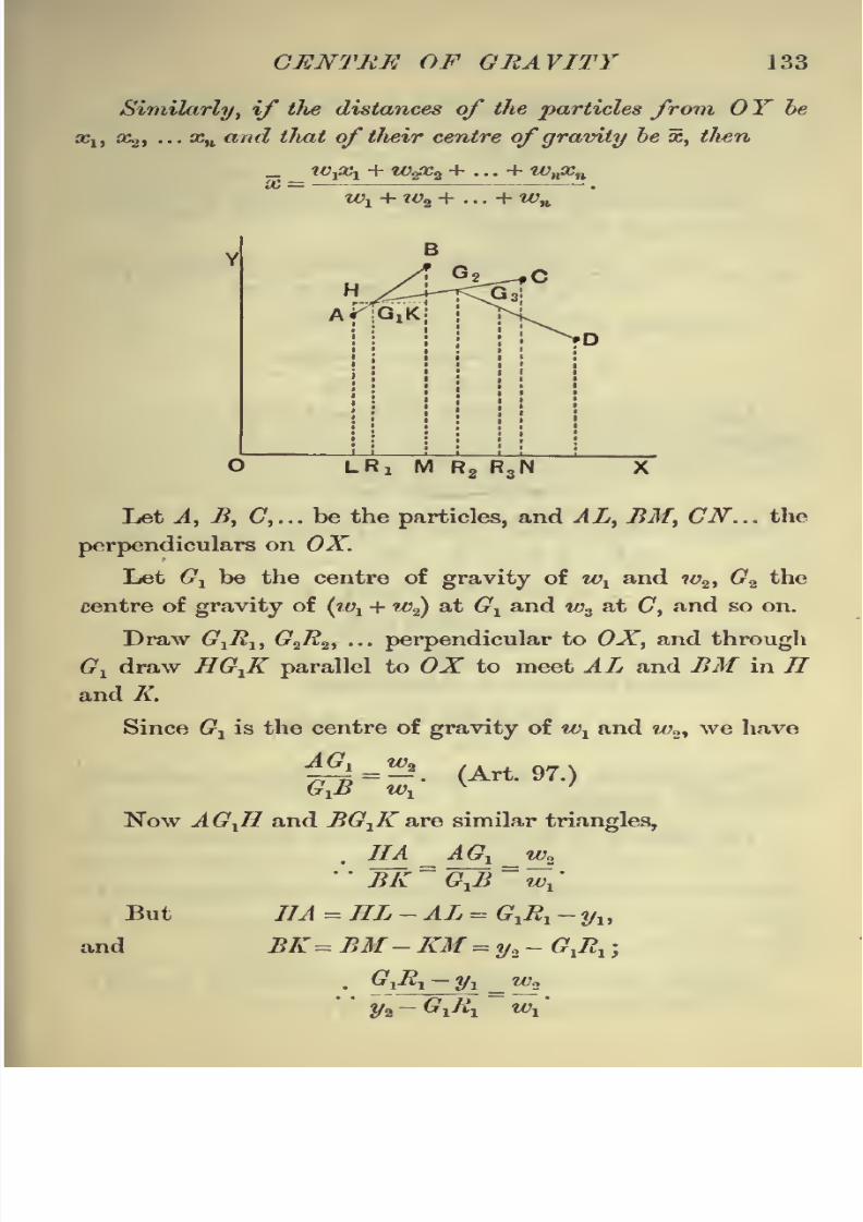
8/13/2019 Elements of Static 00
http://slidepdf.com/reader/full/elements-of-static-00 147/369
CENTRE OF GRAVITY 133
Similarly, if the distances of the particles from OY be
xlt X2, ... xn and tluit of tlieir centre ofgravity be x, tJten
_ tOj&i + w^x2 + ... + wHxn
Let A, B, C,... be the particles, and AL, BM, CN... the
perpendiculars on OX.
Let G1be the centre of gravity of w
xand w2 ,
G2 the
centre of gravity of (ivx + w2)at G
xand w3
at C, and so on.
Draw G1R
l ,G
2R
2 ,... perpendicular to OX, and througli
Gx draw HG
X
K parallel to OX to meet AL and BM in IIand K.
Since G1is the centre of gravity of w
xand w
2ywe have
|=^. (Art. 97.)GXB w
x
x
Now AG-fl and BG^K are similar triangles,
BK
=G~Jt
=w
x
7/J =HL-AL = G& -yu
BK = J?ilf- JOf = ya- tf,tfx
2/a ~ ^1^1 *
'
But
and

8/13/2019 Elements of Static 00
http://slidepdf.com/reader/full/elements-of-static-00 148/369
134 STATICS
Hence wt (G& --yi)
= w2 (y2
- G& ) ;
.-. Q^-^* ** (1).
Similarly, since G2 is the centre of gravity of {wx+ w2)
at Gi and w3at C, we have
T2 2
Wi + w2 + ws w^ + w2 + w3
' ^ v /'
Proceeding in this way we easily obtain
- >1y1
+ tgaya +... +M>ylt
y =.
w1+ w2 + ... + wn
Again, since the triangles AGXH and BG
XK are similar,
we have
GXK~ G
yB ~w
1
'
But iT^ -- XJ?x=
OJ?x- OX = 02^ - *, ,
and G1K=R
lM=OM-OR
1= xi-OR1 .
.'. w1 (OR1
x1)= w
2 (x2 OR1 ).
Hence 0*. =** + **
.
tOj + w2
Proceeding as before we finally have
_ _ WjQCy + w<$c% + . . . + wnxn
wl+ w2 + ... + wn
The theorem of this article may be put somewhat
differently as follows;
The distance of the centre of gravity from any line in
the plane of tJie particles is equal to a fraction, wliose
numerator is the sum of the products of each weight into its
distance from the given line, and whose denominator is tlie
sum of the weights.
In other words, the distance of the centre of gravity is
equal to the average distance of the particles.

8/13/2019 Elements of Static 00
http://slidepdf.com/reader/full/elements-of-static-00 149/369
CENTRE OF GRAVITY 135
112. The formula of the preceding article may be deduced from
Article 93. For, since the resultant weight (w1 + w2+ ...+wn) acting
at G, where G is the centre of gravity of all the weights, is equivalent
to the
component weights
wl ,w
2,... the resultant would, if the line
OX be supposed to be a fixed axis, have the same moment about
this fixed axis that the component weights have.
But the moment of the resultant is
(w1 +w2+...+wn)y,and the sum of the moments of the weights is
Wiyl+w2y2 +... +wr$n .
Hence -w^+w^y^ ... + wnyn=w
Jy1+wiy2+ .
In a similar manner we should have
w1 +wa+...+wn
113. Ex.1. A square lamina, whose loeight is 10 lbs., Jias attached
to its angular points particles lohose weights, taken in order, are 3, 6, 5,
and 1 lbs. respectively. Find the position of the centre of gravity ofthe system, if the side
of
the lamina be 25 inches.
Let the particles be placed at the angular points 0, A, B, and C.
Let the two fixed lines from which the distances are measured be OAand OG.
The weight of the lamina acts at its centre D. Let G be the
required centre of gravity and draw DL and GM perpendicularto OX.
The distances of the points 0, A, B, C, andD from OX are clearly
0, 0, 25, 25, and 12^ inches respectively.
.0 + 5. 25 + 1. 25 + 10. 12^ 275,~ _ 3.0 + 6.MG= y= = =-=11 ins.3 + 6 + 5 + 1 + 10 25
So the distances of the particles from OY are 0, 25, 25, 0, and
12i|inches respectively.
OM=x=3.0 + 6.25 + 5.25 + 1.0 + 10 121 _ 400
3+6+5+1+10
=
w=16ins.

8/13/2019 Elements of Static 00
http://slidepdf.com/reader/full/elements-of-static-00 150/369
|36 STATICS
Hence the required point may be obtained by measuring 16 inches
from O along OA and then erecting a perpendicular of length 11 inches.
Ex. 2. OAB is an isosceles weightless triangle, lohose hase OA is
6 inches and whose sides are each 5 inches; at the points O, A, and Bare placed particles of weights 1, 2, and 3 lbs.; find their centre of
gravity.
Let the fixed line OX coincide with OA and let OF be a perpen-dicular to OA through the point 0.
If BL be drawn perpendicular to OA, then 0L= S ins., and
LB= fJ&^3*= tins.
Hence, if G be the required centre of gravity and GM be drawnperpendicular to OX, we have
0M=1. + 2 6 +3.3^21 ^1+2+3 6
2
. - Tn 1.0 + 2.0 + 3.4 12 -, ,
and MG= - =_ = 2 inches.1+2+3 6
Hence the required point is obtained by measuring a distance
3^ inches from along OA and then erecting a perpendicular of
length 2 inches.
114. Centre of Parallelforces.
The methods and formulae of Arts. 109 and 111 will
apply not only to weights, but also to any system of parallel
forces and will determine the position of the resultant of
any such system. The magnitude of the resultant is the
sum of the forces. Each force must, of course, be taken
with its proper sign prefixed.
There is one case in which we obtain no satisfactory
result;
if the algebraic sum of the forces be zero, the
resultant force is zero, and the formulae of Art. Ill give
x cc,and y=co.
In this case the system of parallel forces is, as in
Art. 53, equivalent to a couple.

8/13/2019 Elements of Static 00
http://slidepdf.com/reader/full/elements-of-static-00 151/369
CENTRE OF GRAVITY 137
EXAMPLES. XVIL
1. Particles of 1, 2, 3, and 4 lbs. weight are placed at the angular
points of a square ;find the distance of their c.o. from the centre of
the square.
2. At two opposite corners A and C of a square ABCD weights
of 2 lbs. each are placed, and at B and D are placed 1 and 7 H>s.
respectively ;find their centre of gravity.
3. Particles of 5, 6, 9, and 7 lbs. respectively are placed at the
corners A, B, C, and t> of a horizontal square, the length of whose side
is 27 inches; find where a single force must be applied to preserve
equilibrium.
4. Five masses of 1, 2, 3, 4, and 5 ounces respectively are placed
on a square table. The distances from one edge of the table are 2, 4,
6, 8, and 10 inches and from the adjacent edge 3, 5, 7, 9, and 11 inches
respectively. Find the distance of the centre of gravity from the two
edges.
5. Weights proportional to 1, 2, and 3 are placed at the corners
of an equilateral triangle, whose side is of length a;find the distance
of their centre of gravity from the first weight.
Find the distance also if the weights be proportional to 11, 13,
and 6.
6. ABC is an equilateral triangle of side 2 feet. At A , B, and Care placed weights proportional to 5, 1, and 3, and at the middle
points of the sides BC, CA, and AB weights proportional to 2, 4,
and 6;shew that their centre of gravity is distant 16 inches from B.
7. Equal masses, each 1 oz., are placed at the angular points of
a heavy triangular lamina, and also at the middle points of its sides;
find the position of the centre of gravity of the masses.
8. ABC is a triangle right-angled at A, AB being 12 and AC15 inches; weights proportional to 2, 3, and 4 respectively are placed
at A, C, and B
;find the distances of their centre of gravity from B
and C.
9. Particles, of mass 4, 1, and 1 lbs., are placed at the angular
points of a triangle ;shew that the centre of gravity of the particles
bisects the distance between the centre of gravity and one of the
vertices of the triangle.
10. Three masses are placed at the angular points of a triangle
ABC. Find their ratios if their centre of inertia be halfway between
A and the middle point of BC.

8/13/2019 Elements of Static 00
http://slidepdf.com/reader/full/elements-of-static-00 152/369
138 STATICS Exs. XVII
11. Bodies of mass 2, 3, and 4 lbs. respectively are placed at the
angular points A,B, and C of a triangle ;find their centre of gravity G,
and shew that forces 2GA, 3GB, and 4GC are in equilibrium.
12. ABC is a uniform triangular plate, of mass 3 lbs. Masses
of 2, 3, and 5 lbs. respectively are placed at A, B, and C. Find the
position of the centre of gravity of the whole system.
13. To the vertices A, B, and C of a uniform triangular plate,
whose mass is 3 lbs. and whose centre of gravity is G, particles of
masses 2 lbs., 2 lbs., and 11 lbs., are attached;shew that the centre
of gravity of the system is the middle point of GC.
14. Masses of 2, 3, 2, 6, 9, and 6 lbs. are placed at the angularcorners of a regular hexagon, taken in order; find their centre of
gravity.
15. Weights proportional to 5, 4, 6, 2, 7, and 3 are placed at the
angular points of a regular hexagon, taken in order ; shew that their
centre of gravity is the centre of the hexagon.
16. Weights proportional to 1, 5, 3, 4, 2, and 6 are placed at the
angular points of a regular hexagon, taken in order;shew that their
centre of gravity is the centre of the hexagon.
17. If weights proportional to the numbers 1, 2, 3, 4, 5, and 6 be
placed at the angular points of a regular hexagon taken in order,
shew that the distance of their centre of gravity from the centre of
the circumscribingcircle of the hexagon is-fths of the radius of the circle.
18.At the
angular pointsof a
square,taken in
order,there act
parallel forces in the ratio 1:3:5:7; find the distance from the
centre of the square of the point at which their resultant acts.
19. A, B, C, and D are the angles of a parallelogram taken in
order ;like parallel forces proportional to 6, 10, 14, and 10 respectively
act at A, B, C, and D;shew that the centre and resultant of these
parallel forces remain the same, if, instead of these forces, parallel
forces, proportional to 8, 12, 16, and 4, act at the points of bisection
of the sides AB, BG, CD, and DA respectively.
20. Find the centre of parallel forces equal respectively to P, 2P,
3P, 4P, 5P, and 6P, the points of application of the forces being at
distances 1, 2, 3, 4, 5, and 6 inches respectively from a given point Ameasured along a given line AB.
21. Three parallel forces, P, Q, and R, act at the verticesA, B, and
C, of a triangle and are proportional respectively to a, b, and c. Find
the magnitude and position of their resultant.

8/13/2019 Elements of Static 00
http://slidepdf.com/reader/full/elements-of-static-00 153/369
CENTRE OF GRAVITY 139
115. Given the centre ofgravity oftlie two portions of a
body, tofind the centre ofgravity of the whole body.
Let the given centres of gravity be Gl and G2 , and let
the weights of the two portions be W1and W.
2 ;the re-
quired point G, by Art. 97, divides GXG
2so that
GXG\GG2 \: W2 : W
x.
The point G may also be obtained by the use of
Art. 109.
Ex. On the same base AB, and on opposite sides of it, isosceles
triangles CAB and DAB are described whose
altitudes are 12 inches and 6 inches respectively.
Find the distance from AB of the centre of
gravity of the quadrilateral CADB.
Let CLD be the perpendicular to AB, meet-
ing it in L, and let G1and G
2be the centres of
gravity of the two triangles CAB and DAB
respectively.Hence
CGx=
-g. CL = &,
and CG2=CL +LG2
=12 + 2 = U.
The weights of the triangles are propor-
tional to their areas, i.e., to \AB . 12 and \AB . 6.
If G be the centre of gravity of the whole figure, we have
A CAB xCGx + ADAB x CG2
aCAB+aDAB
- %AB.12x8 + %AB.6xU _ 48+ 42 _ 90 _
$AB.12 + $AB.6
6+ 3~
9
Hence LG= CL-CG= 2 inches.
This result may be verified experimentally by cutting the figure
out of thin cardboard.
116. Given the centre of gravity of the whole of a body
and of a portion of the body, to find the centre of gravity of
the remainder.
Let G be the centre of gravity of a body ABCD, and G1
that of the portion ADC.
Let W be the weight of the whole body and Wxthat of
the portion ACD, so that Wa (= W- Wx)
is the weight of
the portion ABC.

8/13/2019 Elements of Static 00
http://slidepdf.com/reader/full/elements-of-static-00 154/369
140 STA TICS
Let G2be the centre of gravity of the portion ABC.
Since the two portions of the body make up the whole,
therefore W1 at G
x and W2 at G2 must have their centre
of
gravity at G.
Hence G must lie on G-fi2and be such that
Wx'.QQx**. W2.GG2 .
Hence, given G and G1}we obtain G2 by producing GXQ
to G2 , so thatW
6'^.ir- WY
The required point may be also obtained by means of
Art. 109.
Ex. 1. From a circular disc, of radius r, is cut out a circle, whose
diameter is a radius of the disc; find the centre of gravity of the
remainder.
Since the areas of circles are to one another as the squares of their
radii,
,*. area of the portion cut out
: area of the whole circle
::1 :4.
Hence the portion cut off is one-
quarter, and the portion remaining is
three-quarters, of the whole, so that

8/13/2019 Elements of Static 00
http://slidepdf.com/reader/full/elements-of-static-00 155/369
CENTRE OF GRAVITY 141
Now the portions W1and W
2make up the whole disc, and therefore
balance about 0.
Hence W2
. OG2=W
l.
OG^W,x Jr.
.-. OG2=\r.
This may be verified experimentally.
Ex. 2. .From a triangular laminaABC is cut off, by a line parallel
to its base BC, onc-qwirter of its area; find the centre of gravity of the
remainder.
Let AB1C
1be the portion cut off, 4
so that,./
aAB^ : a ABC :: 1 : 4. ..-'/''
By Geometry, since the triangles Bx ..-'''
/IAB
1G
land yli>C are similar, we have S
-fz
AABXC
X: aABC::AB?\AW. yS /Q
l
.: AB* : AB* :: 1 : 4,Q^ /Q
and hence yfBj= ^i?. D
The line Bi C\ therefore bisects AB, AC, and AD.
Let G and G, be the centres of gravity of the triangles ABC andAB
1C
1 respectively ;also let W
tand W
2 be the respective weights of
the portion cut off and the portion remaining, so that W.y SWj.
Since Wo at G2and W
1at G
xbalance about G, we have, by Art. 109,
_ Wi -P^i + TF2 . DG
U _DG1 + 3DGa
^x+W^a 4 W *
But DG =$DA = DDlt
and
DG^D^+
^D^=DDj^DD^DD^Hence
(i)is 4 x fDI^ =$DDX + 3DG2
.
This result can also be easily verified experimentally.
EXAMPLES. XVIII.
{The student should verify some of the following questions experi-
mentally ; suitable ones for this purpose are Nos. 1, 2, 4, 5, 8, 9, 10,
11, 17, 18, and 19.]
1. A uniform rod, 1 foot in length, is broken into two parts, of
lengths 5 and 7 inches, which are placed so as to form the letter T> t>ne
longer portion being vertical ;find the centre of gravity of the system.
2. Two rectangular pieces of the same cardboard, of lengths 6 and
8 inches and breadths 2 and 2^ inches respectively, are placed touching,
but not overlapping, one another on a table so as to form a T-shaped
figure, the longer portion being vertical. Find the position of its centre
of gravity.

8/13/2019 Elements of Static 00
http://slidepdf.com/reader/full/elements-of-static-00 156/369
142 STATICS Exs.
3. A heavy beam consists of two portions, whose lengths are as
3:5, and who3e weights are as 3 : 1; find the position of its centre
of gravity.
4. Two sides of a rectangle are double of the other two, and on
one of the longer sides an equilateral triangle is described ; find
the centre of gravity of the lamina made up of the rectangle and
the triangle.
5. A piece of cardboard is in the shape of a square ABCD with
an isosceles triangle described on the side BC; if the side of the
square be 12 inches and the height of the triangle be 6 inches, find the
distance of the centre of gravity of the cardboard from the line AD.
6. An isosceles right-angled triangle has squares described ex-
ternally on all its sides. Shew that the centre of gravity of the figure
so formed is on the line, which bisects the hypothenuse and passes
through the right angle, and divides it in the ratio 1 : 26.
7. Two uniform spheres, composed of the same materials, and
whose diameters are 6 and 12 inches respectively, are firmly united ;
find the position of their centre of gravity.
8. From a parallelogram is cut one of the four portions into
which it is divided by its diagonals ;find the centre of gravity of the
remainder.
9. A parallelogram is divided into four parts, by joining the
middle points of opposite sides, and one part is cut away; find the
centre of gravity of the remainder.
10. From a square a triangular portion is cut off, by cutting the
square along a line joining the middle points of two adjacent sides;
find the centre of gravity of the remainder.
11. From a triangle is cut off ^th of its area by a straight line
parallel to its base. Find the position of the centre of gravity of the
remainder.
12. ABC is an equilateral triangle, of 6 inches side, of which
is the centre of gravity. If the triangle OBC be removed, find the
centre of gravity of the remainder.
13. If from a triangle ABC three equal triangles ARQ, BPR,and CQP, be cut off, shew that the centres of inertia of the triangles
ABC and PQB are coincident.
14. G is the centre of gravity of a gives, isosceles triangle, right-
angled at A, and having BC equal to a. The portion GBC is cut
away; find the distance of the centre of gravity of the remainder
from A.

8/13/2019 Elements of Static 00
http://slidepdf.com/reader/full/elements-of-static-00 157/369
XVIII CENTRE OF GRAVITY 143
15. On the same base BG are two triangles, ABC and A'BC, the
vertex A' falling within the former triangle. Find the position of A'
when it is the centre of gravity of the area between the two triangles.
16. Two triangles, each th of the whole, are cut off from a
given triangle at two of its angular points, B and C, by straight lines
parallel to the opposite sides; find the c.g. of remainder.
17. Out of a square plate shew how to cut a triangle, having one
side of the square for base, so that the remainder may have its centre
of gravity at the vertex of this triangle and therefore rest in anyposition if this point be supported.
y 18. A uniform plate of metal, 10 inches square, has a hole of area
3 square inches cut out of it, the centre of the hole being 2^- inches
from the centre of the plate ; find the position of the centre of gravityof the remainder of the plate.
j, 19. Where must a circular hole, of 1 foot radius, be punched cutof a circular disc, of 3 feet radius, so that the centre of gravity of
the remainder may be 2 inches from the centre of the disc?
20. Two spheres, of radii a and b, touch internally; find the
centre of gravity of the solid included between them.
21. If a right cone be cut by a plane bisecting its axis at right
angles, find the distance of the vertex of the cone from the centre of
gravity of the frustum thus cut off.
22. A solid right circular cone of homogeneous iron, of height64 inches and mass 8192 lbs.
,is cut by a plane perpendicular to its
axis so that the mass of the small cone removed is 686 lbs. Find the
height of the centre of gravity of the truncated portion above the base
of the cone.
23. A solid right circular cone has its base scooped out, so thatthe hollow is a right cone on the same- base; how much must be
scooped out so that the centre of gravity of the remainder may coincide
with the vertex of the hollow?
24. The mass of the moon is '013 times that of the earth.
Taking the earth's radiumsas 4000 miles and the distance of the moon's
centre from the earth's centre as 60 times the earth's radius, find the
distance of the c.g. of the earth and moon from the centre of the earth.

8/13/2019 Elements of Static 00
http://slidepdf.com/reader/full/elements-of-static-00 158/369
144 STATICS
117. Centre of gravity of a hemisphere.
If a hemisphere be of radius r, the centre of gravity-
lies on that radius which is perpendicular to its plane
2>r
face, and is at a distance-5-
from the centre of the planeo
rface. If the hemisphere be hollow, the distance is .
The proofs of these statements are difficult by elementary
methods; they will be found in the last chapter.
118. To find the centre of gravity of a quadrilateral
lamina having two parallel sides.
Let ABCD be the quadrilateral, having the sides AB
and CD parallel and equal to 2a and 2b respectively.
D F c
Let E and F be the middle points of AB and CD
respectively.Join DE and EC
;the areas of the triangles
ADE, DEC, and BEC are proportional to their bases
AE, DC, and EB, i.e., are proportional to a, 26, and a.
Replace them by particles equal to one-third of their
weight placed at their angular points (Art. 104).
We thus have weights proportional to
k + ^- at each of C and D,.5 o
k at each of A and B,o
2a 2b Land -K- +
-qat E.

8/13/2019 Elements of Static 00
http://slidepdf.com/reader/full/elements-of-static-00 159/369
CENTRE OF GRAVITY 145
Again, replace the equal weights at and D by a
weight proportional
to-%-
+ -=- at the middle point Fo o
of (72), and the equal weights at A and B by a weight
proportional to-5-
at E.
We thus have weights
y + T at^
and -- + -5-at JL.
Hence the required centre of gravity G is on the
straight line EF, and is such that
EG _ weight at F _ a + 26
^~weight at E
~2a + b
'
EXAMPLES. XIX.
1. A triangular table rests on supports at its vertices; weights of
6, 8, and 10 lbs. are placed at the middle points of the sides. Find byhow much the pressures on the legs are increased thereby.
2. A piece of thin uniform wire is bent into the form of a four-
sided figure, ABCD, of which the sides AB and CD are parallel, and
BG and DA are equally inclined to AB. If AB be 18 inches, CD12 inches, and BC and DA each 5 inches, find the distance from ABof the centre of gravity of the wire.
3. AB, BC and CD are three equal uniform rods firmly joined,
so as to form three successive sides of a regular hexagon, and are
suspended from the point A;shew that CD is horizontal.
4. ABC is a piece of uniform wire;
its two parts AB and BG are
straight, and the angle ABC is 135. It is suspended from a fixed
point by a string attached to the wire at B, and the part AB is
observed to be horizontal. Shew that BG is to AB as J/2 to 1.
5. A rod, of length 5a, is bent so as to form five sides of a regular
hexagon ; shew that the distance of its centre of gravity from either
end of the rod is
_n
^133.
L. S. 10

8/13/2019 Elements of Static 00
http://slidepdf.com/reader/full/elements-of-static-00 160/369
146 STATICS Exs.
6. The side CD of a uniform trapezoidal lamina ABCD is twice
as long as AB, to which it is opposite and parallel; compare the
distances of the centre of gravity of ABCD from AB and CD.
7. If the centre of gravity of a quadrilateral lamina ABCDcoincide with one of the angles A, shew that the distances of A and Cfrom the line BD are as 1 : 2.
8. A uniform quadrilateral ABCD has the sides AB and AD, and
the diagonal AC all equal, and the angles BAC and CAD are 30 and
60 respectively. If a weight, equal to two-thirds that of the triangle
ABC, be attached at the point B, and the whole rest suspended from
the point A, shew that the diagonal AC will be vertical.
9. Explain what will take place when 3 forces, represented byAB, BC, and CA respectively, act along the sides of a triangular board
ABC which is supported on a smooth peg passing through its centre
of gravity.
10. Three forces act at a point O in the plane of a triangle ABC,being represented by OA, OB and OC; where must be the point O so
that the three forces may be in equilibrium ?
U. A particle P is attracted to three points A, B, C by forces
equal to ix . PA, /j.. PB, and fi
. PC respectively; shew that the re-
sultant is3/jl . PG, where G is the centre of gravity of the triangle
ABC.
12. A particle P is acted upon by forces towards the points
A, B, C, ... which are represented by X . PA, ft . PB, v . PC, ... ;shew
that their resultant is represented by (\+/jl+ v + ...)PG, where G is
the centre ofgravity
ofweights placed
at
A, B, C,...
proportionalto X, ft, v, ... respectively.
[This is the generalised form of Art. 42, and may be proved bysuccessive applications of that article.]
13. A uniform rod is hung up by two strings attached to its ends,
the other ends of the strings being attached to a fixed point; shewthat the tensions of the strings are proportional to their lengths.
Prove that the same relation holds for a uniform triangular lamina
hung up by three strings attached to its angular points.
14. Find the vertical angle of a cone in order that the centre of
gravity of its whole surface, including its plane base, may coincide
with the centre of gravity of its volume.
15. A cylinder and a cone have their bases joined together, the
bases being of the same size ;find the ratio of the height of the cone
to the height of the cylinder so that the common centre of gravity maybe at the centre of the common base.

8/13/2019 Elements of Static 00
http://slidepdf.com/reader/full/elements-of-static-00 161/369
XIX CENTRE OF GRAVITY 147
16. Shew how to cut out of a uniform cylinder a cone, whose base
coincides with that of the cylinder, so that the centre of gravity of the
remaining solid may coincide with the vertex of the cone.
17. If the diameter of the base of a cone be to its altitude as
1 : ,/2, shew that, when the greatest possible sphere has been cut
out, the centre of gravity of the remainder coincides with that of the
cone.
18. From a uniform right cone, whose vertical angle is 60, is cut
out the greatest possible sphere; shew that the centre of gravity of
the remainder divides the axis in the ratio 11 : 49.
19. A solid in the form of a right circular cone has its base
scooped out, so that the hollow so formed is a right circular cone onthe same base and of half the height of the original cone ; find the
position of the centre of gravity of the cone so formed.
20. A uniform equilateral triangle ABC is supported with the
angle A in contact with a smooth wall by means of a string BD, equalin length to a side of the triangle, which is fastened to a point D ver-
tically above A. Shew that the distances of B and C from the wall
are as 1 : 5.
21. A cone, whose height is equal to four times the radius of its
base, is hung from a point in the circumference of its base;shew that
it will rest with its base and axis equally inclined to the vertical.
22. Two right cones, consisting of the same material, have equalslant slides and vertical angles of 60 and 120 respectively, and are
so joined that they have a slant side coincident. Shew that, if theybe suspended from their common vertex, the line of contact will beinclined at 15 to the vertical.
23. A triangular piece of paper is folded across the line bisectingtwo sides, the vertex being thus brought to lie on the base of the
triangle. Shew that the distance of the centre of inertia of the paperin this position from the base of the triangle is three-quarters that of
the centre of inertia of the unfolded paper from the same line.
24. A rectangular sheet of stiff paper, whose length is to its
breadth as ^/2 to 1, lies on a horizontal table with its longer sides
perpendicular to the edge and projecting over it. The corners on the
table are then doubled over symmetrically, so that the creases pass
through the middle point of the side joining the corners and makeangles of 45 with it. The paper is now on the point of falling over;
shew that it had originally f-f-ths of its length on the table.
25. At each of n - 1 of the angular points of a regular polygon of
n sides a particle is placed, the particles being equal; shew that the
distance of their centre of gravity from the centre of the circle
circumscribing the polygon is^
where r is the radius of the
circle.
102

8/13/2019 Elements of Static 00
http://slidepdf.com/reader/full/elements-of-static-00 162/369
148 STATICS Exs. XIX
26. A square hole is punched out of a circular lamina, the
diagonal of the square being a radius of the circle. Shew that the
centre of gravity of the remainder is at a distance - from the
centre of the circle, where a is the diameter of the circle.
27. From a uniform triangular board a portion consisting of the
area of the inscribed circle is removed;shew that the distance of the
centre of gravity of the remainder from any side, a, is
S 2s*-3waS
3as s*-irS'
where S is the area and s thesemiperimeter
of the board.
28. A circular hole of a given size is punched out of a uniform cir-
cular plate ;shew that the centre of gravity lies within a certain circle.
29. The distances of the angular points and intersection of the
diagonals of a plane quadrilateral lamina from any line in its plane
are a, b, c, d, and e; shew tliat the distance of the centre of inertia
from the same line is ^ (a + b+ c + d-e).
Let A, B, C, D be the angular points, and E the intersection of the
diagonals. Then
AACD _ perpendicular from D on AG _DE _d-eAAGB
~perpendicular from B on AG
~EB
~~
e - b'
By Arts. 104 and 111 the distance of the centre of gravity of the
AACD from OX isa + c + d
and that of the aACBisa+ c + b
.
6 o
Hence distance of required c.g. from OX
_ AACDx^(a+c+d)+ aACBx^ (a+ b+ c)
AACD+AACB
_ (d-e)(a+ c+ d) + (e-b)(a+b+c)_F
(d-e) + (e-b)
= ^(a+b+ c+d-e), on reduction.
30. If A and B be the positions of two masses, m and n, and if
G be their centre of gravity, shew that, if P be any point, then
m . AP*+ n . BP2=m . AG*+n . BG9+(m+n) PG\
Similarly, if there be any number of masses, m,n,p,... at points
A, B, G, ... ,and G be their centre of gravity, shew that
m . APt+n . BP*+p . CF^+ ...
=m . AG*+n . BG*+p . CGf2+ ... + (m+n+p+ ...)PGK

8/13/2019 Elements of Static 00
http://slidepdf.com/reader/full/elements-of-static-00 163/369
CHAPTER X.
CENTRE OF GRAVITY {continued).
119. If a rigid body be in equilibrium, one point
only of the body being fixed, the centre of gravity of (lie body
will be in tlie vertical line passing through the fixed point of
(lie body.
Let be the fixed point of the body, and G its centre of
gravity.
The forces acting on the body are the reaction at
the fixed point of support of the body, and the weights of
the component parts of the body.
The weights of these component parts are equivalent to
a single vertical force through the centre of gravity of the
body.

8/13/2019 Elements of Static 00
http://slidepdf.com/reader/full/elements-of-static-00 164/369
150 STATICS
Also, when two forces keep a body in equilibrium, they
must be equal and opposite and have the same line of action.
Butthe lines of
action cannot be the same unless thevertical
line through G passes through the point 0.
Two cases arise;the first, in which the centre of gravity
G is below the point of suspension 0, and the second, in
which G is above 0.
In the first case, the body, if slightly displaced from its
position of equilibrium, will tend to return to this position;
in the second case, the body will not tend to return to its
position of equilibrium.
120. To find, by experiment, the centre of gravity of
a body of any shape.
Take a flat piece of cardboard of any shape. Bore
several small holes A, B,C,D,... in it
of a size just large enough to freely
admit of the insertion of a small pin.
Hang up the cardboard by the
hole A and allow it to hang freely
and come to rest. Mark on the card-
lx>ard the line AA '
which is now
vertical. This may be done by hang-
ing from the pin a fine piece of string
with a small plummet of lead at the other end, the string
having first been well rubbed with chalk. If the string be
now flipped against the cardboard it will leave a chalked
line, which is AA'. Now hang up the cardboard with the
hole B on the pin, and mark in a similar manner the line
BB' which is now vertical.
Perform the experiment again with the points C, D, Eas the points through which the small pin passes, and
obtain the corresponding vertical lines
CG\DD', EE'.

8/13/2019 Elements of Static 00
http://slidepdf.com/reader/full/elements-of-static-00 165/369
CENTRE OF GRAVITY 151
These chalked lines AA', BB', CG', DD', EE' will all be
found to pass through the same point G. If the thickness
of the cardboard be neglected,this
point Gis its centre of
gravity.If the pin be now passed through G, the card-
board will be found to rest in any positionin which it is
placed.
121. If a body be placed with its base in contact with
a horizontal plane, it will stand, or fall, according as the
vertical line drawn through the centre of gravity of the body
meets the plane within, or without, the base.
The forces acting on the body are its weight, which acts
at its centre of gravity G, and the reactions of the plane,
acting at different points of the base of the body. These
reactions are all vertical, and hence they may be com-
pounded into a single vertical force acting at some point
of the base.
Since the resultant of two like parallel forces acts
alwaysat a
pointbetween the
forces,
it follows that the
resultant of all the reactions on the base of the body
cannot act through a point outside the base.
Hence, if the vertical line through the centre of gravity
of the body meet the plane at a point outside the base,
it cannot be balanced by the resultant reaction, and the
body cannot therefore be in equilibrium,but must fall over.

8/13/2019 Elements of Static 00
http://slidepdf.com/reader/full/elements-of-static-00 166/369
152 STATICS
If the base of the body be a figure having a re-entrant
D
angle, as in the above figure,we must extend the meaning
of the word base in the enunciation to mean the area
included in the figure obtained by drawing a piece of thread
tightly round the geometrical base. In the above figure
the base therefore means the area ABDEFA.
For example, the point G, at which the resultant
reaction acts, may lie within the area AHB, but it cannot
lie without the dotted line AB.
If the point G were on the line AB, between A and B,
the body would be on the point of falling over.
Ex. A cylinder, of height h, and the radius of whose base is r, is
placed on an inclined, plane and prevented
from sliding; if the inclination of the
plane be gradually increased, find when
the cylinder will topple.
Let the figure represent the section
of the cylinder when it is on the point of
toppling over; the vertical line through
the centre of gravity G of the body must
thereforejust pass
through the end A of
the base. Hence GAD must be equal to
the angle of inclination, a, of the plane.
Hence -=-J1
=tan<7^B=cota;
2r. . tan a= -=-
h
giving the required inclination of the plane.

8/13/2019 Elements of Static 00
http://slidepdf.com/reader/full/elements-of-static-00 167/369
CENTRE OF GRAVITY 153
Stable, unstable, and neutral equilibrium.
122. We have pointed out in Art. 119 that the body
in the first figure of that article would, if slightly dis-
placed, tend to return to its position of equilibrium, and
that the body in the second figure would not tend to return
to its original position of equilibrium, but would recede
still further from that position.
These two bodies are said to be in stable and unstable
equilibrium respectively.
Again, a cone, resting with its flat circular base in
contact with a horizontal plane, would, if slightly displaced,
return to its position of equilibrium ;if resting with its
vertex in contact with the plane it would, if slightly dis-
placed, recede still further from its position of equilibrium;
whilst, if placed with its slant side in contact with the
plane, it will remain in equilibrium in any position. The
equilibrium in the latter case is said to be neutral.
123. Consider, again, the case of a heavy sphere,
resting on a horizontal plane, whose centre of gravity is
not at itscentre.
Let the first figure represent the position of equilibrium,
the centre of gravity being either below the centre 0, as Glt
or above, as G2 . Let the second figure represent the sphere
turned through a small angle, so that B is now the point of
contact with the plane.

8/13/2019 Elements of Static 00
http://slidepdf.com/reader/full/elements-of-static-00 168/369
154 STATICS
The reaction of the plane still acts through the centre
of the sphere.
If the weight of the body act through Gu it is clear that
the body will return towards its original position of equi-
librium, and therefore the body was originally in stable
equilibrium.
If the weight act through G2 ,the body will move still
further from its original position of equilibrium, and there-
fore it was originally in unstable equilibrium.
If however the centre of gravity of the body had been
at 0, then, in the case of the second figure, the weight
would still be balanced by the reaction of the plane ;the
body would thus remain in the new position, and the
equilibriumwould be called neutral.
124. Def. A body is said to be in stable equi-
librium when, if it be slightly displaced from its position
of equilibrium, the forces acting on the body tend to
make it return towards its position of equilibrium ;it is
in unstable equilibrium when, if it be slightly displaced,
the forces tend to move it still further from its position of
equilibrium ;it is in neutral equilibrium, if the forces
acting on it in its displaced position are in equilibrium.
In general bodies which are top-heavy, or which have
small bases, are unstable.
Thus in theory a pin might be placed upright with its
point
on a horizontal table so as to be in equilibrium ;in
practice the base would be so small that the slightest
displacement would bring the vertical through its centre of
gravity outside its base and it would fall. So with a billiard
cue placed vertically with its end on the table.
A body is,as a general principle,
in a stable position of
equilibrium
when the centre of gravity is in the lowest

8/13/2019 Elements of Static 00
http://slidepdf.com/reader/full/elements-of-static-00 169/369
CENTRE OF GRAVITY 155
position it can take up ; examples are the case of the last
article, and the pendulum of a clock;the latter when dis-
placed always returns towards its position of rest.
Consider again the case of a man walking on a tight
rope. He always carries a pole heavily weighted at one
end, so that the centre of gravity of himself and the pole is
always below his feet. When he feels himself falling in one
direction, he shifts his pole so that this centre of gravity
shall he on the other side of his feet, and then the resultant
weight pulls him back again towards the upright position.
If a body has more than one theoretical position of
equilibrium, the one in which its centre of gravity is lowest
will in general be the stable position, and that in which the
centre of gravity is highest will be the unstable one.
125. Ex. A homogeneous body, consisting of a cylinder anda hemisphere joined at their bases, is placed with the hemisplierical end
on a horizontal table; is the equilibrium stable or unstable?
Let Gj and G2be the centres of gravity of the hemisphere and
cylinder, and let A be the point of the bodywhich is initially in contact with the table,
and let be the centre of the base of the
^^o
hemisphere. #^'**^*T*,**^If h be the height of the cylinder, and / / *7
r be the radius of the base, we have IIIOG^fr, and OG
2=% (Art. 117). Ill
Also the weights of the hemisphere and Iq/1 ~~~j
cylinder are proportional to irr3 and it . r2h. \ *
/
I
yThe reaction of the plane, in the dis- ^^ : -^placed position of the body, always passes
through the centre O.
The equilibrium is stable or unstable according as G, the centre
of gravity of the compound body, is below or above O,
i.e., according as
0GX
x wt. of
hemisphere is^OG
2
x wt. ofcylinder,

8/13/2019 Elements of Static 00
http://slidepdf.com/reader/full/elements-of-static-00 170/369
156 STATICS
i.e., according as
i.e., according as
i.e., according as
i.e.,
frxf7rr3 is< -X7rr%
Vris
>h\
r\s<s/2h,
>h x 1-42.
**126. Within the limits of this book we cannot
enter into the general discussion of the equilibrium of one
body resting on another;in the following article we shall
discuss the case in which the portions of the two bodies
in contact are spherical.
A body rests in equilibrium upon another fixed body,
the portions of the two bodies in contact being spheres of
radii r and R respectively ; if the first body be slightly
displaced, to find whether the equilibrium is stable or un-
stable, the bodies being rough enough to prevent sliding.
Let be the centre of the spherical surface of the
lower body, and1
that of
the
upperbody; since there
is equilibrium, the centre of
gravity Gxof the upper body
must be in the line 001}which
passes through the point of
contact A-l of the bodies.
Let
A&be h.
Let the upper body be
slightly displaced, by rolling,
so that the new position of
the centre of the upper body
is 0.z ,
the new point of contact
is
A2 , the new positionof the

8/13/2019 Elements of Static 00
http://slidepdf.com/reader/full/elements-of-static-00 171/369
CENTRE OF GRAVITY 157
centre of gravity is G2 ,and the new position of the point
Axis C. Hence CG2 is h.
Through A2 draw A 2L vertically to meet 2C in L,
and draw2M vertically downwards to meet a horizontal
line through A2 in M.
Let the angle A 2OA 1be 6, and let A
2 2C be<f>,
so that
the angle G02M is(0+
<f>).
Since the upper body has rolled into its new position,
the arc AXA2
is equal to the arc CA2 .
Hence (EleTnents of Trigonometry, Art. 158) we have
R.0 =r.<t> (1),
where r and R are respectively the radii of the upper and
lower surfaces.
The equilibrium is stable, or unstable, according as G2
lies to the left, or right, of the line A2L,
i.e., according as the distance of G2 from 2M is
> or < the distance of L from 2M, i.e., A 2M,
i.e., according as
2G2 sin (0 + <j>)
is > or < O^A? sin 6,
i.e., according as
(r h) sin(0 + <f>)
is > or < r sin 0,
i.e., according as
r h. sin 6is > or <
But
sin (9 + <f>)'
sintf 6
sin(0 + <) e+<f>'
since 6 and < are both very small,
r=
r~+H
,hy'
e(luation
( )

8/13/2019 Elements of Static 00
http://slidepdf.com/reader/full/elements-of-static-00 172/369
l.r>8 STATICS
Hence the equilibrium is stable, or unstable, according as
r h . r
is > or < = ,
r r + Rr2
i.e., according as r -~ is > or < h,r + R '
i.e., according as
i.e., according as
Rr
r + Ris > or < h,
1 . 11T is > or < - + -=
.
h r R
111If r = - + -5 ,
the equilibrium is sometimes said to be
neutral;
it is howeverreally
unstable, but theinvestiga-
tion is beyond the limits of this book.
Hence the equilibrium is stable only when
1 1 1
VS>r+R'
in all other cases it is unstable.
Cor. 1. If the surface of the lower body, instead of
being convex, as in the above
figure, be concave, as in the follow-
ing figure, the above investigation
will still apply provided we change
the sign of R.
Hence the equilibrium is stable
when
1 . 11VS>
r~R'
otherwise itis,
in genera], un-
stable.

8/13/2019 Elements of Static 00
http://slidepdf.com/reader/full/elements-of-static-00 173/369
CENTRE OF GRAVITY 159
Cor. 2. If the upper body have a plane face in
contact with the lower body, as in the following figure, r
is now infinite in value, and therefore - is zero.
if
Hence the equilibrium is stable
l]ie>
R>
i.e.,
h be < R.
Hence the equilibrium is stable,
if the distance of the centre of
gravity of the upper body from its
plane face be less than the radius of the lower body;
otherwise the equilibrium is unstable.
Cor. 3. If the lower body be a plane, so that R is
infinity,the equilibrium is stable if
1 1
T be > -, i.e., if h be < r.
h r
Hence, if a body of sphericalbase be placed on a hori-
zontal table, it is in stable equilibrium, if the distance of
its centre of gravity from the point of contact be less than
the radius of the spherical surface.
EXAMPLES. XX.
1. A carpenter's rule, 2 feet in length, is bent into two parts at
right angles to one another, the length of the shorter portion being8 inches. If the shorter be placed on a smooth horizontal table, whatis the length of the least portion on the table that there may be equi-
librium ?
2. A piece of metal, 18 cubic inches in volume, is made into a
cylinder which rests with its base on an inclined plane, of 30 slope,
and is prevented from slipping. How tall may the cylinder be madeso that it may just not topple over?
3. If a triangular lamina ABC can just rest in a vertical planewith its edge AB in contact with a smooth table, prove that
B&^ACP^SAB2.

8/13/2019 Elements of Static 00
http://slidepdf.com/reader/full/elements-of-static-00 174/369
160 STATICS Exs.
4. The side CD of a uniform square plate ABCD, whose weightis W, is bisected at E and the triangle AED is cut off. The plate
ABCEA is placed in a vertical position with the side CE on a hori-
zontal plane. Whatis
the greatest weightthat can be
placedat A.
without upsetting the plate?
5. ABC is a flat board, A being a right angle and AG in contact
with a flat table; D is the middle point of AC and the triangle ABDis cut away; shew that the triangle is just on the point of falling
6. A brick is laid with one-quarter of its length projecting over
theedge
of a wall;
a brick andone-quarter
of a brick are then laid
on the first with one-quarter of a brick projecting over the edge of the
first brick;a brick, and a half are laid on this, and so on
;shew that
4 courses of brick laid in the above manner will be in equilibrium
without the aid of mortar, but that, if a fifth course be added, the
structure will topple.
7. How many coins, of the same size and having their thick-
nesses equal to -o^li of their diameters, can stand in a cylindrical pile
on an inclined plane, whose height is one-sixth of the base, assumingthat there is no slipping?
If the edge of each coin overlap on one side that of the coin below,
find by what fraction of the diameter each must overlap so that a
pile of unlimited height may stand on the plane.
8. A number of bricks, each 9 inches long, 4 inches wide, and
3 inches thick, are placed one on another so that, whilst their narrowest
surfaces, or thicknesses, are in the same vertical plane*, each brick
overlaps the one underneath it by half an inch; the lowest brick
being placed on a table, how many bricks can be so placed without
their falling over?
9. ABC is an isosceles triangle, of weight W, of which the angle
A is 120, and the side AB rests on a smooth horizontal table, the
Wplane of the triangle being vertical
;if a weight be hung on at C,
shew that the triangle will just be on the point of toppling over.
10. The quadrilateral lamina ABCD is formed of two uniform
isosceles triangles ABC and ADC, whose vertices are B and D, on
opposite sides of a common base AC, the angle ABC being a right
angle. Shew that it will rest in a vertical plane with BC on a hori-
zontal plane, provided the area of ADC be not greater than four times
that of ABC.

8/13/2019 Elements of Static 00
http://slidepdf.com/reader/full/elements-of-static-00 175/369
XX CENTRE OF GRAVITY 161
11. A body, consisting of a cone and a hemisphere on the same
base, rests on a rough horizontal table, the hemisphere being in con-
tact with the table ;find the greatest height of the cone so that the
equilibrium may be stable.
12. A solid consists of a cylinder and a hemisphere of equal
radius, fixed base to base;find the ratio of the height to the radius of
the cylinder, so that the equilibrium may be neutral when the spherical
surface rests on a horizontal plane.
13. A hemisphere rests in equilibrium on a sphere of equal radius;
shew that the equilibrium is unstable when the curved, and stable
when the flat, surface of the hemisphere rests on the sphere.
14. A heavy right cone rests with its base on a fixed rough sphere
of given radius ;find the greatest height of the cone if it be in stable
equilibrium.
15. A uniform beam, of thickness 2b, rests symmetrically on a
perfectly rough horizontal cylinder of radius a;shew that the equi-
librium of the beam will be stable or unstable according as b is less or
greater than a.
16. A heavy uniform cube balances on the highest point of a
sphere, whose radius is r. If the sphere be rough enough to preventirT
sliding, and if the side of the cube be-g- ,
shew that the cube can rock
through a right angle without falling.
17.A lamina in the form of an isosceles triangle, whose vertical
angle is o, is placed on a sphere, of radius r, so that its plane is vertical
and one of its equal sides is in contact with the sphere; shew that, if
the triangle be slightly displaced in its own plane, the equilibrium is
Srstable if sin a be less than , where a is one of the equal sides of the
a
triangle.
18. A weight W is supported on a smooth inclined plane by a
given weight P, connected with W by means of a string passing rounda fixed pulley whose position is given. Find the position of Won the plane, and determine whether the position is stable or un-
stable.
19. A rough uniform circular disc, of radius r and weight p, is
movable about a point distant c from its centre. A string, rough
enough to prevent any slipping, hangs over the circumference and
carries unequal weights W and w at its ends. Find the position of
equilibrium, and determine whether it is stable or unstable.
L. S. 11

8/13/2019 Elements of Static 00
http://slidepdf.com/reader/full/elements-of-static-00 176/369
162 STATICS Exs. XX
20. -A. solid sphere rests inside a fixed rough hemispherical bowl
of twice its radius. Shew that, however large a weight is attached to
the highest point of the sphere, the equilibrium is stable.
21. A thin hemispherical bowl, of radius b and weight W, rests
in equilibrium on the highest point of a fixed sphere, of radius a,
which is rough enough to prevent any sliding. Inside the bowl is
placed a small smooth sphere of weight ic. Shew that the equilibriumis not stable unless
,<JT._.

8/13/2019 Elements of Static 00
http://slidepdf.com/reader/full/elements-of-static-00 177/369
CHAPTER XL
WORK.
127. Work. Def. A force is said to do work
when its point of application moves in the direction of the
force.
The force exerted by a horse, in dragging a waggon, does work.
The force exerted by a man, in raising a weight, does work.
The pressure of the steam, in moving the piston of an engine,
does work.
When a man winds up a watch or a clock he does work.
The measure of the work done by a force is the product
of the force and the distancethrough
which it moves its
point of application in the direction of the force.
Suppose that a force acting at a point A of a body
A B
moves the point A to D, then the work done by P is
measured by the product of P and AD.
If the point D be on the side of A toward which the
force acts, this work is positive; if D lie on the opposite
side, the work is negative.
Next, suppose that the point of application of the force
is moved to a point C, which does not lie on the line AB.
112

8/13/2019 Elements of Static 00
http://slidepdf.com/reader/full/elements-of-static-00 178/369
164 STATICS
Draw CD perpendicular to AB, or AB produced. Then
AD is the distance through which the point of application
is moved in the direction of the force. Hence in the first
figure the work done is P x AD;in the second figure the
-5fcK
B O A P B
workdone is
PxAD. When the work done
bythe force
is negative, this is sometimes expressed by saying that the
force has work done against it.
Ir the case when AC is at right angles to AB, the
points A and D coincide, and the work done by the force
P vanishes.
As anexample,
if abody
be moved about on a horizontal table the
work done by its weight is zero. So, again, if a body be moved on an
inclined plane, no work is done by the normal reaction of the plane.
128. The unit of work, used in Statics, is called a
Foot-Pound, and is the work done by a force, equal to the
weight of a pound, when it moves its point of application
through one foot in its own direction. A better, though
more clumsy, term than Foot-Pound would be Foot-
Pound-weight.
Thus, the work done by the weight of a body of 10 pounds, whilst
the body falls through a distance of 4 feet, is 10 x 4 foot-pounds.
The work done by the weight of the body, if it were raised througha vertical distance of 4 feet, would be - 10 x 4 foot-pounds.
129. It will be noticed that the definition of work,
given in Art. 127, necessarily implies motion. A man mayuse great exertion in attempting to move a body, and yet
do no work on the body.
For example, suppose a man pulls at the shafts of a
heavily-loaded van, which he cannot move. He may pull
to the utmost of his power, but, since the force which he

8/13/2019 Elements of Static 00
http://slidepdf.com/reader/full/elements-of-static-00 179/369
WORK 165
exerts does not move its point of application, he does no
work (in the technical sense of the word).
130. Theorem. To shew tliat the work done in
raising a number ofparticles from, one position to another is
Why vjJiere W is the total weight of the particles, and h is the
distance through which (lie centre of gravity of the particles
has been raised.
Let wu w2 ,w
3 , ...to, be the weights of the particles; in
the initial position let x1} x%, x3,...xn be their heights
above a horizontal plane, and x that of their centre of
gravity, so that, as in Art. Ill, we have
_ _ W^Dj + W&J+ ... + WnXn
w1+ w2 + ... +wn
^ '*
In the final position let a;/, x2',. . . xn
'
be the heights of
the different particles, and x the height of the new centre
of gravity, so that
_, _ w&{ + w<pc2'
+ . . . wnxn'
Wi + w2 + . . . wn* '
But, since wt+ w
2 + ... = W, equations (1) and (2) give
WxXx 4- w$c% + . . .
= W . x,
aixd M^aj/ + wrfcj + ... b= W . da'.
By subtraction we have
Wl (x1
'
Xj) + w2 (x2' -x
2)+ ... - W(x x).
But the left-hand member of this equation gives the
total work done in raising the different particles of the
system from their initial position to their final position ;
also the right-hand side
W x height through which the centre of gravity has been
l'aised
= W. h.
Hence the proposition is proved.

8/13/2019 Elements of Static 00
http://slidepdf.com/reader/full/elements-of-static-00 180/369
166 STATICS
131. Power. Def. The power of an agent is
the amount of work that would be done by the agent if
working uniformly for the unit of time.
The unit of power used by engineers is called a Horse-
Power. An agent is said to be working with one horse-
power when it performs 33,000 foot-pounds in a minute, i.e.,
when it would raise 33,000 lbs. through a foot in a minute,
or when it would raise 330 lbs. through 100 feet in a
minute, or 33 lbs. through 1000 feet in a minute.This estimate of the power of a horse was made by
Watt, but is above the capacity of ordinary horses. The
word Horse-power is usually abbreviated into H.p.
132. It will be noted that the result of Art. 130 does
not in any way depend on the initial or final arrangement
of the particles amongst themselves, except in so far as the
initial and final positions of the centre of gravity depend
on these arrangements.
For example, a hole may be dug in the ground, the soil
lifted out, and spread on the surface of the earth at the
top of the hole. We only want the positions of the c.G.
of the soil initially and finally, and then the work done is
known. This work is quite independent of the path by
which the soil went from its initial to its final position.
Ex. A well, of which the section is a square wlwse side is 4 feet,
and ivhose depth is 300 feet, is full of water; find the work done, in
foot-pounds, in pumping the water to the level of the top of the well.
Find also the H.P. of the engine which would just accomplish this
ivork in one hour.
[N.B. A cubic foot of water weighs 1000 ounces.]
Initially the height of the centre of gravity of the water above the
bottom of the well was 150 feet and finally it is 300 feet, so that the
height through which the centre of gravity has been raised is 150 feet.
The volume of the water= 4 x 4 x 300 cubic feet.
Therefore its weight=4 x 4 x 300 x 1y^- lbs. =300,000 lbs.
Hence the work done=300,000 x 150 ft.-lbs. =45,000,000 ft.-lbs.

8/13/2019 Elements of Static 00
http://slidepdf.com/reader/full/elements-of-static-00 181/369
WORK 167
O A LMN B
Let x be the required h.p. Then the work done by the engine in
one hour = x x 60 x 33,000.
Hence we have x x 60 x 33,000= 45,000,000 ;
.-.x=22T8
T .
133. Graphical representation of the work done by a
force.
It is sometimes difficult to calculate directly the work
done by a varying force, but it
may be quite possible to obtain
the result to a near degree of
approximation.
Suppose the force to always
act in the straight line OX, and
let us find the work done as its
point of application moves from A to B. At A and B erect
ordinates AG and DB to represent the value of the force
for these two points of application. For any and every
intermediate point of application L erect the ordinate LP to
represent the corresponding value of the acting force; then
the
tops
of these ordinates will clearly lie on some such
curve as GPD.
Take M a very near point to L, so near that the force
may be considered to have remained constant as its point
of application moved through the small distance LM.
Then the work done by the force
= its magnitude x distance through which its
point of application has moved
= LP x LM area PM very nearly.
Similarly whilst the point of application moves from Mto N the work done
= area QN very nearly, and so on.

8/13/2019 Elements of Static 00
http://slidepdf.com/reader/full/elements-of-static-00 182/369
168 STATICS
Hence it follows that the work done as the point of
application moves from A to B is, when the lengths LM,
MN, ... are taken indefinitely small, equal more and more
nearly to the area ACDB.
[Where the shape of the curve CPD is irregular a rough
approximation to its area may be found as follows;divide
AB into a number, say 10, of equal strips ;take the middle
ordinates of these strips and obtain the average of these
middle ordinates; and multiply this average ordinate by
the distance AB. This clearly gives an approximation to
the area of ACDB.]
134. As an example of the above construction let us find the
work done by a force which was initially zero and which varied as the
distance through which its point of application was moved.
In this case AG is zero, and NP=\. AN, where X is someconstant.
PN o D. . tan PAN=-r^-r=\, so that Plies on a straightAN
line passing through A. The work done= area ABD if- ir-i
=\AP> . BD= ? . displacement of the point of applica-
tion x the final value of the force.
EXAMPLES. XXI.
1. How much work is done by a man
(1)in climbing to the top of a mountain 2700 feet high, if his
weight is 10 stone ?
(2)in cycling 10 miles if the resistance to his motion be equal
to 5 lbs. wt. ?
2. A chain, whose mass is 8 lbs. per foot, is wound up from a
shaft by the expenditure of four million units of work; find the
length of the chain.
3. A shaft, whose horizontal section is a rectangle 10 ft. by 8 ft.,
is to be sunk 100 ft. into the earth. If the average weight of the soil
is 150 lbs. per cubic foot, find the work done in bringing the soil
to the surface.

8/13/2019 Elements of Static 00
http://slidepdf.com/reader/full/elements-of-static-00 183/369
WORK 169
4. How many cubic feet of water will an engine of 100 h.p. raise
in one hour from a depth of 150 feet ?
5. In how many hours would an engine of 18 h.p. empty a vertical
shaft full of water if the diameter of the shaft be 9 feet, and thedepth420 feet?
6. Find the h.p. of an engine that would empty a cylindricalshaft full of water in 32 hours, if the diameter of the shaft be 8 feet
and its depth 600 feet.
7. Find how long an engine of 20 h.p. would take to pump5000 cubic feet of water to a height of 100 feet, one-third of the
work being wasted by friction, etc.
8. A man whose weight is 10 stone climbs a rope at the rate
of 18 inches per second. Prove that he is working at just under
h.p.
y 9. A tower is to be built of brickwork, the base being a rectanglewhose external measurements are 22 ft. by 9 ft., the height of the
tower 66 feet, and the walls two feet thick;find the number of hours
in which an engine of 3 h.p. would raise the bricks from the ground,
the weight of a cubic foot of brickwork being 112 lbs.
^ 10. At the bottom of a coal mine, 275 feet deep, there is an iron
cage containing coal weighing 14 cwt., the cage itself weighing 4 cwt.
109 lbs., and the wire rope that raises it 6 lbs. per yard. Find the
work done when the load has been lifted to the surface, and the h.p.
of the engine that can do this work in 40 seconds.
11. A steamer is going at the rate of 15 miles per hour;
if the
effective h.p. of her engines be 10,000, what is the resistance to hermotion ?
12. A man is cycling at the rate of 6 miles per hour up a hill
whose slope is 1 in 20;
if the weight of the man and the machine be
200 lbs. prove that he must at the least be working at the rate of
16 H.P.
13. A man rowing 40 strokes per minute propels a boat at the
rate of 10 miles an hour, and the resistance to his motion is equal to
8 lbs. wt. ; find the work he does in each stroke and the h.p. at whichhe is working.
14. A Venetian blind consists of 30 movable bars, the thickness
of each bar being negligible, and, when it is hanging down, the distance
between each pah of consecutive bars is 2g inches; if the weightof each bar be 4 ozs., find the work done in drawing up the blind.
If there were n such bars, what would be the corresponding work?

8/13/2019 Elements of Static 00
http://slidepdf.com/reader/full/elements-of-static-00 184/369
170 STATICS Exs. XXI
15. A Venetian blind consists of n thin bars, besides the top fixed
bar, and the weight of the movable part is W. When let down the
length of the blind is a, and when pulled up it is b; shew that the
work done against gravity in
drawing upthe blind is
+lW. (a-b).
16. A solid hemisphere of weight 12 lbs. and radius 1 foot rests
with its flat face on a table. How many foot-lbs. of work are required
to turn it over so that it may rest with its curved surface in contact
with the table? [Use the result of Art. *9$.l ^ ^
17. A uniform log weighing half a ton is in the form of a
triangular prism, the sides of whose cross section are1^- ft., 2ft.,
and 2^- ft. respectively, and the log is resting on the ground on its
narrowest face. Prove that the work which must be done to raise it
on its edge so that it may fall over on to its broadest face is approxi-
mately -27 ft.-tons.
18. A force acts on a particle, its initial value being 20 lbs. wt.
and its valuesbeing 25, 29, 32, 31, 27,
and 24 lbs. wt. in the direction
of the particle's motion when the latter has moved through 1, 2, 3, 4,
5, and 6 feet respectively; find, by means of a graph, the work done
by the force, assuming that it varies uniformly during each foot of
the motion.

8/13/2019 Elements of Static 00
http://slidepdf.com/reader/full/elements-of-static-00 185/369
CHAPTER XII.
MACHINES.
135. In the present chapter we shall explain and
discuss the equilibrium of some of the simpler machines,
viz., (1)The Lever, (2) The Pulley and Systems of Pulleys,
(3) The Inclined Plane, (4) The Wheel and Axle, (5) TheCommon Balance, (6) The Steelyards, and (7) The Screw.
The Lever, The Wheel and Axle, The Balance, and the
Steelyards are similar machines. In each we have either
a point, or an axis, fixed about which the machine can
revolve.
In the pulleys an essential part is a flexible string or
strings.
We shall suppose the different portions of these
machines to be smooth and rigid, that all cords or strings
used are perfectly flexible, and that the forces acting on
the machines always balance, so that they are at rest.
In actual practice these conditions are not even approxi-
mately satisfied in the cases of many machines.
136. When two external forces applied to a machine
balance, one may be, and formerly always was, called the
Power and the other may be called the Weight.

8/13/2019 Elements of Static 00
http://slidepdf.com/reader/full/elements-of-static-00 186/369
172 STATICS
A machine is always used in practice to overcome some
resistance; the force we exert on the machine is the power;
the resistance to beovercome,
inwhatever form
it
mayappear, is called the Weight
Unfortunately the word Power is also used in a different
sense with reference to a machine (Art. 131); of late years
the word Effort has been used to denote what was formerly
called the Power in the sense of this article. The word
Resistance is also used instead of Weight; by some writers
Load is substituted for Weight.
137. Mechanical Advantage. If in any
machine an effort P balance a resistance W, the ratio
W : P is called the mechanical advantage of the machine,
so that
Resistance _, , . .
. = Mechanical Advantage,
and Resistance Effort x Mechanical Advantage.
Almost all machines are constructed so that the me-
chanical advantage is a ratio greater than unity.
If in any machine the mechanical advantage be less
than unity, it may, with more accuracy, be called me-
chanical disadvantage.
The term Force-Ratio is sometimes used instead of
Mechanical Advantage.
Velocity Ratio. The velocity ratio of any machine
is the ratio of the distance through which the point of
application of the effort or power
moves to the distance
through which the point of application of the resistance, or
weight, moves in the same time; so that
. ., ^, ,. Distance through which P moves
Velocity Ratio = .=-j ^ = -= == .
Distance
through
which W moves

8/13/2019 Elements of Static 00
http://slidepdf.com/reader/full/elements-of-static-00 187/369
MACHINES 173
If the machine be such that no work has to be done in
lifting its component parts, and if it be perfectly smooth
throughout,it will be found that the Mechanical
Advantageand the Velocity Ratio are equal, so that in this case
W Distance through which P moves
P~~
Distance through which W moves'
and then
P x distance through which P moves
= W x distance through which W moves,
or, in other words,
work done by P will = work done against W.
138. The following we shall thus find to be a uni-
versal principle, known as the Principle of Work, viz.,
Whatever be tlie machine we use, provided that there be no
frictionand that the
weight ofthe machine be
neglected,the
work done by the effortis always equivalent to the work done
against the weight, or resistance.
Assuming that the machine we are using gives me-
chanical advantage, so that the effort is less than the
weight, the distance moved through by the effort is there-
foregreater
than the distance movedthrough by
the
weightin the same proportion. This is sometimes expressed in
popular language in the form;What is gained in povjer is
lost in speed.
More accurate is the statement that mechanical ad-
vantage is always gained at a proportionate diminution
of
speed.No work is ever
gained bythe use of a machine
though mechanical advantage is generally obtained.
139. It will be found in the next chapter that, as
a matter of fact, some work, in practice, is always lost by
the use of any machine.
The uses of a machine are
(1) to enable a man tolift
weights or overcome

8/13/2019 Elements of Static 00
http://slidepdf.com/reader/full/elements-of-static-00 188/369
174 STATICS
resistances much greater than he could deal with unaided,
e.g., by the use of a system of pulleys, or a wheel and axle,
or a screw-jack, etc.,
(2)to cause a motion imparted to one point to be
changed into a more rapid motion at some other point,
e.g.,in the case of a bicycle,
(3)to enable a force to be applied at a more con-
venient point or in a more convenient manner, e.g.,in the
use of a poker to stir the fire, or in the lifting of a bucket
of mortar by means of a long rope passing over a pulley at
the top of a building, the other end being pulled by a man
standing on the ground.
I. The Lever.
140. The Lever consists
essentially
of a rigid bar,
straight or bent, which has one point fixed about which
the rest of the lever can turn. This fixed point is called
the Fulcrum, and the perpendicular distances between the
fulcrum and the lines of action of the effort and the weight
are called the arms of the lever.
When the lever is straight, and the effort and weight
act perpendicular to the lever, it is usual to distinguish
three classes or orders.
iiiiimii alass I. Here the effort P*mmmmm}mmm
and the weight W act on opposite
sides of the fulcrum G.p
Class II. Here the effort Pand the weight W act on the
same side of the fulcrum G, but
the former acts at a greater dis-
tance than the latter from the
fulcrum.
PA AR
milium iiiiiii/im/iw. O
Aiw

8/13/2019 Elements of Static 00
http://slidepdf.com/reader/full/elements-of-static-00 189/369
MACHINES. THE LEVER 175
Class III. Here the effort
P and the weight W act on the b a|P\l
same side of the fulcrum C, but fMMZMMMHMIM^Cthe former acts at a less dis-
tance than the latter from the
fulcrum.
W
141. Conditions of equilibrium ofa straight lever.
In each case we have three parallel forces acting onthe body, so that the reaction, R, at the fulcrum must
be equal and opposite to the resultant of P and W.
In the first class P and W are like parallel forces, so
that their resultant is P + W. Hence
R = P + W.
In the second class P and W are unlike parallel forces,
so that
R = W - P.
So in the third class R = P - W.
In the first and third classes we see that R and P act
in opposite directions;in the second class they act in the
same direction.
In all three classes, since the resultant of P and Wpasses through C, we have, as in Art. 52,
P.AC=W.BC,
i.e. P x the arm of P = W x the arm of W.
. W arm of P ., .
fcmce-y,-
=-F-^fn-i we observe that generally mP arm of JT
& J
Class I., and always in ClassII., there is mechanical
advantage, but that in Class IIL there is mechanical
disadvantage.

8/13/2019 Elements of Static 00
http://slidepdf.com/reader/full/elements-of-static-00 190/369
176 STATICS
The practical use of levers of the latter class is to
apply a force at some point at which it is not convenient
to apply the force directly.
In this article we have neglected the weight of the
lever itself.
If this weight be taken into consideration we must,
as in Art. 91, obtain the conditions of equilibrium by
equating to zero the algebraic sum of the moments of the
forces about the fulcrum G.
The principle of the lever was known to Archimedes
who lived in the third century B.c. ;until the discovery of
the Parallelogram of Forces in the sixteenth century it was
the fundamental principle of Statics.
142. Examples of the different classes of levers are;
Class I. A Poker {when used to stir the fire, the bar
of the grate being the fulcrum) ;A Claw-hammer {when
used to extract nails) ;A Crowbar [when used with a point
in it resting on a fixed support) ;A Pair of Scales
;The
Brake of a Pump.
Double levers of this class are; A Pair of Scissors, APair of Pincers.
Class II. A Wheelbarrow; A Cork Squeezer; ACrowbar {with one end in contact with the ground) ;
An
Oar {assuming the end of the oar in contact ivith the water
to be atrest).
A Pair of Nutcrackers is a double lever of this class.
Class III. The Treadle of a Lathe; The Human
Forearm {when tlie latter is used to support a weight placed
on the palm of the hand. The Fulcrum is the elbow, and
the tension exerted by the muscles is theeffort).
A Pair of Sugar-tongs is a double lever of this class.

8/13/2019 Elements of Static 00
http://slidepdf.com/reader/full/elements-of-static-00 191/369
MACHINES. THE LEVER Lit
143. Bent Levers.
Let AOB be a bent lever, of which O is the fulcrum, and let OLand OM be the perpendiculars from O upon the lines of action AG andBG of the effort P and resistance W.
The condition of equilibrium of Art. 91 again applies, and we have,
by taking moments about 0,
P.OL=W.OM (1);
P OM'' W~ OL
_ perpendicular from fulcrum on direction of resistance
perpendicular from fulcrum on direction of effort
To obtain the reaction at O let the directions of P and W meet in C.Since there are only three forces actingon the body, the direction of the reaction
P at O must pass through C, and then,
by Lami's Theorem, we have
R P WsinAOB sinBGO
~sin ACO
'
The reaction may also be obtained,
as in Art.46, by resolving
the forcesR,
F, and W in two directions at right
angles.
If the effort and resistance be parallel forces, the reaction P is
parallel to either of them and equal to (P+W), and, as before, wehave P.OL = W.OM, .
where OL and OM are the perpendiculars from O upon the lines of
action of the forces.
If the weightW of the lever be not neglected, we have an additional
term to introduce into our equation of moments.
144. If tivo weights balance, about a fixed fulcrum, at the
extremities of a straight lever, in any position inclined, to the vertical,
they will balance in any other position.
Let AB be the lever, of weight W,and let its centre of gravity be G.
Let the lever balance about a ful-
crum O in any position inclined at an
angle to the horizontal, the weightsat A and B beingP andW respectively. ,. Qa
Through O draw a horizontal line
LONM to meet the lines of action of
P, W, and W in L, N, and M re-
spectively.
Since the forces balance about 0,we have
P. OL= W. OM+ W. ON.
YW
VP
L. S. 12

8/13/2019 Elements of Static 00
http://slidepdf.com/reader/full/elements-of-static-00 192/369
178 STATICS
:. P.OAcose=W.OBco&0+W'.OGcos6.
.-. P . OA = W. OB + W. OG.
This condition of equilibrium is independent of the inclination of
the lever to the horizontal;hence in
anyother
positionof the lever
the condition would be the same.
Hence, if the lever be in equilibrium in one position, it will be in
equilibrium in all positions.
EXAMPLES. XXII.
1. In a weightless lever, if one of the forces be equal to 10 lbs. wt.
and the thrust on the fulcrum be equal to 16 lbs. wt., and the lengthof the shorter arm be 3 feet, find the length of the longer arm.
2. Where must the fulcrum be so that a weight of 6 lbs. maybalance a weight of 8 lbs. on a straight weightless lever, 7 feet long?
If each weight be increased by 1 lb., in what direction will the
lever turn?
3. If two forces, applied to a weightless lever, balance, and if the
thrust on the fulcrum be ten times the difference of the forces, find
the ratio of the arms.
4. A lever, 1 yard long, has weights of 6 and 20 lbs. fastened to
its ends, and balances about a point distant 9 inches from one end;
find its weight.
y 5. A straight lever, AB, 12 feet long, balances about a point,
I foot from A, when a weight of 13 lbs. is suspended from A. It will
balance about a point, which is 1 foot from B, when a weight of
II lbs. is
suspendedfrom B. Shew that the centre of
gravityof the
lever is 5 inches from the middle point of the lever.
6. A straight uniform lever is kept in equilibrium by weights of
12 and 5 lbs. respectively attached to the ends of its arms, and the
length of one arm is double that of the other. What is the weight of
the lever?
7. A straight uniform lever, of length 5 feet and weight 10 lbs.,
has its fulcrum at one end and weights of 3 and 6 lbs. are fastened to
it at distances of 1 and 3 feet respectively from the fulcrum; it is
kept horizontal by a force at its other end; find the thrust on the
fulcrum.
8. A uniform lever is 18 inches long and is of weight 18 ounces ;
find the position of the fulcrum when a weight of 27 ounces at one
end of the lever balances one of 9 ounces at the other.
If the lesser weight be doubled, by how much must the position of
the fulcrum be shifted so as to preserve equilibrium?

8/13/2019 Elements of Static 00
http://slidepdf.com/reader/full/elements-of-static-00 193/369
MACHINES. THE LEVER 179
y 9. Two weights, of 8 and 4 ounces, are in equilibrium whenattached to the opposite ends of a rod of negligible weight ;
if 2 ounces
be added to the greater the fulcrum must be moved through yths of
an inch to preserve equilibrium ; find the lengthof
the lever.
10. The short arm of one lever is hinged to the long arm of a
second lever, and the short arm of the latter is attached to a press ;
the long arms being each 3 feet in length, and the short arms 6 inches,
find what thrust will be produced on the press by a force, equal to
10 stone weight, applied to the long end of the first lever.
11. A straight heavy uniform lever, 21 inches long, has a ful-
crumat its
end. A force, equalto the
weightof 12
lbs., actingat
adistance of 7 inches from the fulcrum, supports a weight of 3 lbs.
hanging at the other end of the lever. If the weight be increased by1 lb., what force at a distance of 5 inches from the fulcrum will
support the lever?
12. On a lever, forces of 13 and 14 lbs. weight balance, and their
directions meet at an angle whose cosine is y5
^; find the thrust
on the fulcrum.
13. A straight lever is acted on, at its extremities, by forces in
the ratio ^/3 + 1 : ^/3-
1, and which are inclined at angles of 30 and60 to its length. Find the magnitude of the thrust on the fulcrum,
and the direction in which it acts.
14. The arms of a bent lever are at right angles to one another,
and the arms are in the ratio of 5 to 1. The longer arm is inclined
to the horizon at an angle of 45, and carries at its end a weight of
10 lbs. ; the end of the shorter arm presses against a horizontal plane ;
find the thrust on the plane.
15. The arms of a uniform heavy bent rod are inclined to one
another at an angle of 120, and their lengths are in the ratio of 2 : 1;
if the rod be suspended from its angular point, find the position in
which it will rest.
16. A uniform bar, of length l\ feet and weight 17 lbs., rests on
a horizontal table with one end projecting l\ feet over the edge ; find
the greatest weight that can be attached to its end, without makingthe bar topple over.
17. A straight weightless lever has for its fulcrum a hinge at one
end A,and from a point B is hung a body of weight W. If the strain
at the hinge must not exceed ^W in either direction, upwards or down-
wards, shew that the effort must act somewhere within a epace equal
to
%AB.122

8/13/2019 Elements of Static 00
http://slidepdf.com/reader/full/elements-of-static-00 194/369
180 STATICS Exs. XXII
18. Shew that the propelling force on an eight-oared boat is
224 lbs. weight, supposing each man to pull his oar with a force of
56 lbs. weight, and that the length of the oar from the middle of the
blade to the handle is three times that from the handle to the row-
lock.
19. In a pair of nutcrackers, 5 inches long, if the nut be placed
at a distance of-g-
inch from the hinge, a force equal to 3^ lbs. wt.
applied to the ends of the arms will crack the nut. What weight
placed on the top of the nut will crack it?
20. A man raises a 3-foot cube of stone, weighing 2 tons, by
means of a crowbar, 4 feet long, after having thrust one end of the
bar under the stone to a distance of 6 inches; what force must be
applied at the other end of the bar to raise the stone?
21. A cubical block, of edge a, is being turned over by a crowbar
applied at the middle point of the edge in a plane through its centre
of gravity; if the crowbar be held at rest when it is inclined at an
angle of 60 to the horizon, the lower face of the block being then
inclined at 30 to the horizon, and if the weight of the block be n
times the force applied, find the length of the crowbar, the force
being applied at right angles to the crowbar.
II. Pulleys.
145. A pulley is composed of a wheel of wood, or
metal, grooved along its circumference to receive a string
or rope ;it can turn freely about an axle passing through
its centre perpendicular to its plane, the ends of this axle
being supported by a frame of wood called the block.
A pulley is said to be movable or fixed according as its
block is movable or fixed.
The weight of the pulley is often so small, compared
with the weights which it supports, that it may be neg-
lected; such a pulley is called a weightless pulley.
We shall always neglect the weight of the string or
rope which passes round the pulley.
We shall also in this chapter consider the pulley to be
perfectly smooth, so that the tension of a string which
passes
round a
pulley
is constant throughout its length.

8/13/2019 Elements of Static 00
http://slidepdf.com/reader/full/elements-of-static-00 195/369
MACHINES. THE PULLEY 181
146. Single Pulley. The use of a single pulley-
is to apply an effort in a different direction from that in
which it is convenient to us to apply the effort.
Thus, in the first figure, a man standing on the ground
and pulling vertically at one end of the rope might support
a weight W hanging at the other end;in the second figure
the same man pulling sideways might support the weight.
In each case the tension of the string passing round
the pulley is unaltered ; the effort P is therefore equal to
the weight W.
In the first figure the action on the fixed support to
which the block is attached must balance the other forces
on the pulley-block, and must therefore be equal to
W+P + w,
i.e., 2W + W, where w is the weight of the pulley-block.
C D
ffi
W\/P
In the second figure, if the weight of the pulley be
neglected, the effort P, and the weight W, being equal,
must be equally inclined to the line OA.
Hence, if T be the tension of the supporting string OBand 20 the angle between the directions of P and W, we
have
T= Pcos0+Wcoa6 = 2 IT cos 0.

8/13/2019 Elements of Static 00
http://slidepdf.com/reader/full/elements-of-static-00 196/369
182 STATICS
If w be the weight of the pulley, we should have,
T2
=(W+w)*+P2+ 2 (W+w) . P . cos 20
= 2IF2
+ 2Wxo+w
2
+2
(W+ w).
W (2cos2
0-1),since
P and IFare equal,= ?p2 + 4JF(IF+w)cos
20.
147. We shall discuss three systems of pulleys and
shall follow the usual order;there is no particular reason
for this order, but it is convenient to retain it for purposes
of reference.
First system of Pulleys. Each string attaclied to
the supporting beam. To find the relation between the effort
or power and the weight.
In this system of pulleys the weight is attached to the
lowest pulley, and the string pass-
ing round it has one end attached
to the fixed beam, and the other
end attached to the next highest
pulley ;the string passing round
the latter pulley has one end
attached to the fixed beam, and
the other to the next pulley, and
so on; the effort is applied to the
free end of the last string.
Often there is an additional
fixed pulley over which the free
end of the last string passes; the
effort may then be applied as a
downward force.
Let Ax ,
A 2 ,... be the pulleys, beginning from the
lowest, and let the tensions of the strings passing round
them be TlfT2 ,
... . Let W be the weight and P the
power.
[N.B. The string passing round any pulley, A2 say, pulls A2ver-
tically upwards, and pulls A3 dow7iwards.]

8/13/2019 Elements of Static 00
http://slidepdf.com/reader/full/elements-of-static-00 197/369
MACHINES. THE PULLET 183
I. Let the weights of the pulleys be neglected.
From theequilibrium
of thepulleys
Ax ,
A.z ,
...,taken
in order, we have
24̂=r
3 ;.-. Tt=\Tt=W.
But, with our figure,T = P.
JP = JP24
Similarly, if there were wpulleys, we should have
2n
Hence, in this system ofpulleys, the mechanical
advantage
-p-2 .
II. Let the weights of the pulleys in succession, be-
ginning from the lowest, be wltw
2 , ... .
In this case we have an additional downward force
on each pulley.
Resolving as before, we have
2T1=W + w,,
2T2=T
1 + w2i
2T3=T
2 + w3 ,
2Ti=T3 + wi .

8/13/2019 Elements of Static 00
http://slidepdf.com/reader/full/elements-of-static-00 198/369
184 STATICS
l2 2
'
T -IT 4. W*- W a.Wl
a. W*x2 ^^ i +
2 ~ 22+
22+
2 >
w3 W w
1w2 w
3
23+
23+
22+
2'
ana ^_ ^ 4_^ 3 +___ + _ + _ + _+ _.
Similarly, if there were n pulleys, we should have
2n 2n 2~ 2
.'. 2nP= W + w
1 +2.w2 + 22w3 +... + 2
n~'iwn .
If the pulleys be all equal, we have
w1= w2
= ... = wn= w.
.'. 2nP=W+w(l + 2 + 2
2+... + 2
n~1
)
= W + w(2n
-l),
by summing the geometrical progression.
WIt follows that the mechanical advantage, -_ , depends
on the weight of the pulleys.
In this system of pulleys we observe that the greater
the weight of the pulleys, the greater must P be to support
a given weight W \the weights of the pulleys oppose the
effort, and thepulleys
should therefore be made aslight
as
is consistent with the required strength.
Stress on the beam from which the pulleys are hung.
Let R be the stress on the beam. Since R, together with the
force P, supports the system of pulleys, together with the weight IV,
we have
R+P=W+wl+ws +... +wn
.

8/13/2019 Elements of Static 00
http://slidepdf.com/reader/full/elements-of-static-00 199/369
MACHINES. THE PULLEY 185
+ k(i-iPi)+-+i,
w(1-i)
Ex. If t//rre be 4 movable pulleys, wlwse weight*, commencing
with the lowest, are 4, 5, 6, and 7 Z&., what effort will support a body
of weight 1 cwt. ?
Using the notation of the previous article, we have
2^ = 112 + 4; .-. ^=58.
2r2=r
i + 5=63; .-. T2=3l.
2T3=r
2 + 6=37j; .-. T2=18f.
2P=T3+7=25f; /. P=12|lbs. wt.
148. Verification of the Principle of Work.
Neglecting the weights of the pulleys we have, if there
be four pulleys,
P = - W.24
If the weight W be raised through a distance x, the
pulley A2 would, if the distance AXA
2remained unchanged,
rise a distance x; but, at the same time, the length of the
string joining A 1 to the beam is shortened by x, and a
portion x of the string therefore slipsround A
y ; hence,
altogether, the pulley A2
rises through a distance 2x.
Similarly, the pulley Az rises a distance4a?,
and the
pulley i 4 a distance 8x.
Since A4
rises a distance 8a;, the strings joining it to
the beam and to the point at which P is applied both
shorten by 8a?.
Hence, since the slack string runs round the pulley Ai}
the point of application of P rises through 16a?, i.e., through
sixteen times as far as the point of application of W.
Hence the velocity-ratio (Art. 137) =16, so that it is
equal to the mechanical advantage in this case.

8/13/2019 Elements of Static 00
http://slidepdf.com/reader/full/elements-of-static-00 200/369
186 STATICS
Also
work done by the effort P . I6x
work done against the weight W . x
i IT. 16a; __2* W.x~
W.x ~W7x~'
Hence the principle is verified.
Taking the weights of the pulleys into account, and
taking the case of four pulleys, we have
p_W ^ w* Ws Wi
24
2423 22 2
'
As before, if Axascend a distance x, the other pulleys ascend
distances 2x, Ax, and 8a;, respectively. Hence the work
done on the weight and the weights of the pulleys
= W . x + w1. x + w2 . 2x + w3 . 4x + Wt . 8x
_ , A \~Ww
1w
2w
%w
4
~
= Lbx[ji
+jjj
+2s
+2^
+2
= 16a; x P work done by the effort.
A similar method of proof would apply, whatever be the
number of pulleys.
EXAMPLES. XXIII.
1, In the following cases, the movable pulleys are weightless,their number is n, tbe weight is W, and the
power
or effort is P;
(1)If n=4 and P=201bs. wt., find W;
(2)If n=4and W=l cwt., find P;
(3) If TT=56 lbs. wt. and P=7 lbs. wt., find n.
2. In the following cases, the movable pulleys are of equal weight
w, and are n in number, P is the power or effort, and W is the
weight ;
(1)If =4, w=llb. wt., and JF=971bs. wt., findP;
(2)If = 3, w= l lbs. wt.
,and P= 7 lbs. wt.
,find W
;
(3)If n=5, JF=7751bs.wt.,andP=31 lbs. wt., find;
(4) If TF=107 lbs. wt., P=2 lbs. wt., and xo=\ lbs. wt., find n.

8/13/2019 Elements of Static 00
http://slidepdf.com/reader/full/elements-of-static-00 201/369
MACHINES. THE PULLEY 187
3. In the first system of pulleys, if there be 4 pulleys, each of
weight 2 lbs., what weight can be raised by an effort equal to the
weight
of 20 lbs. ?
4. If there be 3 movable pulleys, whose weights, commencingwith the lowest, are 9, 2, and 1 lbs. respectively, what force will sup
port a weight of 69 lbs. ?
5. If there be 4 movable pulleys, whose weights commencingwith the lowest, are 4, 3, 2, and 1 lbs. respectively, what force will
support a weight of 54 lbs. ?
6.If there be 4 movable
pulleys,each of
weightw, and the effort
be P, shew that the stress on the beam is 15P- llw.
7. If there be 3 movable pulleys and their weights beginning from
the lowest be 4, 2, and 1 lbs. respectively, what force will be required
to support a weight of 28 lbs. ?
8. Shew that, on the supposition that the pulleys are weightless,
the mechanical advantage is greater than it actually is.
9. In the system of pulleys in which each hangs by a separatestring, if there be 3 pulleys, it is found that a certain weight can be
supported by an effort equal to 7 lbs. weight ; but, if there be 4 pulleys,
the same weight can be supported by an effort equal to 4 lbs. weight ;
find the weight supported and the weight of the pulleys, which are
equal.
10. A. system consists of 4 pulleys, arranged so that each
hangs by a separate string, one end being fastened to the upper block,
and all the free ends being vertical. If the weights of the pulleys,
beginning at the lowest, be w, 2tu, 3io, and 4ic, find the power
necessary to support a weight of 15w, and the magnitude of the single
force necessary to support the beam to which the other ends of the
string are attached.
11. In the system of 4 heavy pulleys, if P be the effort and Wthe weight, shew that the stress on the beam is intermediate between
i|TFandl5P.
12. A man, of 12 stone weight, is suspended from the lowest of a
system of 4 weightless pulleys, in which each hangs by a separate
string, and supports himself by pulling at the end of the string which
passes over a fixed pulley. Find the amount of his pull on this
string.
13. A man, whose weight is 156 lbs., is suspended from the
lowest of a system of 4 pulleys, each being of weight 10 lbs., and
supports himself by pulling at the end of the string which passes over
thefixed
pulley.Find the force which he exerts on the
string, sup-posing all the strings to be vertical.

8/13/2019 Elements of Static 00
http://slidepdf.com/reader/full/elements-of-static-00 202/369
188 STATICS
149. Second system of pulleys. The same
string passing round all the pulleys. To find tlie relation
between the effort and the weight.
In this system there are two blocks, each containing
pulleys, the upper block being fixed and the lower block
movable. The same string passes round all the pulleys
as in the figures.
If the number of pulleys in the upper block be the
same as in the lower block (Fig. 1), one end of the string
r
p/Up>E[p
Olw
Fig. 1.
must be fastened to the upper block ; if the number in
the upper block be greater by one than the number in
the lower block (Fig. 2),the end of the string must be
attached to the lower block.
In the first case, the number of portions of string con-
necting the blocks is even;in the second case, the number
is odd.

8/13/2019 Elements of Static 00
http://slidepdf.com/reader/full/elements-of-static-00 203/369
MACHINES. THE PULLEY 189
In either case, let n be the number of portions of string
at the lower block. Since we have only one string passing
over smooth pulleys,the tension of each of these portions
is P, so that the total upward force at the lower block
is n . P.
Let W be the weight supported, and w the weight of
the lower block.
Hence W + w nP, giving the relation required.
In practice the pulleys of each block are often placed
parallel to one another, so that the strings are not mathe-
matically parallel ; they are, however, very approximately
parallel, so that the above relation is still very approxi-
mately true.
EXAMPLES. XXIV.
1. If a weight of 5 lbs. support a weight of 24 lbs., find the
weight of the lower block, when there are 3 pulleys in each block.
2. If weights of 5 and 6 lbs. respectively at the free ends of the
string support weights of 18 and 22 lbs. at the lower block, find the
number of the strings and the weight of the lower block.
3. If weights of 4 lbs. and 5 lbs. support weights of 5 lbs. and
18 lbs. respectively, what is the weight of the lower block, and how
many pulleys are there in it?
4. A weight of 6 lbs. just supports a weight of 28 lbs., and
a weight of 8 lbs. just supports a weight of 42 lbs.;find the number
of strings and the weight of the lower block.
5. In the second system of pulleys, if a basket be suspended from
the lower block and a man in the basket support himself and the
basket, by pulling at the free end of the rope, find the tension he
exerts, neglectingthe inclination of the
ropeto the
vertical,and
assuming the weight of the man and basket to be W.
If the free end of the rope pass round a pulley attached to the
ground and then be held by the man, find the force he exerts.
6. A man, whose weight is 12 stone, raises 3 cwt. by means of
a system of pulleys in which the same rope passes round all the
pulleys, there being 4 in each block, and the rope being attached to
the upper block; neglecting the weights of the pulleys, find whatwill be his thrust on the ground if he pull vertically downwards.

8/13/2019 Elements of Static 00
http://slidepdf.com/reader/full/elements-of-static-00 204/369
190 STATICS Exs. XXIV
7. We are told that the cable by which Great Paul, whoseweight is 18 tons, was lifted into its place in the cathedral tower,
passed four times through the two blocks of pulleys. From this
statement give a description of the pulleys, and estimate the strengthof the cable.
8. Prove the Principle of Work in this system of pulleys, and findthe Velocity Batio.
9. An ordinary block and tackle has two pulleys in the lowerblock and two in the upper. What force must be exerted to lift
a load of 300 lbs. ? If on account of friction a given force will onlylift -45 times as much as if the system were frictionless, find the force
required.
10. In a block and tackle the velocity ratio is 8 : 1. The friction
is such that only 55% of the force applied can be usefully employed.Find what force will raise 5 cwt. by its use.
150. Third system of pulleys. All the strings
attached to the
weight.To
findthe
relation between the effort
and the weight.
In this system thestring passing round any pulley
is attached at one end to a bar, from
which the weight is suspended, and at
the other end to the next lower pulley;
the string round the lowest pulley is
attached at one end to the bar, whilst
at the other end of this string the
power is applied. In this system the
upper pulley is fixed.
Let Alt A2 ,A3 ,
... be the movable
pulleys, beginning from the lowest,
and let the tensions of the strings
passing round these pulleys respec-
tively be Tu T2 , T* ....
If the power be Ftwe have clearly
c
T4A,MTi=^
P

8/13/2019 Elements of Static 00
http://slidepdf.com/reader/full/elements-of-static-00 205/369
MACHINES. THE PULLEY 191
I. Let the weights of the pulleys be neglected.
For the equilibrium of the pulleys, taken in order and
commencing from the lowest, we have
T3= 2T2
= 2*P,
and T4= 2T
3=23
P.
But, since the bar, from which W is suspended, is in
equilibrium, we have
W= Tx + T2 + T3+ 1\ = P + 2P + 2
2P + 23P
-i>f~=p(2*-i) (i).
If there were n pulleys, of which (n 1)would be
movable, we should have, similarly,
W=2\+T2 +Ts +... + Tn
=pT2^1L2-1J'
by summing the geometrical progression,
= P(2n-l) (2).
Hence the mechanical advantage is 2n
1.
II. Let the weights of the movable pulleys, taken in
order andcommencing
with the
lowest,
be w1}
w2 ,....
Considering the equilibrium of the pulleys in order,
we have
T2 =2T1 + w1= 2P +w1 ,
T3= 2T2 + w2
= 2*P + 2wx + w2 ,
Tt= 2T3 + wz
= 23P + 2
2wx + 2w2 + wt .

8/13/2019 Elements of Static 00
http://slidepdf.com/reader/full/elements-of-static-00 206/369
192 STATICS
But, from the equilibrium of the bar,
= (23 + 22 + 2 + 1) P + (22
+ 2 + l)uh + (2 + 1) w,+ w3
24 - 1 2
3 - 1 22 - 1
=2=1
P+2=T Wl +
J^iw> + Ws
=(2
4
-l)P+(23
-l)^1 + (22
-l);2 + ;3 (3).
If there were n pulleys, of which (n 1)would be
movable,we should
have, similarly,
W^^ + T^+.-.+T. + T,
=(2
w-1+ 2
ra-2 + ... + l)P + (2n--'+ 2 -3 + ... +
1) w1
+ (2n-s +2n-*+ ...+
1) %+...+ (2 + l)wn_ a+ >_
2_1 2 - 1 - 2re-2-l
^2=rp+_2=r M;i + -2=r^
22 -l
+ +^7J ^'n-2 + Ww_
=(2
n -1)P + (2'
1-1 -1)w
1 + (2 -2 -
1)w
2 + . ..
+ (22
-l) re_2+(2-l>n_ 1 (4).
If the pulleys be all equal, so that
w1 = w2 = ... = wn_x = w,
the relation (4)becomes
W= (2n-I) P + wfi -
1 + 2n~* + ... + 2 -(n ~1)]
=(2
n -1)P + w[2
n - n -1],
by summing the geometrical progression.
Stress on the supporting beam. This stress balances the effort, the
weight, and the weight of the pulleys, and therefore equals
P+W+w1+w2 +...+wn ,
and hence is easily found.
Ex. If there be 4 pulleys, whose weights, commencing with the
loioest, are 4, 5, 6, and 7 lbs., what effort will support a body of weight
lmvtJ

8/13/2019 Elements of Static 00
http://slidepdf.com/reader/full/elements-of-static-00 207/369
MACHINES. THE FULLEY 193
Using the notation of the previous article, we have
T2= 2P + 4,
r3
=2T2
+ 5 = 4P+13,
2'4=2Z'3 + 6=8P+32.
Also 112=r4 +2's+2
,
2 + P=152J+49.
68:
15:P= = 4] lbs. wt.
15 X. In this system we observe that, the greater the weight of
each pulley, the less is P required to be in order that it may supporta given weight W. Hence the weights of the pulleys assist the effort.
If the weights of the pulleys be properly chosen, the system will remainin equilibrium without the application of any effort whatever.
For example, suppose we have 3 movable pulleys, each of weight
Iff,the relation (3) of the last article will become
IF=15P+lltt\
Hence, if lliv = W, we have P zero, so that no power need be
applied at the free end of the string to preserve equilibrium.
152. In the third system of pulleys, the bar supporting theweight W will not remain horizontal, unless the point at which the
weight is attached be properly chosen. In any particular case the
proper point of attachment can be easily found.
Taking the figure of Art. 146 let there be three movable pulleys,whose weights are negligible. Let the distances between the points
D, E, F, and G at which the strings are attached, be successively a,
and let the point at which the weight is attached be X.
The resultant of Tx ,T3 ,Ts ,
and Timust pass through X.
Hence by Art. 109,
Ttx 0+ T3
x a+ JT3x 2a+'l\ x 3a
_4P.a + 2P.2a+ P.3a _lla8P+4P+2P+P ~15~
.. DX=j^DE, giving the position of X.
153. This system of pulleys was not however designed
in order to lift weights. If it be used for that purpose it
is soon found to be unworkable. Its use is to give a short
strong pull. For example it is used on board a yacht to
set up the back stay.
In the figure of Art. 150, DEFG is the deck of the
yacht to which the strings are attached and there is no W.
L. s. 13

8/13/2019 Elements of Static 00
http://slidepdf.com/reader/full/elements-of-static-00 208/369
194 STATICS
The strings to the pulleys A x ,A 2 ,
A s ,AA are inclined to the
vertical and the point is at the top of the mast which is
to be
kept
erect. The resistance in this case is the force at
necessary to keep the mast up, and the effort is applied
as in the figure.
154. Verification of the Principle of Work.
Suppose the weight W to ascend through a space x.
The string joining B to the bar shortens by x, and hence
the pulley A3 descendsa distance x. Since the
pulleyA
s
descends x and the bar rises x, the string joining A 3to the
bar shortens by 2x, and this portion slides over A 3 ;hence
the pulley A 2 descends a distance equal to 2x together with
the distance through which A3 descends, i.e., A 2
descends a
distance 2x + x, or Sx. Hence the string A^shortens by
4a:,
whichslips
over thepulley
A2 ,
so that the
pulley Ajdescends a distance ix together with the distance through
which A2 descends, i.e., 4x+3x, or 7x. Hence the string
AXG shortens by 8a;,
and Axitself descends 7x, so that the
point of application of P descends 15a;.
Neglecting the weight of the pulleys, the work done by
P therefore
= 15* . P = x (24 -
1)P = x . W by equation (1),
Art. 150,
bb work done on the weight W.
Taking the weights of the pulleys into account, the
work done by the effort and the weights of the pulleys
[whichin this case assist the power]
= P . 15a; + wx . 7x + w23x + w3 . x
= x[P (24 -
1) + wx (23 -
1)+ y (2
2 -1) + w3]
x. W by equation (3),Art. 150,
= work done on the weight W.
If there were n pulleys we should in a similar manner
find the point of application of P moved through (2 1)
times the distance moved through by W, so that the
velocity ratio is 2 1.

8/13/2019 Elements of Static 00
http://slidepdf.com/reader/full/elements-of-static-00 209/369
MACHINES. THE PULLEY 195
EXAMPLES. XXV.
1. In the following cases, the pulleys are weightless and n in
number, P is the power or effort and. W the weight;
(1)If n=4 and P= 2 lbs. wt., find W;
(2)If n=5 and TF=124 lbs. wt., find P;
(3)IfW= 105 lbs. and P= 7 lbs. wt. , find 7i.
2. In the following cases, the pulleys are equal and each of weight
to, P is the power, and W is the weight;
(1)If 7t=4, 70= 1 lb. wt., and P= 10 lbs. wt., find W;
(2) If n=3, w= ^lb. wt., and W=1U lbs. wt., find P;
(3)If 7i=5, P= 3 lbs. wt., and W =106 lbs. wt., find w
;
(4)If P=4 lbs. wt., IF=137 lbs. wt., and w= \ lb. wt., find n.
3. If there be 5 pulleys, each of weight 1 lb., what effort is
required to support 3 cwt.?
If the pulleys be of equal size, find to what point of the bar the
weight must be attached, so that the beam may be always hori-
zontal.
4. If the strings passing round a system of 4 weightless pulleysbe fastened to a rod without weight at distances successively an inch
apart, find to what point of the rod the weight must be attached, so
that the rod may be horizontal.
5. Find the mechanical advantage, when the pulleys are 4 in
number, and each is of weight ^j-th that of the weight.
6. In a system of 3 weightless pulleys, in which each string is
attached to a bar which carries the weight, if the diameter of eachpulley be 2 inches, find to what point of the bar the weight should be
attached so that the bar may be horizontal.
7. If the pulleys be equal, and the effort be equal to the weightof one of them, and the number of pulleys be 5, shew that the weightis 57 times the power.
8. In the third system of 3 pulleys, if the weights of the pulleysbe all equal, find the relation of the effort to the weight when equi-
librium is established. If each pulley weigh 2 ounces, what weightwould be supported by the pulleys only ?
If the weight supported be 25 lbs. wt., and the effort be 3 lbs. wt.,find what must be the weight of each pulley.
9. In the third system of weightless pulleys, the weight is sup-
ported by an effort of 70 lbs. The hook by which one of the strings is
attached to the weight breaks, and the string is then attached to the
pulley which it passed over, and an effort of 150 lbs. is now required.
Find the number of pulleys and the weight supported.
132

8/13/2019 Elements of Static 00
http://slidepdf.com/reader/full/elements-of-static-00 210/369
196 STATICS Exs. XXV
10. In the third system of weightless pulleys, if the string round
the last pulley be tied to the weight, shew that the tension of the
string is diminished in a ratio depending on the number of pulleys.
If the tension be decreased in the ratio 16 : 15, find the number of
pulleys.
11. In the system of pulleys in which each string is attached to
the weight, if each pulley have a weight w, and the sum of the weights
of the pulleys be W', and P and W be the effort and weight in this
case, shew that the effort P + w would support the weight W+W in
the same system if the pulleys had no weight.
12. If there be n weightless pulleys and if a string, whose ends
are attached to the weights P and W, carry a pulley from which aweight W is suspended, find the relation between P, W, and W .
13. If there be n pulleys, each of diameter 2a and of negligible
weight, shew that the distance of the point of application of the
2
weight from the line of action of the effort should be ^ = na.
III. The Inclined Plane.
155. The Inclined Plane, considered as a mechanical
power, is a rigid plane inclined at an angle to the horizon.
It is used to facilitate the raising of heavy bodies.
In the present chapter we shall only consider the case
of a body resting on the plane, and acted upon by forces
in a
plane perpendicular
to the intersection of the inclined
plane and the horizontal, i.e., in a vertical plane through
the line of greatest slope.
The reader can picture to himself the line of greatest slope on an
inclined plane in the following manner :
take a rectangular sheet of cardboard
ABCD, and place it at an angle to the
horizontal, so that the line AB is in
contact with a horizontal table: takeany point P on the cardboard and drawPM perpendicular to the line AB; PM is
the line of greatest slope passing throughthe point P.
From G draw CE perpendicular to the horizontal plane throughAB, and join BE. The lines BC, BE, and CE are called respec-
tively the length, base, and height of the inclined plane; also the
angle CBE is the inclination of the plane to the horizon.

8/13/2019 Elements of Static 00
http://slidepdf.com/reader/full/elements-of-static-00 211/369
MACHINES. THE INCLINED PLANE 197
In this chapter the inclined plane is supposed to be
smooth, so that the only reaction between it and any Ixxly
resting on it is perpendicular to the inclined plane.
Since the plane is rigid, it is capable of exerting any
reaction, however great, that may be necessary to give
equilibrium.
156. A body, of given weight, rests on an inclined
plane ; to determine the relations between the effort, the
weight, and the reaction of the plane.
Let W be the weight of the body, P the effort, and
B the reaction of the plane ;also let a be the inclination
of the plane to the horizon.
Case I. Let the effort act up the plane along the line of
greatest slope.
Let AC be the inclined plane, AB the horizontal line
through A, DE a vertical line, and
let the perpendicular to the plane . _ P >C
through D meet AB in F. ^w^^^Then clearly
^aT& i
/. FDE=90 -/LADE A eIf Bw
= ZDAE=a.
By Land's Theorem (Art. 40), since only three forces
act on the body, each is proportional to the sine of the
angle between the other two.
P R- W' '
sin (B, W) sinXir, P)~
sin (P, B)'
P B W%.e.
'
sin (180- a) sin (90 + a) sin 90'
P ft
i.e., -r = = W(1).
sin a cos av '
P= IF sin a, and B= TFcosa.

8/13/2019 Elements of Static 00
http://slidepdf.com/reader/full/elements-of-static-00 212/369
198 STATICS
The relation (1) may be written in the form
P :R : W
: : Height of plane : Base of plane : Length of plane.
Otherwise thus: Eesolve W along and perpendicular to the
plane; its components are
WcosADE, i.e., Weina, along DA,
and W sin ADE, i.e., IP cos a, along DF.
Hence P=JP sin a, and R=W cos a.
The work done by the force P in dragging the body
from A to G is P x AG.
But P= Wsin a.
Therefore the work done is IP sin ax AG,
i.e., WxAGsina, i.e., WxBG.
Hence the work done is the same as that which would
be done in lifting the weight of the body through the same
height without the intervention of the inclined plane.
Hence the Principle of Work is true in this case.
Case II. Let the effort act horizontally.
[In this case we must imagine a'V C
small hole in the plane at D through '\ .^ ^i
which a string is passed and attached to D>^i > i
the body, or else that the body is pushed ^^<^e &^
i
toward the plane by a horizontal force.] < ^ * -
Av]/F
B
As in CaseI.,
we have W
P_ _R_W
sin (R, W)~ sin
( W, P)~
sin (P, R)'
P R Wi.e.,
sin(180-a) sin 90 sin (90+ a)'
P R W'
*sin a 1 cos a
P = Wt&n a, and R = JFsec a.
( )

8/13/2019 Elements of Static 00
http://slidepdf.com/reader/full/elements-of-static-00 213/369
MACHINES. THE INCLINED PLANE 199
The relation (1) may be written in the form
P.R: W
:: Heightof
Plane:
Lengthof Plane : Base of Plane.
Otherwise thus : The components of W along and perpendicular
to the plane are IF sin a and Wcoaa; the components of P, similarly,
are P cos a and P sin a.
.*. P cos a=W sin a, and
TrrTsm2* 1 sin2a + cos2a
lirP= Psina + ircosa=lF + cosa = W = IF sec a.
[_cos a J cos a
.*. P=W tan a, and P= IF sec a.
Case III. Let the effortact at an angle 6 ivith the
inclined plane.
By Lami's Theorem we have
P R Wsin (R, W)
~sin
(W
t P)
~sin (P, R)
'
P R W*'e
sin (180-
a)~ sin (90 + + a)
~ sin (90-
6)*
- 2L.B
*sin a cos (0 + a)
cos 6'
cos 6 cos
Otherwise thus: Kesolving along and perpendicular to the
plane, we have
Poos0=TPsina, and P+Psin 0=IFcosa.
rsina
COS0'
sin a sin 0~l
cos0 J_cos a cos - sin a sin . cos (a+ 0)
cos cos 6
and
.: P=W-
R= JFcos a - Psin 0=TFJc

8/13/2019 Elements of Static 00
http://slidepdf.com/reader/full/elements-of-static-00 214/369
200 STATICS
If through E we draw EK parallel to P to meet DF in K, then
DEK is a triangle of forces, and
.-. F:B:W :: EK : KD : BE,
and thus we have a graphic construction for P and li.
It will be noted that Case III. include? both Cases I.
and II.;
if we make $ zero, we obtain Case I.;
if we put
8 equal to (- a),we have Case II.
Verification of the Principle of Work. In
Case III. let the body move a distance x along the plane ;
the distance through which the point of application of P
moves, measured along its direction of application, is clearly
a; cos 6; also the vertical distance through which the weight
moves is x sin a.
Hence the work done by the power is P . x cos 6, and
that done against the weight is W.xsina. These are
equal by the relation proved above.
157. Experiment. To find experimentally the relation between,
the effort and the weight in the case of an inclined plane.
Take a wooden board AB, hinged at A to a second board, whichcan be clamped to a table
;to the board AB let a sheet of glass be fixed
in order to minimise the friction. At B is fixed a vertical graduated
scale, so that the height of B above A can be easily read off.

8/13/2019 Elements of Static 00
http://slidepdf.com/reader/full/elements-of-static-00 215/369
MACHINES. THE INCLINED PLANE 201
The weight consists of a heavy brass roller to which is attached a
string which after passing over a pulley supports a scale-pan in which
weights can be placed. These weights, together with the weight of
thescale-pan,
form the effort or
power
P.
The pulley is so arranged that the string between it and W is
parallel to the plane.
Set the arm AB at any convenient angle; load the scale-pan so
that W is just supported. [In actual practice it is better to take for Pthe mean of the values of the weights which will let W just run down
and just drag it up respectively.]
Observe h the height of B above A, and I the length AB.
P hThen it will be found that =~=
j.
Now set the board at a different angle and determine P, h, I for
this second experiment. The same relation will be found to be true.
If there be a slit along the length of the board through which the
string can pass, then a pulley can be arranged in such a position that
the string can be horizontal. In this case the effort, as in Case II. of
Art. 156, will be horizontal and we shall find that
P _ Height of the plane
W~
Base of the plane
158. If the power does not act in a vertical plane
through the line of greatest slope there could not be
equilibrium on a smooth inclined plane; in this case we
could, however, have equilibrium if the inclined plane were
rough. We shall return to this case in the next chapter.
EXAMPLES. XXVI.
1. What force, acting horizontally, could keep a mass of 16 lbs.
at rest on a smooth inclined plane, whose height is 3 feet and length
of base 4 feet, and what is the reaction of the plane ?
2. A body rests on an inclined plane, being supported by a force
acting up the plane equal to half its weight. Find the inclination of
the plane to the horizon and the reaction of the plane.
3. A rope, whose inclination to the vertical is 30, is just strong
enough to support a weight of 180 lbs. on a smooth plane, whose
inclination to the horizon is 30. Find approximately the greatest
tension that therope
could exert.

8/13/2019 Elements of Static 00
http://slidepdf.com/reader/full/elements-of-static-00 216/369
202 STATICS Exs.
4. A body rests on a plane, inclined at an angle of 60 to the
horizon, and is supported by a force inclined at an angle of 30 to the
horizon;shew that the force and the reaction of the plane are each
equalto the
weightof the
body.
5. A body, of weight 2P, is kept in equilibrium on an inclined
plane by a horizontal force P, together with a force P acting parallelto the plane ;
find the ratio of the base of the plane to the height andalso the reaction of the plane.
6. A body rests on a plane, inclined to the horizon at an angleof 30, being supported by a force inclined at 30 to the plane ;
find
the ratio of the weight of the body to the force.
7. A weight is supported on an inclined plane by a force inclinedto the plane; if the weight, the force, and the reaction be as the
numbers 4, 3, and 2, find the inclination of the plane and the direction
of the force.
8. A body, of 5 lbs. wt., is placed on a smooth plane inclined at
30 to the horizon, and is acted on by two forces, one equal to the
weight of 2 lbs. and acting parallel to the plane and upwards, and the
other equal to P and acting at an angle of 30 with the plane. Find
P and the reaction of the plane.
9. Find the force which acting up an inclined plane will keep a
body, of 10 lbs. weight, in equilibrium, it being given that the force,
the reaction of the plane, and the weight of the body are in
arithmetical progression.
10. If a force P, acting parallel to an inclined plane and sup-
porting a mass of weight W, produces on the plane a thrust B, shewthat the same power, acting horizontally and supporting a mass of
weight P,will
produceon the
planea thrust W.
11. Two boards, of lengths 11 and 8 feet, are fixed with their
lower ends on a horizontal plane and their upper ends in contact; on
these planes rest bodies of weights W and 12 lbs. respectively, which
are connected by a string passing over the common vertex of the
boards; find the value of W.
12. A number of loaded trucks, each containing 1 ton, on one
part of a tramway inclined at an angle a to the horizon supports
an equalnumber of
emptytrucks on another
partwhose inclination is
. Find the weight of a truck.
13. A body rests on a plane inclined to the horizon at an angle a;
if the reaction of the plane be equal to the effort applied, shew that
the inclination of the effort to the inclined plane is 90 - 2a.
14. A heavy string is placed with a portion of it resting on a
given inclined plane, the remaining part hanging vertically over a
small pulley at the top of the plane. Find what point of the string
should beplaced
over thepulley
for
equilibrium.

8/13/2019 Elements of Static 00
http://slidepdf.com/reader/full/elements-of-static-00 217/369
XXVI MACHINES. THE INCLINED PLANE 203
15. On two inclined planes, of equal height, two weights are
respectively supported, by means of a string passing over the commonvertex and parallel to the planes ;
the length of one plane is double its
height, and the length of the other
plane
is double its base; shew
that the reaction of one plane is three times the reaction of the
other.
16. A body, of weight 50 lbs., is in equilibrium on a smooth
plane inclined at an angle of 20 20' to the horizon, being supported bya force acting up the plane; find, graphically or by use of trigono-
metrical tables, the force and the reaction of the plane.
17. A body, of weight 20 lbs., rests on a smooth plane inclined at
an angle of 25 to the horizon, being supported by a force P acting atan angle of 35 with the plane; find, graphically or by use of trigono-metrical tables, P and the reaction of the plane.
18. A body, of weight 30 lbs., rests on a smooth plane inclined
at an angle of 28 15' to the horizon, being supported by a horizontal
force P; find, graphically or by use of trigonometrical tables, P andthe reaction of the plane.
IV. The Wheel and Axle.
159. This machine consists of a strong circular
cylinder, or axle, terminating in two pivots, A and B,
C
which can turn freely on fixed supports. To the cylinder
is rigidly attached a wheel, CD, the plane of the wheel
being perpendicular to the axle.
Round the axle is coiled a rope, one end of which is
firmly attached to the axle, and the other end of which is
attached to theweight.

8/13/2019 Elements of Static 00
http://slidepdf.com/reader/full/elements-of-static-00 218/369
204 STATICS
Round the circumference of the wheel, in a direction
opposite to that of the first rope, is coiled a second rope,
having one end firmly attached to the wheel, and havingthe
power, or effort, applied at its other end. The cir-
cumference of the wheel is grooved to prevent the rope
from slipping off.
160. To find the relation between the effort and the
weight.
In Art. 93, we have shewn that a body, which can turn
freely about a fixed axis, is in equilibrium if the algebraic
sum of the moments of the forces about the axis vanishes.
In this case, the only forces acting on the machine are the
effort P and the weight W, which tend to turn the machine
in opposite directions. Hence, if a be the radius of the axle,
and b be the radius of the wheel, the condition of equili-
librium is
P. b= W.a(1).
WHence the mechanical advantage = -^
_ b radius of the wheel
a radius of the axle
Verification of the Principle of Work. Let the
machine turn through four right angles. A portion of
string whose length is 2nb becomes unwound from the
wheel, and hence P descends through this distance. At
the same time a portion equal to 2ira becomes wound upon
the axle, so that W rises through this distance. The work
done by P is therefore P x 2irb and that done against Wis W x lira. These are equal by the relation
(1).
Also the velocity-ratio (Art. 137)
=^
= - = the mechanical advantage.

8/13/2019 Elements of Static 00
http://slidepdf.com/reader/full/elements-of-static-00 219/369
MACHINES. THE WHEEL AND AXLE 205
161. Theoretically, by making the quantity-very
large,
we can make the mechanical advantage as great as
we please ; practically however there are limits. Since the
pressure of the fixed supports on the axle must balance P
and W, it follows that the thickness of the axle, i.e., la,
must not be reduced unduly, for then the axle would break.
Neither can the radius of the wheel in practice become very
large, for then the machine would be unwieldy. Hence the
possible values of the mechanical advantage are bounded,
in one direction by the strength of our materials, and in
the other direction by the necessity of keeping the size of
the machine within reasonable limits.
162. In Art. 160 we have neglected the thicknesses of the
ropes. If, however, they are too great to be neglected, compared withthe radii of the wheel and axle, we may take them into consideration
by supposing the tensions of the ropes to act along their middle
threads.
Suppose the radii of the ropes which pass round the axle and
wheel to be a; and y respectively ;the distances from the line joining
the pivots at which the tensions now act are (a+ x) and (b + y) respec-
tively. Hence the condition of equilibrium is
so that
P{b+ y) = W(a + x),
P _ sum of the radii of the axle and its rope
W~sum of the radii of the wheel and its rope
'
163. Other forms of the Wheel and Axle are the
Windlass, used for drawing water from a well, and Capstan,
used on board ship. In these machines the effort instead
of being applied, as in Art. 159, by means of a rope passing
round a cylinder, is applied at the ends of a spoke, or
spokes, which are inserted in a plane perpendicular to the
axle.
In the Windlass the axle is horizontal, and in the
Capstan
it is vertical.

8/13/2019 Elements of Static 00
http://slidepdf.com/reader/full/elements-of-static-00 220/369
206 STATICS
In the latter case the resistance consists of the tension
T of the rope round the axle,
and the effort consists of the
forces applied at the ends of
bars inserted into sockets at
the point A of the axle. The
advantage of pairs of arms is
that the strain on the bearings
of the
capstanis
therebymuch
diminished or destroyed. The
condition of equilibrium maybe obtained as in Art. 160.
164. Differential Wheel and Axle. A slightly modified formof the ordinary wheel and axle is the differential wheel and axle. Inthis machine the axle consists of two cylinders, having a common axis,
joined at their ends, the radii of the two cylinders being different.One end of the rope is wound round one of these cylinders, and its
other end is wound in a contrary direction round the other cylinder.
Upon the slack portion of the rope is slung a pulley to which the
weight is attached. The part of the rope which passes round the
smaller cylinder tends to turn the machine in the same direction as
the effort.
As before, let b be the radius of the wheel and let a and c be the
radii of the portion AC and CB of the axle, a being the smaller.
Since the pulley is smooth, the tension T of the string round it is
the same throughout its length, and hence, for the equilibrium of the
weight, we have T=\W.

8/13/2019 Elements of Static 00
http://slidepdf.com/reader/full/elements-of-static-00 221/369
MACHINES. THE WHEEL AND AXLE 207
Taking moments about the line AB for the equilibrium of the
machine, we have
P.b+T.a=T.c.
P=T Wc-a2 ~b
W 26Hence the mechanical advantage= -= = .
IT C Qi
By making the radii c and a of the two portions of the axle very
nearly equal, we can make the mechanical advantage very great, with-
out unduly weakening the machine.
165. Weston's Differential Pulley.
In this machine there are two blocks; the upper contains two
pulleys of nearly the same size which turn together
as one pulley; the lower consists of one pulley to
which the weight W is attached.
The figure represents a section of the machine.
An endless chain passes round the larger of the
upper pulleys, then round the lower pulley and thesmaller of the upper pulleys ;
the remainder of the
chain hangs slack and is joined on to the first portion
of the chain. The effort P is applied as in the figure.
The chain is prevented from slipping by small pro-
jections on the surfaces of the upper pulleys, or by
depressions in the pulleys into which the links of
the chain fit.
If T be the tension of the portions of the chain
which support the weight W, we have, since these
portions are approximately nearly vertical, on neg-
lecting the weight of the chain and the lower pulley,
2T=W(1).
If B and r be the radii of the larger and smaller
pulleys of the upper block we have, by taking
moments about the centre A of the upper block,
P.B+T.r=T.B.
Hence P=TB-r WB-rB 2 B
The mechanical advantage of this system therefore
_W_ 2B~P~ B-r'
Since B and r are nearly equal this mechanical advantage is there-
forevery great.

8/13/2019 Elements of Static 00
http://slidepdf.com/reader/full/elements-of-static-00 222/369
208 STATICS
The differential pulley-block avoids one great disadvantage of the
differential wheel and axle. In the latter machine a very greatamount of rope is required in order to raise the weight through an
appreciable distance.
EXAMPLES. XXVII.
1. If the radii of the wheel and axle be respectively 2 feet and3 inches, find what power must be applied to raise a weight of
56 lbs.
2. If the radii of the wheel and axle be respectively 30 inches
and 5 inches, find what weight would be supported by a force equalto the weight of 20 lbs., and find also the pressures on the supports onwhich the axle rests.
If the thickness of the ropes be each 1 inch, find what weight would
now be supported.
3. If by means of a wheel and axle a power equal to 3 lbs. weightbalance a weight of 30 lbs., and if the radius of the axle be 2 inches,what is the radius of the wheel?
4. The axle of a capstan is 16 inches in diameter and there are
8 bars. At what distance from the axis must 8 men push, 1 at each
bar and each exerting a force equal to the weight of 26^ lbs., in order
that they may just produce a strain sufficient to raise the weight of
1 ton?
5. Four sailors raise an anchor by means of a capstan, the radius
of which is 4 ins. and the length of the spokes 6 feet from the capstan ;
if each man exert a force equal to the weight of 112 lbs., find the
weight of the anchor.
6. Four wheels and axles, in each of which the radii are in the
ratio of 5 : 1, are arranged so that the circumference of each axle is
applied to the circumference of the next wheel ; what effort is required
to support a weight of 1875 lbs. ?
7. The radii of a wheel and axle are 2 feet and 2 ins. respectively,
and the strings which hang from them are tied to the two ends of a
uniformrod,
2 feet 2 ins. inlength
and 10 lbs. in
weight;what
weightmust be also hung from one of the strings that the rod may hangin a horizontal position?
8. A pulley is suspended by a vertical loop of string from a wheel-
and-axle and supports a weight of 1 cwt.,one end of the string being
wound round the axle and the other in a contrary direction round the
wheel. Find the power which acting at one end of an arm, 2 feet in
length, so as to turn the axle, will support the weight, assuming the
radii of the wheel and axle to be 1 foot and 2 ins.

8/13/2019 Elements of Static 00
http://slidepdf.com/reader/full/elements-of-static-00 223/369
MACHINES. THE COMMON BALANCE 209
9. In the Differential Wheel and Axle, if the radius of the wheel
be 1 foot and the radii of the two portions of the axle be 5 and 4 ins.
respectively, what power will support a weight of 56 lbs. ?
10. In the Differential Wheel and Axle, if the radius of the wheel
be 18 ins. and the radii of the two portions of the axle be 6 and 4 ins.
respectively, what weight will be supported by an effort equal to 20 lbs.
weight?
11. In a wheel and axle the radius of the wheel is 1 foot and that
of the axle is 1 inch;if 2 weights, each 10 lbs., be fastened to 2 points
on the rim of the wheel, so that the line joining them subtends an
angle of 120 at the centre of the wheel, find the greatest weight
which can be supported by a string hanging from the axle in the usual
way.
12. In a wheel and axle, if the radius of the wheel be six times
that of the axle, and if by means of an effort equal to 5 lbs. wt. a
body be lifted through 50 feet, find the amount of work expended.
13. A capstan, of diameter 20 inches, is worked by means of a
lever, which measures 5 feet from the axis of the capstan. Find the
work done in drawing up by a rope a body, of weight one ton, over
35 feet of the surface of a smooth plane inclined to the horizon at an
angle cos-1-y
. Find also the force applied to the end of the lever, and
the distance through which the point of application moves.
14. Verify the Principle of Work in the cases of the Differential
Wheel-and-Axle and Weston's Differential Pulley, finding the Velocity-
Eatio in each case.
V. The Common Balance.
166. The Common Balance consists of a rigid beam
AB (Art. 167), carrying a scale-pan suspended from each
end, which can turn freely about a fulcrum outside the
beam. The fulcrum and the beam are rigidly connected
and,if the balance be well constructed, at the point
is a hard steel wedge, whose edge is turned downward
and which rests on a small plate of agate.
The body to be weighed is placed in one scale-pan and
in the other are placed weights, whose magnitudes are
known;these weights are adjusted until the beam of the
balance rests in a horizontalposition.
If
OHbe
perpen-
L.S. U

8/13/2019 Elements of Static 00
http://slidepdf.com/reader/full/elements-of-static-00 224/369
210 STATICS
dicular to the beam, and the arms HA and HB be of equal
length, and if the centre of gravity of the beam lie in
the line OH, and the scale-pans be of equal weight, thenthe weight of the body is the same as the sum of the
weights placed in the other scale-pan.
If the weight of the body be not equal to the sum of
the weights placed in the other scale-pan, the balance
will not rest with its beam horizontal, but will rest with
the beam inclined to the horizon.
In the best balances the beam is usually provided with
a long pointer attached to the beam at H. The end of
this pointer travels along a graduated scale and, when
the beam is horizontal, the pointer is vertical and points
to the zero graduation on the scale.
167. To find the position of equilibrium of a balance
when the weights placed in the scale-pans are not equal.
Let the weights placed in the scale-pans be P and W,
the former being the greater ;let S be the weight of each
scale-pan, and let the weight of the beam (and the parts
rigidly connected with it) be W\ acting at a point Kon OH.
[The figure is drawn out of proportion so that the points
may be distinctly marked ; K is actually very near thebeam.]
When in equilibrium let the beam be inclined at an
angle 8 to the horizontal, so that OH is inclined at the
same angle 6 to the vertical.
Let OH and OK be h and k respectively, and let the
length of AH or HB be a.
Let horizontal lines through and H meet the vertical
lines through the ends A and B of the beam in the points
L,
M,It and M'
respectively.

8/13/2019 Elements of Static 00
http://slidepdf.com/reader/full/elements-of-static-00 225/369
MACHINES. THE COMMON BALANCE 211
Also let the vertical lines through H and K meet LMin F and G respectively.
W+s
P+S
When the system is in equilibrium, the moments of
the forces about must balance.
.'. (P + S).OL = (W+S)OM + W'.OG,
U, (P + S) (FL -FO) = (W + S) (FM + OF)+W'. OG,
.'. (P + )(acos0-Asin0) = (JF + A$)(acos0 + Asin0)
+ W'.k sin 6.
[For OF= OH cos FOH = h sin;OG = OK sin 6;
and FL = ^TZ' = a cos0.]
.-. a cos 0(P- W) = sin[W'k + (P + W + 2S) h\
(P-W) a
tan 6 =
W'k + (P+ W+2S)h'
168. Requisites of a good balance.
(1) The balance must be true.
This will be the case if the arms of the balance be
equal, if the weights of the scale-pans be equal, and if
the centre of gravity of the beam be on the line through
142

8/13/2019 Elements of Static 00
http://slidepdf.com/reader/full/elements-of-static-00 226/369
212 STATICS
the fulcrum perpendicular to the beam;for the beam willnow
be horizontal when equal weights are placed in the scale-pans.
To test whether the balance is true, first see if the beamis horizontal when the scale-pans are empty ; then make
the beam horizontal by putting sufficient weights in one
scale-pan to balance the weight of a body placed in the
other;now interchange the body and the weights ;
if they
still balance one another, the balance must be true; if in
the second case the beam assumes any position inclined to
the vertical, the balance is not true.
(2) The balance must be sensitive, i.e.,the beam must,
for any difference, however small, between the weights
in the scale-pans, be inclined at an appreciable angle to
the horizon.
For a given difference between P and W, the greater
the inclination of the beam to the horizon the more sensitive
is the balance; also the less the difference between the
weights required to produce a given inclination 6, the
greater is the sensitiveness of the balance.
Hence, when P W is given, the sensitiveness increases
as 6 increases, and therefore as tan 6 increases; also, when
is given, it varies as
1
P-WThe sensitiveness is therefore appropriately measured by
tand
U* Wk + (P+W+2S)h-
(Art - 167
->
Hence, the sensitiveness of a balance will be great if
the arm a be fairly long in comparison with the distances
h and k and theweight W
of the beam be as small

8/13/2019 Elements of Static 00
http://slidepdf.com/reader/full/elements-of-static-00 227/369
MACHINES. THE COMMON BALANCE 213
as is consistent with the length and rigidity of the
machine.
If h is not zero, it follows that the sensitiveness depends
on the values of P and W, i.e. depends on the loads in the
scale-pans. In a balance for use in a chemical laboratory
this is undesirable. Such balances are therefore made with
h zero, i.e. with the point in the figure coinciding with
H. The sensibility then varies inversely with k, the
distance of the centre of gravity of the beam below
or H.
But we must not make both h and k zero;for then the
points and K would both coincide with H. In this case
the balance would either when the weights in the scale-pans
were equal, be, as in Art. 144, in equilibrium in any
position or else, if the weights in the scale-pans were not
equal, it would take up a position as nearly vertical as
the mechanism of the machine would allow.
(3)The balance must be stable and must quickly take
up its position of equilibrium.
The determination of the timetaken
bythe machine to
take up its position of equilibrium is essentially a dynamical
question. We may however assume that this condition
is best satisfied when the moment of the forces about the
fulcrum is greatest. When the weights in the scale-pans
are each P, the moment of the forces tending to restore
equilibrium=(P + S) (a cosO + h sin 0)
-(P + S) (a
cos - h sin6)
+ W'.kBinO
=[2(P + S)h+W'.k]sinO.
This expression is greatest when h aud k are greatest.
Since the balance is most sensitive when h and k are
small, and most stable when these quantities are large, we

8/13/2019 Elements of Static 00
http://slidepdf.com/reader/full/elements-of-static-00 228/369
214 STATICS
see that in any balance great sensitiveness and quick weigh-
ing are to a certain extent incompatible. In practice this
is not very important ; for in balances where great sensi-
tiveness is required (such as balances used in a laboratory)
we can afford to sacrifice quickness of weighing; the
opposite is the case when the balance is used for ordinary
commercial purposes.
To insure as much as possible both the qualities of
sensitiveness and quick weighing, the balance should bemade with fairly light long arms, and at the same time
the distance of the fulcrum from the beam should be
considerable.
169. Double weighing. By this method the
weight of a body may be accurately determined even
if the balance be not accurate.
Place the body to be weighed in one scale-pan and in
the other pan put sand, or other suitable material, sufficient
to balance the body. Next remove the body, and in its
place put known weights sufficient to again balance the
sand. The weight of the body is now clearly equal to the
sum of the weights.
This method is used even in the case of extremely good
machines when very great accuracy is desired. It is known
as Borda's Method.
170. Ex. 1. The arms ofa balance are equal in length but the
beam is unjustly loaded; if a body be placed in each scale-pan in suc-
cession andweighed,
shew that its true weight is the arithmetic mean
between its apparent weights.
For let the length of the arms be a, and let the horizontal distance
of the centre of gravity of the beam from the fulcrum be x.
Let a body, whose true weight is W, appear to weigh W1and W2
successively.
If W be the weight of the beam, we have
W.a=W'.x +W1 .a,
and
W.a=W .x+W.a.

8/13/2019 Elements of Static 00
http://slidepdf.com/reader/full/elements-of-static-00 229/369
MACHINES. THE COMMON BALANCE 215
Hence, by subtraction,
(W-W2)a=(W1 -W)a.
.: W=%(W1 +W2)
= arithmetic mean between the
apparent weights.
Ex. 2. The arms of a balance are of unequal length, but the beam
remains in a horizontal position when the scale-pans are not loaded ;
shew that, if a body be placed successively in each scale-pan, its true
weight is the geometrical mean between its apparent weights.
[Method of Gauss.]
Shew also that if a tradesman appear to weigh out equal quantities
of the same substance, using alternately each of the scale-pans, he will
defraud himself.
Since the beam remains horizontal when there are no weights in
the scale-pans, it follows that the centre of gravity of the beam and
scale-pans must be vertically under the fulcrum.
Let a and b be the lengths of the arms of the beam and let a body,whose true weight is W, appear to weigh W1
and W2 successively.
Hence W.a=W1.b
(1),
and W2 .a=W.b (2).
Hence, by multiplication, we have
W*.ab=W1W
2 .ab .
.: W=JWX.W
2 ,
i.e., the true weight is the geometrical mean between the apparent
weights.
Again, if the tradesman appear to weigh out in succession quan-tities equal to W, he really gives his customers W^ + W^.
Now Wl +W2
-2W=W(
^+ W--2W
ab ab
Now, whatever be the values of a and b, the right-hand member of
this equation is always positive, so that W1+W2
is always >2W.Hence the tradesman defrauds himself.
Numericalexample.
If the
lengths
of the arms be 11 and 12 ins.
respectively, and if the nominal quantity weighed be 66 lbs. in each
case, the real quantities are j^ . 66 and yf . 66, i.e., 60^ and 72,
i.e., 132^ lbs., so that the tradesman loses \ lb.
Ex. 3. If a balance be unjustly weighted, and have unequal arms,and if a tradesman weigh out to a customer a quantity 2IP of some sub-
stance by iceighing equal portions in the tico scale-pans, shew that he
will defraud himself if the centre of gravity of the beam be in the longerarm.

8/13/2019 Elements of Static 00
http://slidepdf.com/reader/full/elements-of-static-00 230/369
216 STATICS
Let a and b be the lengths of the arms;and let the weight W of
the machine act at a point in the arm b at a distance x from the
fulcrum. Let a body of weight W, placed in the two pans in suc-
cession, be balanced by TFjand W
2 respectively. Then we have
W.a=W1.b+ W'.x,
and W3.a=W.b + W'.x.
... frVy,-ir=*-*''
+**+*
-ayJb a
Wlb-a)* JTr,b-aab ab
If b be>a, the right-hand member of this equation is positive, and
then Wx + W^ is >2W.Hence, if the centre of gravity of the beam be in the longer arm,
the tradesman will defraud himself.
EXAMPLES. XXVIII.
1. The only fault in a balance being the unequalness in weight
of the scale-pans, what is the real weight of a body which balances
10 lbs. whenplaced
in onescale-pan,
and 12 lbs. whenplaced
in the
other?
2. The arms of a balance are 8f and 9 ins. respectively, the goods
to be weighed being suspended from the longer arm; find the real
weight of goods whose apparent weight is 27 lbs.
3. One scale of a common balance is loaded so that the apparent
weight of a body, whose true weight is 18 ounces, is 20 ounces;find
the weight with which the scale is loaded.
4. A substance, weighed from the two arms successively of a
balance, has apparent weights 9 and 4 lbs. Find the ratio of the
lengths of the arms and the true weight of the body.
5. A body, when placed in one scale-pan, appears to weigh 24 lbs.
and, when placed in the other, 25 lbs. Find its true weight to three
places of decimals, assuming the arms of the scale-pans to be of
unequal length.
6. A piece of lead in one pan Aof
a balanceis
counterpoised by100 grains in the pan B ;
when the same piece of lead is put into the
pan B it requires 104 grains in A to balance it;what is the ratio of
the length of the arms of the balance ?
7. A body, placed in a scale-pan, is balanced by 10 lbs. placed in
the other pan ;when the position of the body and the weights are
interchanged, 11 lbs. are required to balance the body. If the length
of the shorter arm be 12 ins., find the length of the longer arm and
the weight of the body.

8/13/2019 Elements of Static 00
http://slidepdf.com/reader/full/elements-of-static-00 231/369
MACHINES. THE COMMON BALANCE 217
8. The arms of a false balance, whose weight is neglected, are in
the ratio of 10 : 9. If goods be alternately weighed from each arm,
shew that the seller loses |-ths per cent.
9. If the arms of a false balance be 8 and 9 ins. long respectively,
find the prices really paid by a person for tea at two shillings per lb.,
if the tea be weighed out from the end of (1)the longer, (2) the shorter
arm.
10. A dealer has correct weights, but one arm of his balance is
T^th part shorter than the other. If he sell two quantities of a
certain drug, each apparently weighing 9^ lbs., at 40s. per lb., weigh-
ing one in one scale and the other in the other, what will he gain or
lose?
11. When a given balance is loaded with equal weights, it is
found that the beam is not horizontal, but it is not known whether
the arms are of unequal length, or the scale-pans of unequal weight ;
51-075 grains in one scale balance 51-362 in the other, and 25-592
grains balance 25-879 grains ;shew that the arms are equal, but that
the scale-pans differ in weight by -287 grains.
12. P and Q balance on a common balance ;on interchanging
them it is found that we must add to Q one-hundredth part of
itself; what is the ratio of the arms and the ratio of P to Q?
13. A true balance has one scale unjustly loaded;
if a body be
successively weighed in the two scales and appear to weigh P and
Q pounds respectively, find the amount of the unjust load and also
the true weight of the body.
14. The arms of a false balance are unequal and the scale
loaded; a body, whose true weight is P lbs., appears to weigh w lbs.
when placedin
onescale
andw' lbs. when
placedin the other
;find
the ratio of the arms and the weight with which the scale is loaded.
15. In a loaded balance with unequal arms, P appears to weigh
Q, and Q appears to weigh R ;find what B appears to weigh.
16. A piece of wood in the form of a long wedge, of uniform
width, one end being -5-inch and the other ^--inch thick, is suspended
by its centre of gravity and used as the beam of a balance, the goods
to be weighed being suspended from the longer arm; find the true
weightof
goodswhose
apparent weightis 20 lbs.
17. The arms of a false balance are a and b, and a weight Wbalances P at the end of the shorter arm b, and Q at the end of the
arm a ; shew that
a_ P-Wb~W-Q'
18. If a man, sitting in one scale of a weighing-machine, press
with a stick against any point of the beam between the point from
which the scale is suspended and the fulcrum, shew that he will
appear to weigh more than before.

8/13/2019 Elements of Static 00
http://slidepdf.com/reader/full/elements-of-static-00 232/369
218 STATICS
VI. The Steelyards.
171. The
Common,or
Roman, Steelyardis a
machine for weighing bodies and consists of a rod, AB,
movable about a fixed fulcrum at a point C.
A ?Cp ft
T,ww f-
X4
At the point A is attached a hook or scale-pan to carry
the body to be weighed, and on the arm CB slides a movable
weight P. The point at which P must be placed, in order
that the beam may rest in a horizontal position, determines
the weight of the body in the scale-pan. The arm CB has
numbers engraved on it at different points of its length, so
that the graduation at which the weight P rests gives the
weight of the body.
172. To graduate the Steelyard. Let W be the
weight of the steelyard and the scale-pan, and let G be the
point of the beam through which W acts. The beam is
usually constructed so that G lies in the shorter arm AC.

8/13/2019 Elements of Static 00
http://slidepdf.com/reader/full/elements-of-static-00 233/369
MACHINES. THE STEELYARDS 219
When there is no weight in the scale-pan, let be the
point in CB at which the movable weight P must be placed
to balance W.
Taking moments about C, we have
W'.GC=P.CO(i).
This condition determines the position of the point
which is the zero of graduation.
When the weightin
the scale-panis
W,let
Xbe the
point at which P must be placed. Taking moments, we
have
W .CA+W'.GC =P.CX(ii).
By subtracting equation (i)from equation (ii),
we have
W.CA = P.OX.
.'.
OX=y. CA(iii).
Eirst, let W = P; then, by (iii),
we have
OX=CA.
Hence, if from we measure off a distance 0XX (= CA),
and if we mark the point Xxwith the figure 1, then,
when the movable weight rests here, the body in the
scale-pan is P lbs.
Secondly, let W = 2P; then, from(iii),
0X = 2CA.
Hence from mark off a distance 2CA, and at the
extremity put the figure 2. Thirdly, let W = 3P; then,
from (iii), OX 3CA, and we therefore markoff a
distancefrom equal to SCA, and mark the extremity with the
figure 3.
Hence, to graduate the steelyard, we must mark off from
successive distances CA, 2CA, 3CA,... and at their ex-
tremities put the figures 1, 2, 3, 4, The intermediate
spaces can be subdivided to shew fractions of P lbs.

8/13/2019 Elements of Static 00
http://slidepdf.com/reader/full/elements-of-static-00 234/369
220 STATICS
If the movable weight be 1 lb., the graduations will
shew pounds.
Cor. Since the distances between successive graduations are equal,it follows that the distances of the points of graduations from the
fulcrum, corresponding to equal increments of weight, form an
arithmetical progression whose common difference is the distance
between the fulcrum and the point at which the body to be weighedis attached.
173. When the centre of gravity G of the machine is in the
longer arm, the point from which the graduations are to be measured
must lie in the shorter arm. The theory will be the same as before,
except that in this case we shall have to add the equations (i)and
(ii).
174. The Danish steelyard consists of a bar AB,
terminating in a heavy knob, or ball, B. At A is attached
a hook or scale-pan to carry the body to be weighed.
X3X C Xi
w>
-1 1 1 T T
i 3 2 A i
The weight of the body is determined by observing
about what point of the bar the machine balances.
[This
is often doneby having
a loop of string, which can slide
along the bar, and finding where the loop must be to give equi-
librium.]
175. To graduate the Danish steelyard. Let P be
the weight of the bar and scale-pan, and let G be their
common centre of gravity. When a body of weight W is
placedin the
scale-pan,let C be the
positionof the fulcrum.

8/13/2019 Elements of Static 00
http://slidepdf.com/reader/full/elements-of-static-00 235/369
MACHINES. THE STEELYARDS 221
By taking moments about C, we have
AG. W=CG.P=(AG-AC).P.:. AC(P + W) = P.AG.
' ao =pTW ao(i)
-
First, let W=P; then AG =\AG.
Hence bisect AG and at the middle point, Xx , engrave
the figure 1;when the steelyard balances about this point
the weight of the body in the scale-pan is P.
Secondly, let W=2P; then AG =\AG.
Take a point at a distance from A equal to %AG and
mark it 2.
Next, let W in succession be equal to SP, iP, ...;from
(i),
thecorresponding
values of AC are
\AG, \AG,....Take
points of the bar at these distances from A and mark them
3, 4,....
Finally, let W= \P ; then, from(i),
AC = %AG j
and let W= ^P j then, from(i),
AC =\AG.
Take points whose distances from A are \AG, \AG,
^AG,..., and mark them |, , J,...,
It will be noticed that the point G can be easily de-
termined;
for it is the position of the fulcrum when the
steelyard balances without any weight in the scale-pan.
Cor. Since AXV AX, AX3,...
are inversely proportional to the
numbers 2, 3, 4, ... they form an harmonical progression; hence the
distances of the points of graduation from the scale-pan (corresponding
to equal increments of the body to be weighed) are in harmonical pro-
gression.
Ex. A Danish steelyard weighs 6 lbs., and the distance of its
centre of gravity from the scale-pan is 3 feet; find the distances of the
successive points of graduationfrom tlie fulcrum.
Taking the notation of the preceding article, we have P=6, and
AG=i feet.
fi 18

8/13/2019 Elements of Static 00
http://slidepdf.com/reader/full/elements-of-static-00 236/369
222 STATICS
.: when W=l, AX1=^=2%- feet,
when W=2, ^Z2=-X/= 2T feet
when W=3, AX3
=^-
= 2 feet,
when W=h, AX,=r^- =2H feet,
and so on.
These give the required graduations.
EXAMPLES. XXIX.
1. A common steelyard weighs 10 lbs.;the weight is suspended
from a point 4 inches from the fulcrum, and the centre of gravity of
the steelyard is 3 inches on the other side of the fulcrum;the movable
weight is 12 lbs.; where should the graduation corresponding to 1 cwt.
be situated?
2. A heavy tapering rod, 14^ inches long and of weight 3 lbs.,
has its centre of gravity 1 inches from the thick end and is used asa steelyard with a movable weight of 2 lbs.
;where must the fulcrum
be placed, so that it may weigh up to 12 lbs., and what are the inter-
vals between the graduations that denote pounds?
3. In a steelyard, in which the distance of the fulcrum from the
point of suspension of the weight is one inch and the movable weightis 6 ozs., to weigh 15 lbs. the weight must be placed 8 inches from the
fulcrum;where must it be placed to weigh 24 lbs. ?
4. The fulcrum is distant 1- inches from the point at which are
suspended the goods to be weighed, and is distant 2 inches from the
centre of gravity of the bar; the bar itself weighs 3 lbs. and a 2 lb.
weight slides on it. At what distance apart are the graduations
marking successive pounds' weight, and what is the least weight that
can be weighed?
5. A steelyard, AB, 4 feet long, has its centre of gravity 11 inches,
and its fulcrum 8 inches, from A. If the weight of the machine be
4 lbs. and the movable weight be 3 lbs., find how many inches from
B is the graduation marking 15 lbs.
6. A uniform bar, AB, 2 feet long and weighing 3 lbs., is used
as a steelyard, being supported at a point 4 inches from A. Find
the greatest weight that can be weighed with a movable weight of
2 lbs., and find also the point from which the graduations are
measured.

8/13/2019 Elements of Static 00
http://slidepdf.com/reader/full/elements-of-static-00 237/369
MACHINES. THE STEELYARDS 223
7. A uniform rod being divided into 20 equal parts, the fulcrum is
placed at the first graduation. The greatest and least weights which
the instrument can weigh are 20 and 2 lbs.;find its weight and the
magnitudeof the movable
weight.
8. A uniform rod, 2 feet long and of weight 3 lbs., is used as
a steelyard, whose fulcrum is 2 inches from one end, the sliding
weight being 1 lb. Find the greatest and the least weights that can
be measured.
Where should the sliding weight be to shew 20 lbs. ?
9. The beam of a steelyard is 33 inches in length ;the fulcrum is
distant 4 inches and the centre of gravity of the beam 5i inches from
the point of attachment of the weight ;if the weight of the beam be
6 lbs. and the heaviest weight that can be weighed be 24 lbs., find the
magnitude of the movable weight.
10. A steelyard is formed of a uniform bar, 3 feet long and
weighing 2\ lbs., and the fulcrum is distant 4 inches from one end;if
the movable weight be 1 lb., find the greatest and least weights that
can be weighed by the machine and the distance between the gradua-
tions
whenit is
graduatedto shew
pounds.
11. A common steelyard, supposed uniform, is 40 inches long,
the weight of the beam is equal to the movable weight, and the greatest
weight that can be weighed by it is four times the movable weight ;
find the position of the fulcrum.
12. In a Danish steelyard the distance between the zero gradua-
tion and the end of the instrument is divided into 20 equal parts and
thegreatest weight
that can be
weighedis 3 lbs. 9 ozs.
;find the
weightof the instrument.
13. Find the length of the graduated arm of a Danish steelyard,
whose weight is 1 lb., and in which the distance between the gradua-
tions denoting 4 and 5 lbs. is one inch.
14. In a Danish steelyard the fulcrum rests halfway between the
first and second graduation ;shew that the weight in the scale-pan is
^ths of the weight of the bar.
15. If the weight of a steelyard be worn away to one-half, its
length and centre of gravity remaining unaltered, what corrections
must be applied to make the weighing true, if the distance of the zero
point of graduation from the fulcrum were originally one-third of the
distance between successive graduations, and if the movable weight be
one pound?
16. A steelyard by use loses xu-*n * i*s weight, its centre of gravity
remainingunaltered
; shew how to correct its
graduations.

8/13/2019 Elements of Static 00
http://slidepdf.com/reader/full/elements-of-static-00 238/369
224 STATICS Exs. XXIX
17. A shopman, using a common steelyard, alters the movable
weight for which it has been graduated ;does he cheat himself or his
customers ?
18. In a weighing machine constructed on the principle of acommon steelyard, the pounds are read off by graduations reading
from to 14 lbs., and the stones by a weight hung at the end of the
arm;if the weight corresponding to one stone be 7 ounces, the movable
weight \ lb.,and the length of the arm measured from the fulcrum 1
foot, shew that the distance between successive graduations is f inch.
19. A weighing machine is constructed so that for each complete
stone placed in the weighing pan an additional mass of m ounces has
to be placed at the end of the arm, which is one foot in lengthmeasured from the fulcrum, whilst the odd pounds in the weighing
pan are measured by a mass of n ounces sliding along the weighing
arm. Shew that the distances between the graduations for successive
lbs. must be inches, and that the distance from the fulcrum of theIn
3wj
point of suspension of the weight is-^
inches.
VII. The Screw.
176. A Screw consists of a cylinder of metal round
the outside of which, runs a protuberant thread of metal.
Let ABGD be a solid cylinder, and let EFGH be a
-|G
A0Brectangle, whose base EF is equal to the circumference
of the solid cylinder. On EH and FG take points
L, N, Q... and K, M, P...
such that EL, LN, ...FK, KM, MP ...
are all
equal,
andjoin
EK, LM, NP,....

8/13/2019 Elements of Static 00
http://slidepdf.com/reader/full/elements-of-static-00 239/369
MACHINES. THE SCREW 225
Wrap the rectangle round the cylinder, so that the
point E coincides with A and EH with the line AD. On
being wrapped round the cylinder the point F will coincide
with E at A.
The lines EK, LM, NP, ... will now become a con-
tinuous spiral line on the surface of the cylinder and, if
we imagine the metal along this spiral lino to become
protuberant, we shall have the thread of a screw.
It is evident, by the method of construction, that the
thread is an inclined plane running round the cylinder
and that its inclination to the horizon is the same every-
where and equal to the angle KEF. This angle is often
called the angle of the screw, and the distance between
two consecutive threads, measured parallel to the axis, is
called the pitch of the screw.
It is clear that FK is equal to the distance between
consecutive threads on the screw, and that EF is equal to
the circumference of the cylinder on which the thread is
traced.
.'. tan (angle of screw) = -=^
pitch of screw
circumference of a circle whose radius is the distance from
the axis of any point of the screw.
The section of the thread of the screw has, in practice,
various shapes. The only kind that we shall consider has
the section rectangular.
177. The screw usually works in a fixed support,
along the inside of which is cut out a hollow of the same
shape as the thread of the screw, and along which the
thread slides. Theonly
movement admissible to the screw
L. s. 15

8/13/2019 Elements of Static 00
http://slidepdf.com/reader/full/elements-of-static-00 240/369
226 STATICS
is to revolve about its axis, and at the same time to move
in a direction parallel to its length.
If the screw were placed in an upright position, anda weight placed on its top, the screw would revolve and
descend since there is supposed to be no friction between
it and its support. Hence, if the screw is to remain in
equilibrium, some force must act on it; this force is usually-
applied at one end of a horizontal arm, the other end of
which is rigidly attached to the screw.
178. In a smooth screw, to find the relation between
the effort and the weight.
Let a be the distance of any point on the thread of the
screw from its axis, and b the distance, AB, from the axis
of thescrew,
of thepoint
at which the effort is
applied.
v w
The screw is in equilibrium under the action of the
effort P, the weight W, and the reactions at the points
in which the fixed block touches the thread of the screw.
LetR, S, T,
... denote the reactions of the block at different

8/13/2019 Elements of Static 00
http://slidepdf.com/reader/full/elements-of-static-00 241/369
MACHINES. THE SCREW 227
points of the thread of the screw. These will be all per-
pendicular to the thread of the screw, since it is smooth.
Let a be the inclination of the thread of the screw
to the horizon.
The horizontal and vertical components of the reaction
R are R sin a and R cos arespectively.
Similarly, we may resolve S, T, ....
Hence the reactions of the block are equivalent to
a set of forces R cos a, S cos a,
T cos a, ... vertically, and a set \R
R sin a, S sin a,T sin a, . . . horizon- \^^^
tally.These latter forces, though ^-^^ j>
they act at different points of the ^^jj r*\
screw, all act at the same distance
from the axis of the screw; they also tend to turn the
screw in the opposite direction to that of P.
Equating the vertical forces, we have
W-R cos a + ^cosa+ ... = (R + S + T + ...)cos a
...(1).
Also, taking moments about the axis of the screw, we
have, by Art. 93,
P . b = R sin a . a + S sin a . a + T sin a . a + ...
= asina(R + S+T+...) (2).
From equations (1)and
(2) we have, by division,
P .b _ a sin a
W cos a'
P a lira tan a
But, by Art. 176,
27ra tan a = distance between consecutive threads pitch of
the screw.
152

8/13/2019 Elements of Static 00
http://slidepdf.com/reader/full/elements-of-static-00 242/369
228 STATICS
Also 2-n-b ss circumference of the circle described by the
end B of the effort-arm.
Hence the mechanical advantage = -~r;P 2ira tan a
circumference of a circle whose radius is the effort-arm
distance between consecutive threads of the screw
Verification of the Principle of Work.
For each revolution made by the effort-arm the screw
rises through a distance equal to the distance between two
consecutive threads.
Hence, during each revolution, the work done by the
effort is
P x circumference of the circle described by the end of the
effort-arm,
and that done against the weight is
W x distance between two consecutive threads.
These are equal by the relation just proved.
*179. Theoretically, the mechanical advantage in
the case of the screw can be made as
large
as weplease, by
decreasing sufficiently the distance between the threads
of the screw. In practice, however, this is impossible ;
for, if we diminish the distance between the threads to
too small a quantity, the threads themselves would not
be sufficiently strong to bear the strain put upon them.
By meansof
Hunter'sDifferential
Screwthis
difficulty may be overcome.
In this machine we have a screw AD working in a fixed
block. The inside of the screw AD is hollow and is
grooved to admit a smaller screw DE. The screw DEis fastened at E to a block, so that it cannot rotate, but
can only movein
thedirection of its
length.

8/13/2019 Elements of Static 00
http://slidepdf.com/reader/full/elements-of-static-00 243/369
MACHINES. THE SCREW 229
When the effort-arm AB lias made one revolution,
the screw AD has advanced a distance equal to the dis-
tance between two consecutive threads, and at the sametime the smaller screw goes into DA a distance equal
to the distance between two consecutive threads of the
smaller screw. Hence the smaller screw, and therefore
also the weight, advances a distance equal to the difference
of these two distances.
When in equilibrium let R, S, T, ... be the reactions
between the larger screw and its block, and R', S', T', ...
the reactions between the inner and outer screws;
let
a and a' be the radii, and a and a' the angles of the screws.
As in the last article, since the outer screw is in equi-
librium, we have
P.b =(ll + S+ T+ ...)
sin a . a - (' + S' +...)
sin a . a'
(1),
and (R + S+T+ ...) cos o = (B' + S' + ...)cos a ...(2).

8/13/2019 Elements of Static 00
http://slidepdf.com/reader/full/elements-of-static-00 244/369
230 STATICS
Also, since the inner screw is in equilibrium, we have
W=(R' + S'+T'...)
cos a(3).
Prom (2) and (3), we have
W WR' + S'+ ... =
,and H + S+ ...
cos a cos a
Hence, from(1),
P .b = W . a tan a W . a' tan a.
W 2tt6
P 2-n-a tan a 27ra' tan a'
circum. of the circle described by the end of the power-arm
difference of the pitches of the two screws
By making the pitches of the two screws nearly equal,
we can make the mechanical advantage very great without
weakening the machine.
The principle of work is seen to be true in this case
also;
for the weight rises in this case a distance equal
to the difference between the pitches of the screws.
EXAMPLES. XXX.
1. Find what mass can be lifted by a smooth vertical screw of
1^ ins. pitch, if the power be a force of 25 lbs. wt. acting at the end of
an arm, 3g- feet long.
2. What must be the length of the power-arm of a screw, having6 threads to the inch, so that the mechanical advantage may be 216?
3. What force applied to the end of an arm, 18 ins. long, will
produce a pressure of 1100 lbs. wt. upon the head of a screw, when
seven turns cause the screw to advance through f^rds of an inch?
4. A screw, whose pitch is inch, is turned by means of a lever,
4 feet long ;find the force which will raise 15 cwt.
5. The arm of a screw-jack is 1 yard long, and the screw has
2 threads to the inch. What force must be applied to the arm to
raise 1 ton?
6. What is the thrust caused by a screw, having 4 threads to the
inch, when a force of 50 lbs. wt. is applied to the end of an arm, 2 feet
long?

8/13/2019 Elements of Static 00
http://slidepdf.com/reader/full/elements-of-static-00 245/369
MACHINES. THE SCREW 231
7. What thrust will a screw, whose arm is 2 feet and with
10 threads per foot of its length, produce, if the effort be a force of
112 lbs. weight?
8. If the effort be applied at the end of an arm of 1 foot in length,
and if the screw make seven complete turns in 1 foot of its length,
find the effort that will support a weight of 1 ton.
9. If the lever by which a screw is worked be 6 feet in length,
determine the distance between two successive threads of the screw,
in order that a thrust of 10 lbs. wt. applied to each end of the
lever may produce a thrust of 1000 lbs. wt. at the end of the
screw.
10. Find tbe mechanical advantage in a differential screw, having
5 threads to the inch and 6 threads to the inch, the effort being
applied at the circumference of a wheel of diameter 4 feet.
11. Find the mechanical advantage in a differential screw, the
larger screw having 8 threads to the inch and the smaller 9 threads,
the length of the effort-arm being 1 foot.
12. If the axis of a screw be vertical and the distance between
the threads 2 inches, and a door, of weight 100 lbs., be attached to
the screw as to a binge, find the work done in turning the door
through a right angle.
13. Prove that the tension of a stay is equal to 9 tons' weight if
it be set up by a force of 49 lbs. at a leverage of 2 feet acting on a double
screw having a right-handed screw of 5 threads to the inch and
a left-handed one of 6 threads to the inch.
[For one complete turn of the screw its ends are brought nearer by
a distance of (^ + ^) inch. Hence the principle of work gives
2,
x(i + )x TV= 49x2,r.2,
where T is the tension of the stay in lbs. wt.]

8/13/2019 Elements of Static 00
http://slidepdf.com/reader/full/elements-of-static-00 246/369
CHAPTER XIII.
FRICTION.
180. In Art. 20 we defined smooth bodies to be
bodies such that, if
they
be in contact, the
only
action
between them is perpendicular to both surfaces at the
point of contact. With smooth bodies, therefore, there
is no force tending to prevent one body sliding over the
other. If a perfectly smooth body be placed on a perfectly
smooth inclined plane, there is no action between the plane
and the body to prevent the latter from sliding down the
plane, and hence the body will not remain at rest on the
plane unless some external force be applied to it.
Practically, however, there are no bodies which are
perfectly smooth;there is always some force between two
bodies in contact to prevent one sliding upon the other.
Such a force is called the force of friction.
Friction. Def. If two bodies be in contact with one
another, the property of the two bodies, by virtue of which
a forcerts exerted between them at their jioint of contact to
prevent one body sliding on the other, is called friction ; also
theforce exerted is called the force offriction.

8/13/2019 Elements of Static 00
http://slidepdf.com/reader/full/elements-of-static-00 247/369
FRICTION 233
181. Friction is a self-adjusting force; no more
friction is called into play than is sufficient to prevent
motion.
Let a heavy slab of iron with a plane base be placed on
a horizontal table. If we attach a piece of string to some
point of the body, and pull in a horizontal direction passing
through the centre of gravity of the slab, a resistance is felt
which prevents our moving the body ;this resistance is
exactly equal to the force which we exert on the body.
If we now stop pulling, the force of friction also ceases
to act; for, if the force of friction did not cease to act, the
body would move.
The amount of friction which can be exerted between
two bodies is not, however, unlimited. If we continually
increase the force which we exert on the slab, we find that
finally the friction is not sufficient to overcome this force,
and the body moves.
182. Friction plays an important part in the me-
chanical problems of ordinary life. If there were no friction
between our boots and the ground, we should not be able
to walk ;if
there were no friction between a ladder andthe ground, the ladder would not rest, unless held, in any
position inclined to the vertical;
without friction nails
and screws would not remain in wood, nor would a loco-
motive engine be able to draw a train.
183. The laws of statical friction are as follows :
Law I. Wlien two bodies are in contact, t/ie direction
of the friction on one of them at its point of contact is oppo-
site to the direction in which this point of contact would com-
mence to move.
Law II. The magnitude of the friction is, when there
is equilibrium, just sufficient to prevent the bodyfrom moving.

8/13/2019 Elements of Static 00
http://slidepdf.com/reader/full/elements-of-static-00 248/369
234 STATICS
184. Suppose, in Art. 156, Case I., the plane to be
rough, and that the body, instead of being supported by
a force, rested
freely
on the plane. In this case the force
P is replaced by the friction, which is therefore equal to
W sin a.
Ex. 1. In what direction does the force of friction act in the
case of (1) the wheel of a carriage, (2)the feet of a man who is
walking ?
Ex. 2. A body, of weight 30 lbs., rests on a rough horizontal
plane and is acted upon by a force, equal to 10 lbs. wt., making an
angle of 30 with the horizontal ; shew that the force of friction is
equal to about 8-
661bs. wt.
Ex. 3. A body, resting on a rough horizontal plane, is acted on
by two horizontal forces, equal respectively to 7 and 8 lbs. wt., and
acting at an angle of 60; shew that the force of friction is equal to
13 lbs. wt. in a direction making an angle sin-1
-j~-with the first
force.
Ex. 4. A body, of weight 40 lbs., rests on a rough plane inclinedat 30 to the horizon, and is supported by (1)
a force of 14 lbs. wt.
acting up the plane, (2)a force of 25 lbs. acting up the plane, (3) a
horizontal force equal to 20 lbs. wt., (4) a force equal to 30 lbs. wt.
making an angle of 30 with the plane.
Find the force of friction in each case.
Am.(1)
6 lbs. wt. up the plane ; (2)5 lbs. wt. down the plane ;
(3)2*68 lbs. wt. up the plane ; (4)
5-98 lbs. wt. down the plane.
185. The above laws hold good, in general ; but the
amount of friction that can be exerted is limited, and equi-
librium is sometimes on the point of being destroyed, and
motion often ensues.
Limiting Friction. Def. When one body is just on
the point of sliding upon another body, the equilibrium is
said to be limiting, and the friction then exerted is called
limiting friction.
186. The direction of the limiting friction is given
by Law I. (Art. 183).
The magnitude of the limiting friction is given by the
three following laws.

8/13/2019 Elements of Static 00
http://slidepdf.com/reader/full/elements-of-static-00 249/369
FRICTION 235
Law III. The magnitude of the limiting friction
always bears a constant ratio to ilie normal reaction, and
this ratio depends only on the substances of which the bodies
are composed.
Law IV. The limiting friction is independent of the
extent and shape of the surfaces in contact, so long as the
normal reaction is unaltered.
Law V. When motion ensues, by one body sliding over
the oilier, the direction offriction is opposite to the direction
of motion ; the magnitude of the friction is independent of
the velocity, but the ratio of t/ie friction to the normal reaction
is slightly less than when the body is at rest and just on the
point of motion.
The above laws are
experimental,
and cannot be ac-
cepted as rigorously accurate, though they represent,
however, to a fair degree of accuracy the facts under
ordinary conditions.
For example, if one body be pressed so closely on
another that the surfaces in contact are on the point of
being crushed, LawIII. is
no longer true; thefriction
then increases at a greater rate than the normal reaction.
187. Coefficient of Friction. The constant
ratio of the limiting friction to the normal pressure is
called the coefficient of friction, and is generally denoted
byfj.; hence, if F be the friction, and R the normal
pressure, between two bodies when equilibrium is on the
Fpoint of being destroyed, we have
-p=
fi,and hence
F =1lR.
The values offi.
are widely different for different pairs
of substances in contact;
no pairs of substances are,

8/13/2019 Elements of Static 00
http://slidepdf.com/reader/full/elements-of-static-00 250/369
236 STATICS
however, known for which the coefficient of friction is as
great as unity.
188. To verify the laws offriction by experiment.
vW**W
r-i THp->
-
ow
Experiment 1. Take a large smooth piece of wood (A) and
clamp it firmly so as to be horizontal. Take a second piece of wood
(B) to act as a sliding piece and make it as smooth as possible ;
attach a light string to it and pass the string over a light pulley
fixed at the end of the piece A, and at the other end of the string
attach a scale-pan.
The pulley should be so placed that the part of the string, which
is not vertical, should be horizontal.
Upon the sliding piece put a known weight E, and into the scale-
pan put known weights, F, until the slider is just on the point of
motion. The required weight F can be very approximately ascer-
tained by gently tapping the fixed piece A.
Consider now the right-hand diagram.
Let W be the total weight of E and the sliding piece, and W the
total weight of F and the scale-pan. Since the slider is just on the
point of motion the friction on it is /jlW; also the tension T of the
string is equal to W, since it just balances the scale-pan and F.
From the equilibrium of the slider we have
fJW= T= W.
w
Next, put a different weight on the slider, and adjust the corre-
spondingweight .F until the slider is again on the point of motion
and calculate the new values, Wxand TT/, of W and W. Then, as
before,
= WY
Perform the experiment again with different weights on the slider
and obtain the values of

8/13/2019 Elements of Static 00
http://slidepdf.com/reader/full/elements-of-static-00 251/369

8/13/2019 Elements of Static 00
http://slidepdf.com/reader/full/elements-of-static-00 252/369
238 STATICS
Let A be the point of contact of the two bodies, and
let AB and AG be the directions of the normal force Rand the friction
pR.Let AD be the direction of the resultant reaction *S
Y
,so
that the angle of friction is BAB. Let this angle be X.
Since R andfi.R are the components of S, we have
S cos X = R}
and S&in X /xR.
Hence,by squaring
andadding,
we
have
S=RjlTi?,and, by division,
tan X =fj..
Hence we see that the coefficient offriction is equal to
the tangent of the angle offriction.
190. Since the greatest value of the friction is /x,E, it follows
that the greatest angle which the direction of resultant reaction can
make with the normal is X, i.e., tan-1/*.
Hence, if two bodies be in contact and if, with the common normal
as axis, and the point of contact as vertex, we describe a cone whose
semi-vertical angle is tan-1 fi, it is possible for the resultant reaction
to have any direction lying within, or upon, this cone, but it cannot
have any direction lying without the cone.This cone is called the Cone of friction.
191. The following table, taken from Prof. Eankine's Machineryand Millwork, gives the coefficients and angles of friction for a few
substances.
Substances

8/13/2019 Elements of Static 00
http://slidepdf.com/reader/full/elements-of-static-00 253/369
FRICTION 239
192. If a body be placed upon a rough inclined plane,
and be mi tlie point of sliding doum the plane under the
actionof
its
weightand the reactions
of
the
plane only,
tlie
angle of inclination of the plane to the horizon is equal to
the angle of friction.
Let 6 be the inclination of the plane to the horizon, Wthe weight of the body, and R
the normal reaction.
Since the body is on the
point of motion down the
plane, the friction acts up
the plane and is equal to /xR.
Resolving perpendicular
and parallelto the plane, we
haveJF cos =
2?,
and W sin 6 = /xR.
Hence, by division,
tan 6 =fi= tan (angle of
friction),
.'. 6 = the
angle
of friction.
This may be shewn otherwise thus :
Since the body is in equilibrium under the action of its weight and
the resultant reaction, the latter must be vertical; but, since the
equilibrium is limiting, the resultant reaction makes with the normal
the angle of friction.
Hence the angle between the normal and the vertical is the angle
of friction, i.e., the inclination of the plane to the horizon is the angle
of friction.
On account of the property just proved the angle of
friction is sometimes called the angle of repose.
The student must carefully notice that, when the body
rests on the inclined plane supported by an externalforce, it
must not be assumed that the coefficient of friction is equal
to thetangent
of inclination of theplane
to the horizon.

8/13/2019 Elements of Static 00
http://slidepdf.com/reader/full/elements-of-static-00 254/369
240 STATICS
193. To determine the coefficient offriction experimentally, and
to verify the laios offriction. [Second Method.]
By means of the theorem of the previous article the coefficient of
friction between two bodies may be experimentally obtained.
For let an inclined plane be made of one of the substances and let
its face be made as smooth as is possible; on this face let there be
placed a slab, having a plane face, composed of the other substance.
If the angle of inclination of the plane be gradually increased, until
the slab just slides, the tangent of the angle of inclination is the co-
efficient of friction.
To obtain the result as accurately as possible, the experiment
should be performed a large number of times with the same sub-
stances, and the mean of all the results taken.
In the apparatus here drawn we have a board hinged at one end to
another board which can be clamped to the table. The hinged board
can be raised or lowered by a string attached to it whose other end
passes over the top of a fixed support.
On the hinged board can be placed sliders of different sizes and
materials upon which various weights can be placed. Each slider x
has two thin brass rods screwed to it on which weights can be piled so
that they shall not slip during the experiment. A graduated vertical
scale is attached to the lower board, so that the height of the hingedHO
board at B is easily seen. The value of -
^, i.e., tan of Art. 185, is
theneasily
obtained.

8/13/2019 Elements of Static 00
http://slidepdf.com/reader/full/elements-of-static-00 255/369
FRICTION 241
By this apparatus the laws of friction can be verified ; for, within
the limits of experiment, it will be found that the value of^
, i.e., /i,
(1) is always the same so long as the slide x is made of the samematerial in the same 'state of preparedness of surface,
(2)is independent of the weights put upon the slide, or of its
shape,
(3)is different for different substances.
This method is the one used by Coulomb in the year 1785.
194. Equilibrium on a rough inclined plane.
A body is placed on a rough plane inclined to tJie horizon at
an angle greater than the angle offriction, and is supported
by a force, acting parallel to the plane, and along a line of
greatest slope ; to find the limits between which the force
must lie.
Let a be the inclination of the
plane
to the horizon,
W the weight of the body, and H the normal reaction
(Fig. I., Art. 156).
(i)Let the body be on the point of motion down the
plane, so that the friction acts up the plane and is equal to
fxE ;let P be the force required to keep the body at rest.
Resolving parallel and perpendicular to the plane, we
have
P + /xE= JFsina(1),
and P=Wcoaa (2).
. . P- W (sina
ft.cos
a).
If
n
= tan X, we have
P= W[sin
a tan A. cosa]
sin a cos A sin A cos a
:,p cos A= r sin(a-X)
cos A.'
(ii)Let the body be on the point of motion up the
plane, so that the friction acts down the plane and is equal
L. s. 16

8/13/2019 Elements of Static 00
http://slidepdf.com/reader/full/elements-of-static-00 256/369
242 STATICS
to fiR ;let Px
be the force required to keep the body at
rest. In this case, we have
P1 fxR W sin a,
and R= IF cos a.
Hence Px W (sin
a +jxcos
a)
= W Tsin a + tan X cos al = W^
( * ^
(4).Jcos A v '
These values, P and Px ,
are the limiting values of the
force,if the
bodyis to remain in
equilibrium;
if the force
lie between P and P1}
the body remains in equilibrium,
but is not on the point of motion in either direction.
Hence, for equilibrium, the force must lie between the
values W '
r .
cos A
It will be noted that the value of Px
maybe obtained
from that of P by changing the sign offi.
195. If the power P act at an angle with the in-
clined plane (asin Art. 156, Case
III.),when the body is
on the point of motion down the plane and the friction
acts therefore up the plane, the equations of equilibrium are
Pcos^ +^-Fsina (1),
PsinO + fi=Wcosa(2).
Hence, multiplying (2) by fi,and subtracting, we have
p w sin afi
cos a w sin (a A)
cosfi
sin 6~
cos(6
+ A)
*
By substituting this value of P in (2), the value of A' maybe found.
When the body is on the point of motion up the plane
we have, by changing the sign of p,
P - TFsin
(a + X
)
I_cos(0-A)'

8/13/2019 Elements of Static 00
http://slidepdf.com/reader/full/elements-of-static-00 257/369
FRICTION 243
Cor. The force that will just be on the point of moving
the body up the plane is least when
W~
r* is least,cos (0 A)
i.e., when cos(0 A) is unity,
i.e., when 6 A.
Hence the force required to move the body up the plane
will be least when it is applied in a direction making with
the inclined plane an angle equal to the angle of friction.
196. The results of the previous article may be found by
geometric construction.
Draw a vertical line KL to represent W on any scale that is
convenient{e.g.
one inch per lb. or one inch per 10 lbs.).
Draw LO parallel to the direction of the normal reaction R.Make OLF, OLF
xeach equal to the angle of friction X, as in the
figure.
Then LF, LFXare parallel to the directions DH, D^ of the
resulting reaction at D according as the body is on the point of
motion down or up the plane.
Draw KMMj^ parallel to the supporting force P to meet LF, LFt
in M and Mx
.
Then clearly KLM and KLM1are respectively the triangles of
forces for the two extreme positions of equilibrium.
Hence, on the same scale that KL represents W, KM and KMX
represent the P and Px
of the previous article.
Clearly OLK= l between R and the vertical= a, so that
lMLK=a-\ and L M1LK= a + X.
162

8/13/2019 Elements of Static 00
http://slidepdf.com/reader/full/elements-of-static-00 258/369
and
244 STATICS
Similarly
L KQO= L between the directions of li and P= 90 -6,
so that /LKQL= 9O + 0, aKM1L=9O + 0-\,
and lKML=9Q + 6 + \.
Hence
P _KM_ sinKIM _ Bin(a-X) _ sin(g-X)
W~ KL~
sinKML~
sin (90 + + X)
~cos (0 + X)
'
Pi _ KM1 _ sinKLM1 _ sin(a+ X) _ sinJa
+ X)
W~ KL~
sinKMXL~
sin (90 + 6 - X)
~cos (6
-xj
'
Cor. It is clear that KM1is least when it is drawn perpendicular
to LFl ,
i.e. when Px
is inclined at a right angle to the direction of
resultant reaction DHX ,
and therefore at an angle X to the inclined
plane.
EXAMPLES. XXXI.
1. A body, of weight 40 lbs., rests on a rough horizontal plane
whose coefficient of friction is -25 ; find the least force which acting
horizontally would move the body.
Find also the least force which, acting at an angle cos_1-|with the
horizontal, would move the body.
Determine the direction and magnitude of the resultant reaction
of the plane in each case.
2. A heavy block with a plane base is resting on a rough hori-
zontal plane. It is acted on by a force at an inclination of 45 to theplane, and the force is gradually increased till the block is just goingto slide. If the coefficient of friction be -
5, compare the force with
the weight of the block.
3. A mass of 30 lbs. is resting on a rough horizontal plane and
can be just moved by a force of 10 lbs. wt. acting horizontally ; find
the coefficient of friction and the direction and magnitude of the
resultant reaction of the plane.
4. Shew that the least force which will move a weight W along a
rough horizontal plane is W sin<p,
where<j>
is the angle of friction.
5. The inclination of a rough plane to the horizon is cos_1y;shew that, if the coefficient of friction be $, the least force, acting
parallel to the plane, that will support 1 cwt. placed on the plane is
8y% lbs. wt.;shew also that the force that would be on the point of
moving the body up the plane is 77xV 1DS< w*-

8/13/2019 Elements of Static 00
http://slidepdf.com/reader/full/elements-of-static-00 259/369
FRICTION 245
6. The base of an inclined plane is 4 feet in length and the height
is 3 feet ;a force of 8 lbs., acting parallel to the plane, will just prevent
a weight of 20 lbs. from sliding down ;find the coefficient of friction.
7. A body, of weight 4 lbs. ,rests in limiting equilibrium on a
rough plane whose slope is 30 ;the plane being raised to a slope of
60, find the force along the plane required to support the body.
8. A weight of 30 lbs. just rests on a rough inclined plane, the
height of the plane being -fths of its length. Shew that it will require
a force of 36 lbs. wt. acting parallel to the plane just to be on the
point of moving the weight up the plane.
9. A weight of 60 lbs. is on the point of motion down a rough
inclined plane when supported by a force of 24 lbs. wt. acting parallel
to the plane, and is on the point of motion up the plane when under
the influence of a force of 36 lbs. wt. parallel to the plane ;find the
coefficient of friction.
10. Two inclined planes have a common vertex, and a string,
passing over a small smooth pulley at the vertex, supports two equal
weights. If one of the planes be rough and the other smooth, find therelation between the two angles of inclination of the two planes
when the weight on the smooth plane is on the point of moving
down.
11. Two unequal weights on a rough inclined plane are connected
by a string which passes round a fixed pulley in the plane ;find the
greatest inclination of the plane consistent with the equilibrium of
the weights.
12. Two equal weights are attached to the ends of a string which
is laid over the top of two equally rough planes, having the same
altitude and placed back to back, the angles of inclination of the
planes to the horizon being 30 and 60 respectively ;shew that the
weights will be on the point of motion if the coefficient of friction be
2-^/3.
13. A particle is placed on the outside surface of a rough sphere
whose'coefficientof friction is
p. Shewthat it will be on the
pointof
motion when the radius from it to the centre make3 an angle tan-1 fi
with the vertical.
14. How high can a particle rest inside a hollow sphere, of radius
a, if the coefficient of friction be ^ ?
V3
15. At what angle of inclination should the traces be attached to
a sledge that it may be drawn up a given hill with the least exertion ?

8/13/2019 Elements of Static 00
http://slidepdf.com/reader/full/elements-of-static-00 260/369
246 STATICS Exs. XXXI
16. A cubical block of stone, of weight 5 cwt., is to be drawn
along a rough horizontal plane by a force P inclined at 40 to the
horizontal. If the angle of friction be 25, find, by a graphic con-
struction, the least value of P.
17. A body, of weight 1 cwt., rests on a plane inclined at 25
to the horizon, being just prevented from sliding down by a force
of 15 lbs. acting up the plane ; find, by a graphic construction, the
force that will just drag it up and the value of the coefficient of
friction.
197. Tofind the work done in dragging a body up a
rough inclined plane.
From Art. 194, Case II., we know that the force Px
which would just move the body up the plane is
TT(sina + /Ltcosa).
Hence the work done in dragging it from A to C
^P^AC (Fig.Art.
156)=
J-F(sina +
ftcos a). AC
= W. AC sin a + ftW. AC cos a
= W.BC + ixW.AB
= work done in dragging the body through the same
vertical height without the intervention of the plane
+ the work done in dragging it along a horizontal distance
equal to the base of the inclined plane and of the same
roughness as the plana
198. From the preceding article we see that, if our
inclined plane be rough, the work done by the power is
more than the work done against the weight. This is true
for any machine;the principle may be expressed thus,
In any machine, the work done by the power is equal to
the work done against the weight, together with the work done
against the frictional resistances of the machine, and the
work done against the weights of the component parts of the
machine.

8/13/2019 Elements of Static 00
http://slidepdf.com/reader/full/elements-of-static-00 261/369
FRICTION 247
The ratio of the work done on the weight to the work
done by the effort is, for any machine, called the efficiency
of the machine,so that
. Useful work done by the machine
*_
Work supplied to the machine'
Let P be the effort required if there were no friction,
and P the actual effort. Then, by Art. 138,
Work done against the weight
= P x distance through which its point of application moves,
and work supplied to the machine
= P x distance through which its point of application moves.
Hence, by division,
p
Efficiency
=-^
Effort when there is no friction
Actual effort
We can never get rid entirely of frictional resistances,
or make our machine without weight, so that some
work must always be lost through these two causes.
Hence the efficiency of the machine can never be so great
as unity. The more nearly the efficiency approaches to
unity, the better is the machine.
There is no machine by whose use we can create work,
and in practice, however smooth and perfect the machine
may be, we always lose work. The only use of any machineis to multiply the force we apply, whilst at the same time
the distance through which the force works is more than
proportionately lessened.
199. Equilibrium of a rough screw. To find
the relation between the effort and the resistance in the case of
a screw, when friction is taken into account.

8/13/2019 Elements of Static 00
http://slidepdf.com/reader/full/elements-of-static-00 262/369
248 STATICS
Using the same notation as in Art. 178, let the screw
be on the point of motion downwards,
so that the friction acts upwards alongthe thread. [As in Art. 176, its sec-
tion is rectangular.]
In this case the vertical pressures
of the block are
R(cos
a +fisin
a),S (cos a + fx
sina),
. . .
and the horizontal components of these pressures are
R (sina
ficos
a),S (sin a [x
cosa),
. . .
Hence the equations (1)and
(2)of Art. 178 become
W=(R + S+T+ ...)(cosa + fxsina) (1),
and P. b~a(R + S+ T+...) (sin a
-/xcos a) (2).
Hence, by division,
P. b sin a u. cos a sin a. cos X cos a sin X~HT
~ ai
= a\ : * 5W cosa + ju,sina cos a cos A + sin a sin A
sin (a X)
cos (a X)
.. _=-tan(a-X).
Similarly, if the screw be on the point of motion up-
wards, we have, by changing the sign offt.,
P, a sin a + a cos a a,
. . ._ _ c__ _ tan (a + X).W o cos a n sin a 6
If the effort have any value betweenP andPlf the screw
will be in
equilibrium,
but the friction will not belimiting
friction.
It will be noted that if the angle a of the screw be equal
to the angle of friction, X, then the value of the effort P is
zero. In this case the screw will just remain in equilibrium
supported only by the friction along the thread of the screw.
If a<X, P will be
negative,
i.e. the screw will not descend
unless it is forced down.

8/13/2019 Elements of Static 00
http://slidepdf.com/reader/full/elements-of-static-00 263/369
FRICTION 249
Ex. 1. If the circumference of a screw be two inclies, the distance
between its threads half an inch, and the coefficient of friction -^,
find the limits between which the effort must lie, so that the screiv may
be in equilibriumwhen it is
supportinga
body of weight1cwt.,
tlie
length of the effort-arm being 12 inches.
Here 2ira=2, and 27ratana= j.
.-. a=-, and tana= l.x
Also tanX= ? ,and 6=12.
o
Hence theforce
whichwould
just support the screw
= 112 xjtan (a
-X)
= 112 x - x -i^- =^xl =^ lbs. wt. = -14 lbs. wt.127r i + 1 i 127T 21 99
Again, the force which would just be on the point of moving the
screw upwards
noa
* i j.xi112
T+ T n2 9
= 112x^tan(a + X) = I^: xi-i^_
= I^x Ig
=1-jj% lbs. wt. = 1-4067 lbs. wt.
Hence the screw will be in equilibrium if the effort lie between
i4 and 1-4067 lbs. wt.
If the screw were smooth, the force required would
.,/, 112 1 49 _._,;= 112-tana = r7r- x T =^= -742 lbs. wt.o 127r 4 bo
The efficiency therefore, by Art. 198,
742
1-4067= 527.
Ex. 2. The coefficient of friction of wrought iron on wood being
15, shew that the least angle of inclination of the thread of a screw,
so that it may slide into a prepared hole in the wood under the
influence of its own weight, is tan_1 ^j.
Ex. 3. If the circumference of a screw be-| inch, the coefficient
of friction -15, the length of the power-arm 12 inches, and if there be
3 threads to the inch, find the forces which will respectively just
support, and just move, the screw when it supports a weight W. Findalso the value of the effort, when the same screw is smooth, and
deduce its efficiency.

8/13/2019 Elements of Static 00
http://slidepdf.com/reader/full/elements-of-static-00 264/369
250 STATICS
Ex. 4. STieic that the efficiency of a screio is greatest when its
angle is 45--.
The force required to lift the weight W, when there is friction,
=W r tan a + \,o
and where there is no friction it
=W T ta,na.b
As in Art. 198 the efficiency, E,= the ratio of these
tan a _ sin a cos (a+ X)
tan(a + X) cosasina+ X
,sin a cos (a+ X) sinX
' - J- ~*
: ; rr =
and then
200.
hearings.
l-E:cos o sin (o+ X) cos a sin (a + X)
2sinX
sin (2a+ X) + sin X*
E is greatest when 1 - E is least,
i.e. when sin (2a + X) is greatest,
i.e. when 2a+X=90,
Xa=45-
Wheel and Axle with the pivot resting on rough

8/13/2019 Elements of Static 00
http://slidepdf.com/reader/full/elements-of-static-00 265/369
FRICTION 251
Let the central circle represent the pivots A or B of
Fig. Art. 159 (much magnified) when looked at endways.
The resultant action between these pivots and the
l>earings on which they rest must be vertical, since it
balances P and W.
Also it must make an angle \, the angle of friction,
with the normal at the point of contact Q, if we assume
that P is just on the point of overcoming W.
Hence Q cannot be at the lowest point of the pivot, but
must be as denoted in the figure, where OQ makes an angle
A with the vertical. The resultant reaction at Q is thus
vertical.
Since R balances P and W,
.'. R = P+W(1).
Also, by taking moments about 0, we have
P.b-R.csinX=W.a...(2),
where c is the radius of the pivot and b, a the radii of the
wheel and the axle (as in Art. 159).
Solving (1)and
(2),we have
. a + c sin AP=Wb c sin A
'
If P be only just sufficient to support W, i.e. if the
machine be on the pointof
motion in the direction *),
then, by changing the sign of X, we have
a-csinX
b + c sin A
In this case the point of contact Q is on the left of the
vertical through 0.

8/13/2019 Elements of Static 00
http://slidepdf.com/reader/full/elements-of-static-00 266/369
252 STATICS
201. The Wedge is a piece of iron, or metal,
which has two plane faces meeting
in a sharp edge. It is used to split
wood or other tough substances, its
edge being forced in by repeated
blows applied by a hammer to its
upper surface.
The problem of the action of a
wedge is essentially a dynamical
one.
We shall only consider the statical problem when the
wedge is just kept in equilibrium by a steady force applied
to its upper surface.
Let ABG be a section of the wedge and let its faces be
equally inclined to the base BG. Let the angle GAB be a.
Let P be the force applied to the upper face, R and R'
the normal reactions of the wood at the points where the
wedge touches the wood, and fiR and pR' the frictions, it
being assumed that the wedge is on the point of being
pushedin.
We shall suppose the force P applied at the middle
point of BG and that its direction is perpendicular to BG
and hence bisects the angle BAG.
Resolving along and perpendicular to BG, we have
ft,R sin ^ R cos ^m fx.R' sin ->R' cos ^ (1),A A 2 2
and P =fA.(R + R')cos^
+ (R + R')sm^ (2).
From equation (1)we have R = R', and then
(2) gives
P = 2r(u. cos^ + sin -V
2)

8/13/2019 Elements of Static 00
http://slidepdf.com/reader/full/elements-of-static-00 267/369
FRICTION 253
TT 2K 1 cos A.
Hence -=- = =
fx.cos = + sin. 5 sin ^ cos X + cos ^ sin X
cosX
(?-)'if X be the coefficient of friction.
The splitting power of the wedge is measured by B.
For agiven
force
Pthis
splitting poweris therefore
greatest when a is least.
Theoretically this will be when a is zero, i.e. when the
wedge is of infinitesimal strength. Practically the wedge
has the greatest splitting power when it is made with as
small an angle as is consistent with its strength.
202. If there be no friction between the wedge and wood
(though this is practically an impossible supposition), we should have
X=0, and therefore
2R 1 a
P= S= OOSeC
2-sin-
203. If the force of
compressionexerted
bythe wood on the
wedge be great enough the force P may not be large enough to makethe wedge on the point of motion down
;in fact the wedge may be on
the point of being forced out.
If Pxbe the value of P in this case, its value is found by changing
the sign ofju.
in Art. 201, so that we should have
P1
=2BUin^-^cos|j
jin
Qrx)
sin
= 2JRcosX
If - be>\, the value of Pxis positive.
If^be < X, Pi is negative and the wedge could therefore only be

8/13/2019 Elements of Static 00
http://slidepdf.com/reader/full/elements-of-static-00 268/369
254 STATICS
on the point of slipping out if a pull were applied to its uppersurface.
If h=X) the wedge will just stick fast without the application of
any force.
Ex. Prove that the multiplication of force produced by a screw-
press, in which the distance between successive threads is c and the
power is applied at the extremities of a cross-bar of length 26, is the
same as that produced by a thin isosceles wedge of angle a such that
sin -= c 4-471-6.
204. Friction exerts such an important influence on
the practical working of machines that the theoretical
investigations are not of much actual use and recourse
must for any particular machine be had to experiment.
The method is the same for all kinds of machines.
The velocity-ratio can be obtained by experiment ;for
in all machines it equals the distance through which the
effort moves divided by the corresponding distance through
which the weight, or resistance, moves. Call it n.
Let the weight raised be W. Then the theoretical
Weffort P
, corresponding to no friction, is . Find by
experiment the actual value of the effort P which just
raises W. The actual mechanical advantage of the machine
W Pais
-jj ,and the efficiency of it is, by Art. 198, -p
. The
P W Wproduct of the efficiency
and the velocity ratio =-p ,-=j-
=-p
= the mechanical advantage.
205. As an example take the case of a class-room model of
a differential wheel and axle on which some experiments were
performed. The machine was not at all in good condition and was
not cleaned before use, and no lubricants were used for the bearings of
either it or its pulley.
With the notation of Art. 164 the values of a, b, and c were found
to be lj, 3, and 6 inches,so that the value of the
velocityratio n
26 _ 2x6f~c-a
-3_i|~

8/13/2019 Elements of Static 00
http://slidepdf.com/reader/full/elements-of-static-00 269/369
FRICTION 255
This value was also verified by experiment ;for it was found that for
every inch that W went up, P went down nine inches.
P was measured by means of weights put into a scale-pan whose
weight is included in that of P; similarly for W.
The weight of the pulley to which W is attached was also included
in the weight of W.
The corresponding values of P and W, in grammes' weight are
given in the following table. ;the value of P was that which just over-
came the weight W. The third column gives the corresponding values
of P,i.e. the effort which would have been required had there been
no frictional resistances.
w

8/13/2019 Elements of Static 00
http://slidepdf.com/reader/full/elements-of-static-00 270/369
256 STATICS
w wand M--
P -144W+23-4*
These give E and M for any weight W.
The values of E and M get bigger as W increases. Assuming the
above value of E to be true for all values of W, then its greatest value
is when IV is infinitely great, and
=-TT7=about -77,144
so that in this machine at least 23/
of the work put into it
is lost.
The corresponding greatest value of the mechanical advantage
=-77= about 7.144
If the machine had been well cleaned and lubricated before the
experiment, much better results would have been obtained.
206. Just as in the example of the last article,
so,
withany
othermachine,
the actualefficiency
is found
to fall considerably short of unity.
There is one practical advantage which, in general,
belongs to machines having a comparatively small
efficiency.
It can be shewn that, in any machine in which the
magnitude of the effort applied has no effect on the
friction, the load does not run down of its own accord
when no effort is applied provided that theefficiency is less
than .
Examples of such machines are a Screw whose pitch is
small and whose Power or effort is applied horizontally
as in Art. 178, and an Inclined Plane where the effort acts
up the plane as in Art. 194.
In machines where the friction does depend on the
effort applied no such general rule can be theoretically
proved, and each case must be considered separately.
But it may be taken as a rough general rule that where

8/13/2019 Elements of Static 00
http://slidepdf.com/reader/full/elements-of-static-00 271/369
FRICTION 257
the effort has a comparatively small effect on the amount of
friction then the load will not run down if the efficiency be
less than 1. Such a machine is said not to reverseor overhaul.
Thus in the case of the Differential Pulley (Art. 165),
as usually constructed the efficiency is less than|,
and the
load IT does not run down when no force P is applied, that
is,when the machine is left alone and the chain let go.
This property of not overhauling compensates, in great
measure, for the comparatively small efficiency.
In a wheel and axle the mechanical advantage is
usually great and the efficiency usually considerably more
than | ; but the fact that it reverses does not always make
it a more useful machine than the Differential Pulley.
The student, who desires further information as to the
practical working of machines, should consult Sir Robert
Ball's Experimental Mechanics or works on Applied
Mechanics.
EXAMPLES. XXXII.
1. How much work is done in drawing a load of 6 cwt. up a roughinclined plane, whose height is 3 feet and base 20 feet, the coefficient
of friction being T\?
2. A weight of 10 tons is dragged in half an hour through a
length of 330 feet up an inclined plane, of inclination 30, the co-
efficient of friction being -^ ;find the work expended and the h. p. of
the engine which could do the work.
3. A tank, 24 feet long, 12 feet broad, and 16 feet deep, is filled
by water from a well the surface of which is always 80 feet below the
top of the tank; find the work done in filling the tank, and the h.p.
of anengine,
whoseefficiency
is*5,
that will fill the tank in 4hours.
L. s. 17

8/13/2019 Elements of Static 00
http://slidepdf.com/reader/full/elements-of-static-00 272/369
258 STATICS Exs.
4. The diameter of the circular piston of a steam engine is
60 inches and it makes 11 strokes per minute, the length of each
stroke being 8 feet, the mean pressure per square inch on the piston
being 15 lbs., and the efficiency of the engine *65. Find the numberof cubic feet of water that it will raise per hour from a well whose
depth is 300 feet, on the supposition that no work is wasted.
5. The diameter of the piston of an engine is 80 inches, the mean
pressure of steam 12 lbs. per square inch, the length of the stroke
10 feet and the number of double strokes per minute is 11. The
engine is found to raise 42f cub. ft. of water per minute from a depthof 500 fathoms. Shew that its efficiency is -6 nearly.
6. The radii of a wheel and axle are 4 feet and 6 inches. If a force
of 56 lbs. wt. is required to overcome a resistance of 200 lbs. wt. whatis the efficiency of the machine?
7. In some experiments with a block and tackle (second system of
pulleys), in which the velocity-ratio was 4, the weights lifted were 10,
80, and 160 lbs. and the corresponding values of the effort were 23, 58,
and 85 lbs. Find the efficiency in each case.
8. With a certain machine it is found that, with efforts equal to
12 and 7*5 lbs. wt. respectively, resistances equal to 700 and 300 lbs.
wt. are overcome; assuming that P=a+ bW, find the values of
a and b.
9. In some experiments with a screw-jack the values of the load Wwere 150, 180, 210, 240 and 270 lbs. wt. and the corresponding valuesof the effort P were found to be 20-9, 22-7, 25-75, 28-4 and 31-4 lbs. wt.
;
plot the results on squared paper and assuming that P= a+ bW, find
the approximate values of a and b.
10. In some experiments with a model block and tackle (the
second system of pulleys), the values of W (including the weight of
the lower block) and P expressed in grammes' weight were found to
be as follows :
JF=75, 175, 275, 475, 675, 875, 1075;
P=25, 48, 71, 119, 166, 214, 264.
Also there were five strings at the lower block. Find an approxi-
mate relation between P and W and the corresponding values for the
efficiency and mechanical advantage.
Draw the graphs of P, P, JB, and M.

8/13/2019 Elements of Static 00
http://slidepdf.com/reader/full/elements-of-static-00 273/369
XXXII FRICTION 259
11. The following table gives the load in tons upon a crane, andthe corresponding effort in lbs. wt. :
Load 1, 3, 5, 7, 8, 10, 11.
Effort 9, 20, 28, 37, 42, 51, 56.
Find the law of the machine, and calculate the efficiency at the
loads 5 and 10 tons given that the velocity-ratio is 500.
12. A weight is lifted by a screw-jack, of pitch \ inch, the force
being applied at right angles to a lever of length 15 inches. Thevalues of the weight in tons, and the corresponding force in lbs., are
given in the following table :
Weight 1, 2-5, 5, 7, 8, 10.
Force 24, 32, 46, 57, 63, 73.
Find the law of the machine, and calculate its efficiency for the
weights 4 and 9 tons.
172

8/13/2019 Elements of Static 00
http://slidepdf.com/reader/full/elements-of-static-00 274/369
CHAPTER XIV.
FRICTION {continued).
207. In this chapter we give some further examples
of the solution of problems where friction is involved.
Ex. 1 . A uniform ladder is in equilibrium, with one end resting on the
ground, and the other end against a vertical toall; if the ground andtcall be both rough, the coefficients offriction being /x and fi' respectively,
and if the ladder be on the point of slipping at both ends, find the
inclination of the ladder to the Iwrizon.
Let AB be the ladder, and G its centre of gravity ;let R and S be
the normal reactions at A and B re-
spectively ; the end A of the ladder is
on the point of slippingfrom the wall,
and hence the friction/j.R
is towards
the wall; the end B is on the pointof motion vertically downwards, and
therefore the friction fi'S acts upwards.
Let be the inclination of the lad-
der to the ground, and 2a its length.
Eesolving horizontally and ver-
tically, we have
/xR=Sand R+ u'S=W (2).
Also, taking moments about A, we have
W. a cos 6=n'S .2acoa0 + S.2a sin 0,
.: Wcos0=2S(fjL'co3d + sm6) (3).
From (1)and
(2),we have
M.(W- M.'S) = S,
and . ^=8(1+^') (4).

8/13/2019 Elements of Static 00
http://slidepdf.com/reader/full/elements-of-static-00 275/369
FRICTION 2C,1
By (3) and (4), we have, by division,
cos 9 _ 2 (u' cos 6 + sin 6)
.-. cos 0(1- /*/*') = 2/* sin 0.
1 Ml'Hence tan0= . .
2fi
Otherwise thus;
Let X and X' be the angles of friction at A and B;draw AC making
an angle X with the normal at A,and BC making an angle X' with
tbe normal at B, as in the figure.
ByArt. 189, AC and BG are the directions of the resultant re-
actions at A and B.
The ladder is kept in equilibrium by these resultant reactions and
its weight ;hence their directions must meet in a point and therefore
the vertical line through G must pass through C.
Formula(1)
of Art. 79 gives
(a+ a) cot CGB=acotACG-a cotBCG,
i.e. 2tan0=cotX-tanX'= a'.
/. tan0=^^.2/4
Ex. 2. A ladder is placed in a given position with one end resting
on the ground and the other against a vertical wall. If the ground and
wall he both rough, the angles of friction being X and, \' respectively,
find by a graphic construction how high a man can ascend the ladder
without its slipping.
Let AB (Fig. Ex. 1)be the ladder.
Draw AG and BG making the angles of friction with the normals
at A and B to the wall and ground respectively.
Draw CG vertically to meet AB in G. If the centre of gravity of
the man and ladder together be between A and G the ladder will rest;
if not, it will slide.
For if this centre of gravity be between G and B the vertical
through it will meet BC, the limiting direction of friction at B,
in a point P such that the / PAR is greater than the angle of friction
at A, and so equilibrium will be impossible.
If this centre of gravity be between G and A equilibrium will be
possible ;for even if the friction were limiting at A the vertical
through this centre of gravity would meet A G in a point P such that
the angle PBS would be <X', so that equilibrium would be possible.
Similarly we may shew that if the friction be limiting at B, there is
still equilibrium.
If then Gx
be the centre of.
gravityof the ladder, G
2
thehighest

8/13/2019 Elements of Static 00
http://slidepdf.com/reader/full/elements-of-static-00 276/369
262 STATICS
possible position of the man, and W1and W2
be their respective
weights, then G2
is determined by the relation
W,.GGy= W.GG.
EXAMPLES. XXXIH.
1. A uniform ladder, 13 feet long, rests with one end against a
smooth vertical wall and the other on a rough horizontal plane at a
point 5 feet from the wall;find the friction between the ladder and
the ground, if the weight of the ladder be 56 lbs.
2. A uniform ladder rests with one end on a horizontal floor and
the otheragainst
a vertical wall, the coefficients of friction
beingrespectively \ and \ ; find the inclination of the ladder when it is
about to slip.
3. If in the last example the coefficienfof friction in each case be
\, shew that the ladder will slip when its inclination to the vertical is
tan-1
.
4. A uniform ladder rests in limiting equilibrium with one end
on arough floor,
whose coefficient of friction isju,
and with the other
against a smooth vertical wall;shew that its inclination to the vertical
is tan-1(2/u).
5. A uniform ladder is placed against a wall ;if the ground and
wall be equally rough, the coefficient of friction being tan 6, shew that
the limiting inclination of the ladder to the vertical is 20.
When the ladder is in this position can it be ascended without its
slipping ?
6. A uniform ladder rests in limiting equilibrium with one endon a rough horizontal plane, and the other against a smooth vertical
wall;a man then ascends the ladder
;shew that he cannot go more
than half-way up.
7. A uniform ladder rests with one end against a smooth vertical
wall and the other on the ground, the coefficient of friction being f ;
if the inclination of the ladder to the ground be 45, shew that a man,whose weight is equal to that of the ladder, can just ascend to the top
of the ladder without its slipping.
8. A uniform ladder, of length 70 feet, rests against a vertical
wall with which it makes an angle of 45, the coefficients of friction
between the ladder and the wall and ground respectively being -^and
i. If a man, whose weight is one-half that of the ladder, ascend the
ladder, how high will he be when the ladder slips ?
If a boy now stand on the bottom rung of the ladder what must behis least weight so that the man may go to the top of the ladder?

8/13/2019 Elements of Static 00
http://slidepdf.com/reader/full/elements-of-static-00 277/369
FRICTION 263
9. Two equal ladders, of weight w, are placed so as to lean againsteach other with their ends resting on a rough horizontal floor ; giventhe coefficient of friction, u, and the angle 2a, that they make with
each other, find what weight on the top would cause them to slip.
Explain the meaning of the result when tan a>2u or <fi.
10. A uniform ladder rests, at an angle of 45 with the horizon,with its upper extremity against a rough vertical wall and its lower
extremity on the ground. If a and a' be the coefficients of limitingfriction between the ladder and the ground and wall respectively, shewthat the least horizontal force which will move the lower extremity
towards the wall is \w. j-^ .1 1-m'
11. In Ex. 9 if the weight be placed at the middle point of one
leg and be heavy enough to cause slipping, shew that the other leg
wul be the one that will slide first.
208. Ex. 1. A uniform cylinder is placed with its plane base
on a rough inclined plane and the inclination of the plane to thehorizon is gradually increased ; sliew that the cylinder will topple over
before it slides if the ratio of the diameter, of the base of the cylinder
to its height be less than the coefficient offriction.
Let<f>
be the inclination of the plane to the horizon when the
cylinder is on the point of tumbling over.
The vertical line through the centre of
gravity G of the cylinder must just fall
within the base.
Hence, if AB be the base, the line GAmust be vertical.
Let C be the middle point of the base,
r its radius, and let h be the height of the
cylinder,
.: t&nd>=cotCAG= = ^ = mCG \h h
w
Also the inclination of the plane to the horizon, when the
cylinder is about to slide, is given by
tan0=/x (2).
Hence the cylinder will topple before it slides if<p be less than 0,
i.e., if -r- be<u.h

8/13/2019 Elements of Static 00
http://slidepdf.com/reader/full/elements-of-static-00 278/369
264 STATICS
Ex. 2. A rectangle ABCD rests on a vertical plane, icith its base
AB on a rough table ; a gradually increasing force acts along DC ; will
equilibrium be broken by sliding or toppling 1
Let
Fbe the
force,and
Wthe
weightof the
rectangle.Let AB= 2a and BC=h.
If the rectangle topples it will clearly
turn about B, and this will be when the
moments of F and W about B just balance,
i.e., when F . h=W . a (1).
Also the rectangle will slide when F is
equal to the limiting friction,
i.e., when F=fj,W (2).
The rectangle will topple or slide ac-
cording as the value of F given by (1)is less
or greater than the value of F given by (2),
i.e., according as-<
/i,
ft>
i.e., according as fi is the ratio of the base to twice the height of the
rectangle.
EXAMPLES. XXXIV.
1. A cylinder rests with its circular base on a rough inclined
plane, the coefficient of friction being \. Find the inclination of the
plane and the relation between the height and diameter of the base of
the cylinder, so that it may be on the point of sliding and also of
toppling over.
2. A solid cylinder rests on a rough horizontal plane with one of
its flat ends on the plane, and is acted on by a horizontal force throughthe centre of its upper end
;if this force be just sufficient to move
the solid, shew that it will slide, and not topple over, if the coefficient
of friction be less than the ratio of the radius of the base of the
cylinder to its height.
3. -An equilateral triangle rests in a vertical plane with its base
resting on a rough horizontal plane ; a gradually increasing horizontalforce acts on its vertex in the plane of the triangle ; prove that the
triangle will slide before it turns about the end of its base, if the
coefficient of friction be less than 3>/3.
4. A conical sugarloaf ,whose height is equal to twice the diameter
of its base, stands on a table rough enough to prevent sliding ;one
end is gently raised till the sugarloaf is on the point of falling over ;
find the inclination of the plane to the horizon in this position.

8/13/2019 Elements of Static 00
http://slidepdf.com/reader/full/elements-of-static-00 279/369
FRICTION 205
5. A cone, of given vertical angle 2a, rests on a rough plane which
is inclined to the horizon. As the inclination of the plane is in-
creased, shew that the cone will slide, before it topples over, if the
coefficient of friction be less than 4 tan a.
6. A right cone is placed with its base on a rough inclined plane ;
if 7- be the coefficient of friction, find the angle of the cone when
it is on the point of both slipping and turning over.
7. A cone rests on a rough table, and a cord fastened to the vertex
of the cone passes over a smooth pulley at the same height as the top
of the cone, and supports a weight. Shew that, if the weight be con-
tinually increased, the cone will turn over, or slide, according as the
coefficient of friction is > or <tan<x, where a is the semi-vertical
angle of the cone.
8. A cubical block rests on a rough inclined plane with its edges
parallel to the edges of the plank. If, as the plank is gradually raised,
the block turn on it before slipping, what is tbe least value that the
coefficient of friction can have?
9. The triangular lamina ABC, rigbt-angled at B, stands with BC
upon a rough horizontal plane. If the plane be gradually tilted round
an axis in its own plane perpendicular to BC, so that the angle B is
lower than the angle C, shew that the lamina will begirt to slide, or
topple over, according as the coefficient of friction is less, or greater,
than tan A .
10. A square uniform metallic plate ABCD rests with its side BCon a perfectly rough plane inclined to the horizon at an angle a. A
string AP attached to A, the highest point of the plate, and passing
over a smooth pulley at P, the vertex of the plane, supports a weight
w, and AP is horizontal. If W be the weight of the plate, shew that,
as w increases, it will begin to turn when
Trr 1 + tan aw >W
^.
11. A block, of weight one ton, is in the form of a rectangular
parallelopiped, 8 feet high, standing on a square base whose side is
6 feet. It is placed on a rough weightless board with the sides of its
base parallel to the length and breadth of the board, and the centre
of the base is distant 6 feet from one extremity of the board. Theboard is now tilted round this extremity until the block topples with-
out sliding ;find the work done.

8/13/2019 Elements of Static 00
http://slidepdf.com/reader/full/elements-of-static-00 280/369
266 STATICS
209. Ex. A uniform rod rests in limiting equilibrium within
a rough hollow sphere; if the rod subtend an angle 2a at the centre
of the sphere, and if X be the angle of friction, shew that the angle
of inclination of the rod to the horizon is
taw'[
tan(a+ X)
tan (a X)~
Let AB be the rod, G its centre of gravity, and the centre. of the
sphere, so that
lGOA= lGOB=a.
Through A and B draw
lines AC and BG making an
angle X with the lines join-
ing A and B to the centre.
By Art. 189, these are the
directions of the resultant
reactions, R and S, at A and
B respectively.
Since these reactions and
the weight keep the rod in
equilibrium, the vertical line
through G must pass through G.
Let AD be the horizontal line drawn through A to meet GG in Dso that the angle GAD is 0.
The angle CAG= L OAG-\=90-a-\,and the angle CBG= L OBG+ X= 90 - a + X.
Hence theorem(2)
of Art. 79 gives
(a+ a) cot GGB=acotCAB-a cot GBA,
i.e. 2 tan = cot
(90
- o -X)
- cot
(90
- a +X)
=tan(a+ X)-tan(o-X) (1).
Otherwise thus; The solution may be also obtained by using the
conditions of Art. 83.
Eesolving the forces along the rod, we have
R cos (90- a - X)
- S cos (90- a + X)
=W sin 0,
i.e. .Rsin(a + X)-Ssin(a-X)= TFsin0
Besolving perpendicular to the rod, we haveJRcos(a + X) + Scos(a-X)= F'cos0
By taking moments about A, we have
S.ABam(9O-a+ \)= W.AGcoB0,
i.e. 2Scos(a-\)= Wcos0
From equations (3)and
(4), we have
R cos (o + X)= S cos (a
-X)= W cos 0.
.(2).
.(3).

8/13/2019 Elements of Static 00
http://slidepdf.com/reader/full/elements-of-static-00 281/369
FRICTION 267
Substituting these values of R and S in(2),
we have
tan (a + X)- tan (a
-X)= 2 tan 0.
Numerical example. If the rod subtend a right angle at the centre
of thesphere,
shew that its inclination to the horizon is twice the
angle of friction.
210. Ex. Two bodies, of weights W^ and W.z ,are placed on an
inclined plane and are connected by a light string which coincides with
a line of greatest slope of the plane ; if the coefficients of friction
betioeen the bodies and the plane be respectively(j.^
andp..,, find the
i7iclination of the plane to the horizon when both bodies are on the point
of motion, it being assumed that the smoother body is below the other.
The lower body would slip when the inclination is tan
-1
nv but theupper would not do so till the inclina-
tion had the value tan-1fi^.
When the
two are tied together the inclination for
slipping would be between these two
values. Let it be and let R1and R%
be the normal reactions of the bodies;
also let T be the tension of the string.
The frictions fj.^ and/i.2R
2both
act up the plane.
For the equilibrium of WY ,we have
W1smd= T+fi1
R1 ,
and W1coaO=Rl .
.-. T= W^ (sin-
/*cos 0)
For the equilibrium of TF2 ,we have
W2 sme+T=v2R2 ,
TF2 cos0 =i^..-. T=fi2R2-W i
sme=W2 (fi2 oosd -Bind)
Hence, from(1)
and(2),
Wx (sin
-ft^
cos 0)=W
2 (/^ cos- sin
0).
.-. (W-l + WJ sin 0=(Wlfi.1 + WzM.i)cofi0.
wl+w2
Ex. 1. Two equal bodies are placed on a rough inclined plane,
being connected by a light string; if the coefficients of friction be
respectively \ and-J,
shew that they will both be on the point of
motion when the inclination of the plane is tan-1 y^.
Ex. 2. Shew that the greatest angle at which a plane may be
inclined to the horizon so that three equal bodies, whose coefficients
of friction are |, -, and respectively, when rigidly connected together,
may rest on it without slipping, is tan-1 j.
and
.(1).
.(2).

8/13/2019 Elements of Static 00
http://slidepdf.com/reader/full/elements-of-static-00 282/369
2G8 STATICS
211. Ex. A particle is placed on a rough plane, wlwse inclina-
tion to the horizon is a, and is acted upon by a force P acting parallel
to the plane and in a direction making an angle ftivith the line of
greatest slope in the plane; if the coefficient of friction be a and the
equilibrium be limiting, find the direction in which the body tvill begin
to move.
Let W be the weight of the particle, and R the normal reaction.
The forces perpendicular to the in-
clined plane must vanish.
.-. R^Woosa (1).
The other component of the weightwill be If sin a, acting down the line of
greatest slope.
Let the friction, uR, act in the direc-
tion AB, making an angle with the
line of greatest slope, so that the particle
would begin to move in the direction BA produced.
Since the forces acting along the surface of the plane are in equi-
librium, we have, by Laml's Theorem,
uR Wsina P
sin sin (6 + /3)
~sin0
From(1) and (2), eliminating R and W, we have
R _ sin a sin/3
.(2).
cos a: W /ttsin(0 + /3)
tt ,tan a sin /3 M
Hence sin(0+/3)= -
(3),
giving the angle 0.
Numerical Example. Suppose the inclination of the plane to be30, the coefficient of friction to be \, and the angle between the force
P and the line of greatest slope to be 30.
In this case we have
. In ortm tan 30. sin 30 J3 . nnnsin (0 + 30) = =
- = ^-= sm60 (4).
Hence is 30, and the body begins to slide down the plane in a
direction making an angle of 30 with the line of greatest slope.
WThe force P could be easily shewn to be-^- ^3.
If the force be on the point of overcoming the weight, it can be
easily shewn [or it follows from(4), since another solution is = 90],
that the friction p.R acts horizontally, so that the particle would start
in a horizontal direction, and that the corresponding value- of P is
WW8.

8/13/2019 Elements of Static 00
http://slidepdf.com/reader/full/elements-of-static-00 283/369
FRICTION 269
EXAMPLES. XXXV.
1. A ladder, whose centre of gravity divides it into two portions
of length a and b, rests with one end on a rough horizontal floor, and
the other end against a rough vertical wall. If the coefficients of
friction at the floor and wall be respectively fi and //, shew that the
inclination of the ladder to the floor, when the equilibrium is limiting,
is tan-1 r .
M (a + b)
2. A weightless rod is supported horizontally between two roughinclined planes at right angles to each other, the angle of friction X
being less than the inclination of either plane. Shew that the length
of that portion of the rod on which a weight may be placed withoutproducing motion is sin 2<x.sin2\ of the whole length of the rod,
where a is the inclination of either plane to the horizon.
3. A heavy uniform rod is placed over one and under the other of
two horizontal pegs, so that the rod lies in a vertical plane ;shew that
the length of the shortest rod which will rest in such a position is
(l + tanacotX),
where a is the distance between the pegs, a is the angle of inclination
to the horizon of the line joining them, and X is the angle of friction.
4. A uniform heavy rod, 1 foot long, one end of which is roughand the other smooth, rests within a circular hoop in a vertical plane,the radius of the hoop being 10 inches. If the rod is in limiting equi-
librium when its rough end is at the lowest point of the, hoop, shew
that the coefficient of friction is j%.
5. A heavy uniform rod rests with its extremities on a rough cir-
cular hoop fixed in a vertical plane ;the rod subtends an angle of 120
at the centre of the hoop, and in the limiting position of equilibriumis inclined to the horizon at an angle 6. If J3/n
= tan a, /j. being the
coefficient of friction, shew that
tantf: tan 2a :: 2: ^3.
6. A and B are two small equal heavy rings which slide on a rough
horizontal rod, the coefficient of friction being S-*. Another equal
heavy ring C slides on a weightless smooth string connecting A and B;
shew that, in theposition
of
limiting equilibrium,ABC is an
equi-lateral triangle.
7. One end of a heavy uniform rod AB can slide along a roughhorizontal rod AG, to which it is attached by a ring; B and C are
joined by a string. If ABC be a right angle when the rod is on the
point of sliding, /j.the coefficient of friction, and a the angle between
AB and the vertical, shew that
tana
tana a+ 2.'

8/13/2019 Elements of Static 00
http://slidepdf.com/reader/full/elements-of-static-00 284/369
270 STATICS Exs.
8. A uniform rod slides with its ends on two fixed equally rough
rods, one being vertical and the other inclined at an angle a to the
horizon. Shew that the inclination to the horizon of the movable
rod, when it is on the point of sliding, is given by
1 =f=2u tan a u?
tan0= -r-2 (tan a
=*=/*)
9. A uniform ladder, whose length is a and whose weight is W,makes an angle d with the horizontal, and rests with one end againsta vertical wall and the other upon a horizontal floor, the wall and
floor being equally rough, and the coefficient of friction being tan X.
Shew that a man, whose weight is P, can never get nearer to the top of
. i ,a a. Wcot2\ +Pcot\-(W+P)t&n6.
-the ladder than r-6s - a Bin 2X.
10. The poles supporting a lawn-tennis net are kept in a vertical
position by guy ropes, one to each pole, which pass round pegs 2 feet
distant from the poles. If the coefficient of limiting friction between
the ropes and pegs be ^, shew that the inclination of the latter to the
vertical must not be less than tan-1 yy ,the height of the poles being
4 feet.
11. A chest in the form of a rectangular parallelopiped, whose
weight without the lid is 200 lbs,,and width from back to front 1 foot,
has a lid weighing 50 lbs. and stands with its back 6 inches from a
smooth wall and parallel to it. If the lid be open and lean against the
wall, find the least coefficient of friction between the chest and the
ground that there may be no motion.
12. A heavy circular disc, whose plane is vertical, is kept at rest
on a rough inclined plane by a string parallel to the plane and touch-
ing the circle. Shew that the disc will slip on the plane if the
coefficient of friction be less than \ tan i, where i is the slope of the
plane.
13. A particle resting on a rough table, whose coefficient of
friction is/*, is fastened by a string, of length a, to a fixed point A on
the table. Another string is fastened to the particle and, after passingover the smooth edge of the table, supports an equal particle hangingfreely. Shew that the particle on the table will rest at any point Pof the circle, whose centre is A and whose radius is a, which is suchthat the string AP is kept taut and the distance of the second stringfrom A is not greater than \m.
14. A heavy rod, of length 2a, lies over a rough peg with one
extremity leaning against a rough vertical wall;if c be the distance of
the peg from the wall and X be the angle of friction both at the pegand the wall, shew that, when the point of contact of the rod with the

8/13/2019 Elements of Static 00
http://slidepdf.com/reader/full/elements-of-static-00 285/369
XXXV FRICTION 271
wall is above the peg, then the rod is on the point of sliding down-
wards when
sin3 0=-cos2
X,a
where 6 is the inclination of the rod to the wall. If the point of
contact of the rod and wall be below the peg, prove that the rod is on
the point of slipping downwards when
sin2 sin (6 + 2\)= - cos2 X,
and on the point of slipping upwards when
sin2
6 sin (0 -2\) =-cos
2
X.
15. A circular disc, of radius a and weight W, is placed within a
smooth sphere, of radius b, and a particle, of weight w, is placed on
the disc. If the coefficient of friction between the particle and the
disc be fi,find the greatest distance from the centre of the disc at
which the particle can rest.
16.A smooth
sphere,
of
given weightW, rests between a vertical
wall and a prism, one of whose faces rests on a horizontal plane ;if the
coefficient of friction between the horizontal plane and the prism be fi,
shew tbat the least weight of the prism consistent with equilibrium is
W (- 1
),where a is the inclination to the horizon of the face
in contact with the sphere.
17. Two equal rods, of length 2a, are fastened together so as to
form two sidesof
a square, and oneof them rests on a
rough peg.Shew that the limiting distances of the points of contact from the
middle point of the rod are -(1m) where n is the coefficient of
friction.
18. Two uniform rods, AG and BG, are rigidly joined at C so
that they form one uniform bent rod, whose two portions are at right
angles. This bent rod is supported on the edge of a rough table
which touches iC at its middle point. If BG be three times AG,shew that the tangent of the inclination of AC to the horizon is \.
Find also the least value of the coefficient of friction that the rod
may rest with the point A on the edge of the table.
19. A heavy string rests on two given inclined planes, of the same
material, passing over a small pulley at their common vertex. If the
string be on the point of motion, shew that the line joining its two
ends is inclined to the horizon at the angle of friction.

8/13/2019 Elements of Static 00
http://slidepdf.com/reader/full/elements-of-static-00 286/369
272 STATICS Exs.
20. On a rough inclined plane (n=
5) a weight W is just supportedW
by a forceg- acting up the plane and parallel to it. Find the
magnitude
and direction of the least additional force, acting along
Wthe plane, which will prevent motion when the force 5- acts along
the plane, but at 60 with the line of greatest slope.
21. A weight W is laid upon a rough plane (fi=w-
J,inclined
at 45 to the horizon, and is connected by a string passing through a
smooth ring, A, at the top of the plane, with a weight P hanging
vertically.If
W~dP, shew that,if
d be the greatest possible inclina-tion of the string AW to the line of greatest slope in the plane, then
cos = ~-.
Find also the direction in which W would commence to move.
22. A weight W rests on a rough inclined plane inclined at an
angle a to the horizon, and the coefficient of friction is 2 tan a. Shewthat the least horizontal force along the plane which will move the
body is *J3W sin a, and that the body will begin to move in a direction
inclined at 60 to the line of greatest slope on the plane.
23. If two equal weights, unequally rough, be connected by a
light rigid rod and be placed on an inclined plane whose inclination,
a, to the horizon is the angle whose tangent is the geometric meanbetween the coefficients of friction, shew that the greatest possibleinclination to the line of greatest slope which the rod can make when
/ M1 + M2 \
at rest is cos-1 (
~-j-1
, where m and yu2 are the coefficients of
friction.
24. A heavy particle is placed on a rough plane inclined at an
angle a to the horizon, and is connected by a stretched weightless
string AP to a fixed point A in the plane. If A B be the line of greatest
slope and the angle PAP. when the particle is on the point of
slipping, shew that sinfl^/ucota.
Interpret the result when fi cot a is greater than unity.
25. A hemispherical shell rests on a rough plane, whose angle of
friction is X;shew that the inclination of the plane base of the rim
to the horizon cannot be greater than sin-1 (2 sin X).
26. A solid homogeneous hemisphere rests on a rough horizontal
plane and against a smooth vertical wall. Shew that, if the coefficient
of friction be greater than|-,
the hemisphere can rest in any position

8/13/2019 Elements of Static 00
http://slidepdf.com/reader/full/elements-of-static-00 287/369
XXXV FRICTION 273
and, if it be less, the least angle that the base of the hemisphere can
make with the vertical is cos-1-j-
.
If the wall be rough (coefficient of friction /*') shew that thi3 angle
is cos-11--
. j- -,
27. A heavy homogeneous hemisphere rests with its convex sur-
face in contact with a rough inclined plane; shew that the greatest
possible inclination of the plane to the horizon is sin-1-g.
Shew that a homogeneous sphere cannot rest in equilibrium on anyinclined
plane,whatever its
roughness.
28. If a hemisphere rest in equilibrium with its curved surface
in contact with a rough plane inclined to the horizon at an angle
sin-1 y$, find the inclination of the plane base of the hemisphere to
the vertical.
29. A uniform hemisphere, of radius a and weight W, rests with
its spherical surface on a horizontal plane, and a rough particle, of
weight W, rests on the plane surface ;
shew that the distance of the
particle from the centre of the plane face is not greater than, ,
where /x is the coefficient of friction.
30. A sphere, whose radius is a and whose centre of gravity is at
a distance c from the centre, rests in limiting equilibrium on a rough
plane inclined at an angle a to the horizon; shew that it may be
turned through an angle
_ ,
(a sin a\2C0S1(^-)'
and still be in limiting equilibrium.
L. S. 18

8/13/2019 Elements of Static 00
http://slidepdf.com/reader/full/elements-of-static-00 288/369
CHAPTER XV.
MISCELLANEOUS.
212. Bodies connected by smooth hinges.
When two bodies are hinged together, it usually happens
that, either a rounded end of one body fits loosely into
a prepared hollow in the other body, as in the case of
a ball-and-socket joint; or that a round pin,or other
separate fastening, passes through a hole in each body, as
in the case of the hinge of a door.
In either case, if the bodies be smooth, the action on
each body at the hinge consists of a single
force. Let the figure represent a section
of the joint connecting two bodies. If
it be smooth the actions at all the points
of the
joint pass through
the centre of the
pin and thus have as resultant a single
force passing through 0. Also the action
of the hinge on the one body is equal and opposite to the
action of the hinge on the other body ;for forces, equal
and opposite to these actions, keep the pin, or fastening, in
equilibrium, since its weight is negligible.

8/13/2019 Elements of Static 00
http://slidepdf.com/reader/full/elements-of-static-00 289/369
MISCELLANEOUS 275
If the joint be not smooth, then at the points of contact A, B, C,
D, ... there will also be Motional resistances acting in directions per-
pendicular to OA, OB, OC, The forces acting on such a joint will
not, in general, reduce to a single force but to a force and a couple
(Art. 87).
In solving questions concerning smooth hinges, the
direction and magnitude of the action at the hinge are
usually both unknown. Hence it is generally most con-
venient to assume the action of a smooth hinge on one
body to consist of two unknown components at right angles
to one another\the action of the hinge on the other body
will then consist of components equal and opposite to
these.
The forces acting on each body, together with the
actions of the hinge on it, are in equilibrium, and the
general
conditions of
equilibrium
of Art. 83 will nowapply.
In order to avoid mistakes as to the components of
the reaction acting on each body, it is convenient, as in
the second figure of the following example, not to pro-
duce the beams to meet but to leave a space between
them.
213. Ex. Three equal uniform rods, each of weight W, are
smoothly jointed so as to form an equilateral triangle. If the systembe supported at the middle point of one of the rods, shew tliat the
action at the lowest angle is ^ W, and that at each of the others isb
13
12'
Let ABC be the triangle formed by the rods, and D the middle
point of the side AB at which the system is supported.
Let the action of the hinge at A on the rod AB consist of two
components, respectively equal to Y and X, acting in vertical andhorizontal directions; hence the action of the hinge on AC consists
of components equal and opposite to these.
Since the whole system is symmetrical about the vertical line
through D, the action at B will consist of components, also equal to
Y and X, as in the figure.
182
wsJ

8/13/2019 Elements of Static 00
http://slidepdf.com/reader/full/elements-of-static-00 290/369
276 STATICS
Let the action of the hinge G on CB consist of Yx vertically up-
wards, and X1 horizontally to the right, so that the action of the same
hinge on CA consists of two components opposite to these, as in the
figure.
4S
(1).
For AB, resolving vertically, we have
S=W+2Ywhere S is the vertical reaction of the peg at D.
For CB, resolvinghorizontally
andvertically,
andtaking
momentsabout G, we have
X+X^O (2),
W=Y+YX (3),
and W. a cos 60 + X. 2a sin 60 =Y. 2a cos 60(4).
For GA, by resolving vertically, we have
W=Y-Y1 (5).
From equations (3)and
(5)we have
Fx=0, and Y=W.Hence equation (4)is
X^Wcot60=273
=fW-
Therefore, from(2), *i=
6
Also(1) gives S=SW.
Hence the action of the hinge at B consists of a force Jx2+Y2
(i.e. Wa/jTj).
acting at an angle tan_1 =(i.e.
tan-1 2^3), to the
horizon; also the action of the hinge at C consists of a horizontal
force equal to ^-W.o
A priori reasoning would have shewn us that the action of the
hinge at G must be horizontal;for the whole system is symmetrical
about the line GD, and, unless the component F2 vanished, the re-
action at
G would not satisfy the condition of symmetry.

8/13/2019 Elements of Static 00
http://slidepdf.com/reader/full/elements-of-static-00 291/369
MISCELLANEOUS 277
EXAMPLES. XXXVI.
1. Two equal uniform beams, AB and BC, are freely jointed at B
and A. is fixed to a hinge at a point in a wall about which AB can
turn freely in a vertical plane. At what point in BG must a vertical
force be applied to keep the two beams in one horizontal line, and
what is the magnitude of the force?
2. Two uniform beams, A C and CB, are smoothly hinged together
at C, and have their ends attached at two points, A and B, in the
same horizontal line. If they be made of the same material and be of
total weight 60 lbs., and if each be inclined at an angle of 60 to the
horizon, shew that the action of the hinge at the point G is a hori-zontal force of 5^/3 lbs. weight.
3. A pair of compasses, each of whose legs is a uniform bar of
weight W, is supported, hinge downwards, by two smooth pegs placed
at the middle points of the legs in the same horizontal line, the legs
being kept apart at an angle 2a with one another by a weightless rod
joining their extremities; shew that the thrust in this rod and that
the action at the hinge are each jIF cot a.
4. Two equal uniform rods, AB and AC, each of weight W, are
smoothly jointed at A and placed in a vertical plane with the ends Band G resting on a smooth table. Equilibrium is preserved by a
string which attaches G to the middle point of AB. Shew that the
tension of the string and the reaction of the rods at A are both
equal to
jy .
-a- cosec a Jl + 8 cos2a,
4
and that each is inclined at an angle tan-1 (^ tan a) to the horizon,
where a is the inclination of either rod to the horizon.
5. Two equal beams, AC and BC, freely jointed together at C,
stand with their ends, A and B, in contact with a rough horizontal
plane, and with the plane ABC vertical. If the coefficient of friction
be ^, shew that the angle ACB cannot be greater than a right angle,
and find the thrust at C in any position of equilibrium.
6. Three uniform heavy rods, AB, BC, and CA, of lengths 5, 4,
and 3 feet respectively, are hinged together at their extremities to form
a triangle. Shew that the whole will balance, with AB horizontal,
about a fulcrum which is distant 1^ of an inch from the middle pointtowards A.
Prove also that the vertical components of the actions at the
hinges A and B, when the rod is balanced, are s^W and -sk^W
respectively,where
Wis the total
weightof the rods.

8/13/2019 Elements of Static 00
http://slidepdf.com/reader/full/elements-of-static-00 292/369
278 STATICS Exs. XXXVI
7. Two equal rods, AB and BC, are jointed at B, and have their
middle points connected by an inelastic string of such a length that,
when it is straightened, the angle ABC is a right angle; if the system
be freely suspended from the point A, shew that the inclination of
AB to the vertical will be tan-1 ^, and find the tension of the string
and the action at the hinge.
8. Two equal bars, AB and BC, each 1 foot long and each of
weight W, are jointed together at B and suspended by strings OA, OB,and OC, each 1 foot long, from a fixed peg O ;
find the tensions of the
three strings and the magnitude of the action at the hinge, the strings
and bars being all in one plane.
9. Three uniform beams AB, BC, and CD, of the same thickness,
and of lengths I, 21, and I respectively, are connected by smooth hingesat B and C, and rest on a perfectly smooth sphere, whose radius is 21,
so that the middle point of BC and the extremities, A and D, are in
contact with the sphere ;shew that the pressure at the middle point
of BC is y^\j of the weight of the beams.
10. Three uniform rods AB, BC, and CD, whose weights are
proportional to their lengths a, b, and c, are jointed at B and C andare in a horizontal position resting on two pegs P and Q; find the
actions at the joints B and C, and shew that the distance between the
pegs must be 2
c2
+ H-T-E + &-
2a+b 2c + b
11. AB and AG are similar uniform rods, of length a, smoothlyjointed at A. BD is a weightless bar, of length b, smoothly jointed
at B, and fastened at D to a smooth ring sliding on A C. The systemis hung on a small smooth pin at A. Shew that the rod AC makeswith the vertical an angle
tan-1 .
a+JcP-b*
12. A square figure ABCD is formed by four equal uniform rods
jointed together, and the system is suspended from the joint A, and
kept in the form of a square by a string connecting A and C;
shewthat the tension of the string is half the weight of the four rods, andfind the direction and magnitude of the action at either of the jointsB or D.
13. Four equal rods are jointed together to form a rhombus,and the opposite joints are joined by strings forming the diagonals,and the whole system is placed on a smooth horizontal table. Shewthat their tensions are in the same ratio as their lengths.

8/13/2019 Elements of Static 00
http://slidepdf.com/reader/full/elements-of-static-00 293/369
MISCELLANEOUS 279
214. Funicular, i.e. Rope, Polygon. If a light
cord have its ends attached to two fixed points, and if at
different points of the cord there be attached weights, the
figure formed by the cord is called a funicular polygon.
Let andXbe the two fixed points at which the
ends of the cord are tied, and let Au A%, ... An be
the points of the cord at which are attached bodies,
whose weights are wu w2 ,... wn respectively.
Let the lengths of the portions
0AU A^ A 2A
3 ,... A n x ,
heau a2 ,a
3 ,... an+l , respectively,
and let their inclinations to the horizon be
<*u a2>
a +i-
An/*n+}\^
Let h and k be respectively the horizontal and vertical
distances between the points and lf so that
% cosa.i+ a
2 cos clj + ... + an+1 cos an+1 = A...(l),
and axsin a
x + a.2 sin e^ + ... + an+1 sin an+1
=k...(2).
Let Tly T%, ... Tn+1 be respectively the tensions of the
portions of the cord.

8/13/2019 Elements of Static 00
http://slidepdf.com/reader/full/elements-of-static-00 294/369
280 STATICS
Resolving vertically and horizontally for the equilibrium
of the different weights in succession, we have
T2 sin euj
Tx
sin ax
=
wx
,and
T2
cos a2
Txcos a
x
=
T3sin a3
T2 sin a
i= w2 ,
and ^ cos a3 5^ cos a2
=
T4sin a4 T3 sin aj
= w3 ,and 5^ cos a4 Ts cos a
3 ='0
Tn+1 sin a
+1-2^ sin a = ww ,
and Tn+1 cos an+1
-^ cos an= 0.
These 2n equations, together with the equations (1)and
(2), aretheoretically sufficient to determine the (n + 1)
unknown tensions, and the (n+ 1) unknown inclinations
From the right-hand column of equations, we have
Tx cos a,
= T2 cos 02
= T3 cos a
3=
. . .= T
n+1 cos an+1= ^(y) (3),
so that the horizontal component of the tension of thecord is constant throughout and is denoted by K.

8/13/2019 Elements of Static 00
http://slidepdf.com/reader/full/elements-of-static-00 295/369
MISCELLANEOUS
From(3), substituting for T
ltT2i ..
hand column of equations, we have
tan a^ tan ax = -= ,
JL
tan a3 tan 04= -=
,
TI
281
in the left-
tan a4
tan a3
tana tan an K
If the weights be all equal, the right-hand members of
this latter column of equations are all equal and it follows
that tana1} tanog, ... tana +1 ,
are in arithmetical pro-
gression.
Hence when a set of equal weights are attached to
different points of a cord, as above, the tangents of in-
clination to the horizon of successive portions of the cord
form an arithmetical progression whose constant difference
is the weight of any attached particle divided by the
constant horizontal tension of the cords.
215. Graphical construction. If, in the Funi-
cular Polygon, the inclinations of the different portions of
cord be given, we caneasily, by geometric construction,
obtain the ratios of wltw2 ,
... wn .
For let C be any point and CDthe horizontal line through C. Draw /i Pn + 1
CPlt CP2 ,... 0Pn+1 parallel to the
cords 0AX ,
AXA 2 ,
... An 1} so that
the angles PXCD, P2CD, ... are re-
spectively ax ,
a2 ,
....
Draw any vertical line cutting
these lines in J), PXi P2 ..

8/13/2019 Elements of Static 00
http://slidepdf.com/reader/full/elements-of-static-00 296/369
282 STATICS
Then, by the previous article,
wx
DP2 DP, P,P2
I =tana2 -tana1= ^--^ =
w,
w2 _ _ DP3
DP2 _ PJPt
H- ta'na3~ ta,na
*~
~C
~CD
~~CD>
and so on.
Hence the quantities K, w1 ,w
2> ... wn are respectively
proportional to the lines CD, P,P2 ,P
2PS ,Pn^n+iy and
hence their ratios aredetermined.
This result also follows from the fact that CP2PXis
a triangle of forces for the weight at; Ax ,CP3P2 similarly
for the weight at A2 ,and so on.
Similarly, if the weights hung on at the joints be given
and the directions of any two of the cords be also known,
we can determine the directions of the others. We draw a
vertical line and on it mark off P1P
2 ,P
2P$, ... proportional
to the weights Wlt W2 ,.... If the directions of the cords
0AlyA
XA
2 are given, we draw Pft, P2 parallel to them
and thus determine the point 0. Join to P3 ,P
4 ,... etc.,
and we have the directions of the rest of the cords.
216. Tensions of Elastic Strings. All through
this book we have assumed our strings and cords to be
inextensible, i.e. that they would bear any tension without
altering their length.
In practice, all strings are extensible, although the
extensibility is in many cases extremely small, and prac-
tically negligible. When the extensibility of the string
cannot be neglected, there is a simple experimental law
connecting the tension of the string with the amount
of extension of the string. It may be expressed in the
form
The tension of an elastic string varies as the extension of
the string beyond its natural length.

8/13/2019 Elements of Static 00
http://slidepdf.com/reader/full/elements-of-static-00 297/369
MISCELLANEOUS 283
Suppose a string to be naturally of length one foot; its tension,
when the length is 13 inches, will be to its tension, when of length
15 inches, as
13-12 : 15-12, i.e., as 1 : 3.
This law may be verified experimentally thus;take a spiral spring,
or an india-rubber band. Attach one end A to a fixed point and at the
other end B attach weights, and observe the amount of the extensions
produced by the weights. These extensions will be found to be
approximately proportional to the weights. The amount of the
weights used must depend on the strength of the spring or of the
rubber band; the heaviest must not be large enough to injure
or permanently deform the spring or band.
217. The student will observe carefully that the
tension of the string is not proportional to its stretched
length, but to its extension.
The above law was discovered by Hooke(a.d. 1635
1703), and enunciated by him in the form TJt tensio, sic iris.
From it we easily obtain a formula giving us the tension in
any case.
Let a be the unstretched length of a string, and Tits tension when it is stretched to be of length x. The
extension is now x a, and the law states that
T oc x a.
This is generally expressed in the form
a
the constant of variation being .
a
The quantity A depends only on the thickness of the
string and on the material of which it is made, and is called
the Modulus of Elasticity of the String.
It is equal to the force which would stretch the string,
if placed on a smooth horizontal table, to twice its natural
length ; for, when x = 2a, we have the tension
2a a=3 A = A.
a
No elastic string Avill however bear an unlimited

8/13/2019 Elements of Static 00
http://slidepdf.com/reader/full/elements-of-static-00 298/369
284 STATICS
stretching; When the string, through being stretched, is
on the point of breaking, its tension then is called the
breakingtension.
Hooke's Law holds also for steel and other bars, but the
extensions for which it is true in these cases are extremely
small. We cannot stretch a bar to twice its natural length ;
but X will be 100 times the force which will extend the bar
by T^th of its natural length. For if x a =-^-r ,
then
m_ ^
~100'
The value of T will depend also on the thickness of the
bar, and the bar is usually taken as one square inch section.
Thus the modulus of elasticity of a steel bar is about
13500 tons per square inch.
By the method of Art. 134 it is easily seen that
the work done in stretching an elastic string is equal to the
extension multiplied by the mean of the initial and final
tensions.
Ex. ABC is an elastic string, hanging vertically from a fixed
point A; at B and C are attached particles, of weights 2W and Wrespectively. If the modulus of elasticity of the string be SW, find the
ratio of the stretched lengths of the portions of the string to their un-stretched lengths.
Let c and cxbe the unstretched lengths of AB and BC, and x and
y their stretched lengths.Let T and T
xbe their tensions, so that
c
Aand r-x^ll=3JF^l.
cx cx
From the equiUbrium of B and G, we have
T- T1= 2W, &nd T1= W.Hence T=BW.
fiC C-a^ orwl *wV- cl
A
T,
3W -=3W,&adBW^^i=W. Cc c-
.*. x= 2c, and y= -jCj ,
so that the stretched lengths are respectively twice and four-thirds ofthe natural lengths.

8/13/2019 Elements of Static 00
http://slidepdf.com/reader/full/elements-of-static-00 299/369
MISCELLANEOUS 285
EXAMPLES. XXXVH.
1. ABC is an elastic string, whose modulus of elasticity is 4W,which is tied to a fixed point at A . At B and G are attached weights
each equal to W, the unstretched lengths of AB and BC being each
equal to c. Shew that, if the string and bodies take up a vertical
position of equilibrium, the stretched lengths of AB and BG are -%c
and \c respectively.
2. An elastic string has its ends attached to two points in the
same horizontal plane, and initially it is just tight and unstretched ;
a particle, of weight W, is tied to the middle point of the string; if the
Wmodulus of elasticity be ^ ,
shew that, in the position of equili-
brium, the two portions of the string will be inclined at an angle of
60 to one another.
3. In the previous question, if 2a be the distance between the
two points, 2c the unstretched length of the string, and X the modulus
of elasticity, shew that the inclination, 0, of the strings to the verticalis given by
W* . a,
-tan0 + sm 6=-.2X c
4. A body rests on a rough inclined plane whose inclination a to
the horizon is greater than X, the angle of friction ;it is held at rest
by an elastic string attached to it and to a point on the plane. If the
modulus of elasticity be equal to the weight of the body, prove that in
the position of equilibrium the ratio of the length of the string to its
original length is
l + sin(a-X) . secX.
5. Four equal jointed rods, each of length a, are hung from an
angular point, which is connected by an elastic string with the
opposite point. If the rods hang in the form of a square, and if
the modulus of elasticity of the string be equal to the weight of a
aJ2rod, shew that the unstretched length of the string is -~- .
o
6. An elastic cord, whose natural length is 10 inches, can be kept
stretched to a length of 15 inches by a force of 5 lbs. wt.;find the
amount of work done in stretching it from a length of 12 inches to a
length of 15 inches.
7. A spiral spring requires a force of one pound weight to stretch
it one inch. How much work is done in stretching it three inches
more?

8/13/2019 Elements of Static 00
http://slidepdf.com/reader/full/elements-of-static-00 300/369
28fi STATICS
Graphic Constructions.
218. To find the resultant of any number of coplanar
forces.
Let the forces be P, Q, li, and S whose lines of action
are as in the left-handfigure.
Draw the figure ABODE having its sides AB, BC, CD,
and DE respectively parallel and proportional to P, Q, Rand S. Join AE, so that by the Polygon of Forces AE re-
presents the required resultant in magnitude and direction.
Take any point and join it to A, B, C, D, and E;
let
the lengths of these joining lines be a, b, c, d, and e
respectively.
Take any point a on the line of action of P;draw aft
parallel to BO to meet Q inft, fty parallel to CO to meet
Rin
y,and
yS parallel to BO to meet S in 8.
Through 8 and a draw lines parallel respectively to EOand OA to meet in e.
Through c draw cZ parallel and equal to AE. Then
eL shall represent the required resultant in magnitude and
line of action, on the same scale that AB represents P.

8/13/2019 Elements of Static 00
http://slidepdf.com/reader/full/elements-of-static-00 301/369
MISCELLANEOUS 287
For P, being represented by AB, is equivalent to forces
represented by AO and OB and therefore may be replaced
byforces
equal
to a and b in the directions a and/3a.
So
Q may be replaced by b and c in directions a/3 and y/3,K by
c and d in directions /3yand
8y,and S by forces c and e in
directions y8and e8.
The forces iJ, #, R> ana $ have therefore been replaced
by forces acting along the sides of the figure a/3ySe,of
which the forces
along a/3, /3y
andy8
balance.
Hence we have left forces at e which are parallel and
equal to AO and OE, whose resultant is AE.
Since *L is drawn parallel and equal to AE, it therefore
represents the required resultant in magnitude and line of
action.
Such a figure as ABODE is called a Force Polygonand one such as a/3y8e is called a Link or Funicular
Polygon, because it represents a set of links or cords
in equilibrium.
219. If the point E of the Force Polygon coincides
with the point A it is said to close, and then the resultant
force vanishes.
If the Force Polygon closed, but the Funicular Polygon
did not close, i.e. if Sea was not a straight line, we should
have left forces acting at 8 and a parallel to OE and AO,
i.e. we should in this case have two equal, opposite, and
parallel forces forming a couple.
If however the Funicular Polygon also closed, then Sea
would be a straight line and these two equal, opposite, and
parallel forces would now be in the same straight line and
would balance.
Hence, if the forces P, Q, R, S are in equilibrium, both
their Force and FunicularPolygons
must close.

8/13/2019 Elements of Static 00
http://slidepdf.com/reader/full/elements-of-static-00 302/369
288 STATICS
220. If the forces be parallel the construction is the
same as in the previous article. The annexed figure is
drawn for the case in which the forces are parallel and two
of the five forces are in the opposite direction to that of
the other three.
Since P, B, and S are in the same direction we have
AB, CD, and DE in one direction, whilst BC and EFwhich represent Q and T are in the opposite direction.
The proof of the construction is the same as in the last
article. The line tJL, equal and parallel to AF, represents
the required resultant both in magnitude and line of
action.
This construction clearly applies to finding the re-
sultant weight of a number of weights.
221. A closed polygon of light rods freely jointed at
their extremities is acted upon by a given system offorces

8/13/2019 Elements of Static 00
http://slidepdf.com/reader/full/elements-of-static-00 303/369
MISCELLANEOUS 289
acting at the joints which are in equilibrium ; find the
actions along the rods.
Let A XA.2 , A.,A 3 ,... A 5A X be a system of five rods freely
jointed at their ends and at the joints let given forces
PltP
2 ,P
3 ,P
4 ,and P
h act as in the figure.
Let the consequent actions along the rods be tlt t, t
:i ,tA ,
and t5 ,
as marked.
Draw the pentagon a^a^a.^ having its sides parallel
and proportional to the forces PltP
2 ,... P5 . Since the
forces are in equilibrium this polygon is a closedfigure.
Through draw a
x parallel to AXA
2 and through 5
draw a5 parallel to A^A-^.
Now the triangle a^Oa^ hasits
sides parallel to theforces P
lttx ,and t5
which act on the joint Ax
. Its sides
are therefore proportional to these forces; hence, on the
same scale that a5a
x represents Plt the sides 0as and ax
represent t5and t
t.
Join 0a2 ,0a3 ,
and 0a4 .
The sides a^a^ and Oa^ represent two of the forces, P2
and t1}which act on A2 . Hence a
20, which completes the
triangle axOa2 , represents the third force t
2in magnitude
and direction.
Similarly 0a3and 0a4 represent t
3 and t4 respectively.
The lines Oa^, 0a2 , 0a3 , 0a4 and 0a5 therefore represent,
both in magnitude and direction, the forces along the sides
of the framework. The figure a^a^a^^ is called the force
polygon.
A similar construction would apply whatever be the
number of sides in the framework.
L. s. 19

8/13/2019 Elements of Static 00
http://slidepdf.com/reader/full/elements-of-static-00 304/369
290 STATICS
222. It is clear that the figure and construction of the
preceding article are really the same as those of Art. 218.
If the right-hand figure represents a framework of rods
axa2 , a%a3 ,
aza4 ... acted on at the joints by forces along
aft, a20, ... then the polygon A-^A^A^A^A^ of the left-hand
figure is clearly its force polygon, since AXA^ A2
A3 ... are
respectively parallel to a^O, a2 ....
Hence either of these two polygons may be taken as the
Framework, or Funicular Polygon, and then the other is
the Force Polygon. For this reason such figures are called
Reciprocal.
As another example we give a triangular framework
acted on at its joints by three forces PltP
2 ,P
3in
equili-
brium whose force
polygonis
a^a^;
conversely, A^AZA
Xis
the force polygon for the triangle a^a%azacted on by forces
T, T, and T9 .
323. Ex. 1. A framework, ABCD, consisting of light rods
stiffened bya brace
AC,is
supportedin a vertical
plane by supports atA and B, so that AB is horizontal; the lengths of AB, BC, CD andDA are 4, 3, 2, and 3 feet respectively; also AB and CD are parallel,and AD and BC are equally inclined toAB. If weights of 5 and 10 cwt.
respectively be placed at C and D, find the reactions of the supportsat A and B, and the forces exerted by the different portions of the
framework.
Let the forces in the sides be as marked in the figure and let P and
Q be the reactions at A and B.

8/13/2019 Elements of Static 00
http://slidepdf.com/reader/full/elements-of-static-00 305/369
MISCELLANEOUS 291
Draw a vertical line a/3,5 inches in length, to represent the weight
10 cwt. at D ;also draw o5 parallel to AD and
/35 parallel to CD.
Then a/35 is the Triangle of Forces for the joint D, and the forces at
D must be in the directions marked.
Note that the force at C in the bar DC must be along DC or CD,and that at D in the same bar along CD or DC.
[This is an important general principle ;for any bar, which under-
goes stress, is either resisting a tendency to compress it, or a tendency
to stretch it.
In the first case, the action at each end is from its centre towards
its ends, in which case it is called a Strut ;in the second case it is
towards its centre, when it is called a Tie.
In either case the actions at the two ends of the rod are equal and
opposite.]
Draw j8y vertical and equal to 2j ins. to represent the weight at C.
Draw ye parallel to BC and 5e parallel to AC. Then dflyed is the
Polygon of Forces for the joint C, so that the actions at C are as
marked.
Drawef
horizontal to meet 07 inf.
192

8/13/2019 Elements of Static 00
http://slidepdf.com/reader/full/elements-of-static-00 306/369
292 STATICS
Thene-yf'
is the Triangle of Forces for B, so that the reaction Q is
represented by yf, and Tt by fe.
Finally, for the joint A, we have the polygon SefaS, so that P is
represented by fa.
On measuring, we have, in inches,
ef=l-10, 7e= 3-31, 5)3= 1-77, 5a=5-30, 5e=-91,
7f=3-125, and fa=4-375.
Hence, since one inch represents 2 cwt., we have, in cwts.,
ri= 2-20, T
2 =6-62, T3 =3-54, T
4=10-6, T5=V82,
(3= 6-25, and P=8-75.
It will be noted that the bars AB and AG are in a state of tension,
i.e. they are ties, whilst the other bars of the framework are in a state
of compression, i.e. they are struts.
The values of P and Q may be also found, as R and S are found
in the next example, by the construction of Art. 220.
Ex. 2. A portion ofa Warren Girder consists of a lightframe com-
posed of three equilateral triangles ABC, CBD, CDE and rests with ACE
lionzontal being supported at A and E. Loads of 2 and 1 tons are hungon at B and D; find the stresses in the various members.
>o
Drawa/3, /3y vertical, and equal to 2 inches and 1 inch respectively,
to represent 2 tons and 1 ton. Take any pole O and join Oa, Oft, Oy.
Take any point a on the line of action of the 2 ton wt. ;draw ad
parallel to aO to meet the reaction B in d, and ab parallel to /SO to
meet the vertical through D in b, and then be parallel to yO to meetS in c. Join cd. Then abed is the funicular polygon of which
(ifwe

8/13/2019 Elements of Static 00
http://slidepdf.com/reader/full/elements-of-static-00 307/369
MISCELLANEOUS 293
draw 05 parallel to cd) a/3>5 is the force polygon (in this case a straight
line).Hence 8a represents R and 75 represents S.
Let the forces exerted by the rods, whether thrusts or tensions, be
1\ , T2 , ... as marked.
Draw 5e parallel to CA and ae parallel to AB;
then ae8 is a
triangle of forces for the joint A, so that ae and ed represent T2
and T1
.
Draw ef and f parallel to BC and BD respectively. Then ea/Jf is
the polygon of forces for the joint B so that Tiand T
3are given by ef
andfj8 respectively.
Draw 50parallel
to DC; then 5e0 is the
polygon
of forces for the
joint C and hence and 05 represent T5and T6
.
Draw 71 parallel to DC to meet ef produced in i; then fflyiis the
polygon of forces for the joint D so that 71 and if represent 2'6and 1\
respectively; [it follows that 71 must be equal and parallel to 50, and
hence 16 must be equal and parallel to 75 and therefore represent S.]
Finally i0f is the triangle of forces for the joint E.
Hence if we measure off the lengths a5, 57, e8, ea, f/3, ef, 0, 05, if
in inches, we shall have the values of B, S, Tlt T2 ,
Tz ,
T4 , 2'8 ,
T6 ,
TT respectively expressed in tons' wt.
They are found to be 1-75, 1-25, 1-01, 2-02, -87, -29, '72, -29, and
1*44 tons' wt. respectively.
From the figure it is clear that AC, CE and CD are ties and that
the others are struts.
EXAMPLES. XXXVIH.
[The following are to be solved by graphic methods.]
1. A uniform triangular lamina ABC, of 30 lbs. weight, can turn
in a vertical plane about a hinge at B;
it is supported with the side
AB horizontal by a peg placed at the middle point of BC. If the sides
AB, BC, and CA be respectively 6, 5, and 4 feet in length, find the
pressure on the prop and the strain on the hinge.
2. A uniform ladder, 30 feet long, rests with one end against a
smooth wall and the other against the rough ground, the distance ofits foot from the wall being 10 feet
;find the resultant force exerted
by the ground on the foot of the ladder if the weight of the ladder be
150 lbs.(1)
when there is no extra weight on the ladder, (2)when
1 cwt. is placed f of the way up.
3. It is found by experiment that a force equal to the weight of
10 lbs. acting along the plane is required to make a mass of 10 lbs.
begin to move up a plane inclined at 45 to the horizon;find the co-
efficient of friction between the mass and the plane.

8/13/2019 Elements of Static 00
http://slidepdf.com/reader/full/elements-of-static-00 308/369
294 STATICS Exs.
4. Three forces equal respectively to the weights of 5*05 lbs.,
4*24 lbs., and 3-85 lbs. act at three given points of a flat disc restingon a smooth table. Place the forces, by geometric construction,so as to keep the disc in equilibrium, and measure the number of
degrees in each of the angles which they make with one another.
5. A uniform rectangular block, of which ABGD is the sym-metrical section through its centre of gravity, rests with CZ) in con-
tact with a rough horizontal plane (/*=); the weight of the block is
40 lbs. and a force equal to 10 lbs. wt. acts at D in the direction CD;
if the lengths of BC and CD be respectively 3 and 5 feet, find the value
of the least force which, applied at the middle point of CB parallel to
the diagonal DB, would move the block.
6. A body, of weight 100 lbs., rests on a rough plane whose
slope is 1 in 3, the coefficient of friction being ^ ;find the magnitude
of the force which, acting at an angle of 40 with the plane, is on the
point of dragging the body up the plane. Find also the force which,
acting at an angle of 40 with the plane, is on the point of draggingthe body down the plane.
7. ABC is a triangle whose sides AB, BC, GA are respectively
12, 10, and 15 inches long and BD is the perpendicular from B on CA.Find by means of a force and funicular polygon the magnitude and the
line of action of the resultant of the following forces;8 from A to C,
8 from C to B, 3 from B to A, and 2 from B to D.
8. AB is a straight line, 3 feet long; at A and B act parallelforces equal to 7 and 5 cwt. respectively which are
(1) like, (2)unlike
;
construct for each case the position of the point D at which their
resultant meets AB and measure its distance from A.
9. Loads of 2, 4, 3 cwt. are placed on a beam 10 ft. long at
distances of 1ft., 3 ft., 7 ft. from one end. Find by an accurate
drawing the line of action of the resultant.
10. A horizontal beam 20 feet long is supported at its ends andcarries loads of 3, 2, 5, and 4 cwt. at distances of 3, 7, 12, and 15 feet
respectively from one end. Find by means of a funicular polygon the
thrusts on the two ends.
U. A triangular frameof
jointed rods ABC, right-angled at A,can turn about A in a vertical plane. The side AB is horizontal andthe corner C rests against a smooth vertical stop below A . If AB= 3 ft.
,
AC= 1 ft., and a weight of 50 lbs. be hung on at B, find graphically the
stresses in the various bars.
12. Forces equal to 1, 2, 4, and 4 lbs. weight respectively act
along the sides AB, BC, CD, and DA of a square. Prove that their
resultant is 3-6 lbs. weight in a direction inclined at tan-1 to CB and
intersecting BC producedat
G, where CGis
equal to BG.

8/13/2019 Elements of Static 00
http://slidepdf.com/reader/full/elements-of-static-00 309/369
XXXVIII MISCELLANEOUS 295
13. AG and CB are two equal beams inclined to one another at
an angle of 40, the ends A and B resting on the ground, which is
rough enough to prevent any slipping, and the plane ACB being
inclined at an angle of 70 to the ground. At C is attached a body
of weight 10 cwt., and the system is supported by a rope, attached to
C, which is in the vertical plane passing through C and the middle
point of AB. if the rope be attached to the ground and be inclined
at an angle of 50 to the ground, find the tension of the rope and the
action along the beams. [This arrangement is called a Sheer-legs.]
14. A beam, AB, of weight 140 lbs., rests with one end A on a
rough horizontal plane, the other end, B, being supported by a cord,
passing over a smooth pulley at C, whose horizontal and vertical
distances from A arerespectively
15 and 20 feet. If the length of the
beam be 15 feet, and it be on the point of slipping when the end B is
at a height of 9 feet above the horizontal plane, find the magnitudesof the coefficient of friction, the tension of the chord, and the resultant
reaction at A.
15. A triangular framework ABC, formed of three bars jointed at
its angular points, is in equilibrium under the action of three forces
P, Q, and R acting outwards at its angular points, the line of action
of each being the line joining its point of application to the middle of
the opposite bar. If the sides BC, CA, and AB be 9 ft., 8 ft., and 7 ft.
in length respectively, and if the force P be equal to 50 lbs. wt., find
the values of Q and B, and the forces acting along the bars of the
framework.
16. A and B are two fixed pegs, B being the higher, and a heavyrod rests on B and passes under A
;shew that, the angle of friction
between the rod and the pegs being the same for both, the rod will
rest in any position in which its centre of gravity is beyond B,
providedthat the inclination of AB to the horizon is less than the
angle of friction; also, for any greater inclination, determine graphic-
ally the limiting distance of the centre of gravity beyond B consistent
with equilibrium.
17. A uniform beam AB, weighing 100 lbs., is supported by
strings AC and BD. the latter being vertical, and the angles CAB and
ABD are each 105. The rod is maintained in this position by a
horizontal force P applied at B. Shew that the value of P is about
25 lbs. weight.
18. AB and AG are two equal rods of no appreciable weight
smoothly jointed together at A, which rest in a vertical plane with
their ends upon a smooth horizontal plane BC. D is a point in ABsuch that AD = \ AB and E and F are the points of trisection of AC,E being the nearer to A. A fine string connects D and F and is of
such a length that the angle A is 60. Shew that, if a weight W be
Wattached to E, the tension of the string is
-^- .

8/13/2019 Elements of Static 00
http://slidepdf.com/reader/full/elements-of-static-00 310/369
296 STATICS Exs. XXXVIII
19. ABCDEF is a regular hexagon. Shew that the forces which
must act along AC, AF, and BE to produce equilibrium with a force
of 40 lbs. weight acting along EC are respectively 10, 17-32, and
34-64 lbs. weight.
20. Fig. 1 consists of a symmetrical system of light rods freely
jointed and supported vertically at the extremities; vertical loads of
10 and 5 cwt. are placed at the points indicated;find the thrusts or
tensions of the rods, if the side rods are inclined at 50 to the
horizon.
21. Fig. 2 consists of a symmetrical system of light rods freely
jointed and supported by vertical reactions at A and B ;if a weight of
10 cwt. beplaced
at D find the thrusts or tensions in the rods,giventhat / IMS= 55 and / CAB=35.
Fig. 1. Fig. 2. Fig. 3.
22. A crane is constructed as in Fig. 3, and 15 cwt. is hung on
at A ;find the forces along the parts AC and AB.
If the post BC be free to move, and BD be rigidly fixed, find the
pull in the tie CD.
23. A portion of a Warren girder consists of three equilateral
triangles ABC, ADC, BCE, the lines AB, DCE being horizontal and
the latter the uppermost. It rests on vertical supports at A and B and
carries 5 tons at D and 3 tons at E. Find the reactions at the supportsand the stresses in the four inclined members.
24. ABCD consists of a quadrilateral consisting of four light rods
loosely jointed, which is stiffened by a rod BD ;at A and C act forces
equal to 40 lbs. weight. Given that AB=2 ft., 2X7=3 ft., CD=4 ft.,
DA=4:^ ft., and DB=5 ft., find the tensions or thrusts of the rods.

8/13/2019 Elements of Static 00
http://slidepdf.com/reader/full/elements-of-static-00 311/369
CHAPTEE XVI.
SOME ADDITIONAL PKOPOS1TIONS.
224. Formal proof of the Parallelogram of
Forces.
The proof is divided into two portions, (I) as regards the
direction, (II)as regards the magnitude of the resultant.
I. Direction.
(a) Equal Forces.
Let the forces be equal and represented by OA and
OB.
Complete the parallelogram ^\~*
\
OACB, and join OC. Then 00 \\bisects the angle A OB. \ ^\ \
Since the forces are equal, \ ^s. \
it is clear that the resultant \ _.A
B Cmust bisect the angle between
them; for there is no reason to shew why the resultant
should lie on one side of OC which would not equally hold
to shew that the resultant should lie on the other side of
00. Hence, as far as regards direction, we may assume
the truth of the theorem for equal forces.

8/13/2019 Elements of Static 00
http://slidepdf.com/reader/full/elements-of-static-00 312/369
298 STATICS
(/?)Commensurable Forces.
Lemma. If the theorem be true, as far as regards
direction, for a pair offorces P and Q, and also for a pair
offorces P and R acting at the same angle, to shew that it is
truefor the pair offorces P and (Q + E).
Let the forces act at a point A of a rigid body, and let
AB be the direction of P, and AGD that of Q and P.
Let AB and AG represent the forces P and Q in
magnitude.
Since, by the principle of The Transmissibility of
Force, the force R may be supposed to act at any point in
its line of action, let it act at G and be represented by
GD.
si^. ;5>J
E F
Complete the parallelograms ABEG and ABFD.
The resultant of P andQ is, by supposition, equal
to
some force T acting in the direction AE;
let them be
replaced by this resultant and let its point of application be
removed to E.
This force T, acting at E, may now be replaced by
forces, equal to P and Q, acting in the directions CE and
EF respectively.
Let their points of application be removed to G
and F.
Again, by the supposition, the resultant of P and R,
acting at C, is equivalent to some force acting in the
direction CF; let them be replaced by their resultant and
let its point of application be removed to F.

8/13/2019 Elements of Static 00
http://slidepdf.com/reader/full/elements-of-static-00 313/369
SOME ADDITIONAL PROPOSITIONS 299
All the forces have now been applied at F without
altering their combined effect;hence F must be a point
on the line of action of their resultant therefore AF is
the direction of the required resultant.
Hence the Lemma is proved.
Application of the lemma.
By (a)we know that the theorem is true for forces
which are each equal to S.
Hence, by the lemma, putting P, Q,and
Reach
equalto S, we see that the theorem is true for forces S and IS.
Again, by the lemma, since the theorem is true for forces
(S, S) and(S, 2S) we see that it is true for forces (S, 3S).
Similarly for forces(S, 4) and so on.
Continuing in this way we see that it is true for forces
S and mS,where
mis
any positive integer.
Again, from the lemma, putting P equal to mS, and
Q and R both equal to S, the theorem is true for forces
mS and 2S.
Again, putting P equal to mS, Q to 2S, and R to S,
the theorem is true for forces mS and 3a5.
Proceedingin this
waywe see that the theorem is true
for forces mS and nS, where m and n are positive integers.
Also any two commensurable forces can be represented
by mS and nS.
(y)Incommensurable Forces.
Let P and Q be incommensurable forces, and let AB
and AG represent them.

8/13/2019 Elements of Static 00
http://slidepdf.com/reader/full/elements-of-static-00 314/369
300 STATICS
Complete the parallelogram ABDG.
If the resultant of P and Q be not in the line AD let it
act in the line AE meeting CD in E.
Divide AC into any number of equal parts x, each less
titan ED, and from CD cut off successively portions, each
equal to x. The last point of subdivision F must' fall
between E and D, since x is less than ED.
Draw EG parallel to CA to meet AB in G, and join
AF.
The lines AC and AG represent commensurable forces,
and therefore their resultantis, by (J3),
in the direction
AF.
Hence the resultant of forces AC and AB must lie
within the angle BAF. But this resultant acts in the
direction AE, which is without the angle BAF.
But this is absurd.
Hence AE cannot be the direction of the resultant.
In a similar manner it can be shewn that no other
line, except AD, can be the direction of the resultant.
Hence AD is the direction of the resultant.
II. Magnitude.
As before let AB and AC represent the forces P and Q.
Complete the parallelogram ABDC.

8/13/2019 Elements of Static 00
http://slidepdf.com/reader/full/elements-of-static-00 315/369
SOME ADDITIONAL PROPOSITIONS 301
Take a force R, represented both in magnitude and
direction by AE, to balance the resultant of P and Q.
Then,by
the first
part
of the proof, AE is in ilie same
straight line with AD. AE shall also be equal to AD.
Complete the parallelogram AEFB.
Since the three forces P, Q, and K are in equilibrium,
each of them is equal and opposite to the resultant of the
other two.
Now the resultant of P and R is in the direction
AE;hence AC, the direction of Q, is in the same straight line
with AE.
Therefore ADBF is a parallelogram, and hence DA
equals BE.
But, since AEFB is a parallelogram, BE equals AE.
Therefore ADequals AE,
and hence AD is
equal,
in
magnitude as well as direction, to the resultant of Pand Q.
The above proof is known as Duchayla's Proof.
225. Centre of gravity of a uniform circular
arc.
Let AB be a circular arc,subtending
anangle
2a at its
centre 0, and let OC bisect the
angle AOB.
Let the arc AB be divided
into 2n equal portions, the
points of division, starting from
C, being Px ,P2,...Pn. 1
towards
A, and Qlf Q-2>---Qn-i towards B.
At each of these points of
division, and at the extremities
A and B, and also at the point
G, let there be placed equal particles, each of mass m.
Let the arc joining two successive particles subtend
an angle /?at the centre 0, so that 2nft = 2a.

8/13/2019 Elements of Static 00
http://slidepdf.com/reader/full/elements-of-static-00 316/369
302 STATICS
Since the system of particles is symmetrical with respect
to the line OC, the centre of gravity, G, must lie on the
line OC. Let x be the distance OG.
Then, by Art. Ill,
mr + 2m . r cos B + 2m . r cos 28 4- ... + 2mr cos nB
m + 2m + 2m + . . . + 2m
v- ~ r
[1 + 2 cosj3+ 2 cos 2/3 + . . . + 2 cos
nj3]
2
2n+l
n + 1_ .
nBcos^r /3
sin
1+2.:-sin
, [Trig. Art. 242]
by summing the trigonometrical series,
2n+l1 +
sin
^
sm2
dn(n
+^)
^ sin(a
+^J
ZJ8.(i).
(2n + 1)sin
^ (2n + 1)sin g-
Now let the number of particles be increased without
limit, a remaining constant, and consequently /3 decreasing
without limit. We thus obtain the case of a uniform
circular arc.
a
-vr
/n1 \
a (2rc +1)
2n
Now (2 + l)sinH-=^-ia.2w 2w a
2n
=L1 +
2^J-a - =a
>
2rc
when w is made indefinitely great.

8/13/2019 Elements of Static 00
http://slidepdf.com/reader/full/elements-of-static-00 317/369
SOME ADDITIONAL PROPOSITIONS 303
Hence, in the case of a uniform circular arc, (i)becomes
sin a _
7T
Cor. In the case of a semicircular arc, in which a =-^ ,
the distance of the centre of gravity from the centre
. ir
sin2 2r
7T 7T
2
226. Centre of gravity of a sector of a circle.
With the same notation as in the last article, let P and Q
be two consecutive points on the circular boundary of the
sector, so that PQ is very approximately a straight line,
and OPQ is a triangle with a very small vertical angle at 0.
Take F on OP such that OF = %0P ;when PQ is very
small, F is the centre of gravity of the triangle OPQ.
* The Student who is acquainted with the Integral Calculus
can obtain this result very much easier thus;
Let P be a point on the arc such that / POC=&, and P a very
close point such that lP'OP=dd.If If be the mass of the whole arc the mass of the element PP/
is
jr- . M, and the abscissa of the point P is r cos 6. Hence, by Art. Ill,
f+a Se f+aI jr- M.r cos d
/cosddd
ae
J a
Ht:
i_ sin a
Also, by symmetry, it is clear that the centre of gravity must lie
on OC.

8/13/2019 Elements of Static 00
http://slidepdf.com/reader/full/elements-of-static-00 318/369
.304 STATICS
By joining to an indefinitely large number of con-
secutive points on the arc AB, the
sector can be divided into an in-
definitely large number of triangles,
each of whose centres of gravity
lies on the dotted circular arc, whose
radius is|r.
Hence the centre of gravity of
the sector is the same as that of the
circular arc A'G'B', so that, by the
last article,
0G' = 0C'&
=lr7
Cor. If the sector be a semi-circle, a =,and the
A
distance OG' =-x .
Sir
227. Centre of gravity of the segment of a
circle.
The segment of a circle AGB is the difference between
the sector OAGB and the triangle
OAB.
Using the same notation as in
the two previous articles, let G1and
G2be respectively the centres of
gravity of the triangle AOB and the
segment AGB. Also let G be the
centre of gravity of the sector, and
let AB meet OG in D.
We have, by Art. 109,
AAOBxOGi + segment AGB
0<:h :
0G =OG,
AAOB+segment
AGB .(i).

8/13/2019 Elements of Static 00
http://slidepdf.com/reader/full/elements-of-static-00 319/369
SOME ADDITIONAL PROPOSITIONS 305
But OG1= %-OD = |f cos a,
and ^ = |r^-a
.5a
Also AA0B =%r*
sin 2a,
and segment ABC sector AOB AAOB
=\r> . 2a - \f sin 2a.
Hence equation (i)becomes
2sin a _ \r
2sin 2a x |r cos a + Ir
3
(2a sin 2a) x
asr=p?2a
_ fr cos a sin 2a + OG^ (2a sin 2a)
2a^;
.'. r sin a r cos a sin 2a = 0G2 (2a sin 2a) ;
sin a cos2a sin a
.'. 0G2= ir-2 * 2a - sin 2a
sin3 a
/
2a sin 2a
228. Centre of gravity of a Zone of a Sphere.
To prove that the centre of gravity of the surface of any
zone of a sphere is midway between its plane ends.
[A zone is the portion of a sphere intercepted between
any two parallel planes.]
Let ABCD be the section of the zone which is made by
a plane through the centre of the sphere perpendicular to
its plane ends.
In the plane of the paper let BOR' be the diameter
parallel to the plane ends. Draw the tangents RU and
L. s. 20

8/13/2019 Elements of Static 00
http://slidepdf.com/reader/full/elements-of-static-00 320/369
306 STATICS
R'JJ' at its ends, and let AB and CD meet them in the
points a, b, c, and d.
Consider the figure obtained by revolving the above
figure about EOE'. The arc AD will trace out the zone
and the line ad will trace out a portion of the circum-
scribing cylinder.
a Pq d
b P'q'
We shall shew that the areas of the portions of the
zone and cylinder intercepted between the planes ab and cd
are the same.
Take any point P on the arc between A and D and
another point Q indefinitely close to P. Draw the lines
pPMP'p and qQNQ'c[ perpendicular to OE as in the
figure.
Let PQ meet E'E in T and draw QS perpendicular
to PM.
Since Q is the very next point to P on the arc, the
line PQ is, by the definition of a tangent, the tangent at Pand hence OPT is a right angle. Also in the limit, when

8/13/2019 Elements of Static 00
http://slidepdf.com/reader/full/elements-of-static-00 321/369
SOME ADDITIONAL PROPOSITIONS 307
P and Q are very close to one another, the area traced out
by PQ, which really lies between 2-n-MP.PQ and 2-n-NQ.PQ,
is
equalto either of them.
We then have
element of the zone area traced out by PQ
element of the cylinder area traced out by pq
2w.MP.PQ MP PQMP 1
=
~2~777Mp.pq
Mp' SQ~ Mp' cosSQP
MP 1 MP 1 MP OP~
Mp'
cosOTP Mp
'
sinMOP~Mp' MP
The portions of the zone and cylinder cut off by these
twoindefinitely
close
planesare therefore the same and
hence their centres of gravity are the same.
If we now take an indefinitely large number of thin
sections of the zone and cylinder starting with AB and
By IntegralCalculus. Let L AOE= a, I DOE= B, and L POE= 0.
The element of area at P=a50 x 2wa sin 0, and the abscissa of P is
acos0. Hence, by Art. Ill,
I 2ira2 sin 030 . a cos I sin0cos0d0
Jp Jpx= z- a
I 2ira2 sin 6(16\
si
J P J P
[ ^sin^TL^ J/3 _ a sin2 a - sin3 8
n*~~
2 cos 8 - cos a
a cos2 fl - cos2 a a . .=s
= -(cos 8+ cos a)
2 cos/3- cos a 2 v
=|[OL
+ OL'].
sin 0d0
202

8/13/2019 Elements of Static 00
http://slidepdf.com/reader/full/elements-of-static-00 322/369
306 STATICS
ending with CD the corresponding sections have the same
mass and the same centre of gravity.
The centre ofgravity
of the zone andcylinder
are
therefore the same, and the centre of gravity of the latter
is clearly the middle point of LL'.
Hence the centre of gravity of any zone of a sphere is
midway between its plane ends.
229. Centre ofgravity of a hollow hemisphere.
Let AB pass through the centre of the sphere and
therefore coincide with RR'. Also let D and C move up
to coincide with E, so that the bounding plane DC becomes
a point at E.
The zone thus becomes the hemisphere RDECR' and its
centre of gravity is therefore at the middle point of OE,
i.e.,it bisects the radius of the sphere perpendicular to the
plane base of the hemisphere.
230. To find the position of the centre of gravity of
a solid hemisphere.
*Let LAM be the section of the hemisphere made by the
* By Integral Calculus. Let P be any point on the arc AL;draw PN perpendicular to OA and let 0N=x, NPy; then clearly
x2+ y2=a2
,
where a is the radius of the hemisphere.
The element of volume included between PN and the plane at
distance x + 5x is iry^dx. Also the abscissa of P is x.
Hence, by Art. Ill,
fara
I iry2Sx.x
\ x(a?-x2)5x
x=lX- = 4fa faI iry
2Sx I (a*-x2)dx

8/13/2019 Elements of Static 00
http://slidepdf.com/reader/full/elements-of-static-00 323/369
SOME ADDITIONAL PROPOSITIONS 309
plane of the paper, and let OA be the radius of the
hemisphere which is perpendicular to its
planebase.
Take any point P on the hemisphere
and consider an exceedingly small ele-
ment of the surface at P. The centre
of gravity of the very thin pyramid,
whose base is this small element and
whose vertex is 0, is at a point P' on
OP, such that 0P' = \0P. (Art. 107.)
The weight of this very thin pyramid
may therefore be considered concentrated
atP'.
Let the external surface of the hemisphere be entirely
divided up into very small portions and the corresponding
pyramids drawn. Their centres of gravity all lie on the
hemisphere L'P'aM' whose centre is and whose radius is
0a{=\0A).
Hence the centre of gravity of the solid hemisphere is
the same as that of the hemispherical shell L'P'aM', i.e. it
is at G, where
0G = \0a- 40A.
231. In a similar manner we may obtain the position
of the centre of gravity of a spherical sector which is the
figure formed by the revolution of a circular sector, such as
the figure OAQEBO, in the figure of Art. 228, about the
bisecting radius OE.
The distance of its centre of gravity from is easily
seen to be f (OL + OE).
232. There are some points which are not quite
satisfactory in the foregoing proofs. For a strict demon-
stration the useof
the Calculusis
required.

8/13/2019 Elements of Static 00
http://slidepdf.com/reader/full/elements-of-static-00 324/369
310 STATICS
233. Virtual Work.
When we have a system of forces acting on a body in
equilibrium and we suppose that the body undergoes a
slight displacement, which is consistent with the geometrical
conditions under which ilie system exists, and if a point Q of
the body, with this imagined displacement, goes to Q\ then
QQ' is called the Virtual Velocity, or Displacement, of the
point Q.
The word Virtual is used to imply that the displacement
is an imagined, and not an actual, displacement.
234. If a force R act at a point Q of the body and
QQ' be the virtual displacement of Q and if Q'N be the
perpendicular from Q' on the direction of R, then the
product R. QN is called the Virtual Work or Virtual
Moment of the force R. As in Art. 127 this work is
positive, or negative, according as QN is in the same
direction as R, or in the opposite direction.
235. The virtual work of a force is equal to the
sum of the virtual works of its components.
Let the components of R in two directions at right
angles be X and Y, R being
inclined at an angle <f>to the
direction of X, so that
X = Rcos<f> and YRsin
<f>.
Let the point of application
Q of R be removed, by a virtual
displacement, to Q' and draw Q'N perpendicular to Rand let
lNQQ' = a.

8/13/2019 Elements of Static 00
http://slidepdf.com/reader/full/elements-of-static-00 325/369
SOME ADDITIONAL PROPOSITIONS 311
The sura of the virtual works of X and Y
= X.QL+Y.QM
R cos <f>. QQ' cos (< + a) + P sin <f>
. QQ' sin (< + a)
= R . QQ' [cos </>cos
(<+ a) + sin
<ftsin
(<f>+
a)]
= R . QQ' cos a
= R.QN
= the virtual work of R.
236. The principle of virtual work states that If a
system offorces acting on a body be in equilibrium and the
body undergo a slight displacement consistent with the
geometrical conditions of the system, the algebraic sum of
the virtual works is zero ; and conversely if this algebraic
sum be zero the forces are in equilibrium. In other words,
if each force R have a virtual displacement r in the
direction of its line of action, then % (R . r) ;also con-
versely if 2,(R .
r)be zero, the forces are in equilibrium.
In the next article we give a proof of this theorem for
coplanar forces.
237. Proof of the principle of virtual work for any
system of forces in one plane.
Take any two straight lines at right angles to one
another in the plane of the forces and let the body under-
go a slight displacement. This can clearly be done by
turning the body through a suitable small angle a radians
about and then moving it through suitable distances a
and b parallel to the axis.
[The student may illustrate this by moving a book from anyposition on a table into any other position, the book throughoutthe motion being kept in contact with the table.]

8/13/2019 Elements of Static 00
http://slidepdf.com/reader/full/elements-of-static-00 326/369
312 STATICS
Let Q be the point of application of any force R, whose
coordinates referred to are
x and y and whose polar
coordinates are r and 8, so
that x r cos $ and y= r sin 0,
where C> = r and X<9<2 = ft
When the small displace-
ment has been made the coordinates of the new position
Q'of
Qare
r cos (6 + a) + a and r sin(0+
a) + b,
i.e. r cos 6 cos a r sin sin a + a
and r sin 6 cos a + r cos sin a + 6,
i.e. r cos 6 a . r sin + a
and r sin + a.r cos + 6,
since <z is
verysmall.
The changes in the coordinates of Q are therefore
a a.r sin 6 and b + a.r cos 0,
i.e. a ay and 6 + asc.
If then X and F be the components of R, the virtual
work of R, which is equal to the sum of the virtual
works of X and F, is
X (a ay) + Y (b + ax),
i.e. a.X +b. Y+ a(Yx-Yy).
Similarly we have the virtual work of any other
force of the system, a, b, and a being the same for each
force.'
The sum of the virtual works will therefore be zero if
a% (X) + b% ( F) + a% (Yx-Xy) be zero.
If the forces be in equilibrium then 2(X) and 2
( F) are
the sums of the components of the forces along the axes
OX and 0Y and hence, by Art. 83, they are separately
equal to zero.

8/13/2019 Elements of Static 00
http://slidepdf.com/reader/full/elements-of-static-00 327/369
SOME ADDITIONAL PROPOSITIONS 313
Also Yx Xy = sum of the moments of X and Y about
the origin moment of R about 0. (Art. 62.)
Hence % ( YxXy)
sum of the moments of all the
forces about 0, and this sum is zero, by Art. 83.
It follows that if the forces be in equilibrium the sum
of their virtual works is zero.
238. Conversely, if the sum of the virtual works be
zero for any displacement, the forces are in equilibrium.
With the same notation as in the last article, the sum of
the virtual works is
a%(X) + b%{Y) + a-%{Yx-Xy) (1),
and this is given to be zerofor all displacements.
Choose a displacement such that the body is displaced
only through a distance a parallel to the axis of x. For
this displacement b and a vanish, and(1) then gives
d%(X) =0,
so that 5 (X)^
0, i.e. the sum of the components parallel to
OX is zero.
Similarly, choosing a displacement parallel to the axis
of y, we have the sum of the components parallel to OYzero also.
Finally, let the displacement be one of simple rotation
round the origin 0. In this case a and b vanish and (1)
gives
%{Yx-Xy) = Q,
so that the sum of the moments of the forces about
vanish.
The three conditions of equilibrium given in Art. 83
therefore hold and the system of forces is therefore in
equilibrium.

8/13/2019 Elements of Static 00
http://slidepdf.com/reader/full/elements-of-static-00 328/369
314 STATICS
239. Ag an example of the application of the Principle of
Virtual Work we shall solve the following
problem.
Six eaual rods AB, BC, CD, DE, EF,and FA are each of weight W and are
freely jointed at their extremities so as to
form a hexagon; the rod AB is fixed in a
horizontal position and the middle points
of AB and DE are joined by a string;
prove that its tension is 3W.
Let Gj, G2 ,G
3 ,'G4 ,G
6 ,and G
6be the
middle points of the rods.
Since, by symmetry, BG and CD are equally inclined to the
vertical the depths of the points C, G. and D below AB are respec-
tively 2, 3, and 4 times as great as that of G.2
.
Let the system undergo a displacement in the vertical plane of
such a character that D and E are always in the vertical lines throughB and A and DE is always horizontal.
If G2descend a vertical distance x, then G
3will descend 3x, G
4
will descend 4x, whilst Gs and G6 will descend 3# and x respectively.
The sum of the virtual works done by the weights
= W.x + W.Bx+WAx + W.3x + W.x
= 12W.x.
If T be the tension of the string, the virtual work done by it
will be
Tx(-4:X).
For the displacement of G4
is in a direction opposite to that in
which T acts and hence the virtual work done by it is negative.
The principle of virtual work then gives
12W.x + T(-4:x)=0,
i.e. T=3W.
240. RobervaPs Balance. This balance, which
is a common form of letter-weigher, consists of four rods
AB, BE, ED, and DA freely jointed at the corners A, B,
E, and D, so as to form a parallelogram, whilst the middle
points, G and F, of AB and ED are attached to fixed
points G and F which are in a vertical straight line. The
rods AB and DE can freely turn about G and F.

8/13/2019 Elements of Static 00
http://slidepdf.com/reader/full/elements-of-static-00 329/369
SOME ADDITIONAL PROPOSITIONS 315
To the rods AD and BE are attached scale-pans. In
one of these is placed the substance W which is to be
weighed and in the other the counterbalancing weight P.
We shall apply the Principle of Virtual Work to prove
that it is immaterial on what part of the scale-pans the
weights P and W are placed.
Since CBEF and CADF are parallelograms it follows
that, whatever be the angle through which the balance is
turned, the rods BE and AD are always parallel to CF and
therefore are alwaysvertical.
If the rod AB be turned through a small angle the
point B rises as much as the point A falls. The rod BEtherefore rises as much as AD falls, and the right-hand
scale-pan rises as much as the left-hand one falls. In such
a displacement the virtual work of the weights of the rod
BE and its scale-pan is therefore equal and opposite to the
virtual work of the weights of AD and its scale-pan. These
virtual works therefore cancel one another in the equation
of virtual work.
Also if the displacement of the right-hand scale-pan be
p upwards,
that of the left-hand one is
pdownwards.

8/13/2019 Elements of Static 00
http://slidepdf.com/reader/full/elements-of-static-00 330/369
316 STATICS
The equation of virtual work therefore gives
P.p + W(-p) = 0,
i.e. P=W.Hence, if the machine balance in any position whatever,
the weights P and W are equal, and this condition is
independent of the position of the weights in the scale-pans.
The weights therefore may have any position on the
scale-pans.
It follows that the scale-pans need not have the same
shape, nor be similarly attached to the machine, provided
only that their weights are the same.
For example, in the above figure either scale-pan instead
of pointing away from GF may point towards it, and no
change would be requisite in the position of the other.
EXAMPLES. XXXIX.
1. Four equal heavy uniform rods are freely jointed so as to
form a rhombus which is freely suspended by one angular point andthe middle
points
of the twoupper
rods are connectedby
alight
rodso that the rhombus cannot collapse. Prove that the tension of
this light rod is 4JFtana, where W is the weight of each rod and 2ais the angle of the rhombus at the point of suspension.
2. A string, of length a, forms the shorter diagonal of a rhombusformed of four uniform rods, each of length b and weight W, whichare hinged together.
If one of the rods be supported in a horizontal position prove that
the tension of the string is
2TT(262 -a2
)
bJW-a?'
3. A regular hexagon ABCDEF consists of 6 equal rodswhich are each of weight W and are freely jointed together. Thehexagon rests in a vertical plane and AB is in contact with ahorizontal table; if G and F be connected by a light string, provethat its tension is W
sj.

8/13/2019 Elements of Static 00
http://slidepdf.com/reader/full/elements-of-static-00 331/369
SOME ADDITIONAL PROPOSITIONS 317
4. A tripod consists of three equal uniform bars, each of length
a and weight w, which are freely jointed at one extremity, their
middle points being joined by strings of length 6. The tripod is
placed
with its free ends in contact with a smooth horizontal plane
and a weight W is attached to the common joint; prove that the
tension of each string is
f (2W+ Bw)
b.
5. A square framework, formed of uniform heavy rods of equal
weight W, jointed together, is hung up by one corner. A weightW is
suspendedfrom each of the three lower corners and the shape
of the square is preserved by a light rod along the horizontal
diagonal. Prove that its tension is 4W.
6. Four equal rods, each of length a, are jointed to form a
rhombus ABCD and the angles B and D are joined by a string of
length I. The system is placed in a vertical plane with A resting on
a horizontal plane and AC is vertical. Prove that the tension of the
string is 2W, ,
where IT is the weight of each rod.
V4a2_p'
7. A heavy elastic string, whose natural length is 2ira, is placedround a smooth cone whose axis is vertical and whose semivertical
angle is a. If IF be the weight and X the modulus of elasticity of the
string, prove that it will be in equilibrium when in the form of a circle
whose radius is a ( 1 + x r cot a)
.
8. Two equal uniform rods AB and AC, each of length 26, are
freely jointed at A and rest on a smooth vertical circle of radius a.
Shew, by the Principle of Virtual Work, that, if 20 be the anglebetween them, then
frsin3 0=acos 6.
9. Solve Ex. 13, page 278, by the application of the Principleof Virtual Work.

8/13/2019 Elements of Static 00
http://slidepdf.com/reader/full/elements-of-static-00 332/369
318 STATICS
EASY MISCELLANEOUS EXAMPLES.
1. Find the resultant of two forces, equal to the weights of 13
and 14 lbs. respectively, acting at an obtuse angle whose sine is-
x-
a
2. Resolve a force of 100 lbs. weight into two equal forces acting
at an angle of 60.
3. ABCD is a square; forces of 1 lb. wt., 6 lbs. wt. and 9 lbs. wt.
act in the directions AB, AC, and AD respectively; find the magni-tude of their resultant correct to two places of decimals.
4. The resultant of two forces, acting at an angle of 120, is
perpendicular to the smaller component. The greater component is
equal to 100 lbs. weight ;find the other component and the resultant.
5. If E and F be the middle points of the diagonals AG and BD
of the quadrilateral ABCD, and if EF be bisected in G, prove that thefour forces represented in magnitude and direction by AG, BG, CG,and DG, will be in equilibrium.
6. A stiff pole 12 feet long sticks horizontally out from a vertical
wall. It would break if a weight of 28 lbs. were hung at the end.
How far out along the pole may a boy who weighs 8 stone venture
with safety?
7. A rod weighing 4 ounces and of length one yard is placed on a
table so that one-third of its length projects over the edge. Find the
greatest weight which can be attached by a string to the end of the
rod without causing it to topple over.
8. A uniform beam, of weight 30 lbs., rests with its lower end on
the ground, the upper end being attached to a weight by means of a
horizontal string passing over a small pulley. If the beam be
inclined at 60 to the vertical, prove that the pressure on the lower
end is nearly 40 lbs. wt., and that the weight attached to the string is
nearly 26lbs.
wt.
9. Find the centre of parallel forces which are equal respectively
to 1, 2, 3, 4, 5, and 6 lbs. weight, the points of application of the
forces being at distances 1, 2, 3, 4, 5, and 6 inches respectively
measured from a given point A along a given line AB.
10. The angle B of a triangle ABC is a right angle, AB being
8 inches and BC 11 inches in length; at A, B, and C are placed
particles whose weights are 4, 5, and 6 respectively; find the distance
of their centre of gravity from A.

8/13/2019 Elements of Static 00
http://slidepdf.com/reader/full/elements-of-static-00 333/369
MISCELLANEOUS EXAMPLES 319
11. On the side AB of an equilateral triangle and on the side
remote from C is described a rectangle whose height is one half of
AB; prove that the centre of gravity of the whole figure thus formed
is the middle point of AB.
12. From a regular hexagon one of the equilateral triangles with
its vertex at the centre, and a side for base, is cut away. Find the
centre of gravity of the remainder.
13. A pile of six pennies rests on a horizontal table, and each
penny projects the same distance beyond the one below it. Find the
greatest possible horizontal distance between the centres of the highest
and lowest pennies
14. The pressureon the fulcrum when two
weightsare
suspendedin equilibrium at the end of a straight lever, 12 inches long, is 20 lbs.
wt. and the ratio of the distances of the fulcrum from the ends is
3 : 2. Find the weights.
15. A straight lever of length 5 feet and weight 10 lbs. has its
fulcrum at one end and weights of 3 and 6 lbs. are fastened to it at
distances of 1 foot and 3 feet from the fulcrum;
it is kept horizontal
by a force at its other end; find the pressure on the fulcrum.
16. Find the relation between the effort P and the weight W in asystem of 5 movable pulleys in which each pulley hangs by a separate
string, the weight of each pulley being P.
17. In the system of 5 weightless pulleys in which each string is
attached to a weightless bar from which the weights hang, if the
strings be successively one inch apart, find to what point of the bar the
weight must be attached, so that the bar may be always horizontal.
18. A body, of mass 5 lbs., rests on a smooth plane which is
inclined at 30 to the horizon and is acted on by a force equal to theweight of 2 lbs. acting parallel to the plane and upwards, and by a
force equal to P lbs. weight acting at an angle of 30 to the plane.Find the value of P if the body be in equilibrium.
19. If one scale of an accurate balance be removed and no massbe placed in the other scale, prove that the inclination of the beam to
the horizon is tan-1 =,where 2a is the length of the beam, hWk+ Sh
8 '
and k arerespectively
the distances of thepoint
of
suspensionfrom
the beam and the centre of gravity of the balance, and S and W arc
respectively the weight of the scale-pan and the remainder of the
balance.
20. If the distance of the centre of gravity of the beam of acommon steelyard from its fulcrum be 2 inches, the movable weight4 ozs., and the weight of the beam 2 lbs., find the distance of the zero
of graduations from the centre of gravity. Also, if the distance
between the fulcrum and the end at which the scale-pan is attached
be 4 inches, find the distance between successive graduations.

8/13/2019 Elements of Static 00
http://slidepdf.com/reader/full/elements-of-static-00 334/369
320 STATICS
21. If the circumference of a screw be 20 inches and the distance
between successive threads *75 inch, find its mechanical advantage.
22. The height of a rough plane is to its base as 3 to 4 and it is
found that a body is just supported on it by a horizontal force equal
to half the weight of the body ;find the coefficient of friction between
the body and the plane.
23. -A- ladder, 30 feet long, rests with one end against a smooth
vertical wall and with the other on the ground, which is rough, the
coefficient of friction being \ ;find how high a man whose weight is
4 times that of the ladder can ascend before it
begins
to slip, the foot
of the ladder being 6 feet from the wall.
24. A cylindrical shaft has to be sunk to a depth of 100 fathoms
through chalk whose density is 23 times that of water; the diameter
of the shaft being 10 feet, what must be the h.p. of the engine that
can lift out the material in 12 working days of 8 hours each ?
**HARDER MISCELLANEOUS EXAMPLES.
1. If O be the centre of the circle circumscribing the triangle
ABC, and if forces act along OA, OB, and OC respectively propor-
tional to BC, CA, and AB, shew that their resultant passes throughthe centre of the inscribed circle.
2. Three forces act along the sides of a triangle ABC, taken
in order, and their resultant passes through the orthocentre andthe centre of gravity of the triangle; shew that the forces are in
the ratio of
sin 2A sin (B-
C) : sin 2B sin (C-A) : sin 2(7 sin (A
-B) .
Shew also that their resultant acts along the line joining the centres
of the inscribed and circumscribing circles, if the forces be in the
ratio
cosl? cosC : cosC-cos.4 : cos.4 cos-B.
3. Three forces PA, PB, and PC, diverge from the point P and
three others AQ, BQ, and CQ converge to a point Q. Shew that
the resultant of the six is represented in magnitude and direction
by 3PQ and that it passes through the centre of gravity of the
triangle ABC.
4. T is the orthocentre, and the circumcentre of a triangle
ABC; shew that the three forces AT, BT, and CThave as resultant
the force represented by twice OT.

8/13/2019 Elements of Static 00
http://slidepdf.com/reader/full/elements-of-static-00 335/369
MISCELLANEOUS EXAMPLES 321
5. Find the centre of gravity of three particles placed at the
centres of the escribed circles of a triangle, if they be inversely
proportional to the radii of these circles.
6. ABCD is a rectangle; find a point P in AD such that, whenthe triangle PDC is taken away, the remaining trapezoid ABCPmay, when suspended from P, hang with its sides AP and BGhorizontal.
7. A triangular lamina ABC, obtuse-angled at G, stands with
the side AG in contact with a table. Shew that the least weight,which suspended from B will overturn the triangle, is
a + 3b--c2
~S}V
c2 -aa -62 '
where W is the weight of the triangle.
Interpret the above if c*>-d,+86*.
8. A pack of cards is laid on a table, and each card projectsin the direction of the length of the pack beyond the one below it ;
if each project as far as possible, shew that the distances between
the extremites of successive cards will form a harmonica pro-
gression.
9. If aA, bB, cG ... represent n forces, whose points of appli-cation are a, b, c ... and whose extremities are A, B, G, ..., shew that
their resultant is given in magnitude and direction by n.gG, where
g is the centre of inertia of n equal particles a, b,'c, ..., and G the
centre of inertia of n equal particles A, B, C, ....
What follows if g coincide with <??
10. From a body, of weight W, a portion, of weight w, is cut
out and moved through a distance x; shew that the line joining the
two positions of the centre of gravity of the whole body is parallel to
the line joining the two positions of the centre of gravity of the partmoved.
11. Two uniform rods, AB and AC, of the same material are
rigidly connected at A, the angle BAC being 60, and the lengthof AB being double that of AC. If G be the centre of inertia of the
/19rods, shew that BG=AG .
r^, and, if the system be suspended
freely from the end B of the rod AB, shew that the action at Aconsists of a vertical force equal to one-third of the weight, W, of
the system, and a couple whose moment is
L. s. 21

8/13/2019 Elements of Static 00
http://slidepdf.com/reader/full/elements-of-static-00 336/369
322 STATICS
12. If the hinges of a gate be 4 feet apart and the gate be 10 feet
wide and weigh 500 lbs., shew that, on the assumption that all the
weight is borne by the lower hinge, the stress on the upper hinge
mustbe 625 lbs. wt.
13. A step-ladder in the form of the letter A, with each of its legs
inclined at an angle a to the vertical, is placed on a horizontal floor,
and is held up by a cord connecting the middle points of its legs,
there being no friction anywhere; shew that, when a weight W is
placed on one of the steps at a height from the floor equal to - of the
height of the ladder, the increase in the tension of the cord is - TFtan a.
14. A cylinder, of radius r, whose axis is fixed horizontally,
touches a vertical wall along a generating line. A flat beam of uni-
form material, of length 21 and weight W, rests with its extremities
in contact with the wall and the cylinder, making an angle of 45
Z /5 1
with the vertical. Shew that, in the absence of friction, =...
_,
r (y/10
that the pressure on the wall is ^W, and that the reaction of the
cylinderis
-%iJ5W.
15. A uniform rod, of length 32a, rests partly within and partly
without a smooth cylindrical cup of radius a. Shew that in the
position of equilibrium the rod makes an angle of 60 with the
horizon, and prove also that the cylinder will topple over unless its
weight be at least six times that of the rod.
16. A tipping basin, whose interior surface is spherical, is free
to turn round an axis at a distance c below the centre of the sphere
and at a distance a abovethe centre of
gravityof the
basin,and a
heavy ball is laid at the bottom of the basin; shew that it will tip
over if the weight of the ball exceed the fraction - of the weight of
the basin.
17. A thin hemispherical shell, closed by a plane base, is filled
with water and, when suspended from a point on the rim of the base,
it hangs with the base inclined at an angle a to the vertical. Shewthat the ratio of the weight of the water to that of the shell is
tan a-g-
: tan a.
18. A hollow cylinder, composed of thin metal open at both
ends, of radius a, is placed on a smooth horizontal plane. Inside it
are placed two smooth spheres, of radius r, one above the other, 2r
being > a and < 2a. If W be the weight of the cylinder and W the
weight of one of the spheres, shew that the cylinder will just stand
upright, without tumbling over, if
W.a=2W(a-r).

8/13/2019 Elements of Static 00
http://slidepdf.com/reader/full/elements-of-static-00 337/369
MISCELLANEOUS EXAMPLES 323
19. An isosceles triangular lamina, with its plane vertical, rests,
vertex downwards, between two smooth pegs in the same horizontal
line ; shew that there will be equilibrium if the base make an angle
sin-1 (cos2a) with the vertical, 2a being the vertical angle of the
lamina and the length of the base being three times the distance
between the pegs.
20. A prism, whose cross section is an equilateral triangle, rests
with two edges horizontal on smooth planes inclined at angles a
and/3
to the horizon. If be the angle that the plane through these
edges makes with the vertical, shew that
2^/3 sin a sin/8 + sin (a+ ft)
tan = 7^ : ; a .
^3sin
(a~p)
21. A thin board in the form of an equilateral triangle, of weight1 lb., has one-quarter of its base resting on the end of a horizontal
table, and is kept from falling over by a string attached to its vertex
and to a point on the table in the same vertical plane as the triangle.
If the length of the string be double the height of the vertex of the
triangle above the base, find its tension.
22. A solid cone, of height h and semi-vertical angle a, is placed
with its base against a smooth vertical wall and is supported by a
string attached to its vertex and to a point in the wall; shew that
the greatest possible length of the string is 7ivl+-V tan2a.
23. The altitude of a cone is h and the radius of its base is r;a
string is fastened to the vertex and to a point on,
the circumference
of the circular base, and is then put over a smooth peg ; shew that, if
the cone rest with its axis horizontal, the length of the string must
be JW+W.24. Three equal smooth spheres on a smooth horizontal plane
are in contact with one another, and are kept together by an endless
string in the plane of their centres, just fitting them; if a fourth
equal sphere be placed on them, shew that the tension of the stringis to the weight of either sphere as 1 : 3^/6.
25. A smooth rod, of length 2a, has one end resting on a planeof inclination a to the
horizon,and is
supported bya horizontal rail
which is parallel to the plane and at a distance c from it. Shewthat the inclination 6 of the rod to the inclined plane is given bythe equation c sin a= a sin3 cos (0
-a) .
26. A square board is hung flat against a wall, by means of a
string fastened to the two extremities of the upper edge and hunground a perfectly smooth rail
;when the length of the string is less
than the diagonal of the board, shew that there are three positions of
equilibrium.
212

8/13/2019 Elements of Static 00
http://slidepdf.com/reader/full/elements-of-static-00 338/369
324 STATICS
27. A hemispherical bowl, of radius r, rests on a smooth hori-
zontal table and partly inside it rests a rod, of length 2 J and of
weight equal to that of the bowl. Shew that the position of equili-
brium is
given bythe
equationZsin(a+/3)=r sina= -2rcos (a + 2/3),
where a is the inclination of the base of the hemisphere to the hori-
zon, and2/3
is the angle subtended at the centre by the part of the
rod within the bowl.
28. A uniform rod, of weight W, is suspended horizontally from
two nails in a wall by means of two vertical strings, each of length I,
attached to its ends. A smooth weightless wedge, of vertical angle
W30, is pressed down with a vertical force -^- between the wall and
the rod, without touching the strings, its lower edge being kept hori-
zontal and one face touching the wall. Find the distance through
which the rod is thrust from the wall.
29. AB is a smooth plane inclined at an angle a to the horizon,
and at A, the lower end, is a hinge about which there works, without
friction, a heavy uniform smooth plank AG, of length 2a. Between
the plane and the plank is placed a smooth cylinder, of radius r,
which is prevented from sliding down the plane by the pressure ofthe plank from above. If W be the weight of the plank, W that of
the cylinder, and the angle between the plane and the plank, shew
that
W'r . nx 1 - cos 6
^=-= 003 (a + d) : .
Wa v ' sin a
30. Two equal circular discs of radius r with smooth edges,
are placed on their flat sides in the corner between two smooth
vertical
planesinclined at an
angle2a, and touch each other in the
line bisecting the angle ; prove that the radius of the least disc that
can be pressed between them, without causing them to separate, is
r (sec a 1).
31. A rectangular frame ABCD consists of four freely jointed
bars, of negligible weight, the bar AD being fixed in a vertical posi-
tion. A weight is placed on the upper horizontal bar AB at a given
point P and the frame is kept in a rectangular shape by a string A C.
Find the tension of the string, and shew that it is unaltered if this
weight be placed on the lower bar CD vertically under its formerposition.
32. A uniform rod MN has its ends in two fixed straight rough
grooves OA and OB, in the same vertical plane, which make angles a
and p with the horizon;shew that, when the end M is on the point
of slipping in the direction AO, the tangent of the angle of inclina-
tion of MN to the horizon is -. ^ J. ^- r >where e is the
2 sin(/3+ e)
sin (a-
e)
angle of friction.

8/13/2019 Elements of Static 00
http://slidepdf.com/reader/full/elements-of-static-00 339/369
MISCELLANEOUS EXAMPLES 325
33. A rod, resting on a rough inclined plane, whose inclination a
to the horizon is greater than the angle of friction X, is free to turn
about one of its ends, which is attached to the plane ;shew that,
for equilibrium, the greatest possible inclination of the rod to the
line of greatest slope is sin-1 (tan X cot a).
34. Two equal uniform rods, of length 2, are jointed at one
extremity by a hinge, and rest symmetrically upon a rough fixed
sphere of radius c. Find the limiting position of equilibrium, and
shew that, if the coefficient of friction be c-^-a, the limiting inclination
of each rod to the vertical is tan-1 IJc-^-a.
35. A uniform straight rod, of length 2c, is placed in a horizontal
position as high as possible within a hollow rough sphere, of radius
a. Shew that the line joining the middle point of the rod to the
/Ml
centre of the sphere makes with the vertical an angle tan-1 /8
~3
.
36. A rough rod is fixed in a horizontal position, and a rod,
having one end freely jointed to a fixed point, is in equilibrium
resting on the fixed rod ;if the perpendicular from the fixed point
upon the fixed rod be of length b and be inclined to the horizon at an
angle o, shew that the portion of the fixed rod upon any point of which
the movable rod may rest is of length
2nb cos a
/^sin^a n2 cos2a
'
where/j.
is the coefficient of friction.
37. A glass rod is balanced, partly in and partly out of a cylin-
drical tumbler, with the lower end resting against the vertical side
of the tumbler. If a and 8 be the greatest and least angles which
the rod can make with the vertical, shew that the angle of friction is
i , ,sin3 a - sin3 8
h tan-1 -^-; ..,
i* .*
sin2 a cos a + sin2 8 cos 8
38. A rod rests partly within and partly without a box in the
shape of a rectangular parallelopiped, and presses with one end
against the rough vertical side of the box, and rests in contact with
the opposite smooth edge. The weight of the box being four times
that of the rod, shew that if the rod be about to slip and the box
be about to tumble at the same instant, the angle that the rod makes
with the vertical is |x + 2 C 8-1 (h cosX), where X is the angle of
friction.

8/13/2019 Elements of Static 00
http://slidepdf.com/reader/full/elements-of-static-00 340/369
326 STATICS
39. A uniform heavy rod lies on a rough horizontal table and is
pulled'perpendicularly to its length by a string attached to any point.
About wbat point will it commence to turn?
Shew also that the ratio of the forces, required to move the rod,
when applied at the centre and through the end of the rod perpen-
dicular to the rod, is ^2 + 1 : 1.
40. Two equal heavy particles are attached to a light rod at
equal distances c, and two strings are attached to it at equal distances
a from the middle point; the rod is then placed on a rough hori-
zontal table, and the strings are pulled in directions perpendicular
to the rod and making the same angle B with the vertical on opposite
sides of the rod. Find the least tensions that will turn the rod and
shew that, if the coefficient of friction be -,the tension will be least
c
when 6 is 45.
41. Two equal similar bodies, A and B, each of weight W, are
connected by a light string and rest on a rough horizontal plane,
the coefficient of friction being /x.A force P, which is less than
2fiW, is applied at A in the direction BA, and its direction is
gradually turned through an angle 6 in the horizontal plane. Shew
that, if P be greater than sJ2fj.W, then both the weights will slip
pwhen cos B= 7r- T̂r , but, if P be less than J2p.W and be greater than
ftW, then A alone will slip when sin =Cp-
42. A uniform rough beam AB lies horizontally upon two others
at points A and C ; shew that the least horizontal force applied at Bin a direction perpendicular to BA
,which is able to move the beam,
is the lesser of the two forces iuTTand uW5- ,
where AB is 2a,* 2a -bAC is b, W is the weight of the beam, and fi
the coefficient of friction.
43. A uniform rough beam A B, of length 2a, is placed horizontally
on two equal and equally rough balls, the distance between whose centres
is b, touching them in G and D;shew that, if b be not greater than
4a,a position of the beam can be found in which a force P exerted at
3
B perpendicular to the beam will cause it to be on the point of motion
both at C and D at the same time.
44. A uniform heavy beam is placed, in a horizontal position,
between two unequally rough fixed planes, inclined to the horizon
at given angles, in a vertical plane perpendicular to the planes. Find
the condition thatit
mayrest there.

8/13/2019 Elements of Static 00
http://slidepdf.com/reader/full/elements-of-static-00 341/369
MISCELLANEOUS EXAMPLES 327
45. A uniform rod is in limiting equilibrium, one end resting
on a rough horizontal plane and the other on an equally rough plane
inclined at an angle a to the horizon. If \ be the angle of friction,
and the rod be in a vertical plane, shew that the inclination, 0.
of the rod to the horizon is given by
^ sin(a-2X)_2 sin X sin (a X)
*
Find also the normal reactions of the planes.
46. If a pair of compasses rest across a smooth horizontal
cylinder of radius c, shew that the frictional couple at the joint
to prevent the legs of the compasses from slipping must be
W(c
cot a cosec a - a sin a),
where W is the weight of each leg, 2a the angle between the legs, and
a the distance of the centre of gravity of a leg from the joint.
47. The handles of a drawer are equidistant from the sides of
the drawer and are distant c from each other; shew that it will be
impossible to pull the drawer out by pulling one handle, unless thelength of the drawer from back to front exceed /ic.
48. If one cord of a sash-window break, find the least coefficient
of friction between the sash and the window-frame in order that the
other weight may still support the window.
49. A circular hoop, of radius one foot, hangs on a horizontal
bar and a man hangs by one hand from the hoop. If the coefficientof friction between the hoop and the bar be
l-=-^/3, find the shortest
possible distance from the man's hand to the bar, the weight of
the hoop being neglected.
50. A square, of side 2a, is placed with its plane vertical between
two smooth pegs, which are in the same horizontal line and at a
distance c;shew that it will be in equilibrium when the inclination
of one of its edges to the horizon is either 45 or J sin-1^
.
51. Three equal circular discs, A, B, and C, are placed in contact
with each other upon a smooth horizontal plane, and, in addition,
B and G are in contact with a rough vertical wall. If the coefficient
of friction between the circumferences of the discs and also between
the discs and wall be 2-^/3, shew that no motion will ensue when Ais pushed perpendicularly towards the wall with any force P.

8/13/2019 Elements of Static 00
http://slidepdf.com/reader/full/elements-of-static-00 342/369
328 STATICS
52. If the centre of gravity of a wheel and axle be at a distance
a from the axis, shew that the wheel can rest with the plane throughthe axis and the centre of gravity inclined at an angle less than
to the vertical, where sin<?=- sin0, b being the radius of the axle,
and <pthe angle of friction.
53. A particle, of weight w, rests on a rough inclined plane, of
weight W, whose base rests on a rough table, the coefficients of friction
being the same. If a gradually increasing force be applied to the
particle w along the surface of the inclined plane, find whether it will
move up the plane before the plane slides on the table, the angle of
inclination of the plane being a.
54. A rough cylinder, of weight W, lies with its axis horizontal
upon a plane, whose inclination to the horizontal is a, whilst a man,of weight W (with his body vertical), stands upon the cylinder and
keeps it at rest. If his feet be at A and a vertical section of the
cylinder through A touch the plane at B, shew that the angle, 6, sub-
tended by AB at the centre of the section, the friction being sufficient
to prevent any sliding, is given by the equation
W sin (0 + a)= {W+ W) sin a.
55. Two rough uniform spheres, of equal radii but unequal
weights Wxand W
2 ,rest in a spherical bowl, the line joining their
centres being horizontal and subtending an angle 2o at the centre of
the bowl; shew that the coefficient of friction between them is not
less than*~
Trr2tan
(45 -
).
56. Two rigid weightless rods are firmly jointed, so as to be at
right angles, a weight being fixed at their junction, and are placedover two rough pegs in the same horizontal plane, whose coefficients
of friction are p and //. Shew that they can be turned either way
from their symmetrical position through an angle ^tan-1
,
without slipping.
57. A sphere, of weight W, is placed on a rough plane, inclined
to the horizon at an angle a, which is less than the angle of friction;
shew that a weight W , , fastened to the sphere at thecos a - sin a
upper end of the diameter which is parallel to the plane, will just
prevent the sphere from rolling down the plane.
What will be the effect of slightly decreasing or slightly increasingthis weight?

8/13/2019 Elements of Static 00
http://slidepdf.com/reader/full/elements-of-static-00 343/369
MISCELLANEOUS EXAMPLES 329
58. Two equal uniform rods are joined rigidly together at one
extremity of each to form a V, with the angle at the vertex 2a, and
are placed astride a rough vertical circle of such a radius that the
centre of gravity of the V is in the circumference of the circle, the
angle of friction being e. Shew that, if the V be just on the point of
motion when the line joining its vertex with the centre of the circle
is horizontal, then sin e= >/sin a.
If the rods be connected by a hinge and not rigidly connected
and the free ends be joined by a string, shew that the joining string
will not meet the circle if sin a be < J ;if this condition be satisfied,
shew that if the V is just on the point of slipping when the line
joining its vertex to the centre is horizontal, the tension of the string
will be ^/l + cosec a, where W is the weight of either rod.
59. A vertical rectangular beam, of weight W, is constrained by
guides to move only in its own direction, the lower end resting on a
smooth floor. If a smooth inclined plane of given slope be pushed
under it by a horizontal force acting at the back of the inclined
plane, find the force required.
If there be friction between the floor and the inclined plane,but
nowhere else, what must be the least value of /a so that the inclined
plane may remain, when left in a given position under the beam,
without being forced out?
60. A. circular disc, of weight W and radius a, is suspended
horizontally by three equal vertical strings, of. length b, attached
symmetrically to its perimeter. Shew that the magnitude of the
horizontal couple required to keep it twisted through an angle 6 is
7- 4a2 sin2^
61. Two small rings, each of weight TV, slide one upon each of
two rods in a vertical plane, each inclined at an angle a to the
vertical; the rings are connected by a fine elastic string of natural
length 2a, and whose modulus of elasticity is \; the coefficient of
friction for each rod and ring is tan ;
shew that, if the string behorizontal, each ring will rest at any point of a segment of the rod
whose length is
TVX'1 a cosec a {cot (a-
/3)- cot (a + /3) }
.
62. A. wedge, with angle 60, is placed upon a smooth table, and
a weight of 20 lbs. on the slant face is supported by a string lying on
that face which, after passing through a smooth ring at the top,
supports a weight TV hanging vertically ;find the magnitude of TV.

8/13/2019 Elements of Static 00
http://slidepdf.com/reader/full/elements-of-static-00 344/369
330 STATICS
Find also the horizontal force necessary to keep the wedge at rest
(1)when the ring is not attached to the wedge,
(2)
when it is so attached.
Solve the same question supposing the slant face of the wedge to
be rough, the coefficient of friction being j-and the 20 lb. weight on
the point of moving down.
63. Shew that the power necessary to move a cylinder, of radius
r and weight W, up a smooth plane inclined at an angle a to the
horizon by means of a crowbar of length I inclined at an angle p to
the horizon is
Wr sin a
~T l + cos(a+ /9)'
64. A letter-weigher consists of a uniform plate in the form of a
right-angled isosceles triangle ABC, of mass 3 ozs., which is suspended
by its right angle C from a fixed point to which a plumb-line is
also attached. The letters are suspended from the angle A, and their
weight read off by observing where the plumb-line intersects a scale
engraved along AB, the divisions of which are marked 1 oz., 2 oz.,3 oz., etc. Shew that the distances from A of the divisions of the
scale form a harmonic progression.
65. A ladder, of length I feet and weight JFlbs., and uniform in
every respect throughout, is raised by two men A and B from a hori-
zontal to a vertical position. A stands at one end and B, gettingunderneath the ladder, walks from the other end towards A holdingsuccessive points of the ladder above his head, at the height of d feet
from theground,
the force he exertsbeing
vertical. Find the force
exerted by B when thus supporting a point n feet from A, and shewthat the work done by him in passing from the th to the (n
-l)
th foot
. Wld1S
2n(n-l)*
When must A press his feet downwards against his end of the
ladder?
66. Prove that an ordinary drawer cannot be pushed in by a
force applied to one handle until it has been pushed in a distancea . fi by forces applied in some other manner, where a is the distance
between the handles and fi is the coefficient of friction.
67. Three equal uniform rods, each of weight W, have their ends
hinged together so that they form an equilateral triangle ;the triangle
rests in a horizontal position with each rod in contact with a
smooth cone of semivertical angle a whose axis is vertical; prove
that the action at each hinge is .
s/3

8/13/2019 Elements of Static 00
http://slidepdf.com/reader/full/elements-of-static-00 345/369
MISCELLANEOUS EXAMPLES 331
68. A reel, consisting of a spindle of radius e with two circular
ends of radius a, is placed on a rough inclined plane and has a thread
wound on it which unwinds when the reel rolls downwards. If fi be
the coefficient of friction and a be the inclination of the plane to the
horizontal, shew that the reel can be drawn up the plane by means
of the thread if a be not less than .
r a-c cos a
69. Prove the following geometrical construction for the centre
of gravity of any uniform plane quadrilateral ABCD ;find the centres
of gravity, X and Y, of the triangles ABD, CBD;
let XY meet BD in
U; then the required centre of gravity is a point G on XY, such that
YG=XU.
70. There is a small interval between the bottom of a door and
the floor, and a wedge of no appreciable weight has been thrust into
this interval, the coefficient of friction between its base and the floor
being known. If the angle of the wedge be smaller than a certain
amount, shew that no force can open the door, the slant edge of the
wedge being supposed smooth.
71. On the top of a fixed rough cylinder, of radius r, rests a thin
uniform plank, and a man stands on the plank just above the pointof contact. Shew that he can walk slowly a distance (n+ 1) re alongthe plank without its slipping off the cylinder, if the weight of the
plank is n times that of the man and e is the angle of friction between
the plank and the cylinder.
72. A. hoop stands in a vertical plane on a rough incline which
the plane of the hoop cuts in a line of greatest slope. It is kept in
equilibrium by a string fastened to a point in the circumference,
wound round it, and fastened to a peg in the incline further up andin the same plane. If X is the angle of friction, 6 the angle the hoopsubtends at the peg, and a that of the incline, shew that there is
limiting equilibrium when = a + cos-1 . . What will
happen if 6 has a greater value ?
73. Shew that the least force which applied to the surface of a
heavy uniform sphere will just maintain it in equilibrium against a
rough vertical wall is
W cos e or Iftan e [tan e - \/tan2 -
1]
J5 1
according as e<or>cos-1 ^- ,where W is the weight and e the
angle of friction.
74. A uniform rod, of weight W, can turn freely about a hinge at
one end, and rests with the other against a rough vertical wall makingan angle a with the wall. Shew that this end may rest anywhere on

8/13/2019 Elements of Static 00
http://slidepdf.com/reader/full/elements-of-static-00 346/369
332 STATICS
an aro of a circle of angle 2 tan-1[fi
tan a], and that in either of the
extreme positions the pressure on the wall is \W[oot2a+ fi
2]
~2, where
fi is the coefficient of friction.
75. If the greatest possible cube be cut out of a solid hemisphereof uniform density, prove that the remainder can rest with its curvedsurface on a perfectly rough inclined plane with its base inclined to
the horizon at an angle
sin
LV-8 sinaJ'
where a is the slope of the inclined plane.
76. A cylindrical cork, of length I and radius r, is slowly ex-
tracted from the neck of a bottle. If the normal pressure per unit of
area between the bottle and the unextracted part of the cork at anyinstant be constant and equal to P, shew that the work done in
extracting it is v/trPP, where /* is the coefficient of friction.

8/13/2019 Elements of Static 00
http://slidepdf.com/reader/full/elements-of-static-00 347/369
ANSWERS TO THE EXAMPLES.
I. (Pages 15, 16.)
1.(i) 25; (ii) 3,/3; (iii) 13; (iv) ^61; (v)
G0;
(vi)15 or 7505; (vii)
3.
2. 20 lbs. wt.;4 lbs. wt.
3.
j'2
lbs. wt. in a direction south-west.
4. 205 lbs. wt.
5. P lbs. wt. at right angles to the first component.
6. 2 lbs. wt. 7. 20 lbs. wt. 8. 17 lbs. wt.
9. G0. 10. 3 lbs. wt.;
1 lb. wt.
11.(i)
120; (ii)
cos-1
(-1),> 151 3'.
12.
-\-2jrrj?)'13. In the direction of the resultant of the two given
forces.
14.(i) 23-8; (ii) 6*64; (iii)
68 12'; (iv) 2*50.
II. (Pages 19, 20.)
1. 5^/3 and 5 lbs. wt. 2.(i) ^PJ'2 ; (ii) }P.
3. 50 lbs. wt.
4. Eachis^ 100^/3, i.e. 57-735, lbs. wt.
5. 3G-603 and 44-83 lbs. wt. nearly.

8/13/2019 Elements of Static 00
http://slidepdf.com/reader/full/elements-of-static-00 348/369
ii STATICS
6. P(^3
-1) and ?
(^6-
^2), i.e. P x -732 and
Px-5176.
8. FJ3 and 2F.
9. FJZ at 135 with the other component.
10. 10^/5 at an angle tan1
f {i.e.22-36 at 26
34')'with
the vertical.
11. 33-62 lbs. wt.;51-8 lbs. wt.
III. (Pages 25, 26.)
1. 1 : 1 : J3. 2. ^3 : 1 : 2. 3. 120.
4. 90, 112 37'(- 180 - cos 1
T%), and 157 23'.
9. ^=34-4 lbs. wt., a^SV; B2=6-5 lbs. wt, a=169\
10. 10H; 57. 11. 52; 95.
12. 67-2 ; 101. 13. 46; 138.
14. 29-6; 14. 15. 2-66 cwts.
IV. (Pages 2628.)
1. 40. 2. cos 1 (-^ ,i.e. 104 29'.
3. 273 and J3 lbs. wt.
4. 1573 and 15 lbs. wt. 5. 5 : 4.
6. 5 and 13. 9. 12 lbs. wt.
16. The straight line passes through C and the middle
point of AB.
19. The required point bisects the line joining the
middle points of the diagonals.
20. Through B draw BL, parallel to AG, to meet CDin L
;bisect DL in X; the resultant is a force through X,
parallel to AD, and equal to twice AD,

8/13/2019 Elements of Static 00
http://slidepdf.com/reader/full/elements-of-static-00 349/369
ANSWERS iii
V. (Pages 3335.)
1. 4 lbs. wt. in the direction AQ.
2. n/50 + 32^2 at an angle tan1
yj'
*-e- ^ 76
lbs. wt. at 36 40', with the first force.
3. 2P in the direction of the middle force.
4. IP at cos1
\\,i.e. 38 13', with the third force.
5. J3P at 30 with the third force.
6. 12-31 making an angle tan-1 5, i.e. 78 41', with AB.
7. 14-24 lbs. wt.
8. 5 lbs. wt. opposite the second force.
9. P( /s/5 + l)\/lO + 2 v/5 bisecting the angle between
Q and R.
10. 10 lbs. wt. towards the opposite angular point.
64+19^311. V 125 + 68^/3 lbs. wt. at an angle tan-1
v,
i.e. 15-58 lbs. wt. at 76 39', with the first force.
13. P x 5-027 towards the opposite angular point of the
octagon.
14. 17-79 lbs. wt. at 66 29' with the fixed line.
15. 9-40 lbs. wt. at 39 45' with the fixed line.
16. 39-50 lbs. wt. at 111 46' with the fixed line.
17. 42-5 kilog. wt. at 30 with OA.
VI. (Pages 3841.)
1.

8/13/2019 Elements of Static 00
http://slidepdf.com/reader/full/elements-of-static-00 350/369
iv STA TICS
10. 7*23 lbs. wt. 11. The weights are equal.
12. 1-34 inches. 13. 2 and 9| lbs. wt.
14. 14 lbs. wt. 15. 6 ft. 5 ins. ; 2 ft. 4 ins.
16. They are each equal to the weight of the body.
18. 2Pcos -, where a is the angle at the bit betweenA
the two portions of the rein.
W C20. Y sec
lr22 - w
>WJ2 -
VII. (Pages 45, 46.)
1. 42-9 lbs. wt.j19-91 lbs. wt.
2. 1^ and 1 tons wt.
3. 37-8 and 85-1 lbs. wt. 4. 15-2 lbs.
5. 3*4, 6*6, 3-67, 7 55 and 5 cwt. respectively.
6. 160 lbs. and 120 lbs. wt.;128 and 72 lbs. wt.
7. 20 cwts. and 6 cwts.
8. 244-84 and 561-34 lbs. wt.
9. 2-73 and -93 tons wt.
10. (1) 3, 1 and 1 ton wt.; (2) 2, and 1 ton wt.
11. A thrust of 5-01 tons wt.in
AC, and a pullof
1-79tons wt. in CD.
VIII. (Pages 5557.)
1.(i) =11, AC = 7 ins.; (ii)
E =30, AC'=1 ft.
7 ins.; (hi) i?=10, AC =1 ft. 6 ins.
2.(i)
72 = 8, AC=25 ins.; (ii)12 = 8, AC = -75 ins.;
(hi)H = 1 7, AC = - 1 9TV ins.
3. (i)<?=
9, ^8 =8|ins.; (ii) P=2f, R= 13f ;
(iii)Q=%JB=12f.
4.(i) # = 25, ^ = 3^ ins.; (ii) P=24|, i?=13f j
(iii)#
=2f,
=3f,

8/13/2019 Elements of Static 00
http://slidepdf.com/reader/full/elements-of-static-00 351/369
ANSWERS v
5. 15 and 5 lbs. wt. 6. 43| and 13^ lbs. wt.
8. 98 and 70 lbs. wt.
9. The block must be 2 ft. from the stronger man.
10. 4 ft. 3 ins. 11. 1 lb. wt. 12. 1 foot.
13. 20 lbs.;4 ins.
;8 ins. 14. 14| ins.
; 10| ins.
16. 40 and 35 lbs. wt. 17. f TF.
18. The force varies inversely as the distance between
his hand and his shoulder.
19.(i)
100 and 150 lbs. wt.; (ii)
50 and 100 lbs. wt.j
(iii)25 and 75 lbs. wt.
20. 1 lb. wt. at 5 ft. from the first.
21. 77*55 and 34-45 lbs. wt. approx.
IX. (Pages 7174.)
1. 10-1. 2. 573ft.-lbs.
3. 75 ,/3 = 129-9 lbs. wt.
4. 3 ft. 8 ins. from the 6 lb. wt.
5. At a point distant 6 -6 feet from the 20 lbs.
6. 2 ft. from the end. 7. 2f lbs.
8. 2$ lbs.
9. (1)4 tons wt. each; (2) 4^-
tons wt., 3| tons wt.
10. Bis 3
inches from the peg. 11. cwt.12. One-quarter of the length of the beam.
13. 55 lbs. wt.
14. The weight is 3^ lbs. and the point is 8^ ins. from
the 5 lb. wt.
15. 3 ozs. 16. 85, 85, and 29 lbs. wt.
17. 96, 96 and 46 lbs. wt.
18.1|-|-
ins. from the axle.
19. 272 lbs. wt., parallel to GA, and cutting AD at P,
where AP equals ^AD.20. 2P acting along DC.
21. The resultant is parallel to AG and cuts AD at P,
where AP is ft.
l. s 22

8/13/2019 Elements of Static 00
http://slidepdf.com/reader/full/elements-of-static-00 352/369
vi STATICS
22. 20 N/5 lbs. wt, cutting AB and AD in points distant
from A 8 ft. and 16 ft. respectively.
23.
Pj'i perpendicular
to BC andcutting
it at Q where
BQ is ?jBC.
29. The required height is ^IJ2, where I is the length
of the rope.
31. A straight line dividing the exterior angle between
the two forces into two angles the inverse ratio of whose
sines is equal to the ratio of the forces.
33. 225 lbs. wt.
X. (Page 79.)
2. 9 ft.-lbs. 3. 6.
4. A force equal, parallel,and opposite, to the force at
C, and acting at a point C in AC, such that CC is \ AB.
XL (Pages 9296.)
2. 45. 3. 10^/2 and 10 lbs. wte
4. The length of the string is AC.
5. fr^3;JF>.
8.ymust be < 1 and >
\.
12. 1^5 and %J5 lbs. wt.
14. W cosec a and IF cot a. 15. JJF^/3.
16. 30; |WyS ; WJZ. 17. J7 : 2^3.
18.43V3 1bs. wt. 19. 6lbs. wt.
21. hjh2 + a2sin
2
a/(h + a cosa),
where 2a is the height
of the picture.
22. The reactions are
ITand-^ JL- W.a + b Vr2 - ab + b Jr
2 - ah
25. 3-16 ft.;133 and 118-8 lbs. wt.
26. 15-5 lbs. wt. 27. 6-75 and 16-6 lbs. wt.
28. 2-83 and 3-61 cwts. 29. 26-8 and 32-1 lbs. wt.

8/13/2019 Elements of Static 00
http://slidepdf.com/reader/full/elements-of-static-00 353/369
ANSWERS vii
XII. (Pages 107111.)
1.
\WVS.2.
TFV3.4.
|ITcot a; f-
W cot a.
TT sin/3
TT sin a_j
/cot/?
cot a\
sln^T^ sTn^T+^);
V 2~ /'
8. I lb. wt. 11. AC = a;the tension = 2
TF^/3.
14. The reactions at the edge and the base are
respectively 3
-
24 and 4
-
8 ozs. wt. nearly.
15. W.r/lsjW^r*. 18. W?. 23. IWJ6.
24. 1331 and 166f lbs. wt.
26. 17$$ and||- lbs. wt. 27. 20 lbs. wt.
XIII.(Page 113.)
1. The force is 4 J2 lbs. wt. inclined at 45 to the
third force, and the moment of the couple is 10a, wbere
a is the side of the square.
2. The force is 5P J2, parallel to DB, and the momentof the couple is SPa, where a is the side of the square.
3. The force is 6 lbs.
wt., parallelto
CB,and the
moment of the couple is ^ ,where a is the side of
the hexagon.
XIV. (Pages 117, 118.)
1. The side makes an angle tan 12 with the horizon.
2. 15a. 3. (n + 2)*JW+?.
4. A weight equal to the weight of the table.
6. 10 lbs.
7. On the line joining the centre to the leg which is
opposite the missing leg,and at a distance from the centre
equalto one-third of the
diagonalof the
square.
222

8/13/2019 Elements of Static 00
http://slidepdf.com/reader/full/elements-of-static-00 354/369
ii STATICS
8. 120 lbs. 9. sin-1 ^
,
p + w
11. The pressure on A is W -
2 sin i? sin G'
XV. (Pages 128, 129.)
1. 1J, If, and If feet. 2. 2, 2|, and If feet.
3.
2^/5, 3,
and 3 inches.
6. The pressure at the point A of the triangle is
w tv a1- W ;
3 c sin B '
where a is the perpendicular distance of the weight W from
the side BG.
10. 60. 12. cos-1
2Vi.e. 73 44'.
XVI. (Pages 131, 132.)
1. 4^ inches from the end.
2. 15 inches from the end.
3. 2f feet. 4. ff inch from the middle.
5. 7^ inch from the first particle.
6. It divides the distance between the two extreme
weights in the ratio of 7 : 2.
7. 5:1. 8. 1-335... feet. 9. finches.
10. 12 lbs.;the middle point of the rod
XVII. (Pages 137, 138.)
1. One-fifth of the side of the square.
2. r from AB :- from AD.
4 4
3. At a point whose distances from AB and AD are
16 and 15 inches respectively.

8/13/2019 Elements of Static 00
http://slidepdf.com/reader/full/elements-of-static-00 355/369
ANSWEBS ix
4. 1\ and 8 inches. 5. S^Mj ^V283 -
7. At the centre of gravity of the lamina.
8. 8 and 11$ inches. 10. 2:1:1.
12. At a point whose distances from BG and GA are
respectively yjths and ygths of the distances of A and Bfrom the same two lines.
14. It divides the line joining the centre to the fifth
weight in the ratio of 5:9.
18. One-quarter of the side of the square.
20. 4J inches from A.
21. It passes through the centre of the circle inscribed
in the triangle.
XVIII. (Pages 141143.)
1. 2Jj inches from the joint.
2.5|-
inches from the lower end of the figure.
3. It divides the beam in the ratio of 5 : 11.
4. At the centre of the base of the triangle.
5. 7f inches.
7.
Oneinch from the centre of the
larger sphere.
8. Its distance from the centre of the parallelogram is
one-ninth of a side.
9. The distance from the centre is one-twelfth of the
diagonal.
10. The distance from the centre is-gyth of the diagonal
of the square.
11. It divides the line joining the middle points of the
opposite parallelsides in the ratio of 5 : 7.
12. 173 inches from 0. 14. ~.lo
15. A' bisects AD, where D is the middle point of BG.
16. It divides GA in the ratio Jm 1 : m^Jm 3Jm + 1.

8/13/2019 Elements of Static 00
http://slidepdf.com/reader/full/elements-of-static-00 356/369
xt
STATICS
17. The height of the triangle is --
,i.e. -634, of the
side of thesquare.
18. yy5
T inches from the centre.
19. The centre of the hole must be 1 6 inches from the
centre of the disc.
b3
20. It is at a distance -. = r from the centre of thea- + ab + 6-
larger sphere.
21.^|7i,
where h is the height of the cone.
22. 13-532 inches.
23. The height, x, of the part scooped out is one-third
of the height of the cone.
24. 3080 miles nearly.
XIX. (Pages 145148.)
1. By 7, 8, and 9 lbs. wt. respectively.
2. 1T\ inch. 6. 5:4.
10. At the centre of gravity of the triangle.
14. imr1
^.15. J6 : 1.
16. The height of the cone must be to the height of the
cylinder as 2-^2 : 1, i.e. as -5858 : 1.
19. It divides the axis of the original cone in the ratio
3 :5.
XX. (Pages 159162.)
6 W1. 6f inches. 2. -rr- inches. 4. -w .7\]v 6
7. 120;^^.8. 18 if they overlap in the direction of their lengths,
and 8 if in the direction of their breadths.
11. y3 times the radius of the hemisphere.
12. 1 :
J2, 14. ir.

8/13/2019 Elements of Static 00
http://slidepdf.com/reader/full/elements-of-static-00 357/369
(1) 168f ft.-tons; 117f ft.-tons.

8/13/2019 Elements of Static 00
http://slidepdf.com/reader/full/elements-of-static-00 358/369
xii STATICS
XXIII. (Pages 186, 187.)
1. (i) 320 ; (ii) 7 ; (iii) 3.
2. (i)7; (ii)45 1
; (iii)7
; (iv)6.
3. 290 lbs. 4. lOf lbs. 5. 5 lbs.
7. 5 lbs. 9. 49 lbs.;
1 lb. each.
10. Uo;21u>. 12. 9iflbs. wt. 13. 18 lbs. wt
XXIV. (Pages 189, 190.)'
1. 6 lbs. 2. 4 strings ;2 lbs.
3. 47 lbs.; 6 pulleys. 4. 7 strings; 14 lbs.
W . W5. -
,where n is the number of strings ;
-.n+ 1 n 1
6. 9 stone wt.
7. The cable would support 2^ tons. 8. n.
9. 75 lbs.; 166f lbs. 10. 1* cwt.
XXV. (Pages 195, 196.)
1.(i)
30 lbs.; (ii)
4 lbs.; (iii)
4.
2.(i)
161 lbs. wt. ; (ii)16 lbs. wt.
; (iii) \ lb.; (iv)
5.
3. 10 lbs. wt.; the point required divides the distance
between the first two strings in the ratio of 23 : 5.
18**

8/13/2019 Elements of Static 00
http://slidepdf.com/reader/full/elements-of-static-00 359/369
ANSWERS xiii
1 78. rx lbs. wt.
; p:lbs. wt. 9. 6 lbs. wt.
11. 16i lbs. 12. . *l
inatons.
J sinp sin a
14. The point divides the string in the ratio 1 : sin a.
16. 17-374 lbs. wt.;46-884 lbs. wt
17. 10-318 lbs. wt.;12-208 lbs. wt.
18. 16-12 lbs. wt. ;34-056 lbs. wt.
XXVII. (Pages 208, 209.)
1. 7 lbs. wt.
2. 120 lbs. wt. ; 70 lbs. wt. on each; l\0\\ lbs. wt.
3. 20 inches. 4. 7 feet. 5. 3| tons.
6. 3 lbs. wt. 7. 55 lbs. 8. 23* lbs. wt.
9. 2i lbs. wt. 10. 360 lbs. 11. 120 lbs.
12. 1500 ft.-lbs.
13. 47040 ft.-lbs.;2 cwt.
;210 feet.
26 2R14
13.
c-a' R
XXVIII. (Pages 216, 217.)
1. 11 lbs. 2. 26^ lbs. 3. 2ozs.
4. 2 : 3;6 lbs. 5. 24-494 lbs. 6. 5 : ^26.
7. |jl 10 inches; V110 lbs-
9. 2s. 3d;
Is. 9|d10. He will lose one shilling.
12.10 :
^101;
^101: 10.
P-Q P+Q2
'2
14. w P : P w; j-P w
15. S _(QzJ? m 16. 16 lbs.P v

8/13/2019 Elements of Static 00
http://slidepdf.com/reader/full/elements-of-static-00 360/369
xiv STATICS
XXIX. (Pages 222224),
1. 34 inches from the fulcrum.
2. 2 inches from the end;
1 inch.
3. 32 inches from the fulcrum.
4. | inch; 4| lbs. 5. 4 inches.
6. 16 lbs.;8 inches beyond the point of attachment of
the weight.
7 2]}, 18 IV,. f iU.
, la ID.
8. 26 lbs.;15 lbs.
;10 inches from the fulcrum.
9. 3 lbs. 10. 15| lbs.; 6| lbs.
;4 inches
11. It is 10 inches from the point at which the weightis attached.
12. 3ozs. 13. 30 inches.
15. The machine being graduated to shew lbs. the
weights indicated must each be increased by th of a lb.
16. The numbers marked on the machine must each be
x Wincreased by
- ^ ,where x and y are respectively the
distances of the centre of gravity of the machine and itsend from the fulcrum, and W is the weight of the machine.
17. He cheats his customers, or himself, according as he
decreases, or increases, the movable weight.
XXX. (Pages 230, 231.)
(/w the following examples ir is taken to be -y*-.)
1. 4400 lbs. 2. 5^- inches. 3. | lbs- wt -
4.

8/13/2019 Elements of Static 00
http://slidepdf.com/reader/full/elements-of-static-00 361/369
ANSWERS xv
XXXI. (Pages 244246.)
1. 10 lbs.
wt.;12i lbs> wt .
10^/17 and hfJUlbs.
wt. respectively, inclined at an angle tan-1 4 with the
horizontal.
2. =^*=4714W 3
3. lO^lO lbs. wt. at an angle tan-1
3 with the
horizon.
6. . 7. |V3 1bs,wt. 9. *&.
10. sin/8= sin a +
ju,cos a.
11. tan-1
[Pfnr ur)
where W^ and Wj, are the two
weights.
14. a x -134.
15. At an angle equal to the angle of friction.
16. 2-19 cwta. 17. 797 lbs. wt.5
-32.
XXXII. (Pages 257259.)
1. 3808 ft-lbs. 2. 7,392,000 ft. -lbs. 7 T̂ h.p.
3. 23,040,000 ft.-lbs.; 5T\ h.p.
4. 7766. 6. -446.
7. -11, '34, and '47 nearly.
8. a =4-125; b = -01125.
(The answers to the following four questionswill be only approximations.)
9. a = 5-3; b =-097.
10. P= 7-3 + -236 W;W w W
36-5+ 1-18 JT 7-3 + -2361T
11. P= 4-3 + 4-7 W; -8 and -88.
12. P = 18-5 + 5-5
W;-59 and -79.

8/13/2019 Elements of Static 00
http://slidepdf.com/reader/full/elements-of-static-00 362/369
xvi STATICS
XXXIII. (Pages 262, 263.)
1. 1 If lbs. wt. 2. 45.5. It can be ascended as far as the centre.
8. 50 feet; one-quarter of the weight of the ladder.
n 2a tan a .
9. w;
if tan a >2/a,
the weight is negative,tan ci it
i.e. the ladder would have to be held up in order that there
should be equilibrium ; if tan a < /a, the weight is againnegative, and we should then only get limiting equilibriumif the ladder were held up, and in this case the feet would
be on the point of moving towards one another.
XXXIV. (Pages 264, 265.)
1. tan-1 ^; height = twice diameter. 4. 45.
6. 2 tan- 1^ = 2 tan 1
(-1443)= 16 26'.
8. Unity.
XXXV. (Pages 269273.)
11. j^L-0577. 15.tx. ( + l) J^a~\
30 \w J
18.
20. The required force is ^W at an angle cos'
\\ with
the line of greatest slope.
5 /321. In a direction making an angle cos
_1 % (= 1548')
with the line of greatest slope.
24. Iffj.cot a be greater than unity, there is no limiting
position of equilibrium, i.e., the particle will rest in any
position.
28. 60.

8/13/2019 Elements of Static 00
http://slidepdf.com/reader/full/elements-of-static-00 363/369
ANSWERS xvii
XXXVI. (Pages 277, 278.)
SW1. Ab P, where BP equals \BG ;
-y-.
JT ACB5. T tan-^-.
3W W7. 7P-; -sr -s/10
at tan-1
^ to the horizontal.
*/55
W 3W J3W8 '
J' ~T'> 4
10. Half the weight of the middle rod.
12. One-eighth of the total weight of the rods, acting
in a horizontal direction.
XXXVII. (Page 285.)
6. | ft. -lb. 7. fft.-lb.
XXXVIII. (Pages 293296.)
1. 39 lbs. wt.j25-8 lbs. wt. at 1 40' to the horizon.
2. 152-3 and 267-96 lbs. wt. 3. -41.
4. 124, 103, 133. 5. 26-9 lbs. wt.
6. 74 lbs. wt.;12-7 lbs. wt.
7. A force 2*6 lbs. along a line which cuts BC and AC
produced in points K and L such that CK= 19*25 ins. and
CL = 17 -Q ins.
8. (1)1 ft.
; (2) 7|-ft. in the direction opposite
to AB.
9. 3-9 ft. from the end.
10. 7-15 lbs. wt. and 6-85 lbs. wt.
11. 150, 158-115, and 50 lbs. wt.
13. Each equals the wt. of 10 cwt.
14. -46;91-2 and 57-2 lbs. wt.
15. 58-1, 65-8, 37-4, 33-2, and 29 lbs. wt. respectively.

8/13/2019 Elements of Static 00
http://slidepdf.com/reader/full/elements-of-static-00 364/369
xviii STATICS
20. 7^13-05; ^ =9-79; ^ =
3-26; 7>4 =:8-39;T
6= 5 cwts. 1\ and T
5 are ties;
the others are struts.
21. ^ = 8-39; T2 =1V9S- ^3 =9-62. T2 is a strut;Txand 1\ are ties.
22. 37-2, 47-5 and 43-1 cwts.
23. 6 tons and 2 tons; 577, M55, 1-155 and 3-464;of these last four the first, third and fourth are struts andthe second is a tie.
24. Thetensions of A B, BC, CD, DA are 32-4, 36-4,
16-8 and 25-5 lbs. wt.;the thrust of BD is 307 lbs. wt.
EASY MISCELLANEOUS EXAMPLES.
(Pages 318320.)
1. 1 5 lbs. wt. at an angle tan-1-|
with the second
force.
2. Each component is 57735... lbs. wt.
3. 14-24 lbs. wt. 4. 50 and 86-6025... lbs. wt.
6. 3 feet. 7. 2 ozs. 9. 4}r inches from A.p
10. 7$ inches.
12. It divides the line joining the centre to the middle
point of the opposite side in the ratio 2:13.
13. fths of the diameter of a penny.
14. 8 and 12 lbs. wt. 15. 9| lbs. wt.
16. W=P.
17. The required point divides the distance between the
two extreme strings in the ratio 13 : 49.
18. 1^/3 lbs. wt. 20. 18 inches; 4 inches.
21. 26f. 22. T2
T .
23. He can ascend the whole length.
24.
10#&.

8/13/2019 Elements of Static 00
http://slidepdf.com/reader/full/elements-of-static-00 365/369
ANSWERS xix
HARDER MISCELLANEOUS EXAMPLES.
(Pages 320332.)
5. The centre of the inscribed circle.
6. P divides AD in the ratio 1 : ^3.
9. The forces are in equilibrium.
21. J lb. wt. 28.l
- .
31. W =,where a and b are the lengths of the
ab' &
sides of the frame and AP is x.
39. At a point distant vc24- a2 - a from the centre of
the rod, where 2c is the length of the rod, and a is thedistance from the centre of the given point.
ixcW40. -. ^ >,, where W is the weight of each
a sin 6 + fxccos
particle.
44. The difference between the angles of inclination of
the planes to the horizon must be not greater than the sumof the angles of friction.
45. ITcos Xsin (a- X) coseca, and JTcosAsinA. coseca,
where W is the weight of the rod.
48. The ratio of the depth to the width of the sash.
49. ^3 feet.
53. The particle will move first, if p.W>{\ +/x2
)wcosasin a, where a is the inclination of the face of the plane.
57. The equilibrium will be broken.
W59. IFtan i
;-=
>tan i, where W is the weight of
the inclinedplane.

8/13/2019 Elements of Static 00
http://slidepdf.com/reader/full/elements-of-static-00 366/369
XX STATICS
62. ^=10^/3; the force is(i) 5^/3 lbs. weight, and
(ii)zero.
20 /3 10
W ~; the force is (i) ^ lhs. wt., and (ii) zero.3 sjo
65. He must press downwards when B has raised more
than half the ladder.
CAMBRIDGE: PRTNTET) FY W. T,EWTR, M.A., AT THE UNIVERSITY PRESS

8/13/2019 Elements of Static 00
http://slidepdf.com/reader/full/elements-of-static-00 367/369

8/13/2019 Elements of Static 00
http://slidepdf.com/reader/full/elements-of-static-00 368/369

8/13/2019 Elements of Static 00
http://slidepdf.com/reader/full/elements-of-static-00 369/369
PLEASE DO NOT REMOVE
CARDS OR SLIPS FROM THIS POCKET
UNIVERSITY OF TORONTO LIBRARY
QA
807L6M
1932
PT.lC.l
PASC


![R13544.01.216b [1] - LUX ELEMENTS · 2019. 11. 12. · LUX ELEMENTS GmbH & Co. KG 5 SwRI Project No. 01.13544.01.216b[1] Table 4. Test Observations. Time (min:s) Observations 00:00](https://img.pdfslide.net/doc/110x75/6132ccbbdfd10f4dd73aae55/r1354401216b-1-lux-elements-2019-11-12-lux-elements-gmbh-co-kg.jpg)


![R13544.01.216a [1] - LUX ELEMENTS...LUX ELEMENTS GmbH & Co. KG 5 SwRI Project No. 01.13544.01.216a[1] Table 4. Test Observations. Time (min:s) Observations 00:00 Start of Test, burner](https://img.pdfslide.net/doc/110x75/6132ccc9dfd10f4dd73aae5f/r1354401216a-1-lux-elements-lux-elements-gmbh-co-kg-5-swri-project.jpg)