Embed Size (px)
Citation preview
Elimination of Deck Joints Using a Corrosion Resistant FRP
ApproachLouisiana Transportation Conference
February 2009Aziz Saber, Ph.D., P.E.
Chair of Civil Engineering Louisiana Tech University

Acknowledgment• LTRC – LA DOTD
– State Project Number: 736-99-1391– Research Project Number: 06-2ST
• Dr. Guoqiang Li • Mr. Walid Alaywan, P.E. (LTRC)• Mr. Randy Young (LTRC)• Mr. Darryl Moczygemba
– Fibergrate, Stephenville Texas• Ashok Aleti (PhD Candidate), Prashant Arasanagi (MS
Candidate)• Jim Ellingburg, Chris Fournerat, Lance Speer

Outline
• Background and Motivation• Lab-scale Study• Proof of concept study & characterization• Full-scale beam study
– Modeling (ANSYS) Theory– ANSYS Results– Experimental Work and Results
• Summary and Recommendations
Background and Motivation
• Bridge deck joint – critical structural component
• Steel reinforced linkslab – heavyweight and corrosion
• FRP rebar reinforced linkslab – sliding or slipping between FRP rebar and concrete
• FRP grid reinforced concrete linkslab –mechanical interlocking and positive composite action
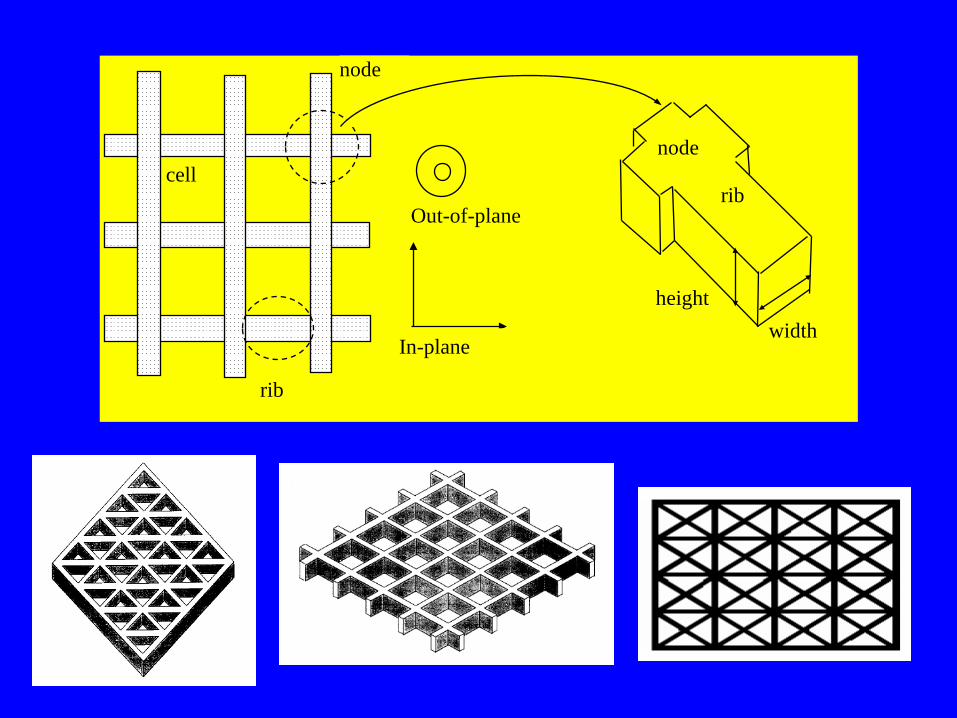
In-plane
Out-of-plane
cell
rib
node
node
rib
widthheight
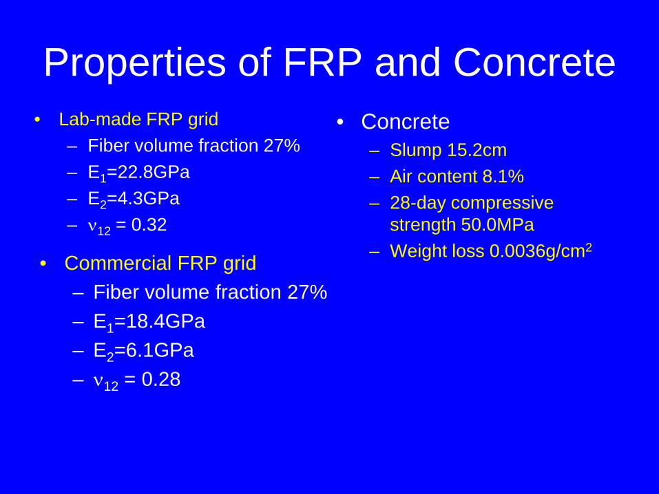
Properties of FRP and Concrete• Lab-made FRP grid
– Fiber volume fraction 27%– E1=22.8GPa– E2=4.3GPa– ν12 = 0.32
• Concrete – Slump 15.2cm– Air content 8.1%– 28-day compressive
strength 50.0MPa– Weight loss 0.0036g/cm2
• Commercial FRP grid– Fiber volume fraction 27%– E1=18.4GPa– E2=6.1GPa– ν12 = 0.28

Theoretical Studies using ANSYS Bridge Dimensions
Three Span Bridge Model
Four Girder model used for Modeling
A Typical AASHTO Type III Girder
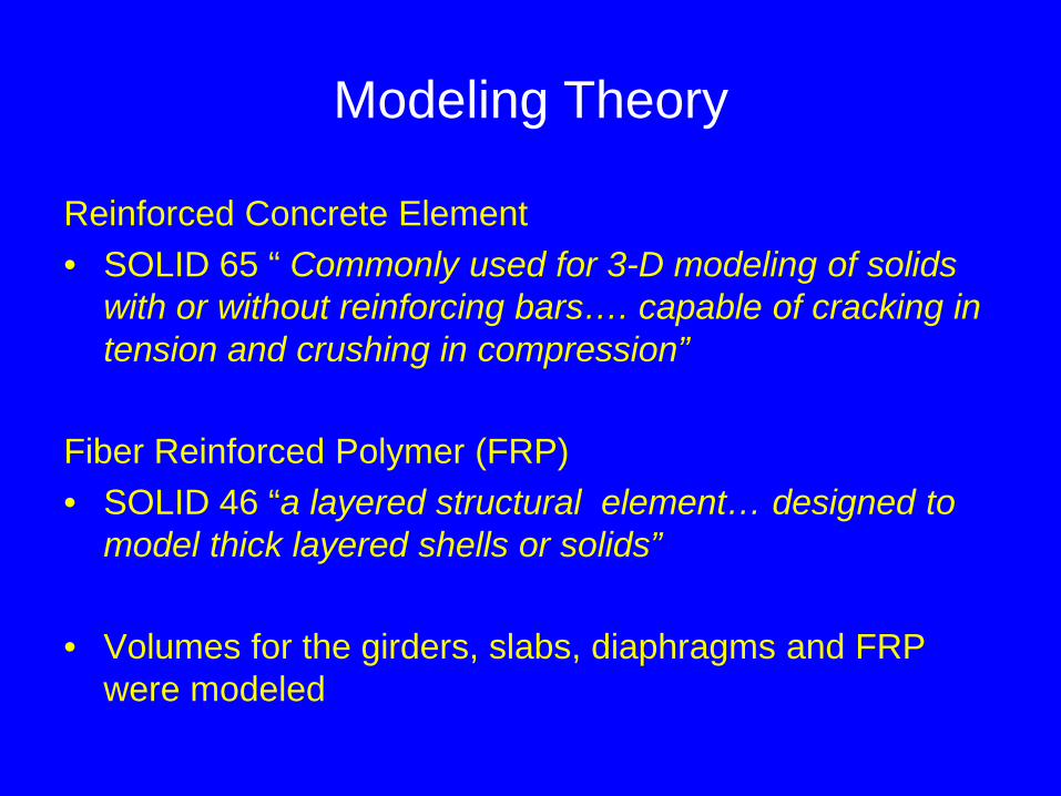
Modeling Theory
Reinforced Concrete Element• SOLID 65 “ Commonly used for 3-D modeling of solids
with or without reinforcing bars…. capable of cracking in tension and crushing in compression”
Fiber Reinforced Polymer (FRP)• SOLID 46 “a layered structural element… designed to
model thick layered shells or solids”
• Volumes for the girders, slabs, diaphragms and FRP were modeled

Modeling Theory
• Meshed Model
Modeling Theory
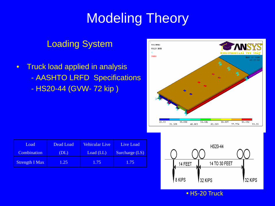
Loading System
• Truck load applied in analysis- AASHTO LRFD Specifications- HS20-44 (GVW- 72 kip )
• HS-20 Truck
Load
Combination
Dead Load
(DL)
Vehicular Live
Load (LL)
Live Load
Surcharge (LS)
Strength I Max 1.25 1.75 1.75
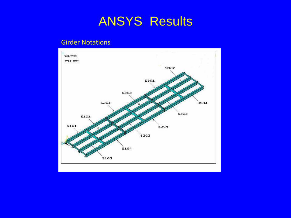
ANSYS ResultsGirder Notations
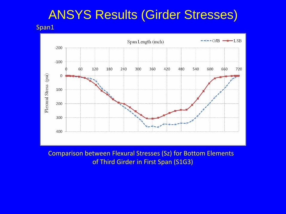
ANSYS Results (Girder Stresses)
Comparison between Flexural Stresses (Sz) for Bottom Elements of Third Girder in First Span (S1G3)
Span1
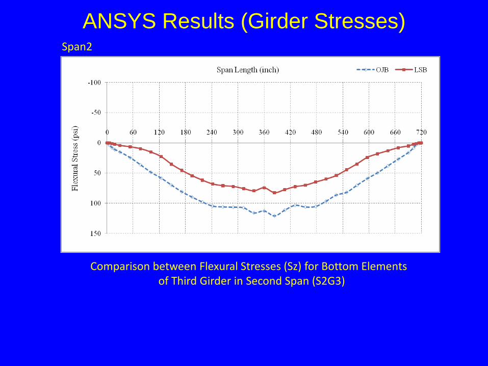
ANSYS Results (Girder Stresses)
Comparison between Flexural Stresses (Sz) for Bottom Elements of Third Girder in Second Span (S2G3)
Span2
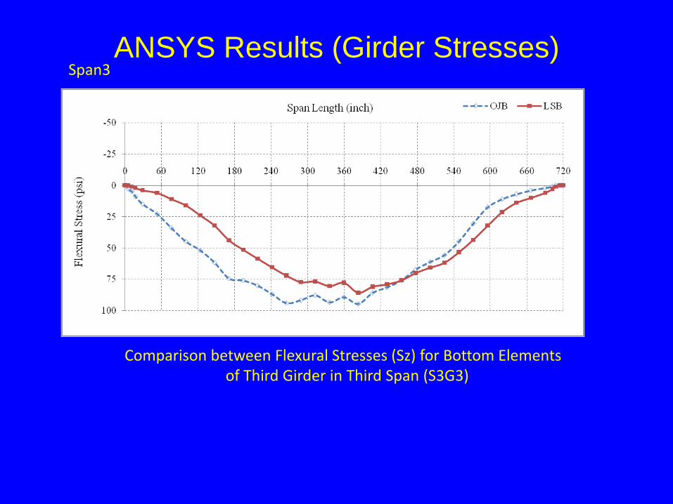
ANSYS Results (Girder Stresses)
Comparison between Flexural Stresses (Sz) for Bottom Elements of Third Girder in Third Span (S3G3)
Span3
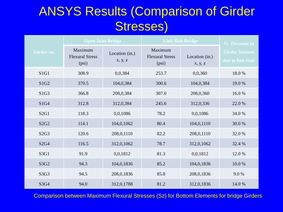
ANSYS Results (Comparison of Girder Stresses)
Girder no.
Open Joint Bridge Link Slab Bridge % Decrease in
Girder Stresses
due to link Slab
Maximum Flexural Stress
(psi)
Location (in.)x, y, z
Maximum Flexural Stress
(psi)Location (in.)
x, y, z
S1G1 308.9 0,0,384 253.7 0,0,360 18.0 %
S1G2 370.5 104,0,384 300.6 104,0,384 19.0 %
S1G3 366.8 208,0,384 307.0 208,0,360 16.0 %
S1G4 312.8 312,0,384 245.6 312,0,336 22.0 %
S2G1 118.3 0,0,1086 78.2 0,0,1086 34.0 %
S2G2 114.1 104,0,1062 80.4 104,0,1110 30.0 %
S2G3 120.6 208,0,1110 82.2 208,0,1110 32.0 %
S2G4 116.5 312,0,1062 78.7 312,0,1062 32.4 %
S3G1 91.9 0,0,1812 81.3 0,0,1812 12.0 %
S3G2 94.3 104,0,1836 85.2 104,0,1836 10.0 %
S3G3 94.5 208,0,1836 85.8 208,0,1836 9.0 %
S3G4 94.0 312,0,1788 81.2 312,0,1836 14.0 %
Comparison between Maximum Flexural Stresses (Sz) for Bottom Elements for bridge Girders
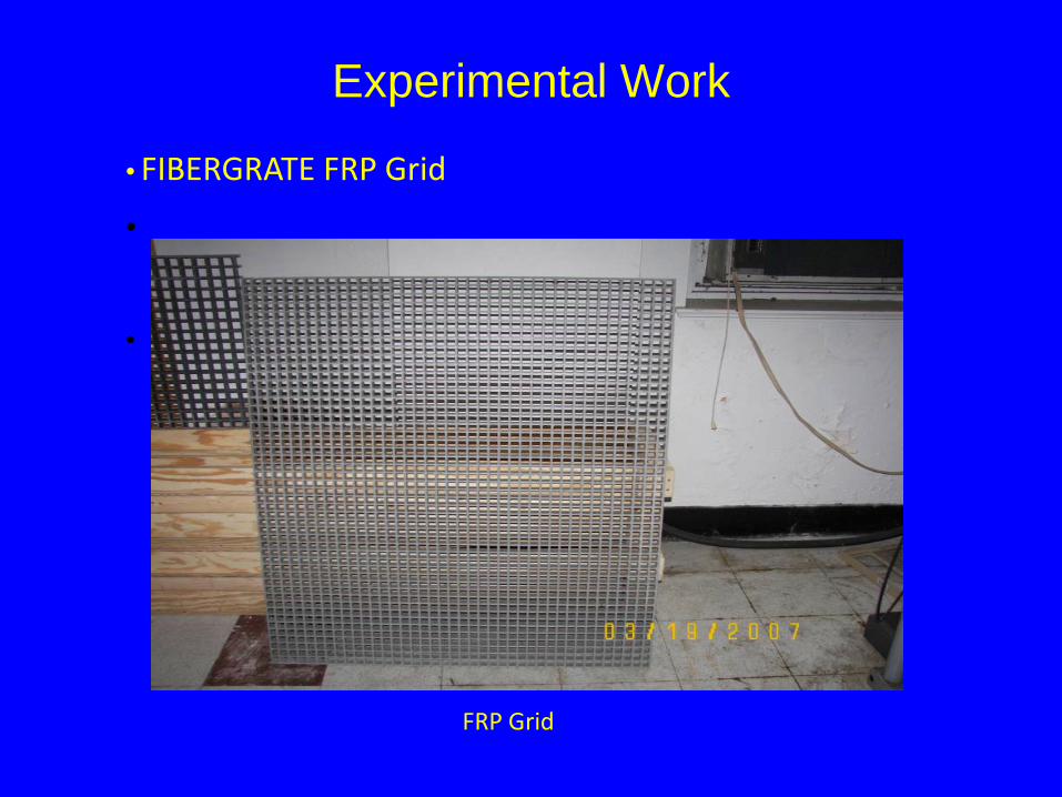
Experimental Work
•
•
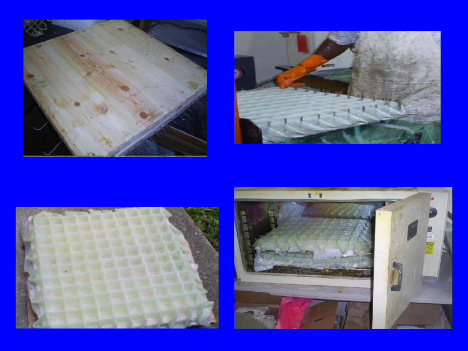
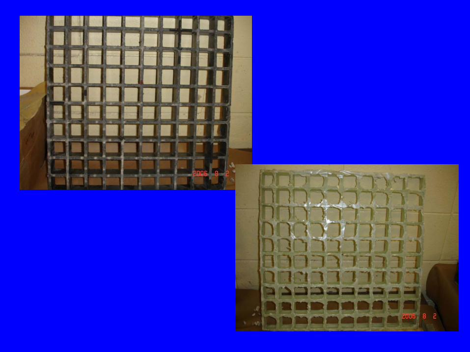
FRP Grid
• FIBERGRATE FRP Grid
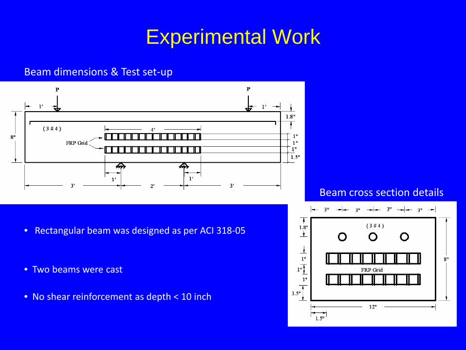
Experimental Work
• Rectangular beam was designed as per ACI 318-05
• Two beams were cast
• No shear reinforcement as depth < 10 inch
Beam cross section details
Beam dimensions & Test set-up

Experimental Work
• Instrumentation Plan
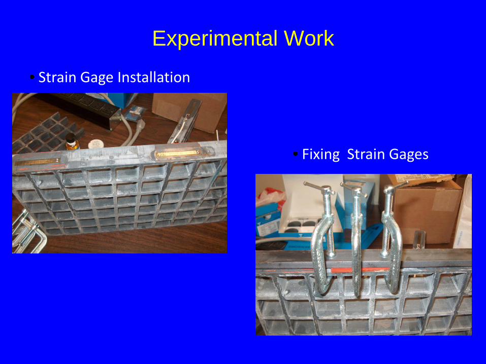
Experimental Work
• Strain Gage Installation
• Fixing Strain Gages

Experimental Work
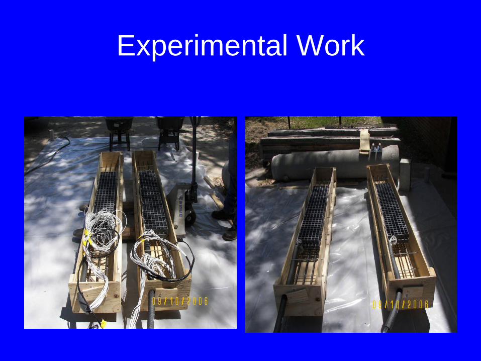
Experimental Work

Experimental Work
• Pouring the Concrete in Cylinders
• Cylinder Testing

Experimental Work
• Beam Testing
• Beam at Collapse
Experimental Results
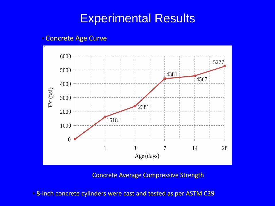
• 8-inch concrete cylinders were cast and tested as per ASTM C39
1618
2381
43814567
5277
0
1000
2000
3000
4000
5000
6000
1 3 7 14 28
F'c
(psi
)
Age (days)
• Concrete Age Curve
Concrete Average Compressive Strength
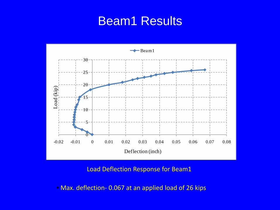
Beam1 Results
0
5
10
15
20
25
30
-0.02 -0.01 0 0.01 0.02 0.03 0.04 0.05 0.06 0.07 0.08
Load
(kip
)
Deflection (inch)
Beam1
Load Deflection Response for Beam1
• Max. deflection- 0.067 at an applied load of 26 kips
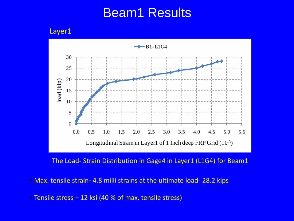
Beam1 Results
• Max. tensile strain- 4.8 milli strains at the ultimate load- 28.2 kips
0
5
10
15
20
25
30
0.0 0.5 1.0 1.5 2.0 2.5 3.0 3.5 4.0 4.5 5.0 5.5
load
)kip
)
Longitudinal Strain in Layer1 of 1 Inch deep FRP Grid (10-3)
B1- L1G4
The Load- Strain Distribution in Gage4 in Layer1 (L1G4) for Beam1
• Tensile stress – 12 ksi (40 % of max. tensile stress)
Layer1
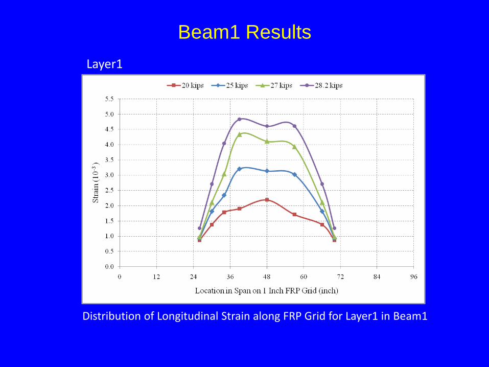
Beam1 Results
Distribution of Longitudinal Strain along FRP Grid for Layer1 in Beam1
Layer1
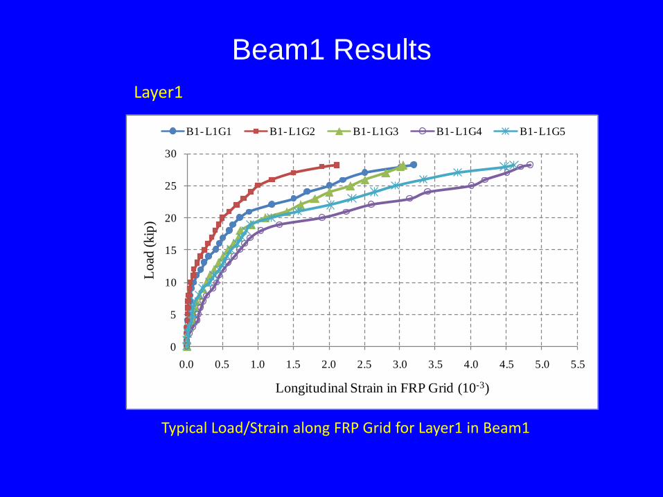
Beam1 Results
0
5
10
15
20
25
30
0.0 0.5 1.0 1.5 2.0 2.5 3.0 3.5 4.0 4.5 5.0 5.5
Load
(kip
)
Longitudinal Strain in FRP Grid (10-3)
B1- L1G1 B1- L1G2 B1- L1G3 B1- L1G4 B1- L1G5
Typical Load/Strain along FRP Grid for Layer1 in Beam1
Layer1

Conclusions • Durable link slabs for jointless bridge decks
based on using FRP Grid for reinforcement. Specifically the ductility of the FRP material can be utilized to accommodate bridge deck deformations.
• The results indicated that the technique would allow simultaneous achievement of structural need (lower flexural stiffness of the link slab approaching the behavior of a hinge) and durability need of the link slab.
• A cost-effective solution to a number of deterioration problems associated with bridge deck joints.
Recommendations• Durable jointless concrete bridge decks may be
designed and constructed with FRP grid link slabs.
• It is recommended that the link slab technique is used during new construction of bridge decks.
• It is recommended that the advantages of using the FRP Grid link slab technique in repair and retrofit of bridge decks are considered along with the amount of intrusive field work required to develop the required mechanical properties at the bridge deck joints.
Future Application• Field-level installation • Bridge selection, off-system small-span bridge with
expansion joints and RC deck on concrete girders• Linkslab design function of geometry of deck,
superstructure and substructure Information.• FRP grid
– Purchasing from manufacturer– If unavailable, lab-fabrication can be considered as an
alternative• Monitoring
• Installation of strain gages

Audience
Comments / Questions