Embed Size (px)
Citation preview

Pergamon
PII:S0967-0661 (96)00130-X
Control Eng. Practice, Vol. 4, No. 9, pp. 1241-1248, 1996 Copyright © 1996 Elsevier Science Lid
Printed in Great Britain. All rights reserved 0967-0661/96 $15.00 + 0.00
ELIMINATION OF POSITION-DEPENDENT DISTURBANCES IN CONSTANT-SPEED-ROTATION CONTROL SYSTEMS*
M. Nakano*, J.-H. She**, Y. Mastuo* and T. Hino***
*Department of Control System Engineering, Tokyo Institute of Technology, Tokyo 152. Japan **Department of Mechatronics Engineering, Tokyo Engineering University, Tokyo 192, Japan
***Hitachi Research Laboratory, Hitachi Ltd., Ibaraki 319-12, Japan
(Received October 1995; in final form March 1996)
Abstract: This paper describes a new approach to eliminating position-dependent disturbances in constant-speed-rotation control systems. Focusing on the fact that this kind of disturbance constitutes a periodic function of the rotational angle, a new concept called the "position domain" is introduced, and the design of the proposed control system is carried out in the position domain instead of the time domain, so as to eliminate such disturbances completely, regardless of any changes in the rotational speed.
Keywords: Fluctuations, periodic waves, disturbance rejection, speed control, learning control, H-infinity control, dead-beat control
1. INTRODUCTION
High precision and the desired command response are very important requirements of constant-speed- rotation control systems. However, fluctuations in the rotational speed, which are frequently caused by position-dependent disturbances, have hindered all efforts to improve the precision of such systems. These fluctuations are caused by such things as the non- uniformity of the magnetic flux in DC motors, and eccentricity in the structure of the rotation systems and cutting force in noncircular cutting processes.
There are many reports on reducing such effects by improving the mechanism (Gotou and Kobayashi, 1983; Murai et al., 1989) or using an active control scheme (Kobayashi et al., 1990). Of particular interest is the method developed by Kobayashi et al. (1990), who considered position-dependent disturbances as periodic functions of time for a given rotational speed, and developed a repetitive controller in the time
*This work was supported in part by the Ministry of Education of Japan under grant number 04650365.
domain. However, that method was not efficient enough when the speed setting was changed, though it was very effective for a constant speed. So some special techniques, such as a phase-locked loop, had to be used to maintain high control precision,
This paper proposes a systematic approach, focusing on the basic fact that this kind of disturbance constitutes a periodic function of the rotational angle. A new concept called the "position domain" is first introduced, and the design of the proposed control system is carried out in the position domain instead of the time domain so as to eliminate such disturbances completely, regardless of the rotational speed. Finally, some experimental results are shown to demonstrate the effectiveness of this approach.
The position-domain method was independently proposed by Tsao et al. (1989) and She et al. (1990). Tsao et al. (1989; 1991) used it to suppress the effect of cutter runout on the maximum tangential cutting force in face milling by actively varying the spindle speed. However, in a previous study (She et aL, 1990) and also in the present one, it is used to make the
1241

1242 M. Nakano et al.
effect of speed fluctuations as small as possible when a constant-speed-rotation control system is perturbed by position-dependent disturbances.
Notation and Definitions ,t. : delay operator (= z-l).
R H , :set of real-rational functions in Z which have no poles within or on the unit circle.
R[Z]: ring of polynomials in ~. ( c R/-/,). R '~×n: set of m-row and n-column matrices.
IIG(;L)L := sup [a(eJ*)[ (a(;t)~ R n ) . O_<~<_2n
a+(,~): real monic polynomial (the coefficient of the highest order is one) having no zeros outside the unit circle in the complex plane.
a ( Z ) : real polynomial having no zeros within or on the unit circle in the complex plane.
a*(A) := a(;Vl).
t. So the stability defined in the position domain is the same as that defined in the time domain.
Throughout this paper, Condition (2) will be assumed to be satisfied.
Consider a linear time-invariant rotation system with two inputs and one output. The state-space description in the time domain is given by
dXd(t t = Ax(t) + Bu(t)[ ,
to(t) = ~x(t) + v(t) J (3)
where u(t): control input, v(t): position-dependent disturbance, to(t): rotational speed.
2. SYSTEM MODELING IN THE POSITION DOMAIN
In the problem considered here, the position-dependent disturbances to be eliminated are periodic functions of the position, or in other words the rotational angle, which is defined as
O := l~to(t)dt, (1)
where to(t) is the rotational speed. Since the disturbances are based on the rotational angle, it is clearly more convenient to formulate this problem in terms of the rotational angle, rather than time. This leads to the concept of the "position domain", which is defined as follows (She et al., 1990): Definition: The position domain is a set in which every element is a function of the rotational angle.
To obtain a model in the position domain, the following condition for the transformation from the time domain to the position domain must be satisfied. Transformation condition: There exists a transformation from the time domain to the position domain if and only if the direction of rotation is unchanged. Without loss of generality, if the direction of rotation is designated the positive direction, then the condition can be expressed as:
t o ( t ) = - - > O ; V t > 0 . (2) dt
Remark 1: Condition (2) follows directly from the inverse function theorem (Boothby, 1975). It guarantees the existence of the inverse function t := t(O) of 0 = O(t). Remark 2: According to Condition (2), the rotational angle 0 is a monotonically increasing function of time
The following assumptions, which are standard in repetitive control, are also assumed to be satisfied. Assumption 1: (A,B) is stabilizable, and (A,~) is detectable.
Assumption 2: has no zeros on the unit
circle.
In view of (2), the relationship between the time domain and the position domain can be summarized as
t := t(O)
u = u(t) = u(t(O)):= ~(0)
v = v(t) = v(t(O)):= ~(0)
co = to(t) = to(t(O) ) := tb(0)
x = x(t) = x(t(O)):= ~(0) dx(t) dYe(O) dO dYe(O)
- = ~ o ( o )
,. (4)
According to this transformation, especially in the position domain, the position-dependent disturbance ~(0) constitutes a periodic function with the period being a constant. So, the effect of a disturbance on the rotational speed should be eliminated by a repetitive controller (Hara et al., 1988; Tomizuka et al., 1989) with the same period as that of the disturbance.
Substituting (4) into (3), the model of the rotation system in the position domain is:
. . . . d~(0) A~(O)+ B~(O)] to(u) dO =
?o(O) = ~ ( O ) + ~,(0) I"
(5)
This model is nonlinear. One way to design a controller based on linear system theory is to linearize (5) around the equilibrium point ((o(O),dMO)/ dO) =( to , O). Some simple calculations yield the following linear model.
Disturbance Elimination for Speed Control 1243
where
--d-if- -d~(e) _ ~c(O) + h~(O) t '
~b(O) = ~x(e) + ~(o) J (6)
, ~ = A , ~=B, and~=!P. (7) tot (Dr
Since the parameters in (7) are dependent on therotational speed at the equilibrium point, the characteristics of the rotation system will change when the speed setting is changed, and this will degrade the response of the system. Consequently this kind of influence must be made as small as possible through the design of an efficient controller.
The stabilizability and detectability are preserved under the domain transformation. The reason is as follows. If the Laplace operators corresponding to the time domain and the position domain are s, and s, respectively, then the transfer function of the linear (linearized) plants in the time domain and the position domain are
P ( s , ) = [ ~ O O ] = ~ ( s , l - A ) -~B, (8)
and
!P(torsl - A)-~ B,
(9)
respectively. The corresponding poles and zeros are given by
l-Al:O) = {s, : ~(adj(s,l - A)-')B = O}J'
(10)
and
r = {s : ~ ° , s I - AI = 0}
= {s : ~P(adj(to, sl - A)-I)B = o}J (11)
3. C O N T R O L S Y S T E M D E S I G N
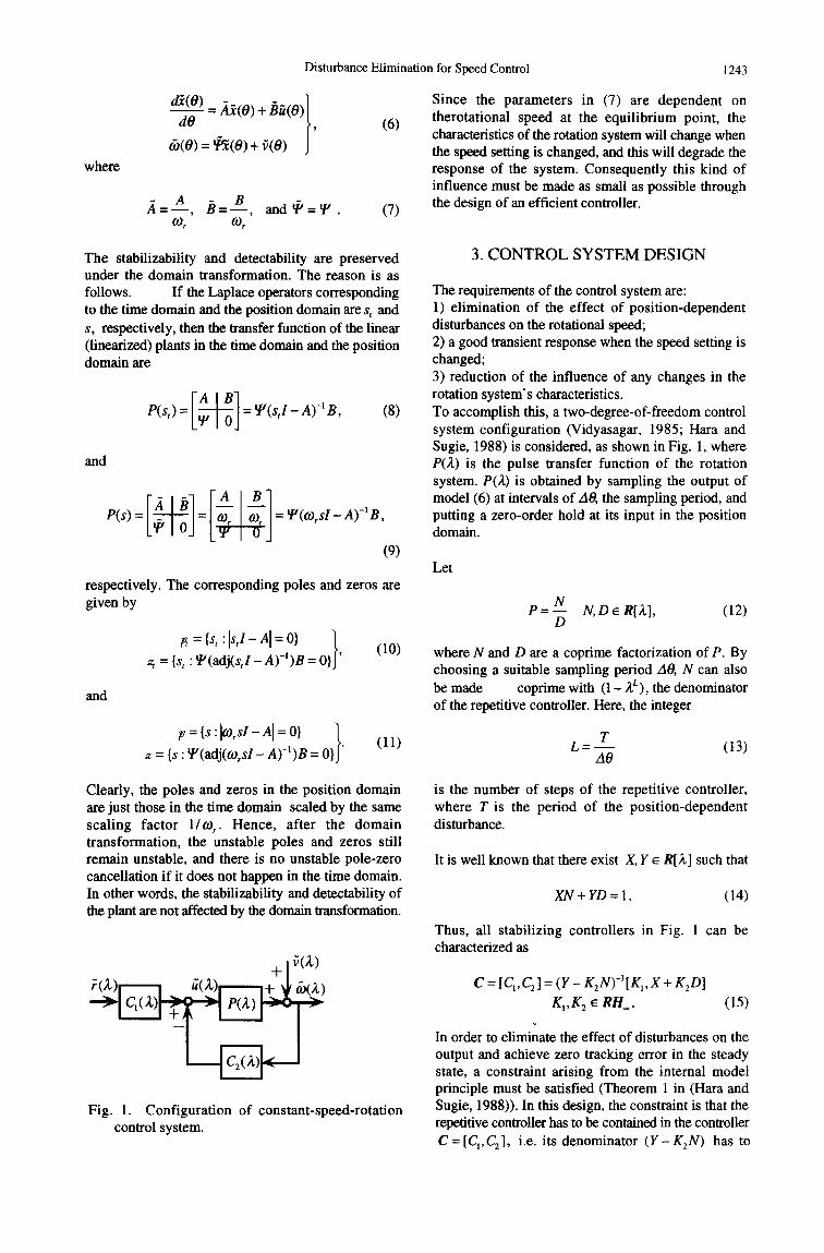
The requirements of the control system are: 1) elimination of the effect of position-dependent disturbances on the rotational speed; 2) a good transient response when the speed setting is changed; 3) reduction of the influence of any changes in the rotation system's characteristics. To accomplish this, a two-degree-of-freedom control system configuration (Vidyasagar, 1985; Hara and Sugie, 1988) is considered, as shown in Fig. 1, where P(~) is the pulse transfer function of the rotation system. P(£) is obtained by sampling the output of model (6) at intervals of AO, the sampling period, and putting a zero-order hold at its input in the position domain.
Let
p = N N,D~R[,~], (12) D
where N and D are a coprime factorization of P. By choosing a suitable sampling period AO, N can also be made coprime with (1 - £L), the denominator of the repetitive controller. Here, the integer
T L = m (13)
A0
Clearly, the poles and zeros in the position domain are just those in the time domain scaled by the same scaling factor 1/to,. Hence, after the domain transformation, the unstable poles and zeros still remain unstable, and there is no unstable pole-zero cancellation if it does not happen in the time domain. In other words, the stabilizability and detectability of the plant are not affected by the domain transformation.
+[~(Z)
Fig. 1. Configuration of constant-speed-rotation control system.
is the number of steps of the repetitive controller, where T is the period of the position-dependent disturbance.
It is well known that there exist X, Y ~ R[A,] such that
XN + YD = 1. (14)
Thus, all stabilizing controllers in Fig. 1 can be characterized as
C = [CI, C2] = (Y - K2N)-~[K1, X + K2D] K1,K 2 ~ Rl-l . (15)
In order to eliminate the effect of disturbances on the output and achieve zero tracking error in the steady state, a constraint arising from the internal model principle must be satisfied (Theorem 1 in (Hara and Sugie, 1988)). In this design, the constraint is that the repetitive controller has to be contained in the controller C = [C1,C2], i.e. its denominator ( Y - K2N) has to
1244 M. Nakano et al.
contain the factor (1 - ;¢). is a suitably chosen weighting function.
Assumption 2 guarantees that N and (1- ,~L)D are coprimes. So, there exist X, Y' e R[X] such that
XN+(1 -3 f )Y 'D= 1. (16)
If Y is written
Y = (1 - ~LL)Y ' (17)
On the other hand, suppose the rotation system' s pulse transfer function is P for the standard rotational speed and /3 for any other rotational speed. Then, the input- output transfer function of the control system can be written as
G~= PC~ (24) l + P C 2
and K 2 ~ RH. is restricted to
K2=(1-gL)K; K ; e R H . , (18)
then the above constraint can be satisfied.
Finally, the controller is parametrized as
C = [C~,C2] = (1 - ZL)-~(Y ' - K~N)-t *
[K,,X + (1 - ZL)K;D]
K,,K; e RH.. (19)
In view of (19), the following formulation is obtained:
PC~ = NK 1, (20) ~ ---~ (b • G~ = l + P C 2
1 - (1 - AL)D(Y ' - K;N). ~ ----> (o : G~ - I + PC 2
(21)
Since G~ is dependent only on parameter K~ and is
independent of parameter K~, the effect of disturbances can be reduced by choosing a suitable K~. Similarly, since G,~ is dependent only on parameter/(1, choosing
a suitable K 1 will yield the desired input-output characteristics.
3.1 Design of Parameter K~
From (21), the effect of position-dependent disturbances on the rotational speed of the rotation control system is given by
1 &~ = - - ~ = S~, (22)
1+ PC 2
/3q G'~ = 1 + PC 2 " (25)
The change in the input-output transfer function caused by a change in the speed setting is given by
_ 1 / 3 - e / 3 - e = S (26)
G~ 1+PC2 /3 /3
It has been shown that robustness can be achieved by making the sensitivity function as small as possible (Zhao and Kimura, 1988).
For the above reasons, the robustness index here is defined as
J2 = I I_~T~L S = [IWD(Y' - K~N)[[. (27)
and the parameter K~ e RH. is chosen so as to yield inf J2. The solution is given by Gu et al. (1989),
g~ eR//_
Iglesias et al. (1990) and Iglesias and Glover (1991).
3.2 Design of Parameter K~
/(1 is determined using the method proposed by Horiguchi et al. (1989) to achieve dead-beat control that moderately restricts the input-output error and the control input within the settling time. It can be summarized as follows.
Rewrite P as
P= X'~b- X"(b° +blX +'"+b~]~) (28)
a a o + al~ +.. . + a,~," '
where S denotes the sensitivity function of the control system and is defined as
where ao,bo ~ 0 and a and b are coprimes. Then N and D in (12) become
1 S = ~ . (23)
I + PC 2
From (22), it is clear that the goal of eliminating disturbances can be achieved by making IIWS/(1 - ;t L ~1. as small as possible, where W ~ R H ,
N=2mb; D = a . (29)
If b is factored into
b = b_b+, (30)

Disturbance Elimination for Speed Control 1245
and the number of settling steps is chosen to be/.t, then the input-output error is
~ := ~ - t b 1-NK1 -~" -~- EeiAi• (31)
1 - ~ i=o
The deadbeat constraint on K~ can be stated as follows: Constraint on K~:given that the speed setting is changed in discrete steps, there exists a KI ~ RH. that makes the input-output error vanish after a finite number of steps if and only if there exists a polynomial f ~ R[~,] satisfying
/z
1 - (1 - ;L)(Z ~,;0 = A,mb+f. (32) i = 0
To optimize the transient response, the transient performance index is defined as
J~ = m + Fr(BrErEB + p2Q)F. (37)
The polynomial f ~ R[2] that minimizes J~ is
(BrErEB + p2Q)-le F= b+(1)er(BrEtEB+p2Q)_~e, (38)
where,
e= [1 1 .'. 1] r ~ R ~r+'×l.
The parameter 1(1 e RH. of the dead-beat controller and the minimum of J~ are given by
1 •(39)
minJ 1 =m+ b+(1-~ffrE?EB+ pZQ)_le J
- 2 2 - 2 Jt = E ([e~[ + p [Au~[ ), (33)
i = 0
where
A~ := (1 - A)~ = £ zl~iA,', iffiO
p • weighting coefficient.
Defining
I÷ b+=Xb:X' i=O
a a" q V V. : - - K + - -
Y
i = 0
, q = £qi;d - i = 0
y = / z - m - / + +1
B =
F = [ f o f~ - +
b; o
b~ + b o
0 b2
E R (t÷ +Y+l)×O'+l)
(34)
(35)
It is well known that minJ~ is a monotonically decreasing function of/a. So, min,/l can be improved by increasing the number of settling steps/z.
4. EXPERIMENTS
The experimental system is shown in Fig. 2. It consists of two DC motors, a computer with a 68000-series CPU, and the relevant interface hardware. One of the DC motors was used as a controlled object. The other was used to generate a position-dependent disturbance.
In this experiment, the system was subjected to a position-dependent torque disturbance
v(O(t)) = 0.01898(sin O(t) + 0.5 sin __,t.TJ~Ot 3 5 5
+ 0.25sin ~tt.)). 5
(40)
Thus, the period of the position-dependent disturbance is
T= 10r:(rad). (41 )
The plant model in the time domain is
and
I q~i ql " " qr]
Q = ql ."" ."" i ~R(r+l)×(r+l) "" " ' q l
r "'" ql q0
E = " E R (l +y+l)x(m • . i + + + y )
0 1
(36)
P(s,) = K } ~t +1
K = 1•058; Z = 0.03894 (42)
with the input being the command voltage and the output being the rotational speed.
The standard rotational speed setting was
co r = 104.7(rad/s). (43)
The transformation introduced in Section 2 yielded a enables the performance index ,/1 to be written as

1246 M. Nakano et al.
Rotational Speed
6 000 mputer [g_lUp-Down 1'
- - - I C°unter [ R o t a t i o n a l ~
'¢ ~ ¢ Angle ,k7 ¢
Encede;' l Tachogenerator
Speed C o m m a n ~
Fig. 2. Experimental setup.
Controlled Disturbance ' Motor Generator
dotor M : o ~ )river l:h
, Current Command
linear plant model in the position domain, which was sampled at intervals of
AO=l.257(rad) (44)
to obtain the pulse transfer function of the nominal rotation system:
,::L l = 1.361; fl = -0 .3820J
The number of steps of the repetitive controller is
10~r L = = 25, (46)
A0
Using the approach developed in Section 3, a repetitive controller for (45) can be designed as follows.
4 0 : i i
30 q . ........................... i! !i ............................ [ i I ..............
20-4 ........... ,. ............... i ............... i .............. *. .............. + ............. t O i [ : : : 1 10 .......... *-, ........... i..min Jl (~)=5.66376 ..........
l ! " , ~ ~ ,. i o - i i i i i /
5 10 15 20 25 30
/2
Fig. 3. Relationship between min J~ and/2.
20
0 ",'t~
-20
• .~ -40
"~ -60 m 0.001 0.01 0.1 10
0
Fig. 4. Sensitivity characteristics of the designed constant-speed-rotation control system.
1 K~ - (51) a # ( z - a )
The relationship between/2 and min J~ was plotted for various numbers of settling steps to determine a suitable number. The number turned out to be 10, as can be seen in Fig. 3 for
p = 1. (52)
First, bringing in the factorizations of P yields
p = N ~,mb
D a D = ~ , - a ; N = f l Z } a = a o + a , ~ , = - a + ) ~ ; b = b o =fl ; m = l ' (47)
Then, according to (30)
b_ = #; b÷ = 1 (48)
is obtained. Solving (16) gives
1 + a A L-1 - ~L 1 X = ; Y ' = - - - . (49) a/~ a
Letting
W=l,
and solving (27) yields the parameter K~:
(50)
It is clear that the performance index min J~ decreases monotonically with respect to/2. Since
is very close to
min J~(10) = 5.90275 (53)
min J1 (~) = 5.66376, (54)
/2 = 10 (55)
is an appropriate value. Thus the parameter K1 is given by
g I = [k o k a -.. kaol[1 Z .., ~lOlr (56)
[ko k, .../,101 = [-0.8789 - 1.451 - 1.778 - 1.915
- 1.907 - 1.793 - 1.602 - 1.354
- 1.064 - 0.7395 - 0.3849].

Disturbance Elimination for Speed Control 1247
120 ..................... i ..................... ~. ..................... [ .....................
..................... i ..................... s ..................... ~ ..................... 40
0
0.0 0.5 1.0 1.5 2.0
Time (sec)
0 . 0 4 -[ . . . . . . . . . . . . . . . . . . . + . . . . . . . . . . . . . . . . . . . i . . . . . . . . . . . . . . . . . . . . i . . . . . . . . . . . . . . . . . . . .
0 . 0 2 . . . . . . . . . . . . . . . . . . . ~ . . . . . . . . . . . ~ . . . . . . . . . . . . . . . i . . . . . . . . . . . .
o.oo . -o.o -t ................... i ........ _ o . o , - ] ................... i ................... i ................... i ...................
0.0 0.5 1.0 1.5 2.0
Time (sec)
12o l::!:::::::::::::::::i::: 80 - without:control---- i .................... + ....................
400 •i!i!i!i)!!!)ii)!i!!!i!!!i!ii)i!!!!!!!!!!!!!!!!!!!iii!)!!!!!i!i!•!!!!!)!ii!!!!!!!)) 0.0 0.5 1.0 1.5 2.0
Time (sec)
8
200 . /
15o -~ . . . . . . . . . . . . . . . . . . . . ! I . . . . . . . . . . . . . . . . i . . . . . . . . . . . . . . . . . . . . T . . . . . . . . . . . . . . . . . . . .
~ o o ~ - ' - ................. i ................... i .................... 50 .................... 1 ..................... i .................... " .................... .................... ! .....
0.0 0.5 1.0 1.5 2.0
Time (sec)
0.04 -1--- ................ + ................... ! .................... i .................... 0.02 - - ............ ! ........... i .......... i .............
-0.02 " l ........ V - - ~ " I I - ~ - - I -0.04-. I . .......... " ~ ...................
0.0 0.5 1.0 1.5 2.0
Time (sec)
200 . , , ,,
150-~ .................... i----F-------- I ............... T .................... ~ 0 0 ~ ................................... ! ....................
5 o .................... i ..................... i .................... i ....................
0 q .................... .............. i 0.0 0.5 1.0 1.5 2.0
Time (sec)
/ ' 1 2 0 - , : .................. ~ , x ...... T = ........... ~ ....................
80 . I : :2 : : :2 : [ :2 : : i~2 : : :2 :21 : :2 :22 : ' , [with control .............. ~ ..................... i .....................
400 I•••••••••••••••••••••••••••••••••••••••••j.•••••••••••••••••••••i••••••••••••••••••••
0.0 0.5 1.0 1.5 2.0
Time (sec)
Fig. 5 Response to disturbance for a standard speed setting.
The sensitivity characteristics of the designed constant- speed-rotation control system are shown in Fig. 4. It can be seen that the designed control system has a sensitivity of zero at integer multiples of the frequency of the posit ion-dependent disturbance. Moreover, it has low sensitivity at low frequencies. It is clear that the effects of the position-dependent disturbances were completely eliminated.
Fig. 6 Response to change of the speed setting.
was el iminated after the second period, and the rotational speed tracked the command input without steady-state error.
In Fig. 6, the rotational speed was changed from 104.7 rad/s (1000 rpm) to 157.1 rad/s (1500 rpm). Even though this was different from the standard speed, the effect of the disturbances was still eliminated completely, and the speed tracked the input without s teady-state error. This demonst ra tes that the fluctuations caused by disturbances can be eliminated, even when the speed setting is changed.
For comparison, a controller was designed in the time domain. The experimental results in Fig. 7 show that the fluctuations are not sufficiently suppressed when the speed setting is different from the standard speed.
The experimental results are shown in Figs. 5, 6 and 7.
In Fig. 5, the command input was 104.7 rad/s (1000 rpm). After the system reached the steady state, the position-dependent disturbances (40) were input. It can be seen from the open-loop response that the disturbances exerted a marked inf luence on the rotational speed, causing it to fluctuate. When rotation control was applied, the influence of the disturbances
5. CONCLUSIONS
In c o n s t a n t - s p e e d - r o t a t i o n con t ro l sys tems , fluctuations in the rotational speed are often caused by p o s i t i o n - d e p e n d e n t d i s tu rbances . T h e s e disturbances are periodic functions of the rotational angle. Within this framework, this paper introduces a new concept called the position domain, and describes a new approach to eliminating this kind of disturbance, even when the rotational speed setting is changed. The validity of the present method has been

1248 M. Nakano et al.
r~
200 ] '
1 5 0 - I .................... i T ............ ~ .......................................
1 0 o i ................. i .................... T . . . . . . . . . . . . . . . . . . . .
0.0 0.5 1.0 1.5 2.0
Time (sec)
0.04 - 0.02 - 0 . 0 0 -
- 0 . 0 2 - -0.04 -
. . . . . . . . . . . . . . . . . . . . ~ . . . . . . . . . . . . . . . . . . . ~ . . . . . . . . . . . . . . . . . . . ! . . . . . . . . . . . . . . . . . . .
. . . . . . . . . . . . . . . . . . . . ~- . . . . . . . . . . . . . . . . . . . ~- . . . . . . . . . . . . . . . . . . . . 1 . . . . . . . . . . . . . . . . . . . L I I
i I I 0.0 0.5 1.0 1.5 2.0
Time (sec)
200
1oo ii ii ii ii iiiiiill ii ii ii ii ii!i ii iiiiiiiiiiiiii '° t o ................... iiiil.
0.0 0.5 1.0 1.5 2.0
Time (sec)
Fig. 7 Response of constant-speed-rotation control system designed in the time domain.
demonstrated by experiments.
Acknowledgment: The authors are extremely grateful to Dr. Shigeru Futami of Yaskawa Electric Co. for his help with the experiments, and also to the reviewers for their careful reading of the manuscript and their helpful suggestions.
REFERENCES
Boothby, W. M. (1975). An Introduction to Differentiable Manifolds and Riemannian Geometry, Academic Press.
Gu, D. W., M. C. Tsai, S. D. O'Young and I. Postlethwaite (1989). State-space formulae for discrete--time H" optimization. Int. J. Contr., 49, 1683-1723.
Gotou, M. and K. Kobayashi (1983). An Analysis of the Cogging Torque of a DC Motor and a New
Reducing Technique. Trans. of lEE J, 103-B, 711-718.
Hart, S., Y. Yamamoto, T. Omata and M. Nakano (1988). Repetitive Control System: A New Type Servo System for Periodic Exogenous Signals. IEEE Trans. on Automatic Control, 33, 659-668.
Hart, S. and T. Sugie (1988). Independent Parameterization of Two-Degree-of-Freedom Compensators in General Robust Tracking Systems. IEEE Trans. on Automatic Control, 33, 59-67.
Horiguchi, K., T. Nishimura, A. Nagata and H. Tomita (1989). Two-Degrees-of-Freedom Dead-Beat Control considering Transient Responses. Trans. of the Society of Instrument and Control Engineers, 25, 1046-1053.
Iglesias, P. A., D. Mustafa and K. Glover (1990). Discrete time H" controllers satisfying a minimum entropy criterion. Sys. & Contr. Lett., 14, 275-286.
Iglesias, P. A. and K. Glover (1991). State-space approach to discrete-time H" control. Int. J. Contr., 54, 1031-1073.
Kobayashi, F., S. Hara and H. Tanaka (1990). Reduction of Motor Speed Fluctuation Using Repetitive Control. CDC Proceedings, Honolulu, Hawaii, pp.1687-1702.
Murai, Y., Y. Kawase, K. Ohashi, K. Nagatake and K. Okuyama (1989). Torque Ripple Improvement for Brushless DC Miniature Motors. IEEE Trans. Ind. Appl., 25, 441-450.
She, J.-H., M. Nakano and Y. Matsuo (1990). A New Approach to Reject Angle Dependent Disturbances in Constant-Speed-Rotation Control Systems. The 33rd Japan Joint Automatic Control Conference, pp.441-442.
Tomizuka, M., T. C. Tsao and K.-K. Chew (1989). Analysis and synthesis of discrete-time repetitive controllers. Trans. ASME, J. Dynam Sys, Measu, Contr, 111,353-358.
Tsao, T. C., J. B. Burke and P. M. Ferreira (1989). Control of Radial Runout in Face Milling. Symposium on Control Issues in Manufacturing Processes, American Society of Mechanical Engineers Winter Annual Meeting, San Francisco, pp.99-105.
Tsao, T. C. and K. C. Pong (1991). Control of Radial Runout in Multi-Tooth Face Milling. Trans. of the North American Manufacturing Research Institute of SME, pp.183-190.
Vidyasagar, M. (1985). Control System Synthesis: A Factorization Approach, The MIT Press.
Zhao, Y. and H. Kimura (1988). Two-degrees-of- freedom dead-beat control system with robustness. Int. J. Control, 48, 303-315.
![SCISCITATOR 2015 · [1]. Riverine communities experience two main types of disturbances: natural disturbances and anthropogenic disturbances. Natural disturbances in riverine ecosystems](https://img.pdfslide.net/doc/110x75/5f27dd3959f0c41da22eeec5/sciscitator-1-riverine-communities-experience-two-main-types-of-disturbances.jpg)