Embed Size (px)
Citation preview
Master Meter, Inc. ❘ 101 Regency Parkway, Mansfield, TX 76063 ❘ T: 817-842-8000 ❘ MasterMeter.com
e L i n x ™ P R O G R A M M I N G
Category: Registers & Endpoints
Type: eLinx Interpreter
Issue: Programming

2
eLinx Interpreter Programming Manual
Introduction
This document will walk you through how to properly program your eLinx™ Interpreter®. PLEASE NOTE: eLinx Technician Version 1.3.0 software should be used when programming.
Installation:
After installing eLinx Technician software (See Figure 1), plug in the eLinx Programmer (See Figure 2) to your computer. After a few seconds the programmer will begin installing the correct driver. You are now ready to being using eLinx Technician software.
Figure 1: eLinx Technician Software

3
eLinx Interpreter Programming Manual
Figure 2: eLinx Programmer
Communication Port:
Within the Unit Control menu located in the top left-hand corner of your screen, you will find the Communication Port (COM Port) command (See Figure 3). Please ensure the correct COM Port is selected for the eLinx Programmer. If the correct COM Port has not been selected, you will need to manually locate this communication port within the Device Manager menu of your computer.
Figure 3: COM Port
Read & Write:
The Read and Write tabs (See Figure 4), located within the Unit Control menu are the two main tabs you will be using.
Figure 4: Read & Write Tabs

4
eLinx Interpreter Programming Manual
Programmability Fields:
The programmable design of eLinx Interpreter allows this register to work on most any meter and connect to most any AMR/AMI system with common bayonet-style register housing. Please use Figure 5 below as a reference for the Programmability Fields section of this document.
Figure 5: eLinx LCD Display Below you find a list of fields to take note of (See Figure 6).
Figure 6: Programmability Fields
5
eLinx Interpreter Programming Manual
1. CW Read – Reading to be programmed (If new installation set to “0”) 2. Number of digit to show – Number of digits to be shown (One to nine digits) 3. Start From digit – Starting digit 4. Main Display Units – Reading range to be used (Four multiplier options available) 5. IR Rotation Flag – Direction the measuring chamber spins with water flow (CCW-
Normal (MM) is most commonly used for Master Meter water meters) 6. Meter Decimal Point – Decimal place value to be shown (Also known as the Unit of
Measure. See Figure 5) 7. Flow Decimal Point – Decimal place value to be shown in the Rate of Flow (Also the
unit of measure for water flow) window 8. Meter Gear-Ratio – Found in 3G Tech NET** 9. Flow Ratio – Gear ratio of the meter (Gallons or Cubic Feet)
PLEASE NOTE: In order to view Rate of Flow, the desired unit of measure must be entered in the Meter Gear Ratio field (Gallons is the most common Unit of Measure used). After all parameters have been selected, attach the eLinx Programmer to the eLinx Interpreter. There are multiple ways to attach to eLinx. Please see connectivity options listed below:
1. Sensus TR/PL Sensor w/Wire 2. Itron Inline Connector 3. Nicor Connector 4. Bare Wires
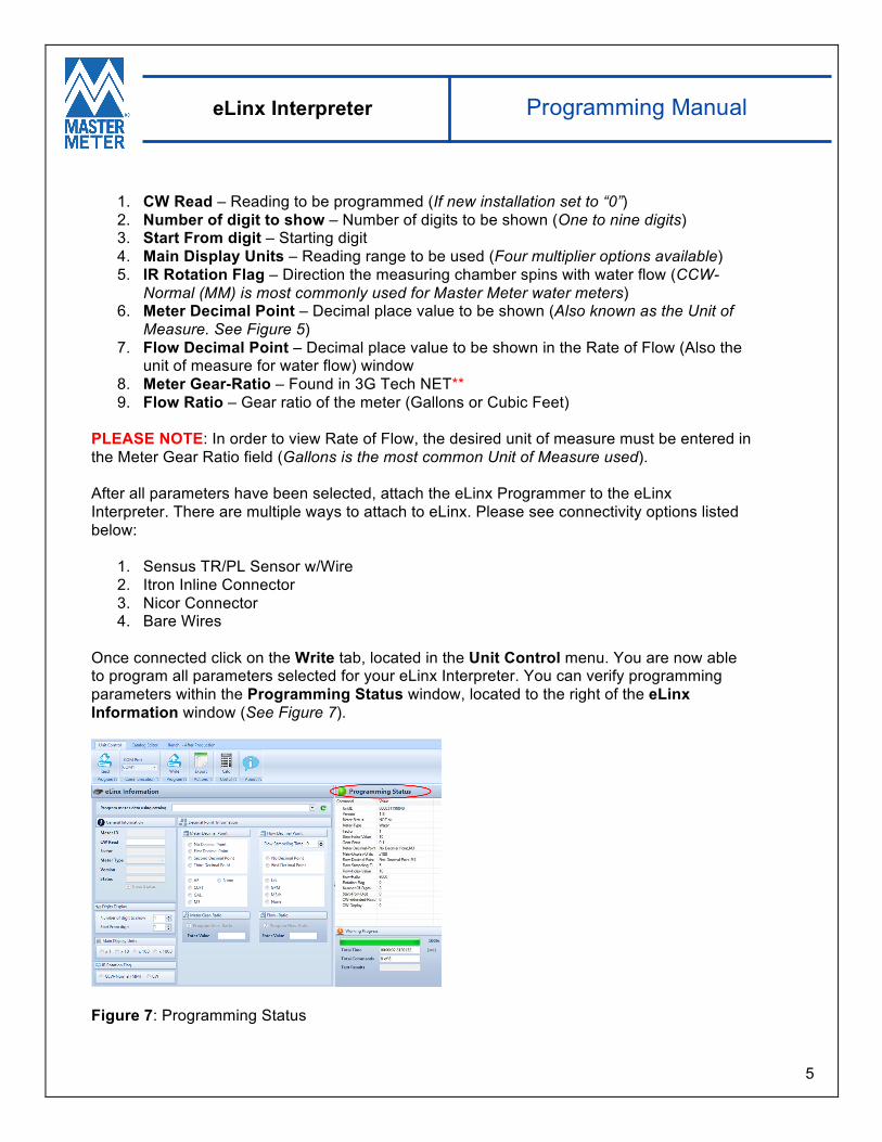
Once connected click on the Write tab, located in the Unit Control menu. You are now able to program all parameters selected for your eLinx Interpreter. You can verify programming parameters within the Programming Status window, located to the right of the eLinx Information window (See Figure 7).
Figure 7: Programming Status

6
eLinx Interpreter Programming Manual
**To locate the Meter Gear-Ratio for your eLinx Interpreter follow the steps below within 3G Tech NET:
1. Select the Interpreter box under the Select Unit Types menu. 2. Double-Click on Interpreter II Properties located in Set menu, directly to the right of
the Select Unit Types menu. 3. Select the correct Brand, Size (Diameter) and Model (Catalog) meter you are
installing. Once preferences have been selected the Gear Ratio will appear. 4. Enter this value within the Meter Gear-Ratio field of eLinx Tech to continue
programming your eLinx Interpreter.