Embed Size (px)
Citation preview
INSTRUCTION MANUAL
ELITE CLASSICWIRELESS ELECTRICITY MONITOR
*All values shown in this manual are only examples. Actual figures will vary depending on your consumption.
At the end of its serviceable life, this product should not be treated as household general waste. It should be handed over to the applicable collection point for the recycling of electrical equipment, or returned to the supplier for disposal.

CONTENTS INTRODUCTION
2
INTRODUCTIONSAFETYIN THE BOX
HARDWARE INSTALLATION Prior to Installation Mounting Individual or Multiple Circuits Monitor Installation Considerations Installing the CT Sensors
MONITOR SETUP Linking Transmitter and Monitor Setting the Time & Date Setup Instructions Dual Tariff Mode Energy Now Mode History Mode
FAQsTECHNICAL INFORMATIONINSTALLATION NOTESTECHNICAL NOTES FOR ELECTRICIAN
235
67910
111213151617
18191920
Energy metering and monitoring are at the heart of energy management, understanding when and where your energy is consumed is key to saving money.
The elite wireless electricity monitor shows the amount of energy that a household is consuming at the time the display is read. The display can also give the user a reading showing usage in financial terms. You can walk around the home with your monitor device, switching appliances on and off, to see the difference that each one makes. With a few small changes in your consumption behaviour the elite can help you reduce your energy costs.
Ask GeorgeIf you have any questions about using your efergy monitor or if you’d like further advice on monitoring electricity at home, please feel free to contact us, or visit the website for up to date information, downloads and frequently asked questions. We aim to answer all your emails within 48 hours
Email your questions to; [email protected]
Email your technical questions to; [email protected]
Efergy Customer Service:(+44) 1143272646
www.efergy.com for United Kingdom

IMPORTANT SAFETY INFORMATION
3 4
It is important that you take some simple precautions before using this product. Incorrect use or poor safety practices can result in injury or fatality. Whenever possible, turn off the main breaker, outside your home feeding power to your electric panel.
When installing the elite monitor you should find that everything is straight-forward. However, there are a number of important health and safety issues which you need to be aware of:
Mini CT sensor clip fits onto the internal live feed cable inside the electricity meter, which delivers the live supply to your home.
Do not touch any metallic connections during the installation of the mini CT sensor. Do not carry out this installation if under the influence of alcohol or drugs.
Remember the device is not intrusive and does not require rewiring; no wires or cables need to be cut, removed or modified to perform this installation. If you notice anything unusual about the electricity supply such as loose wires, exposed cabling, burn marks, holes in the insulating materials or damage to the electric wires in the service panel or where the mini CT sensor is to be attached, stop immediately and report the findings to your supply company.
efergy energy monitoring systems are considered plug and play devices that meet all regulatory requirements for installation in the United Kingdom.
Do not force or bend the cables at any point during installation. If you are worried or have any concerns about the installation, please contact a qualified electrician immediately.
•
•
•
•
•
•
•
•
•
The user does not need to remove the sensor throughout the working life of the unit. Battery changes are performed on the transmitter and on the display. There are no batteries to change in the sensor.
Even with the main breaker in the off position, the connection lugs where the main wires terminate at the main breaker may still be live with potentially lethal voltage. Stay clear of these connections during the installation of the mini CT sensor, see page 9.
The mini CT sensor itself is insulated so do not be concerned if it slides down the main wire to the breaker after being secured around the insulated wire. A plastic tie wrap (with 5cm of the tie not cut off) secured to the main wire under the desired location for the sensor may be used to keep the sensor from sliding down the wire.
Millions of these systems have been installed world wide without incident but please follow safe work practices as outlined during the installation.

5 6
HARDWARE INSTALLATIONIN THE BOX
Your elite pack contains the following elements:
1 x mini CT Sensor1 x Transmitter 1 x elite Wireless Energy Monitor
You will need to attach the sensor to the live feed cable which connects the meter to the monitor. Any power you use in your home will pass through this cable. The clip on sensor relays the amount of current being drawn in the home to the transmitter. From there it is sent wirelessly to the energy monitor, which shows how much power is being consumed.
It also includes:
1 x Instruction manual for the monitor1 x Quick Start Guide
Wireless Energy Monitor
Mini CT Sensor Transmitter
PRIOR TO INSTALLATION
The efergy elite is installed by clipping the mini CT sensor around the feed wire of your electric panel. In the United Kingdom the standard residential voltage is 240V.
Note - For a 240V panel (typical residential electric panel) power is measured using one mini CT sensor. For different voltages, please change during the Monitor Setup stage (see page 13).
Installation for Three Phase PanelsThe elite is installed by clipping the mini CT sensors around the feed wire of your electric panel. In the case of a commercial or industrial three phase panel or service, you must use three mini CT sensors to measure all three phases. Simply order an additional two mini CT sensors from your dealer. Identify the three power wires providing service to your electric panel. Open and place one sensor around each of the three main feed wires.
Installing Transmitter for Three PhasePlug the three mini CT sensor cables into the transmitter. Mount the transmitter on the wall next to the electric panel. This will make it easier to replace the batteries. Readings for a three phase system may not be accurate depending on connection and loading system.
WE RECOMMEND THAT THE EFERGY MONITOR IS INSTALLED BY A LICENSED ELECTRICIAN
HARDWARE INSTALLATION
87
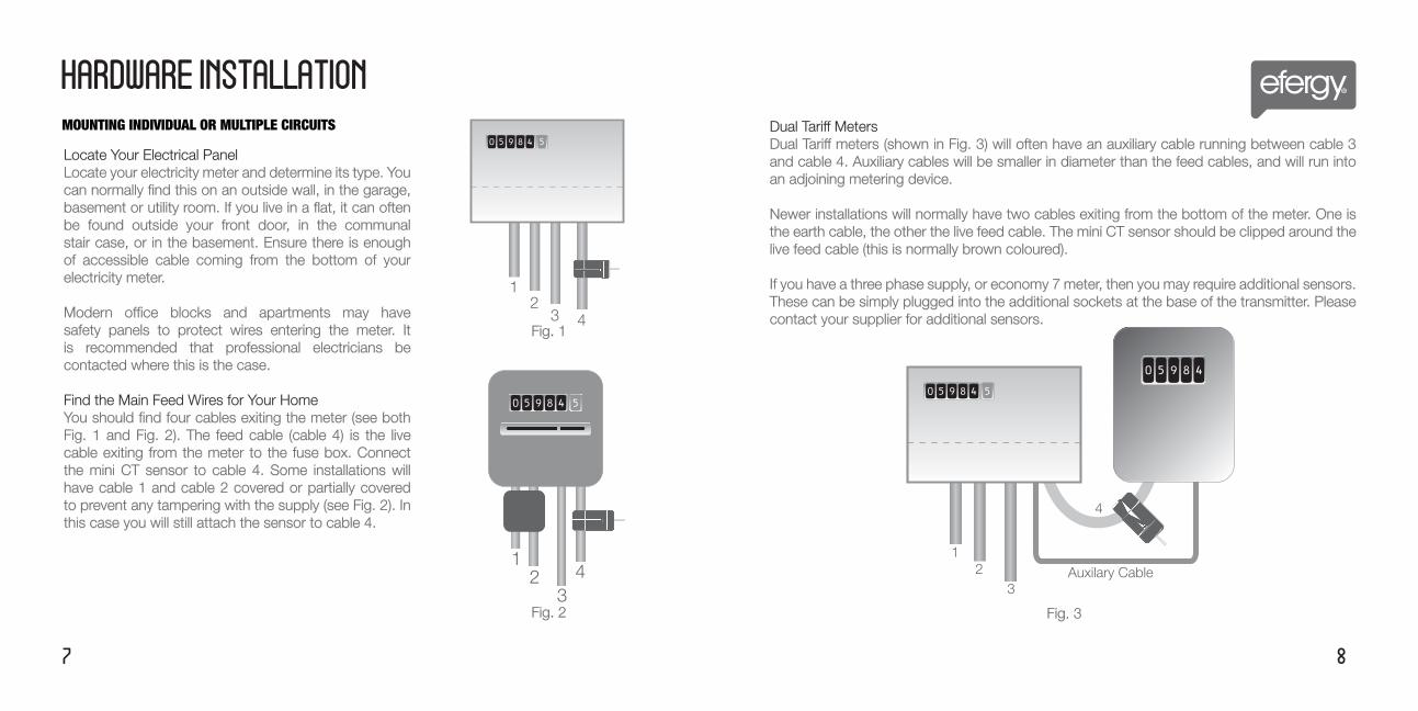
Locate Your Electrical Panel Locate your electricity meter and determine its type. You can normally find this on an outside wall, in the garage, basement or utility room. If you live in a flat, it can often be found outside your front door, in the communal stair case, or in the basement. Ensure there is enough of accessible cable coming from the bottom of your electricity meter.
Modern office blocks and apartments may have safety panels to protect wires entering the meter. It is recommended that professional electricians be contacted where this is the case.
Find the Main Feed Wires for Your HomeYou should find four cables exiting the meter (see both Fig. 1 and Fig. 2). The feed cable (cable 4) is the live cable exiting from the meter to the fuse box. Connect the mini CT sensor to cable 4. Some installations will have cable 1 and cable 2 covered or partially covered to prevent any tampering with the supply (see Fig. 2). In this case you will still attach the sensor to cable 4.
Dual Tariff MetersDual Tariff meters (shown in Fig. 3) will often have an auxiliary cable running between cable 3 and cable 4. Auxiliary cables will be smaller in diameter than the feed cables, and will run into an adjoining metering device.
Newer installations will normally have two cables exiting from the bottom of the meter. One is the earth cable, the other the live feed cable. The mini CT sensor should be clipped around the live feed cable (this is normally brown coloured).
If you have a three phase supply, or economy 7 meter, then you may require additional sensors. These can be simply plugged into the additional sockets at the base of the transmitter. Please contact your supplier for additional sensors.
Auxilary Cable1
23
4
12
3 4Fig. 1
Fig. 3
12
34
Fig. 2
MOUNTING INDIVIDUAL OR MULTIPLE CIRCUITS
HARDWARE INSTALLATION
10 9
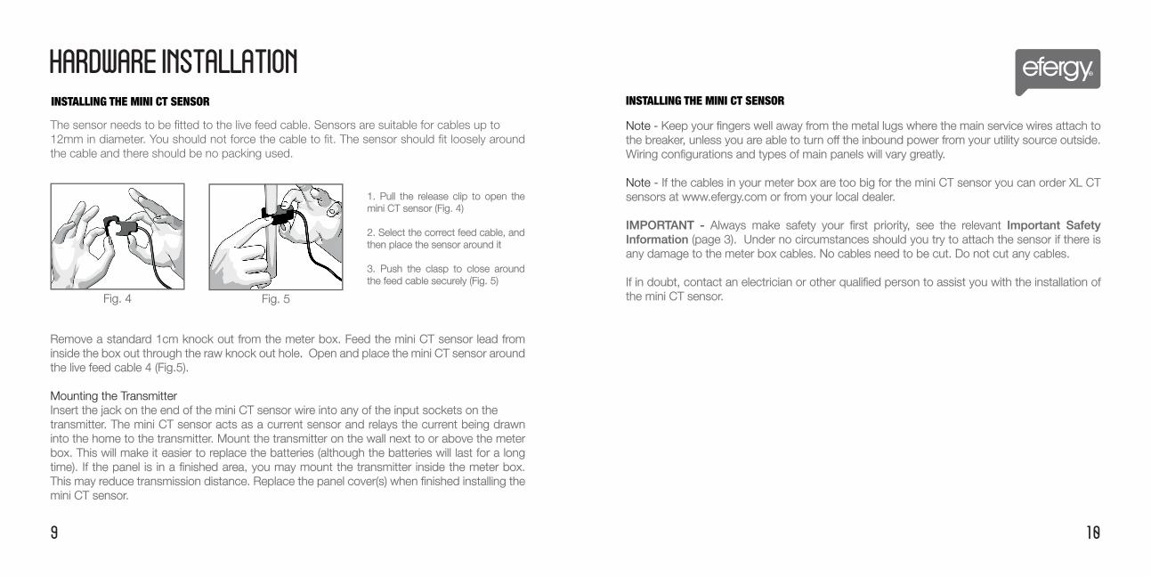
The sensor needs to be fitted to the live feed cable. Sensors are suitable for cables up to 12mm in diameter. You should not force the cable to fit. The sensor should fit loosely around the cable and there should be no packing used.
Remove a standard 1cm knock out from the meter box. Feed the mini CT sensor lead from inside the box out through the raw knock out hole. Open and place the mini CT sensor around the live feed cable 4 (Fig.5).
Mounting the TransmitterInsert the jack on the end of the mini CT sensor wire into any of the input sockets on thetransmitter. The mini CT sensor acts as a current sensor and relays the current being drawn into the home to the transmitter. Mount the transmitter on the wall next to or above the meter box. This will make it easier to replace the batteries (although the batteries will last for a long time). If the panel is in a finished area, you may mount the transmitter inside the meter box. This may reduce transmission distance. Replace the panel cover(s) when finished installing the mini CT sensor.
INSTALLING THE MINI CT SENSORINSTALLING THE MINI CT SENSOR
Fig. 4 Fig. 5
1. Pull the release clip to open the mini CT sensor (Fig. 4)
2. Select the correct feed cable, and then place the sensor around it
3. Push the clasp to close around the feed cable securely (Fig. 5)
Note - Keep your fingers well away from the metal lugs where the main service wires attach to the breaker, unless you are able to turn off the inbound power from your utility source outside. Wiring configurations and types of main panels will vary greatly.
Note - If the cables in your meter box are too big for the mini CT sensor you can order XL CT sensors at www.efergy.com or from your local dealer.
IMPORTANT - Always make safety your first priority, see the relevant Important Safety Information (page 3). Under no circumstances should you try to attach the sensor if there is any damage to the meter box cables. No cables need to be cut. Do not cut any cables.
If in doubt, contact an electrician or other qualified person to assist you with the installation of the mini CT sensor.
11 12
MONITOR SETUP
LINKING TRANSMITTER AND MONITOR
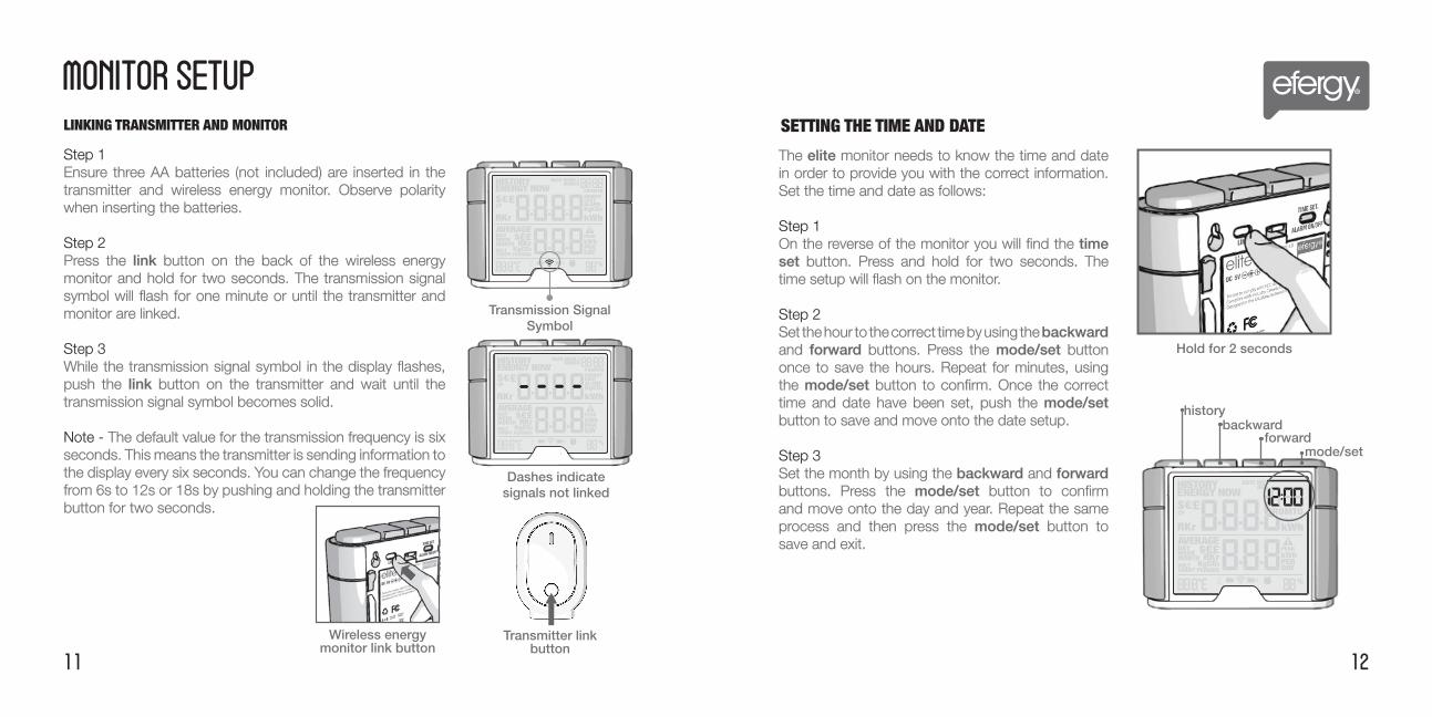
Transmission Signal Symbol
Dashes indicate signals not linked
Transmitter link button
Step 1 Ensure three AA batteries (not included) are inserted in the transmitter and wireless energy monitor. Observe polarity when inserting the batteries.
Step 2Press the link button on the back of the wireless energy monitor and hold for two seconds. The transmission signal symbol will flash for one minute or until the transmitter and monitor are linked.
Step 3While the transmission signal symbol in the display flashes, push the link button on the transmitter and wait until the transmission signal symbol becomes solid.
Note - The default value for the transmission frequency is six seconds. This means the transmitter is sending information to the display every six seconds. You can change the frequency from 6s to 12s or 18s by pushing and holding the transmitter button for two seconds.
Wireless energy monitor link button
SETTING THE TIME AND DATE
Hold for 2 seconds
The elite monitor needs to know the time and date in order to provide you with the correct information. Set the time and date as follows:
Step 1 On the reverse of the monitor you will find the time set button. Press and hold for two seconds. The time setup will flash on the monitor.
Step 2Set the hour to the correct time by using the backward and forward buttons. Press the mode/set button once to save the hours. Repeat for minutes, using the mode/set button to confirm. Once the correct time and date have been set, push the mode/set button to save and move onto the date setup.
Step 3Set the month by using the backward and forward buttons. Press the mode/set button to confirm and move onto the day and year. Repeat the same process and then press the mode/set button to save and exit.
historybackward
forwardmode/set
14 13
MONITOR SETUP
SETUP INSTRUCTIONS
Note - Throughout the setup process, push history button at any time, your settings will be saved & you will exit the function setting mode.
Note - Twenty seconds of inactivity in setting mode will return the monitor to normal display mode without saving changes.
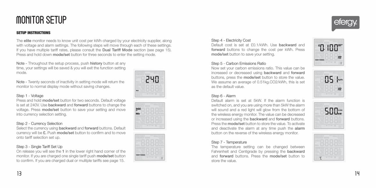
Step 1 - VoltagePress and hold mode/set button for two seconds. Default voltage is set at 240V. Use backward and forward buttons to change the voltage. Press mode/set button to save your setting and move into currency selection setting.
Step 2 - Currency SelectionSelect the currency using backward and forward buttons. Default currency will be £. Push mode/set button to confirm and to move onto tariff selection set up.
Step 3 - Single Tariff Set UpOn release you will see the 1 in the lower right hand corner of the monitor. If you are charged one single tariff push mode/set button to confirm. If you are charged dual or mulitple tariffs see page 15.
The elite monitor needs to know unit cost per kWh charged by your electricity supplier, along with voltage and alarm settings. The following steps will move through each of these settings. If you have multiple tariff rates, please consult the Dual Tariff Mode section (see page 15). Press and hold down mode/set button for three seconds to enter the setting mode.
Step 4 - Electricity CostDefault cost is set at £0.1/kWh. Use backward and forward buttons to change the cost per kWh. Press mode/set button to save your setting.
Step 5 - Carbon Emissions RatioNow set your carbon emissions ratio. This value can be increased or decreased using backward and forward buttons, press the mode/set button to store the value. We assume an average of 0.51kg.CO2/kWh, this is set as the default value.
Step 6 - AlarmDefault alarm is set at 5kW. If the alarm function is switched on, and you are using more than 5kW the alarm will sound and a red light will glow from the bottom of the wireless energy monitor. The value can be decreased or increased using the backward and forward buttons. Press the mode/set button to store the value. To activate and deactivate the alarm at any time push the alarm button on the reverse of the wireless energy monitor.
Step 7 - TemperatureThe temperature setting can be changed between Fahrenheit and Centigrade by pressing the backward and forward buttons. Press the mode/set button to store the value.
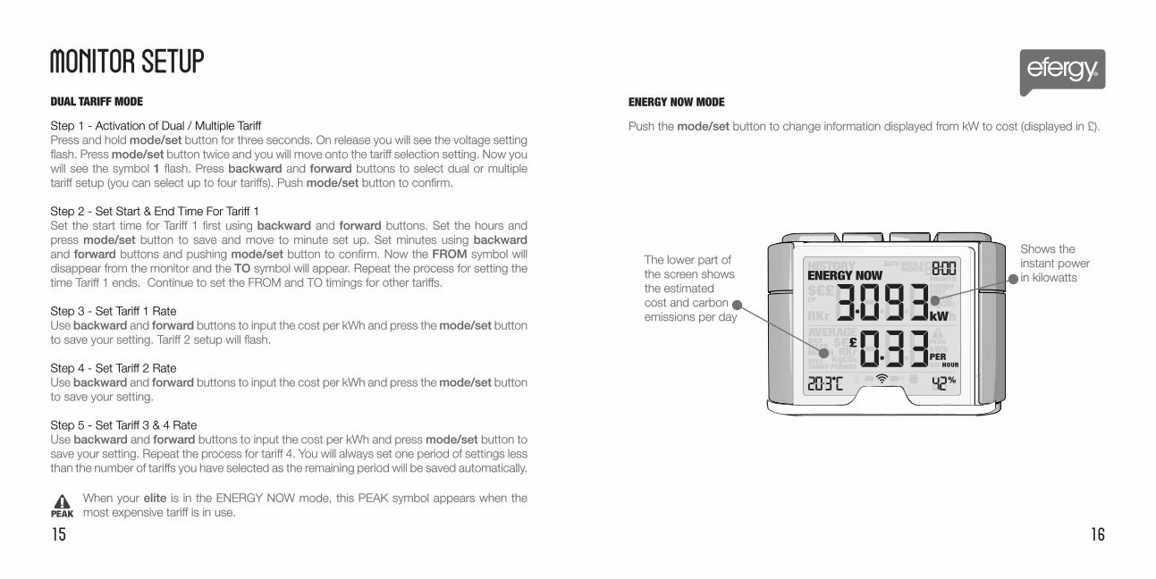
DUAL TARIFF MODE
Step 1 - Activation of Dual / Multiple TariffPress and hold mode/set button for three seconds. On release you will see the voltage setting flash. Press mode/set button twice and you will move onto the tariff selection setting. Now you will see the symbol 1 flash. Press backward and forward buttons to select dual or multiple tariff setup (you can select up to four tariffs). Push mode/set button to confirm.
Step 2 - Set Start & End Time For Tariff 1Set the start time for Tariff 1 first using backward and forward buttons. Set the hours and press mode/set button to save and move to minute set up. Set minutes using backward and forward buttons and pushing mode/set button to confirm. Now the FROM symbol will disappear from the monitor and the TO symbol will appear. Repeat the process for setting the time Tariff 1 ends. Continue to set the FROM and TO timings for other tariffs.
Step 3 - Set Tariff 1 RateUse backward and forward buttons to input the cost per kWh and press the mode/set button to save your setting. Tariff 2 setup will flash.
Step 4 - Set Tariff 2 RateUse backward and forward buttons to input the cost per kWh and press the mode/set button to save your setting.
Step 5 - Set Tariff 3 & 4 RateUse backward and forward buttons to input the cost per kWh and press mode/set button to save your setting. Repeat the process for tariff 4. You will always set one period of settings less than the number of tariffs you have selected as the remaining period will be saved automatically.
15 16
MONITOR SETUP
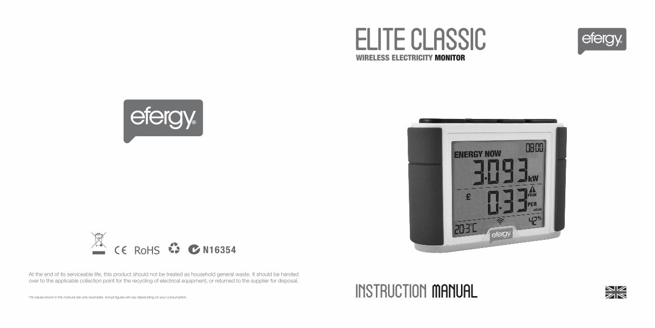
The lower part of the screen shows the estimated cost and carbon emissions per day
ENERGY NOW MODE
Push the mode/set button to change information displayed from kW to cost (displayed in £).
Shows the instant power in kilowatts
When your elite is in the ENERGY NOW mode, this PEAK symbol appears when the most expensive tariff is in use.
17 18
MONITOR SETUP FAQS
If I remove the batteries will I lose the information on the monitor?The monitor has an internal memory, so if you need to change or remove the batteries and the information stored on it will not be lost.
How do I reset the monitor (clear the stored data and start again)?Press and hold the mode/set and history buttons simultaneously for two seconds.
How far does the device transmit?The transmitter works up to around 70m within the home. The 433MHz range is well suited for in-home use. This can cover three floors and is also ideal for buildings where electricity meters are situated outside.
I have dashes (- - - -) showing on the monitor. What does this mean?Move the monitor closer to the transmitter and press the link button. If the dashes remain on the monitor this would indicate that the transmitter and receiver are not communicating. Please contact our customer services to help solve the problem.
The backlight appears to work sometimes and then not others. Is it broken?No. The backlight is on a timer to save battery life. The monitor should work at darker periods during the day when any buttons are pressed. The LED backlight will be activated from 18:00 to 6:00 hours.
For more information about the elite go to www.efergy.comContact efergy customer service phoneline on (+44) 7851 233471
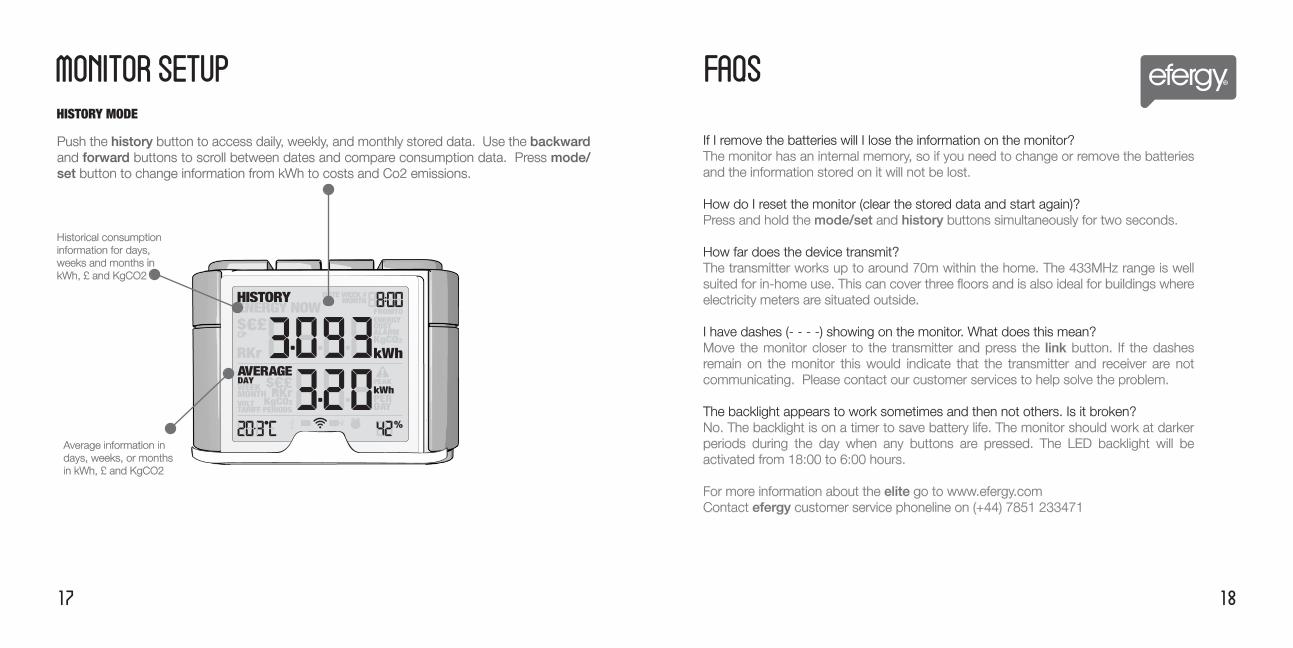
Historical consumption information for days, weeks and months in kWh, £ and KgCO2
Push the history button to access daily, weekly, and monthly stored data. Use the backward and forward buttons to scroll between dates and compare consumption data. Press mode/set button to change information from kWh to costs and Co2 emissions.
HISTORY MODE
Average information in days, weeks, or months in kWh, £ and KgCO2
INSTALLATION NOTES
TECHNICAL NOTES FOR ELECTRICIAN
20 19
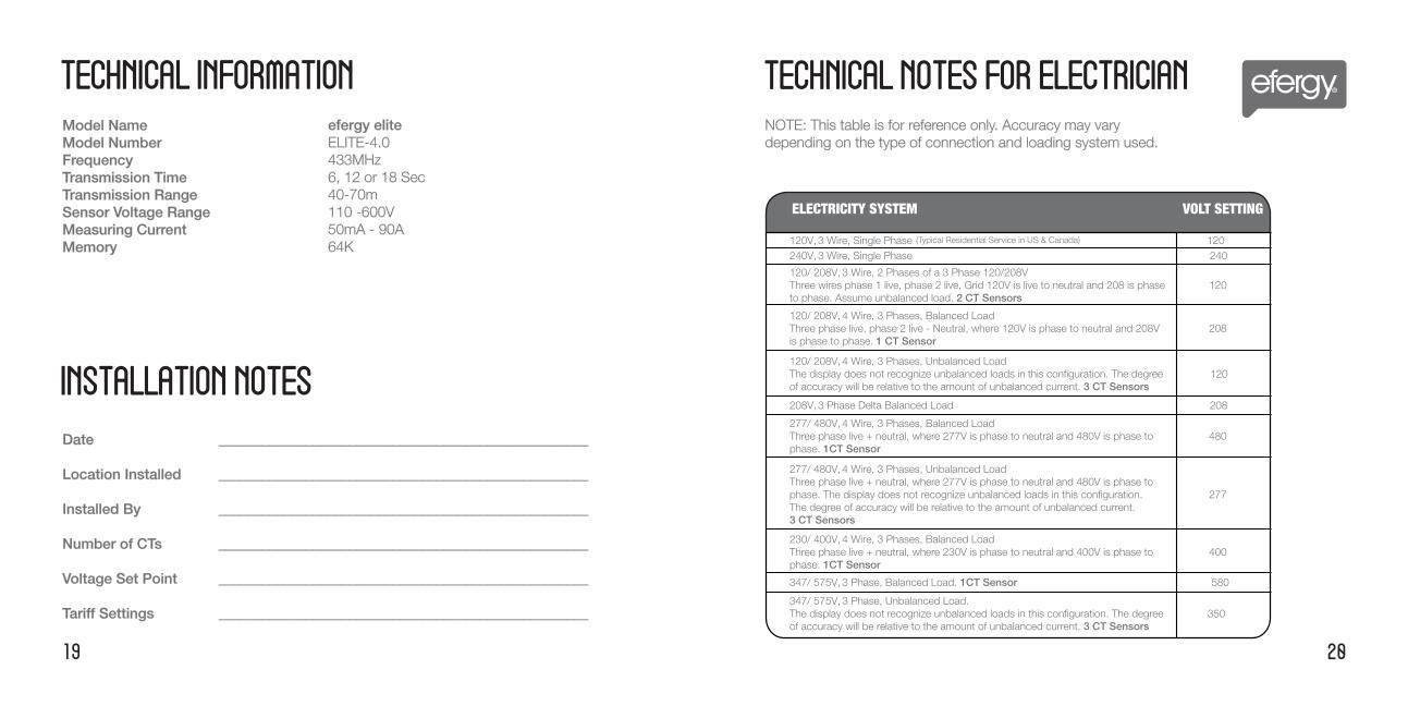
TECHNICAL INFORMATION
Model Name Model NumberFrequency Transmission Time Transmission Range Sensor Voltage Range Measuring CurrentMemory
efergy elite ELITE-4.0433MHz6, 12 or 18 Sec40-70m110 -600V50mA - 90A 64K
NOTE: This table is for reference only. Accuracy may vary depending on the type of connection and loading system used.
120V, 3 Wire, Single Phase 120240V, 3 Wire, Single Phase 240
120/ 208V, 3 Wire, 2 Phases of a 3 Phase 120/208V Three wires phase 1 live, phase 2 live, Grid 120V is live to neutral and 208 is phase 120to phase. Assume unbalanced load. 2 CT Sensors
120/ 208V, 4 Wire, 3 Phases, Balanced Load Three phase live, phase 2 live - Neutral, where 120V is phase to neutral and 208V 208is phase to phase. 1 CT Sensor
120/ 208V, 4 Wire, 3 Phases, Unbalanced Load The display does not recognize unbalanced loads in this configuration. The degree 120of accuracy will be relative to the amount of unbalanced current. 3 CT Sensors
208V, 3 Phase Delta Balanced Load 208
277/ 480V, 4 Wire, 3 Phases, Balanced Load Three phase live + neutral, where 277V is phase to neutral and 480V is phase to 480phase. 1CT Sensor
277/ 480V, 4 Wire, 3 Phases, Unbalanced Load Three phase live + neutral, where 277V is phase to neutral and 480V is phase to phase. The display does not recognize unbalanced loads in this configuration. 277The degree of accuracy will be relative to the amount of unbalanced current. 3 CT Sensors
230/ 400V, 4 Wire, 3 Phases, Balanced Load Three phase live + neutral, where 230V is phase to neutral and 400V is phase to 400phase. 1CT Sensor
347/ 575V, 3 Phase, Balanced Load. 1CT Sensor 580
347/ 575V, 3 Phase, Unbalanced Load. The display does not recognize unbalanced loads in this configuration. The degree 350of accuracy will be relative to the amount of unbalanced current. 3 CT Sensors
ELECTRICITY SYSTEM VOLT SETTING
Date ___________________________________________________
Location Installed ___________________________________________________
Installed By ___________________________________________________
Number of CTs ___________________________________________________
Voltage Set Point ___________________________________________________
Tariff Settings ___________________________________________________
(Typical Residential Service in US & Canada)