Embed Size (px)
Citation preview
Winning Foundations Start with EMI
APPL
ICAT
ION
GUID
EELITE FORMINGSYSTEMS
EMI Construction Products | 800-603-9965 | fax 616-392-7464 | www.emisupplies.com
2
TABLE OF CONTENTS
2 Safety Information 3 EMI Elite Forming Systems 4 Panels and Fillers 5 Connecting Panels to Each Other 6 Setting Panels on Footings 6 Where to Start Panel Placement 7 Using Fillers Between Panels 8 Securing Panels with Walers 9 Form Alignment 10 Strongbacks for Vertical Strength 11 Scaffold Brackets 12 Forming Footings 13 Adjustments for Panel Placement
14 Corners 15 Intersections 16 Form Extensions 17 Pilaster Forms 18 Pilaster Brace 19 Capping the Wall Pour 20 Stacking Forms 20 Second Lift Forming 21 Special Purpose Ties 23 Curved Walls 25 Wire Tie Gang Forming 26 Stripping Forms
n Inspect all equipment before using. Never use equipment which appears damaged.n Be sure that all ties of the right length are used for a specific wall thickness. Intermixed
tie lengths will allow for excessive pressure and possible tie failure.n Never bend a tie to work around rebar. This can fracture the tie at the breakback point
and reduce load capacity.n Never beat on the end of a tie to force it through a tie slot. This could damage the
breakback or loop weld and cause a failure. Replace any ties that are bent or compro-mised before pouring concrete.
n Walers must be used in order to hold forms in accurate alignment.n Install and position form scaffold brackets or other equivalent means to permit worker
access to areas requiring setting, pouring and stripping operations.n Brace one side of forms securely against wind loads, impact of concrete placement and
live load of personnel working on forms. Normal bracing is 6' to 10' on center horizon-tally and each vertical lift of forms.
n Before placing concrete, responsible person(s) should check both sides of the wall to make sure that all ties are in place and properly connected. Assure that all wedgebolts are maintained tight and secure in proper positions.
n Standard practices for placing concrete must be followed. Concrete should not be dropped without the use of an elephant trunk. Vibrating should be limited to 4' below top of concrete surface, and not used to move the concrete laterally.
n Protective devices such as gloves, safety glasses and steel toe shoes should be worn during formwork.
SAFETY INFORMATION
This illustration booklet is designed to show you how to handset residential or light com-mercial foundation forms, using EMI Elite Forming Panels, hardware and accessories. EMI Elite components and accessories illustrated in this Application Guide have been designed with safety and performance in mind to help achieve a productive forming operation. All construction personnel should thoroughly familiarize themselves and comply with the appli-cable industry standards and safe practices established by the American Concrete Institute, American National Standards Institute, The Occupational Safety and Health Administration, and the Scaffolding, Shoring and Forming Institute. Tie spacings shown are for illustration purposes only; proper spacing must be determined for the individual job. Tie capacities are detailed on page 21. The maximum allowable pour pressure for the system is 1000 psf.
NOTE: EMI Construction Products recommends the use of all safety equipment and apparel such as gloves, safety shoes, safety glasses and hard hats when erecting or dismantling of Elite Forms.
EMI Construction Products | 800-603-9965 | fax 616-392-7464 | www.emisupplies.com
3
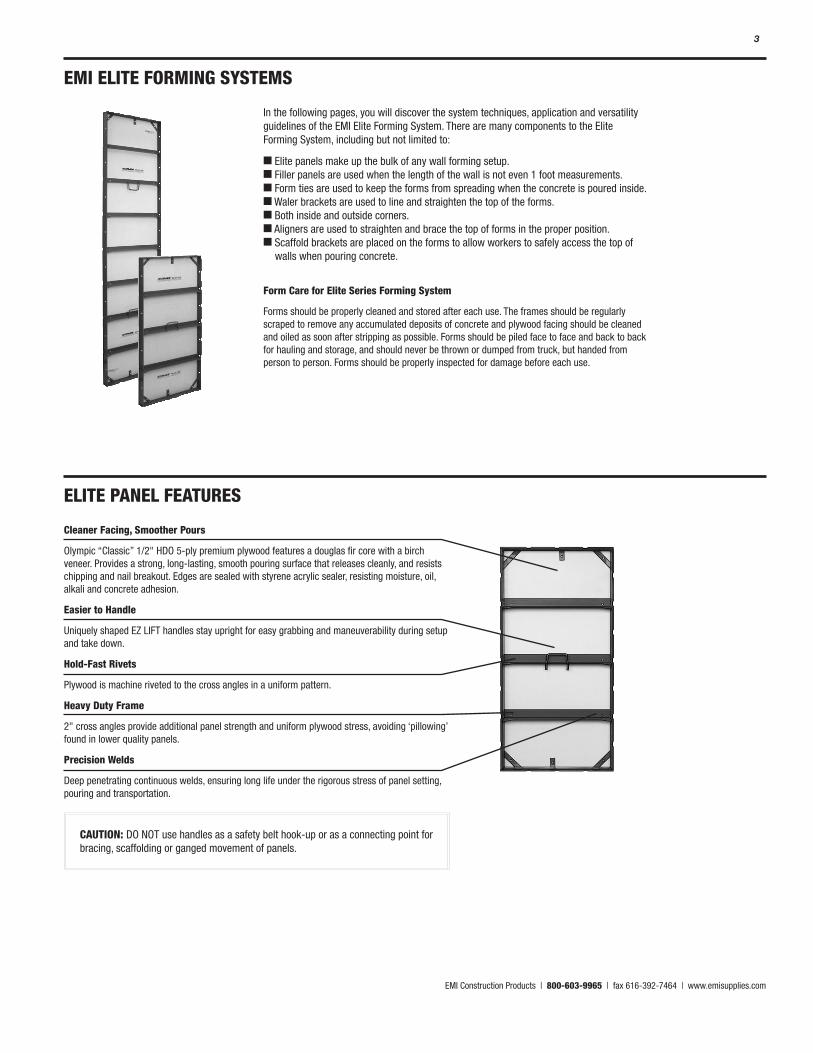
EMI ELITE FORMING SYSTEMS
Cleaner Facing, Smoother Pours
Olympic “Classic” 1/2" HDO 5-ply premium plywood features a douglas fir core with a birch veneer. Provides a strong, long-lasting, smooth pouring surface that releases cleanly, and resists chipping and nail breakout. Edges are sealed with styrene acrylic sealer, resisting moisture, oil, alkali and concrete adhesion.
Easier to Handle
Uniquely shaped EZ LIFT handles stay upright for easy grabbing and maneuverability during setup and take down.
Hold-Fast Rivets
Plywood is machine riveted to the cross angles in a uniform pattern.
Heavy Duty Frame
2" cross angles provide additional panel strength and uniform plywood stress, avoiding ‘pillowing’ found in lower quality panels.
Precision Welds
Deep penetrating continuous welds, ensuring long life under the rigorous stress of panel setting, pouring and transportation.
In the following pages, you will discover the system techniques, application and versatility guidelines of the EMI Elite Forming System. There are many components to the Elite Forming System, including but not limited to:
n Elite panels make up the bulk of any wall forming setup. n Filler panels are used when the length of the wall is not even 1 foot measurements. n Form ties are used to keep the forms from spreading when the concrete is poured inside. n Waler brackets are used to line and straighten the top of the forms. n Both inside and outside corners. n Aligners are used to straighten and brace the top of forms in the proper position. n Scaffold brackets are placed on the forms to allow workers to safely access the top of walls when pouring concrete.
Form Care for Elite Series Forming System
Forms should be properly cleaned and stored after each use. The frames should be regularly scraped to remove any accumulated deposits of concrete and plywood facing should be cleaned and oiled as soon after stripping as possible. Forms should be piled face to face and back to back for hauling and storage, and should never be thrown or dumped from truck, but handed from person to person. Forms should be properly inspected for damage before each use.
ELITE PANEL FEATURES
CAUTION: DO NOT use handles as a safety belt hook-up or as a connecting point for bracing, scaffolding or ganged movement of panels.
EMI Construction Products | 800-603-9965 | fax 616-392-7464 | www.emisupplies.com
4
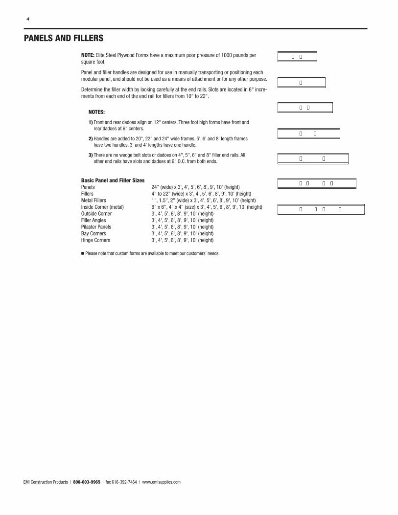
NOTE: Elite Steel Plywood Forms have a maximum poor pressure of 1000 pounds per square foot.
Panel and filler handles are designed for use in manually transporting or positioning each modular panel, and should not be used as a means of attachment or for any other purpose.
Determine the filler width by looking carefully at the end rails. Slots are located in 6" incre-ments from each end of the end rail for fillers from 10" to 22".
Basic Panel and Filler Sizes Panels 24" (wide) x 3', 4', 5', 6', 8', 9', 10' (height) Fillers 4" to 22" (wide) x 3', 4', 5', 6', 8', 9', 10' (height) Metal Fillers 1", 1.5", 2" (wide) x 3', 4', 5', 6', 8', 9', 10' (height) Inside Corner (metal) 6" x 6", 4" x 4" (size) x 3', 4', 5', 6', 8', 9', 10' (height) Outside Corner 3', 4', 5', 6', 8', 9', 10' (height) Filler Angles 3', 4', 5', 6', 8', 9', 10' (height) Pilaster Panels 3', 4', 5', 6', 8', 9', 10' (height) Bay Corners 3', 4', 5', 6', 8', 9', 10' (height) Hinge Corners 3', 4', 5', 6', 8', 9', 10' (height)
n Please note that custom forms are available to meet our customers’ needs.
NOTES:
1) Front and rear dadoes align on 12" centers. Three foot high forms have front and rear dadoes at 6" centers.
2) Handles are added to 20", 22" and 24" wide frames. 5', 6' and 8' length frames have two handles. 3' and 4' lengths have one handle.
3) There are no wedge bolt slots or dadoes on 4", 5", 6" and 8" filler end rails. All other end rails have slots and dadoes at 6" O.C. from both ends.
PANELS AND FILLERS
EMI Construction Products | 800-603-9965 | fax 616-392-7464 | www.emisupplies.com
5
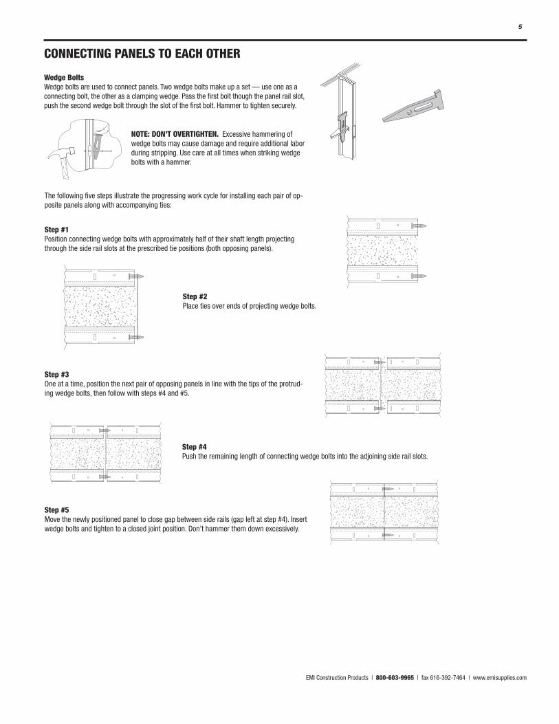
Wedge Bolts Wedge bolts are used to connect panels. Two wedge bolts make up a set — use one as a connecting bolt, the other as a clamping wedge. Pass the first bolt though the panel rail slot, push the second wedge bolt through the slot of the first bolt. Hammer to tighten securely.
CONNECTING PANELS TO EACH OTHER
Step #1 Position connecting wedge bolts with approximately half of their shaft length projecting through the side rail slots at the prescribed tie positions (both opposing panels).
Step #2 Place ties over ends of projecting wedge bolts.
Step #3 One at a time, position the next pair of opposing panels in line with the tips of the protrud-ing wedge bolts, then follow with steps #4 and #5.
Step #4 Push the remaining length of connecting wedge bolts into the adjoining side rail slots.
Step #5 Move the newly positioned panel to close gap between side rails (gap left at step #4). Insert wedge bolts and tighten to a closed joint position. Don’t hammer them down excessively.
The following five steps illustrate the progressing work cycle for installing each pair of op-posite panels along with accompanying ties:
NOTE: DON’T OVERTIGHTEN. Excessive hammering of wedge bolts may cause damage and require additional labor during stripping. Use care at all times when striking wedge bolts with a hammer.
EMI Construction Products | 800-603-9965 | fax 616-392-7464 | www.emisupplies.com
6
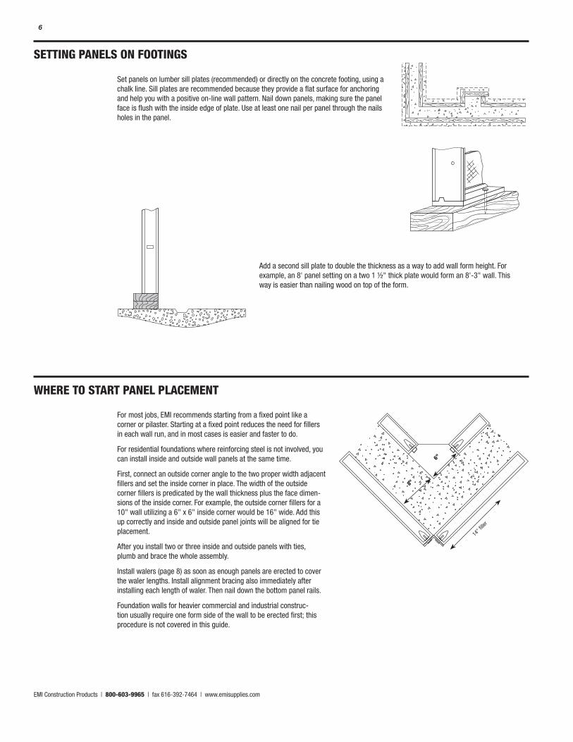
Set panels on lumber sill plates (recommended) or directly on the concrete footing, using a chalk line. Sill plates are recommended because they provide a flat surface for anchoring and help you with a positive on-line wall pattern. Nail down panels, making sure the panel face is flush with the inside edge of plate. Use at least one nail per panel through the nails holes in the panel.
Add a second sill plate to double the thickness as a way to add wall form height. For example, an 8' panel setting on a two 1 ½" thick plate would form an 8'-3" wall. This way is easier than nailing wood on top of the form.
SETTING PANELS ON FOOTINGS
WHERE TO START PANEL PLACEMENT
For most jobs, EMI recommends starting from a fixed point like a corner or pilaster. Starting at a fixed point reduces the need for fillers in each wall run, and in most cases is easier and faster to do.
For residential foundations where reinforcing steel is not involved, you can install inside and outside wall panels at the same time.
First, connect an outside corner angle to the two proper width adjacent fillers and set the inside corner in place. The width of the outside corner fillers is predicated by the wall thickness plus the face dimen-sions of the inside corner. For example, the outside corner fillers for a 10" wall utilizing a 6" x 6" inside corner would be 16" wide. Add this up correctly and inside and outside panel joints will be aligned for tie placement.
After you install two or three inside and outside panels with ties, plumb and brace the whole assembly.
Install walers (page 8) as soon as enough panels are erected to cover the waler lengths. Install alignment bracing also immediately after installing each length of waler. Then nail down the bottom panel rails.
Foundation walls for heavier commercial and industrial construc-tion usually require one form side of the wall to be erected first; this procedure is not covered in this guide.
8"
6"
14" fi
ller
EMI Construction Products | 800-603-9965 | fax 616-392-7464 | www.emisupplies.com
7
USING FILLERS BETWEEN PANELS
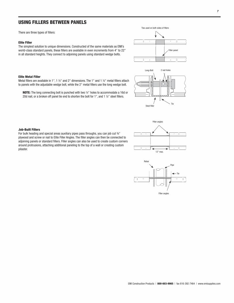
There are three types of fillers:
Elite Filler The simplest solution to unique dimensions. Constructed of the same materials as EMI’s world-class standard panels, these fillers are available in even increments from 4" to 22" in all standard heights. They connect to adjoining panels using standard wedge bolts.
Elite Metal Filler Metal fillers are available in 1", 1 ½" and 2" dimensions. The 1" and 1 ½" metal fillers attach to panels with the adjustable wedge bolt, while the 2" metal fillers use the long wedge bolt.
Job-Built Fillers For bulk heading and special areas auxiliary pipes pass throughs, you can job cut ¾" plywood and screw or nail to Elite Filler Angles. The filler angles can then be connected to adjoining panels or standard fillers. Filler angles can also be used to create custom corners around protrusions, attaching additional paneling to the top of a wall or creating custom pilaster.
NOTE: The long connecting bolt is punched with two ¼" holes to accommodate a 16d or 20d nail, or a broken off panel tie end to shorten the bolt for 1", and 1 ½" steel fillers.
Ties used on both sides of fillers
Filler panel
Long-Bolt 2 nail holes
TieSteel filler
Filler angles
12" max.
Rebar
Pipe
Tie
Filler angles
EMI Construction Products | 800-603-9965 | fax 616-392-7464 | www.emisupplies.com
8
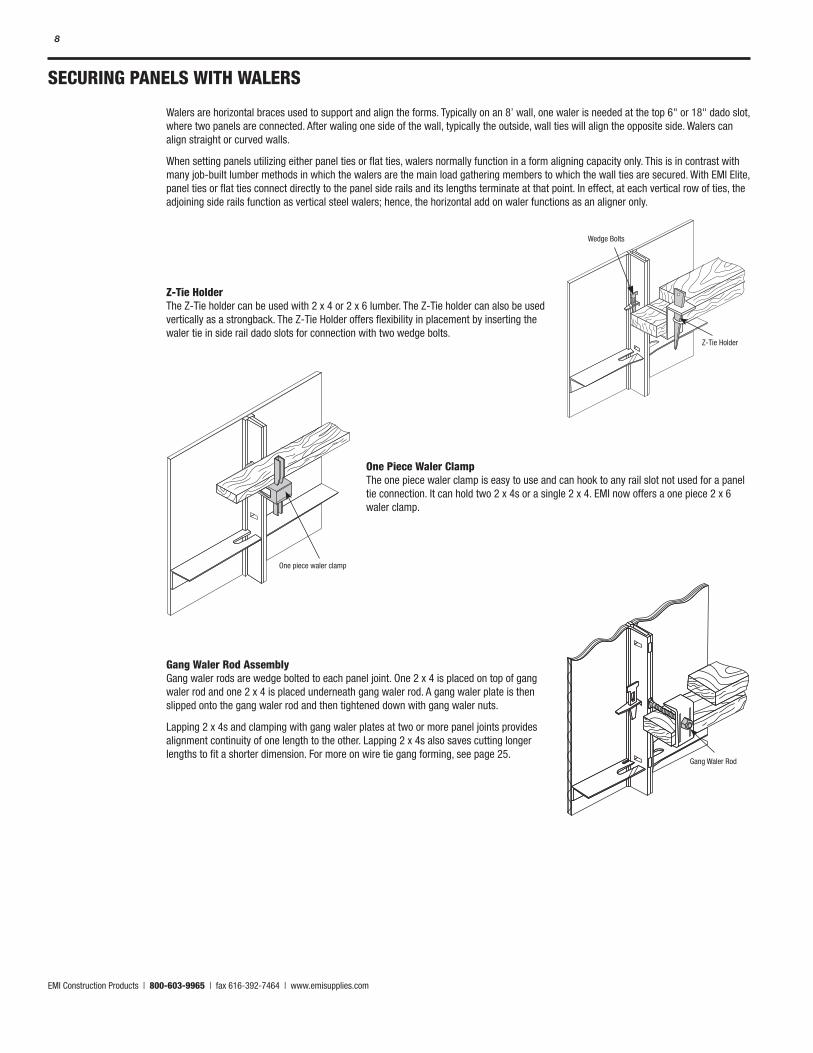
Gang Waler Rod Assembly Gang waler rods are wedge bolted to each panel joint. One 2 x 4 is placed on top of gang waler rod and one 2 x 4 is placed underneath gang waler rod. A gang waler plate is then slipped onto the gang waler rod and then tightened down with gang waler nuts.
Lapping 2 x 4s and clamping with gang waler plates at two or more panel joints provides alignment continuity of one length to the other. Lapping 2 x 4s also saves cutting longer lengths to fit a shorter dimension. For more on wire tie gang forming, see page 25.
SECURING PANELS WITH WALERS
Walers are horizontal braces used to support and align the forms. Typically on an 8’ wall, one waler is needed at the top 6" or 18" dado slot, where two panels are connected. After waling one side of the wall, typically the outside, wall ties will align the opposite side. Walers can align straight or curved walls.
When setting panels utilizing either panel ties or flat ties, walers normally function in a form aligning capacity only. This is in contrast with many job-built lumber methods in which the walers are the main load gathering members to which the wall ties are secured. With EMI Elite, panel ties or flat ties connect directly to the panel side rails and its lengths terminate at that point. In effect, at each vertical row of ties, the adjoining side rails function as vertical steel walers; hence, the horizontal add on waler functions as an aligner only.
Wedge Bolts
Z-Tie Holder
One piece waler clamp
Z-Tie Holder The Z-Tie holder can be used with 2 x 4 or 2 x 6 lumber. The Z-Tie holder can also be used vertically as a strongback. The Z-Tie Holder offers flexibility in placement by inserting the waler tie in side rail dado slots for connection with two wedge bolts.
One Piece Waler Clamp The one piece waler clamp is easy to use and can hook to any rail slot not used for a panel tie connection. It can hold two 2 x 4s or a single 2 x 4. EMI now offers a one piece 2 x 6 waler clamp.
Gang Waler Rod
EMI Construction Products | 800-603-9965 | fax 616-392-7464 | www.emisupplies.com
9
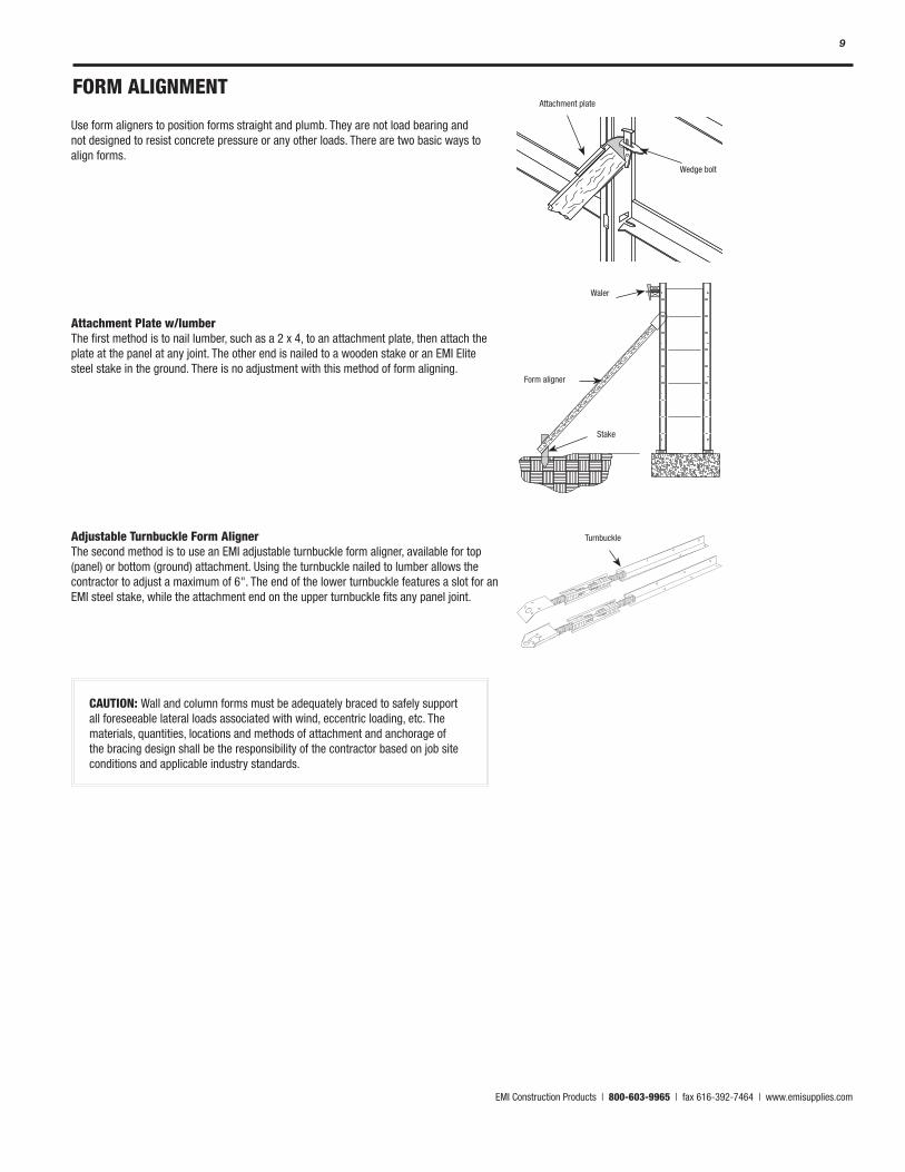
FORM ALIGNMENT
Use form aligners to position forms straight and plumb. They are not load bearing and not designed to resist concrete pressure or any other loads. There are two basic ways to align forms.
Attachment Plate w/lumber The first method is to nail lumber, such as a 2 x 4, to an attachment plate, then attach the plate at the panel at any joint. The other end is nailed to a wooden stake or an EMI Elite steel stake in the ground. There is no adjustment with this method of form aligning.
Adjustable Turnbuckle Form Aligner The second method is to use an EMI adjustable turnbuckle form aligner, available for top (panel) or bottom (ground) attachment. Using the turnbuckle nailed to lumber allows the contractor to adjust a maximum of 6". The end of the lower turnbuckle features a slot for an EMI steel stake, while the attachment end on the upper turnbuckle fits any panel joint.
CAUTION: Wall and column forms must be adequately braced to safely support all foreseeable lateral loads associated with wind, eccentric loading, etc. The materials, quantities, locations and methods of attachment and anchorage of the bracing design shall be the responsibility of the contractor based on job site conditions and applicable industry standards.
Attachment plate
Wedge bolt
Waler
Form aligner
Stake
Turnbuckle
EMI Construction Products | 800-603-9965 | fax 616-392-7464 | www.emisupplies.com
10
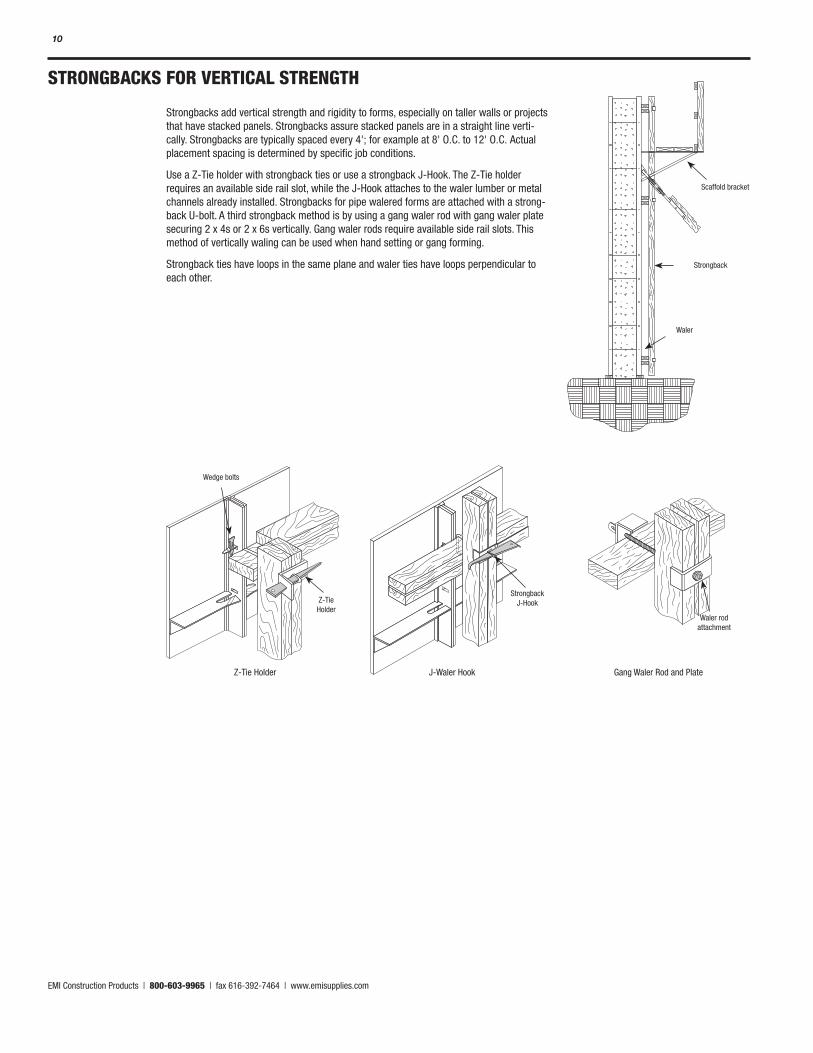
STRONGBACKS FOR VERTICAL STRENGTH
Strongbacks add vertical strength and rigidity to forms, especially on taller walls or projects that have stacked panels. Strongbacks assure stacked panels are in a straight line verti-cally. Strongbacks are typically spaced every 4'; for example at 8' O.C. to 12' O.C. Actual placement spacing is determined by specific job conditions.
Use a Z-Tie holder with strongback ties or use a strongback J-Hook. The Z-Tie holder requires an available side rail slot, while the J-Hook attaches to the waler lumber or metal channels already installed. Strongbacks for pipe walered forms are attached with a strong-back U-bolt. A third strongback method is by using a gang waler rod with gang waler plate securing 2 x 4s or 2 x 6s vertically. Gang waler rods require available side rail slots. This method of vertically waling can be used when hand setting or gang forming.
Strongback ties have loops in the same plane and waler ties have loops perpendicular to each other.
Z-Tie Holder J-Waler Hook Gang Waler Rod and Plate
Z-Tie Holder
Wedge bolts
Strongback J-Hook
Waler rod attachment
Scaffold bracket
Strongback
Waler
EMI Construction Products | 800-603-9965 | fax 616-392-7464 | www.emisupplies.com
11
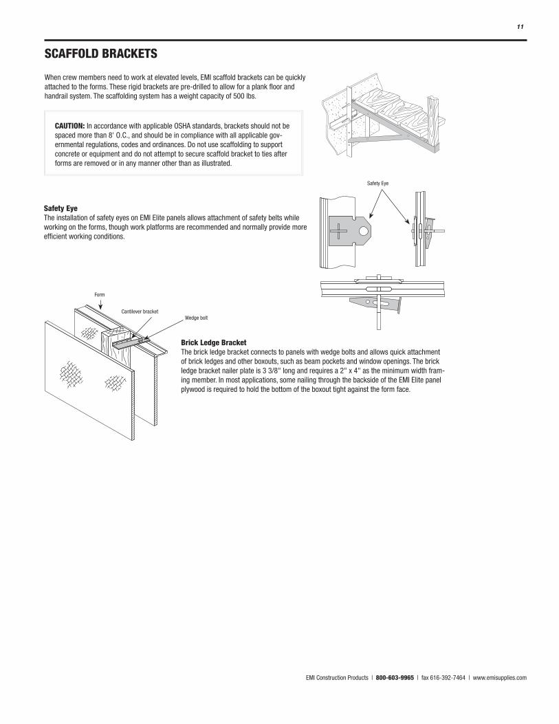
SCAFFOLD BRACKETS
When crew members need to work at elevated levels, EMI scaffold brackets can be quickly attached to the forms. These rigid brackets are pre-drilled to allow for a plank floor and handrail system. The scaffolding system has a weight capacity of 500 lbs.
CAUTION: In accordance with applicable OSHA standards, brackets should not be spaced more than 8' O.C., and should be in compliance with all applicable gov-ernmental regulations, codes and ordinances. Do not use scaffolding to support concrete or equipment and do not attempt to secure scaffold bracket to ties after forms are removed or in any manner other than as illustrated.
Safety Eye
Form
Cantilever bracketWedge bolt
Safety Eye The installation of safety eyes on EMI Elite panels allows attachment of safety belts while working on the forms, though work platforms are recommended and normally provide more efficient working conditions.
Brick Ledge Bracket The brick ledge bracket connects to panels with wedge bolts and allows quick attachment of brick ledges and other boxouts, such as beam pockets and window openings. The brick ledge bracket nailer plate is 3 3/8" long and requires a 2" x 4" as the minimum width fram-ing member. In most applications, some nailing through the backside of the EMI Elite panel plywood is required to hold the bottom of the boxout tight against the form face.
EMI Construction Products | 800-603-9965 | fax 616-392-7464 | www.emisupplies.com
12
FORMING FOOTINGS
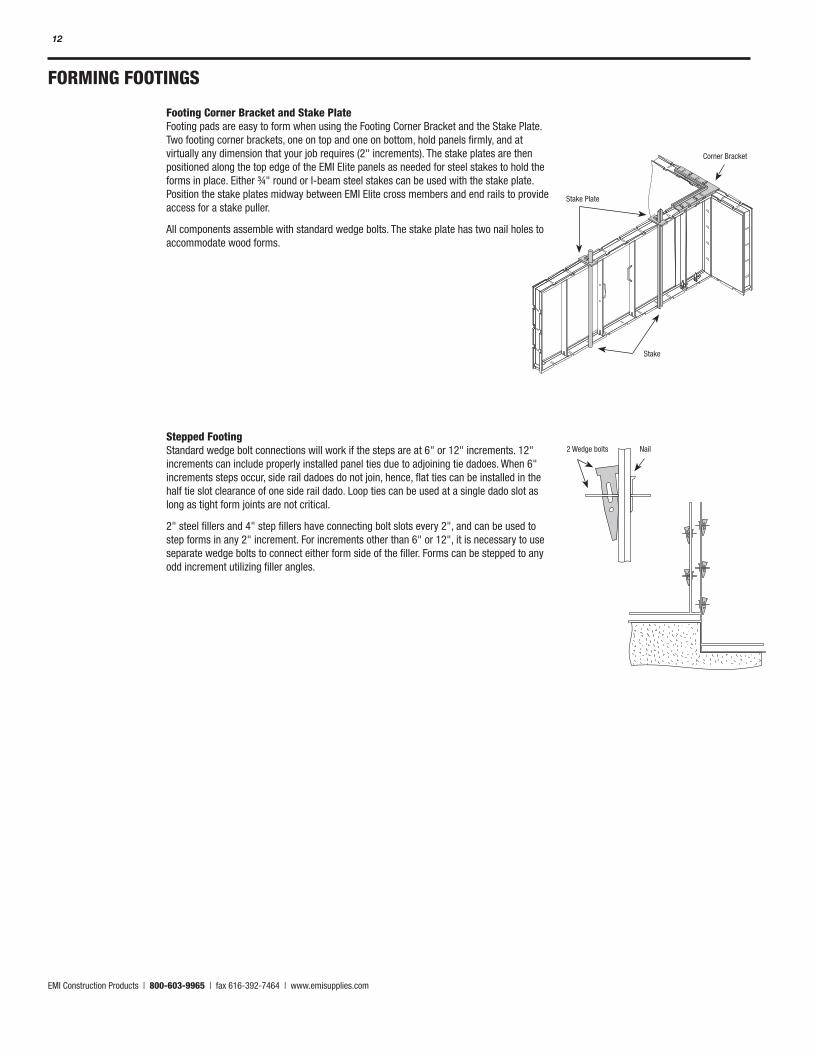
Footing Corner Bracket and Stake Plate Footing pads are easy to form when using the Footing Corner Bracket and the Stake Plate. Two footing corner brackets, one on top and one on bottom, hold panels firmly, and at virtually any dimension that your job requires (2" increments). The stake plates are then positioned along the top edge of the EMI Elite panels as needed for steel stakes to hold the forms in place. Either ¾" round or I-beam steel stakes can be used with the stake plate. Position the stake plates midway between EMI Elite cross members and end rails to provide access for a stake puller.
All components assemble with standard wedge bolts. The stake plate has two nail holes to accommodate wood forms.
Stepped Footing Standard wedge bolt connections will work if the steps are at 6" or 12" increments. 12" increments can include properly installed panel ties due to adjoining tie dadoes. When 6" increments steps occur, side rail dadoes do not join, hence, flat ties can be installed in the half tie slot clearance of one side rail dado. Loop ties can be used at a single dado slot as long as tight form joints are not critical.
2" steel fillers and 4" step fillers have connecting bolt slots every 2", and can be used to step forms in any 2" increment. For increments other than 6" or 12", it is necessary to use separate wedge bolts to connect either form side of the filler. Forms can be stepped to any odd increment utilizing filler angles.
2 Wedge bolts Nail
Stake
Stake Plate
Corner Bracket
EMI Construction Products | 800-603-9965 | fax 616-392-7464 | www.emisupplies.com
13
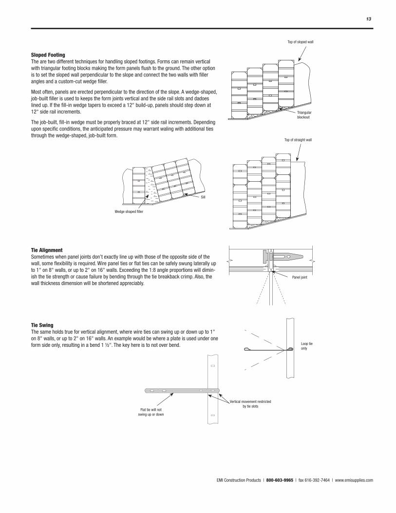
Sloped Footing The are two different techniques for handling sloped footings. Forms can remain vertical with triangular footing blocks making the form panels flush to the ground. The other option is to set the sloped wall perpendicular to the slope and connect the two walls with filler angles and a custom-cut wedge filler.
Most often, panels are erected perpendicular to the direction of the slope. A wedge-shaped, job-built filler is used to keeps the form joints vertical and the side rail slots and dadoes lined up. If the fill-in wedge tapers to exceed a 12" build-up, panels should step down at 12" side rail increments.
The job-built, fill-in wedge must be properly braced at 12" side rail increments. Depending upon specific conditions, the anticipated pressure may warrant waling with additional ties through the wedge-shaped, job-built form.
Tie Alignment Sometimes when panel joints don’t exactly line up with those of the opposite side of the wall, some flexibility is required. Wire panel ties or flat ties can be safely swung laterally up to 1" on 8" walls, or up to 2" on 16" walls. Exceeding the 1:8 angle proportions will dimin-ish the tie strength or cause failure by bending through the tie breakback crimp. Also, the wall thickness dimension will be shortened appreciably.
Tie Swing The same holds true for vertical alignment, where wire ties can swing up or down up to 1" on 8" walls, or up to 2" on 16" walls. An example would be where a plate is used under one form side only, resulting in a bend 1 ½". The key here is to not over bend.
Top of sloped wall
Triangular blockout
Top of straight wall
Wedge shaped filler
Sill
Panel joint
Loop tie only
Vertical movement restricted by tie slots
Flat tie will not swing up or down
EMI Construction Products | 800-603-9965 | fax 616-392-7464 | www.emisupplies.com
14
CORNERS Outside Corner Steel-ply Side Rail
Crossmember
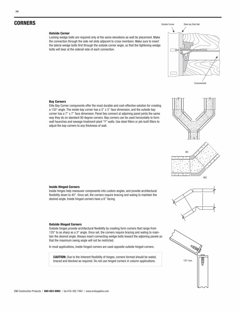
Outside Corner Locking wedge bolts are required only at the same elevations as wall tie placement. Make the connection through the side rail slots adjacent to cross members. Make sure to insert the lateral wedge bolts first through the outside corner angle, so that the tightening wedge bolts will bear at the siderail side of each connection.
Bay Corners Elite Bay Corner components offer the most durable and cost-effective solution for creating a 135° angle. The inside bay corner has a 3" x 3" face dimension, and the outside bay corner has a 7" x 7" face dimension. Panel ties connect at adjoining panel joints the same way they do on standard 90 degree corners. Bay corners can be used horizontally to form wall haunches and sewage treatment plant “Y” walls. Use steel fillers or job-built fillers to adjust the bay corners to any thickness of wall.
Inside Hinged Corners Inside hinges help maneuver components into custom angles, and provide architectural flexibility down to 45°. Once set, the corners require bracing and waling to maintain the desired angle. Inside hinged corners have a 6" facing.
Outside Hinged Corners Outside hinges provide architectural flexibility by creating form corners that range from 135° to as sharp as a 5° angle. Once set, the corners require bracing and waling to main-tain the desired angle. Always insert connecting wedge bolts toward the adjoining panels so that the maximum swing angle will not be restricted.
In most applications, inside hinged corners are used opposite outside hinged corners.
CAUTION: Due to the inherent flexibility of hinges, corners formed should be waled, braced and blocked as required. Do not use hinged corners in column applications.
IBC
OBC
135° max.
EMI Construction Products | 800-603-9965 | fax 616-392-7464 | www.emisupplies.com
15
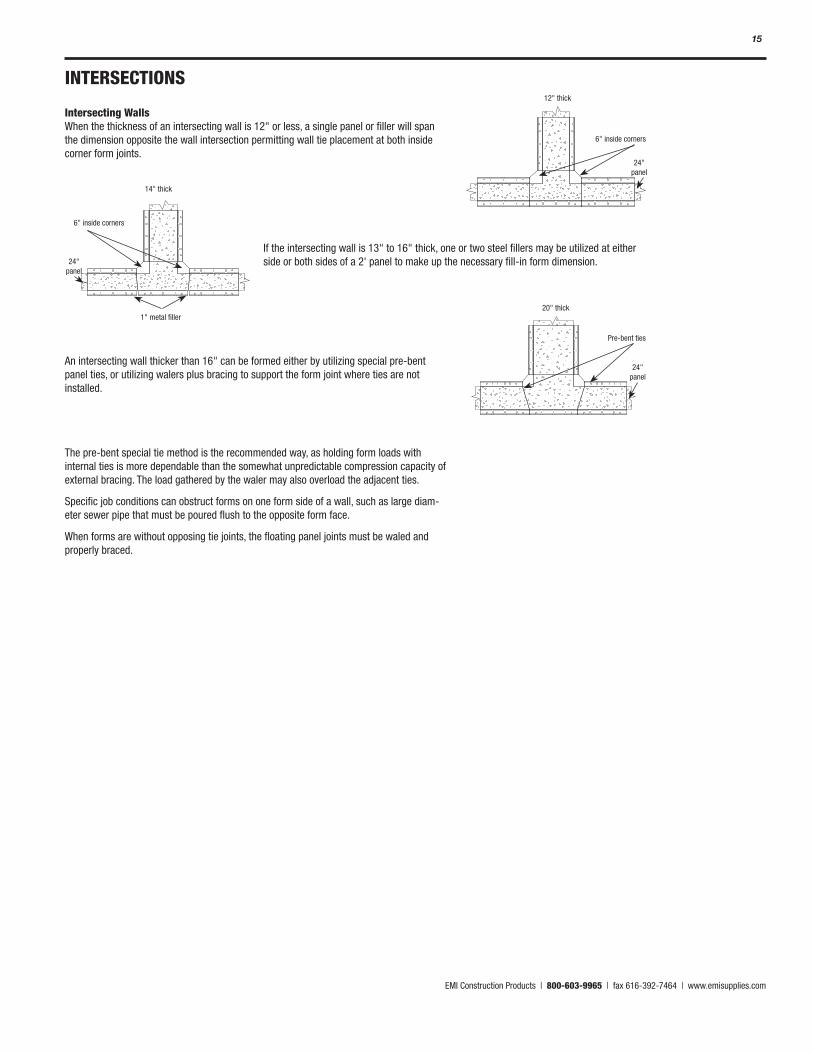
Intersecting Walls When the thickness of an intersecting wall is 12" or less, a single panel or filler will span the dimension opposite the wall intersection permitting wall tie placement at both inside corner form joints.
An intersecting wall thicker than 16" can be formed either by utilizing special pre-bent panel ties, or utilizing walers plus bracing to support the form joint where ties are not installed.
The pre-bent special tie method is the recommended way, as holding form loads with internal ties is more dependable than the somewhat unpredictable compression capacity of external bracing. The load gathered by the waler may also overload the adjacent ties.
Specific job conditions can obstruct forms on one form side of a wall, such as large diam-eter sewer pipe that must be poured flush to the opposite form face.
When forms are without opposing tie joints, the floating panel joints must be waled and properly braced.
12" thick
6" inside corners
24" panel
14" thick
6" inside corners
24" panel
1" metal filler20" thick
Pre-bent ties
24" panel
If the intersecting wall is 13" to 16" thick, one or two steel fillers may be utilized at either side or both sides of a 2' panel to make up the necessary fill-in form dimension.
INTERSECTIONS

EMI Construction Products | 800-603-9965 | fax 616-392-7464 | www.emisupplies.com
16
Column Forming Higher pressures due to a faster liquid-head rise are inherent to pouring concrete within the confined lateral dimensions of a column. All siderails must also resist lateral side-pull loads that normally are not involved in straight wall panel-to-panel connections. For these reasons, column outside corners require connecting wedge bolts at slots adjacent to all panel cross members, plus at slots 6" from each panel or filler end rail, and at slots 6" from ends of each length of outside corner angle. Form and outside corner lengths are staggered to eliminate common joints.
Form Extension Bracket The EMI form extension bracket provides a sturdier way to vertically extend your forms. The extension bracket attaches to the tops of forms using standard wedge bolts. Three holes are provided for screws to attach 2 x 4 lumber. Lumber will be flush with form face. To secure extensions, nail lumber across to each side or screw down x-flat ties across the top of lumber.
FORM EXTENSIONS
EMI Construction Products | 800-603-9965 | fax 616-392-7464 | www.emisupplies.com
17
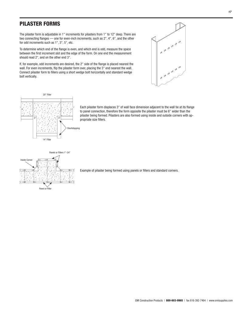
PILASTER FORMS
The pilaster form is adjustable in 1" increments for pilasters from 1" to 12" deep. There are two connecting flanges — one for even-inch increments, such as 2", 4", 6", and the other for odd increments such as 1", 3", 5", etc.
To determine which end of the flange is even, and which end is odd, measure the space between the first increment slot and the edge of the form. On one end the measurement should read 2", and on the other end 3".
If, for example, odd increments are desired, the 2" side of the flange is placed nearest the wall. For even increments, flip the pilaster form over, placing the 3" end nearest the wall. Connect pilaster form to fillers using a short wedge bolt horizontally and standard wedge bolt vertically.
20" Filler
14" Filler
3" 3"
Shortstopping
Inside Corner
Panel or Filler
Panels or Fillers 1"-24"
Each pilaster form displaces 3" of wall face dimension adjacent to the wall tie at its flange to panel connection, therefore the form opposite the pilaster must be 6" wider than the pilaster being formed. Pilasters are also formed using inside and outside corners with ap-propriate size fillers.
Example of pilaster being formed using panels or fillers and standard corners.
EMI Construction Products | 800-603-9965 | fax 616-392-7464 | www.emisupplies.com
18
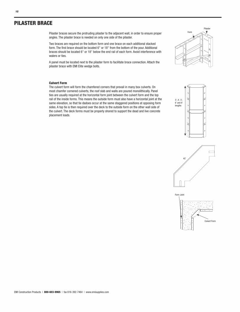
PILASTER BRACE
Pilaster braces secure the protruding pilaster to the adjacent wall, in order to ensure proper angles. The pilaster brace is needed on only one side of the pilaster.
Two braces are required on the bottom form and one brace on each additional stacked form. The first brace should be located 6" or 18" from the bottom of the pour. Additional braces should be located 6" or 18" below the end rail of each form. Avoid interference with walers or ties.
A panel must be located next to the pilaster form to facilitate brace connection. Attach the pilaster brace with EMI Elite wedge bolts.
Culvert Form The culvert form will form the chamfered corners that prevail in many box culverts. On most chamfer cornered culverts, the roof slab and walls are poured monolithically. Panel ties are usually required at the horizontal form joint between the culvert form and the top rail of the inside forms. This means the outside form must also have a horizontal joint at the same elevation, so that tie dadoes occur at the same staggered positions at opposing form sides. A top tie is then required over the deck to the outside form on the other wall side of the culvert. The deck forms must be properly shored to support the dead and live concrete placement loads.
45˚
3', 4', 5', 6' and 8' lengths
Pilaster
Form
Form Joint
Culvert Form
EMI Construction Products | 800-603-9965 | fax 616-392-7464 | www.emisupplies.com
19
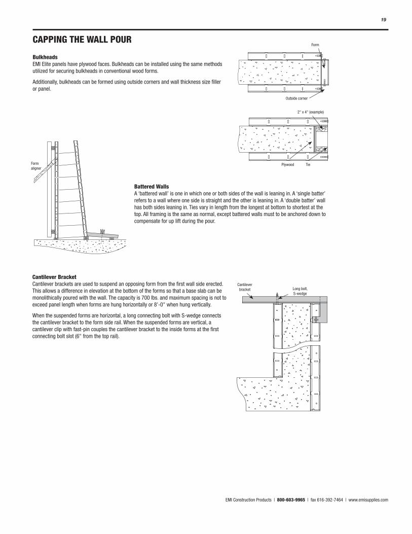
CAPPING THE WALL POUR
Bulkheads EMI Elite panels have plywood faces. Bulkheads can be installed using the same methods utilized for securing bulkheads in conventional wood forms.
Additionally, bulkheads can be formed using outside corners and wall thickness size filler or panel.
Form
Plywood Tie
2" x 4" (example)
Form aligner
Cantilever bracket Long bolt,
S-wedge
Battered Walls A ‘battered wall’ is one in which one or both sides of the wall is leaning in. A ‘single batter’ refers to a wall where one side is straight and the other is leaning in. A ‘double batter’ wall has both sides leaning in. Ties vary in length from the longest at bottom to shortest at the top. All framing is the same as normal, except battered walls must to be anchored down to compensate for up lift during the pour.
Cantilever Bracket Cantilever brackets are used to suspend an opposing form from the first wall side erected. This allows a difference in elevation at the bottom of the forms so that a base slab can be monolithically poured with the wall. The capacity is 700 lbs. and maximum spacing is not to exceed panel length when forms are hung horizontally or 8'-0" when hung vertically.
When the suspended forms are horizontal, a long connecting bolt with S-wedge connects the cantilever bracket to the form side rail. When the suspended forms are vertical, a cantilever clip with fast-pin couples the cantilever bracket to the inside forms at the first connecting bolt slot (6" from the top rail).
Outside corner
EMI Construction Products | 800-603-9965 | fax 616-392-7464 | www.emisupplies.com
20
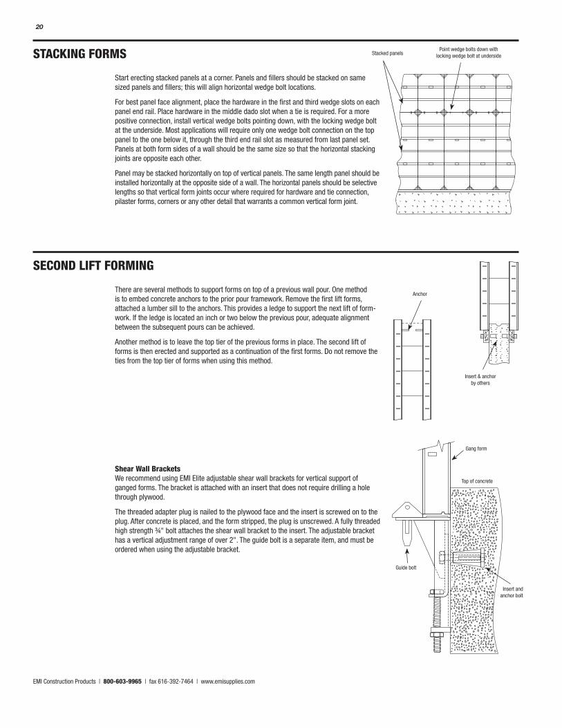
STACKING FORMS
Start erecting stacked panels at a corner. Panels and fillers should be stacked on same sized panels and fillers; this will align horizontal wedge bolt locations.
For best panel face alignment, place the hardware in the first and third wedge slots on each panel end rail. Place hardware in the middle dado slot when a tie is required. For a more positive connection, install vertical wedge bolts pointing down, with the locking wedge bolt at the underside. Most applications will require only one wedge bolt connection on the top panel to the one below it, through the third end rail slot as measured from last panel set. Panels at both form sides of a wall should be the same size so that the horizontal stacking joints are opposite each other.
Panel may be stacked horizontally on top of vertical panels. The same length panel should be installed horizontally at the opposite side of a wall. The horizontal panels should be selective lengths so that vertical form joints occur where required for hardware and tie connection, pilaster forms, corners or any other detail that warrants a common vertical form joint.
SECOND LIFT FORMING
There are several methods to support forms on top of a previous wall pour. One method is to embed concrete anchors to the prior pour framework. Remove the first lift forms, attached a lumber sill to the anchors. This provides a ledge to support the next lift of form-work. If the ledge is located an inch or two below the previous pour, adequate alignment between the subsequent pours can be achieved.
Another method is to leave the top tier of the previous forms in place. The second lift of forms is then erected and supported as a continuation of the first forms. Do not remove the ties from the top tier of forms when using this method.
Shear Wall Brackets We recommend using EMI Elite adjustable shear wall brackets for vertical support of ganged forms. The bracket is attached with an insert that does not require drilling a hole through plywood.
The threaded adapter plug is nailed to the plywood face and the insert is screwed on to the plug. After concrete is placed, and the form stripped, the plug is unscrewed. A fully threaded high strength ¾" bolt attaches the shear wall bracket to the insert. The adjustable bracket has a vertical adjustment range of over 2". The guide bolt is a separate item, and must be ordered when using the adjustable bracket.
Anchor
Gang form
Guide bolt
Insert and anchor bolt
Top of concrete
Insert & anchor by others
Stacked panelsPoint wedge bolts down with
locking wedge bolt at underside
EMI Construction Products | 800-603-9965 | fax 616-392-7464 | www.emisupplies.com
21
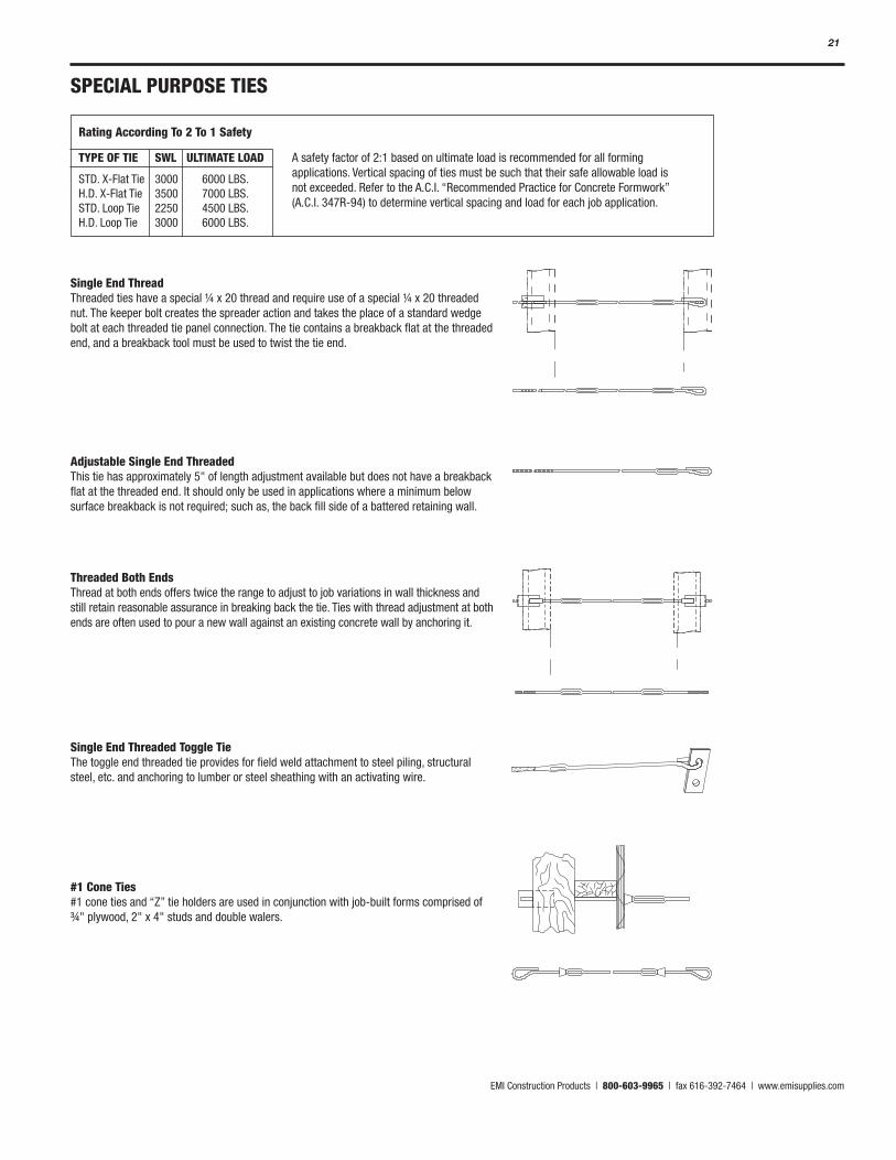
SPECIAL PURPOSE TIES
Single End Thread Threaded ties have a special ¼ x 20 thread and require use of a special ¼ x 20 threaded nut. The keeper bolt creates the spreader action and takes the place of a standard wedge bolt at each threaded tie panel connection. The tie contains a breakback flat at the threaded end, and a breakback tool must be used to twist the tie end.
Adjustable Single End Threaded This tie has approximately 5" of length adjustment available but does not have a breakback flat at the threaded end. It should only be used in applications where a minimum below surface breakback is not required; such as, the back fill side of a battered retaining wall.
Threaded Both Ends Thread at both ends offers twice the range to adjust to job variations in wall thickness and still retain reasonable assurance in breaking back the tie. Ties with thread adjustment at both ends are often used to pour a new wall against an existing concrete wall by anchoring it.
Single End Threaded Toggle Tie The toggle end threaded tie provides for field weld attachment to steel piling, structural steel, etc. and anchoring to lumber or steel sheathing with an activating wire.
#1 Cone Ties #1 cone ties and “Z” tie holders are used in conjunction with job-built forms comprised of ¾" plywood, 2" x 4" studs and double walers.
TYPE OF TIE SWL ULTIMATE LOAD
STD. X-Flat Tie 3000 6000 LBS. H.D. X-Flat Tie 3500 7000 LBS. STD. Loop Tie 2250 4500 LBS. H.D. Loop Tie 3000 6000 LBS.
Rating According To 2 To 1 Safety
A safety factor of 2:1 based on ultimate load is recommended for all forming applications. Vertical spacing of ties must be such that their safe allowable load is not exceeded. Refer to the A.C.I. “Recommended Practice for Concrete Formwork” (A.C.I. 347R-94) to determine vertical spacing and load for each job application.
EMI Construction Products | 800-603-9965 | fax 616-392-7464 | www.emisupplies.com
22
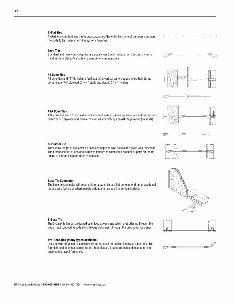
X-Flat Ties Available in standard and heavy duty capacities, the x-flat tie is one of the more common methods to tie modular forming systems together.
Loop Ties Standard and heavy duty loop ties are usually used with modular form systems when a hand set is in place. Available in a number of configurations.
#2 Cone Ties #2 cone ties and “Z” tie holders facilitate tying vertical panels opposite job-built forms comprised of ¾" plywood, 2" x 4" studs and double 2" x 4" walers.
#2A Cone Ties #2A cone ties and “Z” tie holders will connect vertical panels opposite job-built forms com-prised of ¾" plywood and double 2" x 4" walers directly against the plywood (no studs).
S-Pilaster Tie The overall length of a pilaster tie positions opposite wall panels at a given wall thickness. The breakback flat at one end is moved inboard to establish a breakback point on the tie ahead of a brick ledge or other type boxout.
Base Tie Connector The base tie connector will secure either a panel tie or a flat tie to an end rail or a side rail resting on a footing or where panels butt against an existing vertical surface.
S-Base Tie The S-base tie has an up-turned open loop at each end which protrudes up through the bottom rail connecting bolts slots. Wedge bolts insert through the protruding loop ends.
Pre-Bent Ties (many types available) Unusual wall shapes on occasion warrant the need for special factory pre-bent ties. The form joint points of connection for pre-bent ties are predetermined and located on the engineering layout furnished.
EMI Construction Products | 800-603-9965 | fax 616-392-7464 | www.emisupplies.com
23
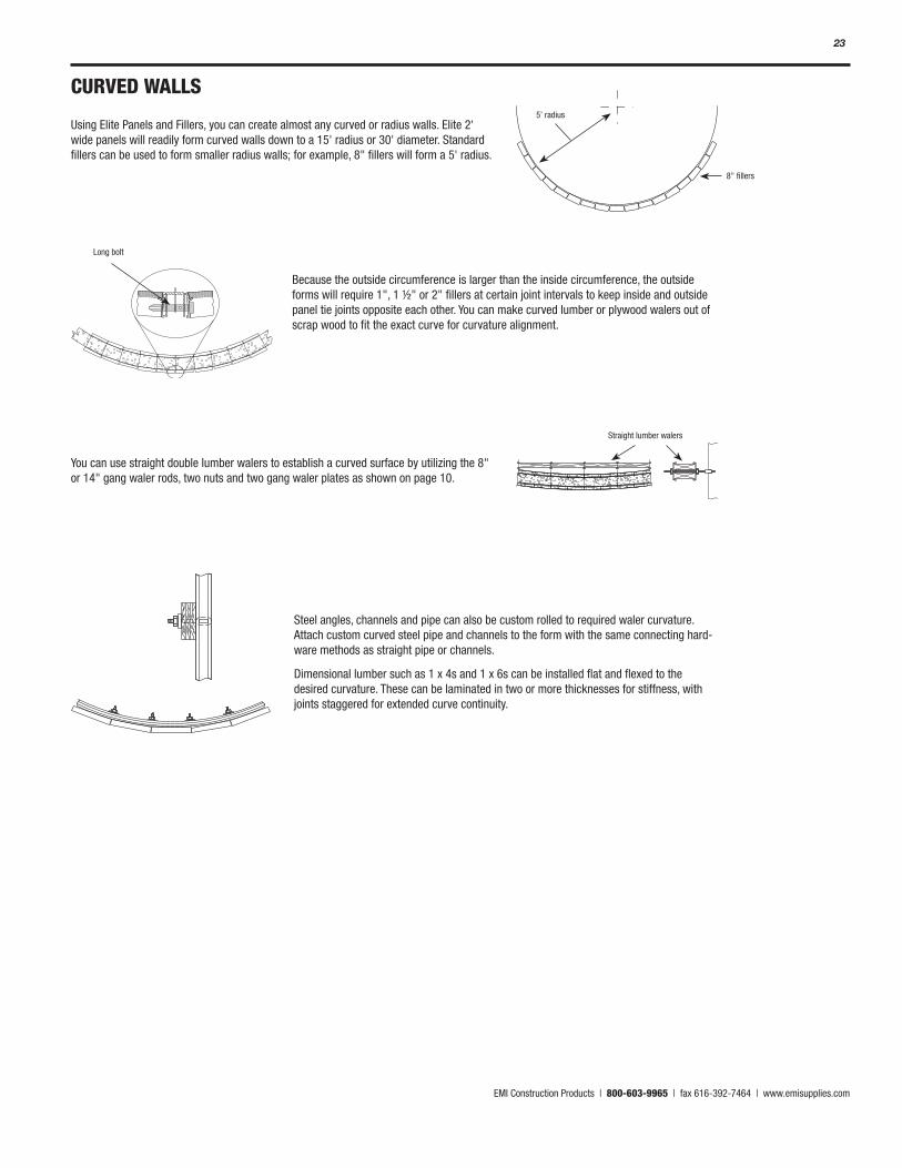
CURVED WALLS
Using Elite Panels and Fillers, you can create almost any curved or radius walls. Elite 2' wide panels will readily form curved walls down to a 15' radius or 30' diameter. Standard fillers can be used to form smaller radius walls; for example, 8" fillers will form a 5' radius.
You can use straight double lumber walers to establish a curved surface by utilizing the 8" or 14" gang waler rods, two nuts and two gang waler plates as shown on page 10.
8" fillers
5’ radius
Straight lumber walers
Long bolt
Because the outside circumference is larger than the inside circumference, the outside forms will require 1", 1 ½" or 2" fillers at certain joint intervals to keep inside and outside panel tie joints opposite each other. You can make curved lumber or plywood walers out of scrap wood to fit the exact curve for curvature alignment.
Steel angles, channels and pipe can also be custom rolled to required waler curvature. Attach custom curved steel pipe and channels to the form with the same connecting hard-ware methods as straight pipe or channels.
Dimensional lumber such as 1 x 4s and 1 x 6s can be installed flat and flexed to the desired curvature. These can be laminated in two or more thicknesses for stiffness, with joints staggered for extended curve continuity.
EMI Construction Products | 800-603-9965 | fax 616-392-7464 | www.emisupplies.com
24
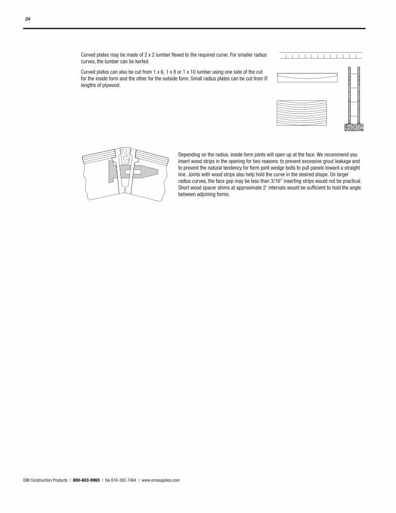
Curved plates may be made of 2 x 2 lumber flexed to the required curve. For smaller radius curves, the lumber can be kerfed.
Curved plates can also be cut from 1 x 6, 1 x 8 or 1 x 10 lumber using one side of the cut for the inside form and the other for the outside form. Small radius plates can be cut from 8’ lengths of plywood.
Depending on the radius, inside form joints will open up at the face. We recommend you insert wood strips in the opening for two reasons: to prevent excessive grout leakage and to prevent the natural tendency for form joint wedge bolts to pull panels toward a straight line. Joints with wood strips also help hold the curve in the desired shape. On larger radius curves, the face gap may be less than 3/16" inserting strips would not be practical. Short wood spacer shims at approximate 2' intervals would be sufficient to hold the angle between adjoining forms.
EMI Construction Products | 800-603-9965 | fax 616-392-7464 | www.emisupplies.com
25
WIRE TIE GANG FORMING
Large sections of EMI Elite panels and fillers can be assembled first — or ganged together — then set into place using a crane. Gang form ties are much the same as heavy duty (wire) panel ties, the difference being the extended loop-to-loop length of the gang form ties allows you to break off the tie without disassembling the panels. The loop of the tie is held in position behind the forms by use of the gang form bolt, twist the tie to break it inside of the concrete, and remove the tie end. With the tie ends removed, the ganged forms can remain assembled for setting and stripping.
Form Alignment Alignment should be installed on one side of a wall only. It is neither necessary nor desir-able to align both sides. Alignment on both sides can “squeeze” the wall thickness, causing the condition described previously. Also, it can interfere with proper load distribution on the ties. Generally, it is best to set and align one side, set the other using spacers and position ties at top and bottom before securing the other ties.
NOTE: Refer to form alignment section on page 9.
Gang Forms Ganged forms can be assembled by laying the forms on any reasonably flat surface. Lay 2 x 4 or 2 x 6 lumber under the horizontal joints of the panels. Place the panels face down on the lumber and insert the hardware in the panel side rails. Connect wedge bolts 6" from the corners of all panels and 6" from the midpoint of 6' or 8' panel side rails.
Use 2 x 4, 2 x 6 and 2 x 8 lumber for walers and strongbacks for straight gangs. The combined depth of the lumber for walers and strongbacks should not exceed 12". As an example, double 2 x 4s might be used as walers and double 2 x 6s or 2 x 8s used as verti-cal strongbacks. Gang form ties connect directly to the panel side rails with gang form bolts; therefore, walers and strongbacks are used for alignment of panels only. Since the walers and strongbacks are not used to contain the concrete pressure, very few are required compared to job-built lumber forming methods. Walers and strongbacks should be located so they do not interfere with tie placement. Dado slots are provided at the rear of the panel side rails and are located at 6" and 18" from the top and bottom of panels for hardware attachment.
As an example, let us assume that we will build a gang with a 12' height by using 6' panels. We would align the panels horizontally by attaching 8" gang water rods at the 1'-6", 6'-6" and 10'-6" elevations and place double 2 x 4 or 2 x 6 walers across the panels at these locations. The walers would be secured with gang water plates, and double 2 x 6 vertical strongbacks are attached to the walers with one 14" gang waler rod and two gang waler plates.
EMI Construction Products | 800-603-9965 | fax 616-392-7464 | www.emisupplies.com
26
STRIPPING FORMS
Forms can usually be stripped at any point after you remove the walers and connecting hardware. Usually, it is easier to start stripping forms at an outside corner, or adjacent to a 1", 1 ½" or 2" filler. Get a bucket or some other container for the hardware so you don’t lose any. Keep your material costs down; you can reuse what you don’t lose.
Hopefully, you used a quick release agent, like Elite and Greenkote, and the panels release easily.
We recommend you breakback the ties within two days after stripping. With wire ties, a ½ to ¾ twist will break them back. Flat ties are broken off by a firm hammer blow hitting the edge of the tie as shown. A blow against the flat side of the tie will bend the tie.
Tie Removal When the gang is at an elevation above ground, it is recommended that gang form bolts be removed, ties broken back and the gang detached from adjacent forms beginning at the bottom and working upwards. This is a safety precaution, which allows the man to get off of the ganged form at the top of the wall before he releases the final hardware and top row of ties. At this time, the crane should be attached to the gang life brackets.
CAUTION: When stripping flat ties, be careful, wear protective clothing and safety glasses when striking ties with a hammer during the stripping process.
EMI Construction Products | 800-603-9965 | fax 616-392-7464 | www.emisupplies.com
27
NOTES
EMI Construction Products | 800-603-9965 | fax 616-392-7464 | www.emisupplies.com
28
526 E. 64th StreetHolland, MI 49423p. (800) 603-9965 f. (616) 392-7464emisupplies.com [email protected]
01.09