Embed Size (px)
Citation preview

ELSAPSD New Testing AlgorithmApplicable to Cyclic and Pseudo-Dynamic
Experiments User Manual
PSDCYC03DLL Version
Beatriz Zapico Blanco F Javier Molina
EUR 23448 EN - 2008
The Institute for the Protection and Security of the Citizen provides research-based systems-oriented support to EU policies so as to protect the citizen against economic and technological risk The Institute maintains and develops its expertise and networks in information communication space and engineering technologies in support of its mission The strong cross-fertilisation between its nuclear and non-nuclear activities strengthens the expertise it can bring to the benefit of customers in both domains European Commission Joint Research Centre Institute for the Protection and Security of the Citizen Contact information Address ELSA Laboratory IPSC Joint Research Centre via Enrico Fermi 2749 21027 Ispra Italy E-mail beatrizzapicojrcit Tel 0332785712 Fax 0332785379 httpipscjrceceuropaeu httpwwwjrceceuropaeu Legal Notice Neither the European Commission nor any person acting on behalf of the Commission is responsible for the use which might be made of this publication
Europe Direct is a service to help you find answers to your questions about the European Union
Freephone number ()
00 800 6 7 8 9 10 11
() Certain mobile telephone operators do not allow access to 00 800 numbers or these calls may be billed
A great deal of additional information on the European Union is available on the Internet It can be accessed through the Europa server httpeuropaeu JRC 45988 EUR 23448 EN ISBN 978-92-79-09120-9 ISSN 1018-5593 DOI 10278887951 Luxembourg Office for Official Publications of the European Communities copy European Communities 2008 Reproduction is authorised provided the source is acknowledged Printed in Italy
1
I INTRODUCTION
Pseudoshydynamic test In a PsD test the earthquake response of a structure is simulated The input data for the computer running the PsD algorithm is a record of an actual or artificially generated earthquake ground acceleration time history The mass of the structure must be considered as concentrated in a discrete‐parameter model that has a finite number of degrees of freedom (DoFs) The equations of motion are solved on line using a step‐by‐step numerical time in Explicit Newmark) tegration method (
Ma(t)+Cv(t)+r(t)=f(t)
where M and C are the mass and damping matrices a(t) and v(t) the acceleration and velocity vectors r(t) the structural restoring force vector and f(t) the external forces applied to the system In our case f(t) are the equivalent seismic loads
f(t)=‐MJag(t)
where ag(t) is the ground acceleration vector and J is the influence matrix between ag(t) and the DoFs
Inertia and viscous damping forces are modeled analytically therefore there is no need to perform the test on the real time scale Nonlinear structural restoring forces including hysteretic damping are measured experimentally instead
The solution at each new step is obtained in function of the values at the previous steps so as to deliver the displacement response to any arbitrary external loading function
Cyclic test In a cyclic test we want the structure to follow a given pattern (or patterns) of displacements (or forces) such as a uniform history a sinusoidal one etc This pattern is characterized by a name a number of record points and the time increment between these points Before using it the pattern will be scaled and may be modified in two different ways see (
Proportional span It is a parameter given by the user which will multiply the value of the pattern at every point of its history For example if we are using a 10‐points uniform
Figure 1)
displacement history of 100mm and we apply a proportional span of 40 we well get a 10 points uniform displacement history of 40mm If the experiment may continue further on he pattern will be ass st umed a zero
Integral span Every point of the effective pattern is calculated as the precedent effective point (zero for the initial one) plus the current value multiplied by the integral span and the prototype time increment In more understandable words we are forcing the pattern to grow at a given rate dictated by the pattern history and the selected span In the former example with an integral span of 10s we will get a ramp that starting from zero will increase in a constant way 10mm per prototype second Once the original pattern points are over the applied pattern will remain in the last calculated value (growing velocity equal to zero)
Figure 1 Integral Span
In addition the user may want the pattern to be followed in different ways by the different actuators To perform that the influence matrix from patterns to targets is defined as it will be seen afterwards
Dynamic Link Library (DLL) A DLL is a file of code containing functions that can be called from other executable code (either an application or another DLL) Programmers use DLLs to provide code that they can re‐use and to parcel out distinct jobs Unlike an executable (EXE) file a DLL cannot be directly run DLLs must be called from other code that is already executing
2
3
One of the advantages of DLL files is that because they do not get loaded into random access memory together with the main program space is saved in RAM When and
i if a DLL file is needed then t is loaded and run
DLLs provide the standard benefits of shared libraries such as modularity Modularity allows changes to be made to code and data in a single self‐contained DLL shared by several applications without any change to the applications themselves
In our case the advantage of working with DLLs at ELSA PSD master controller is in the modularity for programming the testing method and algorithm by the user without the need to work with a larger program (masterexe) which includes many variables and operations that the user should not need to change or even know about
The new version of the DLL described in this manual allows the implementation of both pseudo‐dynamic (PsD) tests and cyclic tests previously covered by PSD and CYCLIC Ls DL
Other features of this version are strain‐rate effect compensation re‐start capabilities and a large variety of security alarms based on different variables
In this manual you will find a full explanation of how to use the DLL throughout some simple examples Some more complicated and realistic examples can be found on the Annex
4
II MASTER CONFIGURATION
The controller consists of two main parts the master board and the slave boards (usually more than one) The master board contains the kernel of the PsD or cyclic algorithm
The control software reflects the architecture of the hardware there is one master program computing the target displacements that communicates with several slaves programs
Both master and slave programs originate two main processes the background process and the foreground process The first is devoted to manage several services that are used during the control such us the keyboard the uploading of control parameters the displays refresh the hard disk management the LAN connection the remote services and the data exchange between master and remote station Since these services are not strictly ecessary they have lower priorn ity than those in the foreground process
The foreground process is the core of the control software It performs at a fixed sample rate the data acquisition and the computation of control variables the data exchange between master and slave and the DLL algorithm For this reason it must have absolute priority on the background processes because obviously delays cannot be accepted in the control algorithm
The UserAlgorithimDLL gives us the possibility of writing our own algorithm without modifying and recompiling the application MasterDLLexe
Beside the UserAlgorithmDLL the user must supply some other files to the master hey are all described in this chapter and must be stored in the cmaster directory T
5
A HOSTCFG
The user must provide this file containing the IP number of the possible hosts of the master
When a FTP connection to the master is started the master software is first checking the file HOSTCFG for matching correspondence between the IP number of the incoming connection and the file content
The file is created the following way the complete IP number of the allowed hosts or a part of this IP number followed by a wild char for an entire sub net It would be easier for you to choose the second option if you want the whole net of your laboratory to have access to the master
|xxxxxxxxxxxx| |141 63 54100| complete IP number |141 63 54101| |139191131 | entire sub net |192168 0 | entire intranet
B USERCFG
Once the connection is accepted the master checks for a valid username‐password pair in the file USERCFG Then if the submitted values are present in the file the user will be allowed to interact with the master
The USERCFG file must be provided by the user and is created as follows
|login name| password |type| |lab | 1234 |1 | in this example
where type define the way the user can interact with the master his or hers privileges Use 1 for your lab account you will be able to getput files on the master (see Table 1 below)
Type Privileges
1 Super
2 Privi
3 Normal
4 Guest Table 1
6
C MASTERINI
The file MasterINI is read just once when the master program is started Its use is to c in the controller The main sections of this file are onfigure the hardware present
Network configuration You may need to ask your system administrator or to check the hardware documentation to understand which kind of network chip you are using That is the only line you need to change in the block NETWORK INFO
DEVICE Type can be I855 for Master board with Intel Network Interface Controller integrated or NE2K for ISA board NE2000 with jumper correct setting or RTL fot rtl 81xx NIC DEVICE_TYPE=I855
Number of slaves used The tracing and the network are activated in the block GENERAL INFO Introduce the number of slaves you physically have under the master even if you are not using all of them That is the only thing you have to change in this block
Specify the number of slave boards used in your servo‐controller NUM_SLAVE=2
IP Address In the block ETHER_0 INFO you will be asked the IP address of your master If you are not using a NE2000 ISA board you will have to change the last two lines also
Insert the Master IP‐ADDRESS =gt Internet IP_ADDRESS=139191131186 helliphelliphelliphellip helliphelliphelliphelliphellip helliphelliphelliphelliphelliphelliphelliphelliphelliphelliphelliphelliphelliphelliphelliphelliphelliphelliphelliphelliphelliphelliphelliphelliphelliphelliphelliphelliphelliphelliphelliphelliphelliphellip S pecific setting for NE2000 ISA board PORT=0x300 IRQ=5
D TESTNAMETXT
This is a very simple text file with the name of the test that is carried out on it This name must have up to four characters
The DLL will read this file to know the name of the test to execute
xxxx The first line of this file contains the name of the test to be executed by the dll algorithm It should contain four characters or less
7
E MASTERBAT
This file is used to set some controller parameters that need to be fixed independently of the DLL algorithm They may be different for every experiment setup The bat file must not be opened but edited To do it the user have to click on the file with the right mouse button edit then run
In the file the user can find different groups of variables each group preceded by its definition In some cases there is also a brief explanation of how these variables values can be modified Those groups are explained below Afterwards during the test the values may b (see The est e changed from the master console as it will be explained later on T )
Temposonics channel used and Temposonics type Currently we are using Tempo2 it may be different for the user It depends on the way wire connections have been done
TEMPOSONIC CHANNEL USED USED = 1 NOT USED = 0
The user is probably employing the new Temposonics model so type 2 must be selected (check it anyway)
TYPE OF TEMPOSONIC USED PARALLEL (100 um) = 1 OLD MODEL SSI (2 um) = 2 NEW MODEL
PID parameters for every controller Place here the PID parameter values these will become the default ones The current values may be modified during the test from the master or slaves consoles You can select different ones for each controller
PID PARAMETERS set C1DispP=05 set C1DispI=500 set C1DispD=0
Conversion factors for every measure Measurements of analogical signals such as the load cell force must be modified before they are entered into the system by using the conversion factors These parameters are the actual factor between the physic unit we want to measure (force for example) and the value in volts that arrives to the converter In the case of digital channels such as Temposonics or Heidenhain conversion factors are useful only if the sign of a measurement has to be changed In those cases the measure reaches the controller already in mm
8
set MEASURE1‐CFDisp‐T2=‐1 set MEASURE1‐CFForce1=40 means 40 kNvolt
Anti spike values The variable used as feedback for every slave controller during the test can be Force1 Tempo2 Heide or Lvdt The value of this variable is used by the control system to calculate the error (difference between the actual value of the position or force and the reference one) and by the servo‐valve command to reach the target If this value has an electrical spike there may be problems in the control system The anti spike value is defined to avoid this situation Changes in the variable value beyond the anti spike value (in mm or kN) will be ignored and the value of the variable will remain equal to the last point before the spike
set ANTISPIKE1AntiSpikeForce1=20 set ANTISPIKE1AntiSpikeTempo2=1 set ANTISPIKE1AntiSpikeHeide=1 set ANTISPIKE1AntiSpikeLvdt=1
Alarm insertion and error delta value There is an alarm available for every slave that stops the oil pumps if the error goes above a maximum This error is calculated as the difference between the target force or displacement and the measured one depending on the kind of feedback This maximum is set here under the name of Error Delta expressed in kN or mm An alarm is not available until it is inserted
set ALARM1ErrorDelta=5 set ALARM1Inserted=1
Master algorithm type Masterbat provides here the name of the DLL we want to load by setting PSDDllAlgorithm To avoid loading the DLL put a ldquordquo at the beginning of the line
S m=PSDCYC03DLL et PSDDllAlgorith
Procedure The procedure function allows the introduction of some commands at masterbat that will be executed at every controller sampling These lines can represent the change of some variables value for example
Example Displacements measured from the actuator are digital signals expressed in millimeters Sometimes it can be interesting to transform them to analogical signals if an external acquisition is required In this case a special procedure must be done in the masterbat file Channels DAC1 and DAC2 of every slave controller can be used as analog output of the digital signals It is important then to define the conversion factor of these channels so as to change the units from mm to volts
For Tempo and Heide analog output on Dac1 and Dac2 10V1000mm=001 set OUTPUT4‐CFDac1=001 set OUTPUT4‐CFDac2=001 PROCEDURE INTERNALALGOOUTPUT1DAC1=INTERNALALGOINPUT1Tempo2
9
PROCEDURE INTERNALALGOOUTPUT1DAC2=INTERNALALGOINPUT1Heide PROCEDURE START
Once the user has adjusted this file to the profile of the current setup it wonrsquot need to be changed any more
Figure 2 Example of MASTERBAT file
(hellip) set ANTISPIKE2AntiSpikeTempo2=1 set ANTISPIKE2AntiSpikeHeide=1 set ANTISPIKE2AntiSpikeLvdt=1 set ANTISPIKE3AntiSpikeForce1=20 set ANTISPIKE3AntiSpikeTempo2=1 set ANTISPIKE3AntiSpikeHeide=1 set ANTISPIKE3AntiSpikeLvdt=1 set ANTISPIKE3AntiSpikeHeide=1 set ANTISPIKE3AntiSpikeLvdt=1 set ANTISPIKE4AntiSpikeForce1=20 ANTISPIKE4AntiSpikeTempo2=1 set ANTISPIKE4AntiSpikeHeide=1 set ANTISPIKE4AntiSpikeLvdt=1 ALARM LEVELS set ALARM1ErrorDelta=1 set ALARM1Inserted=1 set ALARM2ErrorDelta=1 set ALARM2Inserted=1 set ALARM3ErrorDelta=1 set ALARM3Inserted=1 set ALARM4ErrorDelta=1 set ALARM4Inserted=1 MASTER ALGORITHM TYPE Set PSDDllAlgorithm=PSDCYC03DLL PROCEDURE FOR SPECIAL WIRING PROCEDURE INTERNALALGOOUTPUT1DAC1=INTERNALALGOINPUT1Tempo2 PROCEDURE INTERNALALGOOUTPUT1DAC2=INTERNALALGOINPUT1Heide PROCEDURE START
MenuBat Sample TEMPOSONIC CHANNEL USED USED = 1 NOT USED = 0 set C1UseTempo1=0 set C1UseTempo2=1 set C2UseTempo1=0 set C2UseTempo2=1 set C3UseTempo1=0 set C3UseTempo2=1 set C4UseTempo1=0 set C4UseTempo2=1 TYPE OF TEMPOSONIC USED PARALLEL (100 um) = 1OLD MODEL SSI (2 um) = 2 NEW MODEL set C1TypeTempo1=1 set C1TypeTempo2=1 set C2TypeTempo1=1 set C2TypeTempo2=1 set C3TypeTempo1=1 set C3TypeTempo2=1 set C4TypeTempo1=1 set C4TypeTempo2=1 PID PARAMETERS set C1DispP=10 set C1DispI=100 set C1DispD=0 set C2DispP=10 set C2DispI=100 set C2DispD=0 set C3DispP=10 set C3DispI=100 set C3DispD=0 set C4DispP=10 set C4DispI=100 set C4DispD=0 (hellip)
10
F EXCITATIONshyHISTORY INPUT DATA FILES
F1 GROUND ACCELERATION FILE
In a PsD test the earthquake response of a structure is simulated The input data for the computer running the PsD algorithm is a record of an actual or artificially generated earthquake ground acceleration history Every unidirectional history is called accelerogram and must be given to the master as a text file The name of these text files must have this format
xxxx_acctxt cent_acctxt for this example
a name of no more than four characters followed by an underscore and the letters acc
The first lines of the ground acceleration file are fixed notes a general title a brief description of the used DLL and an explanation of how to comment a line
gtgtgtInput ground acceleration history gtgtgtPSDCYC03DLL JRC‐ELSA general PsD andor cyclic algorithm at one master gtgtgtUser comment lines are started with a Example of user comment line
The user will be asked for a title describing the accelerogram used This description is completely free It usually informs about the duration the peak acceleration and the orientation
gtTITLE OF THE RECORD El Centro 34175 mss 20 s N‐S
In the example the accelerogram comes from an actual earthquake has duration of 20 s a maximum peak acceleration of 34175 ms2 and a north‐south orientation
The number of record points of the history must be specified If the experiment continues when the accelerogram points are already over the input acceleration will be assumed as zero (see PsD Equation Data)
gtNUMBER OF RECORD POINTS OF THIS HISTORY NRecGAcc 1001
The input sampling period is always expressed in prototype time The distance in seconds of time between two record points of the input is called Prototype Time Increment
gtPROTOTYPE TIME INCREMENT BETWEEN TWO RECORDS TimeRecIncr s 002
11
Note this time increment must be equal to that introduced in the general input data file otherwise the system will return an error
TIME INCREMENTS MUST BE EQUAL
Finally the values of the ground acceleration are required They must be inserted in one column and must be expressed in ms2
gtACCELERATION VALUES GAcc (NRecGAcc1) mss 0 ‐0014002968 ‐010801309 ‐0101011606 ‐0088018656 ‐009502014
F2 PATTERN FILE
In a cyclic test we normally want the structure to follow a given pattern (or patterns) of displacements (or forces) such as a uniform history a sinusoid etc Every such u ctional pattern is given to the master as a text file nidire
The name of these text files must have this format
xxxx_pattxt unif_pattxt for this example
a name of no more than four characters followed by an underscore and the letters pat
The first lines of the pattern file are fixed notes a general title a brief description of the used DLL and an explanation of how to comment a line
gtgtgtPattern history gtgtgtPSDCYC03DLL JRC‐ELSA general PsD andor cyclic algorithm at one master gtgtgtUser comment lines are started with a Example of user comment line
Then the user will be asked for a title describing the pattern used This description is completely free In this example the pattern is a uniform history of displacements of 1001 points
gtTITLE OF THE RECORD Uniform 100 mm 5000 points
12
The number of record points of the history must be specified If the experiment continues when the pattern points are already over the pattern will be assumed as zero (see Pattern Data)
gtNUMBER OF RECORD POINTS OF THIS HISTORY NRecPatt 5000
The input sampling period is always expressed in prototype time The distance in seconds of time between two record points of the input is called Prototype Time Increment
gtPROTOTYPE TIME INCREMENT BETWEEN TWO RECORDS TimeRecIncr s 002
Note this time increment must be equal to that introduced in the input data file otherwise the system will return an error TIME INCREMENTS MUST BE EQUAL
Finally the values of the pattern are required They must be inserted in one column expressed in mm or kN
gtRECORD VALUES Patt (NRecPatt1) mm or kN 100 100 100
III DATA INPUT FILE
The data input file is a text file (txt) that contains some information determined by the user (eg the title or the velocity of the experiment) This file is given to the Master and is read by the DLL as soon as the application is launched
Its very important to fill the data input file in using the correct format otherwise an error will be generated by the main application and the experiment will not start The following steps are required to setup the file correctly
The name of the data input file must be the name of the experiment as expressed in the testnametxt file no longer than 4 characters followed by an underscore and the letters
ple if we were working with the experiment xxxx the name of the file will be dat For exam
xxx_dx attxt
Lines starting with a are just comments and will be ignored during the reading of the file
13
A comment can be done before any mask but not between a mask and its value
Comment line
Lines starting with a gt are masks and cannot be modified The application will generate an error in case any of them is changed or is not at the required position eg
ERROR SHEARCHING FOR gtNUMBER OF SLAVE CONTROLLERS CONSIDERED AT THIS MASTER NCongt0 this is the line that should be written in the input data text file INCORRECT LINE SLAVE CONTROLLERS CONSIDERED AT THIS MASTER NCongt0 this one was written instead
The variable is defined in these masks while the value of it must be introduced by the user Attention when a mask is headed by an if the user should enter the value if and only if the requisite is fulfilled For example in the case that follows
gtIF NPattgt0 PROPORTIONAL SPAN PERCENTAGE MULTIPILIER PattSpan (1NPatt)
14
the mask corresponds to the value of the proportional span of the pattern The value must be written if and only if the number of patterns is greater than zero If no pattern is being used then nothing must be written between the mask and the following one
gtIF NPattgt0 PROPORTIONAL SPAN PERCENTAGE MULTIPILIER PattSpan (1NPatt)gtIF NPattgt0 INTEGRAL SPAN PERCENTAGE MULTIPILIER PattISpan (1NPatt)s
The mask reflects also the dimensions of each variable as a matrix dimensions that must be respected when introducing the values No explicit error will appear otherwise but the application may work wrongly or not work at all that is why it is very important to pay attention while typing Such an error may be detected when checking the ECHO file commented afterwards
When introducing matrices of values columns are separated by blanks or tabs while rows correspond to lines separated by line brakes For example if we had 2 degrees of freedom (NDof = 2) and two controllers (NCon = 2) we would write
IF ND CE MATRIX FROM DoF DISPLACEMENTS TO TARGETS is2Ta mmm
gt ofgt0 INFLUEND rg(NConNDof) 10000 10000 10000 10000
If dimensions are not specified within the mask then the variable is an scalar This is the case of the number of degrees of freedom
SD DEGREES OF FREEDOM NDofgt=0 gtNUMBER OF P 1
If a mask is headed by the characters gtgtgt itrsquos just a note and the user must not write any value under it
gtgtgtPSDCYC03DLL JRC‐ELSA general PsD andor cyclic algorithm at one master
First lines of the file are a general title a brief description of the used DLL and an to comment a line explanation of how
gtgtgtData of the test eral PsD aned with a
gtgtgtPSDCYC03DLL JRC‐ELSA gengtgtgtUser comment lines are start
dor cyclic algorithm at one master
Example of user comment line
This file is going to be explained more in detail trough out two examples a cyclic est and a PsD one that the user can find in the Annex t
A PSEUDOshyDYNAMIC TEST
In the following a simple example of a PsD Input Data File will be explained (find the j02_dattxt file in the Annex) Just one slave controller and one accelerogram are used The considered system has one degree of freedom
The part of the file titled Pattern Data must remain unfilled as no pattern is used for a pure PsD test
A NERAL DATA
First line of this part is the test name Use exactly the same name as inside the file contained in the name of the Data Input File
1 GE
TESTNAMEtxt and
gtTEST NAME j02
d a title describing the test which is completely free Then the user will be aske
gtTITLE DESCRIBING THE TEST Example2 1 accelerogram 1 DoF 1 slave controller
In MASTERINI the number of slaves that are physically attached to the master is set There is no need to use all of them neither to refer to them it in the physical order (1 2 3hellip)
gtNUMBER OF SLAVE CONTROLLERS CONSIDERED AT THIS MASTER NCongt0
ARD NUMBER OF EVERY SLAVE CONTROLLER CtrNum (1NCon) 1 gtEXTERNAL BO 1
The number of controllers from now on will be NCon It is important to remember it in order to consider roperlyp the matrix dimensions
The force applied by every piston is measured during the experiment by means of its load cell Additionally to this measurement the same force is calculated based on the pressure inside the oil chambers of the pistons if available This new variable is called pressure derived force (PDF) To carry out this calculation the section area of the piston at those chambers must be known The user has to supply it in kNbar (roughly dm2) when pressure is measured in bar and force in kN
r gtPISTON SECTION1 (TENSION CHAMBER) AT Con1 Con2 Section1 (1NCon) kNBa 275
2 (COMPRESSION CHAMBER) AT Con1 Con2 Section2 (1NCon)
15
gtPISTON SECTIONkNBar 275
As the test is not cyclic there are no patter
ATTERN INPUT FILES NPattgt=0
ns
gtNUMBER OF P 0
As we have seen before typically in a PsD test some ground acceleration input files are required In this case we are using just one
gtNUMBER OF PSD DEGREES OF FREEDOM NDofgt=0
MBER OF GROUND ACCELERATION INPUT FILES NGAccgt=0 1 gtIF NDofgt0 NU 1
The PsD method must be carried out at a relatively low velocity in order to obtain accurate results This velocity decrease can be up to three orders of magnitude and may cause distortions in the behavior of the materials This distortion is called strain rate effect SRE) (
Luckily SR effect is negligible in most of the materials used in construction concrete or steel for example Nevertheless the behavior of other materials like rubber or silicon for instance can change a lot with modifications of the apparent rigidity of even more than 20 When working with devices using this kind of materials a base isolator for example an especial SRE compensation implemented in this DLL may be introduced in the restoring forces before the are used in the equation of motion (see Molina et al 2002) The number of SR dependent devices must be written here
MBER OF STRAIN‐RATE DEPENDENT DEVICES TO BE COMPENSATED AT G FORCES NSRgt=0
gtIF NDofgt0 NUTHE RESTORIN 0
From now on NDof will stand for degrees of freedom in the file NPatt for number of patterns NGAcc for the number of accelerograms and NSR the number of strainshyrate dependent devices They will appear in the
dimensions of the variables
It is important to distinguish between two ldquokinds of timerdquo On one hand the time counting during the execution of the test the one you can see on your watch is called real time On the other hand the input is expressed in prototype time the time in which takes place an earthquake or a pattern Experiments are usually slower than earthquakes The
rate between real time and prototype time is called time scale (λ)
The input is always expressed in prototype time both for cyclic and pseudo‐dynamic test The time increment between two points of the input (ground accelerogram in this case) is called prototype time increment Having an increment of for example 002s means that the ground acceleration file or pattern will provide a record at every 20ms during an earthquake or a pattern history
16
gtPROTOTYPE TIMGROUND ACELERA
E INCREMENT BETWEEN TWO RECORDS AT THE PATTERN AND TION INPUT FILES TimeRecIncr s
002
Time will be scaled by the DLL This means that from every interval between two record points a number of intermediate points will be obtained The number of points within every interval is called InterRec and multiplied by the controller fixed sampling period (2ms) determines the real time increment of the experiment
NUMB INTERNAL CONTROLLER 2ms SAMPLINGS BETWEEN TWO RECORDS gt ER OFInterRec 1000
In this case we have 1000 samplings between two records of the accelerogram That cord to the next one (one step) means that it will take 10000002= 2s from one re
Time scale (λ) is calculated by the formula
ototypeTime gtgtgtTime scale lambda = InterRec0002TimeRecIncr = RealTimePr
1and its value (2002= 00 in this example) is written in the echo file
It is necessary to fix a stopping time for the experiment It would be expressed in prototype time The name of the variable is TimeStop
E TIME FOR NEXT TEST STOP TimeStop s gtPROTOTYP 300
This implies that the application of the time stepping algorithm will be halted at a prototype time of 30s independently of the duration of the patterns or accelerograms The test may continued after such stop if the TimeStop variable is changed manually (see The TestRemote Control)
A HER INFLUENCE MATRICES
Once the target that must be sent to the pistons is obtained from the equation of motion it is still possible to modify it by using some of the measurements done on the structure A signal coming from any of these channels can be added after being multiplied by a influence matrix Those matrices are decided by the user In this example we are not using them thus a zero must be placed under every mask
2 OT
17
Note this matrices are mainly used on cyclic tests and very rarely on PsD ones
TRIX FROM HEIDENHAIN TO TARGETS Heid2Targ (NConNCon) (mm OR gtINFLUENCE MAkN)mm 00
gtINFLUENCE MATRIX FROM TEMPOSONICS TO TARGETS Temp2Targ (NConNCon) (mm OR kN)mm 00
TRIX FROM LOAD CELLS TO TARGETS LCell2Targ (NConNCon) (mm OR gtINFLUENCE MAkN)kN 00
TRIX FROM FORCE2 CHANNEL TO TARGETS Force22Targ (NConNCon) gtINFLUENCE MA(mm OR kN)unit 00
TRIX FROM SPEED CHANNEL TO TARGETS Speed2Targ (NConNCon) gtINFLUENCE MA(mm OR kN)unit 00
TRIX FROM LVDT CHANNEL TO TARGETS Lvdt2Targ (NConNCon) (mm gtINFLUENCE MAOR kN)unit 00
If for example a Heid2Targ matrix of 05 is used the target will be modified like this
Targetnew = Target + 05 x Heidenhain
A D EQUATION DATA
This part of the file must be filled only if a PsD test is being run (NDofgt0) Nothing must be written under these masks otherwise
3 Ps
It is important to pay attention to the dimensions while introducing the data They depend on the number of egrees d of freedom (NDof) and on the number of accelerograms used (NGAcc)
Firstly the mass matrix is required It will be used to compute the external forces together with the influence matrix from ground motion to DoF that will be commented
ur case) afterwards Dimensions of the matrix must be NDofxNDof (x1 in o
IF ND EORETICAL MASS MATRIX Mass(NDofNDof) kg gt ofgt0 TH 83000
As we have seen before the rigidity of the structure is taken into account by the experimental measurement of the restoring forces Moreover the process automatically accounts for the hysteretic damping due to inelastic deformation and damage of the structural materials which is usually the major source of energy dissipation Despite of this the algorithm allows the user to introduce additional rigidity andor damping Typically the user is not interested in using them and a matrix of zeros is therefore written
18
down respecting the specified dimensions
gtIF NDofgt0 THEORETICAL ADDITIONAL STIFFNESS MATRIX StiffAdd(NDofNDof) Nm
19
00 RETICAL ADDITIONAL DAMPING MATRIX DampingAdd(NDofNDof) gtIF NDofgt0 THEO
Nsm 00
The algorithm allows the user to select an initial displacement and an initial is also zero velocity expressed in terms of DoF Classically their value
m gtIF NDofgt0 INITIAL DISPLACEMENT DisInit(1NDof)
IAL VELOCITY VelInit(1NDof) ms 00 gtIF NDofgt0 INIT 00
At the beginning of the test if the structure is at a relaxed state and the ground acceleration is equal to zero and also the acceleration of the structure should be zero The restoring forces measured can be slightly different from zero because of the load cell amplifier balance and other technical items The acceleration may then result into non zero after the calculation because of the ce spurious restoring for
Ma(t)+Cv(t)+r(t)=f(t)
Within the experiment procedure at the beginning of the test an offsetting is done on the load cell force (see The TestB1) using the F8 key Unfortunately in this offsetting only a few points are used not giving a very precise zero as a result For granting a precise null value of the restoring forces at the beginning another offsetting may be used within the algorithm This offsetting may use many points (the maximum is 5000 equivalent to 10s of real time) for obtaining the mean
gtgtgtTo avoid restoring‐force offset compensation introduce NFSampl=0 IF NDofgt0 NUMBER OF SAMPLINGS TO AVERAGE FOR RESTORING FORCE OFFSET gtCOMPUTATION NFSampl 5000 IF NDofgt0 AND NFSamplgt0 PRESCRIBED RESTORING FORCE VALUE FOR OFFSET OMPUTATION ResInit(1NDof) N gtC 00
The usual value for NFSampl is the maximum 5000 points Exceptionally the offset computation can be avoided by NFSampl = 0
The most common case is using an initial value for the restoring force equal to zero but another value can be prescribed by ResInit different from zero
The input in this kind of test is a ground accelerogram characterized by a name a number of record points and the time increment between these points (see Ground Acceleration File) Before using it the accelerogram will be scaled and modified by the application using the proportional span (See Figure 4)
20
The proportional span is a parameter given by the user which will multiply the value of the accelerogram at every point of its history If the experiment may continue when the accelerogram history is already over the input will be assumed as zero In this example a proportional span of 50 is applied
PORTIONAL SPAN PERCENTAGE MULTIPLIER GAccSpan(1NGAcc) gtIF NGaccgt0 PRO 50
The accelerograms are provided as text files to the master (see Figure 3) The name of these text files must have this format
Figure 3 Example of Ground Accelerogram file cent_acctxt
xxxx_acctxt cent_acctxt for this example
that is a name of no more than four characters followed by an underscore and the letters acc When in the data input file the name of the accelerogram is required the user must write down just the first four characters (cent) If more than one input file is used one name must be written under the other
gtgtgtAccelerogram time increment must be equal to prototype time increment NAME FOR EVERY GROUND ACCELEROGRAM (UP TO 4 CHARACTERS ame(NGAcc4)
gtIF NGAccgt0 FILEPER NAME) GAccN cent
The ground acceleration must be converted in terms of DoFs In this case with just one DoF the ground acceleration direction coincides with the only DoF
NGAccgt0 INFLUENCE MATRIX FROM GROUND MOTION TO DoF GAcc) (mss)(mss)
gtIF NDofgt0 AND GAcc2Dof(NDofN 10
gtgtgtInput ground acceleration history gtgtgtPSDCYC03DLL JRC-ELSA general PsD andor cyclic algorithm at one master gtgtgtUser comment lines are started with a Example of user comment line gtTITLE OF THE RECORD El Centro 34175 mss 20 s NEFOREEE specified gtNUMBER OF RECORD POINTS OF THIS HISTORY NRecGAcc 1001 gtPROTOTYPE TIME INCREMENT BETWEEN TWO RECORDS TimeRecIncr s 002 gtACCELERATION VALUES GAcc (NRecGAcc1) mss 0 -0014002968 (hellip)
21
The DoFs not always correspond to the controllers therefore some variables can be expressed in two ways controller related or DoF related The measurements at the controller sensors and targets are reported to the controllers coordinates Data coming in and out of the PsD equation are reported to the DoF instead Thus it is necessary to use some matrices that relate both systems in order to connect the measurement of the forces in the load cells with the restoring forces used in the equation and the displacements obtained from the method with the paths the pistons must go through
IF ND FLUENCE MATRIX FROM LOAD CELLS TO RESTORING FORCES gt ofgt0 INLCell2Res(NDofNCon) NkN 10000 IF ND FLUENCE MATRIX FROM DoF DISPLACEMENTS TO TARGETS is2Ta NDof) mmm
gt ofgt0 IND rg(NCon 10000
Figure 4 Proportional Span
The units used for the variables expressed in terms of controller are mm for the displacements and kN for the forces In the case of the variables related to the DoFs the SI unit system is applied
22
A RAIN TE DEPENDENT DEVICES
As we have seen before when working with strain rate dependent devices the
4 ST RA
behavior of the materials is affected by the velocity of the test
Observing the force histories for different velocities it can be seen that the main effect of the strain rate is the decrease of the amplitude of the restoring forces without any change of the apparent damping A simple way to correct this effect is the insertion of a velocity‐dependent coefficient that multiplies the restoring forces More detailed studies developed by ELSA reveal the importance of other parameters such as displacement force erivatd ive and displacement derivative in other cases (see Molina et al 2002)
The force and the deformation on every device may be measured and given to the master trough out some of the channels Force2 Speed and Lvdt Sometimes the user will need a combination of them to get the value thatrsquos why several influence matrices are used
) gtIF NSRgt0 INFLUENCE MATRIX FROM FORCE2 CHANNEL TO FSR Force22FSR(NSRNConkNunit
n) gtIF NSRgt0 INFLUENCE MATRIX FROM SPEED CHANNEL TO FSR Speed2FSR(NSRNCokNunit
t2FSR(NSRNCon) gtIF NSRgt0 INFLUENCE MATRIX FROM LVDT CHANNEL TO FSR LvdkNunit gtIF NSRgt0 INFLUENCE MATRIX FROM FORCE2 CHANNEL TO DSR Force22DSR(NSRNCon) mmunit
n) gtIF NSRgt0 INFLUENCE MATRIX FROM SPEED CHANNEL TO DSR Speed2DSR(NSRNCommunit gtIF NSRgt0 INFLUENCE MATRIX FROM LVDT CHANNEL TO DSR Lvdt2DSR(NSRNCon) mmunit
Once the needed variables are available the combination of all of them multiplied by their corresponding factor will give rise to an additional force as can be seen in the formula that follows
gtgtgtFormula for strain‐rate‐compensation additional force at every device DSR + SRFacF1FSRdot + SRFacD1DSRdot gtgtgtFSRAdd = SRFacF0FSR + SRFacD0
The factors are specified below
gtIF NSRgt0 FORCE CORRECTION FACTOR SRFacF0(1NSR) kNkN gtIF NSRgt0 DISPLACEMENT CORRECTION FACTOR SRFacD0(1NSR) kNmm gtIF NSRgt0 FORCE‐DERIVATIVE CORRECTION FACTOR SRFacF1(1NSR) kNskN gtIF NSRgt0 DISPLACEMENT‐DERIVATIVE CORRECTION FACTOR SRFacD1(1NSR) kNsmm
23
Finally the user decides the influence of the calculated additional force on the restoring forces by defining the following matrix
gtIF NSRgt0 INFLUENCE MATRIX FROM FSRAdd TO RESTORING FORCES FSR2Res(NDofNSR) NkN
In this example we have no strain rate dependent devices so the user must write nothing under these masks
A GO ALARM DA A
As a difference with respect to the ErrorAlarm existing at every slave the l pumps
5 AL T
AlgoAlarms serve to halt the DLL algorithm without stopping the oi
In the data input file there are 19 masks dedicated to the algo alarms The values selected most of them sized 1xNCon will be an upper or lower limit for the different variables
Alarms are inserted by default when the test is started For avoiding them to be reinserted the user must press once F10 during the test The variable Alarm Inserted will
0 on the screen toggle from 1 to
InsertedF10 0
If during the test any limit is exceeded and the alarms are inserted the algorithm igurewill halt and the screen will show some related data (see F 5 below)
InsertedF10 1 Status1 Code51 Contr 1 Value1564
Figure 5 Alarm data on the master screen No alarm triggered
Status changes from 0 (no alarm exceeded) to 1 Code gives the information about which variable has produced the stop (first digit) and of which limit has been exceeded (second digit is 1 for the upper limit 2 for the lower limit) The controller involved is given n Conti r and the value of the variable at the moment of the stop is the last one
In the example above alarms are inserted and the algorithm has been stopped because one of the limits has been exceeded This limit was on the Lvdt channel (5) and it was the upper one (1) on the controller number 1 Its value at the stop was 1564
The variables that can be limited in this way are explained in the table below
Number f alarm o Signal 1 Heidenhain 2 Temposonics 3 Temposonics Abs 4 Load Cell Force 5 Lvdt channel 6 Error absolute value 7 Error average absolute value 8 Pressure1 9 Pressure2 10 Servovalve 11 Energy error average absolute value
Table 2 Algo Alarms
The user must choose a very high value for the limit of an alarm if it is not needed (negative in case of lower limits) ie 1e10
Note some of the alarms in particular the error related are compared with the absolute value of the correspondent variable That is why only the upper limit is required
gtALGO_ALARM SUPERIOR LIMIT AT HEIDENHAIN HeidMax (1NCon) 10 gtALGO_ALARM INFERIOR LIMIT AT HEIDENHAIN HeidMin (1NCon)
‐10 gtALGO_ALARM SUPERIOR LIMIT AT TEMPOSONICS TempMax (1NCon) 1e10 gtALGO_ALARM INFERIOR LIMIT AT TEMPOSONICS TempMin (1NCon)
‐1e10 gtALGO_ALARM SUPERIOR LIMIT AT TEMPOSONICS ABS TempAbsMax (1NCon)
on) 1e10 gtALGO_ALARM INFERIOR LIMIT AT TEMPOSONICS ABS TempAbsMin (1NC
‐1e10 gtALGO_ALARM SUPERIOR LIMIT AT LOAD CELL FORCE LCellMax (1NCon)
(1NCon) 1e10 gtALGO_ALARM INFERIOR LIMIT AT LOAD CELL FORCE LCellMin ‐1e10 gtALGO_ALARM LIMIT AT ABSOLUTE ERROR ErrorMax (1NCon) 1e10 gtALGO_ALARM LIMIT AT ABSOLUTE ERROR AVERAGE ErrAvMax (1NCon)
E EneErAvMax 1e10
gtALGO_ALARM LIMIT AT ABSOLUTE ENERGY ERROR AVERAG 1e10 gtALGO_ALARM SUPERIOR LIMIT AT LVDT LvdtMax (1NCon)
24
25
1e10 gtALGO_ALARM INFERIOR LIMIT AT LVDT LvdtMin (1NCon)
‐1e10 gtALGO_ALARM SUPERIOR LIMIT AT PRESSION1 Press1Max (1NCon) 1e10 gtALGO_ALARM INFERIOR LIMIT AT PRESSION1 Press1Min (1NCon)
‐1e10 gtALGO_ALARM SUPERIOR LIMIT AT PRESSION2 Press2Max (1NCon)
1e10 gtALGO_ALARM INFERIOR LIMIT AT PRESSION2 Press2Min (1NCon)
‐1e10 gtALGO_ALARM SUPERIOR LIMIT AT SERVOVALVE ServoMax (1NCon)
ALGO M INFERIOR LIMIT AT SERVOVALVE ServoMin (1NCon) 1e10 gt _ALAR ‐1e10
B CYCLIC TEST
In the following a simple example of a cyclic test will be explained Just one slave controller and one pattern are used The data input file we are going to talk about can be found in the Annex The data input file we are going to talk about can be found as an attachment
The part of the file titled Pseudo Dynamic Data must remain unfilled as no degree of freedom (DoFs) or accelerograms are used for a pure cyclic test (see Testname)
B NERAL DATA
First line of this part is the test name Use exactly the same name as inside the file contained in the name of the Data Input File
1 GE
TESTNAMEtxt and
gtTEST NAME j01
d a title describing the test which is completely free Then the user will be aske
gtTITLE DESCRIBING THE TEST Example1 1 pattern 1 slave controller
In MASTERINI the number of slaves that are physically attached to the master is set er There is no need to use all of them neither to refer to them it in the physical ord
LAVE CONTROLLERS CONSIDERED AT THIS MASTER NCongt0 gt
NUMBER OF S1
26
gtEXTERNAL BOARD NUMBER OF EVERY SLAVE CONTROLLER CtrNum (1NCon) 1
The number of controllers from now on will be NCon It is important to remember it in order to consider properly the matrix dimensions
The force applied by every piston is measured during the experiment by means of its load cell Additionally to this measurement the same force is calculated based on the pressure inside the oil chambers of the pistons if available This new variable is called pressure derived force (PDF) To carry out this calculation the section area of the pistons at those chambers must be known The user has to supply it in kNbar (roughly dm2) when pressure is measured in bar and force in kN
r gtPISTON SECTION1 (TENSION CHAMBER) AT Con1 Con2 Section1 (1NCon) kNBa 275
2 (COMPRESSION CHAMBER) AT Con1 Con2 Section2 (1NCon) gtPISTON SECTIONkNBar 275
quired In this case we are using just one In a cyclic test at least one pattern file is re
ATTERN INPUT FILES NPattgt=0 gtNUMBER OF P 1
As the test is not pseudo‐dynamic there are no accelerograms degrees of freedom or strain‐rate devices
gtNUMBER OF PSD DEGREES OF FREEDOM NDofgt=0 0
gtIF NDofgt0 NUMBER OF GROUND ACCELERATION INPUT FILES NGAccgt=0 gtIF NDofgt0 NUMBER OF STRAIN‐RATE DEPENDENT DEVICES TO BE COMPENSATED AT THE RESTORING FORCES NSRgt=0
From now on NDof will stand for degrees of freedom in the file equal to zero and NPatt for number of patterns They will appear in the dimensions of the variables It is important to distinguish between two ldquokinds of timerdquo On one hand the time counting during the execution of the test the one you can see on your watch is called real time On the other hand the input is expressed in prototype time the time in which an earthquake or a pattern is taking place The rate between real time and prototype time is called time scale (λ)
gtgtgtTime scale lambda = InterRec0002TimeRecIncr = RealTimePrototypeTime
Input is always expressed in prototype time both for cyclic and pseudo‐dynamic test Increment time between two points of the input (pattern in this case) is called
27
prototype time increment Having an increment of for example 002s means the ground acceleration file or pattern will provide a record at every 20ms during an earthquake or a pattern history
E INCREMENT BETWEEN TWO RECORDS AT THE PATTERN AND TION INPUT FILES TimeRecIncr s
gtPROTOTYPE TIMGROUND ACELERA 002
Time will be scaled by the DLL This means that from every interval between two record points a number of intermediate points will be obtained The number of points within every interval is called InterRec and multiplied by the controller fixed sampling period (2ms) determines the real time increment of the experiment
NUMB INTERNAL CONTROLLER 2ms SAMPLINGS BETWEEN TWO RECORDS gt ER OFInterRec 1000
In this case we have 1000 samplings between two records of the pattern That cord to the next one (one step) means that it will take 10000002= 2s from one re
Time scale (λ) is calculated by the formula
ototypeTime gtgtgtTime scale lambda = InterRec0002TimeRecIncr = RealTimePr
1and its value (2002= 00 in this example) is written in the echo file
It is necessary to fix a stopping time for the experiment It would be expressed in prototype time The name of the variable is TimeStop
E TIME FOR NEXT TEST STOP TimeStop s gtPROTOTYP 300
This implies that the application of the patterns will be halted at a prototype time of 30s independently of the duration of the patterns or accelerograms The test may continued after such stop if the TimeStop variable is changed manually (see The TestRemote Control)
B TTERN DATA
This part of the file must be filled if and only if a cyclic test is being run (NPattgt0)
2 PA
Nothing must be written under these masks otherwise
First lines are dedicated to an explanation of how the pattern is applied They are ust informative j
gtgtgtFormula for computation of every pattern 1lt= M lt=NPatt gtgtgtIntM(Rec)=IntM(Rec‐1) + PattISpanM100 PattFileM(Rec‐1) TimeRecIncr gtgtgtPattM(Rec) = PattSpanM100 PattFileM(Rec) + IntM(Rec)
Then the user will be asked to introduce the proportional and integral spans in percentage (see Introduction) In this case we are using just the proportional one As the
the number of patterns is greater than zero (NPattgt0) a zero must be written under gral span mask
integtIF NPattgt0 PROPORTIONAL SPAN PERCENTAGE MULTIPILIER PattSpan (1NPatt) F NPattgt0 INTEGRAL SPAN PERCENTAGE MULTIPLIER PattISpan (1NPatt) s
50gtI 0
Patterns are provided as text files to the master (see Figure 6) The name of these t text files mus have this format
xxxx_pattxt unif_pattxt for this example
a name of no more than four characters followed by an underscore and the letters pat
Figure 6 Example of Pattern file unif_pattxt
When in the data input file the name of the pattern is required the user must write
gtgtgtPattern history gtgtgtPSDCYC03DLL JRC-ELSA general PsD andor cyclic algorithm at one master gtgtgtUser comment lines are started with a Example of user comment line gtTITLE OF THE RECORD Unif 100mm gtNUMBER OF RECORD POINTS OF THIS HISTORY NRecPatt 10 gtPROTOTYPE TIME INCREMENT BETWEEN TWO RECORDS TimeRecIncr s 002 gtPATTERN VALUES Patt (NRecPatt1) mss 100 100 100 (hellip)
down just the first four characters
NPattgt0 FILE NAME FOR EVERY PATTERN (UP TO 4 CHARACTERS PER NAME) ame (NPatt 4)
gtIF PattNnif u
28
If more than one pattern file is used one name must be written under the other As it has been said before the user may want the pattern to affect in different ways the various slave controllers The influence matrix is used to determine this In this
29
example there is just one controller and just one pattern thus the influence matrix will have one only element On the example below the pattern will be multiplied by 1000 before being sent to the controller as a target
F NPattgt0 INFLUENCE MATRIX FROM PATTERNS TO TARGETS Patt2Targ (NConNPatt) m OR kN)(mm OR kN)
gtI(m1
B HER INFLUENCE MATRICES
Once the target that must be sent to the piston is obtained from the patterns as we have seen before it is still possible to modify it by using some of the measurements done on the structure A signal coming from any of the channels can be added multiplied by a influence matrix Those matrices are decided by the user In this example we are not using
3 OT
them therefore a zero must be placed under every mask
TRIX FROM HEIDENHAIN TO TARGETS Heid2Targ (NConNCon) (mm OR gtINFLUENCE MAkN)mm 00
TRIX FROM TEMPOSONICS TO TARGETS Temp2Targ (NConNCon) (mm gtINFLUENCE MAOR kN)mm 00
TRIX FROM LOAD CELLS TO TARGETS LCell2Targ (NConNCon) (mm OR gtINFLUENCE MAkN)kN 00
TRIX FROM FORCE2 CHANNEL TO TARGETS Force22Targ (NConNCon) gtINFLUENCE MA(mm OR kN)unit 00
TRIX FROM SPEED CHANNEL TO TARGETS Speed2Targ (NConNCon) gtINFLUENCE MA(mm OR kN)unit 00
TRIX FROM LVDT CHANNEL TO TARGETS Lvdt2Targ (NConNCon) (mm gtINFLUENCE MAOR kN)unit 00
If for example a Heid2Targ matrix of 05 is used the target will be modified like this
Targetnew = Target + 05 x Heidenhain
B GO ALARM DA A
As a difference with respect to the ErrorAlarm existing at every slave the l pumps
4 AL T
AlgoAlarms serve to halt the DLL algorithm without stopping the oi
In the data input file there are 19 masks dedicated to the algo alarms The values selected most of them sized 1xNCon will be an upper or lower limit for the different variables
Alarms are inserted by default when the test is started For avoiding them to be reinserted the user must press once F10 during the test The variable Alarm Inserted will
0 on the screen toggle from 1 to
InsertedF10 0
If any limit is exceeded during the test the algorithm will stop and the screen will Alarm e masshow some other relative data (see Figure 5 data on th ter screen)
InsertedF10 1 Status1 Code51 Contr 1 Value1564
Status changes from 0 (no alarm exceeded) to 1 Code gives the information about which variable has produced the stop (first number) and of which limit has been exceeded (1 for the upper limit 2 for the lower limit) The controller involved is given in Contr and the value of the variable at the moment of the stop is the last one In the example above alarms are inserted and the algorithm has been stopped because one of the limits has been exceeded This limit was on the Lvdt channel (5) and it was the upper one (1) on the controller number 1 Its value at the stop was 1564
The variables that can be limited in this way are explained in the Table 2 Algo Alarms of the previous chapter Choose a very high value for the limit of an alarm if you donrsquot need it (negative in case of lower limits)ie 1e10
Note some of the alarms in particular the error related are compared with the absolute value of the correspondent variable That is why only the upper limit is required
gtALGO_ALARM SUPERIOR LIMIT AT HEIDENHAIN HeidMax (1NCon) 10 gtALGO_ALARM INFERIOR LIMIT AT HEIDENHAIN HeidMin (1NCon)
‐10 gtALGO_ALARM SUPERIOR LIMIT AT TEMPOSONICS TempMax (1NCon) 1e10 gtALGO_ALARM INFERIOR LIMIT AT TEMPOSONICS TempMin (1NCon)
‐1e10
30
gtALGO_ALARM SUPERIOR LIMIT AT TEMPOSONICS ABS TempAbsMax (1NCon) 1e10 gtALGO_ALARM INFERIOR LIMIT AT TEMPOSONICS ABS TempAbsMin (1NCon)
31
‐1e10 gtALGO_ALARM SUPERIOR LIMIT AT LOAD CELL FORCE LCellMax (1NCon)
(1NCon)
1e10 gtALGO_ALARM INFERIOR LIMIT AT LOAD CELL FORCE LCellMin ‐1e10 gtALGO_ALARM LIMIT AT ABSOLUTE ERROR ErrorMax (1NCon) 1e10 gtALGO_ALARM LIMIT AT ABSOLUTE ERROR AVERAGE ErrAvMax (1NCon)
E EneErAvMax 1e10 gtALGO_ALARM LIMIT AT ABSOLUTE ENERGY ERROR AVERAG
1e10 gtALGO_ALARM SUPERIOR LIMIT AT LVDT LvdtMax (1NCon) 1e10 gtALGO_ALARM INFERIOR LIMIT AT LVDT LvdtMin (1NCon)
‐1e10 gtALGO_ALARM SUPERIOR LIMIT AT PRESSION1 Press1Max (1NCon) 1e10 gtALGO_ALARM INFERIOR LIMIT AT PRESSION1 Press1Min (1NCon)
‐1e10 gtALGO_ALARM SUPERIOR LIMIT AT PRESSION2 Press2Max (1NCon)
1e10 gtALGO_ALARM INFERIOR LIMIT AT PRESSION2 Press2Min (1NCon)
‐1e10 gtALGO_ALARM SUPERIOR LIMIT AT SERVOVALVE ServoMax (1NCon)
ALGO M INFERIOR LIMIT AT SERVOVALVE ServoMin (1NCon) 1e10 gt _ALAR ‐1e10
32
IV THE TEST
A TEST PROCEDURE
In this chapter a standard test procedure is going to be described It may change from one laboratory to another and from test to test but the conceptual aspects remain the ame s
Firstly the circulation pump must be started to allow the oil to get warm (30divide40⁰C) iAt this point there is st ll no pressure in the system
Now the files described on the previous chapter have to be loaded on the CMASTER folder of the master masterbat psdcyc03dll masterini testnametxt xxxx_dattxt and yyyy_patttxt or zzzz_acctxt depending on the kind of test Once the files have been loaded the master must be switched off and on in order to refresh the data
The master controller reads the files masterini and masterbat and starts to run the process masterDLLexe This process builds on the internal data base and then loads UserAlgorithimDLLdll
Note At this moment some problems could appear The most usual ones are The system cannot load the DLL the user must ensure that the name of the DLL is written properly on the masterbat file and that it has been loaded together with the other files The system gives no response at all the most usual reason is that the number of slaves exceed the one eflectedr in the masterini file
Once the DLL has been loaded the system starts reading the input data and creating the ECHO file which is a file containing the data the way the system is reading them The user should always check this file and also the parameters shown in the screen in order to avoid ldquomisunderstandingsrdquo with the computer If there is any line of the input data that is
stem will return an written in a wrong way the sy error like this
ERROR SHEARCHING FOR gtNUMBER OF SLAVE CONTROLLERS CONSIDERED AT THIS MASTER NCongt0 This is the line that should be written in the data input file
33
INCORRECT LINE SLAVE CONTROLLERS CONSIDERED AT THIS MASTER NCongt0 This d one is written instea
This will happen if any mask is modified a comment is written under a mask or something is written under a mask starting with an if when the condition is not
being fulfilled For example if the user is running a test in which no patterns are used the NPatt will be equal to zero and the system will give back an error if something is written under the mask
gtIF NPattgt0 PROPORTIONAL SPAN PERCENTAGE MULTIPILIER PattSpan (1NPatt)
After this first initialization phase the connection with the slave controllers together with the beginning of the interrupt sequence is activated by pressing the F12 key
e screenof the master (The user should see the values changing on th at this point)
At this moment the acquisitions on master and the acqnodes must be loaded sent nd staa rted (see Acquisition)
Now the variable selected for the control feedback must be chosen for every slave r controlle
Shift+H for Heidenhain control trol control
Shift+F for Load Cell conShift+T for Temposonicshift+LS for Lvdt control
The system is now ready for low pressure (around 30divide80 bar at ELSA) The feedback variable is then made zero by pressing F9 in every slave controller keyboard In the case of a non‐zero reference the slave controller will introduce the required offset to have anull error which is necessary before the next step
By doing F1 (toggle key) in every slave the servo valve and the PID algorithm are started launching the control process at the level of each slave Then the system can be put in high pressure mode (210 bar)
It is time now for changing the variable ErrorDelta to impose a thinner tolerance at the ErrorAlarm if required It can be done using the remote control or the command window as we will see later on Load cell forces must be zero at the beginning of the test To accomplish this offsetting the user must press F8 on every slave
If the initial reference is not zero (as for a restart test) the structure must be moved to that reference in order to have a null displacement or force offset To do so from the common controller command window at every slave (if the offset is equal for every slave) the user must utilize O or Shift O (apostrophe or shift apostrophe for more accuracy) The
34
use of the common controller command as well as the other capabilities of the master terfain ce will be explained more in detail later on
Even though the routine implementing the algorithm is already called at each interrupt from the moment the F12 key is pressed new target displacements are not yet issued to the slave controllers That is because the active part of the algorithm is prevented by an if‐then‐end‐if structure involving the F11 key As soon as the F11 key is pressed new target displacements are sent the forces are read and fed back to the master to compute the next step
During the test parameters can be changed using the remote control as we will see afterwards Pressing F11 key again will stop the test (if TimeStop has not been reached) Is time now for switching off all the pumps and stopping the acquisitions
B HOW TO COMMUNICATE WITH THE SYSTEM
The data exchange with the master is based on an internal database called AcqCtrlData This database consists of some memory blocks organized in several groups These memory blocks contain the definition and value of the signals key of the system They can be modified in the data input files before the test (see Data Input File) in real time via the console windows or the command windows (see The Test Users Interface) and via the remote control program installed on the remote station These memory blocks are exchanged to or from the master via a background process
B ERS INTERFACE COMMANDS AND SHORTCUTS
The master and every slave controller show in their screens a windows interface TAB is used for changing window and CTRL‐TAB for changing screen The mouse is not implemented Just one window is active at the time the active window has a blue caption bar These windows (see
1 US
Table 3) are described in this section
Master windows
Slave parameters Com nd mon controller comma
Command Computer information
Console Acquisition status Generator status Users parameters
Slave windows P arametersGraph 1 2 3 Command
35
Table 3 Master and slave windows
Parameters and graphs can be modified in two ways using a keyboard shortcut or typing a command on the console window
Figure 7 Master controller slave parameters common controller command and command
windows
Parameter window This window shows the most important parameters of the controller In the master screen there is one parameter window per slave in the so called controller slave parameter window while every slave shows its own one The physical slave controller number is displayed in the caption bar (see Figure 7 and Figure 8)
Note the numbering of the slaves within the DLL algorithm can be different if specified at the input file (see D ut File) ata Inp
The shortcuts that are going to be described below can be typed on any of the slaves keyboard when the parameter window is active for changing a parameter in that single slave The same effect will be obtained by typing those shortcuts on the master keyboard when the correspondent slave window is activeFor changing one of the parameters simultaneously in every slave the user must type the same shortcut in the master keyboard when the common controller command window is active in it Information about the PsD algorithm is displayed in this window the algorithm can be stopped or run using the key toggle F11 and alarms can be inserted or not via toggle key F10
Parameters are divided into several groups
36
First group is ALGO where the PID parameters are shown The user can change them wit cut SHIFT+h the short pid (increase)or SHIFT+pid (decrease)
The group MEASURE shows several measurements associated to every actuator DispshyH is the measure of the structural digital displacement transducer Heidenhain on the current controller given in mm Do SHIFT+h for selecting this measurement as feedback DispshyT is the measure of the actuator Temposonic displacement transducer on the current controller yalso in mm B doing SHIFT+t the user is selecting this measurement as feedback DispAbs is the absolute displacement of the piston usually measured by the Temposonic transducer It is expressed in mm DispshyL is the measure of an analogue displacement transducer such as Lvdt in mm It can be used as feedback by doing SHIFT+l Acc is the measurement of an accelerometer that can be eventually used on the specimen It is expressed in ms2 Speed is the measurement of a speed sensor in mms Press1 and Press2 are respectively the measurements of the pressure at the tension and the compression chambers of the piston expressed in bar The hardware is ready for admitting any these of variables in the control loop but this current version is not considering this possibility Force1 and Force2 are the measurements of two different load cells in kN applied to the y doing SHIFT+f piston Force1 is the piston load cell and can be used as feedback b
In the group REF (reference) the following parameters are shown Span ing from the in a multiplication factor applied to the target value commaster The user can modify it using the shortcut s SHIFT+s Error difference between the reference value and the feedback value Offset it span used to modify the offset added to the target the user can changemicrons by clicking o SHIFT+o or 2 microns by SHIFT+ldquo Alarm status of the error alarm (toggled by F4) written in red when active Level this is the value of the alarm level used by the error checking routine
The group SERVO appears only in the slaves screens Some information about the servovalve is presented in it ServoValve the voltage applied to the digital to analogue converter connected to the servo valve output of the PID algorithm Spool indicating the a return value of the spool displacement transducer in voltsaperture OnOff status of the ONOFF shut‐off valve toggled by the shortcut F1
The former shortcuts together with some other ones are summarized in the table 4 below
Note even though as we have seen before it is possible to use the F1 shortcut on the master and switch on every servovalve at once it is recommended to open one valve at a time In this way the user can ensure the stability of every piston before the opening of the next one servovalve This provides an additional security for the specimen
Figure 8 Slav m e para eters and command windows
Command window As we have seen before parameters and graphs can be modified either using the shortcuts on the keyboard or using the proper commands on the command window (see Figure 7 and Figure 8) Table 5 below shows the most usual ones
Note if you are using the master keyboard you will have to add the name of the memory block before the name of the variable
Set PSD1PDisp= 05
Information screen In this master screen general information about the system is shown name of the local computer IP address sampling timehellip
The console window is identical to the command window seen in the controller slave sc reen
The acquisition and generator status are also shown in another window of the information screen These windows support up to ten acquisition and generator objects crated in the master controller and they can be exchanged in the display by doing ALT+Tab
37
38
Figure 9 Master information screen
Command Shortcut
Only on the slave
Switch Screen CTRL‐TABSwitch View in Window ALT‐TABSwitch Window TABIncrease the scale of signal 1 at graph SHIFT 1Decrease the scale of signal 1 at graph 1Increase the scale of signal 2 at graph SHIFT+ 2Decrease the scale of signal 2 at graph 2
Increase P parameter SHIFT+ pDecrease P parameter pIncrease I parameter SHIFT+ iDecrease I parameter iIncrease D parameter SHIFT+ dDecrease D parameter dIncrease Offset of Span microns SHIFT+ oDecrease Offset of Span microns OIncrease Offset of 2 microns SHIFT+ lsquoDecrease Offset of 2 microns lsquoIncrease Span of 1 SHIFT+ sDecrease Span of 1 SOpen Close the servo valve F1 (see Note above)EnableDisable Alarm on Error F4
39
Command Shortcut
Only on the slave
Reset Lvdt Transducer to zero F5Reset Temposonics Transducer to zero F6Reset Heidenhain Transducer to zero F7Reset Force to zero F8
R sdeset Feedback Tran ucer F9
Only on the master DLL Algorithm Alarm InsertRemove F10DLL Algorithm ContinuePause F11
Set the Temposonic as feedback transducer SHIFT+ tSet the Heide as feedback transducer SHIFT+ hSet LVDT as feedback transducer SHIFT+ lSet Force1 as feedback transducer SHIFT+ F
Table 4 Command shortcut summary
If the user wants tohellip hellipthe command must be Change the value of a signal
Set [signSalName]=[value]et ErrorDelta=05
Get the value of a signal Get [signalName]Get CHANNEL_40
Graph a signal Graph [GraphNumber][SignalNumber][SignalName]
Graph 5 1 CHANNEL_40
Change a graph title Graph [GraphNumber]tit
Graph 3 tittlele[TitleString] Displacement
Change directory Cd [directory]List the directory Dir [directory]Display the content of the file
Type [filename]
Delete the file Del [filename]Copy file1 to file2 Copy [file1][file2]Rename the fithe name file2
le1 with
Rename [file1][file2]
Create a new subdirectory Mkdir [directory]
Remove the subdirectory if empty
Rmdir [directory]
Clean the screen Cls [directory]Load and execute command in the file
Load [filename]
Test TCPIP connection (only from the master)
Ping [IP address]
Table 5 Command summary
40
Figure 10 Master users parameters window
Users parameters screen This master screen is used by the algorithm DLL for displaying some variables and other information that is described below Some of these parameters values are selected by the user in the input text file see that section for more i about them nformation
Some sections of the screen change with the kind of experiment that is being carried out PsD cyclic or combined In the former case data related to the accelerogram employed as input and to the degrees of freedom is displayed In the case of a cyclic test pattern data are displayed Moreover when strain‐rate devices are used some information about them can be read on the screen If there are no SR devices a message in the upper part of the screen will inform of it
The first part of the screen is dedicated to some information given by the user name of the em d time for the nployed DLL name of the test an ext stop
The second part gives mostly instantaneous information The variables ending in _t come from the AL groupGO_T of memory of the DLL where their value is refreshed at every substep (2ms) iRec and Coun nd t_t The algorithm uses two counters one for the input records (iRec) aanother one for the internal steps within those records(Count_t) RunALgoshyF111 if the algorithm is running (the F11 key has been pressed) 2 if it is not TriggerInshyCH3 sometimes an external electrical switch on input channel 3 is used either to coordinate mo than one er or for are mast higher security In those cases a 1 is displayed when it is on and a 0 when it is not GAccSpan or PattSpan and PattISpan depending on the kind of experiment The span selected by the user in the input text file modifies the accelerogram or the pattern before it is used for the calculation of the target
InterRecIn is the number of internal substeps between two input records TimeInc s t time r i the time increment of the substep calcula ed by the algorithm as increment from one record point to the next one divided by the number of substeps Lambda is the time scale ratio between the real time and the prototype time It is calculated by the algorithm using the time duration of one step of the input In real time every substep lasts n the other hand in 2 ms that makes 2 times the number of substeps per step Oprototype time one step last one time increment Time_t is the prototype time seconds of pattern or of accelerogram Dis_t is the displac ed ement in meters calculated for of every degree of freedom consideron the specimen (DoF 1 DoF 2hellip) Res_t is the restoring force calculated for every degree of freedom It is expressed in N
41
Note the va triables of the equa ion of motion are expressed in the SI
Heid_t pressed in is the measure of the displacement transducer of every controller exmm LCell_t is the measure in kN of the load cell of every piston (Force 1 channel) Targe back t_t is the final target displacement or force depending on the selected feedcalculated for every piston It is expressed in mm or kN DSR_t r every SR device is the strain‐rate device displacement expressed in mm fo FSR_t is the SR device force in kN for every SR device EneAbs_t is the energy absorbed by the specimen expressed in J EneErr_t is the error energy calculated as the difference between the energy computed for isplacem the the target and the measured d ent
In the third section of the screen average information is displayed The variables ending in av come from the ALGOAV group of memory of the DLL where their value is calculated as the mean of the values of the previous record
The lower part of the screen is dedicated to the alarms (See Data Input File for further information)
B MOTE CONTROL VIEW AND MODIFICA ION OF VARIA LES
The remote control application can connect to the real time system via the IP address and retrieve all memories and signals information It is also possible to create
2 RE T B
acquisitions and generators objects with graphic interfaces (see Acquisition)
Once the remote control application has been started the connection with the master must be done The user has to introduce the IP number of the master and then press on the Connect button
Note it is recommended to close the Remote Control before shutting off the master and kill the orrespondent process (ACQCTRService) in the task manager c
42
Figure 11
A tree menu will appear with the voice Variables under the selected master By clicking on it the list of the different variables groups will be available Doing right click on each group without opening it gives the user the possibility to View the entire group of variables their names descriptions and values
Figure 12
Right clicking on every single variable on the tree menu gives the chance either to see the Voltmeter with the value of this variable or to Modify this value as it will be seen fterwaa rds
Among the several groups of variables there are some than may be more interesting for the user (see ELSA PSD Testing System)
PIDn where n is the number of actuator contains the PID parameters of the test read from the MASTERBAT file and eventually modified during the experiment Within this group the user can find
Displacement and force PID parameters (P I D) Span is a percentage factor that multiplies the reference before it arrives to the PID regulation A span of the 100 does not modify the reference
During the test the PID parameters are optimized for allowing the highest accuracy and velocity but they must be reduced in case of an undesired oscillation or a high feedback error In those cases it is important to react quickly avoiding damage on the structure The system is implemented with a safe mode which is a set of safe PID parameters decided by the user It is possible to apply it manually using a switch connected to the first in‐port of the slaves or changing the EnableSafePi variable value on the remote control program
43
Figure 13
MEASUREn the current measurements done on the structure such as DispH or DispT1 are collected in this group
Note The value of the variables in this block is not available to the acquisitions which should access the variables of the blocks INTERNALALGOINPUT and INTERNALALGOOUTPUT instead
MEASUREnshyCF group contains the value of the conversion factors for every measurement initially given to the system via the MASTERBAT file (see Master Con tion) figura
In the ALARMn group the user can find some information about the permitted error between reference and feedback such as
ErrorDelta is the maximum difference permitted between reference and feedback for the error alarm It is called level in the parameter window of the slave display
Inserted 0 when will be 1 when this alarm is inserted and it is not (F4 in the keyboard see users interface)
Status will be 0 if the error keeps beneath the given ErrorDelta and will change to 1 when it goes over
Repetition is the number of continuous alarms before the change of the status
44
Figure 14
Figure 15
Several antispike values (Tempo2 Heide Lvdt and Force1) can be found in the
ANTISPIKE group (see Data Input File for more information about antispike)
Figure 16 Figure 17
The PSD group gathers together some master application variables that interact with the DLL while runnin
g the test
bRunAlgo changes from 0 to 1 when the algorithm is running and is toggled by F11 at the master (see The TestTest Procedure)
bAlarmInsert e f aed ref rs to the set o alarms introduced by the DLL lgorithm (see also Data Input File) They are inserted by default at the beginning of the test and the user must ch void them (F10 key see users interface)
nds below the correspondent limit and wil ded
ange to 0 the value of this variable to a
bAlarmStatus will be zero while every variable remil change into 1 if any of the limits is excee is the name of the DLL used for the test DllAlgorithm
Figure 18
The from th
group ALGOUSERINPUT is created by the DLL and contains some parameters read e data input file or calculated by the algorithm
TestName and DLLName are read from the data input file just once at the beginning of the test and cannot been modified during it
TimeStop Int cSpan erRecIn Gac NFSamp and iRec are input variables read also from the data input file but can be modified from the remote control and their value will be applied at the beginning of the following step (see also Data Input File for more information about the variables meaning)
TimeLambda also called lambda is calculated by the algorithm at every step and its value is automatically refreshed with the new one so changing its value from the
45
46
remote control will have no effect Lambda is an informative variable used at thdisplay and not an input one
Note it is important to differentiate two types of alarms the feedback on error one and the DLL or ALGO one on
e
e checks e differenc reference a ack exceeds a det
very sampling time using the last ldquoaverage pointsrdquo
the algorithm an special proce
oup 4)Re‐launch the algorithm by pressing the F11 key
s The first if th e between nd feedb ermine limit and it may be able to stop the oil pumps if properly set The second one instead is a set of limits imposed to a group of DLL variables such as Heidenhain displacements or Load cell forces and it is able to stop only the DLL Algorithm in a reversible way
Groups ALGOR_T ALGORAv ALGORESTART and ALGORALARM correspond to the other four memory blocks created by the DLL The first one stores the instantaneous values f the uo sed variables while the second one stores the average values Within the third one some variables useful for the restart values can be found It may be interesting to view all those variables but not to change them as they are measurements (see Data Input File)
The variables of the ALGORAv group of memory are average values of the different measures calculated at the end of every record by the algorithm When running an acquisition it is possible to carry out an average computation on the rest of the memory blocks variables ALGOR_T for example by selecting an Average Points different from zero This averaging is done at the end of epoints of the sample (see Acquisition)
Figure 19
The fourth group contains the alarm limits for several variables read from the data input file (see Figure 20 below) Using the remote control is the most easy way for changing them durin d the user can change their value proce
g the test If none of the limits has been exceedeeding as in the other cases If the alarm has stoppeddure must be carried out to go on with the test
1) Avoid the algorithm by pressing the F11 key 2) Change the alarm status to 0 on the PSD group 3) Change the variable limit on the ALGORALARM gr
47
Figure 20
48
V INDEX AND REFERENCES
INDEX
I INTRODUCTION 1
II MASTER CONFIGURATION 4
A HOSTCFG
5
5
B USERCFG
6 C MASTERINI
XT 6 D TESTNAMET
7 E MASTERBAT
F ATA FILES 10 EXCITATION‐HISTORY INPUT D
LERATION FILE 10 F1 GROUND ACCE
F2 PATTERN FILE 11
III DATA INPUT FILE 13
A IC TEST 15 PSEUDO‐DYNAM
15 A1 GENERAL DATA
ATRICES 17 A2 OTHER INFLUENCE M
18 A3 PsD EQUATION DATA
NDENT DEVICES 22 A4 STRAIN RATE DEPE
A5 ALGO ALARM DATA 23
B 25 CYCLIC TEST
25 B1 GENERAL DATA
27 B2 PATTERN DATA
B3 OTHER INFLUENCE MATRICES 29
49
B4 ALGO ALARM DATA 30
IV THE TEST 32
A TEST PROCEDURE
B 34
32
HOW TO COMMUNICATE WITH THE SYSTEM
34 B1 USERS INTERFACE COMMANDS AND SHORTCUTS
B2 REMOTE CONTROL VIEW AND MODIFICATION OF VARIABLES 41
REFERENCES
F J Molina G Verzeletti G Magonette Ph Buchet V Renda M Geradin A Parducci M Mezzi A Pacchiarotti L Federici and S Mascelloni lsquoPseudodynamic tests on rubber base isolators with numerical substructuring of the superstructure and strain‐rate effect compensationrsquo Earthquake Engineering amp Structural Dynamics Vol 31 1563‐1582 (2002)
Elsa PSD Testing System Philippe Buchet ELSA Laboratory Joint Research Centre Ispra Italy (2004)
Acquisition User Manual Beatriz Zapico Blanco F Javier Molina ELSA Laboratory Joint Research Centre Ispra Italy (2008)
European Commission EUR 23448 EN ndash Joint Research Centre ndash Institute for the Protection and Security of the Citizen Title PSDCYC03DLL User Manual Author(s) Beatriz Zapico Blanco FJavier Molina Luxembourg Office for Official Publications of the European Communities 2008 ndash 49 pp ndash 21 x 297 cm EUR ndash Scientific and Technical Research series ndash ISSN 1018-5593 ISBN 978-92-79-09120-9 DOI 10278887951 Abstract A DLL (Dynamic Link Library) is a file of code containing functions that can be called from other executable code The advantage of working with DLLs at ELSA PsD Master controller is in the modularity for programming the testing method and algorithm without the need to work with the masterexe program This new version of DLL allows the implementation of both PsD and Cyclic test plus strain-rate effect compensation re-start capabilities and a large variety of security alarms In this manual the user will find a full explanation of how to use the DLL throughout some simple examples Some other examples coming from real tests carried out at ELSA laboratory can be found in the Annex
How to obtain EU publications Our priced publications are available from EU Bookshop (httpbookshopeuropaeu) where you can place an order with the sales agent of your choice The Publications Office has a worldwide network of sales agents You can obtain their contact details by sending a fax to (352) 29 29-42758
The mission of the JRC is to provide customer-driven scientific and technical supportfor the conception development implementation and monitoring of EU policies As a service of the European Commission the JRC functions as a reference centre of science and technology for the Union Close to the policy-making process it serves the common interest of the Member States while being independent of special interests whether private or national
LB
-NA
-23448-EN-C
5
A HOSTCFG
The user must provide this file containing the IP number of the possible hosts of the master
When a FTP connection to the master is started the master software is first checking the file HOSTCFG for matching correspondence between the IP number of the incoming connection and the file content
The file is created the following way the complete IP number of the allowed hosts or a part of this IP number followed by a wild char for an entire sub net It would be easier for you to choose the second option if you want the whole net of your laboratory to have access to the master
|xxxxxxxxxxxx| |141 63 54100| complete IP number |141 63 54101| |139191131 | entire sub net |192168 0 | entire intranet
B USERCFG
Once the connection is accepted the master checks for a valid username‐password pair in the file USERCFG Then if the submitted values are present in the file the user will be allowed to interact with the master
The USERCFG file must be provided by the user and is created as follows
|login name| password |type| |lab | 1234 |1 | in this example
where type define the way the user can interact with the master his or hers privileges Use 1 for your lab account you will be able to getput files on the master (see Table 1 below)
Type Privileges
1 Super
2 Privi
3 Normal
4 Guest Table 1
6
C MASTERINI
The file MasterINI is read just once when the master program is started Its use is to c in the controller The main sections of this file are onfigure the hardware present
Network configuration You may need to ask your system administrator or to check the hardware documentation to understand which kind of network chip you are using That is the only line you need to change in the block NETWORK INFO
DEVICE Type can be I855 for Master board with Intel Network Interface Controller integrated or NE2K for ISA board NE2000 with jumper correct setting or RTL fot rtl 81xx NIC DEVICE_TYPE=I855
Number of slaves used The tracing and the network are activated in the block GENERAL INFO Introduce the number of slaves you physically have under the master even if you are not using all of them That is the only thing you have to change in this block
Specify the number of slave boards used in your servo‐controller NUM_SLAVE=2
IP Address In the block ETHER_0 INFO you will be asked the IP address of your master If you are not using a NE2000 ISA board you will have to change the last two lines also
Insert the Master IP‐ADDRESS =gt Internet IP_ADDRESS=139191131186 helliphelliphelliphellip helliphelliphelliphelliphellip helliphelliphelliphelliphelliphelliphelliphelliphelliphelliphelliphelliphelliphelliphelliphelliphelliphelliphelliphelliphelliphelliphelliphelliphelliphelliphelliphelliphelliphelliphelliphelliphelliphellip S pecific setting for NE2000 ISA board PORT=0x300 IRQ=5
D TESTNAMETXT
This is a very simple text file with the name of the test that is carried out on it This name must have up to four characters
The DLL will read this file to know the name of the test to execute
xxxx The first line of this file contains the name of the test to be executed by the dll algorithm It should contain four characters or less
7
E MASTERBAT
This file is used to set some controller parameters that need to be fixed independently of the DLL algorithm They may be different for every experiment setup The bat file must not be opened but edited To do it the user have to click on the file with the right mouse button edit then run
In the file the user can find different groups of variables each group preceded by its definition In some cases there is also a brief explanation of how these variables values can be modified Those groups are explained below Afterwards during the test the values may b (see The est e changed from the master console as it will be explained later on T )
Temposonics channel used and Temposonics type Currently we are using Tempo2 it may be different for the user It depends on the way wire connections have been done
TEMPOSONIC CHANNEL USED USED = 1 NOT USED = 0
The user is probably employing the new Temposonics model so type 2 must be selected (check it anyway)
TYPE OF TEMPOSONIC USED PARALLEL (100 um) = 1 OLD MODEL SSI (2 um) = 2 NEW MODEL
PID parameters for every controller Place here the PID parameter values these will become the default ones The current values may be modified during the test from the master or slaves consoles You can select different ones for each controller
PID PARAMETERS set C1DispP=05 set C1DispI=500 set C1DispD=0
Conversion factors for every measure Measurements of analogical signals such as the load cell force must be modified before they are entered into the system by using the conversion factors These parameters are the actual factor between the physic unit we want to measure (force for example) and the value in volts that arrives to the converter In the case of digital channels such as Temposonics or Heidenhain conversion factors are useful only if the sign of a measurement has to be changed In those cases the measure reaches the controller already in mm
8
set MEASURE1‐CFDisp‐T2=‐1 set MEASURE1‐CFForce1=40 means 40 kNvolt
Anti spike values The variable used as feedback for every slave controller during the test can be Force1 Tempo2 Heide or Lvdt The value of this variable is used by the control system to calculate the error (difference between the actual value of the position or force and the reference one) and by the servo‐valve command to reach the target If this value has an electrical spike there may be problems in the control system The anti spike value is defined to avoid this situation Changes in the variable value beyond the anti spike value (in mm or kN) will be ignored and the value of the variable will remain equal to the last point before the spike
set ANTISPIKE1AntiSpikeForce1=20 set ANTISPIKE1AntiSpikeTempo2=1 set ANTISPIKE1AntiSpikeHeide=1 set ANTISPIKE1AntiSpikeLvdt=1
Alarm insertion and error delta value There is an alarm available for every slave that stops the oil pumps if the error goes above a maximum This error is calculated as the difference between the target force or displacement and the measured one depending on the kind of feedback This maximum is set here under the name of Error Delta expressed in kN or mm An alarm is not available until it is inserted
set ALARM1ErrorDelta=5 set ALARM1Inserted=1
Master algorithm type Masterbat provides here the name of the DLL we want to load by setting PSDDllAlgorithm To avoid loading the DLL put a ldquordquo at the beginning of the line
S m=PSDCYC03DLL et PSDDllAlgorith
Procedure The procedure function allows the introduction of some commands at masterbat that will be executed at every controller sampling These lines can represent the change of some variables value for example
Example Displacements measured from the actuator are digital signals expressed in millimeters Sometimes it can be interesting to transform them to analogical signals if an external acquisition is required In this case a special procedure must be done in the masterbat file Channels DAC1 and DAC2 of every slave controller can be used as analog output of the digital signals It is important then to define the conversion factor of these channels so as to change the units from mm to volts
For Tempo and Heide analog output on Dac1 and Dac2 10V1000mm=001 set OUTPUT4‐CFDac1=001 set OUTPUT4‐CFDac2=001 PROCEDURE INTERNALALGOOUTPUT1DAC1=INTERNALALGOINPUT1Tempo2
9
PROCEDURE INTERNALALGOOUTPUT1DAC2=INTERNALALGOINPUT1Heide PROCEDURE START
Once the user has adjusted this file to the profile of the current setup it wonrsquot need to be changed any more
Figure 2 Example of MASTERBAT file
(hellip) set ANTISPIKE2AntiSpikeTempo2=1 set ANTISPIKE2AntiSpikeHeide=1 set ANTISPIKE2AntiSpikeLvdt=1 set ANTISPIKE3AntiSpikeForce1=20 set ANTISPIKE3AntiSpikeTempo2=1 set ANTISPIKE3AntiSpikeHeide=1 set ANTISPIKE3AntiSpikeLvdt=1 set ANTISPIKE3AntiSpikeHeide=1 set ANTISPIKE3AntiSpikeLvdt=1 set ANTISPIKE4AntiSpikeForce1=20 ANTISPIKE4AntiSpikeTempo2=1 set ANTISPIKE4AntiSpikeHeide=1 set ANTISPIKE4AntiSpikeLvdt=1 ALARM LEVELS set ALARM1ErrorDelta=1 set ALARM1Inserted=1 set ALARM2ErrorDelta=1 set ALARM2Inserted=1 set ALARM3ErrorDelta=1 set ALARM3Inserted=1 set ALARM4ErrorDelta=1 set ALARM4Inserted=1 MASTER ALGORITHM TYPE Set PSDDllAlgorithm=PSDCYC03DLL PROCEDURE FOR SPECIAL WIRING PROCEDURE INTERNALALGOOUTPUT1DAC1=INTERNALALGOINPUT1Tempo2 PROCEDURE INTERNALALGOOUTPUT1DAC2=INTERNALALGOINPUT1Heide PROCEDURE START
MenuBat Sample TEMPOSONIC CHANNEL USED USED = 1 NOT USED = 0 set C1UseTempo1=0 set C1UseTempo2=1 set C2UseTempo1=0 set C2UseTempo2=1 set C3UseTempo1=0 set C3UseTempo2=1 set C4UseTempo1=0 set C4UseTempo2=1 TYPE OF TEMPOSONIC USED PARALLEL (100 um) = 1OLD MODEL SSI (2 um) = 2 NEW MODEL set C1TypeTempo1=1 set C1TypeTempo2=1 set C2TypeTempo1=1 set C2TypeTempo2=1 set C3TypeTempo1=1 set C3TypeTempo2=1 set C4TypeTempo1=1 set C4TypeTempo2=1 PID PARAMETERS set C1DispP=10 set C1DispI=100 set C1DispD=0 set C2DispP=10 set C2DispI=100 set C2DispD=0 set C3DispP=10 set C3DispI=100 set C3DispD=0 set C4DispP=10 set C4DispI=100 set C4DispD=0 (hellip)
10
F EXCITATIONshyHISTORY INPUT DATA FILES
F1 GROUND ACCELERATION FILE
In a PsD test the earthquake response of a structure is simulated The input data for the computer running the PsD algorithm is a record of an actual or artificially generated earthquake ground acceleration history Every unidirectional history is called accelerogram and must be given to the master as a text file The name of these text files must have this format
xxxx_acctxt cent_acctxt for this example
a name of no more than four characters followed by an underscore and the letters acc
The first lines of the ground acceleration file are fixed notes a general title a brief description of the used DLL and an explanation of how to comment a line
gtgtgtInput ground acceleration history gtgtgtPSDCYC03DLL JRC‐ELSA general PsD andor cyclic algorithm at one master gtgtgtUser comment lines are started with a Example of user comment line
The user will be asked for a title describing the accelerogram used This description is completely free It usually informs about the duration the peak acceleration and the orientation
gtTITLE OF THE RECORD El Centro 34175 mss 20 s N‐S
In the example the accelerogram comes from an actual earthquake has duration of 20 s a maximum peak acceleration of 34175 ms2 and a north‐south orientation
The number of record points of the history must be specified If the experiment continues when the accelerogram points are already over the input acceleration will be assumed as zero (see PsD Equation Data)
gtNUMBER OF RECORD POINTS OF THIS HISTORY NRecGAcc 1001
The input sampling period is always expressed in prototype time The distance in seconds of time between two record points of the input is called Prototype Time Increment
gtPROTOTYPE TIME INCREMENT BETWEEN TWO RECORDS TimeRecIncr s 002
11
Note this time increment must be equal to that introduced in the general input data file otherwise the system will return an error
TIME INCREMENTS MUST BE EQUAL
Finally the values of the ground acceleration are required They must be inserted in one column and must be expressed in ms2
gtACCELERATION VALUES GAcc (NRecGAcc1) mss 0 ‐0014002968 ‐010801309 ‐0101011606 ‐0088018656 ‐009502014
F2 PATTERN FILE
In a cyclic test we normally want the structure to follow a given pattern (or patterns) of displacements (or forces) such as a uniform history a sinusoid etc Every such u ctional pattern is given to the master as a text file nidire
The name of these text files must have this format
xxxx_pattxt unif_pattxt for this example
a name of no more than four characters followed by an underscore and the letters pat
The first lines of the pattern file are fixed notes a general title a brief description of the used DLL and an explanation of how to comment a line
gtgtgtPattern history gtgtgtPSDCYC03DLL JRC‐ELSA general PsD andor cyclic algorithm at one master gtgtgtUser comment lines are started with a Example of user comment line
Then the user will be asked for a title describing the pattern used This description is completely free In this example the pattern is a uniform history of displacements of 1001 points
gtTITLE OF THE RECORD Uniform 100 mm 5000 points
12
The number of record points of the history must be specified If the experiment continues when the pattern points are already over the pattern will be assumed as zero (see Pattern Data)
gtNUMBER OF RECORD POINTS OF THIS HISTORY NRecPatt 5000
The input sampling period is always expressed in prototype time The distance in seconds of time between two record points of the input is called Prototype Time Increment
gtPROTOTYPE TIME INCREMENT BETWEEN TWO RECORDS TimeRecIncr s 002
Note this time increment must be equal to that introduced in the input data file otherwise the system will return an error TIME INCREMENTS MUST BE EQUAL
Finally the values of the pattern are required They must be inserted in one column expressed in mm or kN
gtRECORD VALUES Patt (NRecPatt1) mm or kN 100 100 100
III DATA INPUT FILE
The data input file is a text file (txt) that contains some information determined by the user (eg the title or the velocity of the experiment) This file is given to the Master and is read by the DLL as soon as the application is launched
Its very important to fill the data input file in using the correct format otherwise an error will be generated by the main application and the experiment will not start The following steps are required to setup the file correctly
The name of the data input file must be the name of the experiment as expressed in the testnametxt file no longer than 4 characters followed by an underscore and the letters
ple if we were working with the experiment xxxx the name of the file will be dat For exam
xxx_dx attxt
Lines starting with a are just comments and will be ignored during the reading of the file
13
A comment can be done before any mask but not between a mask and its value
Comment line
Lines starting with a gt are masks and cannot be modified The application will generate an error in case any of them is changed or is not at the required position eg
ERROR SHEARCHING FOR gtNUMBER OF SLAVE CONTROLLERS CONSIDERED AT THIS MASTER NCongt0 this is the line that should be written in the input data text file INCORRECT LINE SLAVE CONTROLLERS CONSIDERED AT THIS MASTER NCongt0 this one was written instead
The variable is defined in these masks while the value of it must be introduced by the user Attention when a mask is headed by an if the user should enter the value if and only if the requisite is fulfilled For example in the case that follows
gtIF NPattgt0 PROPORTIONAL SPAN PERCENTAGE MULTIPILIER PattSpan (1NPatt)
14
the mask corresponds to the value of the proportional span of the pattern The value must be written if and only if the number of patterns is greater than zero If no pattern is being used then nothing must be written between the mask and the following one
gtIF NPattgt0 PROPORTIONAL SPAN PERCENTAGE MULTIPILIER PattSpan (1NPatt)gtIF NPattgt0 INTEGRAL SPAN PERCENTAGE MULTIPILIER PattISpan (1NPatt)s
The mask reflects also the dimensions of each variable as a matrix dimensions that must be respected when introducing the values No explicit error will appear otherwise but the application may work wrongly or not work at all that is why it is very important to pay attention while typing Such an error may be detected when checking the ECHO file commented afterwards
When introducing matrices of values columns are separated by blanks or tabs while rows correspond to lines separated by line brakes For example if we had 2 degrees of freedom (NDof = 2) and two controllers (NCon = 2) we would write
IF ND CE MATRIX FROM DoF DISPLACEMENTS TO TARGETS is2Ta mmm
gt ofgt0 INFLUEND rg(NConNDof) 10000 10000 10000 10000
If dimensions are not specified within the mask then the variable is an scalar This is the case of the number of degrees of freedom
SD DEGREES OF FREEDOM NDofgt=0 gtNUMBER OF P 1
If a mask is headed by the characters gtgtgt itrsquos just a note and the user must not write any value under it
gtgtgtPSDCYC03DLL JRC‐ELSA general PsD andor cyclic algorithm at one master
First lines of the file are a general title a brief description of the used DLL and an to comment a line explanation of how
gtgtgtData of the test eral PsD aned with a
gtgtgtPSDCYC03DLL JRC‐ELSA gengtgtgtUser comment lines are start
dor cyclic algorithm at one master
Example of user comment line
This file is going to be explained more in detail trough out two examples a cyclic est and a PsD one that the user can find in the Annex t
A PSEUDOshyDYNAMIC TEST
In the following a simple example of a PsD Input Data File will be explained (find the j02_dattxt file in the Annex) Just one slave controller and one accelerogram are used The considered system has one degree of freedom
The part of the file titled Pattern Data must remain unfilled as no pattern is used for a pure PsD test
A NERAL DATA
First line of this part is the test name Use exactly the same name as inside the file contained in the name of the Data Input File
1 GE
TESTNAMEtxt and
gtTEST NAME j02
d a title describing the test which is completely free Then the user will be aske
gtTITLE DESCRIBING THE TEST Example2 1 accelerogram 1 DoF 1 slave controller
In MASTERINI the number of slaves that are physically attached to the master is set There is no need to use all of them neither to refer to them it in the physical order (1 2 3hellip)
gtNUMBER OF SLAVE CONTROLLERS CONSIDERED AT THIS MASTER NCongt0
ARD NUMBER OF EVERY SLAVE CONTROLLER CtrNum (1NCon) 1 gtEXTERNAL BO 1
The number of controllers from now on will be NCon It is important to remember it in order to consider roperlyp the matrix dimensions
The force applied by every piston is measured during the experiment by means of its load cell Additionally to this measurement the same force is calculated based on the pressure inside the oil chambers of the pistons if available This new variable is called pressure derived force (PDF) To carry out this calculation the section area of the piston at those chambers must be known The user has to supply it in kNbar (roughly dm2) when pressure is measured in bar and force in kN
r gtPISTON SECTION1 (TENSION CHAMBER) AT Con1 Con2 Section1 (1NCon) kNBa 275
2 (COMPRESSION CHAMBER) AT Con1 Con2 Section2 (1NCon)
15
gtPISTON SECTIONkNBar 275
As the test is not cyclic there are no patter
ATTERN INPUT FILES NPattgt=0
ns
gtNUMBER OF P 0
As we have seen before typically in a PsD test some ground acceleration input files are required In this case we are using just one
gtNUMBER OF PSD DEGREES OF FREEDOM NDofgt=0
MBER OF GROUND ACCELERATION INPUT FILES NGAccgt=0 1 gtIF NDofgt0 NU 1
The PsD method must be carried out at a relatively low velocity in order to obtain accurate results This velocity decrease can be up to three orders of magnitude and may cause distortions in the behavior of the materials This distortion is called strain rate effect SRE) (
Luckily SR effect is negligible in most of the materials used in construction concrete or steel for example Nevertheless the behavior of other materials like rubber or silicon for instance can change a lot with modifications of the apparent rigidity of even more than 20 When working with devices using this kind of materials a base isolator for example an especial SRE compensation implemented in this DLL may be introduced in the restoring forces before the are used in the equation of motion (see Molina et al 2002) The number of SR dependent devices must be written here
MBER OF STRAIN‐RATE DEPENDENT DEVICES TO BE COMPENSATED AT G FORCES NSRgt=0
gtIF NDofgt0 NUTHE RESTORIN 0
From now on NDof will stand for degrees of freedom in the file NPatt for number of patterns NGAcc for the number of accelerograms and NSR the number of strainshyrate dependent devices They will appear in the
dimensions of the variables
It is important to distinguish between two ldquokinds of timerdquo On one hand the time counting during the execution of the test the one you can see on your watch is called real time On the other hand the input is expressed in prototype time the time in which takes place an earthquake or a pattern Experiments are usually slower than earthquakes The
rate between real time and prototype time is called time scale (λ)
The input is always expressed in prototype time both for cyclic and pseudo‐dynamic test The time increment between two points of the input (ground accelerogram in this case) is called prototype time increment Having an increment of for example 002s means that the ground acceleration file or pattern will provide a record at every 20ms during an earthquake or a pattern history
16
gtPROTOTYPE TIMGROUND ACELERA
E INCREMENT BETWEEN TWO RECORDS AT THE PATTERN AND TION INPUT FILES TimeRecIncr s
002
Time will be scaled by the DLL This means that from every interval between two record points a number of intermediate points will be obtained The number of points within every interval is called InterRec and multiplied by the controller fixed sampling period (2ms) determines the real time increment of the experiment
NUMB INTERNAL CONTROLLER 2ms SAMPLINGS BETWEEN TWO RECORDS gt ER OFInterRec 1000
In this case we have 1000 samplings between two records of the accelerogram That cord to the next one (one step) means that it will take 10000002= 2s from one re
Time scale (λ) is calculated by the formula
ototypeTime gtgtgtTime scale lambda = InterRec0002TimeRecIncr = RealTimePr
1and its value (2002= 00 in this example) is written in the echo file
It is necessary to fix a stopping time for the experiment It would be expressed in prototype time The name of the variable is TimeStop
E TIME FOR NEXT TEST STOP TimeStop s gtPROTOTYP 300
This implies that the application of the time stepping algorithm will be halted at a prototype time of 30s independently of the duration of the patterns or accelerograms The test may continued after such stop if the TimeStop variable is changed manually (see The TestRemote Control)
A HER INFLUENCE MATRICES
Once the target that must be sent to the pistons is obtained from the equation of motion it is still possible to modify it by using some of the measurements done on the structure A signal coming from any of these channels can be added after being multiplied by a influence matrix Those matrices are decided by the user In this example we are not using them thus a zero must be placed under every mask
2 OT
17
Note this matrices are mainly used on cyclic tests and very rarely on PsD ones
TRIX FROM HEIDENHAIN TO TARGETS Heid2Targ (NConNCon) (mm OR gtINFLUENCE MAkN)mm 00
gtINFLUENCE MATRIX FROM TEMPOSONICS TO TARGETS Temp2Targ (NConNCon) (mm OR kN)mm 00
TRIX FROM LOAD CELLS TO TARGETS LCell2Targ (NConNCon) (mm OR gtINFLUENCE MAkN)kN 00
TRIX FROM FORCE2 CHANNEL TO TARGETS Force22Targ (NConNCon) gtINFLUENCE MA(mm OR kN)unit 00
TRIX FROM SPEED CHANNEL TO TARGETS Speed2Targ (NConNCon) gtINFLUENCE MA(mm OR kN)unit 00
TRIX FROM LVDT CHANNEL TO TARGETS Lvdt2Targ (NConNCon) (mm gtINFLUENCE MAOR kN)unit 00
If for example a Heid2Targ matrix of 05 is used the target will be modified like this
Targetnew = Target + 05 x Heidenhain
A D EQUATION DATA
This part of the file must be filled only if a PsD test is being run (NDofgt0) Nothing must be written under these masks otherwise
3 Ps
It is important to pay attention to the dimensions while introducing the data They depend on the number of egrees d of freedom (NDof) and on the number of accelerograms used (NGAcc)
Firstly the mass matrix is required It will be used to compute the external forces together with the influence matrix from ground motion to DoF that will be commented
ur case) afterwards Dimensions of the matrix must be NDofxNDof (x1 in o
IF ND EORETICAL MASS MATRIX Mass(NDofNDof) kg gt ofgt0 TH 83000
As we have seen before the rigidity of the structure is taken into account by the experimental measurement of the restoring forces Moreover the process automatically accounts for the hysteretic damping due to inelastic deformation and damage of the structural materials which is usually the major source of energy dissipation Despite of this the algorithm allows the user to introduce additional rigidity andor damping Typically the user is not interested in using them and a matrix of zeros is therefore written
18
down respecting the specified dimensions
gtIF NDofgt0 THEORETICAL ADDITIONAL STIFFNESS MATRIX StiffAdd(NDofNDof) Nm
19
00 RETICAL ADDITIONAL DAMPING MATRIX DampingAdd(NDofNDof) gtIF NDofgt0 THEO
Nsm 00
The algorithm allows the user to select an initial displacement and an initial is also zero velocity expressed in terms of DoF Classically their value
m gtIF NDofgt0 INITIAL DISPLACEMENT DisInit(1NDof)
IAL VELOCITY VelInit(1NDof) ms 00 gtIF NDofgt0 INIT 00
At the beginning of the test if the structure is at a relaxed state and the ground acceleration is equal to zero and also the acceleration of the structure should be zero The restoring forces measured can be slightly different from zero because of the load cell amplifier balance and other technical items The acceleration may then result into non zero after the calculation because of the ce spurious restoring for
Ma(t)+Cv(t)+r(t)=f(t)
Within the experiment procedure at the beginning of the test an offsetting is done on the load cell force (see The TestB1) using the F8 key Unfortunately in this offsetting only a few points are used not giving a very precise zero as a result For granting a precise null value of the restoring forces at the beginning another offsetting may be used within the algorithm This offsetting may use many points (the maximum is 5000 equivalent to 10s of real time) for obtaining the mean
gtgtgtTo avoid restoring‐force offset compensation introduce NFSampl=0 IF NDofgt0 NUMBER OF SAMPLINGS TO AVERAGE FOR RESTORING FORCE OFFSET gtCOMPUTATION NFSampl 5000 IF NDofgt0 AND NFSamplgt0 PRESCRIBED RESTORING FORCE VALUE FOR OFFSET OMPUTATION ResInit(1NDof) N gtC 00
The usual value for NFSampl is the maximum 5000 points Exceptionally the offset computation can be avoided by NFSampl = 0
The most common case is using an initial value for the restoring force equal to zero but another value can be prescribed by ResInit different from zero
The input in this kind of test is a ground accelerogram characterized by a name a number of record points and the time increment between these points (see Ground Acceleration File) Before using it the accelerogram will be scaled and modified by the application using the proportional span (See Figure 4)
20
The proportional span is a parameter given by the user which will multiply the value of the accelerogram at every point of its history If the experiment may continue when the accelerogram history is already over the input will be assumed as zero In this example a proportional span of 50 is applied
PORTIONAL SPAN PERCENTAGE MULTIPLIER GAccSpan(1NGAcc) gtIF NGaccgt0 PRO 50
The accelerograms are provided as text files to the master (see Figure 3) The name of these text files must have this format
Figure 3 Example of Ground Accelerogram file cent_acctxt
xxxx_acctxt cent_acctxt for this example
that is a name of no more than four characters followed by an underscore and the letters acc When in the data input file the name of the accelerogram is required the user must write down just the first four characters (cent) If more than one input file is used one name must be written under the other
gtgtgtAccelerogram time increment must be equal to prototype time increment NAME FOR EVERY GROUND ACCELEROGRAM (UP TO 4 CHARACTERS ame(NGAcc4)
gtIF NGAccgt0 FILEPER NAME) GAccN cent
The ground acceleration must be converted in terms of DoFs In this case with just one DoF the ground acceleration direction coincides with the only DoF
NGAccgt0 INFLUENCE MATRIX FROM GROUND MOTION TO DoF GAcc) (mss)(mss)
gtIF NDofgt0 AND GAcc2Dof(NDofN 10
gtgtgtInput ground acceleration history gtgtgtPSDCYC03DLL JRC-ELSA general PsD andor cyclic algorithm at one master gtgtgtUser comment lines are started with a Example of user comment line gtTITLE OF THE RECORD El Centro 34175 mss 20 s NEFOREEE specified gtNUMBER OF RECORD POINTS OF THIS HISTORY NRecGAcc 1001 gtPROTOTYPE TIME INCREMENT BETWEEN TWO RECORDS TimeRecIncr s 002 gtACCELERATION VALUES GAcc (NRecGAcc1) mss 0 -0014002968 (hellip)
21
The DoFs not always correspond to the controllers therefore some variables can be expressed in two ways controller related or DoF related The measurements at the controller sensors and targets are reported to the controllers coordinates Data coming in and out of the PsD equation are reported to the DoF instead Thus it is necessary to use some matrices that relate both systems in order to connect the measurement of the forces in the load cells with the restoring forces used in the equation and the displacements obtained from the method with the paths the pistons must go through
IF ND FLUENCE MATRIX FROM LOAD CELLS TO RESTORING FORCES gt ofgt0 INLCell2Res(NDofNCon) NkN 10000 IF ND FLUENCE MATRIX FROM DoF DISPLACEMENTS TO TARGETS is2Ta NDof) mmm
gt ofgt0 IND rg(NCon 10000
Figure 4 Proportional Span
The units used for the variables expressed in terms of controller are mm for the displacements and kN for the forces In the case of the variables related to the DoFs the SI unit system is applied
22
A RAIN TE DEPENDENT DEVICES
As we have seen before when working with strain rate dependent devices the
4 ST RA
behavior of the materials is affected by the velocity of the test
Observing the force histories for different velocities it can be seen that the main effect of the strain rate is the decrease of the amplitude of the restoring forces without any change of the apparent damping A simple way to correct this effect is the insertion of a velocity‐dependent coefficient that multiplies the restoring forces More detailed studies developed by ELSA reveal the importance of other parameters such as displacement force erivatd ive and displacement derivative in other cases (see Molina et al 2002)
The force and the deformation on every device may be measured and given to the master trough out some of the channels Force2 Speed and Lvdt Sometimes the user will need a combination of them to get the value thatrsquos why several influence matrices are used
) gtIF NSRgt0 INFLUENCE MATRIX FROM FORCE2 CHANNEL TO FSR Force22FSR(NSRNConkNunit
n) gtIF NSRgt0 INFLUENCE MATRIX FROM SPEED CHANNEL TO FSR Speed2FSR(NSRNCokNunit
t2FSR(NSRNCon) gtIF NSRgt0 INFLUENCE MATRIX FROM LVDT CHANNEL TO FSR LvdkNunit gtIF NSRgt0 INFLUENCE MATRIX FROM FORCE2 CHANNEL TO DSR Force22DSR(NSRNCon) mmunit
n) gtIF NSRgt0 INFLUENCE MATRIX FROM SPEED CHANNEL TO DSR Speed2DSR(NSRNCommunit gtIF NSRgt0 INFLUENCE MATRIX FROM LVDT CHANNEL TO DSR Lvdt2DSR(NSRNCon) mmunit
Once the needed variables are available the combination of all of them multiplied by their corresponding factor will give rise to an additional force as can be seen in the formula that follows
gtgtgtFormula for strain‐rate‐compensation additional force at every device DSR + SRFacF1FSRdot + SRFacD1DSRdot gtgtgtFSRAdd = SRFacF0FSR + SRFacD0
The factors are specified below
gtIF NSRgt0 FORCE CORRECTION FACTOR SRFacF0(1NSR) kNkN gtIF NSRgt0 DISPLACEMENT CORRECTION FACTOR SRFacD0(1NSR) kNmm gtIF NSRgt0 FORCE‐DERIVATIVE CORRECTION FACTOR SRFacF1(1NSR) kNskN gtIF NSRgt0 DISPLACEMENT‐DERIVATIVE CORRECTION FACTOR SRFacD1(1NSR) kNsmm
23
Finally the user decides the influence of the calculated additional force on the restoring forces by defining the following matrix
gtIF NSRgt0 INFLUENCE MATRIX FROM FSRAdd TO RESTORING FORCES FSR2Res(NDofNSR) NkN
In this example we have no strain rate dependent devices so the user must write nothing under these masks
A GO ALARM DA A
As a difference with respect to the ErrorAlarm existing at every slave the l pumps
5 AL T
AlgoAlarms serve to halt the DLL algorithm without stopping the oi
In the data input file there are 19 masks dedicated to the algo alarms The values selected most of them sized 1xNCon will be an upper or lower limit for the different variables
Alarms are inserted by default when the test is started For avoiding them to be reinserted the user must press once F10 during the test The variable Alarm Inserted will
0 on the screen toggle from 1 to
InsertedF10 0
If during the test any limit is exceeded and the alarms are inserted the algorithm igurewill halt and the screen will show some related data (see F 5 below)
InsertedF10 1 Status1 Code51 Contr 1 Value1564
Figure 5 Alarm data on the master screen No alarm triggered
Status changes from 0 (no alarm exceeded) to 1 Code gives the information about which variable has produced the stop (first digit) and of which limit has been exceeded (second digit is 1 for the upper limit 2 for the lower limit) The controller involved is given n Conti r and the value of the variable at the moment of the stop is the last one
In the example above alarms are inserted and the algorithm has been stopped because one of the limits has been exceeded This limit was on the Lvdt channel (5) and it was the upper one (1) on the controller number 1 Its value at the stop was 1564
The variables that can be limited in this way are explained in the table below
Number f alarm o Signal 1 Heidenhain 2 Temposonics 3 Temposonics Abs 4 Load Cell Force 5 Lvdt channel 6 Error absolute value 7 Error average absolute value 8 Pressure1 9 Pressure2 10 Servovalve 11 Energy error average absolute value
Table 2 Algo Alarms
The user must choose a very high value for the limit of an alarm if it is not needed (negative in case of lower limits) ie 1e10
Note some of the alarms in particular the error related are compared with the absolute value of the correspondent variable That is why only the upper limit is required
gtALGO_ALARM SUPERIOR LIMIT AT HEIDENHAIN HeidMax (1NCon) 10 gtALGO_ALARM INFERIOR LIMIT AT HEIDENHAIN HeidMin (1NCon)
‐10 gtALGO_ALARM SUPERIOR LIMIT AT TEMPOSONICS TempMax (1NCon) 1e10 gtALGO_ALARM INFERIOR LIMIT AT TEMPOSONICS TempMin (1NCon)
‐1e10 gtALGO_ALARM SUPERIOR LIMIT AT TEMPOSONICS ABS TempAbsMax (1NCon)
on) 1e10 gtALGO_ALARM INFERIOR LIMIT AT TEMPOSONICS ABS TempAbsMin (1NC
‐1e10 gtALGO_ALARM SUPERIOR LIMIT AT LOAD CELL FORCE LCellMax (1NCon)
(1NCon) 1e10 gtALGO_ALARM INFERIOR LIMIT AT LOAD CELL FORCE LCellMin ‐1e10 gtALGO_ALARM LIMIT AT ABSOLUTE ERROR ErrorMax (1NCon) 1e10 gtALGO_ALARM LIMIT AT ABSOLUTE ERROR AVERAGE ErrAvMax (1NCon)
E EneErAvMax 1e10
gtALGO_ALARM LIMIT AT ABSOLUTE ENERGY ERROR AVERAG 1e10 gtALGO_ALARM SUPERIOR LIMIT AT LVDT LvdtMax (1NCon)
24
25
1e10 gtALGO_ALARM INFERIOR LIMIT AT LVDT LvdtMin (1NCon)
‐1e10 gtALGO_ALARM SUPERIOR LIMIT AT PRESSION1 Press1Max (1NCon) 1e10 gtALGO_ALARM INFERIOR LIMIT AT PRESSION1 Press1Min (1NCon)
‐1e10 gtALGO_ALARM SUPERIOR LIMIT AT PRESSION2 Press2Max (1NCon)
1e10 gtALGO_ALARM INFERIOR LIMIT AT PRESSION2 Press2Min (1NCon)
‐1e10 gtALGO_ALARM SUPERIOR LIMIT AT SERVOVALVE ServoMax (1NCon)
ALGO M INFERIOR LIMIT AT SERVOVALVE ServoMin (1NCon) 1e10 gt _ALAR ‐1e10
B CYCLIC TEST
In the following a simple example of a cyclic test will be explained Just one slave controller and one pattern are used The data input file we are going to talk about can be found in the Annex The data input file we are going to talk about can be found as an attachment
The part of the file titled Pseudo Dynamic Data must remain unfilled as no degree of freedom (DoFs) or accelerograms are used for a pure cyclic test (see Testname)
B NERAL DATA
First line of this part is the test name Use exactly the same name as inside the file contained in the name of the Data Input File
1 GE
TESTNAMEtxt and
gtTEST NAME j01
d a title describing the test which is completely free Then the user will be aske
gtTITLE DESCRIBING THE TEST Example1 1 pattern 1 slave controller
In MASTERINI the number of slaves that are physically attached to the master is set er There is no need to use all of them neither to refer to them it in the physical ord
LAVE CONTROLLERS CONSIDERED AT THIS MASTER NCongt0 gt
NUMBER OF S1
26
gtEXTERNAL BOARD NUMBER OF EVERY SLAVE CONTROLLER CtrNum (1NCon) 1
The number of controllers from now on will be NCon It is important to remember it in order to consider properly the matrix dimensions
The force applied by every piston is measured during the experiment by means of its load cell Additionally to this measurement the same force is calculated based on the pressure inside the oil chambers of the pistons if available This new variable is called pressure derived force (PDF) To carry out this calculation the section area of the pistons at those chambers must be known The user has to supply it in kNbar (roughly dm2) when pressure is measured in bar and force in kN
r gtPISTON SECTION1 (TENSION CHAMBER) AT Con1 Con2 Section1 (1NCon) kNBa 275
2 (COMPRESSION CHAMBER) AT Con1 Con2 Section2 (1NCon) gtPISTON SECTIONkNBar 275
quired In this case we are using just one In a cyclic test at least one pattern file is re
ATTERN INPUT FILES NPattgt=0 gtNUMBER OF P 1
As the test is not pseudo‐dynamic there are no accelerograms degrees of freedom or strain‐rate devices
gtNUMBER OF PSD DEGREES OF FREEDOM NDofgt=0 0
gtIF NDofgt0 NUMBER OF GROUND ACCELERATION INPUT FILES NGAccgt=0 gtIF NDofgt0 NUMBER OF STRAIN‐RATE DEPENDENT DEVICES TO BE COMPENSATED AT THE RESTORING FORCES NSRgt=0
From now on NDof will stand for degrees of freedom in the file equal to zero and NPatt for number of patterns They will appear in the dimensions of the variables It is important to distinguish between two ldquokinds of timerdquo On one hand the time counting during the execution of the test the one you can see on your watch is called real time On the other hand the input is expressed in prototype time the time in which an earthquake or a pattern is taking place The rate between real time and prototype time is called time scale (λ)
gtgtgtTime scale lambda = InterRec0002TimeRecIncr = RealTimePrototypeTime
Input is always expressed in prototype time both for cyclic and pseudo‐dynamic test Increment time between two points of the input (pattern in this case) is called
27
prototype time increment Having an increment of for example 002s means the ground acceleration file or pattern will provide a record at every 20ms during an earthquake or a pattern history
E INCREMENT BETWEEN TWO RECORDS AT THE PATTERN AND TION INPUT FILES TimeRecIncr s
gtPROTOTYPE TIMGROUND ACELERA 002
Time will be scaled by the DLL This means that from every interval between two record points a number of intermediate points will be obtained The number of points within every interval is called InterRec and multiplied by the controller fixed sampling period (2ms) determines the real time increment of the experiment
NUMB INTERNAL CONTROLLER 2ms SAMPLINGS BETWEEN TWO RECORDS gt ER OFInterRec 1000
In this case we have 1000 samplings between two records of the pattern That cord to the next one (one step) means that it will take 10000002= 2s from one re
Time scale (λ) is calculated by the formula
ototypeTime gtgtgtTime scale lambda = InterRec0002TimeRecIncr = RealTimePr
1and its value (2002= 00 in this example) is written in the echo file
It is necessary to fix a stopping time for the experiment It would be expressed in prototype time The name of the variable is TimeStop
E TIME FOR NEXT TEST STOP TimeStop s gtPROTOTYP 300
This implies that the application of the patterns will be halted at a prototype time of 30s independently of the duration of the patterns or accelerograms The test may continued after such stop if the TimeStop variable is changed manually (see The TestRemote Control)
B TTERN DATA
This part of the file must be filled if and only if a cyclic test is being run (NPattgt0)
2 PA
Nothing must be written under these masks otherwise
First lines are dedicated to an explanation of how the pattern is applied They are ust informative j
gtgtgtFormula for computation of every pattern 1lt= M lt=NPatt gtgtgtIntM(Rec)=IntM(Rec‐1) + PattISpanM100 PattFileM(Rec‐1) TimeRecIncr gtgtgtPattM(Rec) = PattSpanM100 PattFileM(Rec) + IntM(Rec)
Then the user will be asked to introduce the proportional and integral spans in percentage (see Introduction) In this case we are using just the proportional one As the
the number of patterns is greater than zero (NPattgt0) a zero must be written under gral span mask
integtIF NPattgt0 PROPORTIONAL SPAN PERCENTAGE MULTIPILIER PattSpan (1NPatt) F NPattgt0 INTEGRAL SPAN PERCENTAGE MULTIPLIER PattISpan (1NPatt) s
50gtI 0
Patterns are provided as text files to the master (see Figure 6) The name of these t text files mus have this format
xxxx_pattxt unif_pattxt for this example
a name of no more than four characters followed by an underscore and the letters pat
Figure 6 Example of Pattern file unif_pattxt
When in the data input file the name of the pattern is required the user must write
gtgtgtPattern history gtgtgtPSDCYC03DLL JRC-ELSA general PsD andor cyclic algorithm at one master gtgtgtUser comment lines are started with a Example of user comment line gtTITLE OF THE RECORD Unif 100mm gtNUMBER OF RECORD POINTS OF THIS HISTORY NRecPatt 10 gtPROTOTYPE TIME INCREMENT BETWEEN TWO RECORDS TimeRecIncr s 002 gtPATTERN VALUES Patt (NRecPatt1) mss 100 100 100 (hellip)
down just the first four characters
NPattgt0 FILE NAME FOR EVERY PATTERN (UP TO 4 CHARACTERS PER NAME) ame (NPatt 4)
gtIF PattNnif u
28
If more than one pattern file is used one name must be written under the other As it has been said before the user may want the pattern to affect in different ways the various slave controllers The influence matrix is used to determine this In this
29
example there is just one controller and just one pattern thus the influence matrix will have one only element On the example below the pattern will be multiplied by 1000 before being sent to the controller as a target
F NPattgt0 INFLUENCE MATRIX FROM PATTERNS TO TARGETS Patt2Targ (NConNPatt) m OR kN)(mm OR kN)
gtI(m1
B HER INFLUENCE MATRICES
Once the target that must be sent to the piston is obtained from the patterns as we have seen before it is still possible to modify it by using some of the measurements done on the structure A signal coming from any of the channels can be added multiplied by a influence matrix Those matrices are decided by the user In this example we are not using
3 OT
them therefore a zero must be placed under every mask
TRIX FROM HEIDENHAIN TO TARGETS Heid2Targ (NConNCon) (mm OR gtINFLUENCE MAkN)mm 00
TRIX FROM TEMPOSONICS TO TARGETS Temp2Targ (NConNCon) (mm gtINFLUENCE MAOR kN)mm 00
TRIX FROM LOAD CELLS TO TARGETS LCell2Targ (NConNCon) (mm OR gtINFLUENCE MAkN)kN 00
TRIX FROM FORCE2 CHANNEL TO TARGETS Force22Targ (NConNCon) gtINFLUENCE MA(mm OR kN)unit 00
TRIX FROM SPEED CHANNEL TO TARGETS Speed2Targ (NConNCon) gtINFLUENCE MA(mm OR kN)unit 00
TRIX FROM LVDT CHANNEL TO TARGETS Lvdt2Targ (NConNCon) (mm gtINFLUENCE MAOR kN)unit 00
If for example a Heid2Targ matrix of 05 is used the target will be modified like this
Targetnew = Target + 05 x Heidenhain
B GO ALARM DA A
As a difference with respect to the ErrorAlarm existing at every slave the l pumps
4 AL T
AlgoAlarms serve to halt the DLL algorithm without stopping the oi
In the data input file there are 19 masks dedicated to the algo alarms The values selected most of them sized 1xNCon will be an upper or lower limit for the different variables
Alarms are inserted by default when the test is started For avoiding them to be reinserted the user must press once F10 during the test The variable Alarm Inserted will
0 on the screen toggle from 1 to
InsertedF10 0
If any limit is exceeded during the test the algorithm will stop and the screen will Alarm e masshow some other relative data (see Figure 5 data on th ter screen)
InsertedF10 1 Status1 Code51 Contr 1 Value1564
Status changes from 0 (no alarm exceeded) to 1 Code gives the information about which variable has produced the stop (first number) and of which limit has been exceeded (1 for the upper limit 2 for the lower limit) The controller involved is given in Contr and the value of the variable at the moment of the stop is the last one In the example above alarms are inserted and the algorithm has been stopped because one of the limits has been exceeded This limit was on the Lvdt channel (5) and it was the upper one (1) on the controller number 1 Its value at the stop was 1564
The variables that can be limited in this way are explained in the Table 2 Algo Alarms of the previous chapter Choose a very high value for the limit of an alarm if you donrsquot need it (negative in case of lower limits)ie 1e10
Note some of the alarms in particular the error related are compared with the absolute value of the correspondent variable That is why only the upper limit is required
gtALGO_ALARM SUPERIOR LIMIT AT HEIDENHAIN HeidMax (1NCon) 10 gtALGO_ALARM INFERIOR LIMIT AT HEIDENHAIN HeidMin (1NCon)
‐10 gtALGO_ALARM SUPERIOR LIMIT AT TEMPOSONICS TempMax (1NCon) 1e10 gtALGO_ALARM INFERIOR LIMIT AT TEMPOSONICS TempMin (1NCon)
‐1e10
30
gtALGO_ALARM SUPERIOR LIMIT AT TEMPOSONICS ABS TempAbsMax (1NCon) 1e10 gtALGO_ALARM INFERIOR LIMIT AT TEMPOSONICS ABS TempAbsMin (1NCon)
31
‐1e10 gtALGO_ALARM SUPERIOR LIMIT AT LOAD CELL FORCE LCellMax (1NCon)
(1NCon)
1e10 gtALGO_ALARM INFERIOR LIMIT AT LOAD CELL FORCE LCellMin ‐1e10 gtALGO_ALARM LIMIT AT ABSOLUTE ERROR ErrorMax (1NCon) 1e10 gtALGO_ALARM LIMIT AT ABSOLUTE ERROR AVERAGE ErrAvMax (1NCon)
E EneErAvMax 1e10 gtALGO_ALARM LIMIT AT ABSOLUTE ENERGY ERROR AVERAG
1e10 gtALGO_ALARM SUPERIOR LIMIT AT LVDT LvdtMax (1NCon) 1e10 gtALGO_ALARM INFERIOR LIMIT AT LVDT LvdtMin (1NCon)
‐1e10 gtALGO_ALARM SUPERIOR LIMIT AT PRESSION1 Press1Max (1NCon) 1e10 gtALGO_ALARM INFERIOR LIMIT AT PRESSION1 Press1Min (1NCon)
‐1e10 gtALGO_ALARM SUPERIOR LIMIT AT PRESSION2 Press2Max (1NCon)
1e10 gtALGO_ALARM INFERIOR LIMIT AT PRESSION2 Press2Min (1NCon)
‐1e10 gtALGO_ALARM SUPERIOR LIMIT AT SERVOVALVE ServoMax (1NCon)
ALGO M INFERIOR LIMIT AT SERVOVALVE ServoMin (1NCon) 1e10 gt _ALAR ‐1e10
32
IV THE TEST
A TEST PROCEDURE
In this chapter a standard test procedure is going to be described It may change from one laboratory to another and from test to test but the conceptual aspects remain the ame s
Firstly the circulation pump must be started to allow the oil to get warm (30divide40⁰C) iAt this point there is st ll no pressure in the system
Now the files described on the previous chapter have to be loaded on the CMASTER folder of the master masterbat psdcyc03dll masterini testnametxt xxxx_dattxt and yyyy_patttxt or zzzz_acctxt depending on the kind of test Once the files have been loaded the master must be switched off and on in order to refresh the data
The master controller reads the files masterini and masterbat and starts to run the process masterDLLexe This process builds on the internal data base and then loads UserAlgorithimDLLdll
Note At this moment some problems could appear The most usual ones are The system cannot load the DLL the user must ensure that the name of the DLL is written properly on the masterbat file and that it has been loaded together with the other files The system gives no response at all the most usual reason is that the number of slaves exceed the one eflectedr in the masterini file
Once the DLL has been loaded the system starts reading the input data and creating the ECHO file which is a file containing the data the way the system is reading them The user should always check this file and also the parameters shown in the screen in order to avoid ldquomisunderstandingsrdquo with the computer If there is any line of the input data that is
stem will return an written in a wrong way the sy error like this
ERROR SHEARCHING FOR gtNUMBER OF SLAVE CONTROLLERS CONSIDERED AT THIS MASTER NCongt0 This is the line that should be written in the data input file
33
INCORRECT LINE SLAVE CONTROLLERS CONSIDERED AT THIS MASTER NCongt0 This d one is written instea
This will happen if any mask is modified a comment is written under a mask or something is written under a mask starting with an if when the condition is not
being fulfilled For example if the user is running a test in which no patterns are used the NPatt will be equal to zero and the system will give back an error if something is written under the mask
gtIF NPattgt0 PROPORTIONAL SPAN PERCENTAGE MULTIPILIER PattSpan (1NPatt)
After this first initialization phase the connection with the slave controllers together with the beginning of the interrupt sequence is activated by pressing the F12 key
e screenof the master (The user should see the values changing on th at this point)
At this moment the acquisitions on master and the acqnodes must be loaded sent nd staa rted (see Acquisition)
Now the variable selected for the control feedback must be chosen for every slave r controlle
Shift+H for Heidenhain control trol control
Shift+F for Load Cell conShift+T for Temposonicshift+LS for Lvdt control
The system is now ready for low pressure (around 30divide80 bar at ELSA) The feedback variable is then made zero by pressing F9 in every slave controller keyboard In the case of a non‐zero reference the slave controller will introduce the required offset to have anull error which is necessary before the next step
By doing F1 (toggle key) in every slave the servo valve and the PID algorithm are started launching the control process at the level of each slave Then the system can be put in high pressure mode (210 bar)
It is time now for changing the variable ErrorDelta to impose a thinner tolerance at the ErrorAlarm if required It can be done using the remote control or the command window as we will see later on Load cell forces must be zero at the beginning of the test To accomplish this offsetting the user must press F8 on every slave
If the initial reference is not zero (as for a restart test) the structure must be moved to that reference in order to have a null displacement or force offset To do so from the common controller command window at every slave (if the offset is equal for every slave) the user must utilize O or Shift O (apostrophe or shift apostrophe for more accuracy) The
34
use of the common controller command as well as the other capabilities of the master terfain ce will be explained more in detail later on
Even though the routine implementing the algorithm is already called at each interrupt from the moment the F12 key is pressed new target displacements are not yet issued to the slave controllers That is because the active part of the algorithm is prevented by an if‐then‐end‐if structure involving the F11 key As soon as the F11 key is pressed new target displacements are sent the forces are read and fed back to the master to compute the next step
During the test parameters can be changed using the remote control as we will see afterwards Pressing F11 key again will stop the test (if TimeStop has not been reached) Is time now for switching off all the pumps and stopping the acquisitions
B HOW TO COMMUNICATE WITH THE SYSTEM
The data exchange with the master is based on an internal database called AcqCtrlData This database consists of some memory blocks organized in several groups These memory blocks contain the definition and value of the signals key of the system They can be modified in the data input files before the test (see Data Input File) in real time via the console windows or the command windows (see The Test Users Interface) and via the remote control program installed on the remote station These memory blocks are exchanged to or from the master via a background process
B ERS INTERFACE COMMANDS AND SHORTCUTS
The master and every slave controller show in their screens a windows interface TAB is used for changing window and CTRL‐TAB for changing screen The mouse is not implemented Just one window is active at the time the active window has a blue caption bar These windows (see
1 US
Table 3) are described in this section
Master windows
Slave parameters Com nd mon controller comma
Command Computer information
Console Acquisition status Generator status Users parameters
Slave windows P arametersGraph 1 2 3 Command
35
Table 3 Master and slave windows
Parameters and graphs can be modified in two ways using a keyboard shortcut or typing a command on the console window
Figure 7 Master controller slave parameters common controller command and command
windows
Parameter window This window shows the most important parameters of the controller In the master screen there is one parameter window per slave in the so called controller slave parameter window while every slave shows its own one The physical slave controller number is displayed in the caption bar (see Figure 7 and Figure 8)
Note the numbering of the slaves within the DLL algorithm can be different if specified at the input file (see D ut File) ata Inp
The shortcuts that are going to be described below can be typed on any of the slaves keyboard when the parameter window is active for changing a parameter in that single slave The same effect will be obtained by typing those shortcuts on the master keyboard when the correspondent slave window is activeFor changing one of the parameters simultaneously in every slave the user must type the same shortcut in the master keyboard when the common controller command window is active in it Information about the PsD algorithm is displayed in this window the algorithm can be stopped or run using the key toggle F11 and alarms can be inserted or not via toggle key F10
Parameters are divided into several groups
36
First group is ALGO where the PID parameters are shown The user can change them wit cut SHIFT+h the short pid (increase)or SHIFT+pid (decrease)
The group MEASURE shows several measurements associated to every actuator DispshyH is the measure of the structural digital displacement transducer Heidenhain on the current controller given in mm Do SHIFT+h for selecting this measurement as feedback DispshyT is the measure of the actuator Temposonic displacement transducer on the current controller yalso in mm B doing SHIFT+t the user is selecting this measurement as feedback DispAbs is the absolute displacement of the piston usually measured by the Temposonic transducer It is expressed in mm DispshyL is the measure of an analogue displacement transducer such as Lvdt in mm It can be used as feedback by doing SHIFT+l Acc is the measurement of an accelerometer that can be eventually used on the specimen It is expressed in ms2 Speed is the measurement of a speed sensor in mms Press1 and Press2 are respectively the measurements of the pressure at the tension and the compression chambers of the piston expressed in bar The hardware is ready for admitting any these of variables in the control loop but this current version is not considering this possibility Force1 and Force2 are the measurements of two different load cells in kN applied to the y doing SHIFT+f piston Force1 is the piston load cell and can be used as feedback b
In the group REF (reference) the following parameters are shown Span ing from the in a multiplication factor applied to the target value commaster The user can modify it using the shortcut s SHIFT+s Error difference between the reference value and the feedback value Offset it span used to modify the offset added to the target the user can changemicrons by clicking o SHIFT+o or 2 microns by SHIFT+ldquo Alarm status of the error alarm (toggled by F4) written in red when active Level this is the value of the alarm level used by the error checking routine
The group SERVO appears only in the slaves screens Some information about the servovalve is presented in it ServoValve the voltage applied to the digital to analogue converter connected to the servo valve output of the PID algorithm Spool indicating the a return value of the spool displacement transducer in voltsaperture OnOff status of the ONOFF shut‐off valve toggled by the shortcut F1
The former shortcuts together with some other ones are summarized in the table 4 below
Note even though as we have seen before it is possible to use the F1 shortcut on the master and switch on every servovalve at once it is recommended to open one valve at a time In this way the user can ensure the stability of every piston before the opening of the next one servovalve This provides an additional security for the specimen
Figure 8 Slav m e para eters and command windows
Command window As we have seen before parameters and graphs can be modified either using the shortcuts on the keyboard or using the proper commands on the command window (see Figure 7 and Figure 8) Table 5 below shows the most usual ones
Note if you are using the master keyboard you will have to add the name of the memory block before the name of the variable
Set PSD1PDisp= 05
Information screen In this master screen general information about the system is shown name of the local computer IP address sampling timehellip
The console window is identical to the command window seen in the controller slave sc reen
The acquisition and generator status are also shown in another window of the information screen These windows support up to ten acquisition and generator objects crated in the master controller and they can be exchanged in the display by doing ALT+Tab
37
38
Figure 9 Master information screen
Command Shortcut
Only on the slave
Switch Screen CTRL‐TABSwitch View in Window ALT‐TABSwitch Window TABIncrease the scale of signal 1 at graph SHIFT 1Decrease the scale of signal 1 at graph 1Increase the scale of signal 2 at graph SHIFT+ 2Decrease the scale of signal 2 at graph 2
Increase P parameter SHIFT+ pDecrease P parameter pIncrease I parameter SHIFT+ iDecrease I parameter iIncrease D parameter SHIFT+ dDecrease D parameter dIncrease Offset of Span microns SHIFT+ oDecrease Offset of Span microns OIncrease Offset of 2 microns SHIFT+ lsquoDecrease Offset of 2 microns lsquoIncrease Span of 1 SHIFT+ sDecrease Span of 1 SOpen Close the servo valve F1 (see Note above)EnableDisable Alarm on Error F4
39
Command Shortcut
Only on the slave
Reset Lvdt Transducer to zero F5Reset Temposonics Transducer to zero F6Reset Heidenhain Transducer to zero F7Reset Force to zero F8
R sdeset Feedback Tran ucer F9
Only on the master DLL Algorithm Alarm InsertRemove F10DLL Algorithm ContinuePause F11
Set the Temposonic as feedback transducer SHIFT+ tSet the Heide as feedback transducer SHIFT+ hSet LVDT as feedback transducer SHIFT+ lSet Force1 as feedback transducer SHIFT+ F
Table 4 Command shortcut summary
If the user wants tohellip hellipthe command must be Change the value of a signal
Set [signSalName]=[value]et ErrorDelta=05
Get the value of a signal Get [signalName]Get CHANNEL_40
Graph a signal Graph [GraphNumber][SignalNumber][SignalName]
Graph 5 1 CHANNEL_40
Change a graph title Graph [GraphNumber]tit
Graph 3 tittlele[TitleString] Displacement
Change directory Cd [directory]List the directory Dir [directory]Display the content of the file
Type [filename]
Delete the file Del [filename]Copy file1 to file2 Copy [file1][file2]Rename the fithe name file2
le1 with
Rename [file1][file2]
Create a new subdirectory Mkdir [directory]
Remove the subdirectory if empty
Rmdir [directory]
Clean the screen Cls [directory]Load and execute command in the file
Load [filename]
Test TCPIP connection (only from the master)
Ping [IP address]
Table 5 Command summary
40
Figure 10 Master users parameters window
Users parameters screen This master screen is used by the algorithm DLL for displaying some variables and other information that is described below Some of these parameters values are selected by the user in the input text file see that section for more i about them nformation
Some sections of the screen change with the kind of experiment that is being carried out PsD cyclic or combined In the former case data related to the accelerogram employed as input and to the degrees of freedom is displayed In the case of a cyclic test pattern data are displayed Moreover when strain‐rate devices are used some information about them can be read on the screen If there are no SR devices a message in the upper part of the screen will inform of it
The first part of the screen is dedicated to some information given by the user name of the em d time for the nployed DLL name of the test an ext stop
The second part gives mostly instantaneous information The variables ending in _t come from the AL groupGO_T of memory of the DLL where their value is refreshed at every substep (2ms) iRec and Coun nd t_t The algorithm uses two counters one for the input records (iRec) aanother one for the internal steps within those records(Count_t) RunALgoshyF111 if the algorithm is running (the F11 key has been pressed) 2 if it is not TriggerInshyCH3 sometimes an external electrical switch on input channel 3 is used either to coordinate mo than one er or for are mast higher security In those cases a 1 is displayed when it is on and a 0 when it is not GAccSpan or PattSpan and PattISpan depending on the kind of experiment The span selected by the user in the input text file modifies the accelerogram or the pattern before it is used for the calculation of the target
InterRecIn is the number of internal substeps between two input records TimeInc s t time r i the time increment of the substep calcula ed by the algorithm as increment from one record point to the next one divided by the number of substeps Lambda is the time scale ratio between the real time and the prototype time It is calculated by the algorithm using the time duration of one step of the input In real time every substep lasts n the other hand in 2 ms that makes 2 times the number of substeps per step Oprototype time one step last one time increment Time_t is the prototype time seconds of pattern or of accelerogram Dis_t is the displac ed ement in meters calculated for of every degree of freedom consideron the specimen (DoF 1 DoF 2hellip) Res_t is the restoring force calculated for every degree of freedom It is expressed in N
41
Note the va triables of the equa ion of motion are expressed in the SI
Heid_t pressed in is the measure of the displacement transducer of every controller exmm LCell_t is the measure in kN of the load cell of every piston (Force 1 channel) Targe back t_t is the final target displacement or force depending on the selected feedcalculated for every piston It is expressed in mm or kN DSR_t r every SR device is the strain‐rate device displacement expressed in mm fo FSR_t is the SR device force in kN for every SR device EneAbs_t is the energy absorbed by the specimen expressed in J EneErr_t is the error energy calculated as the difference between the energy computed for isplacem the the target and the measured d ent
In the third section of the screen average information is displayed The variables ending in av come from the ALGOAV group of memory of the DLL where their value is calculated as the mean of the values of the previous record
The lower part of the screen is dedicated to the alarms (See Data Input File for further information)
B MOTE CONTROL VIEW AND MODIFICA ION OF VARIA LES
The remote control application can connect to the real time system via the IP address and retrieve all memories and signals information It is also possible to create
2 RE T B
acquisitions and generators objects with graphic interfaces (see Acquisition)
Once the remote control application has been started the connection with the master must be done The user has to introduce the IP number of the master and then press on the Connect button
Note it is recommended to close the Remote Control before shutting off the master and kill the orrespondent process (ACQCTRService) in the task manager c
42
Figure 11
A tree menu will appear with the voice Variables under the selected master By clicking on it the list of the different variables groups will be available Doing right click on each group without opening it gives the user the possibility to View the entire group of variables their names descriptions and values
Figure 12
Right clicking on every single variable on the tree menu gives the chance either to see the Voltmeter with the value of this variable or to Modify this value as it will be seen fterwaa rds
Among the several groups of variables there are some than may be more interesting for the user (see ELSA PSD Testing System)
PIDn where n is the number of actuator contains the PID parameters of the test read from the MASTERBAT file and eventually modified during the experiment Within this group the user can find
Displacement and force PID parameters (P I D) Span is a percentage factor that multiplies the reference before it arrives to the PID regulation A span of the 100 does not modify the reference
During the test the PID parameters are optimized for allowing the highest accuracy and velocity but they must be reduced in case of an undesired oscillation or a high feedback error In those cases it is important to react quickly avoiding damage on the structure The system is implemented with a safe mode which is a set of safe PID parameters decided by the user It is possible to apply it manually using a switch connected to the first in‐port of the slaves or changing the EnableSafePi variable value on the remote control program
43
Figure 13
MEASUREn the current measurements done on the structure such as DispH or DispT1 are collected in this group
Note The value of the variables in this block is not available to the acquisitions which should access the variables of the blocks INTERNALALGOINPUT and INTERNALALGOOUTPUT instead
MEASUREnshyCF group contains the value of the conversion factors for every measurement initially given to the system via the MASTERBAT file (see Master Con tion) figura
In the ALARMn group the user can find some information about the permitted error between reference and feedback such as
ErrorDelta is the maximum difference permitted between reference and feedback for the error alarm It is called level in the parameter window of the slave display
Inserted 0 when will be 1 when this alarm is inserted and it is not (F4 in the keyboard see users interface)
Status will be 0 if the error keeps beneath the given ErrorDelta and will change to 1 when it goes over
Repetition is the number of continuous alarms before the change of the status
44
Figure 14
Figure 15
Several antispike values (Tempo2 Heide Lvdt and Force1) can be found in the
ANTISPIKE group (see Data Input File for more information about antispike)
Figure 16 Figure 17
The PSD group gathers together some master application variables that interact with the DLL while runnin
g the test
bRunAlgo changes from 0 to 1 when the algorithm is running and is toggled by F11 at the master (see The TestTest Procedure)
bAlarmInsert e f aed ref rs to the set o alarms introduced by the DLL lgorithm (see also Data Input File) They are inserted by default at the beginning of the test and the user must ch void them (F10 key see users interface)
nds below the correspondent limit and wil ded
ange to 0 the value of this variable to a
bAlarmStatus will be zero while every variable remil change into 1 if any of the limits is excee is the name of the DLL used for the test DllAlgorithm
Figure 18
The from th
group ALGOUSERINPUT is created by the DLL and contains some parameters read e data input file or calculated by the algorithm
TestName and DLLName are read from the data input file just once at the beginning of the test and cannot been modified during it
TimeStop Int cSpan erRecIn Gac NFSamp and iRec are input variables read also from the data input file but can be modified from the remote control and their value will be applied at the beginning of the following step (see also Data Input File for more information about the variables meaning)
TimeLambda also called lambda is calculated by the algorithm at every step and its value is automatically refreshed with the new one so changing its value from the
45
46
remote control will have no effect Lambda is an informative variable used at thdisplay and not an input one
Note it is important to differentiate two types of alarms the feedback on error one and the DLL or ALGO one on
e
e checks e differenc reference a ack exceeds a det
very sampling time using the last ldquoaverage pointsrdquo
the algorithm an special proce
oup 4)Re‐launch the algorithm by pressing the F11 key
s The first if th e between nd feedb ermine limit and it may be able to stop the oil pumps if properly set The second one instead is a set of limits imposed to a group of DLL variables such as Heidenhain displacements or Load cell forces and it is able to stop only the DLL Algorithm in a reversible way
Groups ALGOR_T ALGORAv ALGORESTART and ALGORALARM correspond to the other four memory blocks created by the DLL The first one stores the instantaneous values f the uo sed variables while the second one stores the average values Within the third one some variables useful for the restart values can be found It may be interesting to view all those variables but not to change them as they are measurements (see Data Input File)
The variables of the ALGORAv group of memory are average values of the different measures calculated at the end of every record by the algorithm When running an acquisition it is possible to carry out an average computation on the rest of the memory blocks variables ALGOR_T for example by selecting an Average Points different from zero This averaging is done at the end of epoints of the sample (see Acquisition)
Figure 19
The fourth group contains the alarm limits for several variables read from the data input file (see Figure 20 below) Using the remote control is the most easy way for changing them durin d the user can change their value proce
g the test If none of the limits has been exceedeeding as in the other cases If the alarm has stoppeddure must be carried out to go on with the test
1) Avoid the algorithm by pressing the F11 key 2) Change the alarm status to 0 on the PSD group 3) Change the variable limit on the ALGORALARM gr
47
Figure 20
48
V INDEX AND REFERENCES
INDEX
I INTRODUCTION 1
II MASTER CONFIGURATION 4
A HOSTCFG
5
5
B USERCFG
6 C MASTERINI
XT 6 D TESTNAMET
7 E MASTERBAT
F ATA FILES 10 EXCITATION‐HISTORY INPUT D
LERATION FILE 10 F1 GROUND ACCE
F2 PATTERN FILE 11
III DATA INPUT FILE 13
A IC TEST 15 PSEUDO‐DYNAM
15 A1 GENERAL DATA
ATRICES 17 A2 OTHER INFLUENCE M
18 A3 PsD EQUATION DATA
NDENT DEVICES 22 A4 STRAIN RATE DEPE
A5 ALGO ALARM DATA 23
B 25 CYCLIC TEST
25 B1 GENERAL DATA
27 B2 PATTERN DATA
B3 OTHER INFLUENCE MATRICES 29
49
B4 ALGO ALARM DATA 30
IV THE TEST 32
A TEST PROCEDURE
B 34
32
HOW TO COMMUNICATE WITH THE SYSTEM
34 B1 USERS INTERFACE COMMANDS AND SHORTCUTS
B2 REMOTE CONTROL VIEW AND MODIFICATION OF VARIABLES 41
REFERENCES
F J Molina G Verzeletti G Magonette Ph Buchet V Renda M Geradin A Parducci M Mezzi A Pacchiarotti L Federici and S Mascelloni lsquoPseudodynamic tests on rubber base isolators with numerical substructuring of the superstructure and strain‐rate effect compensationrsquo Earthquake Engineering amp Structural Dynamics Vol 31 1563‐1582 (2002)
Elsa PSD Testing System Philippe Buchet ELSA Laboratory Joint Research Centre Ispra Italy (2004)
Acquisition User Manual Beatriz Zapico Blanco F Javier Molina ELSA Laboratory Joint Research Centre Ispra Italy (2008)
European Commission EUR 23448 EN ndash Joint Research Centre ndash Institute for the Protection and Security of the Citizen Title PSDCYC03DLL User Manual Author(s) Beatriz Zapico Blanco FJavier Molina Luxembourg Office for Official Publications of the European Communities 2008 ndash 49 pp ndash 21 x 297 cm EUR ndash Scientific and Technical Research series ndash ISSN 1018-5593 ISBN 978-92-79-09120-9 DOI 10278887951 Abstract A DLL (Dynamic Link Library) is a file of code containing functions that can be called from other executable code The advantage of working with DLLs at ELSA PsD Master controller is in the modularity for programming the testing method and algorithm without the need to work with the masterexe program This new version of DLL allows the implementation of both PsD and Cyclic test plus strain-rate effect compensation re-start capabilities and a large variety of security alarms In this manual the user will find a full explanation of how to use the DLL throughout some simple examples Some other examples coming from real tests carried out at ELSA laboratory can be found in the Annex
How to obtain EU publications Our priced publications are available from EU Bookshop (httpbookshopeuropaeu) where you can place an order with the sales agent of your choice The Publications Office has a worldwide network of sales agents You can obtain their contact details by sending a fax to (352) 29 29-42758
The mission of the JRC is to provide customer-driven scientific and technical supportfor the conception development implementation and monitoring of EU policies As a service of the European Commission the JRC functions as a reference centre of science and technology for the Union Close to the policy-making process it serves the common interest of the Member States while being independent of special interests whether private or national
LB
-NA
-23448-EN-C
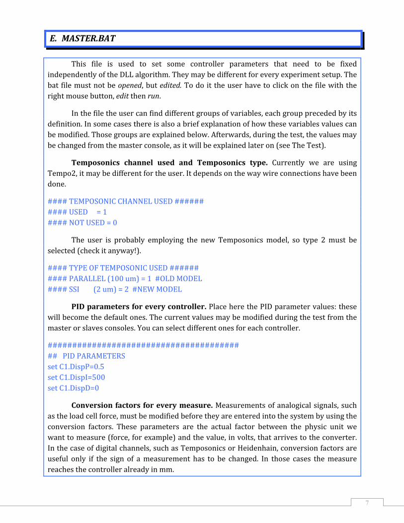
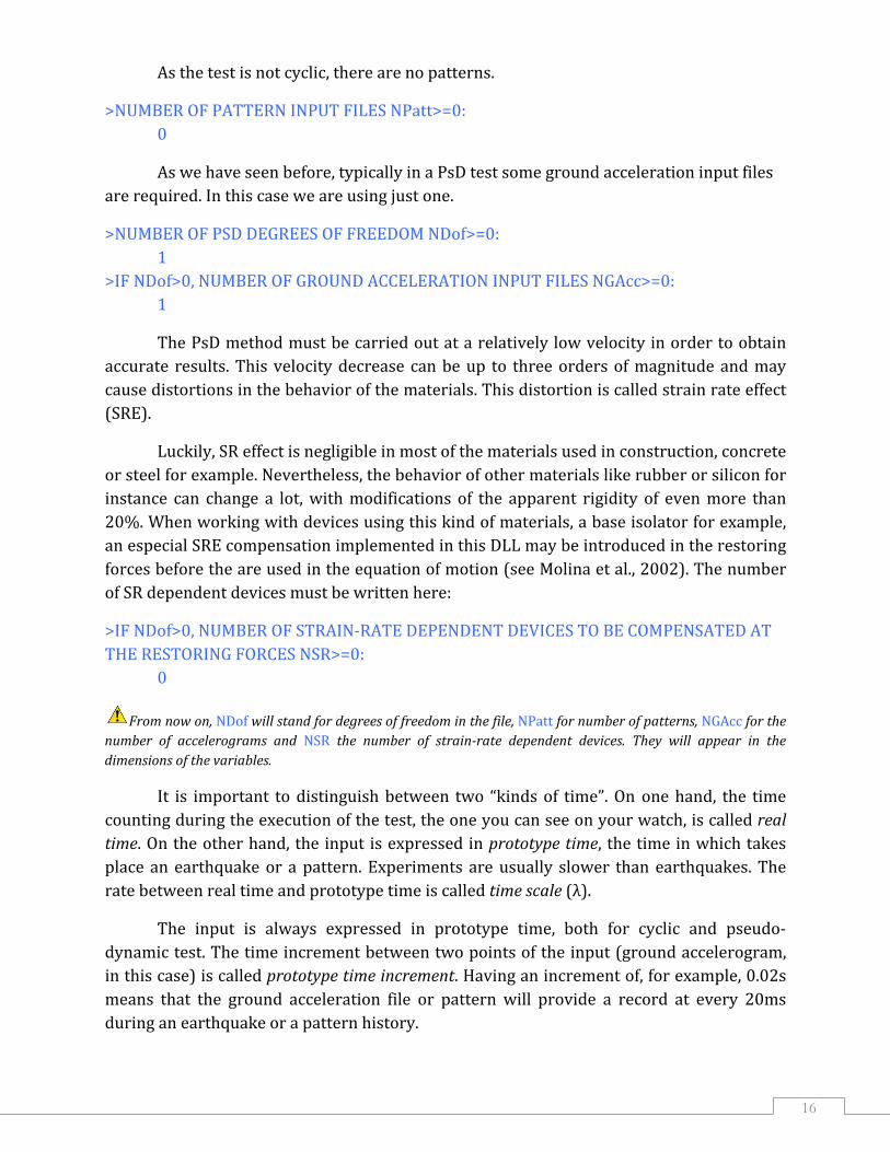
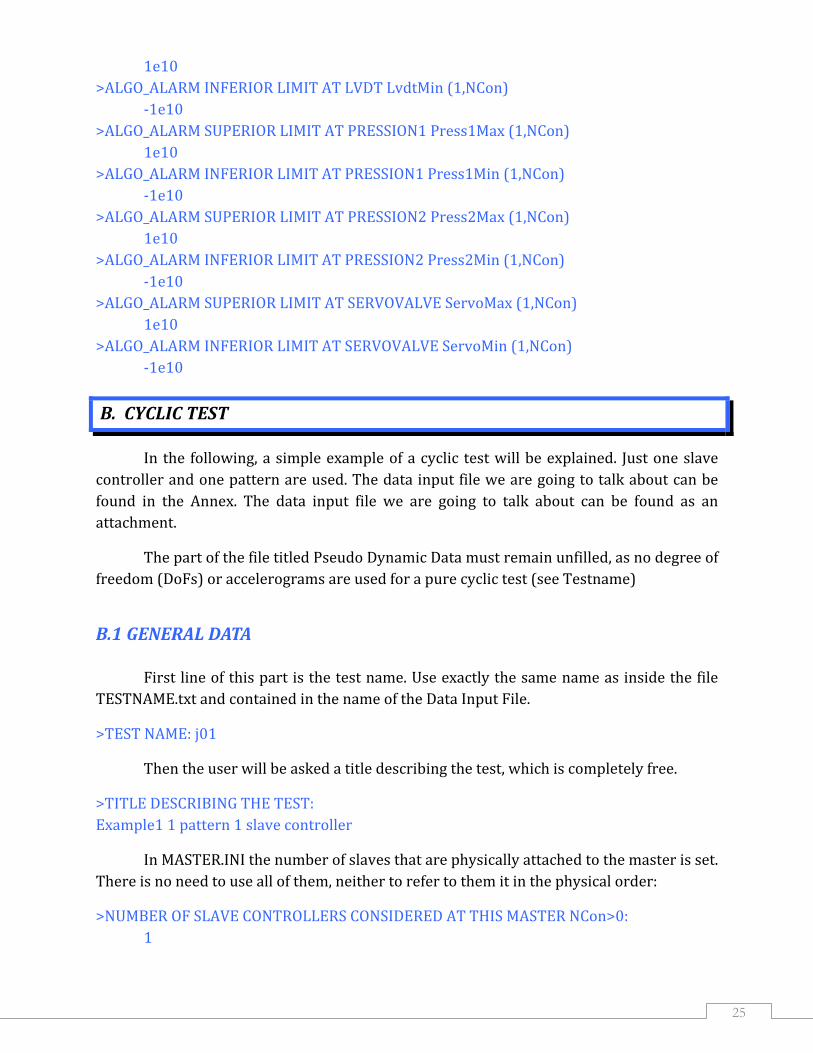
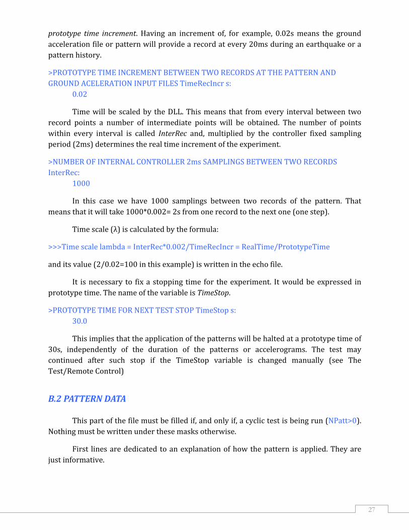

32
IV THE TEST
A TEST PROCEDURE
In this chapter a standard test procedure is going to be described It may change from one laboratory to another and from test to test but the conceptual aspects remain the ame s
Firstly the circulation pump must be started to allow the oil to get warm (30divide40⁰C) iAt this point there is st ll no pressure in the system
Now the files described on the previous chapter have to be loaded on the CMASTER folder of the master masterbat psdcyc03dll masterini testnametxt xxxx_dattxt and yyyy_patttxt or zzzz_acctxt depending on the kind of test Once the files have been loaded the master must be switched off and on in order to refresh the data
The master controller reads the files masterini and masterbat and starts to run the process masterDLLexe This process builds on the internal data base and then loads UserAlgorithimDLLdll
Note At this moment some problems could appear The most usual ones are The system cannot load the DLL the user must ensure that the name of the DLL is written properly on the masterbat file and that it has been loaded together with the other files The system gives no response at all the most usual reason is that the number of slaves exceed the one eflectedr in the masterini file
Once the DLL has been loaded the system starts reading the input data and creating the ECHO file which is a file containing the data the way the system is reading them The user should always check this file and also the parameters shown in the screen in order to avoid ldquomisunderstandingsrdquo with the computer If there is any line of the input data that is
stem will return an written in a wrong way the sy error like this
ERROR SHEARCHING FOR gtNUMBER OF SLAVE CONTROLLERS CONSIDERED AT THIS MASTER NCongt0 This is the line that should be written in the data input file
33
INCORRECT LINE SLAVE CONTROLLERS CONSIDERED AT THIS MASTER NCongt0 This d one is written instea
This will happen if any mask is modified a comment is written under a mask or something is written under a mask starting with an if when the condition is not
being fulfilled For example if the user is running a test in which no patterns are used the NPatt will be equal to zero and the system will give back an error if something is written under the mask
gtIF NPattgt0 PROPORTIONAL SPAN PERCENTAGE MULTIPILIER PattSpan (1NPatt)
After this first initialization phase the connection with the slave controllers together with the beginning of the interrupt sequence is activated by pressing the F12 key
e screenof the master (The user should see the values changing on th at this point)
At this moment the acquisitions on master and the acqnodes must be loaded sent nd staa rted (see Acquisition)
Now the variable selected for the control feedback must be chosen for every slave r controlle
Shift+H for Heidenhain control trol control
Shift+F for Load Cell conShift+T for Temposonicshift+LS for Lvdt control
The system is now ready for low pressure (around 30divide80 bar at ELSA) The feedback variable is then made zero by pressing F9 in every slave controller keyboard In the case of a non‐zero reference the slave controller will introduce the required offset to have anull error which is necessary before the next step
By doing F1 (toggle key) in every slave the servo valve and the PID algorithm are started launching the control process at the level of each slave Then the system can be put in high pressure mode (210 bar)
It is time now for changing the variable ErrorDelta to impose a thinner tolerance at the ErrorAlarm if required It can be done using the remote control or the command window as we will see later on Load cell forces must be zero at the beginning of the test To accomplish this offsetting the user must press F8 on every slave
If the initial reference is not zero (as for a restart test) the structure must be moved to that reference in order to have a null displacement or force offset To do so from the common controller command window at every slave (if the offset is equal for every slave) the user must utilize O or Shift O (apostrophe or shift apostrophe for more accuracy) The
34
use of the common controller command as well as the other capabilities of the master terfain ce will be explained more in detail later on
Even though the routine implementing the algorithm is already called at each interrupt from the moment the F12 key is pressed new target displacements are not yet issued to the slave controllers That is because the active part of the algorithm is prevented by an if‐then‐end‐if structure involving the F11 key As soon as the F11 key is pressed new target displacements are sent the forces are read and fed back to the master to compute the next step
During the test parameters can be changed using the remote control as we will see afterwards Pressing F11 key again will stop the test (if TimeStop has not been reached) Is time now for switching off all the pumps and stopping the acquisitions
B HOW TO COMMUNICATE WITH THE SYSTEM
The data exchange with the master is based on an internal database called AcqCtrlData This database consists of some memory blocks organized in several groups These memory blocks contain the definition and value of the signals key of the system They can be modified in the data input files before the test (see Data Input File) in real time via the console windows or the command windows (see The Test Users Interface) and via the remote control program installed on the remote station These memory blocks are exchanged to or from the master via a background process
B ERS INTERFACE COMMANDS AND SHORTCUTS
The master and every slave controller show in their screens a windows interface TAB is used for changing window and CTRL‐TAB for changing screen The mouse is not implemented Just one window is active at the time the active window has a blue caption bar These windows (see
1 US
Table 3) are described in this section
Master windows
Slave parameters Com nd mon controller comma
Command Computer information
Console Acquisition status Generator status Users parameters
Slave windows P arametersGraph 1 2 3 Command
35
Table 3 Master and slave windows
Parameters and graphs can be modified in two ways using a keyboard shortcut or typing a command on the console window
Figure 7 Master controller slave parameters common controller command and command
windows
Parameter window This window shows the most important parameters of the controller In the master screen there is one parameter window per slave in the so called controller slave parameter window while every slave shows its own one The physical slave controller number is displayed in the caption bar (see Figure 7 and Figure 8)
Note the numbering of the slaves within the DLL algorithm can be different if specified at the input file (see D ut File) ata Inp
The shortcuts that are going to be described below can be typed on any of the slaves keyboard when the parameter window is active for changing a parameter in that single slave The same effect will be obtained by typing those shortcuts on the master keyboard when the correspondent slave window is activeFor changing one of the parameters simultaneously in every slave the user must type the same shortcut in the master keyboard when the common controller command window is active in it Information about the PsD algorithm is displayed in this window the algorithm can be stopped or run using the key toggle F11 and alarms can be inserted or not via toggle key F10
Parameters are divided into several groups
36
First group is ALGO where the PID parameters are shown The user can change them wit cut SHIFT+h the short pid (increase)or SHIFT+pid (decrease)
The group MEASURE shows several measurements associated to every actuator DispshyH is the measure of the structural digital displacement transducer Heidenhain on the current controller given in mm Do SHIFT+h for selecting this measurement as feedback DispshyT is the measure of the actuator Temposonic displacement transducer on the current controller yalso in mm B doing SHIFT+t the user is selecting this measurement as feedback DispAbs is the absolute displacement of the piston usually measured by the Temposonic transducer It is expressed in mm DispshyL is the measure of an analogue displacement transducer such as Lvdt in mm It can be used as feedback by doing SHIFT+l Acc is the measurement of an accelerometer that can be eventually used on the specimen It is expressed in ms2 Speed is the measurement of a speed sensor in mms Press1 and Press2 are respectively the measurements of the pressure at the tension and the compression chambers of the piston expressed in bar The hardware is ready for admitting any these of variables in the control loop but this current version is not considering this possibility Force1 and Force2 are the measurements of two different load cells in kN applied to the y doing SHIFT+f piston Force1 is the piston load cell and can be used as feedback b
In the group REF (reference) the following parameters are shown Span ing from the in a multiplication factor applied to the target value commaster The user can modify it using the shortcut s SHIFT+s Error difference between the reference value and the feedback value Offset it span used to modify the offset added to the target the user can changemicrons by clicking o SHIFT+o or 2 microns by SHIFT+ldquo Alarm status of the error alarm (toggled by F4) written in red when active Level this is the value of the alarm level used by the error checking routine
The group SERVO appears only in the slaves screens Some information about the servovalve is presented in it ServoValve the voltage applied to the digital to analogue converter connected to the servo valve output of the PID algorithm Spool indicating the a return value of the spool displacement transducer in voltsaperture OnOff status of the ONOFF shut‐off valve toggled by the shortcut F1
The former shortcuts together with some other ones are summarized in the table 4 below
Note even though as we have seen before it is possible to use the F1 shortcut on the master and switch on every servovalve at once it is recommended to open one valve at a time In this way the user can ensure the stability of every piston before the opening of the next one servovalve This provides an additional security for the specimen
Figure 8 Slav m e para eters and command windows
Command window As we have seen before parameters and graphs can be modified either using the shortcuts on the keyboard or using the proper commands on the command window (see Figure 7 and Figure 8) Table 5 below shows the most usual ones
Note if you are using the master keyboard you will have to add the name of the memory block before the name of the variable
Set PSD1PDisp= 05
Information screen In this master screen general information about the system is shown name of the local computer IP address sampling timehellip
The console window is identical to the command window seen in the controller slave sc reen
The acquisition and generator status are also shown in another window of the information screen These windows support up to ten acquisition and generator objects crated in the master controller and they can be exchanged in the display by doing ALT+Tab
37
38
Figure 9 Master information screen
Command Shortcut
Only on the slave
Switch Screen CTRL‐TABSwitch View in Window ALT‐TABSwitch Window TABIncrease the scale of signal 1 at graph SHIFT 1Decrease the scale of signal 1 at graph 1Increase the scale of signal 2 at graph SHIFT+ 2Decrease the scale of signal 2 at graph 2
Increase P parameter SHIFT+ pDecrease P parameter pIncrease I parameter SHIFT+ iDecrease I parameter iIncrease D parameter SHIFT+ dDecrease D parameter dIncrease Offset of Span microns SHIFT+ oDecrease Offset of Span microns OIncrease Offset of 2 microns SHIFT+ lsquoDecrease Offset of 2 microns lsquoIncrease Span of 1 SHIFT+ sDecrease Span of 1 SOpen Close the servo valve F1 (see Note above)EnableDisable Alarm on Error F4
39
Command Shortcut
Only on the slave
Reset Lvdt Transducer to zero F5Reset Temposonics Transducer to zero F6Reset Heidenhain Transducer to zero F7Reset Force to zero F8
R sdeset Feedback Tran ucer F9
Only on the master DLL Algorithm Alarm InsertRemove F10DLL Algorithm ContinuePause F11
Set the Temposonic as feedback transducer SHIFT+ tSet the Heide as feedback transducer SHIFT+ hSet LVDT as feedback transducer SHIFT+ lSet Force1 as feedback transducer SHIFT+ F
Table 4 Command shortcut summary
If the user wants tohellip hellipthe command must be Change the value of a signal
Set [signSalName]=[value]et ErrorDelta=05
Get the value of a signal Get [signalName]Get CHANNEL_40
Graph a signal Graph [GraphNumber][SignalNumber][SignalName]
Graph 5 1 CHANNEL_40
Change a graph title Graph [GraphNumber]tit
Graph 3 tittlele[TitleString] Displacement
Change directory Cd [directory]List the directory Dir [directory]Display the content of the file
Type [filename]
Delete the file Del [filename]Copy file1 to file2 Copy [file1][file2]Rename the fithe name file2
le1 with
Rename [file1][file2]
Create a new subdirectory Mkdir [directory]
Remove the subdirectory if empty
Rmdir [directory]
Clean the screen Cls [directory]Load and execute command in the file
Load [filename]
Test TCPIP connection (only from the master)
Ping [IP address]
Table 5 Command summary
40
Figure 10 Master users parameters window
Users parameters screen This master screen is used by the algorithm DLL for displaying some variables and other information that is described below Some of these parameters values are selected by the user in the input text file see that section for more i about them nformation
Some sections of the screen change with the kind of experiment that is being carried out PsD cyclic or combined In the former case data related to the accelerogram employed as input and to the degrees of freedom is displayed In the case of a cyclic test pattern data are displayed Moreover when strain‐rate devices are used some information about them can be read on the screen If there are no SR devices a message in the upper part of the screen will inform of it
The first part of the screen is dedicated to some information given by the user name of the em d time for the nployed DLL name of the test an ext stop
The second part gives mostly instantaneous information The variables ending in _t come from the AL groupGO_T of memory of the DLL where their value is refreshed at every substep (2ms) iRec and Coun nd t_t The algorithm uses two counters one for the input records (iRec) aanother one for the internal steps within those records(Count_t) RunALgoshyF111 if the algorithm is running (the F11 key has been pressed) 2 if it is not TriggerInshyCH3 sometimes an external electrical switch on input channel 3 is used either to coordinate mo than one er or for are mast higher security In those cases a 1 is displayed when it is on and a 0 when it is not GAccSpan or PattSpan and PattISpan depending on the kind of experiment The span selected by the user in the input text file modifies the accelerogram or the pattern before it is used for the calculation of the target
InterRecIn is the number of internal substeps between two input records TimeInc s t time r i the time increment of the substep calcula ed by the algorithm as increment from one record point to the next one divided by the number of substeps Lambda is the time scale ratio between the real time and the prototype time It is calculated by the algorithm using the time duration of one step of the input In real time every substep lasts n the other hand in 2 ms that makes 2 times the number of substeps per step Oprototype time one step last one time increment Time_t is the prototype time seconds of pattern or of accelerogram Dis_t is the displac ed ement in meters calculated for of every degree of freedom consideron the specimen (DoF 1 DoF 2hellip) Res_t is the restoring force calculated for every degree of freedom It is expressed in N
41
Note the va triables of the equa ion of motion are expressed in the SI
Heid_t pressed in is the measure of the displacement transducer of every controller exmm LCell_t is the measure in kN of the load cell of every piston (Force 1 channel) Targe back t_t is the final target displacement or force depending on the selected feedcalculated for every piston It is expressed in mm or kN DSR_t r every SR device is the strain‐rate device displacement expressed in mm fo FSR_t is the SR device force in kN for every SR device EneAbs_t is the energy absorbed by the specimen expressed in J EneErr_t is the error energy calculated as the difference between the energy computed for isplacem the the target and the measured d ent
In the third section of the screen average information is displayed The variables ending in av come from the ALGOAV group of memory of the DLL where their value is calculated as the mean of the values of the previous record
The lower part of the screen is dedicated to the alarms (See Data Input File for further information)
B MOTE CONTROL VIEW AND MODIFICA ION OF VARIA LES
The remote control application can connect to the real time system via the IP address and retrieve all memories and signals information It is also possible to create
2 RE T B
acquisitions and generators objects with graphic interfaces (see Acquisition)
Once the remote control application has been started the connection with the master must be done The user has to introduce the IP number of the master and then press on the Connect button
Note it is recommended to close the Remote Control before shutting off the master and kill the orrespondent process (ACQCTRService) in the task manager c
42
Figure 11
A tree menu will appear with the voice Variables under the selected master By clicking on it the list of the different variables groups will be available Doing right click on each group without opening it gives the user the possibility to View the entire group of variables their names descriptions and values
Figure 12
Right clicking on every single variable on the tree menu gives the chance either to see the Voltmeter with the value of this variable or to Modify this value as it will be seen fterwaa rds
Among the several groups of variables there are some than may be more interesting for the user (see ELSA PSD Testing System)
PIDn where n is the number of actuator contains the PID parameters of the test read from the MASTERBAT file and eventually modified during the experiment Within this group the user can find
Displacement and force PID parameters (P I D) Span is a percentage factor that multiplies the reference before it arrives to the PID regulation A span of the 100 does not modify the reference
During the test the PID parameters are optimized for allowing the highest accuracy and velocity but they must be reduced in case of an undesired oscillation or a high feedback error In those cases it is important to react quickly avoiding damage on the structure The system is implemented with a safe mode which is a set of safe PID parameters decided by the user It is possible to apply it manually using a switch connected to the first in‐port of the slaves or changing the EnableSafePi variable value on the remote control program
43
Figure 13
MEASUREn the current measurements done on the structure such as DispH or DispT1 are collected in this group
Note The value of the variables in this block is not available to the acquisitions which should access the variables of the blocks INTERNALALGOINPUT and INTERNALALGOOUTPUT instead
MEASUREnshyCF group contains the value of the conversion factors for every measurement initially given to the system via the MASTERBAT file (see Master Con tion) figura
In the ALARMn group the user can find some information about the permitted error between reference and feedback such as
ErrorDelta is the maximum difference permitted between reference and feedback for the error alarm It is called level in the parameter window of the slave display
Inserted 0 when will be 1 when this alarm is inserted and it is not (F4 in the keyboard see users interface)
Status will be 0 if the error keeps beneath the given ErrorDelta and will change to 1 when it goes over
Repetition is the number of continuous alarms before the change of the status
44
Figure 14
Figure 15
Several antispike values (Tempo2 Heide Lvdt and Force1) can be found in the
ANTISPIKE group (see Data Input File for more information about antispike)
Figure 16 Figure 17
The PSD group gathers together some master application variables that interact with the DLL while runnin
g the test
bRunAlgo changes from 0 to 1 when the algorithm is running and is toggled by F11 at the master (see The TestTest Procedure)
bAlarmInsert e f aed ref rs to the set o alarms introduced by the DLL lgorithm (see also Data Input File) They are inserted by default at the beginning of the test and the user must ch void them (F10 key see users interface)
nds below the correspondent limit and wil ded
ange to 0 the value of this variable to a
bAlarmStatus will be zero while every variable remil change into 1 if any of the limits is excee is the name of the DLL used for the test DllAlgorithm
Figure 18
The from th
group ALGOUSERINPUT is created by the DLL and contains some parameters read e data input file or calculated by the algorithm
TestName and DLLName are read from the data input file just once at the beginning of the test and cannot been modified during it
TimeStop Int cSpan erRecIn Gac NFSamp and iRec are input variables read also from the data input file but can be modified from the remote control and their value will be applied at the beginning of the following step (see also Data Input File for more information about the variables meaning)
TimeLambda also called lambda is calculated by the algorithm at every step and its value is automatically refreshed with the new one so changing its value from the
45
46
remote control will have no effect Lambda is an informative variable used at thdisplay and not an input one
Note it is important to differentiate two types of alarms the feedback on error one and the DLL or ALGO one on
e
e checks e differenc reference a ack exceeds a det
very sampling time using the last ldquoaverage pointsrdquo
the algorithm an special proce
oup 4)Re‐launch the algorithm by pressing the F11 key
s The first if th e between nd feedb ermine limit and it may be able to stop the oil pumps if properly set The second one instead is a set of limits imposed to a group of DLL variables such as Heidenhain displacements or Load cell forces and it is able to stop only the DLL Algorithm in a reversible way
Groups ALGOR_T ALGORAv ALGORESTART and ALGORALARM correspond to the other four memory blocks created by the DLL The first one stores the instantaneous values f the uo sed variables while the second one stores the average values Within the third one some variables useful for the restart values can be found It may be interesting to view all those variables but not to change them as they are measurements (see Data Input File)
The variables of the ALGORAv group of memory are average values of the different measures calculated at the end of every record by the algorithm When running an acquisition it is possible to carry out an average computation on the rest of the memory blocks variables ALGOR_T for example by selecting an Average Points different from zero This averaging is done at the end of epoints of the sample (see Acquisition)
Figure 19
The fourth group contains the alarm limits for several variables read from the data input file (see Figure 20 below) Using the remote control is the most easy way for changing them durin d the user can change their value proce
g the test If none of the limits has been exceedeeding as in the other cases If the alarm has stoppeddure must be carried out to go on with the test
1) Avoid the algorithm by pressing the F11 key 2) Change the alarm status to 0 on the PSD group 3) Change the variable limit on the ALGORALARM gr
47
Figure 20
48
V INDEX AND REFERENCES
INDEX
I INTRODUCTION 1
II MASTER CONFIGURATION 4
A HOSTCFG
5
5
B USERCFG
6 C MASTERINI
XT 6 D TESTNAMET
7 E MASTERBAT
F ATA FILES 10 EXCITATION‐HISTORY INPUT D
LERATION FILE 10 F1 GROUND ACCE
F2 PATTERN FILE 11
III DATA INPUT FILE 13
A IC TEST 15 PSEUDO‐DYNAM
15 A1 GENERAL DATA
ATRICES 17 A2 OTHER INFLUENCE M
18 A3 PsD EQUATION DATA
NDENT DEVICES 22 A4 STRAIN RATE DEPE
A5 ALGO ALARM DATA 23
B 25 CYCLIC TEST
25 B1 GENERAL DATA
27 B2 PATTERN DATA
B3 OTHER INFLUENCE MATRICES 29
49
B4 ALGO ALARM DATA 30
IV THE TEST 32
A TEST PROCEDURE
B 34
32
HOW TO COMMUNICATE WITH THE SYSTEM
34 B1 USERS INTERFACE COMMANDS AND SHORTCUTS
B2 REMOTE CONTROL VIEW AND MODIFICATION OF VARIABLES 41
REFERENCES
F J Molina G Verzeletti G Magonette Ph Buchet V Renda M Geradin A Parducci M Mezzi A Pacchiarotti L Federici and S Mascelloni lsquoPseudodynamic tests on rubber base isolators with numerical substructuring of the superstructure and strain‐rate effect compensationrsquo Earthquake Engineering amp Structural Dynamics Vol 31 1563‐1582 (2002)
Elsa PSD Testing System Philippe Buchet ELSA Laboratory Joint Research Centre Ispra Italy (2004)
Acquisition User Manual Beatriz Zapico Blanco F Javier Molina ELSA Laboratory Joint Research Centre Ispra Italy (2008)
European Commission EUR 23448 EN ndash Joint Research Centre ndash Institute for the Protection and Security of the Citizen Title PSDCYC03DLL User Manual Author(s) Beatriz Zapico Blanco FJavier Molina Luxembourg Office for Official Publications of the European Communities 2008 ndash 49 pp ndash 21 x 297 cm EUR ndash Scientific and Technical Research series ndash ISSN 1018-5593 ISBN 978-92-79-09120-9 DOI 10278887951 Abstract A DLL (Dynamic Link Library) is a file of code containing functions that can be called from other executable code The advantage of working with DLLs at ELSA PsD Master controller is in the modularity for programming the testing method and algorithm without the need to work with the masterexe program This new version of DLL allows the implementation of both PsD and Cyclic test plus strain-rate effect compensation re-start capabilities and a large variety of security alarms In this manual the user will find a full explanation of how to use the DLL throughout some simple examples Some other examples coming from real tests carried out at ELSA laboratory can be found in the Annex
How to obtain EU publications Our priced publications are available from EU Bookshop (httpbookshopeuropaeu) where you can place an order with the sales agent of your choice The Publications Office has a worldwide network of sales agents You can obtain their contact details by sending a fax to (352) 29 29-42758
The mission of the JRC is to provide customer-driven scientific and technical supportfor the conception development implementation and monitoring of EU policies As a service of the European Commission the JRC functions as a reference centre of science and technology for the Union Close to the policy-making process it serves the common interest of the Member States while being independent of special interests whether private or national
LB
-NA
-23448-EN-C
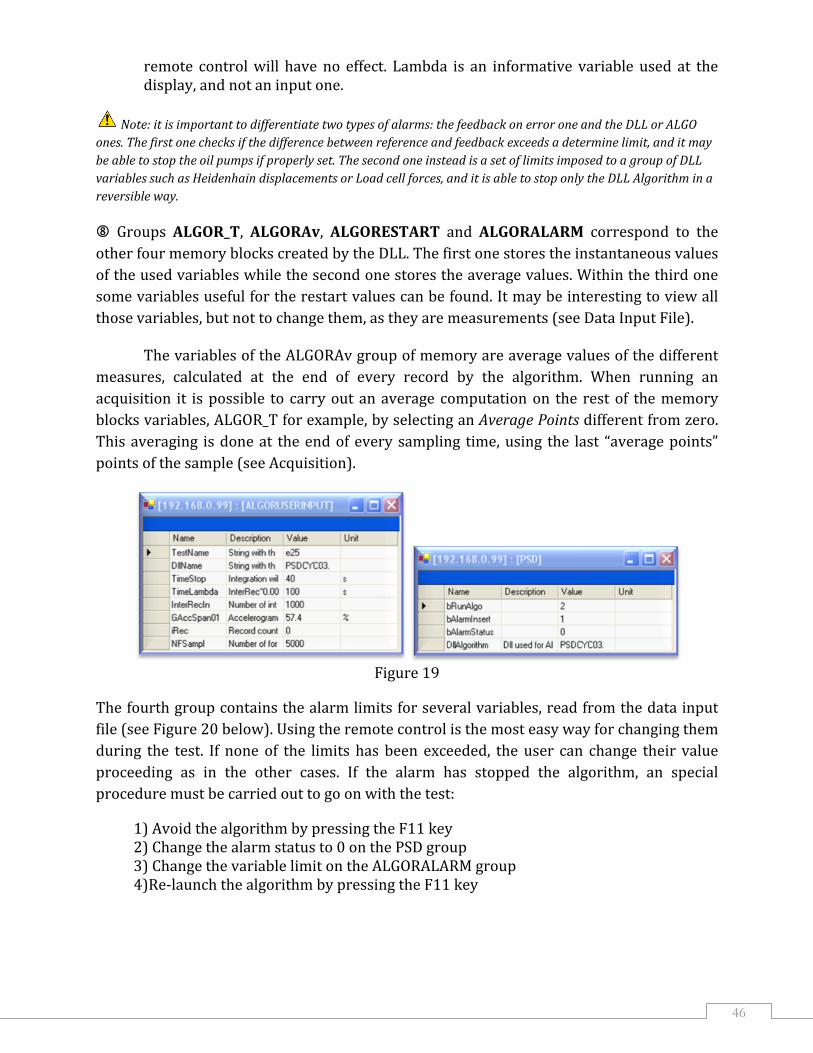