Embed Size (px)
Citation preview
www.tridonic.com 1Subject to change without notice.
Data sheet 01/19-EM070-6
Emergency lighting units
EM converterLED
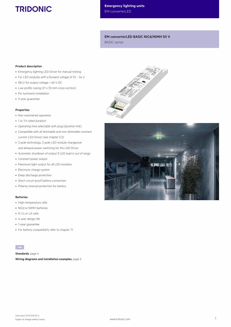
Product description
• Emergency lighting LED Driver for manual testing
• For LED modules with a forward voltage of 10 – 54 V
• SELV for output voltage < 60 V DC
• Low profile casing (21 x 30 mm cross-section)
• For luminaire installation
• 5-year guarantee
Properties
• Non maintained operation
• 1 or 3 h rated duration
• Operating time selectable with plug (duration link)
• Compatible with all dimmable and non-dimmable constant
current LED Driver (see chapter 5.3)
• 3-pole technology: 2-pole LED module changeover
and delayed power switching for the LED Driver
• Automatic shutdown of output if LED load is out of range
• Constant power output
• Maximum light output for all LED modules
• Electronic charge system
• Deep discharge protection
• Short-circuit-proof battery connection
• Polarity reversal protection for battery
Batteries
• High-temperature cells
• NiCd or NiMH batteries
• D, Cs or LA cells
• 4-year design life
• 1-year guarantee
• For battery compatibility refer to chapter 7.1
ÈStandards, page 4
Wiring diagrams and installation examples, page 5
EM converterLED BASIC NiCd/NiMH 50 V
BASIC series
www.tridonic.com 2Subject to change without notice.
Data sheet 01/19-EM070-6
Emergency lighting units
EM converterLED
Status indication green LED
ACC
ES-
SOR
IES
Test switch EM3
ACC
ES-
SOR
IES
Ordering data
Type Article numberPackaging, bag
Packaging,carton
Weight per pc.
Test switch EM 3 89899956 25 pc(s). 200 pc(s). 0.013 kg
Specific technical data
Type2 Rated durationTyp. output
powerMains current in charging operation Rated power in charging operation
Initial charge Fast recharge Trickle charge Initial charge Fast recharge Trickle charge
EM converterLED BASIC 202 NiCd/NiMH 50V 1 h 1.5 W 16 mA 16 mA 14 mA 2.2 W 2.2 W 1.6 W
3 h 1.5 W 20 mA 20 mA 15 mA 3.0 W 3.0 W 2.2 W
EM converterLED BASIC 203 NiCd/NiMH 50V 1 h 2.4 W 17 mA 17 mA 16 mA 2.3 W 2.3 W 1.7 W
3 h 2.4 W 22 mA 22 mA 18 mA 3.4 W 3.4 W 2.3 W
EM converterLED BASIC 204 NiCd/NiMH 50V1 h 3.5 W 19 mA 19 mA 15 mA 2.7 W 2.7 W 1.7 W
3 h 3.5 W 25 mA 25 mA 19 mA 3.9 W 3.9 W 2.7 W1 16 h battery charging time for 2 h emergency lighting function according to AS 2293.2 EM = Emergency
EM converterLED BASIC NiCd/NiMH 50 V
BASIC series
30
2130
179
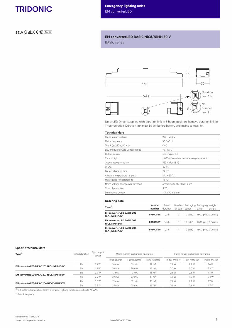
169.2Durationlink 3 h
No durationlink 1 h
Note: LED Driver supplied with duration link in 3 hours position. Remove duration link for 1 hour duration. Duration link must be set before battery and mains connection.
Technical dataRated supply voltage 220 – 240 V
Mains frequency 50 / 60 Hz
Typ. λ (at 230 V, 50 Hz) 0.6C
LED module forward voltage range 10 – 54 V
Output current see chapter 5.2
Time to light < 0.25 s from detection of emergency event
Overvoltage protection 320 V (for 48 h)
U-OUT 60 V
Battery charging time 24 h1
Ambient temperature range ta -5 ... + 55 °C
Max. casing temperature tc 75 °C
Mains voltage changeover threshold according to EN 60598-2-22
Type of protection IP20
Dimensions LxWxH 179 x 30 x 21 mm
Ordering data
Type2 Article number
Rated duration
Number of cells
Packaging, carton
Packaging, pallet
Weight per pc.
EM converterLED BASIC 202 NiCd/NiMH 50V
89800558 1/3 h 2 10 pc(s). 1,600 pc(s).0.065 kg
EM converterLED BASIC 203 NiCd/NiMH 50V
89800559 1/3 h 3 10 pc(s). 1,600 pc(s).0.065 kg
EM converterLED BASIC 204 NiCd/NiMH 50V
89800560 1/3 h 4 10 pc(s). 1,600 pc(s).0.065 kg
www.tridonic.com 3Subject to change without notice.
Data sheet 01/19-EM070-6
Emergency lighting units
EM converterLED
Product description
• A green LED indicates that charging current is flowing into the
battery
• Plug connection
Status indication green LED
ACC
ES-
SOR
IES
Ordering data
Type Article numberPackaging, bag
Packaging, carton
Weight per pc.
LED EM green, 1.0 m CON 89800269 25 pc(s). 200 pc(s). 0.015 kg
LED EM green, HO 1.0 m CON 89800271 25 pc(s). 200 pc(s). 0.015 kg
LED EM green, 0.6 m CON 89800472 25 pc(s). 200 pc(s). 0.009 kg
LED EM green, HO 0.6 m CON 89800473 25 pc(s). 200 pc(s). 0.009 kg
LED EM green, 0.3 m CON 89800270 25 pc(s). 200 pc(s). 0.005 kg
LED EM green, HO 0.3 m CON 89800272 25 pc(s). 200 pc(s). 0.005 kg
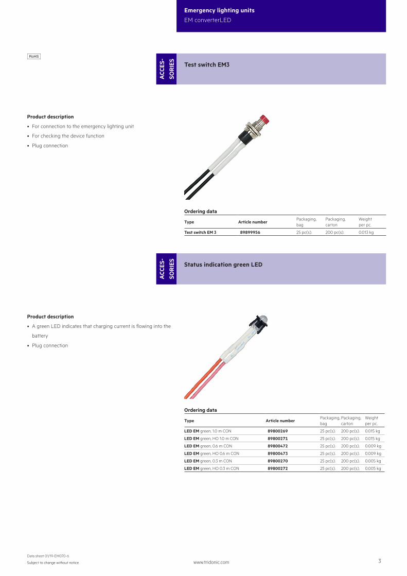
Product description
• For connection to the emergency lighting unit
• For checking the device function
• Plug connection
Test switch EM3
ACC
ES-
SOR
IES
Ordering data
Type Article numberPackaging, bag
Packaging,carton
Weight per pc.
Test switch EM 3 89899956 25 pc(s). 200 pc(s). 0.013 kg
EM converterLED BASIC NiCd 50 V
BASIC series
30
2130
179
169.2Durationlink 3 h
No durationlink 1 h
Note: LED Driver supplied with duration link in 3 hours position. Remove duration link for 1 hour duration. Duration link must be set before battery and mains connection.
Technical dataRated supply voltage 220 – 240 V
Mains frequency 50 / 60 Hz
Typ. λ (at 230 V, 50 Hz) 0.7
LED module forward voltage range 10 – 54 V
Output current see chapter 5.2
Time to light < 0.25 s from detection of emergency event
Overvoltage protection 320 V (for 48 h)
U-OUT 60 V
Battery charging time 24 h1
Ambient temperature range ta -5 ... + 55 °C
Max. casing temperature tc 75 °C
Mains voltage changeover threshold according to EN 60598-2-22
Type of protection IP20
Dimensions LxWxH 179 x 30 x 21 mm
Ordering data
Type2 Article number
Rated duration
Number of cells
Packaging, carton
Packaging, pallet
Weight per pc.
EM converterLED BASIC 202 NiCd 50V
89800558 1/3 h 2 10 pc(s). 1,600 pc(s).0.065 kg
EM converterLED BASIC 203 NiCd 50V
89800559 1/3 h 3 10 pc(s). 1,600 pc(s).0.065 kg
EM converterLED BASIC 204 NiCd 50V
89800560 1/3 h 4 10 pc(s). 1,600 pc(s).0.065 kg
www.tridonic.com 4Subject to change without notice.
Data sheet 01/19-EM070-6
Emergency lighting units
EM converterLED
1. Standards
• EN 61347-1• EN 61347-2-13• EN 61347-2-7• EN 55015• EN 61000-3-2• EN 61000-3-3• EN 61547• EN 60068-2-64• EN 60068-2-29• EN 60068-2-30• EN 62384• according to EN 50172• according to EN 60598-2-22
1.1 Glow-wire test
according to EN 61347-1 with increased temperature of 850 °C passed.
1.2 Isolation and electric strength testing of luminaires
Electronic LED-Drivers can be damaged by high voltage. This has to be consid-ered during the routine testing of the luminaires in production.
According to IEC 60598-1 Annex Q (informative only!) or ENEC 303-Annex A, each luminaire should be submitted to an isolation test with 500 VDC for 1 sec-ond. This test voltage should be connected between the interconnected phase and neutral terminals and the earth terminal. The isolation resistance must be at least 2 MΩ.
As an alternative, IEC 60598-1 Annex Q describes a test of the electrical strength with 1,500 VAC (or 1,414 x 1,500 VDC). To avoid damage to the electronic devices this test must not be conducted.
2. Thermal details and life-time
2.1 Life-time
Average life-time 50,000 hours under rated conditions with a failure rate of less than 10 %. Average failure rate of 0.2 % per 1000 operating hours.
Expected life-time
Type ta 40 °C 50 °C 55 °C
EM converterLED BASIC 202 NiCd/NiMH 50V tc 65 °C 70 °C 75 °C
life-time > 100,000 h 97,000 h 69,000 h
EM converterLED BASIC 203 NiCd/NiMH 50Vtc 65 °C 70 °C 75 °C
life-time > 100,000 h 92,000 h 65,000 h
EM converterLED BASIC 204 NiCd/NiMH 50V tc 65 °C 70 °C 75 °C
life-time > 100,000 h 78,000 h 55,000 h
3. Installation / Wiring
3.1 Wiring diagram
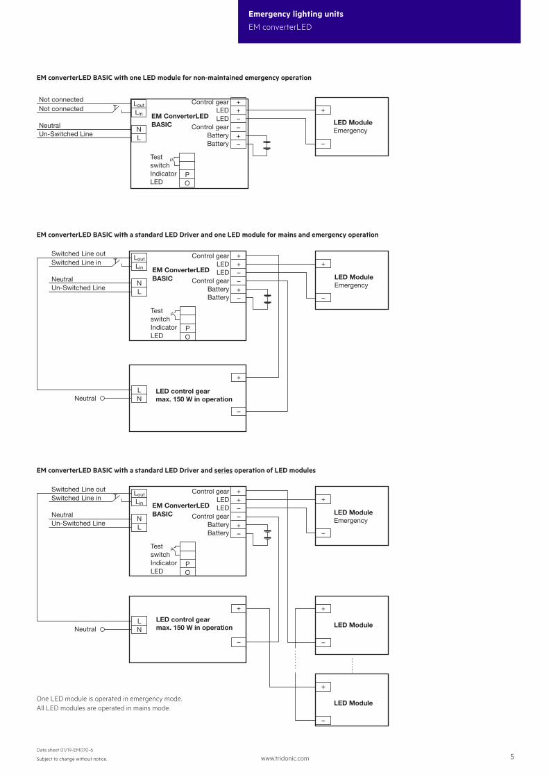
One or more LED modules with a total forward voltage of 10 to 54 V can be con-nected to the EM converterLED 50V module. These LED module(s), marked with “Emergency” are operated in emergency mode from the associated battery. In normal mains mode all LED modules are operated by the LED Driver from the mains supply.
Use of the test switch: For checking the device function press the test switch for a minimum of 3 seconds.
www.tridonic.com 5Subject to change without notice.
Data sheet 01/19-EM070-6
Emergency lighting units
EM converterLED
EM converterLED BASIC with a standard LED Driver and one LED module for mains and emergency operation
Neutral
++––+– –
+
PO
LoutLin
NL
LN
NeutralUn-Switched Line
TestswitchIndicatorLED
Switched Line inSwitched Line out Control gear
LEDLED
Control gearBatteryBattery
LED ModuleEmergency
–
+
LED control gearmax. 150 W in operation
EM ConverterLEDBASIC
EM converterLED BASIC with one LED module for non-maintained emergency operation
++––+– –
+
PO
LoutLin
NL
EM ConverterLEDBASICNeutral
Un-Switched Line
TestswitchIndicatorLED
Not connectedNot connected Control gear
LEDLED
Control gearBatteryBattery
LED ModuleEmergency
EM converterLED BASIC with a standard LED Driver and series operation of LED modules
One LED module is operated in emergency mode.All LED modules are operated in mains mode.
Neutral
++––+– –
+
PO
LoutLin
NL
LN
NeutralUn-Switched Line
TestswitchIndicatorLED
Switched Line inSwitched Line out Control gear
LEDLED
Control gearBatteryBattery
LED ModuleEmergency
–
+
–
+
LED Module
–
+
LED ModuleLED control gearmax. 150 W in operation
EM ConverterLEDBASIC
www.tridonic.com 6Subject to change without notice.
Data sheet 01/19-EM070-6
Emergency lighting units
EM converterLED
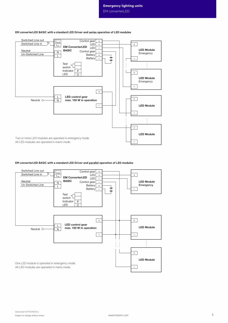
EM converterLED BASIC with a standard LED Driver and series operation of LED modules
Neutral
++––+– –
+
PO
LoutLin
NL
LN
NeutralUn-Switched Line
TestswitchIndicatorLED
Control gearLEDLED
Control gearBatteryBattery
LED ModuleEmergency
–
+
–
+
LED Module
LED control gearmax. 150 W in operation
–
+
LED ModuleEmergency
–
+
LED Module
Switched Line inSwitched Line out
EM ConverterLEDBASIC
Two or more LED modules are operated in emergency mode.All LED modules are operated in mains mode.
EM converterLED BASIC with a standard LED Driver and parallel operation of LED modules
Neutral
++––+– –
+
PO
LoutLin
NL
LN
NeutralUn-Switched Line
TestswitchIndicatorLED
Control gearLEDLED
Control gearBatteryBattery
LED ModuleEmergency
–
+
–
+
LED Module
–
+
LED ModuleLED control gearmax. 150 W in operation
Switched Line inSwitched Line out
EM ConverterLEDBASIC
One LED module is operated in emergency mode.All LED modules are operated in mains mode.
www.tridonic.com 7Subject to change without notice.
Data sheet 01/19-EM070-6
Emergency lighting units
EM converterLED
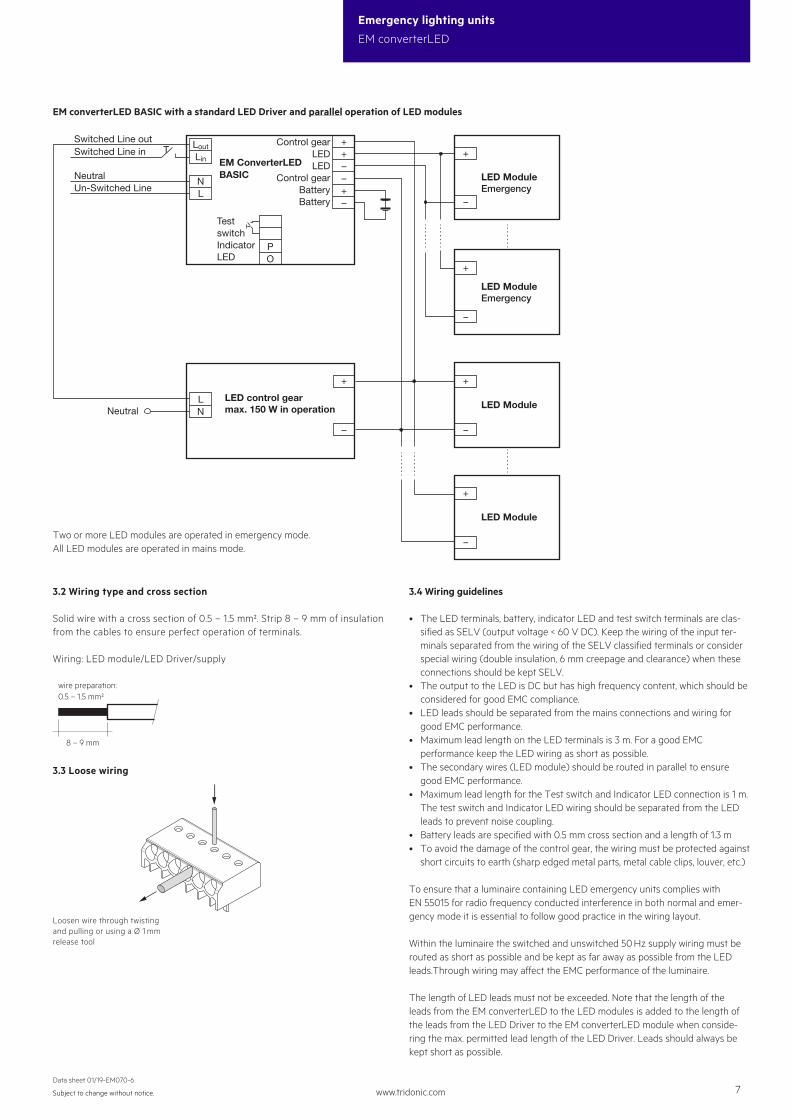
EM converterLED BASIC with a standard LED Driver and parallel operation of LED modules
Neutral
++––+– –
+
PO
LoutLin
NL
LN
NeutralUn-Switched Line
TestswitchIndicatorLED
Control gearLEDLED
Control gearBatteryBattery
LED ModuleEmergency
LED ModuleEmergency
–
+
–
+
LED Module
–
+
LED ModuleLED control gearmax. 150 W in operation
–
+
Switched Line inSwitched Line out
EM ConverterLEDBASIC
Two or more LED modules are operated in emergency mode.All LED modules are operated in mains mode.
3.3 Loose wiring
8 – 9 mm
wire preparation:0.5 – 1.5 mm²
3.2 Wiring type and cross section
Solid wire with a cross section of 0.5 – 1.5 mm². Strip 8 – 9 mm of insulationfrom the cables to ensure perfect operation of terminals.
Wiring: LED module/LED Driver/supply
Loosen wire through twisting and pulling or using a Ø 1 mm release tool
3.4 Wiring guidelines
• The LED terminals, battery, indicator LED and test switch terminals are clas-sified as SELV (output voltage < 60 V DC). Keep the wiring of the input ter-minals separated from the wiring of the SELV classified terminals or consider special wiring (double insulation, 6 mm creepage and clearance) when these connections should be kept SELV.
• The output to the LED is DC but has high frequency content, which should be considered for good EMC compliance.
• LED leads should be separated from the mains connections and wiring for good EMC performance.
• Maximum lead length on the LED terminals is 3 m. For a good EMC performance keep the LED wiring as short as possible.
• The secondary wires (LED module) should be routed in parallel to ensure good EMC performance.
• Maximum lead length for the Test switch and Indicator LED connection is 1 m. The test switch and Indicator LED wiring should be separated from the LED leads to prevent noise coupling.
• Battery leads are specified with 0.5 mm cross section and a length of 1.3 m• To avoid the damage of the control gear, the wiring must be protected against
short circuits to earth (sharp edged metal parts, metal cable clips, louver, etc.)
To ensure that a luminaire containing LED emergency units complies with EN 55015 for radio frequency conducted interference in both normal and emer-gency mode it is essential to follow good practice in the wiring layout.
Within the luminaire the switched and unswitched 50 Hz supply wiring must be routed as short as possible and be kept as far away as possible from the LED leads.Through wiring may affect the EMC performance of the luminaire.
The length of LED leads must not be exceeded. Note that the length of the leads from the EM converterLED to the LED modules is added to the length of the leads from the LED Driver to the EM converterLED module when conside-ring the max. permitted lead length of the LED Driver. Leads should always be kept short as possible.
www.tridonic.com 8Subject to change without notice.
Data sheet 01/19-EM070-6
Emergency lighting units
EM converterLED
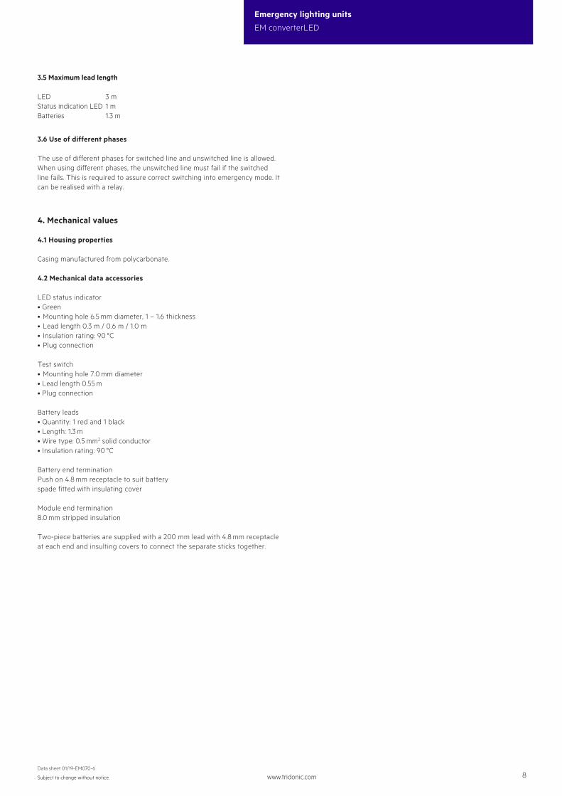
4. Mechanical values
4.1 Housing properties
Casing manufactured from polycarbonate.
4.2 Mechanical data accessories
LED status indicator• Green• Mounting hole 6.5 mm diameter, 1 – 1.6 thickness• Lead length 0.3 m / 0.6 m / 1.0 m• Insulation rating: 90 °C• Plug connection
Test switch• Mounting hole 7.0 mm diameter• Lead length 0.55 m• Plug connection
Battery leads• Quantity: 1 red and 1 black• Length: 1.3 m• Wire type: 0.5 mm2 solid conductor• Insulation rating: 90 °C
Battery end terminationPush on 4.8 mm receptacle to suit batteryspade fitted with insulating cover
Module end termination8.0 mm stripped insulation
Two-piece batteries are supplied with a 200 mm lead with 4.8 mm receptacle at each end and insulting covers to connect the separate sticks together.
3.5 Maximum lead length
LED 3 mStatus indication LED 1 mBatteries 1.3 m
3.6 Use of different phases
The use of different phases for switched line and unswitched line is allowed. When using different phases, the unswitched line must fail if the switched line fails. This is required to assure correct switching into emergency mode. It can be realised with a relay.
www.tridonic.com 9Subject to change without notice.
Data sheet 01/19-EM070-6
Emergency lighting units
EM converterLED
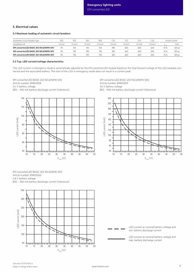
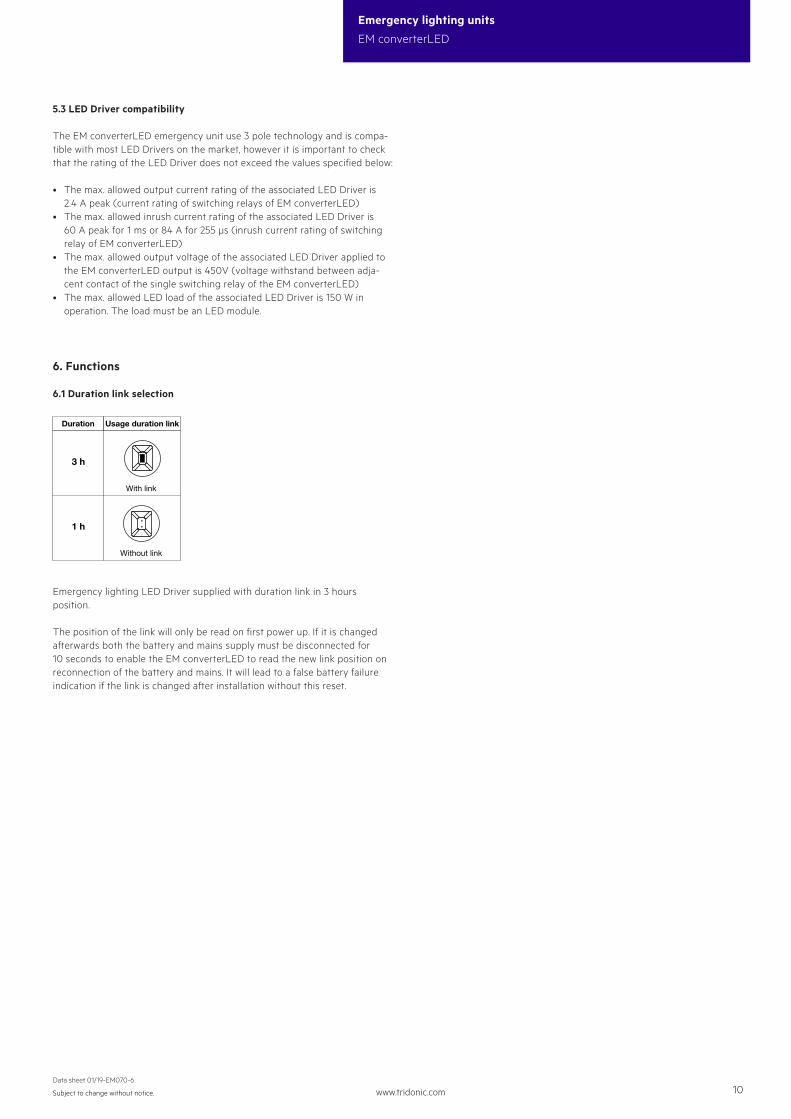
5. Electrical values
5.1 Maximum loading of automatic circuit breakers
Automatic circuit breaker type B10 B13 B16 B20 C10 C13 C16 C20 Inrush current
Installation Ø 1.5 mm2 1.5 mm2 1.5 mm2 2.5 mm2 1.5 mm2 1.5 mm2 1.5 mm2 2.5 mm2 Imax
time
EM converterLED BASIC 202 NiCd/NiMH 50V 90 130 130 130 180 260 260 260 10 A 120 μs
EM converterLED BASIC 203 NiCd/NiMH 50V 90 130 130 130 180 260 260 260 10 A 120 μs
EM converterLED BASIC 204 NiCd/NiMH 50V 90 130 130 130 180 260 260 260 10 A 120 μs
5.2 Typ. LED current/voltage characteristics
The LED current in emergency mode is automatically adjusted by the EM converterLED module based on the total forward voltage of the LED modules con-nected and the associated battery. The start of the LED in emergency mode does not result in a current peak.
EM converterLED BASIC 202 NiCd/NiMH 50VArticle number: 898005582.4 V battery voltage850 – 960 mA battery discharge current (tolerance)
EM converterLED BASIC 203 NiCd/NiMH 50VArticle number: 898005593.6 V battery voltage850 – 960 mA battery discharge current (tolerance)
LED
cur
rent
[mA
]
VLED
[V] VLED
[V]
LED
cur
rent
[mA
]
10 2015 25 35 4530 40 50 55
80
60
140
120
100
40
220
200
180
160
240
10 2015 25 35 4530 40 50 55
40
60
80
20
120
100
140
EM converterLED BASIC 204 NiCd/NiMH 50VArticle number: 898005604.8 V battery voltage850 – 960 mA battery discharge current (tolerance)
10 2015 25 35 4530 40 50 55
100
150
200
250
300
50
350
LED
cur
rent
[mA
]
VLED
[V]
LED current at nominal battery voltage and min. battery discharge current
LED current at nominal battery voltage and max. battery discharge current
www.tridonic.com 10Subject to change without notice.
Data sheet 01/19-EM070-6
Emergency lighting units
EM converterLED
5.3 LED Driver compatibility
The EM converterLED emergency unit use 3 pole technology and is compa-tible with most LED Drivers on the market, however it is important to check that the rating of the LED Driver does not exceed the values specified below:
• The max. allowed output current rating of the associated LED Driver is 2.4 A peak (current rating of switching relays of EM converterLED)
• The max. allowed inrush current rating of the associated LED Driver is 60 A peak for 1 ms or 84 A for 255 μs (inrush current rating of switching relay of EM converterLED)
• The max. allowed output voltage of the associated LED Driver applied to the EM converterLED output is 450V (voltage withstand between adja-cent contact of the single switching relay of the EM converterLED)
• The max. allowed LED load of the associated LED Driver is 150 W in operation. The load must be an LED module.
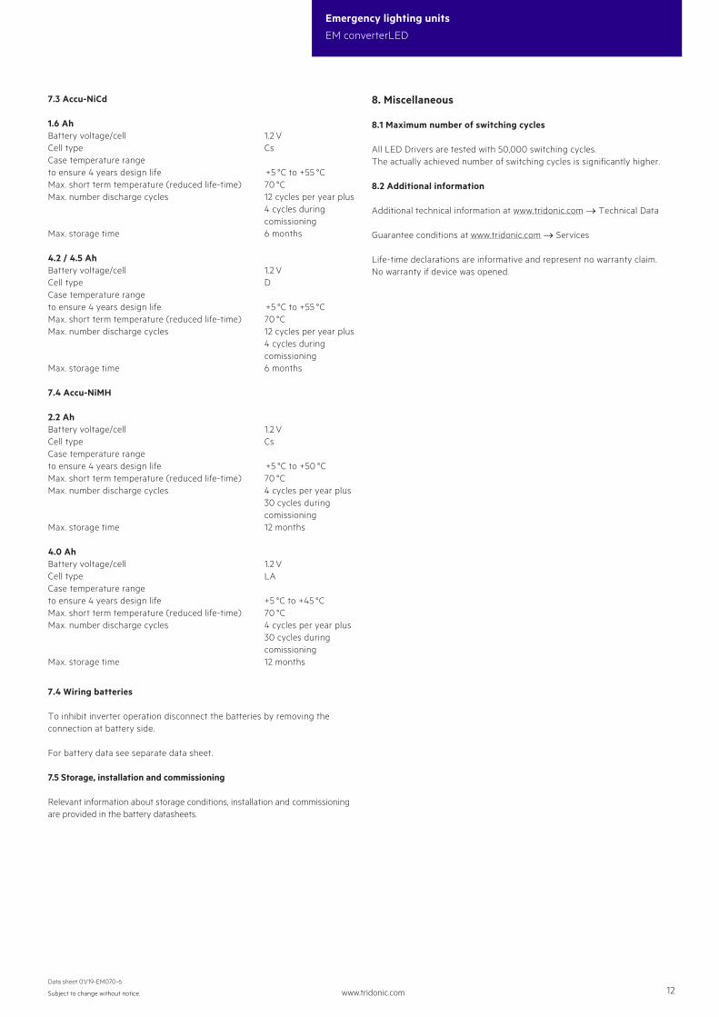
6. Functions
6.1 Duration link selection
1 h
3 h
Without link
With link
Duration Usage duration link
Emergency lighting LED Driver supplied with duration link in 3 hours position.
The position of the link will only be read on first power up. If it is changed afterwards both the battery and mains supply must be disconnected for 10 seconds to enable the EM converterLED to read the new link position on reconnection of the battery and mains. It will lead to a false battery failure indication if the link is changed after installation without this reset.
www.tridonic.com 11Subject to change without notice.
Data sheet 01/19-EM070-6
Emergency lighting units
EM converterLED
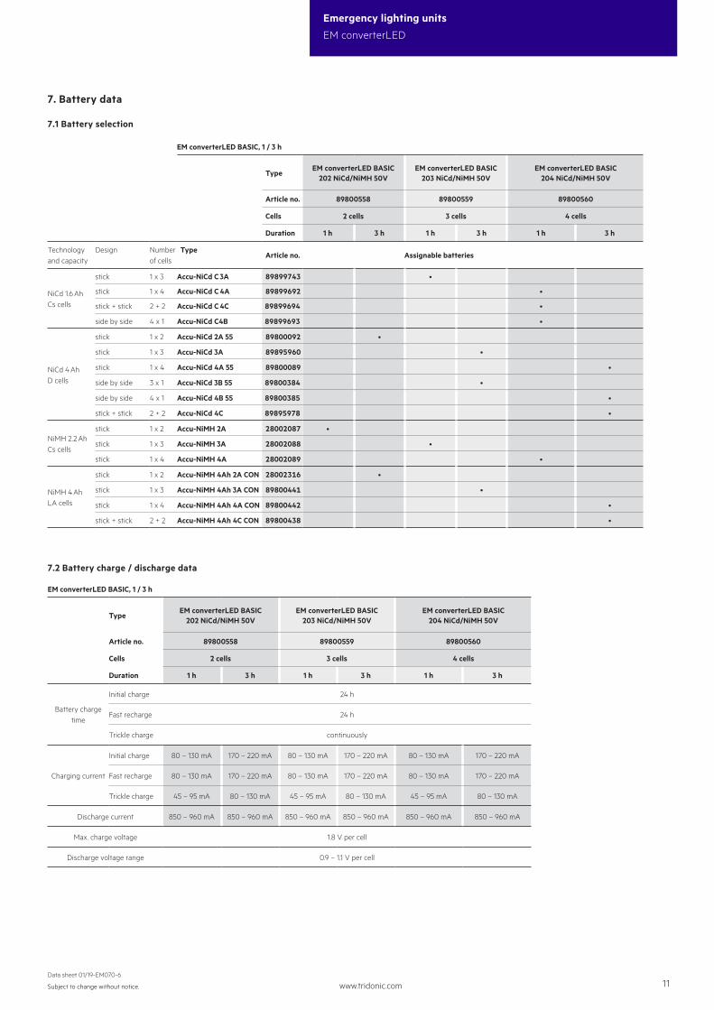
EM converterLED BASIC, 1 / 3 h
TypeEM converterLED BASIC
202 NiCd/NiMH 50VEM converterLED BASIC
203 NiCd/NiMH 50VEM converterLED BASIC
204 NiCd/NiMH 50V
Article no. 89800558 89800559 89800560
Cells 2 cells 3 cells 4 cells
Duration 1 h 3 h 1 h 3 h 1 h 3 h
Technology and capacity
Design Number of cells
TypeArticle no. Assignable batteries
NiCd 1.6 Ah Cs cells
stick 1 x 3 Accu-NiCd C 3A 89899743 •
stick 1 x 4 Accu-NiCd C 4A 89899692 •
stick + stick 2 + 2 Accu-NiCd C 4C 89899694 •
side by side 4 x 1 Accu-NiCd C4B 89899693 •
NiCd 4 Ah D cells
stick 1 x 2 Accu-NiCd 2A 55 89800092 •
stick 1 x 3 Accu-NiCd 3A 89895960 •
stick 1 x 4 Accu-NiCd 4A 55 89800089 •
side by side 3 x 1 Accu-NiCd 3B 55 89800384 •
side by side 4 x 1 Accu-NiCd 4B 55 89800385 •
stick + stick 2 + 2 Accu-NiCd 4C 89895978 •
NiMH 2.2 Ah Cs cells
stick 1 x 2 Accu-NiMH 2A 28002087 •
stick 1 x 3 Accu-NiMH 3A 28002088 •
stick 1 x 4 Accu-NiMH 4A 28002089 •
NiMH 4 Ah LA cells
stick 1 x 2 Accu-NiMH 4Ah 2A CON 28002316 •
stick 1 x 3 Accu-NiMH 4Ah 3A CON 89800441 •
stick 1 x 4 Accu-NiMH 4Ah 4A CON 89800442 •
stick + stick 2 + 2 Accu-NiMH 4Ah 4C CON 89800438 •
EM converterLED BASIC, 1 / 3 h
TypeEM converterLED BASIC
202 NiCd/NiMH 50VEM converterLED BASIC
203 NiCd/NiMH 50VEM converterLED BASIC
204 NiCd/NiMH 50V
Article no. 89800558 89800559 89800560
Cells 2 cells 3 cells 4 cells
Duration 1 h 3 h 1 h 3 h 1 h 3 h
Battery charge time
Initial charge 24 h
Fast recharge 24 h
Trickle charge continuously
Charging current
Initial charge 80 – 130 mA 170 – 220 mA 80 – 130 mA 170 – 220 mA 80 – 130 mA 170 – 220 mA
Fast recharge 80 – 130 mA 170 – 220 mA 80 – 130 mA 170 – 220 mA 80 – 130 mA 170 – 220 mA
Trickle charge 45 – 95 mA 80 – 130 mA 45 – 95 mA 80 – 130 mA 45 – 95 mA 80 – 130 mA
Discharge current 850 – 960 mA 850 – 960 mA 850 – 960 mA 850 – 960 mA 850 – 960 mA 850 – 960 mA
Max. charge voltage 1.8 V per cell
Discharge voltage range 0.9 – 1.1 V per cell
7. Battery data
7.1 Battery selection
7.2 Battery charge / discharge data
www.tridonic.com 12Subject to change without notice.
Data sheet 01/19-EM070-6
Emergency lighting units
EM converterLED
8. Miscellaneous
8.1 Maximum number of switching cycles
All LED Drivers are tested with 50,000 switching cycles.The actually achieved number of switching cycles is significantly higher.
8.2 Additional information
Additional technical information at www.tridonic.com → Technical Data
Guarantee conditions at www.tridonic.com → Services
Life-time declarations are informative and represent no warranty claim.No warranty if device was opened.
7.5 Storage, installation and commissioning
Relevant information about storage conditions, installation and commissioning are provided in the battery datasheets.
7.4 Wiring batteries
To inhibit inverter operation disconnect the batteries by removing the connection at battery side.
For battery data see separate data sheet.
7.3 Accu-NiCd
1.6 AhBattery voltage/cell 1.2 VCell type CsCase temperature range to ensure 4 years design life +5 °C to +55 °CMax. short term temperature (reduced life-time) 70 °CMax. number discharge cycles 12 cycles per year plus 4 cycles during comissioningMax. storage time 6 months
4.2 / 4.5 Ah Battery voltage/cell 1.2 VCell type DCase temperature range to ensure 4 years design life +5 °C to +55 °CMax. short term temperature (reduced life-time) 70 °CMax. number discharge cycles 12 cycles per year plus 4 cycles during comissioningMax. storage time 6 months
7.4 Accu-NiMH
2.2 AhBattery voltage/cell 1.2 VCell type CsCase temperature range to ensure 4 years design life +5 °C to +50 °CMax. short term temperature (reduced life-time) 70 °CMax. number discharge cycles 4 cycles per year plus 30 cycles during comissioningMax. storage time 12 months
4.0 AhBattery voltage/cell 1.2 VCell type LACase temperature range to ensure 4 years design life +5 °C to +45 °CMax. short term temperature (reduced life-time) 70 °CMax. number discharge cycles 4 cycles per year plus 30 cycles during comissioningMax. storage time 12 months