Embed Size (px)
Citation preview
IEEE TRANSACTIONS ON MICROWAVE THEORY AND TECHNIQUES, VOL. 42, NO. 5, MAY 1994 89 1
EM-Wave Propagation Through Semi-Elliptic Cylindrical Dielectric Waveguide on a Perfectly Conductive Planar Substrate
A. C. Perdikouris, D. P. Chrissoulidis, Member, IEEE, and E. E. Kriezis, Senior Member, IEEE
Abstract-This is a theoretical study of modes in a semiel- liptic cylindrical dielectric waveguide on a perfectly conductive planar substrate. Interest is mainly in high eccentricity, elec- trically large, hence multimode, structures. The theory applies to light propagation through surface-wave transmission lines or microwave ducting by shore-bounded evaporation ducts. The rigorous formulation of fields in terms of radial and azimuthal Mathieu eigenfunctions is followed by accurate computations of the longitudinal phase constant, the fractional power trapped within the waveguide and the group velocity. The effects of size, ellipticity and refractive index step on mode features are investigated. As information, previously unavailable, about high- order modes is reported, an interesting classification of modes readily unfolds.
I. INTRODUCTION
LLIPTICAL cross section, cylindrical, dielectric waveg- E uides have been studied within the context of research into fiber optics [l], [2]. Small eccentricities have been con- sidered, as a result of the prevailing view that the elliptical cross section is a slightly distorted circular cross section.
Interest in elliptical cross section fibers themselves has grown for several reasons. An exact solution of Maxwell’s equations in noncircular cross section fibers can only be found for the elliptical cross section. The latter, compared with the circular cross section, ensures better trapping of the oHEll mode, less attenuation for the eHEl l mode [3]-[5] and more effective coupling with a rectangular waveguide, an edge emitting LED or thin film [6]. An elliptical cross section fiber is birefringent and all modes are of the LP,, type for high eccentricities [7], [8].
Elliptical cross section fibers [9], [lo] and Goubau lines [ 1 I] have been studied with a view to long distance com- munications. Dielectric tube waveguides [ 121, channel waveg- uides [13], toroidal fibers [ 141 and dielectric loaded metallic waveguides [15], all of elliptical cross section, have been examined for use as modulators, phase shifters, polarization beam splitters and microwave heating applicators.
Research into elliptical cross section fibers has been fo- cussed on the fundamental modes o H E l ~ 191. Dif- ficulties associated with Mathieu eigenfunctions have limited previous studies [3]-[5] , [ 161 to low-order modes in small ec-
Manuscript received November 13, 1992; revised June 28, 1993. The authors are with the Aristotle University of Thessaloniki, Faculty
of Technology, Electrical Engineering Department, GR-54006 Thessaloniki, Greece.
IEEE Log Number 9216821.
centricity structures. Nothing has been reported on high-order modes. Approximate treatments of multimode noncircular cross section fibers have also appeared [7], [ 171, [ 181, the usual simplification being that the longitudinal field components are negligible compared to transverse ones. A ray optics approach [6] and integral equation approaches [ 131, [ 191 have been published lately. With the recent increase in machine computation power, a numerical investigation of high-order modes in high eccentricity structures is no more prohibitive. Still, ellipticities less than 0.2 have never been examined.
This paper presents an exact formulation of fields in a semielliptical cross section dielectric waveguide on a con- ductive substrate (Fig. l(a)) and numerical results for low- and high-order modes. It is a study of combined guidance by the infinitely extending conductive substrate and the overlying dielectric structure, which is transversely confined. Interest is mainly in electrically large structures with ellipticity as small as 0.05. The dielectric structure looks more like a planar slab than a distorted semicircular cylinder. It accommodates high- order modes even at low frequencies. Applications naturally point to integrated optics. However, this model, with the additional assumption of weak guidance, may be applied to radio wave propagation through a transversely confined evaporation duct at sea, especially in regions of air mass boundaries or in coastal regions [20].
11. ANALYTICAL FORMULATION
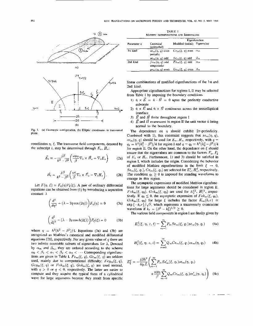
The problem is formulated with respect to elliptic-cylinder coordinates I . 77, z (Fig. l(b)); z is along the axis of the guiding structure, z = h cosh cos T I , y = h sinh [ sin rl and h is half the distance between foci F l , F2. The semi-elliptical interface between regions I and I1 is represented by the relations = (0, 0 5 r/ 5 ?r. The ellipticity is represented by the ratio e = b /a whereas the eccentricity is given by
The expressions to be developed for the guided waveforms will include the factor eJ(wt-P”); the phase constant /? will be determined through the analysis. The longitudinal field components are obtained by solving the second-order partial differential equation
(1)
where F stands for either E, or H,, IC = w(,LQ~) ‘ / * is the wavenumber and the operator 0; applies to the transverse
(1 - e 2 ) 1 / 2 .
(0: + ( I C 2 - P2))F(r / , 0 = 0
001 8-9480/94$04.00 0 1994 IEEE
892 IEEE TRANSACTIONS ON MICROWAVE THEORY AND TECHNIQUES, VOL. 42, NO. 5, MAY 1994
TABLE I MATHIEU EIGENFWNCTIONS AND EIGENVALUES
Eigenfunction Parameter q Canonical Modified (radial) Eigenvalue
(azimuthal) 1st kind ce,(v, q ) even Ce,([, q ) even a ,
periodic se,(v, q ) odd Se,([, q ) odd b”
2nd kind f e m ( v , 4) odd F e m ( F , 4 ) odd a m
nonperiodic ge,(v, q ) even Gem([, q ) even Pm
Jc-----2h I---.-------2a-+
(b) Fig. 1. plane.
(a) Geometric configuration, (b) Elliptic coordinates in transversal
coordinates 77, [. The transverse field components, denoted by the subscript t , may be determined through E,, H,:
linear combinations of modified eigenfunctions of the 1st and 2nd kind.
Appropriate eigenfunctions for regions I, I1 may be selected from Table I by imposing the boundary conditions
1) f i x = f i . 8 = 0 upon the perfectly conductive
2) f i x E and f i x I? continuous across the semielliptical
3) E, and 4) E and H evanescent in region I1 the unit vector f i being
The dependence on 77 should exhibit 27r-periodicity. Combined with l), this constraint suggests that sem(q, q ) , cem(v, q ) should be used for E,, H,, respectively, with q = q1 = h2(k? - p2)/4 for region I and q = qo = h2(ICi - p2)/4 for region 11. On the other hand, the dependence on < should ensure that the eigenvalues are common to the factors F,, Fs of E, or H,. Furthermore, 1) and 3) should be satisfied in region I, which includes the origin. Considering the behavior of modified Mathieu eigenfunctions in the limit [ -+ 0, Se,(<, ql) , Gem(<, 41) are selected for E:, H;, respectively. The condition q1 2 0 is imposed for standing waveforms to emerge in this region.
substr-te
i2terface- finite throughout region I
normal to the boundary.
The asymptotic expressions of modified Mathieu eigenfunc- tions for large arguments should be considered in region 11. Fek,([, qo) , Gek,([, 40) are used for EfI, Hi’, respec- tively. If qo 5 0, the asymptotic expression of Felcm(<, 40).
Let F(771 I) = Fq(rl)FE([). * Pair of ordinary equations can be obtained from (1) by introducing a separation constant X
Gekm([, qo) for large [ includes the factor Km(IC,r) a exp { -ICrr}/fi, which represents a transversely evanescent waveform if IC, = (p2 - ki)l/’ 2 0.
The various field components in region I are finally given by
(3a)
m=l where q = h2(IC2 - p2)/4. Equations (3a) and (3b) are recognized as Mathieu’ s canonical and modified differential
two infinite countable subsets of eigenvalues for X. Denoted
a0 < < a1 < p2 < a2 < .. . Corresponding eigenfunc- tions are given in Table I. Fern([, q ) , Gem(<, q ) are seldom used, mainly due to computational difficulty; Fegm(<, q ) ,
equations [21], respectively. For any given value of q there are 00
H i ( [ , 771 2, t ) = C Q m C e m ( [ r 41)cem(77, 41) (4b) by am and pm, they are ordered according to the scheme m=O
E: = ( g P , S e A ( [ , ql)sem(q, q l ) Gey,([, q ) or Fekm([, q) , Gekm([, q ) are used instead, with q > 0 or q < 0, respectively. The latter are easier to compute and they acquire the typical form of a cylindrical wave for large arguments because they result from specific
4qlL m=l 00
+% QmCem(l, ql)ceL(V, 41) p m=O
PERDIKOURIS et a/.: EM-WAVE PROPAGATION THROUGH SEMI-ELLIFTIC CYLINDRICAL DIELECTRIC WAVEGUIDE
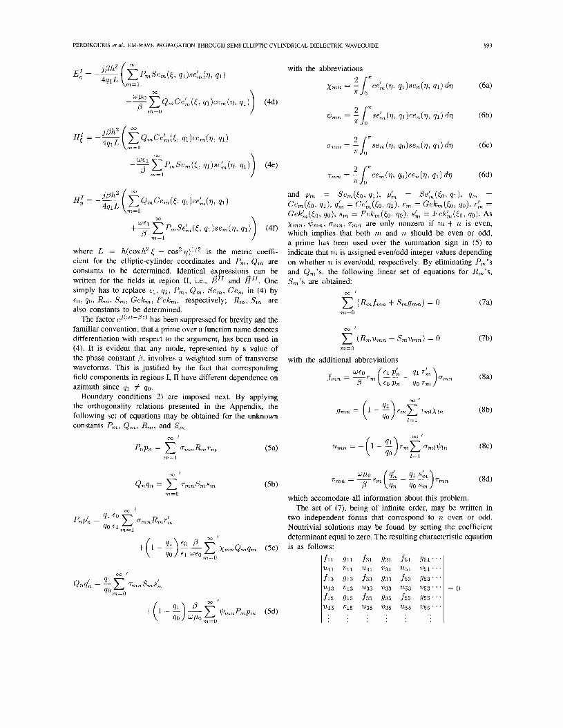
fll 911 f31 931 f5l 951" '
u11 u11 u 3 l u31 u51 u51 . ' . f13 g13 f33 933 f 5 3 9 5 3 " '
7113 2113 u33 u33 u 5 3 2153"'
f15 9 1 5 f 3 5 935 f 5 5 g 5 5 " '
2115 u15 7L35 u35 2155 u 5 5 " '
~
891
= 0
where L = h(cos h2 E - C O S ~ T / ) ~ / ~ is the metric coeffi- cient for the elliptic-cylinder coordinates and P,, Q, are constants to be determined. Identical expression: can be written for the fields in region 11, Le., E'' and HI'. One simply has to replace €1, q l l Pm, Q m , Se,, Gem in (4) by € 0 , 40, R m , S,, Gek,, Fek,, respectively; R,, S, are also constants to be determined.
The factor e j (w t -oz ) has been suppressed for brevity and the familiar convention, that a prime over a function name denotes differentiation with respect to the argument, has been used in (4). It is evident that any mode, represented by a value of the phase constant 0, involves a weighted sum of transverse waveforms. This is justified by the fact that corresponding field components in regions I, I1 have different dependence on azimuth since 41 # 40.
Boundary conditions 2) are imposed next. By applying the orthogonality relations presented in the Appendix, the following set of equations may be obtained for the unknown constants Pm, Q,, Rm, and S,
0 3 1
PnPn = CmnRmrm ( 5 4 m=1
m=O
Tmn = : lxcem(qi qO)"en(r/, 41) d q ( 6 4
and P m = Sem(Eo, ql ) , P A = sel ,( to, q i ) , qm = Cem(<ol qi) , qk = Cek(E0, qi ) , rm = Gekm(<o, qo) , ~k = Gekk(Eo, qo) , s, = Fekm(<o, qo) , s L = FekL(E0, 40). As xmn, $,,, gmn, r,, are only nonzero if m + n is even, which implies that both m and n should be even or odd, a prime has been used over the summation sign in (5) to indicate that m is assigned evedodd integer values depending on whether 71 is eventodd, respectively. By eliminating Pm's and Q,'s, the following linear set of equations for R,'s, S,'S are obtained:
0 3 1
( ~ m f m n + Smgmn) = 0 (7a) m=O
with the additional abbreviations
894 IEEE TRANSACTIONS ON MICROWAVE THEORY AND TECHNIQUES, VOL. 42, NO. 5, MAY 1994
TABLE I1 MODE CORRESPONDENCE
Semielliptical dielectric waveguide on substrate waveguide e H E m n ; m, n 2 1 e E H m n ; m, n 2 1
- TEon; n 2 1 Semielliptical dielectric waveguide on substrate e H E l n ; n L 1 .HEo,; 2 1 e T M n - l ; R 1 .EHmn; m, n 2 1
Circular cross section dielectric
HE,,; m, n 2 1 EH,,; m, n 2 1
tHEOn; n 2 1 TMon; n 2 1
Planar dielectric slab on substrate
eHE,,; m, n > 1 eTEn-l; n > 1
or
with n odd, or n even, respectively. The roots of (9) represent the phase constant p of guided modes. As H, is even with respect to 77, (4) represent even modes ,HE,, and .EH,,. Odd modes .HE,, and .EH,,, which would result by interchanging the expressions of (4a) and (4b) for E,, H , cannot be accommodated by this structure because 1) would not be satisfied by such waveforms. If the conductive substrate had been introduced at the x = 0 plane (Fig. l), ,HEm, and ,EH,, modes would have been excluded.
111. NUMERICAL RESULTS
A numerical investigation of modes in the semielliptical guiding structure which is supported by a perfectly conductive planar substrate is bound to refer to the circular cross section dielectric waveguide, thereby allowing for comparisons with published results. As interest is mainly in flat guiding struc- tures, this investigation may further refer to a planar dielectric slab on a perfectly conductive substrate. That marginal guiding structure is obtained in the limit a -+ 00, the slab thickness being equal to b. By using as criterion the asymptotic form of the characteristic equation near cutoff, it may be proven that modes of the semielliptical guiding structure correspond to modes of both reference guiding structures as shown in Table 11.
Calculations of P,, Q,, R,, S,, and /3 involve infinite- order determinants. Subdeterminants of order up to 17 x 17 have been used to calculate p’s with ten digit accuracy, whereas 12 x 12 is the greatest determinant previously reported [ 1 11. On the other hand, subdeterminants of order up to 32 x 32 were used for P,, Q,, R,, and S,, which have been extracted from (7) by singular value decomposition.
The first approximation to the phase constant p of guided modes is obtained by solving the reduced equation:
1;:: :;;I = o . (10)
Successive roots of ( IO) are represented by the subscript n in the notation e HE,, , e EH,,. Subsequent approximations to p’s result by padding the left-hand side of (10) with pairs of rows and columns from the determinants of (9), thus building higher-order subdeterminants until convergence is achieved. The number of rows and columns required for an accurate calculation of p’s increases with the aspect ratio a / b and, of course, with the frequency.
The truncation criterion for the infinite series expansion of field components is the continuity of tangential fields across the duct boundary. Unlike previous pertinent efforts, which have been limited to small eccentricities, the semielliptical guiding structure examined herein, involving large y values (up to 600), requires longer series in the expressions for the various field components and more difficulty in the determination of the roots of the characteristic equation [23]. On some occasions up to 50th-order Bessel functions have been used to calculate the modified Mathieu eigenfunctions.
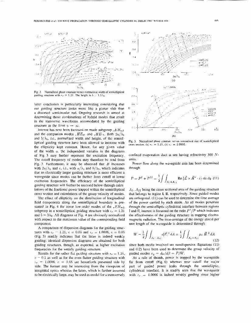
The first step has been to calculate the normalized phase constant B = (,L?/ko - 1)/(& - 1) against 2a/Xo, i.e., the normalized width of the semielliptical cross section; the height of the dielectric waveguide is kept constant at b = 1.5Xo. If a E [b , m), the ellipticity thus varying in the range [l, O), the diagrams of Fig. 2 with E , = 1.21 are obtained. The semielliptical cross section, which is semicircular at a = b, widens with 2a/Xo; as a result, more and more modes are accomodated within the waveguide. The distinction between ,EH,, and .HE,, modes is clear, especially far from cutoff. Each mode group is further seen to consist of mode subgroups eEH,l, .EHm2,... and e H E m l , .HE,2,..., respectively. It is noteworthy that modes .HE01 and .HE11, the latter being the fundamental mode, best fit among modes ,EH,1. Accordingly, modes eHEo2 and eHE12 fit among modes .EHm2 and so on. The horizontal lines in Fig. 2, marking the asymptotic B values of mode subgroups ,EH,1, ,HEm1, .EHm2,. . ’ , correspond to modes .TMo, eTEo, ,TMl, . . . of the dielectric slab obtained in the limit a + 03.
Naming the modes of the semi-elliptical guiding structure investigated through Fig. 2 is a task in itself. According to the established nomenclature [22], had as reference served the circular cross section dielectric waveguide with radius equal to a = b = 1.5X0, only modes .EH11, ,HEol, ?HE11,
and .HEl2 could have been recognized. The following technique has been used to name the remaining modes for any given value of 2a/Xo. The calculations are repeated with the guiding structure expanding in height so that b + a. The guiding structure finally obtained is again (semi- )circular and the modes of the initial semielliptical guiding structure are recognized by following the convergence of their B values to the known B values of modes in the corresponding circular cross section guiding structure.
Further calculations, not presented herein, point out that mode grouping is practically insensitive to t, and e. The
PERDIKOURIS ef a/ . : EM-WAVE PROPAGATION THROUGH SEMI-ELLIPTIC CYLINDRICAL DIELECTRIC WAVEGUIDE
~
89.5
2 a / &
Fig. 2. guiding structure with 6 , = 1.21. The height is b = 1.5X0.
Normalized phase constant versus normalized width of semielliptical
latter conclusion is particularly interesting considering that our guiding structure looks more like a planar slab than a distorted semicircular rod. Ongoing research is aimed at determining those combinations of hybrid modes that result in the transverse waveforms accomodated by the guiding structure in the limit a + oc.
Interest has next been focussed on mode subgroup .EHml and the companion modes ?HE01 and ?HEl1. Both 2a/& and b /&, Le., normalized width and height, of the semiel- liptical guiding structure have been allowed to increase with the ellipticity kept constant. Hence, for any given value of the width u, the independent variable in the diagrams of Fig. 3 may further represent the excitation frequency. The cutoff frequency of modes may therefore be read from Fig. 3. Furthermore, it may be observed that B increases with 2a/& and e, Le., with a/Xo and b / X o , which indicates that an electrically larger guiding structure is more efficient a waveguide since modes can be farther from cutoff at lower excitation frequencies. The efficiency of the semielliptical guiding structure will further be assessed below through calcu- lations of the fractional power trapped within the semielliptical cross section and calculations of the group velocity of modes.
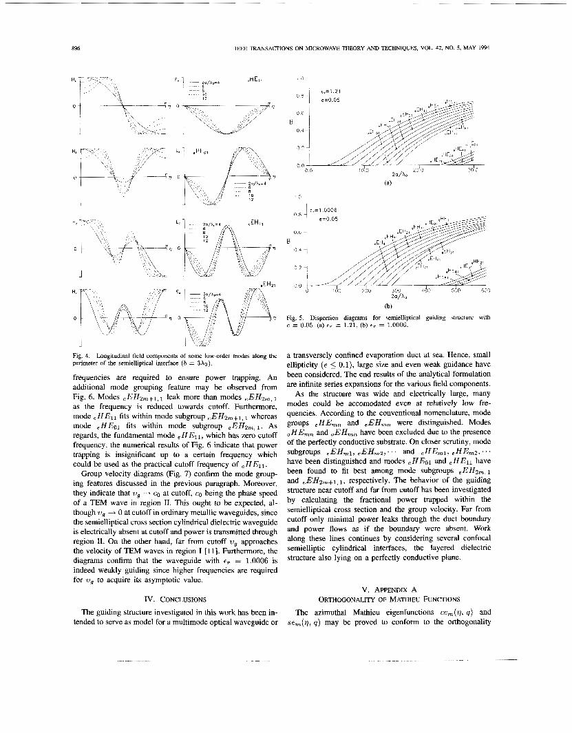
The effect of ellipticity on the distribution of longitudinal field components along the semielliptical boundary is pre- sented in Fig. 4 for some low-order modes of the .EHml subgroup in a semielliptical guiding structure with E , = 1.21 and b = 3x0. All diagrams of Fig. 4 are obviously normalized with respect to the maximum value of the corresponding field component.
A comparison of dispersion diagrams for the guiding struc- tures with E , = 1.21, e = 0.05 and t, = 1.0006, e = 0.05 (Fig. 5 ) readily indicates that the latter is indeed weakly guiding; identical dispersion diagrams are obtained for both guiding structures, though, as expected, at higher excitation frequencies for the weakly guiding structure.
Results for the rather flat guiding structure with t, = 1.21, e = 0.1 as well as for the even flatter guiding structure with t, = 1.0006, e = 0.05 are henceforth presented side by side. The former may be interesting from the viewpoint of integrated optics whereas the latter, which is further assumed to be electrically large, may be used as model for a transversely
(b)
Fig. 3. cross section. (a) cT = 1.21, (b) e,. = 1.0006.
Normalized phase constant versus normalized size of semielliptical
confined evaporation duct at sea having refractivity 300 N - units.
Power flow along the waveguide axis has been determined through
A I , A I I being the cross sectional area of the guiding structure that belongs to region I, 11, respectively. Since guided modes are orthogonal, (1 1) can be used to determine the time average of the power carried by each mode. As all modes penetrate through the semi-elliptic cylindrical interface between regions I and 11, interest is focussed on the ratio P'IP which indicates the effectiveness of the guiding structure in trapping electro- magnetic radiation. The time-average of the energy stored per unit length of the waveguide is determined through
since both media involved are nondispersive. Equations (1 1) and (12) have been used to determine the group velocity of guided modes vg = dw/@ = P/W.
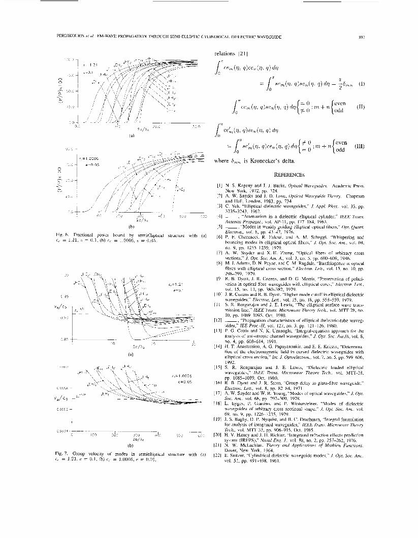
As a rule of thumb, power is trapped by the waveguide far from cutoff (Fig. 6) whereas near cutoff the major part of guided power leaks through the semielliptic, cylindrical interface. It is readily seen that the waveguide with t, = 1.0006 is indeed weakly guiding since higher
896 IEEE TRANSACTIONS ON MICROWAVE THEORY AND TECHNIQUES, VOL. 42, NO. 5, MAY 1994
1
Fig. 4. Longitudinal field components of some low-order modes along the perimeter of the semielliptical interface ( b = 3x0).
frequencies are required to ensure power trapping. An additional mode grouping feature may be observed from Fig. 6 . Modes eEH2m+1,1 leak more than modes eEH2m, 1
as the frequency is reduced towards cutoff. Furthermore, mode eHEl l fits within mode subgroup eEH2m+l, 1 whereas mode ,HE01 fits within mode subgroup eEH2,,1. As regards, the fundamental mode eHE1l, which has zero cutoff frequency, the numerical results of Fig. 6 indicate that power trapping is insignificant up to a certain frequency which could be used as the practical cutoff frequency of eHE1l.
Group velocity diagrams (Fig. 7) confirm the mode group- ing features discussed in the previous paragraph. Moreover, they indicate that wg -+ co at cutoff, co being the phase speed of a E M wave in region 11. This ought to be expected, al- though wg -+ 0 at cutoff in ordinary metallic waveguides, since the semielliptical cross section cylindrical dielectric waveguide is electrically absent at cutoff and power is transmitted through region 11. On the other hand, far from cutoff wg approaches the velocity of TEM waves in region I [ 111. Furthermore, the diagrams confirm that the waveguide with t, = 1.0006 is indeed weakly guiding since higher frequencies are required for wg to acquire its asymptotic value.
IV. CONCLUSIONS
The guiding structure investigated in this work has been in- tended to serve as model for a multimode optical waveguide or
' "1 0 8
0 6
B 0 4
0 2
00
E , = 1.0006 I _ _ n n c
I d 0 260 360 4d0 560 6d0 2 a / h
(b)
Fig. 5. Dispersion diagrams for semielliptical guiding structure with e = 0.05. (a) eT = 1.21, (b) cT = 1.0006.
a transversely confined evaporation duct at sea. Hence, small ellipticity (e 5 O.l), large size and even weak guidance have been considered. The end results of the analytical formulation are infinite series expansions for the various field components.
As the structure was wide and electrically large, many modes could be accomodated even at relatively low fre- quencies. According to the conventional nomenclature, mode groups e HE,, and eEHmn were distinguished. Modes .HE,, and .EHm, have been excluded due to the presence of the perfectly conductive substrate. On closer scrutiny, mode
have been distinguished and modes eHEo1 and eHEl l have been found to fit best among mode subgroups ,EH2,, 1
and eEH2,+1,1, respectively. The behavior of the guiding structure near cutoff and far from cutoff has been investigated by calculating the fractional power trapped within the semielliptical cross section and the group velocity. Far from cutoff only minimal power leaks through the duct boundary and power flows as if the boundary were absent. Work along these lines continues by considering several confocal semielliptic cylindrical interfaces, the layered dielectric structure also lying on a perfectly conductive plane.
subgroups eEHm1, eEHm2,-. . and eHEm1, eHEm2,...
V. APPENDIX A ORTHOGONALITY OF MATHIEU FUNCTIONS
The azimuthal Mathieu eigenfunctions ce,(q, q ) and sem(q, q ) may be proved to conform to the orthogonality
PERDIKOURIS et a/ . : EM-WAVE PROPAGATION THROUGH SEMI-ELLIPTIC CYLINDRICAL DIELECTRIC WAVEGUIDE 897
0 0
X - n ? a -\ a v
2‘
1 &,=1.0006 e:F> e
eE-. e=O 05 \-,-
2 a / b
(bj
Fig. 6. Fractional power bound by semielliptical c , = 1.21, e = 0.1, (bj FT = 1.0006, e = 0.05.
100
structure with (a)
10000 1
1 0 9995
VJ.0
0 9995
where S,, is Kronecker’s delta.
REFERENCES
181
I91 &,=1.21
e=0.1
0 85
(bj
Fig. 7. Group velocity of modes in semielliptical structure with (a) f, = 1.21, c = 0.1, (b) 6,- = 1.0006, P = 0.05.
N. S. Kapany and J. J. Burke, Oprical Waveguides. Academic Press, New York, 1972, pp. 328. A. W. Snyder and J. D. Love, Optical Waveguide Theory. Chapman and Hall, London, 1983, pp. 734. C. Yeh, “Elliptical dielectric waveguides,” J. Appl. Phys., vol. 33, pp. 3235-3243, i962. -, “Attenuation in a dielectric elliptical cylinder,” IEEE Trans. Antenna Propagar., vol. AP-11, pp. 177-184, 1963. -, “Modes in weakly guiding elliptical optical fibers,” Opt. Quant. Electron., vol. 8 , pp. 43-47, 1976. P. F. Checcacci, R. Falciai, and A. M. Scheggi, “Whispering and bouncing modes in elliptical optical fibers,” J . Opt. Soc. Am., vol. 69, no. 9, pp. 1255-1259, 1979. A. W. Snyder and X.-H. Zheng, “Optical fibers of arbitrary cross sections,” J. Opt. Soc. Am. A., vol. 3, no. 5 , pp. 60g609, 1986. M. J. Adams, D. N. Payne, and C. M. Ragdale, “Birefringence in optical fibres with elliutical cross section,” Electron. Left., vol. 15, no. 10, pp. 298-299, 1979’. R. B. Dvott. J. R. Cozens, and D. G. Morris, “Preservation of polar- , . sation in optical fibre waveguides with elliptical cores,” Elecrron. Lett., vol. 1.5, no. 13, pp. 380-382, 1979. J . R. Cozens and R. B. Dyott, “Higher-mode cutoff in elliptical dielectric waveguides,” Electron. Left., vol. 15, no. 18, pp. 558-559, 1979. S. R. Rengarajan and J. E. Lewis, “The elliptical surface wave trans- mission line.” IEEE Trans. Microwave Theory Tech., vol. M’Il-28, no. i ~~
~~ ~~~~~
I O , pp. 1089-1095, Oct. 1980. -, “Propagation characteristics of elliptical dielectric-tube waveg- uides,” IEE Proc.-H, vol. 127, no. 3, pp. 121-126, 1980. P. G. Cottis and N. K. Uzunoglu, “Integral-equation approach for the analysis of anisotropic channel waveguides,” J. Opr. Soc. Am./A, vol. 8 , no. 4, pp. 608-614, 1991. H. T. Anastassiou, A. G. Papayannakis, and E. E. Kriezis, “Determina- tion of the electromagnetic field in curved dielectric waveguides with elliptical cross section,” Int. J. Optoelecrrun., vol. 7, no. 5 , pp. S99-606, 1992. S. R. Rengarajan and J. E. Lewis, “Dielectric loaded elliptical waveguides,” IEEE Trans. Microwave Theor)? Tech., vol. M T - 2 8 , pp. 1085-1089, Oct. 1980. R. B. Dyott and J. R. Stem, “Group delay in glass-fibre waveguide,” Electron. Lett., vol. 8, pp. 82-84, 1971, A. W. Snyder and W. R. Young, “Modes of optical waveguides,” J . Opt. Soc. Am., vol. 68, pp, 297-309, 1978. L. Eyges, P. Gianino, and P. Wintersteiner, “Modes of dielectric waveguides of arbitrary cross sectional shape,” J. Opr. Soc. Am., vol. 69, no. 9, pp. 1226-1235, 1979. J. S. Bagby, D. P. Nyquist, and B. C. Drachman, “Integral formulation for analysis of integrated waveguides,” IEEE Trans. Microwave Theory Tech., vol. M n - 3 3 , pp. 906915 , Oct. 1985. H. V. Hitney and J. H. Richter, “Integrated refraction effects prediction system (IREPS),” Naval Eng. J., vol. 88, no. 2, pp. 257-262, 1976. N. W. McLachlan, Theory and Applications of Mathieu Functions. Dover, New York, 1964. E. Snitzer, “Cylindrical dielectric waveguide modes,” J . Opr. Soc. Am., vol. SI, pp. 491-498, 1961.
898 IEEE TRANSACTIONS ON MICROWAVE THEORY AND TECHNIQUES, VOL. 42, NO. 5 , MAY 1994
[23] D. Clemm, “Characteristic values and associated solutions of Mathieu’s differential equation,” Commun. ACM, vol. 12, no. 7, pp. 399407, 1969.
E. E. Kriezis (M’71-SM’82) received a degree in mathematics from the University of Thessaloniki, Greece. He then received a diploma in electrical engineering and a doctor’s degree from the National Technical University of Athens, Greece.
Since 1974, he has been a Professor in the Department of Electrical Engi- neering at the University of Thessalonilu, where he teaches electromagnetic field theory. His research encompasses problems of the field related to eddy currents and to the problems of scattering related to remote sensing. He has served as chairman of the Electrical Engineering Department for five years.
Dr. Kriezis is the author of the books Eddy Currents in Linear Conducting Media (Elsevier, 1985) and Electromugnetics and Optics (World Scientific, 1992). He has been the recipient of the Embirikion Award for Science and Technology and he is a member of the Technical Chamber of Greece and Eta Kappa Nu.
A. c. Perdikouns received the Dipl.Eng. degree in 1986 and the Dr.Eng. degree in 1992 from the Electrical Engineering Department, Faculty of Technology, Aristotle University of Thessaloniki, Greece.
He is currentb’ with the Greek Navy. He is a member of the Technical Chamber of Greece.
D. P. Chrissoulidis (S’80-M’84) was born in Thes- saloniki, Greece, in 1956. He received the DipLEng. degree in 1979 and the Dr.Eng. degree in 1984 from the Electrical Engineering Department, Faculty of Technology, Anstotle University of Thessaloniki, Greece. He has spent the year 1988-1989 work- ing as post-doctoral fellow by the Environmental Surveillance Technology Programme, Royal Norwe- gian Council for Scientific and Industrial Research, Kjeller, Norway.
He is currently an Assistant Professor with the Electncal Engineenng Department, Faculty of Technology, Aristotle Yni- versity of Thessalonilu, Greece. His research interests include the are& of electromagnetic wave propagation, remote sensing of the environment and underwater acoustics. He authored several papers and coauthored the book Electromagnetics and Optics (World Scientific, 1992). Dr. Chrissoulidis is a member of IEEE, AGU, URSI (Commission F), and of the Technical Chamber of Greece.


![Elliptic genera and elliptic cohomology - Long Island Universitymyweb.liu.edu/~dredden/EllipticGenera.pdf · the history of elliptic genera and elliptic cohomology, [Seg] explains](https://img.pdfslide.net/doc/110x75/5edc8698ad6a402d66673899/elliptic-genera-and-elliptic-cohomology-long-island-dreddenellipticgenerapdf.jpg)