Embed Size (px)
Citation preview

EM303Caravan ManoeuvringSystem

TABLE OF CONTENTSPackage contents (parts list)IntroductionIntended useSpecificationsInstallation - safety guidelinesInstallation - mechanical componentsInstallation - electrical/electronic componentsInstallation - twin axleOperation - safety guidelinesOperation - motor unitsOperation - remote control handsetOperation - electronic control unitOperation - getting startedOperation - hitching and unhitchingMaintenanceTrouble-shooting
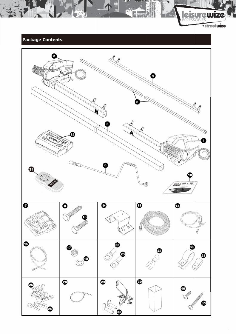
PACKAGE CONTENTS
Ref Qte Description
1 1 Motor unit (A)2 1 Motor unit (B)3 1 Main cross bar4 1 Cross actuation centre bar5 2 Cross actuation insert bars6 1 Engagement tool7 2 Aluminium chassis clamp plates (set)8 4 Bolt - M10x609 2 Chassis U plate10 1 Instruction manual11 1 Convoluted cable trunking12 1 Positive (+) red battery cable 1.8m including fuse
Holder and 80A fuse13 1 Negative (-) black battery cable 1.6m14 8 Bolt - M10x5015 12 Nylon nut M1016 24 Washer 10mmØ17 20 Screw - M4x1518 10 Cable trunking P-clips 19.2mm19 10 Cable P-clips 10.4mm20 4 Battery terminal connector 8mmØ21 2 Battery terminal connector 6mmØ22 4 Spade fork connector23 3 Cable number markers (1,2,3,4)24 3 Cable polarity markers (+,-)25 10 Cable ties 2x7026 1 Battery isolation switch, cover & key27 2 Roller distance spacers 20x2028 1 Remote control handset with lanyard29 1 Electronic control unit30 2 Rubber isolation shell for battery isolation switch31 2 Screw – M5x40
INTRODUCTION
Congratulations on choosing the emove EM303 caravan manoeuvring system. This has been producedaccording to very high standards and has undergone careful quality control procedures.
Simply by using the remote control handset you can move your caravan effortlessly into any position requiredwithin operating guidelines. Soft start and soft stop technology allows you to manoeuvre your caravan evenmore accurately without any shocks.
The caravan manoeuvring system consists of two 12V motor-power rollers, a 12V electronic control unit and aremote control handset. To function, the motor-powered rollers must be engaged against the tyres of yourcaravan. The supplied cross actuation device enables you to engage both rollers at the same time from one sideof your caravan. Once this is done the manoeuvring system is ready for operation. The remote control will allowyou to move your caravan in any direction. You can even rotate the caravan on its own axis, without movingforwards or backwards (this functionjust can workunderthe “single-axle function”).
Before proceeding with installation and starting to use the manoeuvring system, please readthis manual very carefully and be aware of all the safety instructions! The owner of thecaravan will always be responsible for correct use. Keep this manual inside your caravan forfuture reference.
INTENDED USE
The emove EM303 caravan manoeuvring system is suitable for single axle and double axle caravans.
Suitable only for L-profiled and U-profiled chassis with a chassis thickness between min. 2.8mm and max.3.5mm.
Depending on the weight of the caravan, the manoeuvring system cannot overcome obstructions that are morethan about 2cm in height without assistance (please use wedges as a ramp).
The standard installation kit only provides parts for installing the caravan manoeuvring system within themeasurements given in Fig. 14.
SPECIFICATIONS
Designation emove EM303Operational voltage 12 Volt DCAverage current consumption 20 AmpereMaximum current consumption 100 AmpereTransmitting frequency remote control 868MHzSpeed approx. 9cm per sec.Weight (2 motor set) approx. 37kg (exclusive battery)
Minimum width (caravan/trailer) 1800mmMaximum width (caravan/trailer) 2500mmMaximum tyre width 205mmPower source (battery) LiFePO4: 12V, 20Ah
Lead acid: 12V, 80Ah (min.)
INSTALLATION - SAFETY GUIDELINES
Read this user manual carefully before installation and use. Failure to comply withthese rules could result in serious injury or damage to property.
These symbols identify important safety precautions. They mean CAUTION! WARNING!SAFETY FIRST! IMPORTANT INFORMATION!
Before starting installation under the caravan:
Check the towing load of your vehicle and the gross weight of your caravan in order to establish whether theyare designed for the additional weight. The manoeuvring system itself has a weight of about 37kg and atraditional lead acid battery has a weight of about 20-25kg .
Check the minimal installation dimensions of the manoeuvring system based on figure 14.
Permissible overall Weight single axle (2 motors) 2250kg hard flat surfaces, 1800kg other surfaces,1500kg on 18% gradient.
Permissible overall Weight double axle (2 motors) 2250kg hard flat surfaces, 1800kg other surfaces,1500kg on 18% gradient.
Permissible overall Weight double axle (4 motors) 3500kg hard flat surfaces, 2500kg other surfaces,1800kg on 18% gradient.

Check that the caravan is disconnected from the battery supply and the mains electrical supply.
Only use adapters and accessories that are supplied or recommended by the manufacturer.
Check that the tyres are not over worn and do have the same size and design (fitting to new or nearly newtyres is the best option).
Make sure that the tyre-pressures are correct to the manufacturer’s recommendation.
Make sure the chassis is in good condition without any damage and is free from rust, dirt etc.
Stop work immediately if you are in doubt about the assembly or any procedures and consult one of ourengineers (Please refer to contact information on the last page of this manual).
Locate the battery isolation switch to be accessible at all times when parking and moving the caravan.
Do not remove , change or alter any parts of the chassis, axle, suspension or brake mechanism. Any drilling ofholes in the chassis is not allowed.
Do not install the unit if you are under the influence of drugs, alcohol or medication that could impair yourability to use the equipment safely.
INSTALLATION- MECHANICAL COMPONENTS
FOR PROFESSIONAL INSTALLATION ONLY! These instructions are for general guidance.
Installation procedures may vary depending on caravan type.
Working under a vehicle without appropriate support is extremely dangerous!
Please refer to Fig. 13 for an overview of the whole assembly fully fitted.
Place the caravan on a hard, level surface. The use of a lifting ramp or an assembly pit is ideal for access andpersonal safety.
Unpack all the components and check for the presence of all parts (see package contents list). Write down, onthe product warranty registration card, the 10-digit serial number (this is located on an aluminium plate on theside of one of the motor units).
Clean the area of your chassis where you need to mount all components to ensure a good fitting.
Make sure the caravan is prepared for installation. Check before installation that important areas, such asdrains/spare tyre etc. do not cause any obstruction to the function of the caravan manoeuvring system.
Ensure both rollers are in the DISENGAGED position (Fig. 10A), as the unit will not fit correctly otherwise (Note:when fully disengaged, the pointer is positioned in the beginning of the yellow area).
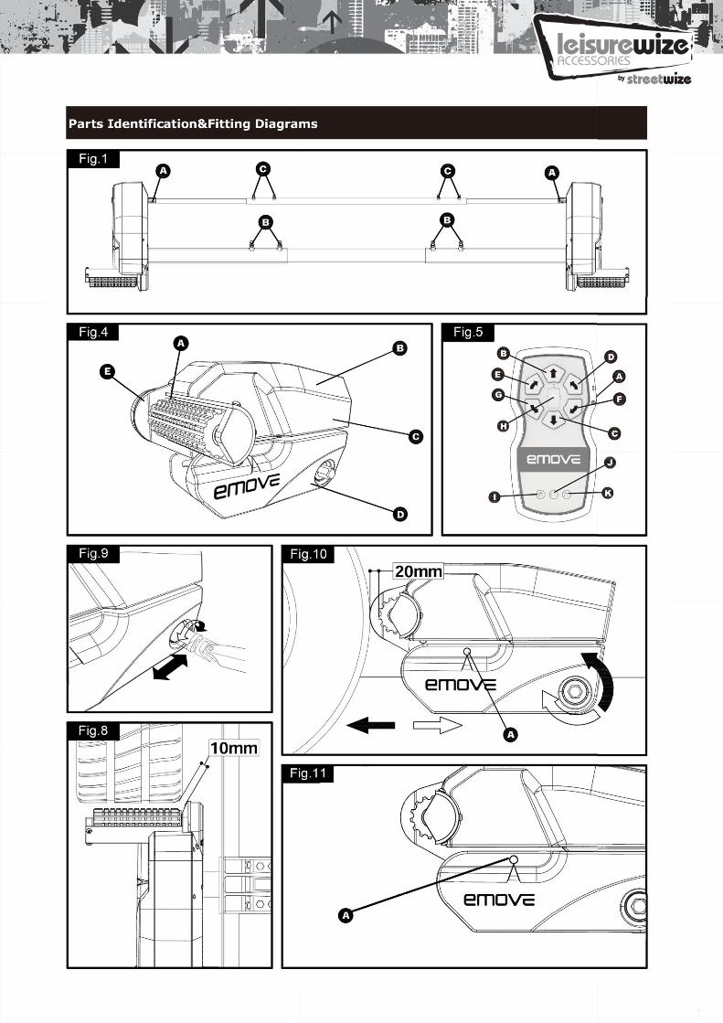
Loosely assemble the left hand motor unit (1), right hand motor unit (2) and main cross bar (3) (Fig. 1). Thenuts (Fig. 1B), on the cross bar (3) to secure both motor units, must be no more than finger-tight at this stage.
Note : In principle, the unit should be fitted in front of the caravan road wheels, but if fitting in this position isnot possible because of obstacles or a too high hitch ball weight, it is permissible to fit it to the rear of thewheels by rotating the whole assembly (Fig. 1) by 180° degrees.
Loosely fit the two clamping assemblies (7) to the chassis (Fig. 2 & 13) and attach. Use the bolts M10x60, nutsM10 and washers M10 (8,17,18) and put them in the diagonal positioned holes of the aluminium chassis clampplates. Nuts must be no more than finger-tight.
Assemble the pre-mounted manoeuvring system on the aluminium chassis clamp plates by using the two U-shaped brackets (9), bolts M10x50, nuts M10 and washers M10 (16,17,18). Nuts must be no more than finger-tight.
Make sure that aluminium drive rollers of the motors are approximately on the same altitude as the centre(axle) of the caravan wheel (± 20mm). To compensate a possible unevenness (and lower the motors),emove has a set of distance plates available. One set can compensate 15mm. In total three sets can be usedso that an altitude of 45mm can be compensated.
Adequate ground clearance: Please notice that the min. distance between the lowest line of
motors and ground is 110mm, no matter what kinds chassis or install situation.

Assemble the parts of the cross actuation bar (4 & 5) and connect them to the motor units (1 & 2) with the nylon nut and bolt (factory fitted) onto the cross actuation bar-connectors (Fig. 1 & Fig. 1A). Nuts must be no more than finger-tight at this stage.
Make sure that the main cross bar (3) and the cross actuation centre bar (4) are positioned in the middle of the caravan (the centre of the bar is marked).
With the main assembly is loosely fitted onto the chassis, slide the whole assembly along the chassis until the rollers are 20mm away from the surface of the centre each tyre (Fig. 10). Two 20mm spacers (30) are provided.
It is vitally important that each roller is at exactly the same distance away from the tyre. The whole assembly must be parallel to the caravan/trailer axle.
Slide the motor units in or out of the cross bar (3) accordingly to ensure the roller will have the maximum possible contact with the tread of the tyre. Ensure that the position of each motor unit does not obstruct shock absorbers (if fitted) and that the gear cover (Fig. 8) is not too close to the surface of the tyre/shock absorber. The minimum clearance when the drive units swivelled in is 10mm.
Fully tighten the four bolts (Fig. 1B) on the main cross bar (3) and the four bolts (Fig. 1C) on cross actuation assembly (4 & 5).
Fully tighten all the nylon nuts on both clamping assemblies (Fig. 2). First tighten the diagonal placed M10x60 bolts with a 20Nm torque, and then M10x50 bolts to a 40Nm torque.
Re-check the distance of 20mm from the rollers to the tires, the position of the aluminium rollers in addition to the surface of the tire and finally the distance between the plastic gear cover (Fig. 8) and the tires & shock absorbers (>10mm). The weight of the caravan musty be on the wheels when doing this. If necessary, loosen the bolts and re-adjust the position of the assembly.
Re - check that all bolts/nuts have been tightened to the correct torque!
The main mechanical components have now been installed. INSTALLATION - ELECTRICAL
Make sure the 12V supply from the battery and any 230V electricity supply are disconnected.
Remove battery cable terminals and disconnect any external electrical power before starting work.
Find a suitable place for the electronic control unit (32), such as a storage area, under a seat or a bed. Make sure this place is dry and close to the battery (40cm to 60cm). The electronic control unit can be mounted vertically on a side wall or be mounted flat. When mounted vertically, the connections must point downwards to avoid any short-circuits by objects falling into.
Fix the electronic control unit securely into position with two screws M5x40 (35). Note: if the provided screws are not of suitable length or type for the desired location/material please substitute these as appropriate.
Drill a 25mm hole through the floor of the caravan approximately 150mm centrally in front of the control unit (32) terminals.
Caution! Take extra care to avoid any chassis members, gas pipes and electrical wires!
Route and connect the motor-cables in accordance with wiring diagram (Fig. 12) (red = positive, black = negative).
The wiring diagram (Fig. 12 + Table. A (see below)) depicts the wiring route when installing the motor units in front of the wheels/axle towards the ‘A’ frame. Please refer to table B (below) for fitment of the motor units to the rear of the axle. Table . A FRONT OF AXLE FITTING Motor A Positive (+) cable to terminal 4 Motor A Negative (-) cable to terminal 3 Motor B Positive (+) cable to terminal 2 Motor B Negative (-) cable to terminal 1
Table . B REAR OF AXLE FITTING Motor A Positive (+) cable to terminal 1 Motor A Negative (-) cable to terminal 2 Motor B Positive (+) cable to terminal 3 Motor B Negative (-) cable to terminal 4
Mark the motor cables for both motor units using the cable markers (23). The cables for the left and the right
motor should have the same length. Avoid any loops.

Connect the spade connectors to the motors. Please note that the red cable is connected to the terminal underthe moulded ‘+’ symbol on the weatherproof terminal cover.
Remember to leave a small amount of slack cable near the motors to allow for their movement when the driverollers are engaged.
Route the motor cables along the underside of the caravan floor, inside the supplied convoluted trunking (11)(this will protect the electrical cables against sharp edges and dirt) and through the drilled hole.
Secure the cable trunking (11) to the chassis or under body of the caravan by using the P-Clips (20) and screws(19).
Once the motor cables are through the drilled hole next to the control unit (32), cut the cables, ensuring thatthey are same length. Remove approx. 5mm of the insulation from the ends. Fix the spade fork connectors (24)to the motor cables by using crimping pliers. A secure and good quality connection on each cable is essential.
Attach the spade fork connectors to the terminals on the control unit (see wiring diagram Fig. 12) and fix themtightly by the screws. A safe and good quality connection on each cable is again essential.
Find a suitable place for the battery power isolation switch (29) which includes an external holder with hingedcover. Important: The switch must be mounted onto the exterior body of the caravan and be easily
accessible from the outside of the caravan in case of any emergency. The switch must be mounted closeto the location of the battery in order to keep the length of the battery cables to a minimum.
Use the cardboard template to position the hole positions and the drill holes. Mount the switch and the housingwith the bolts, washers and nuts, and finally mount it on the caravan with stainless steel screws (19).
Route the positive (+) power cable (including fuse) from the battery to the battery power isolation switch (29)and than further to the control unit (32).
The electronic connections of the battery power isolation switch (29) must be covered by the supplied rubberisolation shells (33).
Route the negative (-) power cable directly to the control unit (32).
No cables may be routed over the control unit!
Again it is recommended to use the supplied trunking (11) to protect the cables against sharp edges. Attach thetrunking with P-clips (20) and P-clip screws (19).
Cut the cables to an appropriate length and remove approx. 5mm of the insulation from the ends. Fix the spadeconnectors by using crimping pliers. Two types of battery terminal connector (22 & 23) are provided for use asappropriate. A secure and good quality connection on each cable is essential.
Connect the battery cables (14 & 15) to the control unit (32): Attach the spade fork connectors to the positive(+) en negative (-) terminal of the control box and fix them tightly by the screws.
Connect the battery cables to the existing battery terminals (red = positive, black = negative).
Caution! Make sure that you do not reverse the Positive (+) and Negative ( - ) connections.
Incorrect connection (reverse polarity) will result in damage to the control unit.
Seal the 25mm hole in vehicle under body using plastic body sealant.
Installation of the caravan manoeuvring system is now complete.
INSTALLATION– TWINAXLE
This manual describes the general installation and use of the manoeuvring system for single axle caravans.When you use the manoeuvring system for a twin axle caravan, please check the following:
Permissible overall weight twin axle (2 motors) 1800kg (1500kg on 18% gradient)Permissible overall weight twin axle (4 motors) 2500kg (1800kg on 18% gradient)
:srotom2
irdlilwsleehwlla,sevrucgnikamnehwnoitcunfelxaniwtehtnI.navaracsginrvueonamethtahtos,)T3.giF(noitisopelxaniwtehtottunilortnoc
elxaniwt/elgnisethevomdnahctiwsnoitalosirewopyrettabehtffffonruTTuwtrofderaperpebtsumylno)4(tunilortnoccinortceleehT.navaracelxaxaniwtanometsysgnirvueonamsrotom2agnlliatsinroferudecorpehT
:srotom4
norfnidetunomtseginrvueonamstnenopmoccinortcele/lcairtceleehtgnillatsniroferudecorpethwolloF
mtesgnirvueonamethrofemitenodnaelxaniwtehtfotnorfnidetnuomno:eciwtstnenopmoclcainahcmeehtgnillatsniroferudecorpethwolloF
.metsysginrvueonamfostesowthtiwnehttubnavaracelxaxaniwtanometsysgnirvueonamsrotom4agnlliatsinroferudecorpehT
.elxaniwtmehtrofemitenodnaelxaniwtehtfot
reffffidatatubevelxaniwtarofdesuebnacmetsys
ethno)T/S3giF(hctiwsnoitcnuf:esuelxaniw
elgnisarofsaemasethsinavaracelx
.deepstne
ehtrofemiteno:eciwt
.elxaniwtehtdnhiebdetunomtseginrvueonamehtrofemiten
elgnisarofnahtrailmissinavaracelx
htobylppusotyrettabyticapacreh
ethdnhiebdetnuomtseginrvueonam
elxaniwtarofdesuebnacmetsysethno)T/TS3giF(hctiwsnoitcnuf
.navaracelxaniwtan.)sehctiwsnoitalosirewopyrettabfoo
:erudecorpginwollofehtgnisusehT.)32(tsednahetomerenoynl
.deepstnereffffidatatubev
atahtdnayrettabehtfonoitidnocerasrellorevirdehttahterusnedna
ethnoDELneergehT.)A5.giF(I-”
)D3&C3,B3.giF(tunilortnocethn
.etelpmocsinoitasinorhcnysethtah3tuobaroftsednahlortnocetom
lortnocetomerethnodna)B3.giF
nehW:etoN
aracttunilortnocbehtffffonruTTuelehtobwoN
wtesutonoDonamfostse
sdnahetomerehtobyllainF
tnI.nav
thkcehC
gihenoesuotyrasseceneblilwtisrotomruofehtgnlliatsin
sginrvueonamethtahtos,)T3.giF(noitisopelxaniwtehtoelxaniwt/elgnisethevomdnahctiwsnoitalosirewopyrettab
:esuelxaniwtrofderaperpebtsum)4(stniulortnoccinortce
nometsysgnirvueonamsrotom4arofseirettabetarapseowwtdnastunilortnoccniortecleowtgnidlucni(metsysgnirvue
stunilortnoccniortcelehtobhtiwdesinorhcnysebotdeentesofoesuehtrofderaperpebtsum)4(stunilortnoccniortcele
irdlilwsleehwlla,sevrucgnikamnehwnoitcunfelxaniwteh
.tunilortnocehttatneserpsiV12foethkcehc,detecnnocylreporpsiyrettabehttahtkcehC.dei
asnoitcurtsninoitallatsniethhtiwecnadroccaninoitallatsineh
.noerasehctiwsnoitalosiyrettabhtobtahterusn
.ylwolshsalfotstrats)H5.giF(tesdnahlortnocnO“othctiwsedlisehtgnidilsybtesdnahlortnocetomereht
.ylwolshos’’sDELeerhtllA.tniulortnocehtno)A3.giF(nottubtesere
tmrifnocotpeebtrohsaeviglilwrezzubtesdnahethnehTmerethnonottub)C5.giF(esreverdna)B5.giF(sdrawrofht
.ylsuouintnocetainmillulilw)H5.giF(F(tunilortnocethnoDLEneergeht,noitasniorhcnyslufssecc
.tiunlortnoccinortcelednocesehthtiwerudecorpsih
oegatlovlippaton
thkcehC
neesaelP
cetomeretavitcA
hsalflilwethsserP
.sdnocesobsserP
tsednahcusretfftA
ttaepeR
railimaf oyesirailimafarepoecitcarP
OITAATREPO
su,noitarepooitallatsinehT
ethnruTTu
hW
ofeB
metsysginrvueonam/tesdnahehthtiwflesruofgnisuerofebaeraneponanimetsysginrvueonamehtgnita
SENILEDIUGYTEFAS-NN-O
sehtotreferesaelp,snoitcunfnottubdnaDELethlladnaensiesuelxaniwtrofmetsysginrvueonamnavaracehtfono
ulortnochtobosniaga”nO“nehtdna”ffffO“tsednahetomer
orrognivomybdeppartemocebnacydobehtnodeirracstceehtorosregnif,sriahontahterusne,metsysethgnitarepone
awehtfotuollewtpekerastepdnanerdlhictahterusnesya
.dettifneebsahmetsysgnirvueonamethnemitllata,erawaebesaelpnavaracehtginovmrogniwotne
narofmetsysgnirvueonamnavaracehtkcehcsyawla,esuero
.noitarepo
.sertem5deecxetonseodnavaracethdnalortnocetoonamginrud,tahterusekamsyawla,htgnertslangisniatinam
.hcyletaidemmiekarbdnahethnolulp,snoitcnuflamfotneveeh
ylulfotsisihT.emittsrifethrof
.lanuamsihtfosretpahcdradnatehtfosliatedroF.etelpmocwo
.detavitcaeblilwstuni
.e(strapgnitatorehtoynarognhitolc,strapydobre
.noitarepognirudy
decudersiecnaraelcdnuorgtaht,s
.egamadyn
metsysginrvueonamehtecneh,secudeebyamerehtoS.stcejboroniarretlanr
ehtneewtebecnatsideth,ginrvueo
rewopnoitalosinimaehtffffonrutdna
.)srellorevird.gejboehW
awlA
ehwehW
omermoTTo
ctiwshtnI
otsyamhwnavaracehtdnuorasaerallams
angisoidarafoerutanethoteuD
odnavaracethdnalortnocetomer
.yliratnemompernoitpecerfoytilauqetherehretxeybdetpurroctegnacti,l
.sertem5deecxetonse

dlk2500ddtikrowefaslatotehtdeecxetonoD
navaracethfodaolyapehtsecudervueonamehttahterawaebsyawlA
.metsysehtrofdnaserysimetsysgnirvueonamehtnehwserytethmorfdegagnesidylulfera
.desuera)elxaniwt(srotom4nehw)daolgnidulcninavarac(thgiewn2nehw)daolgindulcninavarac(thgiewnedalgk1800fodaolgn
.nshitoS.reilartronavaracruoyfothgiewehtsesaercnimetsysgnirv
ethybdegrahcsideblilwyrettabeth,ff,fffohctiws’tnoduoyfI.)elpfohcaerfotuo(ecalpefasaniderotsdnadeovmersiyekethdnaffff
rewopyrettabeht,metsysgnirvueonamehtginsudehsiinfevah
.elcihevgniwotethdnametsysgnirvueonam,esryroelchievybnavaracehtgnivom/gniwoterofebdegagnesidylulfera
htecnis,navaracethpugnikcajnehwtroppusasam
.serytehtmorfsrellorevirdehtgingagnseiderofeb,gnirvueonam
.ekarbasatcaotmetsy
.tnerruc”ydbnayrettabeht,ff,fffohctiws’tnoduoyfI.)elpoepdesirohtuaunrehtoronani)redlohllawethni(derotsdnaffffodehctiwssitesdnahlortnoc
pmarasasedgsnoitcurtsbollaemocreovtonnacmetsysginrvueonameht,navara
egamadnacsi
awlA
tonawlA
otom
amsdhilcalosiawlA
nam
ya
ytehtrofrettebsisihT.esunisrellorethtahterusekamsya
nedalgk2500dnadesuerasro
tnerruc”ydbnats”lloepdesirohtuaunrehtoronerdfodehctiwssi)92(hctiwsnoitahuoyretfftatahterusekamsya
ytehtegamadnacshiT.rr.ewopsrellorethtahterusekams
etsysginrvueonamethesuton
mretfftaekardbnahehtylppasya
ysgnirvueonamehtnoylerton
ts”llamsehtybdegrahcsidebnerdlihcfohcaerfotuo(ecalpetomerethtahterusekamsya
.
nxobegawotsethnitpekebtontsuM.ctesreyalP-DVD,saremacsahcusstcejboevitis
.)”stnenopmoClacniahceM-noitallatees(gnitsujdaerdeenyamserytethdnasrellorevirdethneewtebecnatsideth,dettiferasronroweraserytfI.ngiseddnaezisemasehtfoebtsumnavaracethnoserytdnasleehw
.pmarasasedgewesuesaelP.ecnatsissatuoacehtfothgiewethnognidne
.tunievird
.noitacifidomronoitarepo,noitallatsnitcerrocnifotulserareveostahwegamadynarofelbaliebtonlilweW.edamerasnoitacifidomynafimetsyseh
fehteetnaraugtonnacewdnadetpeccaeblilwmialcytnarrawoN!suoregnadyrevebnaclacniorteclerolacniahcem(metsysgnirvueonamnavaracehtnosnoitacifidomynaekamton
.sdleifcitengamortceleehtybdegamadebnacyehT.elbacrotomehtrotunilortrae
noD
awlA
noD
lilwefasawlA
htiwepeD
eth
sneS
tsnI“serytwllA
htiw
asathfoshiTnoD
tnoc
ewen
desuacnoitcunf
.)yl
eth
llo
thgireht
ethfo
sire
)mm5
noitisopebdluoc
sgnirvueonamehT
STINUROTOM-NN-OITAATREPO
ebalrotacidinnoitcartder-neerg-wolleyehT:lebalrotacidninoitacrT
.giF(eldnahethnrutdnatunievirdtfftelrosdneehttif,srellorethegagneotredronI
revocr aestic gPla.Eplastic coverincluding t unie saB.D
.CrotomV including 12rive unit D.B
rellorevirdminiumulA.A4.giF
tonnactublacitnedierastunihtoB.navaracunrotomowtsahmetsy
aedivorpotyltneiciffffuserytehtgnisserpedR–aerawolleyehtnisiretinopehtfIoR–aeraneergehtnisiretinopehtfI
motor coverPlastic
otderiuqersipohskrowaottisivadnaiffffusinsahnavaracehtfoerytethtahtelloR–aeraderehtnisiretinopehtfI
orehtfisetacidnitunirotomhcaefoedisehtno,)A11.giF(l
.)01no)9.giF(eldnipsethno)6(loottnemegagneethfotekcos
.dehctiwsebtelxaehtfotnorfnidetunomerayehtlarenegnI.)2&1(stni
.noitcartetauqeda.yltneiciffuserytehtginsserpedrognhicuottonerasrelloR
15fonigram(erytehtotyltcerrocgnitecnnocebdulohssrello
.ylbmessaethnoitisoperofotuodekconkneebsahtunievirdethroerusserpriatneicctI.noitisopemertxenanituberytehtotdetcennocerasre

drawrofnisetatorleehwthgir(sdrawroftfelnavaraC.D)noitceridesrevernietatorsleehwhtob(esrevernavaraC.C
)noitceridsdrawrofnietatorsleehwhtob(sdrawrofnavaraC.B)I-”nO“dnaO–”ffffO“(hctiwsedilS.A
5.giF
.desuebwonnacillulilw)H5.giF(DLEneergehtdetavitcaecnO.)A5.giF(I-”nO“othctiws
dna,yrettabtloV93PPenoybderewopsi)13(tesdnahlortnocetomerehT
TESDNAHLORTNOCETOMER-NN-OITAATREPO
meraensitesdnahfoyrettabV9lanretinehT:DELyrettabV9eluB.JtuobatiaW.detavitcasinoitectorpdaolreovpmA:DELdaolrevodeR.Ieonamnavaracdnalortnocetomerethfosutatsstcelfer:DELneerG.H
)noitceridesrevernisetatorleehwtfftel(esreverthgirnavaraC.G)noitceridesrevernisetatorleehwthgir(esrevertfftelnavaraC.FF.
)noitceridsdrawrofnisetatorleehwtfel(sdrawrofthgirnavaraC.E)noitcerids
asiti,)CroBnottubsserp(esreverrosdrawrofthgiartsevirduoynehW
ghiootrowolootegatlovyrettabnavaraC:DELegatlovyrettabeluB.K
slortnoclanoitceridehtdnaetainmuedlisethginovmybdetavitcasid
lperebotsdeendnaytpniagayrtdnasdnoces06
metsysgnirvue
ginovmtuohtiwsixanwosti)G(’esreverthgir‘dna)D(’drawr
.)esreverginvirdnehw(Gybnoitceridehttsujdaotelbissoposl
hgdeca
llamsa,)dnuorayawrehtoehtdna(g
rodrawrof
noititeperahtiwsemit5rofpeeblilw
etomerehterusekamsyawlaoSerehttahtsnaemhcihwsedom”yb.esdom”yb-dnats“ehtnisehctiws
lilwrezzubethsetinum5retfftA:nwod
:langisrezzubadna)K5&lortnocetomerethaivdetacin
1yletamixorpparetfftaI-”nO“otkcab
detavitcatonsimetsysosladnaffffodetavitcasimetsysdnanodenrutsi
simetsysethdnanoeuintnoceblilwehtginbrutsidlangisnoitrots
noitalosiyrettabehtro,tunilortnocddluocshiT.tunilortnocdnatsednahne
.degrahcerebotsemit2,kaerb,gniklinbsemit2(rezz
anognnirutybyrettabehtegrahcsidsemit4,kaerb,gniklinbsemit4(rezz
yamsnottubt,noitiddanI
erplanoitiddarduoynehW
etoemreTh
eTh
es1foyaledwsuoynehW
iht(drawkcab
3f
nodnuoranavaracehtnrutotemitemasehttadesserpeboftfftel‘rosnottub)F(’esrevertfel‘dna)(E’drawrofthgir‘eth
GroFnottubro)sdrawrofginvirdnehw(EroDnottubgnisseasiti,)CroBnottubsserp(esreverrosdrawrofthgiartsevi
:ffff:osehctiwstesdnah
.”potsycnegrmeE“nasastacolsa)A5.giF(hctiwsedsli
.srotomethdnascinortceleethtectorpotraeppalilwdnoceginvirdesreverotginvirddrawrofmorfsdnoces2nhitiwhctiw
.)”noitcnufelxa-elgnis“ethredunkrownactsujnoitcnufsi
.esdom”yb-dnats“ethnisehctiwsmetsysethnahT.setinumwrezzubehtsetinum2retfftA:desserpsinottubonfi,setinum
lisevom,lortnocetomereht.hctiwsedilsehtybffffodenrutsites
S.nwodogotyrettabehtsesuachcihwtnerrucemosdseueb-dnats“ehtnisitsednahlortnocetomerehtdnaffffoseogDEsmetsysehtnahT.setinum6retfanoititeperahtiwsemit5
dlehyltnenamrepsisnottubtnemevomethfoenofi,setinum
J5,I5.giF(s’DELegasesmrorreeht,)H5.giF(DELneergehunmmoceblilwmetsysginrvueonam330MEevomeehtfoseg
:tesdnahlortnocetomerehtaivs
nehtdnaO–”ffffO“othctiwsed
m3retfftam3retfftA
etavitcaeroTTosdnahlortnoceblilwsyawla
LEneergehTrofpeebm6retfftA
htybtsednahgassemrorrEseagssmerorrE
.dnoces
yLEneerG
daerdnaLEneerG
otydaerunmmoc
ofhctiwsuacebeb
LEneerG
,gniklinbttabeluB
rof(resu,gniklinbttabeluB
,g(g,)g(g
denrutsitsednahlortnocetomer:rezzubon,ff,fffo)H5.giF(DE
.esuotydtsednahlortnocetomer:rezzubon,noeinutnoc)H5.giF(DE
.esuwDELneergethniagadoogsinoitcennocsanoossA.noitacisidasierehttahtronodenruttonsimetsysgnirvueonamro
natesdnahlortnocetomerneewtebecnatsidhcumootfoesueewtebnoitacunimmocon:rezzubon,gniknlibsi)H5.giF(DE
tsdeenyrettaB.)V10<(wolootegatlovyrettaB:).ctekaerbzubhtiwnoitainbmocnigniklinbsi)K5.giF(DELegatlovyret
.)pmup-retawropmalaelpmaxerotyrTTr.)degrahcrevo(hghiootegatloVVoyrettaB:).ctekaerbzubhtiwnoitainbmocnigniklinbsi)K5.giF(DELegatlovyret
oces06tuobatiaW.detavitcasinoitectorpdaolreovpmA:).ct6(rezzubhtiwnoitanibmocnigniklinbsi)I5.giF(DELdaolr
nti,)ginknlibsi)J5.giF(DLEyrettabV9eulb(ytpmesiyrett:lortnocetoemrehtniseiret
.V9lanretinehT:rezzubon,gniklinbsi)J5.giF(DLEyrettab
.)A7.giF(tesdnahethforeovcraere.yawetairporppaehtniesopsiddnayrettabdlo/daedeht
tabginkaelybdesuacegamadrofderedisnocebnaceetnaraukaelaesuoterusekaM.)1.7.giF(yrettabtnemecalperwen
.inagareovcraere
rof(resu
ctekaerbrevodeR
tabethnehWttabgnignahC
decalperV9eluB
ethneOptuoekaTTa
ugredunallatsnI
ehtesolC
.inagayrtdnasdno,gniknlibsemit6,kaerb,gniklinbsemit
.decalperebotsdeen
ebotsdeendnaytpmeraensiyrettab
.)seirettsmialcoN(yrettab)tloV9(3PPfoorpk
giF(DELneerG
hsupeno,s’DELeerhtsahtunilortnocehT
.metsysginrvueonammsihchiw,)32(tunilortnoccinortceleehT
TNOCC INORTCELEN - OITAATREPO
etxenarofdesuebotgniogtonsitsednahmaddnakaelyamseirettabdesudnadaeD
nocDLEegassemrorrE:)C3.giF(DELeulB
cethmorfyawaraftesdnahehtfI.)I-”nO“suouintnocDELrewoP:)B3.
.degrahcerebotsdeenyrettaB,gniklinbsemit2(gniknlibsiDLEeluB
iklinbit4(iklibiDLElB
:)3.giF(hctiwsedlisenodnanottub
ethgnlliortnocrofelbisnopesrsi,navaracruoyedisnidetuno
TINUL ORT
.doirepdedneethfiseirettabehtevomeR!tesdnahlortnocetomerethegam
:yrettabnavaracgninrecn
.tuooglilwDLEshit,ecnatsidylbailavaehtdnoyeb,tunilortnocothctiwsedilsginovmyb(detavitcasimetsysnehwdetainmilluyls
.)V01<(wolootegatlovyrettaB:).ctekaerb,gniklinbsemit2,kaerb
ftayllacitamo
.inagsinoitectorpdaolreovpmA:).ctekaerb,gniknlibsemit6,kaerb,gnik
.)pmup-retawropamlaelpmaxerof(rseuanogninrutybrevo(hgihootegatloVyrettaB:).ctekaerb,gniklinbsemit4,kaerb
myeht,dcealpersitsednahlortnocetomrehtohcaehtiwdseniorhcnyseratunilortnocethdnatesdnahlortno
.inaganotignnirutnehtetomerehtdnahctiwsnoitalosiehtaivmetsysethffffognhictiws
ethteser,seacehttonsisihtfI.etinumenoretf
sadseniorhcnys-erebtsu
llalarenegnI
aW.detavitcagiF(DELdeR
)degrahcDLEeluB
yrotcafehtniuBteseReTh
sdnahlortnocfoscinortcele
lebdebircsed
otuateserlilwsegassemrorrel
gayrtdnasdnoecs06tuobatiaknlibsemit6(gniknlibsi)3D.g
yrettabethegrahcsidotyrTTr.,gniklinbsemit4(gniknlibsiD
merethrotniulortnocethfI.yocetomerehT:)A3.giF(nottu
dnasdnoces51tsaeltaroftessybmetsysgnirvueonamethf
:wo
.tunilortnocehttatnseerpsiV21foethkcehc,detecnnocylreporpsiyrettabehttahtkcehC.dei
asnoitcurtsninoitallatsniethhtiwecnadroccaninoitallatsineh
.nosihctiwsnoitalosiyrettabehttahterusn
.ylwolshsalfotstrats)H5.giF(tesdnahlortnocnO“othctiwsedlisehtgnidilsybtesdnahlortnocetomereht
.ylwolshos’’sDELeerhtllA.tniulortnocehtno)A3.giF(nottubtesere
tmrifnocotpeebtrohsaeviglilwrezzubtesdnahethnehTmerethnonottub)C5.giF(esreverdna)B5.giF(sdrawrofht
.ylsuouintnocetainmillulilw)H5.giF(F(tunilortnocethnoDLEneergeht,noitasniorhcnyslufssecc
oegatlovlippaton
thkcehC
neesaelP
cetomeretavitcA
hsalflilwethsserP
.sdnocesobsserP
tsednahcusretfftA
atahtdnayrettabehtfonoitidnocerasrellorevirdehttahterusnedna
ethnoDELneergehT.)A5.giF(I-”
)D3&C3,B3.giF(tunilortnocethn
.etelpmocsinoitasinorhcnysethtah3tuobaroftsednahlortnocetom
hctiwsnoitcnufelxaniwt-elgnisethsimetsysgnirvueonamnava
lortnocetomerethnodna)B3.giF
hctiwsnoitalosirewopyrettabeht,hcehtothctiwsehtevomtsuj,esuel
tatubevirdlilwsleehwllaehtnoitcunf-niwtaronavaracelxa-elgnisarofdes
erusekamoslA.nosiekarbdnah
.noitidnocdoognidnadegrah
uoytahterusekamdnay
giF(lebalrotacidninoitcartehtforuo
wollofyllacitamotualilwedisrehtoehtdnahtfftelrothgirehtno)9.giF(eld
no)T/S3giF(brofelbatuiswttw-elgnsieTh
sopelxaniwttshctiwsehT
pstnereffffidanavaracelxa
OITAATREPO
ebtsum)92(
metsysginrvueonamethtahtos,tunilortnocehtnlulpotdeentsujuoYYo.snavaracelxaniwtdnaelxaelgnishtobarac303MEevomeehT:)T/TS3.giF(hctiwsnoitcunfelxaniw
tiwsnoitcnufelxaniwt-elgnisethevomnehW.)T3.giF(noitisxaniwtroF.)S3giF(esuelxaelgnisrofdetceles-erpdradnat
.deepelxaniwtethnI.)seurotom4rofoslatubesurotom2rof(suebnac
.desiarylluferateefydaetsrenroceht
hehtdnaelcihevehtmorfeerfsinavaracehttahterus
hcyllufsimetsysehtselippustahtyrettabehttahterus
!senilediugesehtw
ylluferacyrevsnoitcurtsniytefasehtdaeruoyerusekame
DETRRTATTASGNITTEGN - O
.ffffodenrute
olocehTcerofevissecxetuohtiweromonnrutlilwtilituneld
.rr.abnoitautcaecnisnavaracruoyfoedisenonoenodebotsdeenynlosihTdnipstnemegagneehtotno)6(loottnemegagneehtfotekco
ethtiF
taht
ekaM
ekaM
wolloffo
esaelP
nahethnruTTu
ssorcehtaivT.tunirotomsdne
.giF(lebalrotacidninoitcartehtforuolocehT.cerofevissecxetuohtiweromonnrutlilwtilituneldnahethnruTTu.aeraneergethotinebdulohs)A11

Turn on the battery power isolation switch (29).
Before operating the manoeuvring system, release the handbrake.
Activate the manoeuvring system by move slide switch to “On”-I on the remote control (Fig. 5A). The green LED (Fig. 5H) on the remote control handset will illuminate and you will hear a short beep. The remote control is ready for use.
Now you can choose the movements according the symbols shown on the remote control. Straight forward (Fig. 5B), straight reverse (Fig. 5C), left forward (Fig. 5D), left reverse (Fig. 5F), right forward (Fig. 5E), right reverse (Fig. 5G).
In addition, the left forward (Fig. 5D) and right reverse (Fig. 5G) buttons or right forward (Fig. 5E) and left reverse (Fig. 5F) buttons may be pressed at the same time to turn the caravan around on its own axis without moving forward or backward (this function just can work under the “single - axle function”).
When you drive straight forwards or reverse (press button 5B or 5C), it is also possible to adjust the direction by additional pressing button 5D or 5E (when driving forwards) or button 5F or 5G (when driving reverse). Because of the “soft start” technology, the caravan will slowly speed up. Because of the “soft stop” technology, the caravan will stop slowly. This allows you to manoeuvre your caravan even more accurately without any shocks.
WARNING: When the buttons on the remote control handset are released, the caravan will slowly stop after 0.5 second and continue to move about 6cm (depending on final speed). When the buttons of the remote control handset are released when the system is still in the “soft start” stage (slowly speed up), the caravan will stop immediately.
After the “soft start” stage the caravan moves according one fixed speed. The speed can increase a little when going downhill and decrease a little when going uphill. TIP: The manoeuvring system is more efficient when reversing the caravan up an incline.
After manoeuvring, deactivate the manoeuvring system by moving the slide switch to “Off”-O on the remote control handset (Fig. 5A). The green LED (Fig. 5H) on the remote control handset will turn off. Store remote control in a safe place (out of reach of children or other unauthorised people).
Turn off the battery power isolation switch.
When you are ready with manoeuvring you need to secure the handbrake.
Disengage the drive rollers from the tyres. Fully disengage the rollers by turning the handle on the engagement Spindle (Fig. 9) until it turns no more without excessive force. The pointer of the traction indicator label (Fig. 11A) will be in the beginning of the yellow area.
Before you start driving always make sure that the both drive units are fully disengaged!
OPERATION - HITCHING AND UNHITCHING
It is possible to position the caravan’s hitch exactly over a stationery car’s tow ball using the manoeuvring system. But please be very careful!
Use the button controls on the remote control to bring the hitch of the caravan to the car. The soft start technology allows you to locate the tow-ball of the car by centimetre. It is better reach the tow ball with several short “trips” rather than trying to do it in one “trip”.
WARNING: When the buttons on the remote control handset are released, the caravan will slowly stop after 0.5 second and continue to move about 6cm (depending on final speed). When the buttons of the remote control handset are released when the system is still in the “soft start” stage (slowly speed up), the caravan will stop immediately.
When the hitch is right above the tow ball of the vehicle, lower the hitch to the ball and engage in the normal way using the jockey wheel.
Release the rollers from the caravan’s tyres. You cannot tow the caravan with the drive units are engaged! Before you start driving always make sure that the both drive units are fully disengaged!
Trying to drive away with the drive units still engaged, will damage the manoeuvring system, your caravan tyres and strain your tow vehicle!
MAINTENANCE
To prevent the battery from becoming totally discharged during long periods of inactivity it must be disconnected, fully charged and frost-proof stored.
Please check regularly that the rollers of the drive units are free of any dirt, or debris that may have been picked up from the road.
Regularly clean the drive units with a water hose to dissolve mud etc.
Please check regularly the distance between the rollers and the tyres. In the neutral (fully disengaged) position this must be about 20mm.
Once a year have your caravan manoeuvring system maintained and visually inspected. This inspection must include all the bolt/nut connections, the cables and electrical connections and lubrication of movable parts/joints.
In case of any failure or problem, please contact your emove supplier.
TROUBLE SHOOTING
Should your manoeuvring system fail to operate, please check the following:
Unit fails to operate, does not function at all: Make sure that the battery power isolation switch (29) is turned on.
Check the cable-connection between the caravan battery and the control unit.
Check the fuse (80A) in the red positive battery cable (Fig. 6). If the fuse is blown, it must be replaced with a fuse of the same value (80A). Never “bridge” the fuse (if needed contact your emove supplier). To replace the fuse, first disconnect the positive (+) power cable from the battery. Than release the mounting screws that hold the fuse (Fig. 6A), replace the fuse (Fig. 6B), and finally tighten the screws securely. Close the housing of the fuse and connect the positive (+) power cable again to the battery. The system is ready again for use.
Check the battery of the remote control handset. If empty, renew the 9V battery.
Caravan battery could be empty. If empty, recharge completely or renew caravan battery before taking any further action.
Caravan battery could be overloaded. Check your charging equipment and try to discharge the battery by connecting/using a light or any other load. If this does not give any result, renew caravan battery before taking any further action.
Check the distance between the remote control and the caravan is not more than 5 metres. If there is no signal between the remote control handset and the control unit, the manoeuvring system will not function at all and the green LED on handset is blinking.
Check if there is any distortion signal (other transmitter, high power cables, Wifi etc.) that disturbs a good communication between remote control handset and control unit. If there is no good communication between the control unit and remote control handset, the manoeuvring system will not function and the green LED on remote control handset will blink.
In general, all error messages will reset automatically after one minute. If this is not the case, reset the electronics of the manoeuvring system by switching off the manoeuvring system via the isolation switch and the remote control handset for at least 15 seconds and then turn them on again.
Unit fails to operate or moves intermittently: Check the battery of the remote control. If empty, renew the 9V battery.
Caravan battery could be empty. If empty, recharge completely or renew caravan battery before taking any further action.
Caravan battery could be low - with the rollers engaged. Check the voltage drop on the caravan battery, if this drops well below 10 volts, charge or renew caravan battery
Caravan battery could be overloaded. Check your charging equipment and try to discharge the battery by connecting/using a light or other load. If this does not give any result, renew caravan battery before taking any further action.
Check the cable-connection between the caravan battery and the control unit.
Badly connected or corroded battery terminals can cause intermittent problems, check battery terminals, clean and connect again.
Check the distance between the remote control and the caravan is not more than 5metres. If there is no signal between the remote control handset and the control unit, the manoeuvring system will not function at all and the green LED on handset is blinking.
Check if there is any distortion signal (other transmitter, high power cables, Wifi etc.) that disturbs a good communication between remote control handset and control unit. If there is no good communication between the control unit and remote control handset, the manoeuvring system will not function and the green LED on remote control handset will blink.
In general, all error messages will reset automatically after one minute. If this is not the case, reset the electronics of the manoeuvring system by switching off the manoeuvring system via the isolation switch and the remote control handset for at least 15 seconds and then turn them on again.
Roller will not turn, spindle rotates freely: The motor or gear is broken, please contact your emove supplier.
Rollers slip on wheels: Check distance of rollers to tyres. You can move the rollers closer to the tyre. In certain circumstances, one of the caravan’s wheels may be moving on a surface with less traction than the other, in which case, you can move the rollers closer to the tyre.
In case of any doubt, please call your emove supplier.


The Ace Supply Co. Ltd. T/A
Leisurewize AccessoriesUnit 1, Royce Trading Est, Ashburton Road West, Trafford Park, Manchester, M17 1RY, United Kingdom
Telephone: +44 (0)161 447 8580 Fax: +44 (0)161 764 2780E-mail: [email protected] www.streetwizeaccessories.com
Five Year WarrantyYour emove caravan mover is covered by a five years’ parts and labour warranty(when registered).You are covered against reasonable use of your caravan mover for the period of five years. It does not cover againstmisuse or accidental damage of the e caravan mover. It does not cover against issues caused by the ill-fitting of theemove caravan mover. It does not cover against the fitting of the mover, when carried out by non-authorised fitter/dealeror fitted DIY. You are not covered by the warranty if the mover has been bought second-hand or from a non-authoriseddealer or the mover has been transferred to another caravan. Any modification made to your caravan mover or non-use ofemove authorised spare parts will make your warranty null and void. Any non-use of maker’s instructions when fitting orusing the emove caravan mover will make your warranty null and void. The emove caravan mover is a leisure product andyour warranty does not cover you for commercial or industrial use. emove reserves the right to make a call out charge iffaced with an issue outside the control of the company (such as faults with leisure battery, misuse of the mover, accidentaldamage, or unauthorised modification etc.).
Important! Retain this manual for future reference! Please forward this manual to the new owner when yousell the manoeuvring system!