Embed Size (px)
Citation preview
EMA 3702
Mechanics & Materials Science
(Mechanics of Materials)
Chapter 5 Beams for Bending
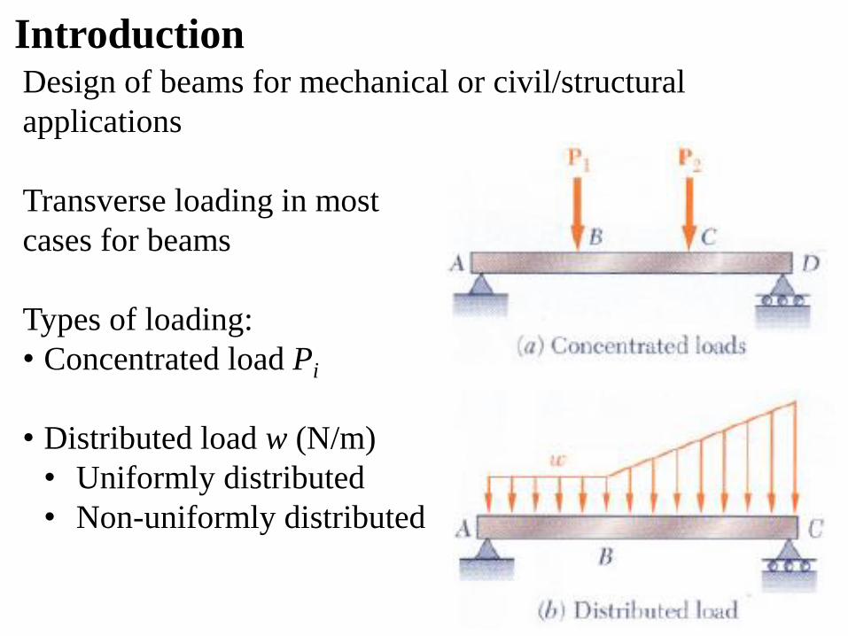
Design of beams for mechanical or civil/structural
applications
Transverse loading in most
cases for beams
Types of loading:
• Concentrated load Pi
• Distributed load w (N/m)
• Uniformly distributed
• Non-uniformly distributed
Introduction
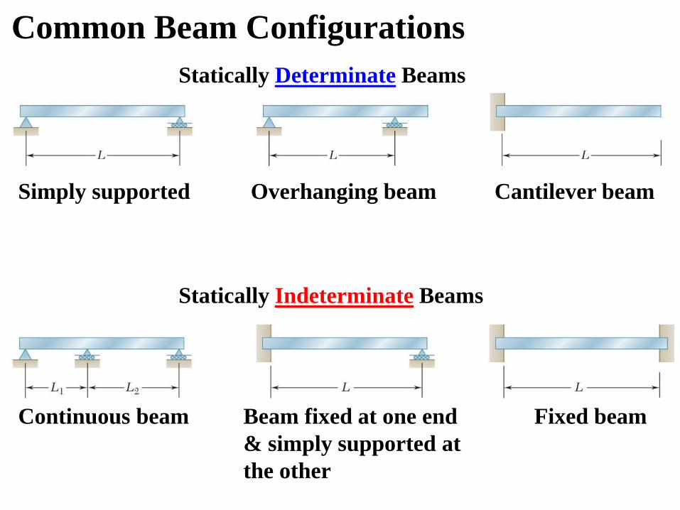
Common Beam Configurations
Simply supported Overhanging beam Cantilever beam
Continuous beam Fixed beam
Statically Determinate Beams
Statically Indeterminate Beams
Beam fixed at one end
& simply supported at
the other
Example: a simply supported beam with
two transverse loading forces of P1
& P2 and uniformly distributed load w
At an arbitrary cross-section C, draw
body diagram (FBD) for each side:
• Internal shear force V (or V’) that
creates shear stress in cross-section C
• Bending moment M (or M’) that
creates normal stress in cross-section C
I moment of inertia for cross-section C
y Distance from the neutral surface
c Maximum distance from the neutral surface
Equilibrium Analysis for Beam under
Transverse Loads
and 𝜎 = −𝑀𝑦
𝐼 𝜎𝑚𝑎𝑥 =
𝑀𝑐
𝐼
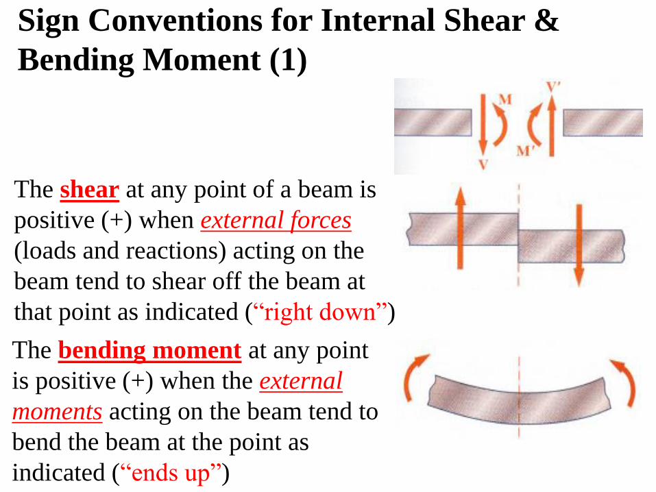
The bending moment at any point
is positive (+) when the external
moments acting on the beam tend to
bend the beam at the point as
indicated (“ends up”)
The shear at any point of a beam is
positive (+) when external forces
(loads and reactions) acting on the
beam tend to shear off the beam at
that point as indicated (“right down”)
Sign Conventions for Internal Shear &
Bending Moment (1)
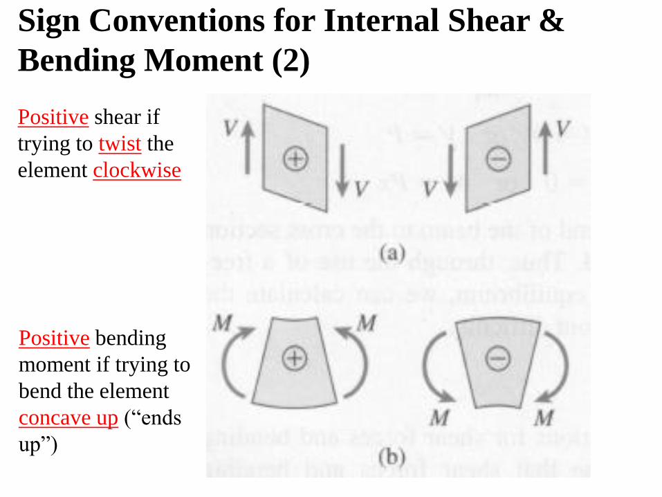
Positive shear if
trying to twist the
element clockwise
Positive bending
moment if trying to
bend the element
concave up (“ends
up”)
Sign Conventions for Internal Shear &
Bending Moment (2)
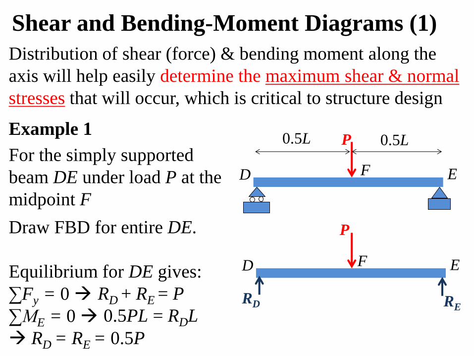
Shear and Bending-Moment Diagrams (1)
Example 1
For the simply supported
beam DE under load P at the
midpoint F
Distribution of shear (force) & bending moment along the
axis will help easily determine the maximum shear & normal
stresses that will occur, which is critical to structure design
P 0.5L 0.5L
D E F
Draw FBD for entire DE.
Equilibrium for DE gives:
∑Fy = 0
∑ME = 0
RD = RE = 0.5P
D E F
RD RE
P
RD + RE = P
0.5PL = RDL
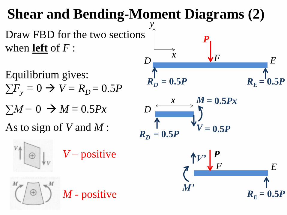
Draw FBD for the two sections
when left of F :
Equilibrium gives:
∑Fy = 0
∑M = 0
As to sign of V and M :
V – positive
M - positive
E
P
RE = 0.5P
F
M’
V’
x
y Shear and Bending-Moment Diagrams (2)
D
RD = 0.5P
x M
V = 0.5P
= 0.5Px
D E F
RD = 0.5P RE = 0.5P
P
V = RD = 0.5P
M = 0.5Px
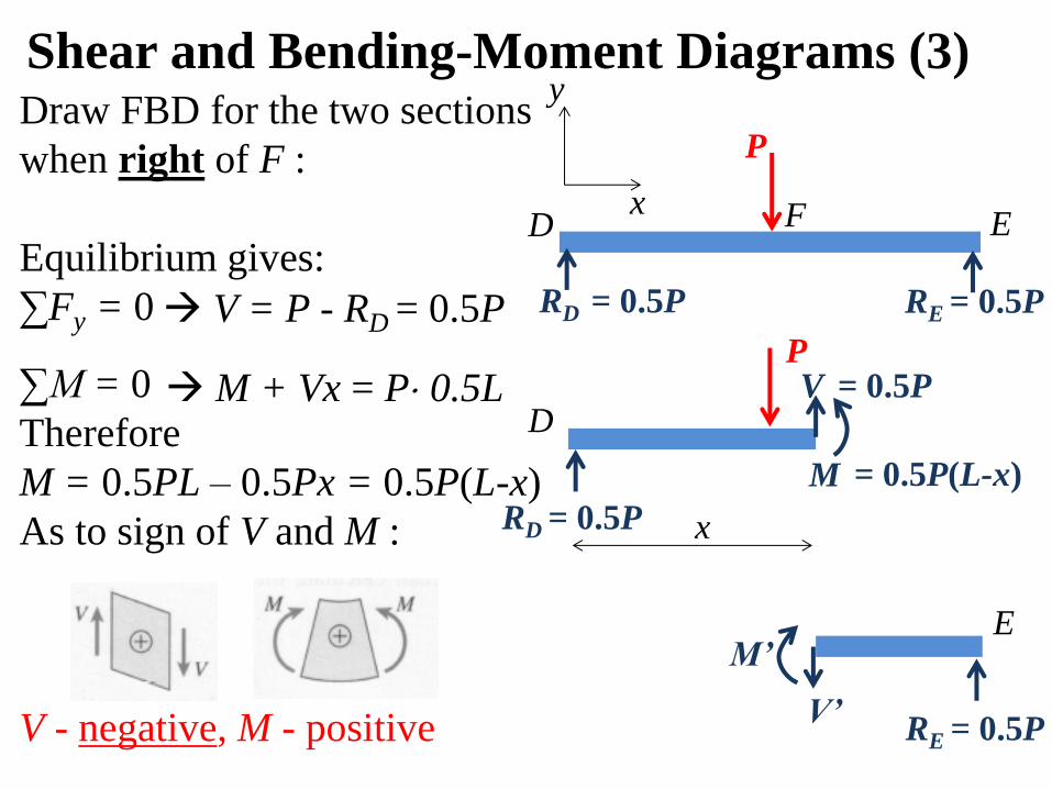
Shear and Bending-Moment Diagrams (3) Draw FBD for the two sections
when right of F :
Equilibrium gives:
∑Fy = 0
∑M = 0
Therefore
M = 0.5PL – 0.5Px = 0.5P(L-x)
As to sign of V and M :
V - negative, M - positive
= 0.5P D
P
RD = 0.5P
M
V
x
= 0.5P(L-x)
x
y
D E F
RD = 0.5P RE = 0.5P
P
V = P - RD = 0.5P
M + Vx = P 0.5L
E
RE = 0.5P V’
M’
0.25PL
0.5L L
0.5P
-0.5P 0.5L L
V
x 0
Shear Diagram
M
x 0
Moment Diagram
P 0.5L 0.5L
D E F
V = 0.5P
M = 0.5Px
V = -0.5P
To the left of F
To the right of F
To the left of F
To the right of F M = 0.5P(L-x)
Shear and Bending-Moment Diagrams (4)
M
x
0.25PL
0.5L L 0
Moment Diagram
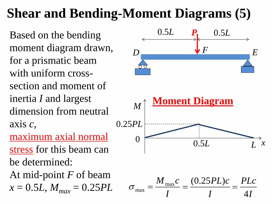
Based on the bending
moment diagram drawn,
for a prismatic beam
with uniform cross-
section and moment of
inertia I and largest
dimension from neutral
axis c,
maximum axial normal
stress for this beam can
be determined:
At mid-point F of beam
x = 0.5L, Mmax = 0.25PL I
cM maxmax
Shear and Bending-Moment Diagrams (5)
P 0.5L 0.5L
D E F
I
PLc
I
cPL
4
)25.0(
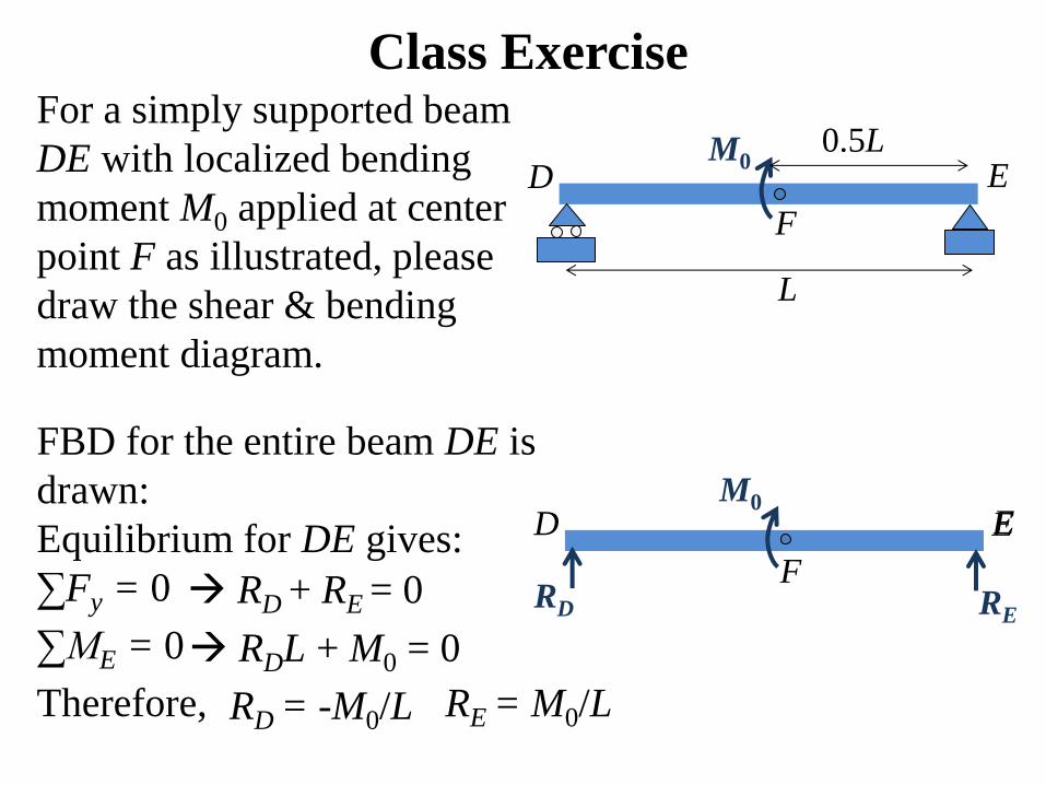
For a simply supported beam
DE with localized bending
moment M0 applied at center
point F as illustrated, please
draw the shear & bending
moment diagram.
Class Exercise
L
D E
FBD for the entire beam DE is
drawn:
Equilibrium for DE gives:
∑Fy = 0
∑ME = 0
Therefore,
M0 0.5L
F
D E
RD RE
E M0
F RD + RE = 0
RDL + M0 = 0
RD = -M0/L RE = M0/L
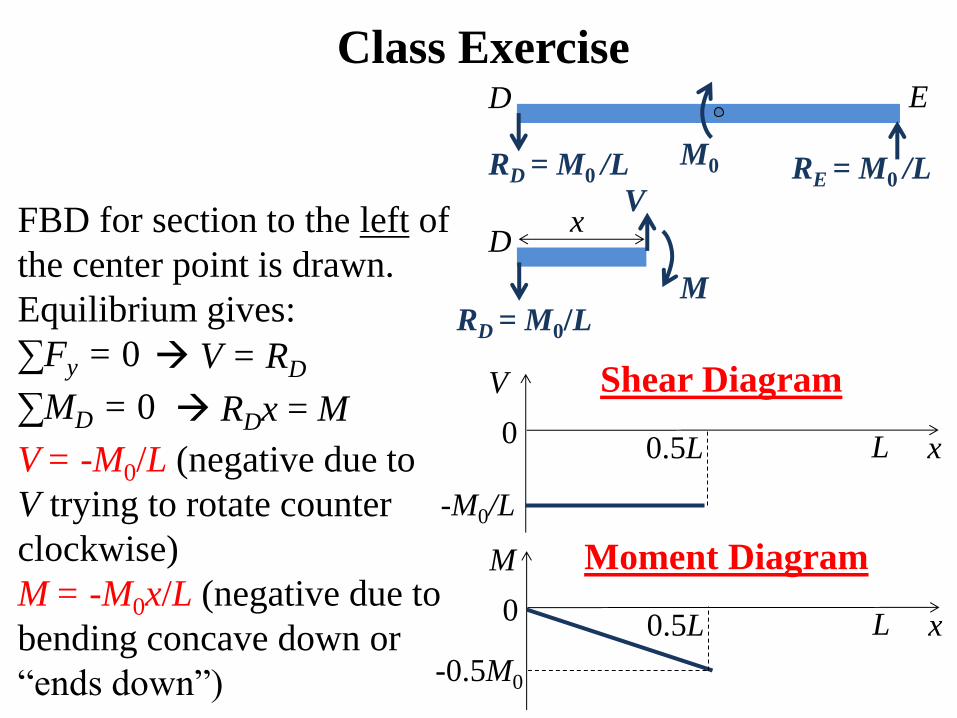
Class Exercise
FBD for section to the left of
the center point is drawn.
Equilibrium gives:
∑Fy = 0
∑MD = 0
V = -M0/L (negative due to
V trying to rotate counter
clockwise)
M = -M0x/L (negative due to
bending concave down or
“ends down”)
D E
RD = M0 /L M0
V
x 0
Shear Diagram
-M0/L
0.5L L
M
x 0
Moment Diagram
-0.5M0
0.5L L
D
RD = M0/L
V
M
x
V = RD
RDx = M
RE = M0 /L
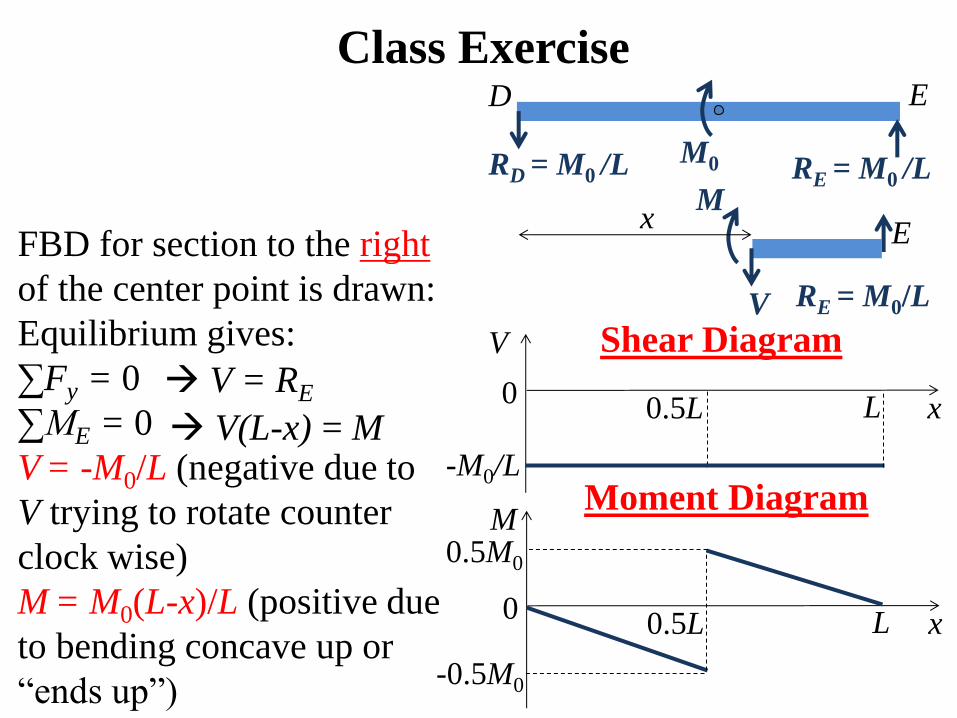
Class Exercise
FBD for section to the right
of the center point is drawn:
Equilibrium gives:
∑Fy = 0
∑ME = 0
V = -M0/L (negative due to
V trying to rotate counter
clock wise)
M = M0(L-x)/L (positive due
to bending concave up or
“ends up”)
V
x 0
Shear Diagram
-M0/L
0.5L L
D E
M0 RD = M0 /L RE = M0 /L
E
RE = M0/L V
M x
V = RE
V(L-x) = M
M
x 0
Moment Diagram
-0.5M0
0.5L L
0.5M0
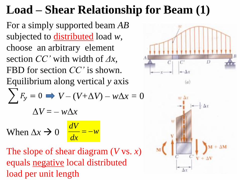
Load – Shear Relationship for Beam (1)
When x 0
For a simply supported beam AB
subjected to distributed load w,
choose an arbitrary element
section CC’ with width of Δx,
FBD for section CC’ is shown.
Equilibrium along vertical y axis
wdx
dV
The slope of shear diagram (V vs. x)
equals negative local distributed
load per unit length
𝐹𝑦 = 0 V – (V+ΔV) – wΔx = 0
ΔV = – wΔx
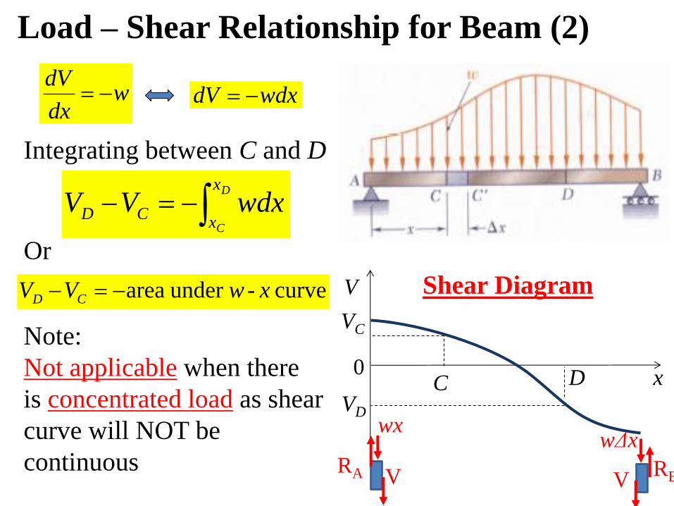
Integrating between C and D
Load – Shear Relationship for Beam (2)
D
C
x
xCD wdxVV
Or
V
x
VC
C 0
Shear Diagram
D
VD
curve -under area xwVV CD
Note:
Not applicable when there
is concentrated load as shear
curve will NOT be
continuous
wdx
dV wdxdV
RA
wx
V RB
wΔx
V
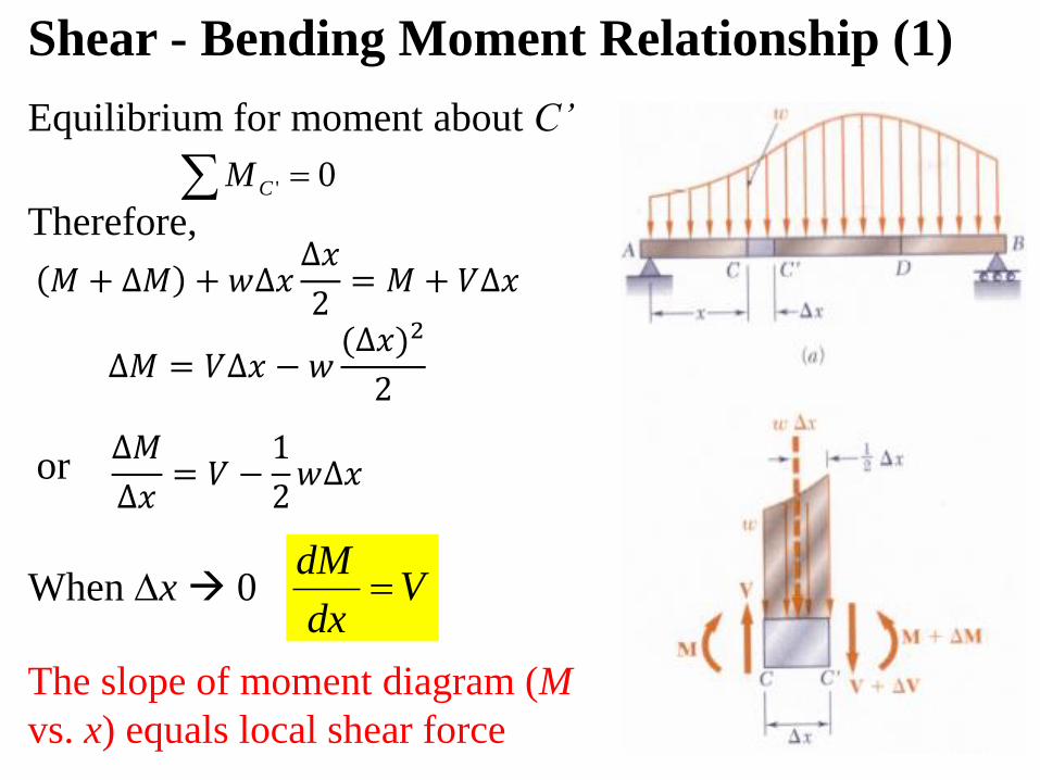
Shear - Bending Moment Relationship (1)
or
Equilibrium for moment about C’
0' CM
Therefore,
Vdx
dMWhen x 0
The slope of moment diagram (M
vs. x) equals local shear force
𝑀 + ∆𝑀 +𝑤∆𝑥∆𝑥
2= 𝑀 + 𝑉∆𝑥
∆𝑀 = 𝑉∆𝑥 − 𝑤(∆𝑥)2
2
∆𝑀
∆𝑥= 𝑉 −
1
2𝑤∆𝑥
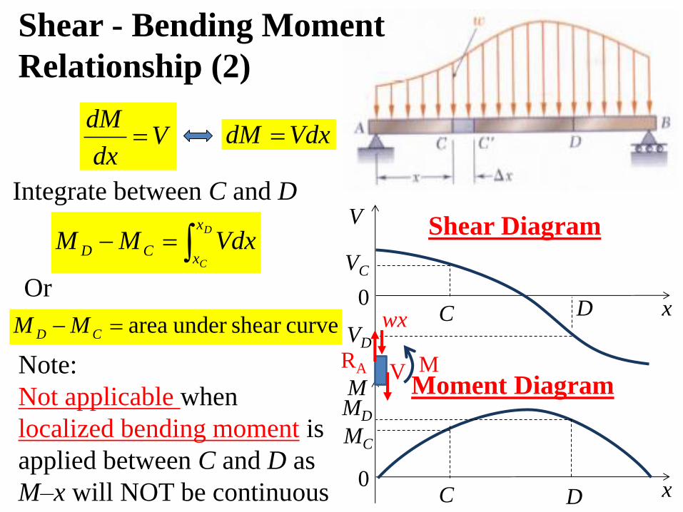
Integrate between C and D
Vdx
dM
D
C
x
xCD VdxMM
Or
curveshear under area CD MM
Note:
Not applicable when
localized bending moment is
applied between C and D as
M–x will NOT be continuous
V
x
VC
C 0
Shear Diagram
D
VD
M
x
MC
C 0
Moment Diagram
D
MD
VdxdM
Shear - Bending Moment
Relationship (2)
RA
wx
V M

Please draw the shear &
bending moment diagram
for a simply supported
beam with uniformly
distributed load w.
Class Example (1)
w
L
D E
Free body diagram for the
entire beam DE is drawn.
Equilibrium for DE gives:
∑Fy = 0
∑MD = 0
RD = RE = 0.5wL
D E
RD RE
w
RD + RE = wL
wL • 0.5L= REL
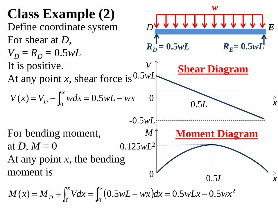
Class Example (2) Define coordinate system
For shear at D,
VD = RD = 0.5wL
It is positive.
At any point x, shear force is
V
x
0.5wL
0
Shear Diagram
-0.5wL
wxwLwdxVxVx
D 5.0)(0
M
x 0
0.125wL2
Moment Diagram For bending moment,
at D, M = 0
At any point x, the bending
moment is
2
005.05.05.0)( wxwLxdxwxwLVdxMxM
xx
D
0.5L
0.5L
D E
RD = 0.5wL RE= 0.5wL
w
E
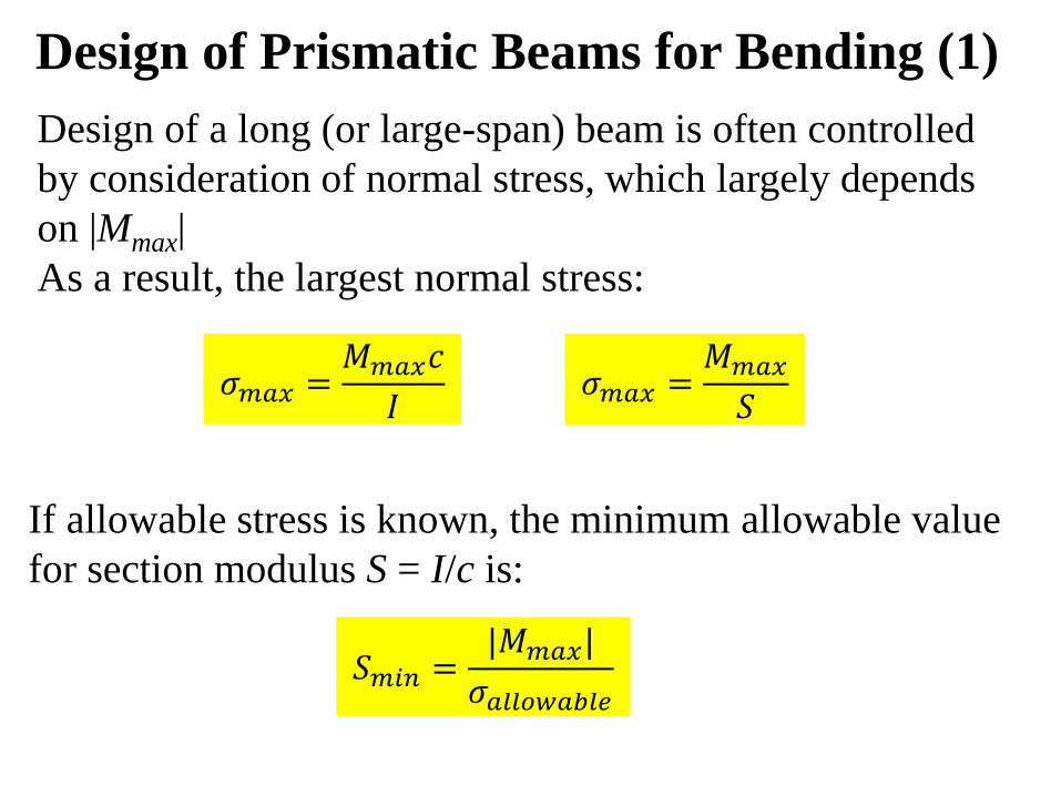
Design of Prismatic Beams for Bending (1)
Design of a long (or large-span) beam is often controlled
by consideration of normal stress, which largely depends
on |Mmax|
As a result, the largest normal stress:
If allowable stress is known, the minimum allowable value
for section modulus S = I/c is:
𝜎𝑚𝑎𝑥 =𝑀𝑚𝑎𝑥𝑐
𝐼 𝜎𝑚𝑎𝑥 =
𝑀𝑚𝑎𝑥𝑆
𝑆𝑚𝑖𝑛 =|𝑀𝑚𝑎𝑥|
𝜎𝑎𝑙𝑙𝑜𝑤𝑎𝑏𝑙𝑒
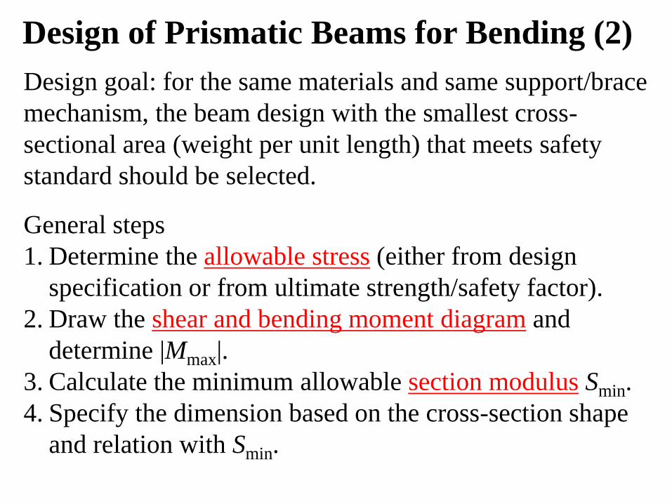
Design of Prismatic Beams for Bending (2)
Design goal: for the same materials and same support/brace
mechanism, the beam design with the smallest cross-
sectional area (weight per unit length) that meets safety
standard should be selected.
General steps
1. Determine the allowable stress (either from design
specification or from ultimate strength/safety factor).
2. Draw the shear and bending moment diagram and
determine |Mmax|.
3. Calculate the minimum allowable section modulus Smin.
4. Specify the dimension based on the cross-section shape
and relation with Smin.
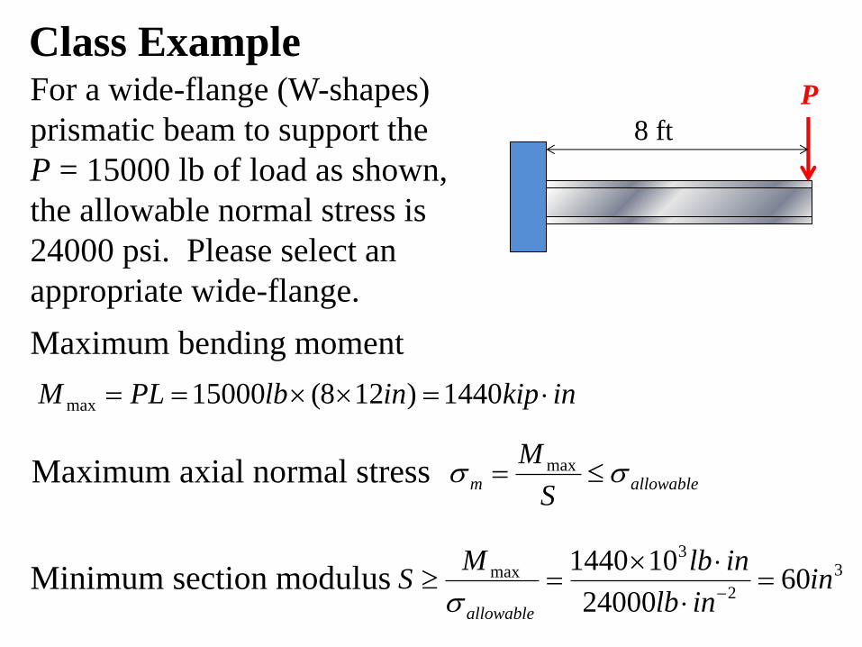
Class Example For a wide-flange (W-shapes)
prismatic beam to support the
P = 15000 lb of load as shown,
the allowable normal stress is
24000 psi. Please select an
appropriate wide-flange.
Maximum bending moment
P
8 ft
allowablemS
M max
inkipinlbPLM 1440)128(15000max
Maximum axial normal stress
3
2
3
max 6024000
101440in
inlb
inlbMS
allowable
Minimum section modulus
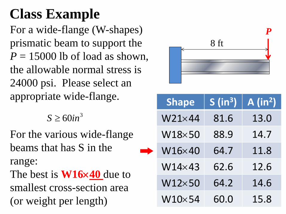
Class Example
For the various wide-flange
beams that has S in the
range:
The best is W1640 due to
smallest cross-section area
(or weight per length)
Shape S (in3) A (in2)
W2144 81.6 13.0
W1850 88.9 14.7
W1640 64.7 11.8
W1443 62.6 12.6
W1250 64.2 14.6
W1054 60.0 15.8
360inS
P
8 ft
For a wide-flange (W-shapes)
prismatic beam to support the
P = 15000 lb of load as shown,
the allowable normal stress is
24000 psi. Please select an
appropriate wide-flange.
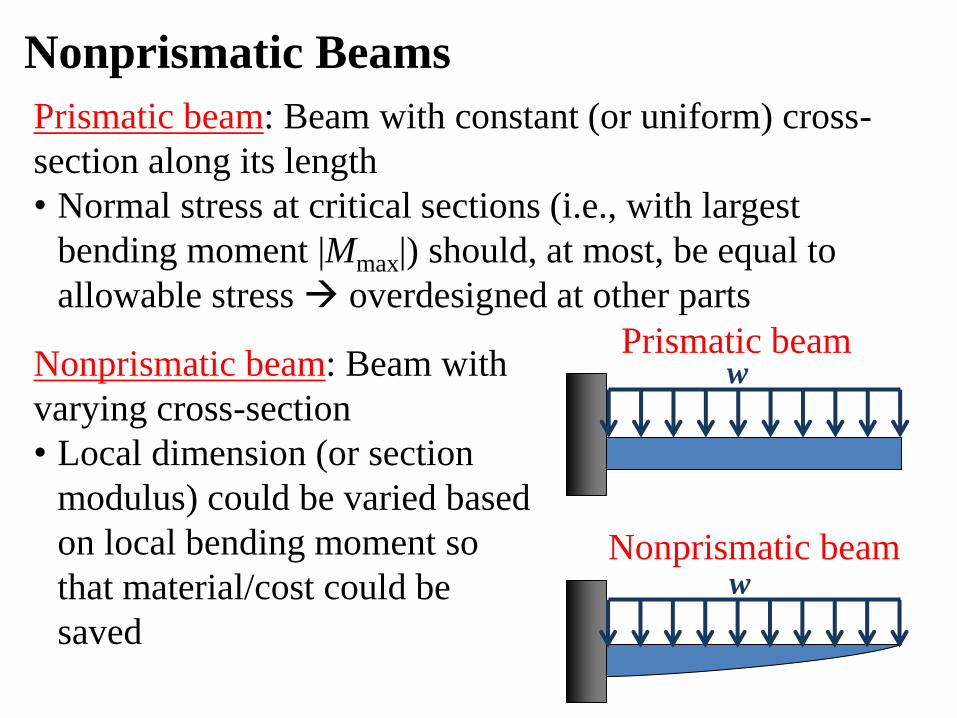
Nonprismatic Beams
Prismatic beam: Beam with constant (or uniform) cross-
section along its length
• Normal stress at critical sections (i.e., with largest
bending moment |Mmax|) should, at most, be equal to
allowable stress overdesigned at other parts
w
w
Prismatic beam
Nonprismatic beam
Nonprismatic beam: Beam with
varying cross-section
• Local dimension (or section
modulus) could be varied based
on local bending moment so
that material/cost could be
saved
EMA 3702 Mechanics & Materials Science Zhe Cheng (2018) 5 Beams for Bending
Homework 5.0
Read textbook chapter 5.1, 5.2, and 5.3 and give an
honor statement confirm reading
EMA 3702 Mechanics & Materials Science Zhe Cheng (2018) 5 Beams for Bending
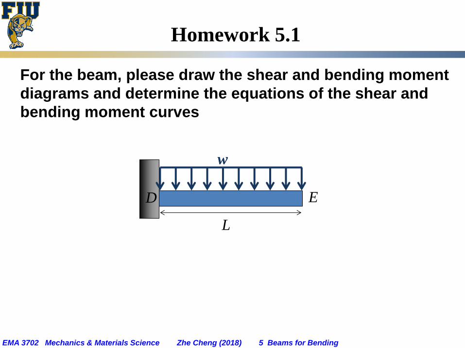
Homework 5.1
For the beam, please draw the shear and bending moment
diagrams and determine the equations of the shear and
bending moment curves
w
L
D E
EMA 3702 Mechanics & Materials Science Zhe Cheng (2018) 5 Beams for Bending
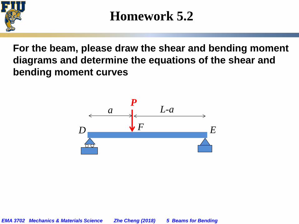
Homework 5.2
For the beam, please draw the shear and bending moment
diagrams and determine the equations of the shear and
bending moment curves
P a L-a
D E F
EMA 3702 Mechanics & Materials Science Zhe Cheng (2018) 5 Beams for Bending
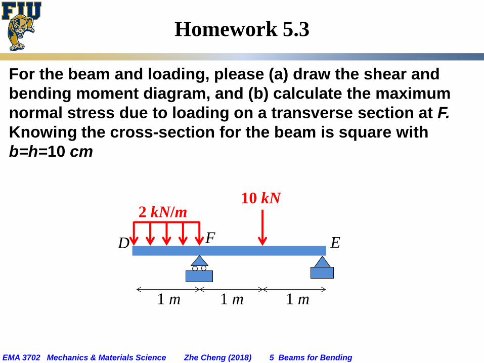
Homework 5.3
For the beam and loading, please (a) draw the shear and
bending moment diagram, and (b) calculate the maximum
normal stress due to loading on a transverse section at F.
Knowing the cross-section for the beam is square with
b=h=10 cm
1 m
D E F
2 kN/m 10 kN
1 m 1 m
EMA 3702 Mechanics & Materials Science Zhe Cheng (2018) 5 Beams for Bending
F
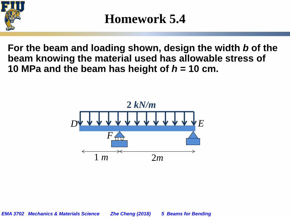
Homework 5.4
For the beam and loading shown, design the width b of the beam knowing the material used has allowable stress of 10 MPa and the beam has height of h = 10 cm.
1 m
D E
2m
2 kN/m


![Mechanics] MIT Materials Science and Engineering - Mechanics of Materials (Fall 1999)](https://img.pdfslide.net/doc/110x75/552532ce5503462a6f8b4744/mechanics-mit-materials-science-and-engineering-mechanics-of-materials-fall-1999.jpg)