Embed Size (px)
Citation preview
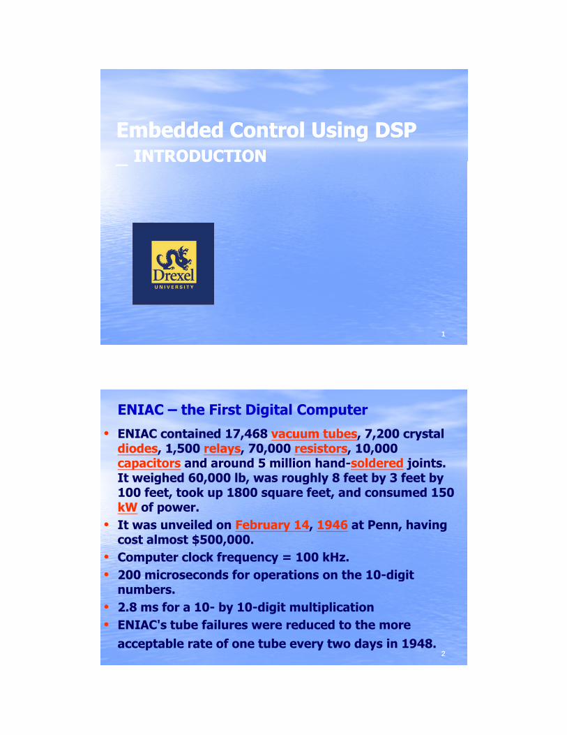
Embedded Control Using DSPEmbedded Control Using DSPINTRODUCTIONINTRODUCTION_ _ INTRODUCTIONINTRODUCTION
11
ENIAC – the First Digital Computer
• ENIAC contained 17,468 vacuum tubes, 7,200 crystal diodes, 1,500 relays, 70,000 resistors, 10,000 capacitors and around 5 million hand-soldered joints. It weighed 60,000 lb, was roughly 8 feet by 3 feet byIt weighed 60,000 lb, was roughly 8 feet by 3 feet by 100 feet, took up 1800 square feet, and consumed 150 kW of power.
• It was unveiled on February 14, 1946 at Penn, having cost almost $500,000.
• Computer clock frequency = 100 kHz.• 200 microseconds for operations on the 10 digit
22
• 200 microseconds for operations on the 10-digit numbers.
• 2.8 ms for a 10- by 10-digit multiplication• ENIAC's tube failures were reduced to the more
acceptable rate of one tube every two days in 1948.
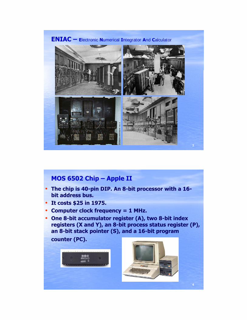
ENIAC – Electronic Numerical Integrator And Calculator
33
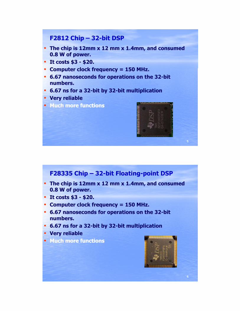
MOS 6502 Chip – Apple II
• The chip is 40-pin DIP. An 8-bit processor with a 16-bit address bus.
• It costs $25 in 1975.• Comp ter clock freq enc 1 MH• Computer clock frequency = 1 MHz.• One 8-bit accumulator register (A), two 8-bit index
registers (X and Y), an 8-bit process status register (P), an 8-bit stack pointer (S), and a 16-bit program counter (PC).
44
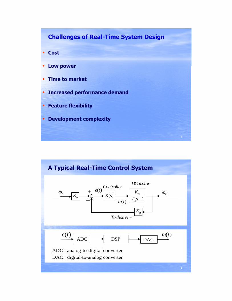
F2812 Chip – 32-bit DSP
• The chip is 12mm x 12 mm x 1.4mm, and consumed 0.8 W of power.
• It costs $3 - $20.• Comp ter clock freq enc 150 MH• Computer clock frequency = 150 MHz.• 6.67 nanoseconds for operations on the 32-bit
numbers. • 6.67 ns for a 32-bit by 32-bit multiplication• Very reliable•• Much more functionsMuch more functions
55
Much more functionsMuch more functions
F28335 Chip – 32-bit Floating-point DSP
• The chip is 12mm x 12 mm x 1.4mm, and consumed 0.8 W of power.
• It costs $3 - $20.• Comp ter clock freq enc 150 MH• Computer clock frequency = 150 MHz.• 6.67 nanoseconds for operations on the 32-bit
numbers. • 6.67 ns for a 32-bit by 32-bit multiplication• Very reliable•• Much more functionsMuch more functions
66
Much more functionsMuch more functions
Challenges of Real-Time System Design
• Cost
• Low power• Low power
• Time to market
• Increased performance demand
fl ibili
77
• Feature flexibility
• Development complexity
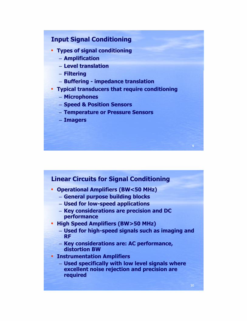
A Typical Real-Time Control System
K
Tm
1Kg K s( )
DC motorController
+ ωmωre t( )
T sm +1
Kg
g K s( )−
Tachometer
m t( )
e t( ) m t( )
88
DSPADC e t( )
DACm t( )
ADC: analog-to-digital converterDAC: digital-to-analog converter
Input Signal Conditioning
• Types of signal conditioning– Amplification– Level translation– Filtering– Buffering - impedance translation
• Typical transducers that require conditioning– Microphones– Speed & Position Sensors
T t P S
99
– Temperature or Pressure Sensors– Imagers
Linear Circuits for Signal Conditioning
• Operational Amplifiers (BW<50 MHz)– General purpose building blocks– Used for low-speed applications
Key considerations are precision and DC– Key considerations are precision and DC performance
• High Speed Amplifiers (BW>50 MHz)– Used for high-speed signals such as imaging and
RF– Key considerations are: AC performance,
distortion BW
1010
distortion BW• Instrumentation Amplifiers
– Used specifically with low level signals where excellent noise rejection and precision are required
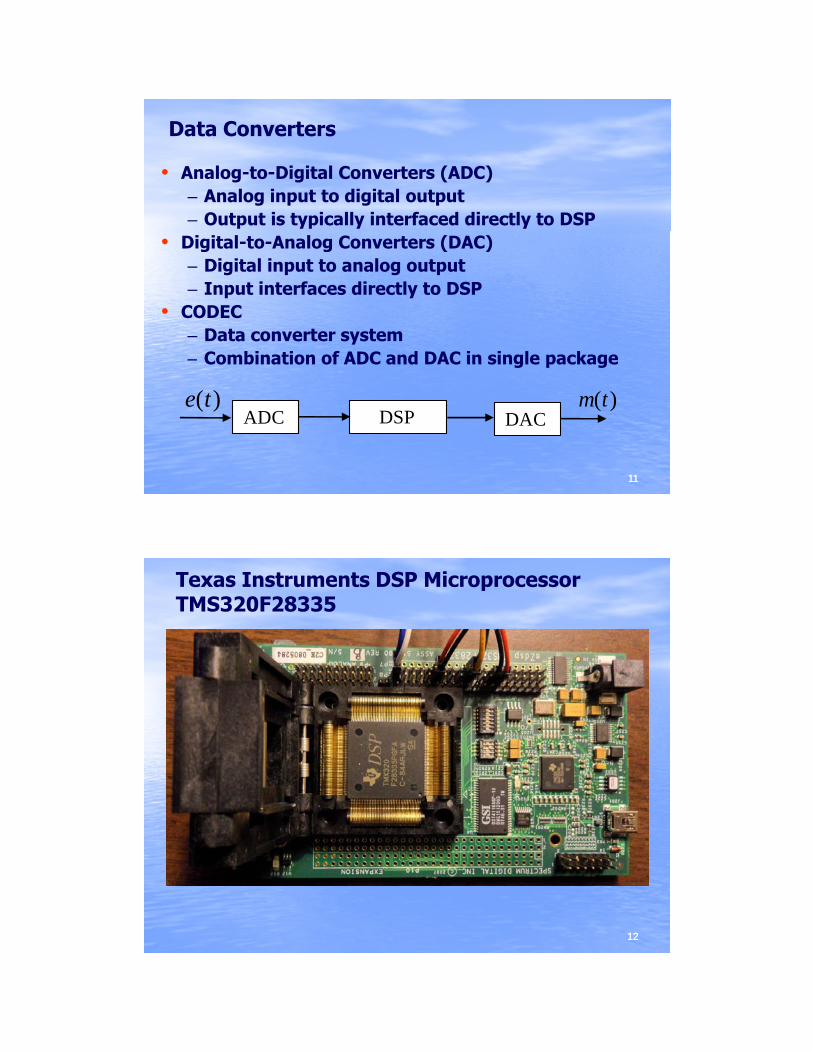
Data Converters
• Analog-to-Digital Converters (ADC)– Analog input to digital output– Output is typically interfaced directly to DSP
• Digital-to-Analog Converters (DAC)– Digital input to analog output– Input interfaces directly to DSP
• CODEC– Data converter system– Combination of ADC and DAC in single package
1111
Combination of ADC and DAC in single package
DSP ADC e t( )
DACm t( )
Texas Instruments DSP Microprocessor TMS320F28335
1212
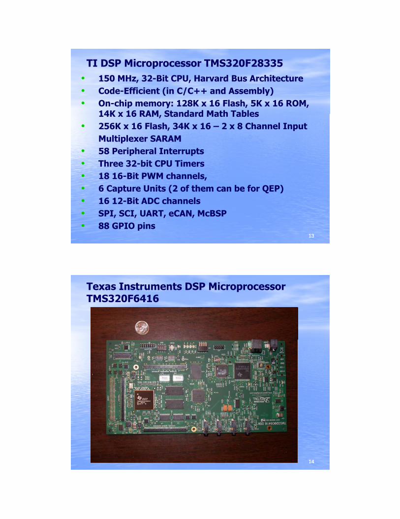
TI DSP Microprocessor TMS320F28335• 150 MHz, 32-Bit CPU, Harvard Bus Architecture• Code-Efficient (in C/C++ and Assembly)• On-chip memory: 128K x 16 Flash, 5K x 16 ROM,
14K x 16 RAM Standard Math Tables14K x 16 RAM, Standard Math Tables• 256K x 16 Flash, 34K x 16 – 2 x 8 Channel Input
Multiplexer SARAM• 58 Peripheral Interrupts• Three 32-bit CPU Timers• 18 16-Bit PWM channels,
1313
18 16 Bit PWM channels, • 6 Capture Units (2 of them can be for QEP)• 16 12-Bit ADC channels• SPI, SCI, UART, eCAN, McBSP• 88 GPIO pins
Texas Instruments DSP Microprocessor TMS320F6416
1414
TI DSP Microprocessor TMS320F6416
• Highest-Performance Fixed-Point (DSPs)− Eight 32-Bit Instructions/Cycle− Up to 720MHz Clock Rates− Up to 28 Operations/Cycle− Up to 28 Operations/Cycle − Up to 5760 MIPS
• Advanced Very Long Instruction WordEight Highly Independent Functional Units:Six ALUs (32-/40-Bit), Each Supports Single 32-Bit, Dual 16-Bit, or Quad 8-Bit Arithmetic per Clock Cycle Two Multipliers Support Four 16 x 16-Bit Multiplies (32-Bit
1515
Two Multipliers Support Four 16 x 16 Bit Multiplies (32 Bit Results) per Clock Cycle or Eight 8 x 8-Bit Multiplies (16-Bit Results) per Clock Cycle64 32-Bit General-Purpose Registers
TI DSP Microprocessor TMS320F6416
• L1/L2 Memory Architecture• Two External Memory Interfaces (EMIFs)
One 64-Bit (EMIFA), One 16-Bit (EMIFB) Gl l I t f t A h M i (SRAM dGlueless Interface to Asynchronous Memories (SRAM and EPROM) and Synchronous Memories (SDRAM, SBSRAM, ZBT SRAM, and FIFO) 1280M-Byte Total Addressable External Memory Space
• Three Multichannel Buffered Serial Ports:− Serial-Peripheral-Interface (SPI)− Direct Interface to T1/E1, MVIP, SCSA Framers
1616
Direct Interface to T1/E1, MVIP, SCSA Framers− AC97 Interface
• 32-Bit/33-MHz, 3.3-V PCI Master/Slave Interface
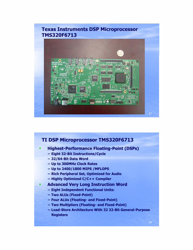
Texas Instruments DSP Microprocessor TMS320F6713
1717
TI DSP Microprocessor TMS320F6713
• Highest-Performance Floating-Point (DSPs)− Eight 32-Bit Instructions/Cycle− 32/64-Bit Data Word− Up to 300MHz Clock Rates− Up to 300MHz Clock Rates− Up to 2400/1800 MIPS /MFLOPS− Rich Peripheral Set, Optimized for Audio− Highly Optimized C/C++ Compiler
• Advanced Very Long Instruction Word− Eight Independent Functional Units:− Two ALUs (Fixed-Point)
1818
− Two ALUs (Fixed-Point)− Four ALUs (Floating- and Fixed-Point)− Two Multipliers (Floating- and Fixed-Point)− Load-Store Architecture With 32 32-Bit General-Purpose
Registers
TI DSP Microprocessor TMS320F6713
• 32-Bit External Memory Interface (EMIF)− Glueless Interface to SRAM, EPROM, Flash, SBSRAM, and
SDRAM− 512M-Byte Total Addressable External Memory Space− 512M-Byte Total Addressable External Memory Space
• Two Multichannel Buffered Serial Ports:− Serial-Peripheral-Interface (SPI)− High-Speed TDM Interface− AC97 Interface
1919
Digital Controller Design _ 1Digital Controller Design _ 1
( )m k
T( )K z
u t( ). . .z o h
( )r k( )pG s
( )y t
cC
( )e k
y k( )
T( )( )R z
c
1( )y k
1( )Y z
( )m k( )r k ( )e k
Sampled-data feedback control system
2020
1( )y ky k( )
( )m k( )K z
( )r k
( )R z
( )e k
1( )Y z
( )G z
Its discrete-time equivalent
Digital Controller Design _ 2Digital Controller Design _ 2
G sp ( )TE s( )R s( ) +
−
Y s( )E z( ) M z( )
digialcontroller plant
DAC( )K z
+
−
E z( ) M z( )
digialcontroller
G z( )R z( ) Y z( )( )K z
2121
Find so that the closedFind so that the closed--loop system loop system has a desired performance.has a desired performance.
( )K z
Digital Controller ImplementationDigital Controller Implementation
1 20 1 2
1 21 2
( )( )( ) 1
a a z a zM zK z
E z b z b z
− −
− −
+ += =+ +
)()()()(
)()()()(2
21
1
22
110
zXzbzXzbzEzX
zXzazXzazXazM
⋅−⋅−=
⋅+⋅+=−−
−−
)2()1()()( 210 −⋅+−⋅+= kxakxakxakm
1 2( ) 1E z b z b z+ +
2222
)2()1()()()()()()(
21
210
−⋅−−⋅−= kxbkxbkekx
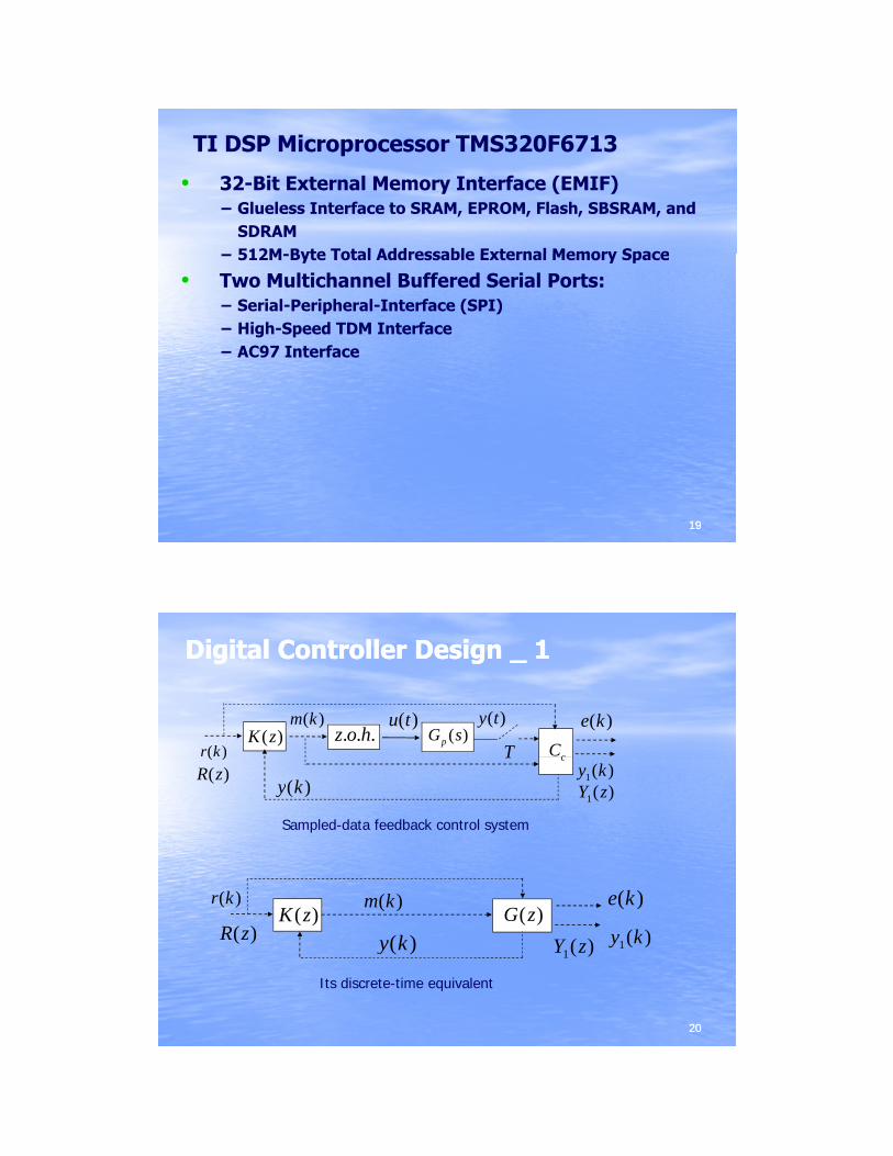
Speed Control _ F2812Speed Control _ F2812
2323
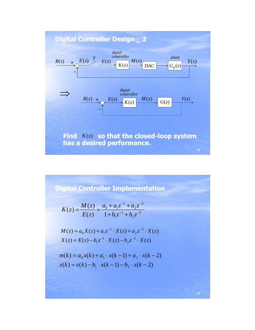
Position Control _ F2812Position Control _ F2812
2424
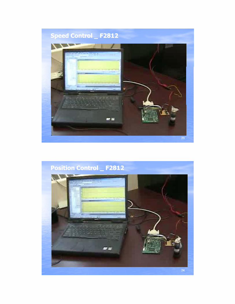
Sinusoidal Tracking _ F2812Sinusoidal Tracking _ F2812
2525
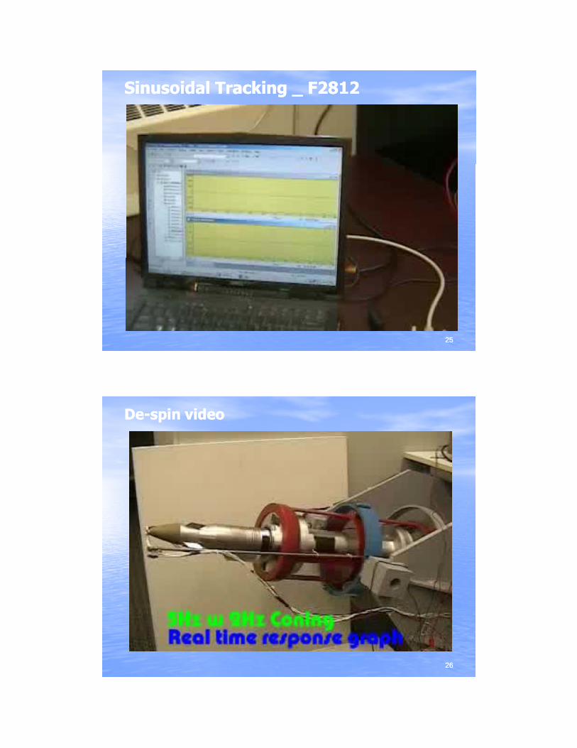
DeDe--spin videospin video
2626
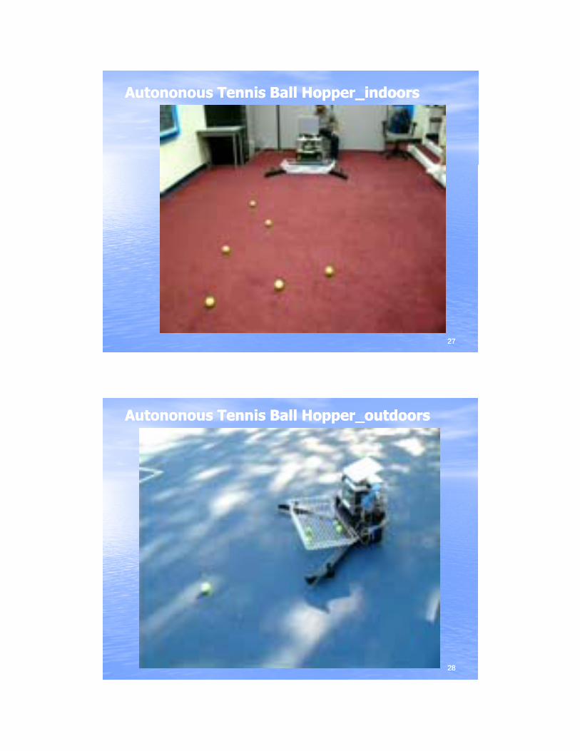
Autononous Tennis Ball HopperAutononous Tennis Ball Hopper__indoorsindoors
2727
Autononous Tennis Ball HopperAutononous Tennis Ball Hopper__outdoorsoutdoors
2828
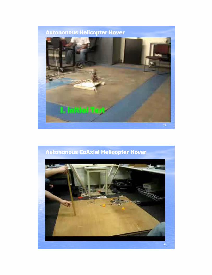
AutononousAutononous Helicopter HoverHelicopter Hover
2929
AutononousAutononous CoAxialCoAxial Helicopter HoverHelicopter Hover
3030
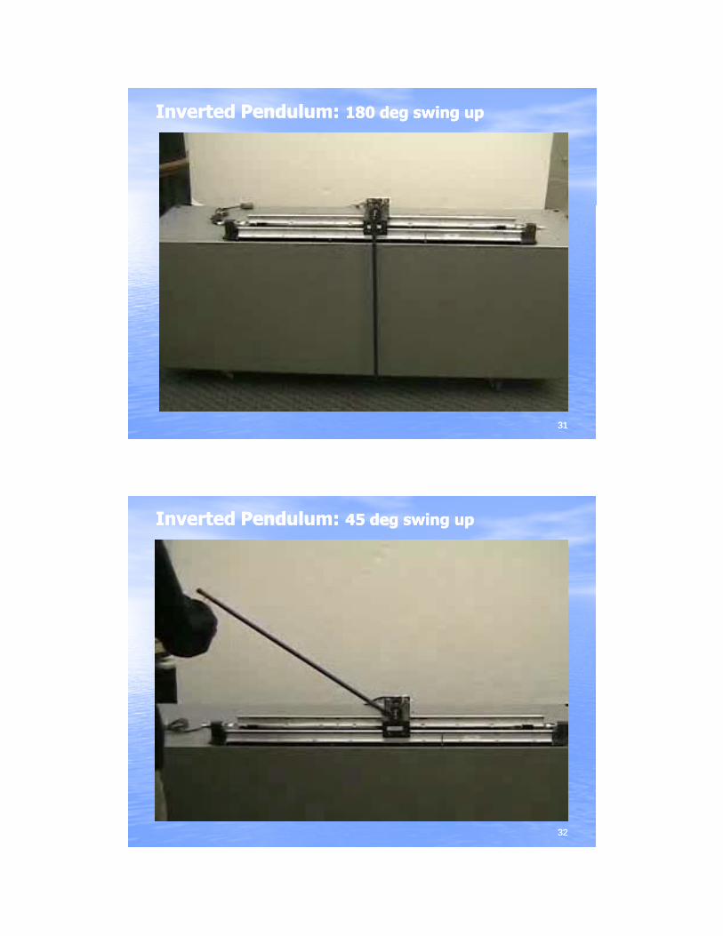
Inverted Pendulum:Inverted Pendulum: 180 deg swing up180 deg swing up
3131
Inverted Pendulum:Inverted Pendulum: 45 deg swing up45 deg swing up
3232
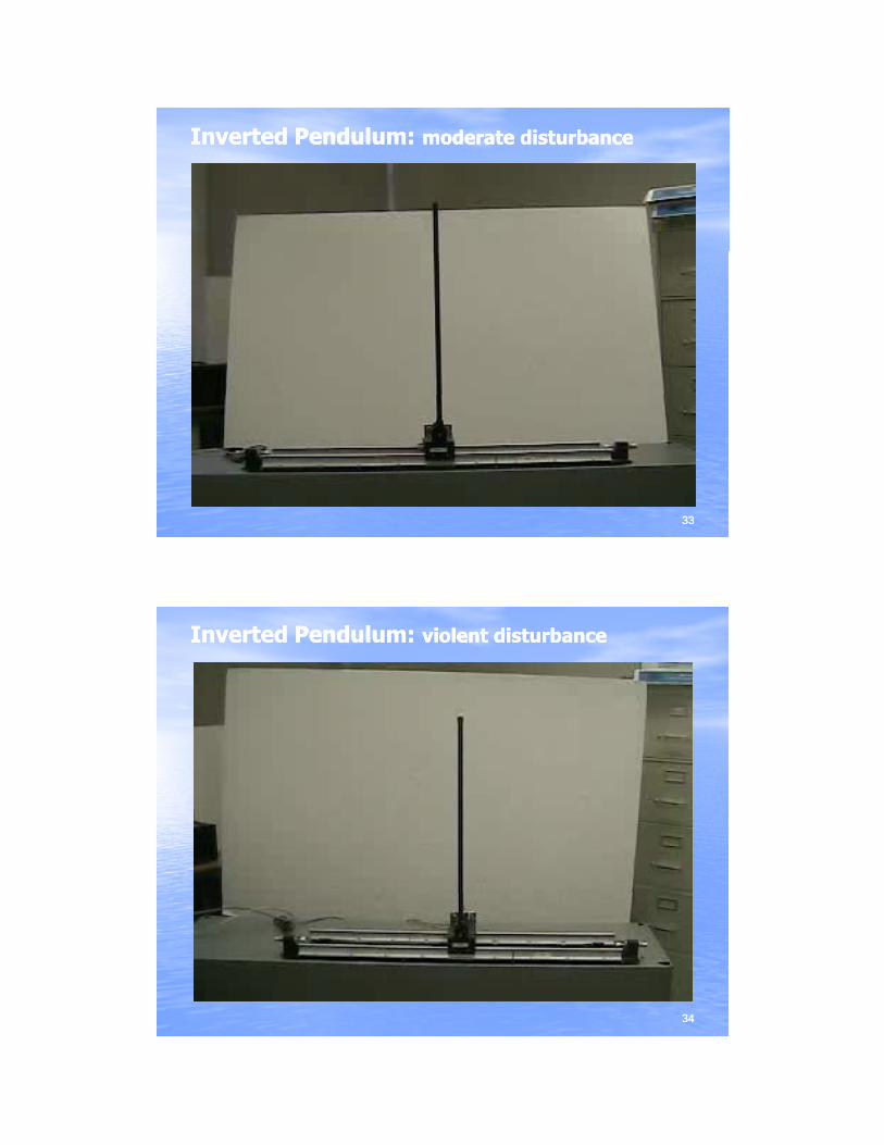
Inverted Pendulum:Inverted Pendulum: moderate disturbancemoderate disturbance
3333
Inverted Pendulum:Inverted Pendulum: violent disturbanceviolent disturbance
3434