Embed Size (px)
Citation preview
Basic parameters
• Full duplex IEEE 802.3 10 Mb/s Ethernet• AT89C51RD2 / ED2 microcontroller• 64 kByte In-System Programmable FLASH ROM • 32 kByte SRAM + 1 kByte internal MCU SRAM • 2 kByte In-System programmable EEPROM • Supports TCP Server, Client, Client/Server, UDP • 8 I/O pins accessible over the TCP/IP (NVT protocol) • Everything under opened RFC standard and well
documented• Web51 development system, applications written in
assembler, many examples available. • Web51-C development system, applications written in
ANSI C (Keil µC or SDCC), solved examples, library for Keil µC SNMP available.
• Virtual serial port for Windows 2000 & XP FREE to download
Ready to use Firmware:
• ConverterTCP/IP (UDP/IP) Ethernet to RS-232 converter with RS-485 support.- 8TCP controlled binary inputs/outputs
• Web51 Home Web Control WWW interface, simple TCP/IP – RS-232 converter
• MetexMeasuring devices remote control
• SNMP I/O Thermometer8x Input, 8x Output, 1-Wire thermometer, SNMP traps.
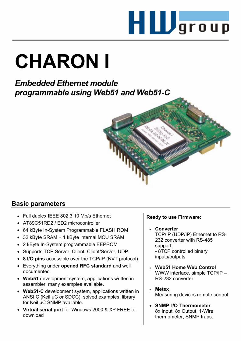
CHARON I Embedded Ethernet moduleprogrammable using Web51 and Web51-C

Charon I –RS232-Ethernet conversion module HW group
page 2 / 324.11.2004 HW group, Prague, Czech Republic, Europe www.HW-group.com
PIN NAME FUNCTION I/O PIN optional TPO+, TPO- 10Base -T Differential Outputs OUT 1,2 - TPI+, TPI- 10Base -T Differential Inputs IN 4,3 - LINK 10Base- T Link or RX Indicator OUT 5 -
Ethe
rnet
GND GND for Ethernet shield GND 6 - RxD P3-0 pin – Receive Data IN 7 * TxD P3-1 pin – Transmit Data OUT 8 * CTS P3-3 pin (INT1) - Clear to Send IN 9 - R
S-23
2
RTS P3-5 pin (T1) - Request to Send OUT 10 - PSEN Connect to GND before FW programming IN 11 * +5V Power +5V DC 15-80 mA PWR 12 - P1 (P1.0 .. P1.7) Direct 8. bit I/O port P1 I/O 13..20 - INT0 P3-2 pin (INT0) - universal pin I/O 21 - T0 P3-4 pin (T1) – universal pin I/O 22 ** RST RESET module (H = reset) I/O 23 - GND Main ground GND 24 -
*) – used for FirmWare programming over RS-232 using the „Flip“ application **) – start the RS-232 Setup mode if connected to GND during power-up and reset. 9600 8N1
1
12
13
24

Charon I –RS232-Ethernet conversion module HW group
page 3 / 324.11.2004 HW group, Prague, Czech Republic, Europe www.HW-group.com
HW parametersPower supply 5V DC / 60 mA I/O pins 14 = 4 (RS232) + 8 (P1) + 2 Dimension 44 x 35 x 12 mm (L x W x H ) RAM / EEPROM 32 KB / 2 KB (MCU internal) Temperature Operating: -5 – 50 °C RTL8019 EEPROM 256B (93C46) – optionally Ethernet 10BaseT - 802.3 MCU Xtal 18.432 MHz (X2 mode) Serial port TTL levels RxD,TxD,RTS,CTS Power-on reset YES – 10% tolerance Programming ISP over RS-232 (Atmel Flip SW) WATCHDOG MCU internal WD only
• Each module has its own unique MAC address (written on the label). • All modules are tested for at least 24 hours.• The module is supplied with firmware, which can be erased and replaced for your application.
Features• Ready-to-go Serial-to-Ethernet module to network enable any serial (RS-232/ RS422/ 485
TTL) device.• 10 Mb/s Ethernet, 115.2kBd serial interface• Supports TCP Server, TCP Client, TCP Client/Server, UDP• Virtual Serial Port for Windows 2000 and higher free (RFC2217 compatible = remote
baudrate variable, I/O pins status..).• 8x I/O pin accessible over the TCP/IP (NVT protocol).• Single +5V input, 0.3 W low power consumption• Everything under opened RFC standard and well documented.• A lot of support PC programming examples ( MS Visual Basic, Delphi, Borland C++, JAVA,
PHP and others) and technical background..
• Module can be programmed using:• x51 ASM (Web51)• ANSI C (Keil from SDCC - Web51-C)
• Charon I is pin compatible with the Charon II module (fully customer programmable module with RTOS in the ANSI C, it's an open source project).
Accessories• External Ethernet transformer:
• LF1S022 - RJ45 connector with integrated transformer • YCL20F001N or FB2022 Ethernet signal transformer
• Charon I – Web51 Development Kit (simple and cheap kit) • Charon I & II Development Board (development boars with Ethernut Charon II peripherals)

Charon I –RS232-Ethernet conversion module HW group
page 4 / 324.11.2004 HW group, Prague, Czech Republic, Europe www.HW-group.com
FirmwareThere are some finished firmwares free for use with the Charon I module. You can find detailed descriptions of available Firmware on their respective pages. Here we have abbreviated FW descriptions. You can download the HEX files for the module on the Charon I main page - Download chapter.
Converter FW Default loaded FW for easy-to-use serial port and 8x I/O pins to the TCP/IP and UDP/IP protocols, support for NVT control according to RFC2217.
• RS-232 Setup (standard serial terminal)• UDP Setup on a local segment using the Hercules
SETUP utility.• TCP/IP Setup - Remote terminal configuration via
TCP/IP.Full/half duplex mode, direction switching for RS485. Any speed from 50 to 115200 Bd, all settings of parity, stop bits, etc. Support for 9-bit data transfers.
This is the default application burned in every Charon module.
SNMP Thermometer FW Demo of SNMP control options. Custom definition of MIB is not available; it is only a demo of a remotely controlled application and configuration over SNMP. 1 thermometer, 8 Inputs, 8 Outputs, LCD display etc connection demo. Its possible to program a lot of SNMP applications in C language and our development kit „Web51 ANSI C – SNMP“ contains many examples, which helps you to get started quickly. The most advanced application is „SNMP I/O Thermometer“, which you can use together with the JAVA application „Thermometer“, instead of a common SNMP client, it controls a serial RS-232 link, up to 32 binary inputs/outputs and 4 1-Wire thermometers
Home Web Control FW The Charon I module with this firmware controls the RS-232 line, 8x inputs and 8x outputs, LCD display and up to 4 one-wire thermometers via Ethernet network, using a Telnet or Web browser application. We recommend you use the Charon I Development Kit for testing and using the firmware. You can use the Charon I&II DB, which contains shifted peripherals and is normally distributed with the Charon II module. The module is a small WWW server, so it has its own IP address and it provides standard WWW service on port 80. You can then see the I/O ports status, the temperatures and so on. You can also set the password (in the RS-232 line setup) for making changes on the outputs ports.

Charon I –RS232-Ethernet conversion module HW group
page 5 / 324.11.2004 HW group, Prague, Czech Republic, Europe www.HW-group.com
Getting started in 15 steps Quick introduction to the Charon I application module with “Ethernet – RS-232/485 converter”firmware. This chapter describes how to connect the module to the Ethernet and debug your first application in minutes.
1. Power Supply You will need an unregulated power supply matching your local mains. It should supply 9-15V DC, at least 150 mA , on a standard 2.1 mm barrel connector. Power polarity is specified on the board. ( GND -(o- Vcc )
2. RS-232 The serial port should be connected to a serial port on the control unit. Connect the Charon I DK with a PC by RS-232 using the supplied prolong cable Cannon 9 - a 1:1 cable.
3. Ethernet Use a twisted pair cable to connect PortStore's RJ-45 connector to the hub or switch. If you are not using a hub or switch, connect the PortStore device directly to the network adapter using a twisted pair cross cable.
The Ethernet connection• HUB, Switch, Bridge : Direct TP cable (called PATCH cable)• PC or any other device: Twisted cable (The connectors have
different wire colors and switched TX and RX wires.)
Figure 2: Charon I Development Kit
Charon I –RS232-Ethernet conversion module HW group
page 6 / 324.11.2004 HW group, Prague, Czech Republic, Europe www.HW-group.com
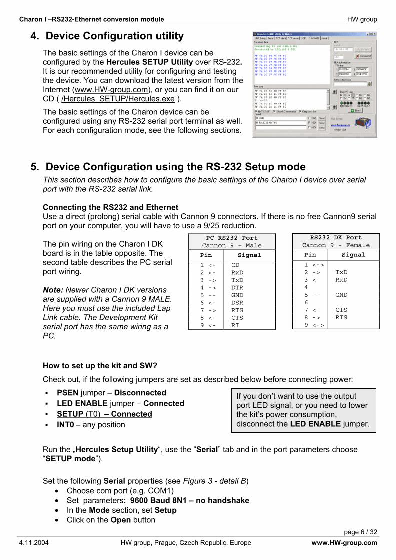
4. Device Configuration utility The basic settings of the Charon I device can be configured by the Hercules SETUP Utility over RS-232.It is our recommended utility for configuring and testing the device. You can download the latest version from the Internet (www.HW-group.com), or you can find it on our CD ( /Hercules_SETUP/Hercules.exe ).The basic settings of the Charon device can be configured using any RS-232 serial port terminal as well. For each configuration mode, see the following sections.
5. Device Configuration using the RS-232 Setup mode This section describes how to configure the basic settings of the Charon I device over serial port with the RS-232 serial link.
Connecting the RS232 and EthernetUse a direct (prolong) serial cable with Cannon 9 connectors. If there is no free Cannon9 serial port on your computer, you will have to use a 9/25 reduction.
The pin wiring on the Charon I DK board is in the table opposite. The second table describes the PC serial port wiring.
Note: Newer Charon I DK versions are supplied with a Cannon 9 MALE. Here you must use the included Lap Link cable. The Development Kit serial port has the same wiring as a PC.
How to set up the kit and SW? Check out, if the following jumpers are set as described below before connecting power:
PSEN jumper – DisconnectedLED ENABLE jumper – ConnectedSETUP (T0) – ConnectedINT0 – any position
Run the „Hercules Setup Utility“, use the “Serial” tab and in the port parameters choose “SETUP mode”).
Set the following Serial properties (see Figure 3 - detail B)• Choose com port (e.g. COM1) • Set parameters: 9600 Baud 8N1 – no handshake• In the Mode section, set Setup• Click on the Open button
PC RS232 Port Cannon 9 – Male
Pin Signal
1 <- CD 2 <- RxD 3 -> TxD 4 -> DTR 5 -- GND 6 <- DSR 7 -> RTS 8 <- CTS 9 <- RI
RS232 DK Port Cannon 9 - Female
Pin Signal
1 <-> 2 -> TxD 3 <- RxD 4 5 -- GND 6 7 <- CTS 8 -> RTS 9 <->
If you don’t want to use the output port LED signal, or you need to lower the kit’s power consumption, disconnect the LED ENABLE jumper.

Charon I –RS232-Ethernet conversion module HW group
page 7 / 324.11.2004 HW group, Prague, Czech Republic, Europe www.HW-group.com
6. Power On – Using the “RS-232 Setup” Connect the power supply to the coaxial connector. When the PortStore is powered up correctly, the green power LED should light up.
You can see the listing of the basic settings in the Hercules SETUP utility on the Serial tab in main window.
Press <Enter> 3 times to finish listing and to display the command prompt. “WEB51>”
The displayed list shows a letter in front of each Setup command, which you have to use to change the different parameters.
For example, if you would like to change the IP address, just write „I192.168.6.15“ to the command line and press <enter>.
If you press just the Enter key, the whole list is displayed once more. After pressing Enter, the value is stored into EEPROM immediately, there is no need to save configuration.
Notes:
• HELP Type ? after the command for help. „I?“↵ or „&B?“↵• The backspace will work, if the terminal is set up well.
If you have set at least the basic parameters (such as IP, MASK, Gateway and serial port speed), disconnect the SETUP jumper on the development board and reset by pushing the on board button or typing “R: Reboot” in the Terminal Setup.
You don’t see command listings in your serial terminal? - Check the jumper T0 – SETUP position (shorted) - Check the power supply of the device (reset it by reset button) - Check your RS-232 Prolong cable- Check the serial terminal settings (9600 - 8N1 - No handshake)
Figure 3: Hercules SETUP Utility – Serial tab

Charon I –RS232-Ethernet conversion module HW group
page 8 / 324.11.2004 HW group, Prague, Czech Republic, Europe www.HW-group.com
Commands listing in the „RS-232 Setup mode“ ********** WEB51 v2.E *********** MAC Address 00:0A:59:00:96:57 =========== IP Setup ============ I: Address 192.168.6.42 J: Port 23 M: Mask 255.255.255.0 G: Gateway 192.168.6.254 ===== In IP access filter ====== W: Address 0.0.0.0 N: Mask 0.0.0.0 X: Port 0.0 Y: Port Mask 0.0 == Active (Client/Server) mode == S: Send to IP PASSIVE mode U: Port 4023 T: IP mode TCP V: NetworkVirtualTerminal On K: Keep connection Off E: Erase buffer on None Press <Enter> to continue ========= Serial Setup ========== &B: Speed 9600 &D: Data bits 8 &P: Parity NONE &V: Variable Parity Off &S: Stop bits 1 &C: Flow Control NONE &R: RS485/RS422 control RTS = On [+8V] &T: Serial Line Timeout 0 - Off &G: Char. Transmit Delay 0 - Off &H: Tx Control Tx FULL duplex &O: Buffer SpaceCompresion Off ======== Security Setup ========= %A: TCP authorization Off %K: TEA key 0:01:02:03:04 1:05:06:07:08 2:09:0A:0B:0C 3:0D:0E:0F:10 %S: TCP/IP setup On ======= I/O Control Setup ======= #T: Trigger AND mask 0 #A: Power Up INIT 189 #B: Power Up AND mask 255 #C: Power Up OR mask 0 #D: Power Up XOR mask 0 #X: KEEP mask 0 #Y: AND mask 255 #Z: OR mask 0 #W: XOR mask 0 ============ Other ============ D: Load/Save Settings from/to Flash R: Reboot
Note: Detailed description of all SETUP commands and parameters can be found in the last section “SETUP parameters - detailed description” at the end of this manual
Charon I –RS232-Ethernet conversion module HW group
page 9 / 324.11.2004 HW group, Prague, Czech Republic, Europe www.HW-group.com
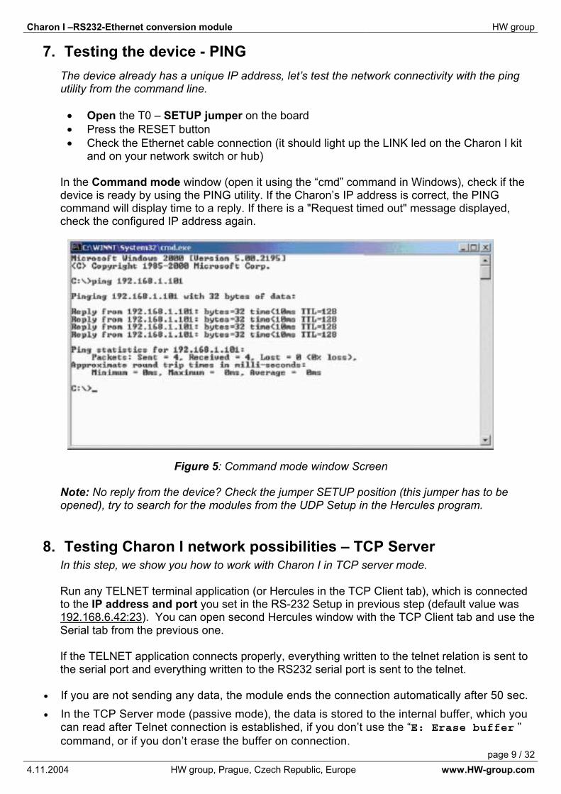
7. Testing the device - PING The device already has a unique IP address, let’s test the network connectivity with the ping utility from the command line.
• Open the T0 – SETUP jumper on the board • Press the RESET button • Check the Ethernet cable connection (it should light up the LINK led on the Charon I kit
and on your network switch or hub)
In the Command mode window (open it using the “cmd” command in Windows), check if the device is ready by using the PING utility. If the Charon’s IP address is correct, the PING command will display time to a reply. If there is a "Request timed out" message displayed, check the configured IP address again.
Figure 5: Command mode window Screen
Note: No reply from the device? Check the jumper SETUP position (this jumper has to be opened), try to search for the modules from the UDP Setup in the Hercules program.
8. Testing Charon I network possibilities – TCP Server In this step, we show you how to work with Charon I in TCP server mode.
Run any TELNET terminal application (or Hercules in the TCP Client tab), which is connected to the IP address and port you set in the RS-232 Setup in previous step (default value was 192.168.6.42:23). You can open second Hercules window with the TCP Client tab and use the Serial tab from the previous one.
If the TELNET application connects properly, everything written to the telnet relation is sent to the serial port and everything written to the RS232 serial port is sent to the telnet.
• If you are not sending any data, the module ends the connection automatically after 50 sec.• In the TCP Server mode (passive mode), the data is stored to the internal buffer, which you
can read after Telnet connection is established, if you don’t use the “E: Erase buffer ” command, or if you don’t erase the buffer on connection.
Charon I –RS232-Ethernet conversion module HW group
page 10 / 324.11.2004 HW group, Prague, Czech Republic, Europe www.HW-group.com
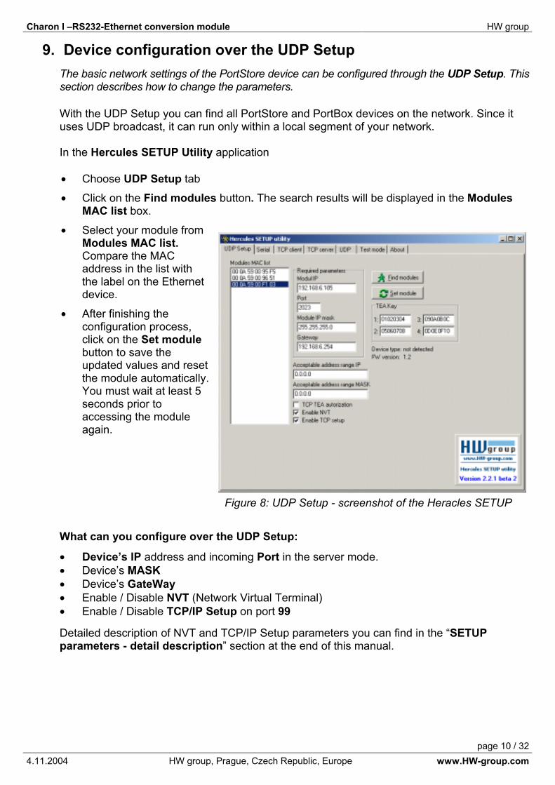
9. Device configuration over the UDP Setup The basic network settings of the PortStore device can be configured through the UDP Setup. This section describes how to change the parameters.
With the UDP Setup you can find all PortStore and PortBox devices on the network. Since it uses UDP broadcast, it can run only within a local segment of your network.
In the Hercules SETUP Utility application
• Choose UDP Setup tab
• Click on the Find modules button. The search results will be displayed in the ModulesMAC list box.
• Select your module from Modules MAC list.Compare the MAC address in the list with the label on the Ethernet device.
• After finishing the configuration process, click on the Set modulebutton to save the updated values and reset the module automatically. You must wait at least 5 seconds prior to accessing the module again.
What can you configure over the UDP Setup:
• Device’s IP address and incoming Port in the server mode. • Device’s MASK• Device’s GateWay• Enable / Disable NVT (Network Virtual Terminal) • Enable / Disable TCP/IP Setup on port 99
Detailed description of NVT and TCP/IP Setup parameters you can find in the “SETUPparameters - detail description” section at the end of this manual.
Figure 8: UDP Setup - screenshot of the Heracles SETUP
Charon I –RS232-Ethernet conversion module HW group
page 11 / 324.11.2004 HW group, Prague, Czech Republic, Europe www.HW-group.com
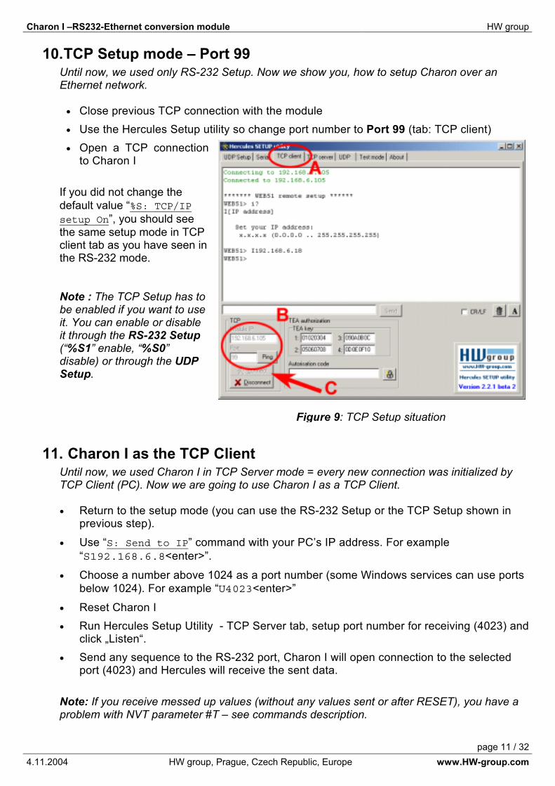
10. TCP Setup mode – Port 99 Until now, we used only RS-232 Setup. Now we show you, how to setup Charon over an Ethernet network.
• Close previous TCP connection with the module • Use the Hercules Setup utility so change port number to Port 99 (tab: TCP client)• Open a TCP connection
to Charon I
If you did not change the default value “%S: TCP/IP setup On”, you should see the same setup mode in TCP client tab as you have seen in the RS-232 mode.
Note : The TCP Setup has to be enabled if you want to use it. You can enable or disable it through the RS-232 Setup(“%S1” enable, “%S0”disable) or through the UDPSetup.
11. Charon I as the TCP Client Until now, we used Charon I in TCP Server mode = every new connection was initialized by TCP Client (PC). Now we are going to use Charon I as a TCP Client.
• Return to the setup mode (you can use the RS-232 Setup or the TCP Setup shown in previous step).
• Use “S: Send to IP” command with your PC’s IP address. For example “S192.168.6.8<enter>”.
• Choose a number above 1024 as a port number (some Windows services can use ports below 1024). For example “U4023<enter>”
• Reset Charon I • Run Hercules Setup Utility - TCP Server tab, setup port number for receiving (4023) and
click „Listen“. • Send any sequence to the RS-232 port, Charon I will open connection to the selected
port (4023) and Hercules will receive the sent data.
Note: If you receive messed up values (without any values sent or after RESET), you have a problem with NVT parameter #T – see commands description.
Figure 9: TCP Setup situation

Charon I –RS232-Ethernet conversion module HW group
page 12 / 324.11.2004 HW group, Prague, Czech Republic, Europe www.HW-group.com
12. NVT – Network Virtual Terminal NVT is a powerful tool which you can use to set and read I/O port’s values, change BaudRate etc. over Ethernet network.
Note: Before using the NVT, please make sure that you have the “V: Network Virtual Terminal On” in SETUP mode. If the NVT is not active, all the NVT commands are ignored and sent to serial port as data! NVT can be enabled in the RS-232 SETUP using the “V1”command.
With NVT enabled, you can control the whole module using almost all standard RFC2217 NVT commands. (Changing the baud rate, setting up the 9th bit through TCP/IP connection and so on). You can also directly control the I/O pins P1.0-P1.7.
With NVT enabled, a new SETUP (RS-232 and TCP/IP) menu appears. There you can set for example the starting value of the I/O port after reset using a “#A” command. (Note: The LED is lit only if there is log 0 on the output pin and LED ENABLE jumper is connected).
• Run the SETUP mode
• Set the “V1” - NVT enable
• Set the “#A254” – default I/O port power-up value. Because of decimal value 254, only one LED, connected to P1.0 will be lit
• RESET the module• Open the Test mode tab in the Hercules• Open the TCP Connection to the module • Write the „FF F6“ to the bottom macro line, check the „HEX“ checkbox and send the
string.In the TeraTerm terminal, you can use the ALT+T (menu “Control” > “Are You There”).
• The Charon module will respond with “<WEB51 HW 6.0 SW 2.4 SN 00954C #01>”.This is a standard device response, which can be controlled via NVT.
Note: Check the detailed NVT description on our website, it’s a very powerful tool and it’s a standard.

Charon I –RS232-Ethernet conversion module HW group
page 13 / 324.11.2004 HW group, Prague, Czech Republic, Europe www.HW-group.com
13. NVT - I/O pins control We extended NVT RFC2217 Standard with some commands to control the binary I/O pins. You can find the detailed description on our website - Download & Support section.
Write the “FF FA 2C 33 AA F0 FF” sequence to the opened raw TCP/IP connection. The P1 port value will be set to the AAh value. The LEDs can be controlled from Test mode tab in the Hercules as shown on the picture.
• If you check the „Write together“ option, the I/O pins command will be sent in byte format (after you click the „Write“ button), if you leave the box unchecked, a bit-command is sent.
• You can use the Received and Sent data windows to view (if enabled) the NVTcommands generated by the buttons.
• The „Read“ button reads the I/O pin’s values and sets the virtual on-screen LEDs to the according state.
• The „Polarity“ and „Inversed“ options change the meaning of checking I/O pins / on screen LEDs to Log 1 or Log 0.

Charon I –RS232-Ethernet conversion module HW group
page 14 / 324.11.2004 HW group, Prague, Czech Republic, Europe www.HW-group.com
14. Sample Codes & Code library We have prepared many examples in different programming languages to make Charon I implementation easier.
Borland C++ Communication Example When implementing your own PC software, you can refer to our easy Borland C++ Builder software Client terminal example. There are easy NVT commands implemented too.
Delphi Communication Example When implementing your own PC software, you can refer to our easy Delphi software Client terminal example. There are easy NVT commands implemented too.
Delphi TCP/IP Server / logger example An example of simple TCP/IP logger written in Borland Delphi 6.0 demonstrates a server that reacts on client requests logs all incoming data, accesses and connection errors in two files. This program also shows how to access Windows registry, native INI files etc.
MS Visual Basic Example Very easy routine for TCP/IP device control over the Winsock from MS Visual Basic 5.0. There are easy NVT commands implemented too for remote control I/O pins.
Java NVT simple Code Example This is a simple example of remote control of the binary I/O pins (over NVT) from the Java application running on the PC or server.
You can test it on IP: 80.250.3.194:4023 - It tests the public IP of the Charon I DK board in our Prague office. The D1 and D6 I/O pins are connected on the board, so if you check the D1 output, wait 3 seconds and read input value, the D6 will be checked because it's connected on the board with D1.
PHP simple Code ExampleThis is a simple example of remote control of the binary I/O pins (over NVT) and serial port (RS-232) from the PHP script, running on the server. It require’s PHP 4.0 and higher..
Try our online demo: http://www.hw-group.com/products/charon1/test/

Charon I –RS232-Ethernet conversion module HW group
page 15 / 324.11.2004 HW group, Prague, Czech Republic, Europe www.HW-group.com
15. Communication security Basic level of security is ensured by defining an IP address range. Alternatively, connections can be authorized using a 128-bit TEA symmetric cipher whenever connection is established.
Defining an IP address range To define an IP address range which is allowed to communicate with the Charon I device, use the commands W, N in the RS-232 Setup or TCP Setup. For more information, look at step 5 or 14.
The TEA encryption & Authorization algorithm A necessary function of TCP/IP devices is secure access and related functions. For simple authorization, you can use the password system (Insert your name & password when prompted before beginning communication). This solution has a big disadvantage because the password is sent in plaintext form over the Ethernet network and it can be read by someone else. It is more desirable to use one of the cryptography methods for secure authorization.
All our devices support TEA authorization for secure access. For more information, read our support manual, how to use & implement TEA (The Tiny Encryption Algorithm).
16. Virtual serial port (VSP) The Virtual serial port driver for Windows is a software tool, which adds a virtual Com port to your Windows OS (COM5 for example) and all the data from this port is re-directed to the other TCP/IP. HW Virtual Serial Port is free TCP/IP Windows virtual serial port.
The HW Virtual Serial Driver is primarily designed for our devices, but you can use it for other devices for free.
The Charon I module opens the connection with a PC and sends the data to the virtual com. The whole situation is just the same as with a normal serial port, but our device can be as far away as you want.
On the Charon I with enabled NVT, you can change the Baud Rate, Parity and other communication properties during the normal communication using the RFC2217 standard, so you have a real remote port.
Note: For using and testing the HW VSP, please read the product’s webpage, you can find all the information you need to setup it with the Charon I modules there.

Charon I –RS232-Ethernet conversion module HW group
page 16 / 324.11.2004 HW group, Prague, Czech Republic, Europe www.HW-group.com
Hardware description Mechanical and electrical parameters, other functions
• Power The module does not include a voltage regulator, therefore the power needs to be +5V with a tolerance of ±10% max. The module consumes approx. 30 – 80 mA. Depending on the Ethernet line load.
• Reset is realized by internal watchdog in the CPU and by voltage resetting circuit in the module.Reset active = the CPU resets on log. 1. The RST pin is bidirectional, which means that it can reset external circuits using software reset from MCU or using a voltage resetting circuit connected on the 3k3 resistor.
• Module programming is done using the PSEN pin. If you hard-connect the PSEN to GND after device reset, the internal processor loader is activated and a program can be uploaded using the Atmel FLIP or our RD2 Flasher software and RS-232 serial line.
Atmel calls this ISP – In System Programming, do not confuse this with ISP for AVR and some x51 processors, where the programming is realized using the SPI synchronized line. In the Atmega128 processor this line is shared on the USART pins.Don’t be confused, for T89C51RD2 programming you only need to hard connect PSEN pin to GND and after device reset you can upload a standard asynchronous RS232 firmware.
• The I/O pins maximum load is defined by the RD2 processor manufacturer as 3,5 mA max for Low level and 0,1 mA max for High level. The Ethernet output load depends on the used separating transformer etc.
• The EMC compatibility of the module depends on the used components. To eliminate interference and noise we suggest connecting the unused I/O pins of the module to 3k3 pull-up resistors. Separating application and TP cable GND’s is fundamental.
Typical errors when GND’s are not separated- You cannot use a switching power supply.. - There is a 1-50% packet loss, but the device seems to work. - There is a problem when connecting a shielded TP cable, instead of unshielded one. This creates a GND loop which can destroy the whole device.
• CHARON I module schematic can be downloaded as PDF document on our website www.HWgroup.cz (on the Charon I module page). You can also download development kits schematics.
• RS-485 interface can be connected using this schematic.The CTS and RTS Charon pins are used as direct TTL outputs for the RS-485 line driver.
The HW Echo enablesyou to receive from the RS485 line real transmitted data.

Charon I –RS232-Ethernet conversion module HW group
page 17 / 324.11.2004 HW group, Prague, Czech Republic, Europe www.HW-group.com
Firmware upload to the Charon I module The Charon Module already has the default Ethernet / RS-232 Converter firmware uploaded. If you want to update it, or upload another FW, you can program on module MCU’s using the original Atmel Flip program. You should download FLIP from the official web pages of the Atmel company - search for the FLIP (FLexible In-system Programmer) utility. An older, but stable version of Atmel FLIP 1.8, you can find on our CD or website.
ISP module programming Connect the device to the RS-232 serial link (using the serial cable, which is included in the delivery) and connect the PSEN jumper. In the PortStore or PortBox devices the jumper is inside the box (you have to open it), It the occurance that the jumper plug isn't mounted, short the pins using a metal paperclip. Check the MPU type (it's the smaller chip with the Atmel logo), for whether it is the "AT89C51RD2" or "AT89C51RE2".
• Short the PSEN jumper • Switch on the power supply• Run the FLIP software, select the processor type
(Device => Select => T89C51RD2 / RE2)• Open the serial port, you have connected to the
Charon I module.• If there was an error displayed, check the PSEN
jumper position, or check the serial cable type (3 wire, RxD, TxD, GND).
• Open the firmware .HEX file. • Do not forget to check the ERASE and BLANK CHECK checkboxes.• Program the FLASH memory• Disconnect the Atmel Flip program from the COM port after programming has done.• Switch off the power for the device• Open the PSEN jumper, short the SETUP (T0) jumper• Open RS-232 serial terminal on 9600 8N1 and switch on the Charon I module.• Set “D0” or other command to load default parameters.
Now the FirmWare is updated, you can setup the Charon firmware..
Troubleshooting• Be careful for used cables. If you are using a prolong cable and gender-changer it isn't a
LapLink cable..• Don't forget to D0 Default reset• You can't change MAC addresses as its hardwired in the hardware.• This procedure can be used for update only, it doesn't function with new devices because of
firmware protections.

Charon I –RS232-Ethernet conversion module HW group
page 18 / 324.11.2004 HW group, Prague, Czech Republic, Europe www.HW-group.com
Connecting the module to an Ethernet network We recommend connecting the Ethernet outputs according to the following picture. We use two different separating transformers:
• YCL20F001N – standard separating transformer.• LF1S022 – RJ45 built-in separating transformer.
Both schematics can be found at the end of this datasheet in the typical wiring scheme. For CharonI version 6.20 a 100R resistor between TPI+ a TPI- pins was used, higher versions have this resistor built in the module itself.
When designing an application PCB, be sure to separate device GND from Ethernet GND! If you connect them, you may experience strange behavior.
Recommended wiring with YCL20F001N or FB2022:
This circuit is better for industrial applications, because it has a higher insulation, thanks to using a standard separating transformer.
LF1S022 - RJ45 connector with built-in separating transformer

Charon I –RS232-Ethernet conversion module HW group
page 19 / 324.11.2004 HW group, Prague, Czech Republic, Europe www.HW-group.com
Typical application scheme
Charon I –RS232-Ethernet conversion module HW group
page 20 / 324.11.2004 HW group, Prague, Czech Republic, Europe www.HW-group.com
Charon I – peripheral extending directionsCharon I module can be extended using shift registers and other peripherals. You can have many modifications supported by certain firmware versions. Here you will find a short description of such modifications.
Available peripherals Most of the described schemes are based on the Charon I&II Development Board schematic version 5.0 and higher (Charon DB 5). Some older versions use other wirings, but we will follow this for Charon I.
• 1 Wire –DS1822, DS1820 thermometers and other peripherals. [B, C, D, E]• Shift registry OUTPUT – cascaded output shift registers. [A, B, C, D, E]• Shift registry INPUT – cascaded input shift registers. [A, B, C, D, E]• A/D converter – extended peripheral with a shift register-like interface. It connects instead of
LCD display. [C]• LCD display over SHIFT register – intelligent LCD display connected as an independent
peripheral using 4 bits and shift register. [B, D, E]
Shortcuts for firmware version, which supports this peripheral:: [A] Classic Converter, version 3.x and higher [B] Web51 Home web Control version 2.x and higher [C] SNMP I/O Thermometer [D] Charon II testing utility [E] Charon I&II DB peripheral
Recommended port P1 pin assignment
Ch I / I/O Recommended assignment
P1.0 I/O1 Wire bus Reserved for connecting thermometers and other peripherals. Must be protected using transil when prolonging out of the device. Max. length is approx. 2 meters !
P1.1 OUTSHIFT_LCD_SET or SHIFT_CS_SETConfirms writing in LCD’s or A/D Converter’s shift register. The shift register transfers the data from 74595 to the parallel output.
P1.2 INSHIFT_IN_LOADConfirms writing in the input’s shift register. Log. 0 = transfer to inner register. Also a second serial channel input (for Charon II), resistor separated.
P1.3 OUT Second serial line output (not used in Charon I).
P1.4 IN SHIFT_IN or AD DO Input for data from the parallel inputs shift register (74165)1.
P1.5 OUTSHIFT_LED_SETConfirms writing in the binary inputs shift. The shift register transfers the data from 74595 to the parallel output.
P1.6 OUT SHIFT_OUT a AD DI Shift registers and AD converter data output.
P1.7 OUT SHIFT_CLKClock signal for shift registers.
Charon I –RS232-Ethernet conversion module HW group
page 21 / 324.11.2004 HW group, Prague, Czech Republic, Europe www.HW-group.com
Device functions listing Basic network functions I: Address Assign IP address J: Port Assign incoming IP port M: Mask Define local network mask G: Gateway Define local network GateWay
IP Address access restrictions W: Address Define IP address value to enable device's access N: Mask Define IP address mask to enable device's access
Client or Client/Server mode settings S: Send to IP Define opposite IP address when device opening TCP connection as the TCP
Client.U: Port Define opposite IP incoming port
IP communication settingsT: IP mode TCP / UDP mode V: Network Virtual Terminal On / Off - NVT support (RFC854, NVT description)K: Keep connection On / Off - When On and NVT=On sending every 8 seconds NVT NOP command to
the TCP connection = timeout prolonging E: Erase buffer on Erase serial port incoming buffer when: NONE / Close TCP/IP connection / Open
TCP/IP connection / Open & Close TCP/IP connection
Serial port parameters&B: Speed Serial port baudrate 300 .. 115.200 Bd - step 50 Bd &D: Data bits 7 / 8 bits in one serial port frame &P: Parity None / Odd / Even / Mark / Space &V: Variable parity On / Off - 9. bit synchronous transmition support &S: Stop bits 1 / 2 &C: Flow Control NONE / RTS/CTS / Xon/Xoff&R: RS485/RS422 control RTS = High [+8V] / RTS = Low [-8V]
TxRTS HW echo ON / TxRTS HW echo OFF - for RS-485 mode &T: Serial Line Timeout 0 = Auto / 1..254 chars
Define max. intercharacter gap for Serial -> TCP/IP packetizer
&G: Char. Transmit Delay 0 = none / 1..254 ms - Insert intercharacter delay to the TCP/IP -> Serial (serial port outgoing data stream).
&H: Tx Control FULL duplex / HALF duplex - (recommended for the RS-485) &M: Serial buffer size Medium Rx / Medium Tx = (50% / 50% of infernal buffer size)
Low Rx / High Tx = (30% / 70% of infernal buffer size) High Rx / Low Tx = (70% / 30% of infernal buffer size)
&O: Buffer SpaceCompresion Off / On / Transparent (internal compress space characters only)
Security parameters%A: TCP authorization On / Off - it's with every opening TCP connection %K: TEA key Set 16 bytes of the TEA key ( key = TEA "password" ) %S: TCP/IP setup Off / On - it's remote TCP/IP Setup on the TCP port 99
Charon I –RS232-Ethernet conversion module HW group
page 22 / 324.11.2004 HW group, Prague, Czech Republic, Europe www.HW-group.com
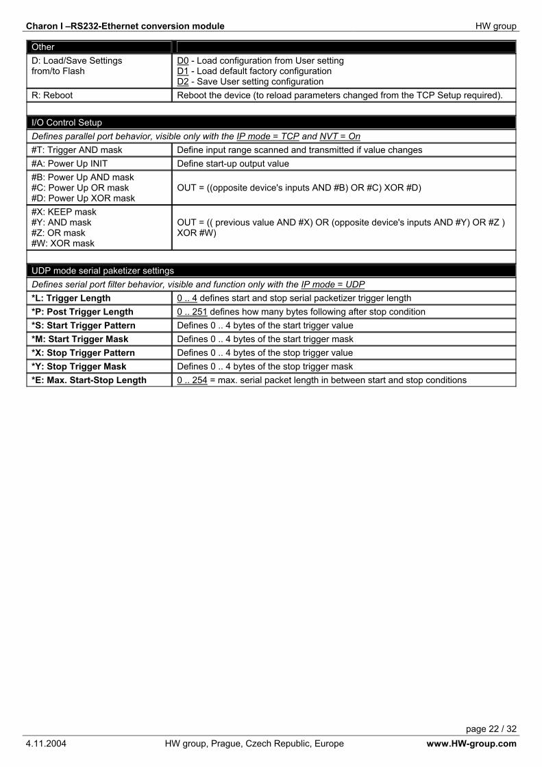
OtherD: Load/Save Settingsfrom/to Flash
D0 - Load configuration from User setting D1 - Load default factory configurationD2 - Save User setting configuration
R: Reboot Reboot the device (to reload parameters changed from the TCP Setup required).
I/O Control SetupDefines parallel port behavior, visible only with the IP mode = TCP and NVT = On #T: Trigger AND mask Define input range scanned and transmitted if value changes #A: Power Up INIT Define start-up output value #B: Power Up AND mask #C: Power Up OR mask #D: Power Up XOR mask
OUT = ((opposite device's inputs AND #B) OR #C) XOR #D)
#X: KEEP mask #Y: AND mask #Z: OR mask #W: XOR mask
OUT = (( previous value AND #X) OR (opposite device's inputs AND #Y) OR #Z ) XOR #W)
UDP mode serial paketizer settings Defines serial port filter behavior, visible and function only with the IP mode = UDP*L: Trigger Length 0 .. 4 defines start and stop serial packetizer trigger length *P: Post Trigger Length 0 .. 251 defines how many bytes following after stop condition *S: Start Trigger Pattern Defines 0 .. 4 bytes of the start trigger value *M: Start Trigger Mask Defines 0 .. 4 bytes of the start trigger mask *X: Stop Trigger Pattern Defines 0 .. 4 bytes of the stop trigger value *Y: Stop Trigger Mask Defines 0 .. 4 bytes of the stop trigger mask *E: Max. Start-Stop Length 0 .. 254 = max. serial packet length in between start and stop conditions

Charon I –RS232-Ethernet conversion module HW group
page 23 / 324.11.2004 HW group, Prague, Czech Republic, Europe www.HW-group.com
SetupHere you can find all the „RS-232 Setup“ and „TCP Setup“ parameters. The parameters are described in the following pattern:
MAC Address [00:0A:59:00:95:6C]MAC address is a unique network device address on the Ethernet and is always factory-preset. You can find it on the label inside the device. Using this address, the devices can be distinguished for example in the UDP mode of the configuration program. The address remains after restoring of the default configuration with the "D0" command.
I: Address [192.168.6.15]Configuration of the PortBox's IP address.
J: Port [23]Configuration of the PortBox's communication port – range: 1 .. 19.999.Port 99 is used for TCP configuration, if supported by the version and enabled in the setup.
M: Mask [255.255.255.0]Configuration of the IP mask for the local network. All IP addresses outside of the area delimited by the PortBox's own IP address and this mask will be accessed via the Gateway.
G: Gateway [192.168.6.254]Address of the gateway that provides access to outside networks, as defined by the IP address and the mask.
====== In IP Setup ======
W: Address [0.0.0.0]IP address of a network or computer that is allowed to communicate with the PortBox. This value must result from multiplying the remote IP address and the restriction mask (option N), otherwise the PortBox does not react.
Consequence of the MASK, IP and GW
Ethernet device communicates:
• You don’t even need Gateway in localEthernet but IP addresses of both sides must be chosen from allowed mask.
Therefore there might be difference on the last byte only from IP address when configuration of mask is 255.255.255.0
• Out of local net - use Gateway, that is located in MASK allowed range of IP addresses.
Besides basic configuration it is possible to restrict the range of IP addresses that the converter will not communicate with in „In IP Setup“. We recommend to keep this parameter on the value 0.0.0.0.
X: Parameter name [default value]
Y: Parameter (description)Description…

Charon I –RS232-Ethernet conversion module HW group
page 24 / 324.11.2004 HW group, Prague, Czech Republic, Europe www.HW-group.com
N: Mask [0.0.0.0]This mask restricts addresses that may communicate with the PortBox. Security can be greatly enhanced by setting a fixed address or a suitable restrictive mask that disallow communication with unauthorized parties.
====== Out IP Setup ======
S: Send to IP [192.168.0.252]Defines the IP address which the PortBox communicate with (useful on large networks).
U: Port [23]Remote IP address and port for establishing a connection upon data reception from the serial port. Value 0.0.0.0 switches the PortBox into passive mode. Note: If UDP communication is used, a remote address must be specified here. The PortBox does not establish connections, responses are sent to this address only!
T: IP mode [TCP]
0: TCP (TCP/IP Mode, NVT available)1: UDP (UDP/IP Mode, NVT not available)
Switches between the TCP and UDP protocols. UDP is faster but packets can be lost or delivered out of order. Hence it is suitable for communication only on a local network segment in request-reply mode, usually for converting a RS-485 communication.UDP communication is hard to debug since there is no simple PC terminal (like TELNET for TCP/IP). TCP has a predefined time of inactivity, after which the connection is closed. If you want to keep the connection open, see the “keep connection” command.
V: Network Virtual Terminal [Off]
0: Off (don't use telnet control code, pass through to serial port)1: On (accept telnet control code)
Network Virtual Terminal allows the interpreting of Telnet protocol sequences including certain RFC2217 extensions, enabling on-the-fly changes of serial port parameters (speed, parity, ...).NVT description is available in the "Programming Ethernet Applications" guide at our website. When communicating with the serial port using telnet, e.g. with the TeraTerm program, this option should be turned on. Otherwise, telnet control commands (seen as "junk") intended for configuration negotiation at the beginning of the communication are forwarded to the serial port. If you don't want to use this option, set your client to RAW communication mode.
K: Keep connection [Off]
0: no keep connection (preferred)1: keep connection
This option allows keeping the connection alive with NOP commands, as long as NVT is on.

Charon I –RS232-Ethernet conversion module HW group
page 25 / 324.11.2004 HW group, Prague, Czech Republic, Europe www.HW-group.com
E: Erase buffer on [Open connection] 0: none 1: close TCP/IP connection 2: open TCP/IP connection 3: open & close TCP/IP connection
Option to clear the internal PortBox buffer whenever a connection is established or closed. This option is useful e.g. if your device periodically says "I'm alive" and you don't want to waste time retrieving these notifications from the buffer.
====== Serial Setup ======
&B: Speed [9600]Configuration of the communication speed for the serial line, range 50..115.200 Bd. To set9600 Bd, enter : „&B9600“.
&D: Data bits [8]7: 7 bits 8: 8 bits (issue „&D8“)
Number of data bits for the serial transfer.
&P: Parity [None]N: none O: odd E: evenM: mark S: space
Parity of the serial asynchronous communication
&V: Variable parity [0]0: disabled 1: enabled
Variable parity is useful if you need a full 9-bit communication, prolonged over the Ethernet network between 2 PortBox devices. Otherwise leave the Variable parity disabled.
&S: Stop bits [2]Number of stop bits for the RS232 serial line. It is possible to set 1 or 2 bits.
Charon I –RS232-Ethernet conversion module HW group
page 26 / 324.11.2004 HW group, Prague, Czech Republic, Europe www.HW-group.com
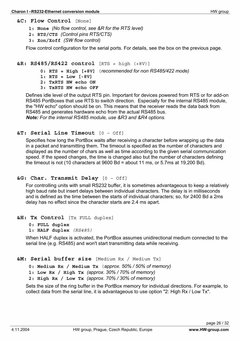
&C: Flow Control [None]
1: None (No flow control, see &R for the RTS level)2: RTS/CTS (Control pins RTS/CTS)3: Xon/Xoff (SW flow control)
Flow control configuration for the serial ports. For details, see the box on the previous page.
&R: RS485/RS422 control [RTS = high (+8V)]
0: RTS = High [+8V] (recommended for non RS485/422 mode) 1: RTS = Low [-8V] 2: TxRTS HW echo ON 3: TxRTS HW echo OFF
Defines idle level of the output RTS pin. Important for devices powered from RTS or for add-on RS485 PortBoxes that use RTS to switch direction. Especially for the internal RS485 module, the "HW echo" option should be on. This means that the receiver reads the data back from RS485 and generates hardware echo from the actual RS485 bus.Note: For the internal RS485 module, use &R3 and &R4 options.
&T: Serial Line Timeout [0 – Off]Specifies how long the PortBox waits after receiving a character before wrapping up the data in a packet and transmitting them. The timeout is specified as the number of characters and displayed as the number of chars as well as time according to the given serial communication speed. If the speed changes, the time is changed also but the number of characters defining the timeout is not (10 characters at 9600 Bd = about 11 ms, or 5.7ms at 19,200 Bd).
&G: Char. Transmit Delay [0 – Off]For controlling units with small RS232 buffer, it is sometimes advantageous to keep a relatively high baud rate but insert delays between individual characters. The delay is in milliseconds and is defined as the time between the starts of individual characters; so, for 2400 Bd a 2ms delay has no effect since the character starts are 2.4 ms apart.
&H: Tx Control [Tx FULL duplex] 0: FULL duplex 1: HALF duplex (RS485)
When HALF duplex is activated, the PortBox assumes unidirectional medium connected to the serial line (e.g. RS485) and won't start transmitting data while receiving.
&M: Serial buffer size [Medium Rx / Medium Tx]
0: Medium Rx / Medium Tx (approx. 50% / 50% of memory)1: Low Rx / High Tx (approx. 30% / 70% of memory)2: High Rx / Low Tx (approx. 70% / 30% of memory)
Sets the size of the ring buffer in the PortBox memory for individual directions. For example, to collect data from the serial line, it is advantageous to use option "2: High Rx / Low Tx".
Charon I –RS232-Ethernet conversion module HW group
page 27 / 324.11.2004 HW group, Prague, Czech Republic, Europe www.HW-group.com
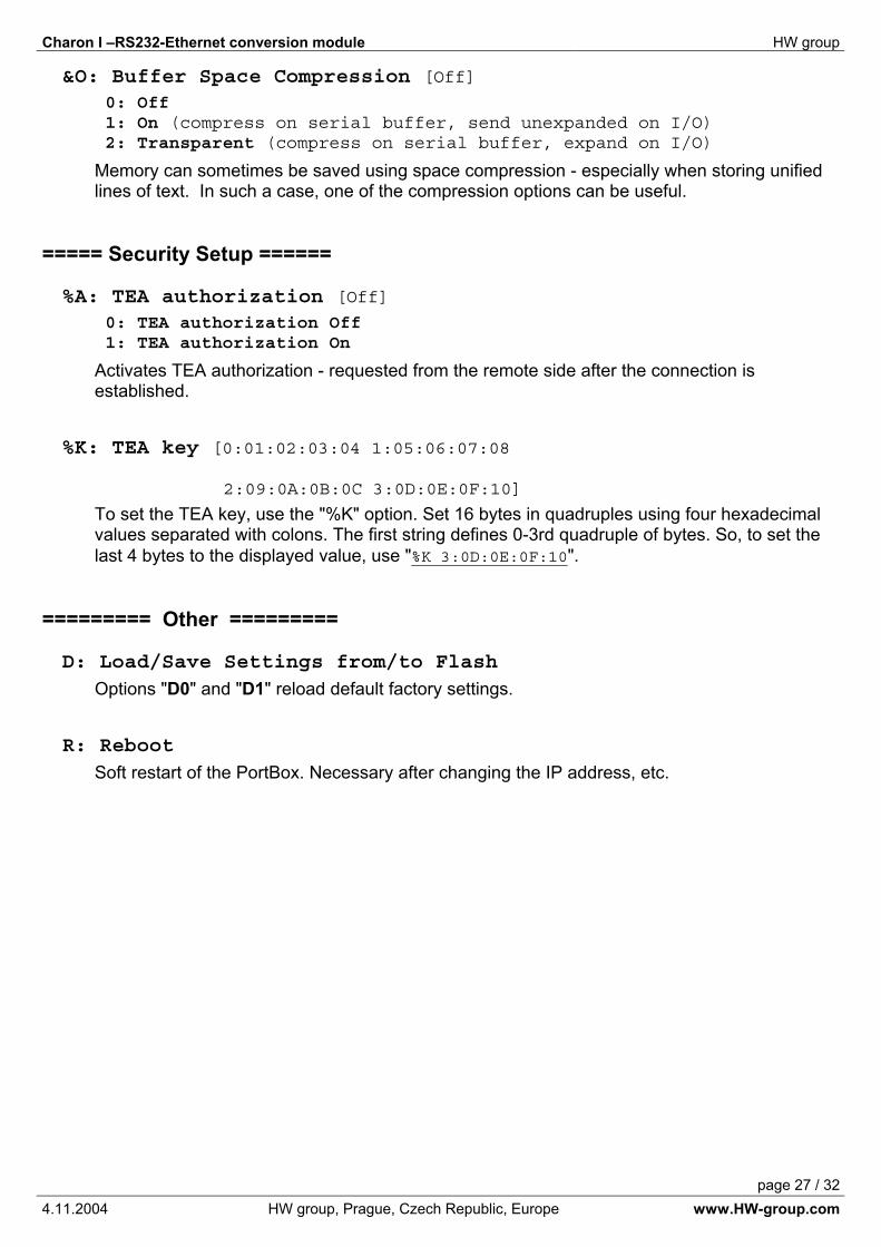
&O: Buffer Space Compression [Off]0: Off 1: On (compress on serial buffer, send unexpanded on I/O)2: Transparent (compress on serial buffer, expand on I/O)
Memory can sometimes be saved using space compression - especially when storing unified lines of text. In such a case, one of the compression options can be useful.
===== Security Setup ======
%A: TEA authorization [Off]0: TEA authorization Off 1: TEA authorization On
Activates TEA authorization - requested from the remote side after the connection is established.
%K: TEA key [0:01:02:03:04 1:05:06:07:08
2:09:0A:0B:0C 3:0D:0E:0F:10]
To set the TEA key, use the "%K" option. Set 16 bytes in quadruples using four hexadecimal values separated with colons. The first string defines 0-3rd quadruple of bytes. So, to set the last 4 bytes to the displayed value, use "%K 3:0D:0E:0F:10".
========= Other =========
D: Load/Save Settings from/to Flash Options "D0" and "D1" reload default factory settings.
R: Reboot Soft restart of the PortBox. Necessary after changing the IP address, etc.
Charon I –RS232-Ethernet conversion module HW group
page 28 / 324.11.2004 HW group, Prague, Czech Republic, Europe www.HW-group.com
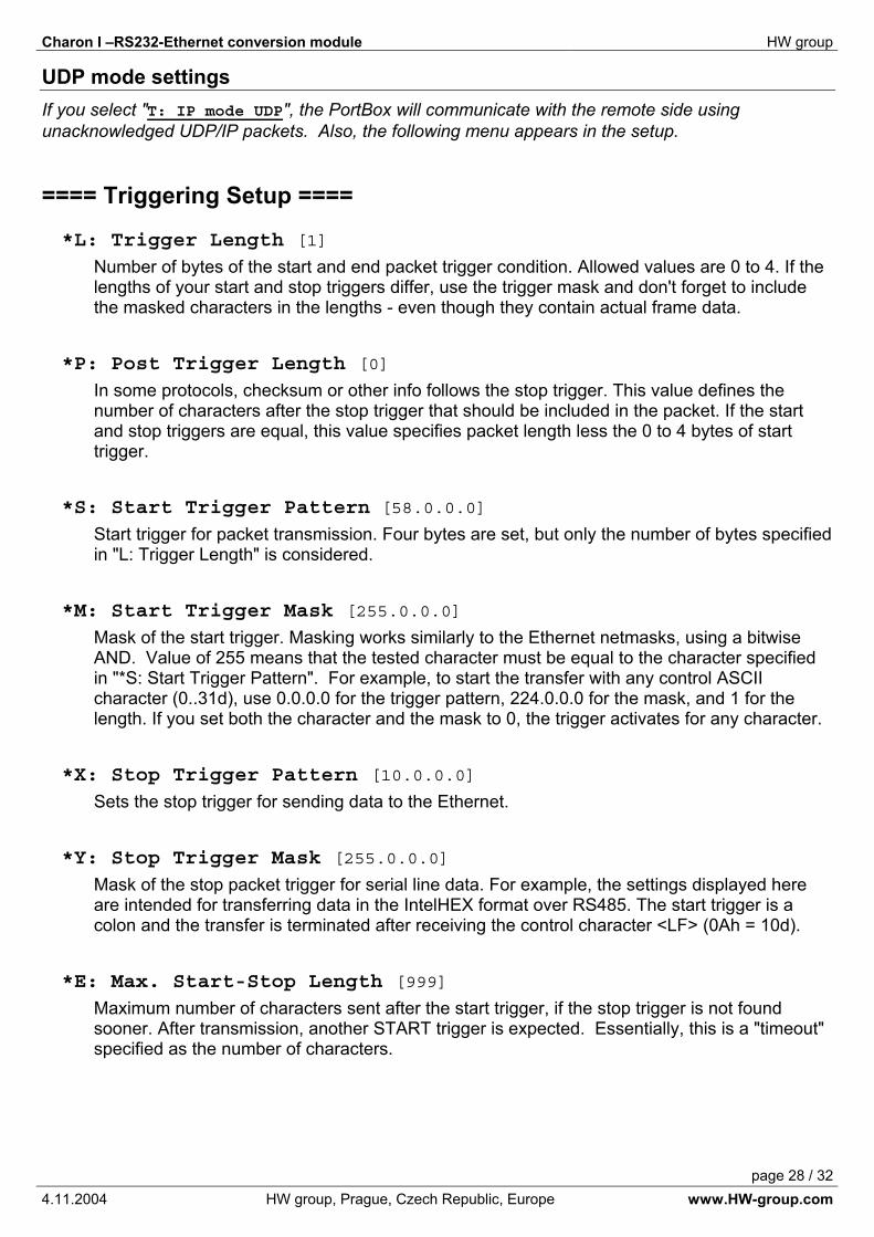
UDP mode settings If you select "T: IP mode UDP", the PortBox will communicate with the remote side using unacknowledged UDP/IP packets. Also, the following menu appears in the setup.
==== Triggering Setup ====
*L: Trigger Length [1]Number of bytes of the start and end packet trigger condition. Allowed values are 0 to 4. If the lengths of your start and stop triggers differ, use the trigger mask and don't forget to include the masked characters in the lengths - even though they contain actual frame data.
*P: Post Trigger Length [0]In some protocols, checksum or other info follows the stop trigger. This value defines the number of characters after the stop trigger that should be included in the packet. If the start and stop triggers are equal, this value specifies packet length less the 0 to 4 bytes of start trigger.
*S: Start Trigger Pattern [58.0.0.0]Start trigger for packet transmission. Four bytes are set, but only the number of bytes specified in "L: Trigger Length" is considered.
*M: Start Trigger Mask [255.0.0.0]Mask of the start trigger. Masking works similarly to the Ethernet netmasks, using a bitwise AND. Value of 255 means that the tested character must be equal to the character specified in "*S: Start Trigger Pattern". For example, to start the transfer with any control ASCII character (0..31d), use 0.0.0.0 for the trigger pattern, 224.0.0.0 for the mask, and 1 for the length. If you set both the character and the mask to 0, the trigger activates for any character.
*X: Stop Trigger Pattern [10.0.0.0]Sets the stop trigger for sending data to the Ethernet.
*Y: Stop Trigger Mask [255.0.0.0]Mask of the stop packet trigger for serial line data. For example, the settings displayed here are intended for transferring data in the IntelHEX format over RS485. The start trigger is a colon and the transfer is terminated after receiving the control character <LF> (0Ah = 10d).
*E: Max. Start-Stop Length [999]Maximum number of characters sent after the start trigger, if the stop trigger is not found sooner. After transmission, another START trigger is expected. Essentially, this is a "timeout" specified as the number of characters.

Charon I –RS232-Ethernet conversion module HW group
page 29 / 324.11.2004 HW group, Prague, Czech Republic, Europe www.HW-group.com
I/O Controller mode settings With enable Network Virtual Terminal “V: Network Virtual Terminal [Off]”, there is one more menu displayed on the bottom of the commands listing. It’s the parameters for the I/O Controller functions. With these parameters you can define I/O port using.
#A: Power Up INIT [102]Specifies the start up value, which is stored into the I/O pins after each reset. This value is stored before the module tries to connect to the other side.
#T: Trigger AND mask [240]Defines the logical 1 and the input width. This predefined input will be transferred and synchronized with the other side via TCP/IP. If you set the “0x00” value, the I/O controller does nothing on the input change. If you set the “0xF0“ = 240 decimal value, the I/O Controller responds on the D7,D6,D5,D4 input pins.In case the Controller is in the “Active mode” (Client/Server mode), the reaction on the input pins is precisely the same as in the Serial link data receive case. If the connection is established, the NVT command is sent to the other side to change its I/O pins value.If the Controller is in the “Passive mode” (Server only) and the connection is closed, there will be no packets or NVT command sends. The information about changed inputs is sent only if there was a connection with a Client established.
Note: Even though there is no information about changed input pins transferred; it is possible to read the I/O pins state using standard NVT commands.
Note: The input pins are scanned every 1ms. The data value is changed, only if this value stays on the input pins at least 2 machine cycles (1,2 – 2,0ms).
Data synchronization (with opposite device) after RESET The communication parts of the program are initialized after the #A: Power Up INIT value is stored into the output pins. After that the Controller will try to establish the TCP/IP connection with the other side and tries to read the input data using the following function:
The unit tries to connect the other side during the first 50 seconds after power up. If the connection is not established in 50 seconds, the #A: Power Up INIT value will remain on the I/O pins.
#B: Power Up AND mask [255]The other side’s values width, which should make changes after receiving the NVT command.
#C: Power Up OR mask [0]
Specifies the I/O pins, which might be changed after the RESET is preceded. If you are using some pins as inputs, you can specify these input pins in this value so the input pins cannot be used as output pins.
#D: Power Up XOR mask [0]XOR is useful function if you want to invert polarity of some pins. XOR value specifies the output pins, which will be inverted to the power up received value.
OUTPUT = (The data read from the other side AND #B) OR #C

Charon I –RS232-Ethernet conversion module HW group
page 30 / 324.11.2004 HW group, Prague, Czech Republic, Europe www.HW-group.com
The data synchronization During standard communication with opposite device, the following commands are used to define I/O port functions.
#X: KEEP mask [0]This value defines the output pins, which might be changed by the other side and by the standard NVT access as well.
#Y: AND mask [255]
Defines the bits, which are transferred from the other side. For instance 0x00 means that the output should not be changed by the other side. In the other way, the #X=0xFF means, that all the pins can be changed using the NVT command.
#W: XOR mask [0]XOR is a useful function if you want to invert polarity of some pins. XOR value specifies the output pins, which will be inverted to the received value.
#Z: OR mask [0]Specifies the Output pins, which might be changed under opposite side inputs. If you are using some pins as inputs (direct output from Charon I for example), you can specify these input pins in this value so the input pins cannot be used as output pins.
ExamplesYou can set each input or output bit itself. See the following examples for a better understanding:
• Transfer full 2x 8. bit (8x input to the 8x output and vice versa): Power Up: T=255; B=255; C=0; D=0; X=255; Y=255; W=0; Z=0;
• No data transfer, NVT access to the I/O pins only: B=0; X=255; Y=0; W=0; Z=0;
• Hold output on log. 0: OUTPUT = (X.n =0 Y.n =0 Z.n =0)
• Hold output on log. 1: OUTPUT = (Z.n =1)
• Transfer Binary Inputs only, Outputs accessible over NVT only: Power Up: T=255; B=0; C=0; D=0; X=255; Y=0; W=0; Z=0;
• Accept Binary Output changes only, Inputs accessible over NVT only: Power Up: T=0; B=255; C=0; D=0; X=255; Y=255; W=0; Z=0;
• Charon I – D0-D3 Inputs, D4-D7 Outputs: Power Up: T=15; B=240; C=0; D=0; X=255; Y=240; W=0; Z=15;
(Note: Charon I bi-directional pins are used as inputs, only if there is written log. 1 to the output register => Z=15)
OUTPUT = (Output’s value before AND #X) OR (Data received from other side AND #Y) OR #Z
Charon I –RS232-Ethernet conversion module HW group
page 31 / 324.11.2004 HW group, Prague, Czech Republic, Europe www.HW-group.com
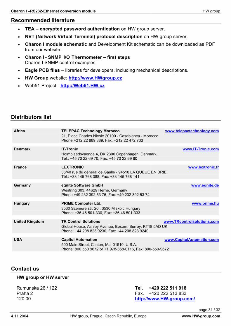
Recommended literature• TEA – encrypted password authentication on HW group server. • NVT (Network Virtual Terminal) protocol description on HW group server. • Charon I module schematic and Development Kit schematic can be downloaded as PDF
from our website. • Charon I - SNMP I/O Thermometer – first steps
Charon I SNMP control examples.• Eagle PCB files – libraries for developers, including mechanical descriptions.• HW Group website: http://www.HWgroup.cz• Web51 Project - http://Web51.HW.cz
Distributors list
Africa TELEPAC Technology Morocco www.telepactechnology.com21, Place Charles Nicole 20100 - Casablanca - MoroccoPhone +212 22 889 889, Fax. +212 22 472 733
Denmark IT-Tronic www.IT-Tronic.comHolmblaedsvaenge 4, DK 2300 Copenhagen, Denmark. Tel.: +45 70 22 69 70, Fax: +45 70 22 69 80
France LEXTRONIC www.lextronic.fr36/40 rue du général de Gaulle - 94510 LA QUEUE EN BRIE Tél.: +33 145 768 388, Fax: +33 145 768 141
Germany egnite Software GmbH www.egnite.deWestring 303, 44629 Herne, Germany Phone +49 232 392 53 75, Fax. +49 232 392 53 74
Hungary PRIME Computer Ltd. www.prime.hu3530 Szemere str. 20., 3530 Miskolc Hungary Phone: +36 46 501-330, Fax: +36 46 501-333
United Kingdom TR Control Solutions www.TRcontrolsolutions.comGlobal House, Ashley Avenue, Epsom, Surrey, KT18 5AD UKPhone: +44 208 823 9230, Fax: +44 208 823 9240
USA Capitol Automation www.CapitolAutomation.com500 Main Street, Clinton, Ma. 01510, U.S.A. Phone: 800 550 9672 or +1 978-368-0116, Fax: 800-550-9672
Contact us HW group or HW server
Rumunska 26 / 122 Tel. +420 222 511 918Praha 2 Fax. +420 222 513 833 120 00 http://www.HW-group.com/