Embed Size (px)
Citation preview

Embedded Linux on Xilinx
MicroBlaze
Lab Manual
V11.3
XUPV5 Development
Board
PetaLogix / XUP Professors’ WorkshopEmbedded Linux for the Xilinx MicroBlaze Soft Processor lab1.1
Lab 1.1 – A First Look
RationaleEmbedded Linux is the use of a Linux operation system in embedded systems. Unlike desktop and server versions of Linux, embedded versions of Linux are designed for devices with relatively limited resources. MicroBlaze is a soft processor core designed for Xilinx FPGAs; it supports Embedded Linux. In most labs of this XUP workshop, we will run Embedded Linux on MicroBlaze.
Objectives● Learn how to power-on the development board used in the workshop● Learn how to login to the MicroBlaze Linux system● Make comparisons between the embedded Linux and desktop Linux environments
IntroductionThis first lab session is a basic introduction to embedded Linux, and the development boards that we are using for the workshop. The basic activities covered here will be used repeatedly through the later Lab sessions, so please be sure to ask if you have any questions or concerns.
TimeThis lab session will run for approximately 15 minutes.
Typographic ConventionsCommands and directory names are typeset in a non-proportional font. Commands to be executed on the development (desktop) workstation are like this:
[host]$ command and parameters
while commands to be executed on the MicroBlaze Linux target look like this:
# run my Linux application
© 2009 PetaLogix Qld Pty Ltd. 1 of 6
PetaLogix / XUP Professors’ WorkshopEmbedded Linux for the Xilinx MicroBlaze Soft Processor lab1.1
Before You Start● Ensure the power switch is in 'off' position.● Ensure the JTAG cable is connecting the development board to the PC.● Ensure the serial cable is connecting the development board to the PC.● Ensure power cable for the development board is connected.● Ensure the Ethernet port on the development board is connected to the 10/100 Ethernet.
Initializing the Workshop EnvironmentBy default, your CentOS image has already setup the workshop environment for you. If you want to set up the working environment manually in future, please refer to the section “Workshop preparation” in the Appendix at the end of this lab1.1 manual.
Powering up the Board and logging inPut the power switch to “on” position to apply power to the MicroBlaze Linux system.
Watch the kermit terminal as it goes through the Linux boot process. Messages similar to the following should be seen on the kermit console:
0x00000000-0x00168000 : "ROMfs" uclinux[mtd]: set ROMfs to be root filesystem index=6 TCP cubic registered NET: Registered protocol family 1 NET: Registered protocol family 17 VFS: Mounted root (cramfs filesystem) readonly. Freeing unused kernel memory: 88k freed Mounting proc: Mounting var: Populating /var: Running local start scripts. Mounting /etc/config: Populating /etc/config: flatfsd: Created 6 configuration files (192 bytes) Mounting sysfs: Setting hostname: Setting up interface lo: Setting up interface eth0: Starting portmap: Starting httpd:
uclinux login:
When prompted, login as “root”, using password “root” (no quotes)
© 2009 PetaLogix Qld Pty Ltd. 2 of 6
PetaLogix / XUP Professors’ WorkshopEmbedded Linux for the Xilinx MicroBlaze Soft Processor lab1.1
ExploringIt is interesting to scroll the terminal up and review the bootup log – existing Linux users will recognize much of the output (as they should, it’s the same operating system!)
Spend the next 15 minutes exploring! Most of the usual Linux commands are available:
ls, vi, cat, gpio-test&
Executing:
# ls /bin
will list the applications currently installed.
Executing `gpio-test` will test the GPIOs which are DIP switches, LEDs and push buttons:● e.g. # gpio-test -d /dev/gpio1 -o 0x1
This command will output '0x1' to GPIO LEDs. Watch the status change on the 8 GPIO LEDs on the board.
● e.g. Put any one of the DIP switches to “on” position and type: # gpio-test -d /dev/gpio0 -i
The input from the DIP switches will be shown on the kermit window.
Another interesting place to explore is the /proc directory. This is a virtual directory that provides a window into the kernel. For example, the file /proc/cpuinfo contains details about the CPU. /proc/interrupts gives interrupt statistics, and so on.E.g.
# cat /proc/cpuinfo CPU-Family: MicroBlaze FPGA-Arch: spartan3e CPU-Ver: 7.20.c CPU-MHz: 50.00 BogoMips: 24.72 HW-Div: no HW-Shift: yes Icache: 2kB Dcache: 2kB HW-Debug: yes # cat /proc/interrupts CPU0 0: 7285 level OPB-INTC timer 1: 7 edge OPB-INTC eth0 2: 212 edge OPB-INTC uartlite #
The contents of /proc/cpuinfo and /proc/interrupts shown as the above are just an
© 2009 PetaLogix Qld Pty Ltd. 3 of 6
PetaLogix / XUP Professors’ WorkshopEmbedded Linux for the Xilinx MicroBlaze Soft Processor lab1.1
example. Your results could be different from it. The details in /proc/cpuinfo depends on the underlined FPGA system while the details in /proc/interrups depends on the number of interrupts that have happened in the system.
/tmp is a writable temporary file system, you can create and edit files there.
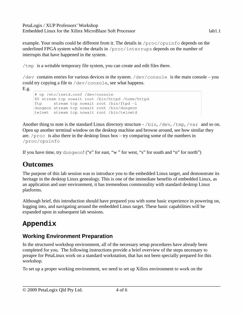
/dev contains entries for various devices in the system. /dev/console is the main console – you could try copying a file to /dev/console, see what happens.E.g.
# cp /etc/inetd.conf /dev/console 80 stream tcp nowait root /bin/httpd /home/httpd ftp stream tcp nowait root /bin/ftpd -l dungeon stream tcp nowait root /bin/dungeon telnet stream tcp nowait root /bin/telnetd
Another thing to note is the standard Linux directory structure - /bin, /dev, /tmp, /var and so on. Open up another terminal window on the desktop machine and browse around, see how similar they are. /proc is also there in the desktop linux box – try comparing some of the numbers in /proc/cpuinfo
If you have time, try dungeon! (“e” for east, “w ” for west, “s” for south and “n” for north”)
OutcomesThe purpose of this lab session was to introduce you to the embedded Linux target, and demonstrate its heritage in the desktop Linux genealogy. This is one of the immediate benefits of embedded Linux, as an application and user environment, it has tremendous commonality with standard desktop Linux platforms.
Although brief, this introduction should have prepared you with some basic experience in powering on, logging into, and navigating around the embedded Linux target. These basic capabilities will be expanded upon in subsequent lab sessions.
Appendix
Working Environment Preparation
In the structured workshop environment, all of the necessary setup procedures have already been completed for you. The following instructions provide a brief overview of the steps necessary to preapre for PetaLinux work on a standard workstation, that has not been specially prepared for this workshop.
To set up a proper working environment, we need to set up Xilinx environment to work on the
© 2009 PetaLogix Qld Pty Ltd. 4 of 6

PetaLogix / XUP Professors’ WorkshopEmbedded Linux for the Xilinx MicroBlaze Soft Processor lab1.1
hardware projects; set up PetaLinux environment to work on embedded Linux projects and a serial console to monitor and control the embedded system. This section talks about how to set up these working environment in details.
Set up Xilinx Environment
Xilinx Environment setup is necessary to develop a hardware project with Xilinx tools. Here are the steps to set up Xilinx environment:
● Right click your mouse on the Desktop and select “Open Terminal” to open a terminal.
● In the terminal, source the Xilinx settings script:
[host] $ source <Path to the installed Xilinx ISE>/settings32.sh
[host] $ source <Path to the installed Xilinx EDK>/settings32.sh
In our CentOS image, the Xilinx ISE is installed in /opt/pkg/xilinx/11.3/ISE and the Xilinx EDK is installed in /opt/pkg/xilinx/11.3/EDK.
Use settings32.sh for bash derivatives while settings32.csh for C shell/tcsh.
● Confirm the Xilinx environment variables are set:
[host] $ set
The following text should be shown in the console.
XILINX=<Path to the installed Xilinx ISE>XILINX_EDK=<Path to the installed Xilinx EDK>
From the result of set command, you can also see the PATH environment variable is also updated to include Xilinx tool chain at the front.
● Make sure we are allowed to read and write the JTAG driver because we need JTAG to program the FPGA. Below is the command to make all the users in the host system to have read/write permission to the JTAG driver /dev/windrvr6:
[host] $ sudo chmod a+wr /dev/windrvr6
Set up PetaLinux Environment
PetaLinux environment setup is necessary to develop embedded Linux with PetaLinux tools. Here are the steps to set up PetaLinux environment:
● Go to the PetaLinux root directory to source the PetaLinux settings script:
[host] $ cd <Path to the PetaLinux root directory>
[host] $ source settings.sh
In our CentOS image, the PetaLinux root directory is installed in ~/petalinux.
© 2009 PetaLogix Qld Pty Ltd. 5 of 6
PetaLogix / XUP Professors’ WorkshopEmbedded Linux for the Xilinx MicroBlaze Soft Processor lab1.1
Use settings32.sh for bash derivatives while settings32.csh for C shell/tcsh.
● Confirm the PetaLinux environment variables are correctly set:
[host] $ set
Scroll the output from this command on the console, you should find the following text:
PETALINUX=<Path to the PetaLinux root directory>PETALINUX_VER=<PetaLinux Version>
From the result of set command, you can see the PATH environment variable is also updated to include PetaLinux tool chain.
Set up Serial Terminal Console
A serial terminal console is necessary to monitor and control the embedded Linux system running on the target board. There are different serial console applications can be used such as minicom, kermit and so on. This section talks about how to setup kermit only.
By default, kermit executes commands from a file called .kermrc in your home directory when it starts. For convenience, we can put serial console setting commands in the ~/.kermrc file. Here are the steps to put serial console setting commands in the ~/.kermrc file.
● Create ~/.kermrc file or open it if it already exists by Linux editor such as vi or gedit:
[host] $ vi ~/.kermrc
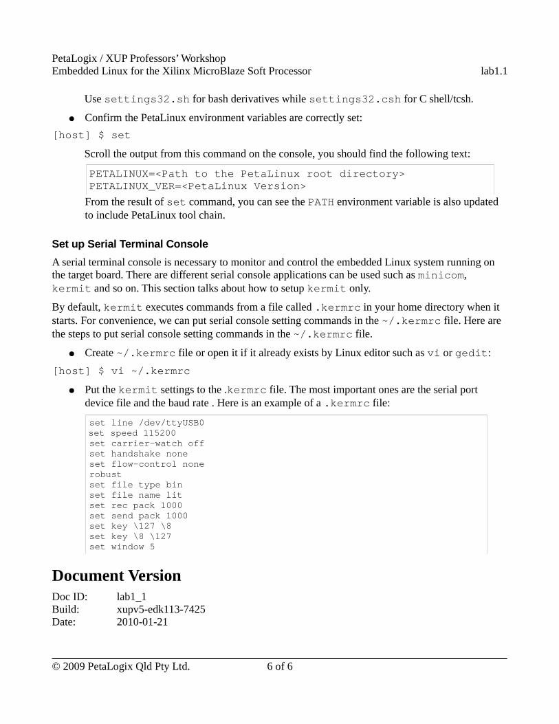
● Put the kermit settings to the .kermrc file. The most important ones are the serial port device file and the baud rate . Here is an example of a .kermrc file:
set line /dev/ttyUSB0 set speed 115200 set carrier-watch off set handshake none set flow-control none robust set file type bin set file name lit set rec pack 1000 set send pack 1000 set key \127 \8 set key \8 \127 set window 5
Document VersionDoc ID: lab1_1Build: xupv5-edk113-7425Date: 2010-01-21
© 2009 PetaLogix Qld Pty Ltd. 6 of 6
PetaLogix / XUP Professors’ WorkshopEmbedded Linux for the Xilinx MicroBlaze Soft Processor lab1.2
Lab 1.2 – Built and Boot an Image
RationaleThe most basic skill required for developing with Embedded Linux is working in the cross-compilation environment – compiling the kernel, libraries and applications, and downloading the resulting images onto the embedded target. The purpose of this lab session is to familiarize you with this process.
Objectives● Gain a basic understanding of the uCLinux configuration menus, including
○ how to configure a default uClinux kernel and user environment
● Build the Microblaze uClinux kernel and applications
● Download the resulting system image to the development board
IntroductionThis lab session will prepare you for the most basic task of working with embedded Linux – how to build and boot the operating system and applications. Small embedded Linux targets, like the MicroBlaze, are usually developed in a cross-compilation environment. This means that the kernel and applications are compiled on a development machine (in this case, a Linux PC), and then downloaded onto the target.
The standard uClinux-distribution, or “dist” for short, contains a number of tools and a configuration architecture that automates much of this process. In the following, you will learn how to use these tools, and how to download the resulting embedded Linux image onto the hardware platform.
TimeThis session will run for approximately 30 minutes.
PreparationIf this is the first lab you are doing then please refer to sections “Before You Start” of Lab 1.1 document for necessary preparatory information on how to setup the hardware environment.
© 2009 PetaLogix Qld Pty Ltd 1 of 12
PetaLogix / XUP Professors’ WorkshopEmbedded Linux for the Xilinx MicroBlaze Soft Processor lab1.2
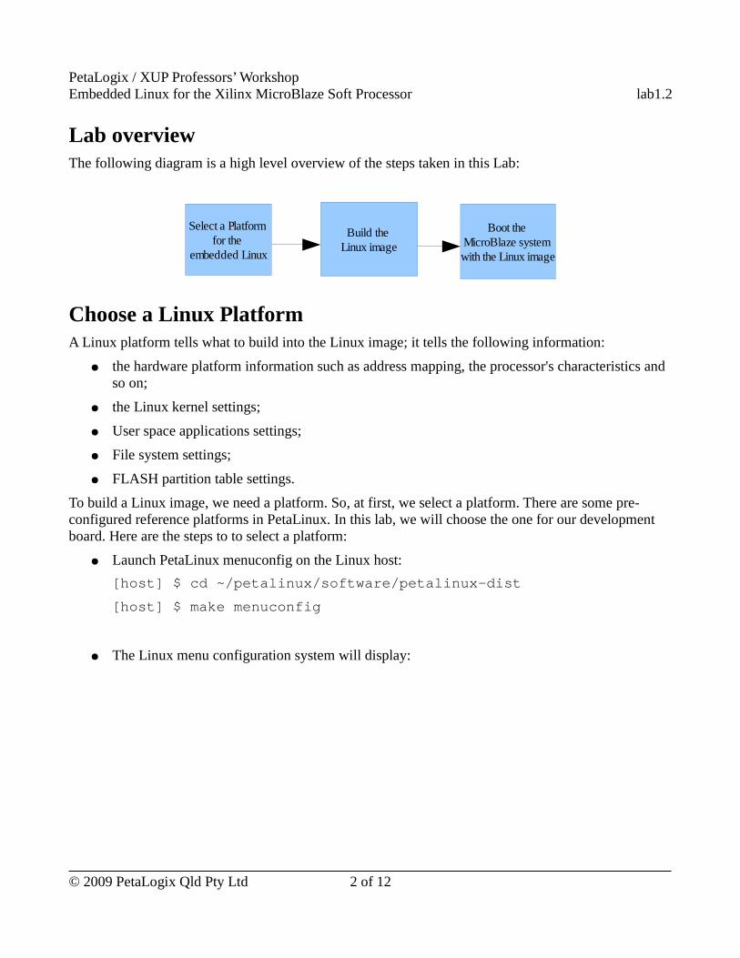
Lab overviewThe following diagram is a high level overview of the steps taken in this Lab:
Choose a Linux PlatformA Linux platform tells what to build into the Linux image; it tells the following information:
● the hardware platform information such as address mapping, the processor's characteristics and so on;
● the Linux kernel settings;
● User space applications settings;
● File system settings;
● FLASH partition table settings.
To build a Linux image, we need a platform. So, at first, we select a platform. There are some pre-configured reference platforms in PetaLinux. In this lab, we will choose the one for our development board. Here are the steps to to select a platform:
● Launch PetaLinux menuconfig on the Linux host:
[host] $ cd ~/petalinux/software/petalinux-dist
[host] $ make menuconfig
● The Linux menu configuration system will display:
© 2009 PetaLogix Qld Pty Ltd 2 of 12
Select a Platform for the
embedded Linux
Build the Linux image
Boot the MicroBlaze system with the Linux image

PetaLogix / XUP Professors’ WorkshopEmbedded Linux for the Xilinx MicroBlaze Soft Processor lab1.2
Tips:You can use arrow keys to navigate the menu. ↑↓ :scroll up and down in the menu; ← → :move left and right among <Select>, <Exit> and <Help> at the bottom;<Select>: If it is highlighted, pressing <Enter> selects the highlighted option in the menu;<Exit>: If it is highlighted, pressing <Enter> exits the menu;<Help>: If it is highlighted, pressing <Enter> shows the help text of the highlighted option in the menu.
© 2009 PetaLogix Qld Pty Ltd 3 of 12
PetaLogix / XUP Professors’ WorkshopEmbedded Linux for the Xilinx MicroBlaze Soft Processor lab1.2
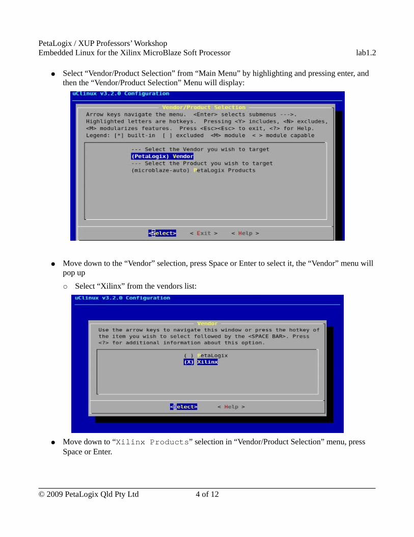
● Select “Vendor/Product Selection” from “Main Menu” by highlighting and pressing enter, and then the “Vendor/Product Selection” Menu will display:
● Move down to the “Vendor” selection, press Space or Enter to select it, the “Vendor” menu will pop up
○ Select “Xilinx” from the vendors list:
● Move down to “Xilinx Products” selection in “Vendor/Product Selection” menu, press Space or Enter.
© 2009 PetaLogix Qld Pty Ltd 4 of 12
PetaLogix / XUP Professors’ WorkshopEmbedded Linux for the Xilinx MicroBlaze Soft Processor lab1.2
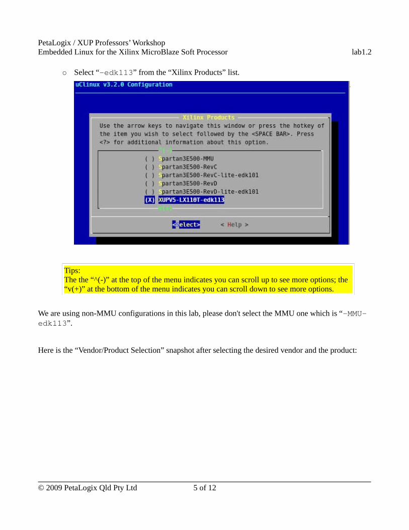
○ Select “-edk113” from the “Xilinx Products” list.
Tips:The the “^(-)” at the top of the menu indicates you can scroll up to see more options; the “v(+)” at the bottom of the menu indicates you can scroll down to see more options.
We are using non-MMU configurations in this lab, please don't select the MMU one which is “-MMU-edk113”.
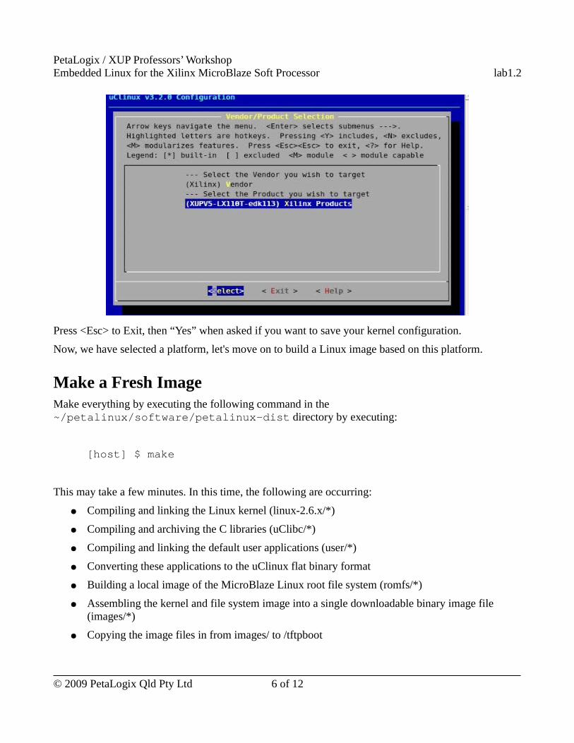
Here is the “Vendor/Product Selection” snapshot after selecting the desired vendor and the product:
© 2009 PetaLogix Qld Pty Ltd 5 of 12
PetaLogix / XUP Professors’ WorkshopEmbedded Linux for the Xilinx MicroBlaze Soft Processor lab1.2
Press <Esc> to Exit, then “Yes” when asked if you want to save your kernel configuration.
Now, we have selected a platform, let's move on to build a Linux image based on this platform.
Make a Fresh ImageMake everything by executing the following command in the ~/petalinux/software/petalinux-dist directory by executing:
[host] $ make
This may take a few minutes. In this time, the following are occurring:
● Compiling and linking the Linux kernel (linux-2.6.x/*)
● Compiling and archiving the C libraries (uClibc/*)
● Compiling and linking the default user applications (user/*)
● Converting these applications to the uClinux flat binary format
● Building a local image of the MicroBlaze Linux root file system (romfs/*)
● Assembling the kernel and file system image into a single downloadable binary image file (images/*)
● Copying the image files in from images/ to /tftpboot
© 2009 PetaLogix Qld Pty Ltd 6 of 12
PetaLogix / XUP Professors’ WorkshopEmbedded Linux for the Xilinx MicroBlaze Soft Processor lab1.2
If you are prompted to provide values for any configuration parameters, simply press enter to accept the default.
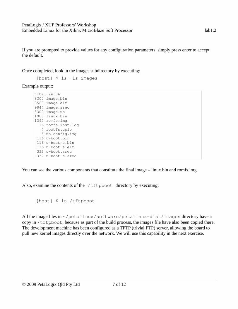
Once completed, look in the images subdirectory by executing:
[host] $ ls -1s images
Example output:
total 243363300 image.bin3568 image.elf 9844 image.srec 3300 image.ub 1908 linux.bin 1392 romfs.img 16 romfs-inst.log 4 rootfs.cpio 8 ub.config.img 116 u-boot.bin 116 u-boot-s.bin 116 u-boot-s.elf 332 u-boot.srec 332 u-boot-s.srec
You can see the various components that constitute the final image – linux.bin and romfs.img.
Also, examine the contents of the /tftpboot directory by executing:
[host] $ ls /tftpboot
All the image files in ~/petalinux/software/petalinux-dist/images directory have a copy in /tftpboot, because as part of the build process, the images file have also been copied there. The development machine has been configured as a TFTP (trivial FTP) server, allowing the board to pull new kernel images directly over the network. We will use this capability in the next exercise.
© 2009 PetaLogix Qld Pty Ltd 7 of 12
PetaLogix / XUP Professors’ WorkshopEmbedded Linux for the Xilinx MicroBlaze Soft Processor lab1.2
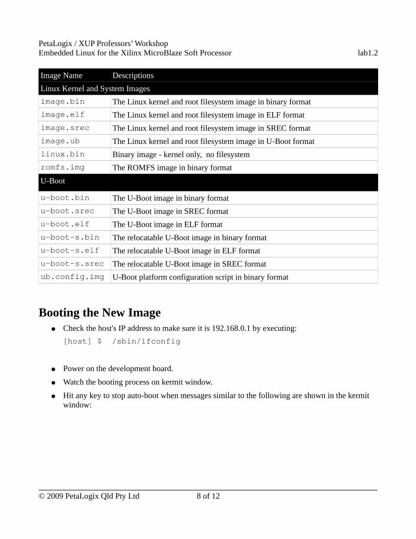
Image Name Descriptions
Linux Kernel and System Images
image.bin The Linux kernel and root filesystem image in binary format
image.elf The Linux kernel and root filesystem image in ELF format
image.srec The Linux kernel and root filesystem image in SREC format
image.ub The Linux kernel and root filesystem image in U-Boot format
linux.bin Binary image - kernel only, no filesystem
romfs.img The ROMFS image in binary format
U-Boot
u-boot.bin The U-Boot image in binary format
u-boot.srec The U-Boot image in SREC format
u-boot.elf The U-Boot image in ELF format
u-boot-s.bin The relocatable U-Boot image in binary format
u-boot-s.elf The relocatable U-Boot image in ELF format
u-boot-s.srec The relocatable U-Boot image in SREC format
ub.config.img U-Boot platform configuration script in binary format
Booting the New Image● Check the host's IP address to make sure it is 192.168.0.1 by executing:
[host] $ /sbin/ifconfig
● Power on the development board.
● Watch the booting process on kermit window.
● Hit any key to stop auto-boot when messages similar to the following are shown in the kermit window:
© 2009 PetaLogix Qld Pty Ltd 8 of 12
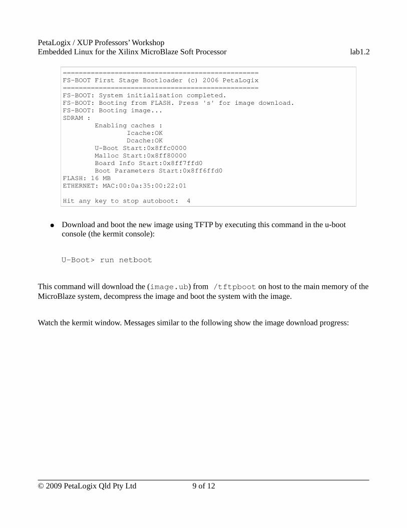
PetaLogix / XUP Professors’ WorkshopEmbedded Linux for the Xilinx MicroBlaze Soft Processor lab1.2
================================================= FS-BOOT First Stage Bootloader (c) 2006 PetaLogix ================================================= FS-BOOT: System initialisation completed. FS-BOOT: Booting from FLASH. Press 's' for image download. FS-BOOT: Booting image... SDRAM : Enabling caches : Icache:OK Dcache:OK U-Boot Start:0x8ffc0000 Malloc Start:0x8ff80000 Board Info Start:0x8ff7ffd0 Boot Parameters Start:0x8ff6ffd0 FLASH: 16 MB ETHERNET: MAC:00:0a:35:00:22:01
Hit any key to stop autoboot: 4
● Download and boot the new image using TFTP by executing this command in the u-boot console (the kermit console):
U-Boot> run netboot
This command will download the (image.ub) from /tftpboot on host to the main memory of the MicroBlaze system, decompress the image and boot the system with the image.
Watch the kermit window. Messages similar to the following show the image download progress:
© 2009 PetaLogix Qld Pty Ltd 9 of 12
PetaLogix / XUP Professors’ WorkshopEmbedded Linux for the Xilinx MicroBlaze Soft Processor lab1.2
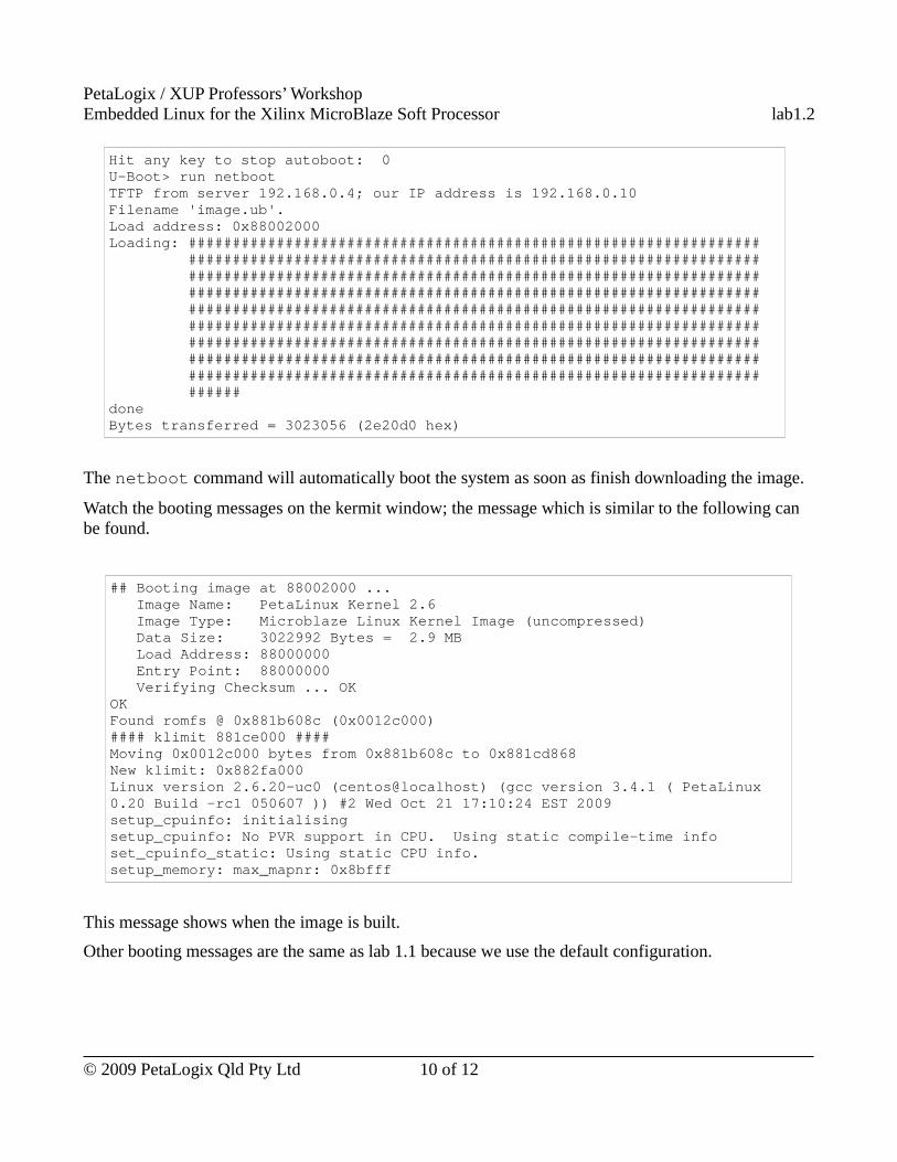
Hit any key to stop autoboot: 0 U-Boot> run netboot TFTP from server 192.168.0.4; our IP address is 192.168.0.10 Filename 'image.ub'. Load address: 0x88002000 Loading: ################################################################# ################################################################# ################################################################# ################################################################# ################################################################# ################################################################# ################################################################# ################################################################# ################################################################# ###### done Bytes transferred = 3023056 (2e20d0 hex)
The netboot command will automatically boot the system as soon as finish downloading the image.
Watch the booting messages on the kermit window; the message which is similar to the following can be found.
## Booting image at 88002000 ... Image Name: PetaLinux Kernel 2.6 Image Type: Microblaze Linux Kernel Image (uncompressed) Data Size: 3022992 Bytes = 2.9 MB Load Address: 88000000 Entry Point: 88000000 Verifying Checksum ... OK OK Found romfs @ 0x881b608c (0x0012c000) #### klimit 881ce000 #### Moving 0x0012c000 bytes from 0x881b608c to 0x881cd868 New klimit: 0x882fa000 Linux version 2.6.20-uc0 (centos@localhost) (gcc version 3.4.1 ( PetaLinux 0.20 Build -rc1 050607 )) #2 Wed Oct 21 17:10:24 EST 2009 setup_cpuinfo: initialising setup_cpuinfo: No PVR support in CPU. Using static compile-time info set_cpuinfo_static: Using static CPU info. setup_memory: max_mapnr: 0x8bfff
This message shows when the image is built.
Other booting messages are the same as lab 1.1 because we use the default configuration.
© 2009 PetaLogix Qld Pty Ltd 10 of 12
PetaLogix / XUP Professors’ WorkshopEmbedded Linux for the Xilinx MicroBlaze Soft Processor lab1.2
Move On
If you have time, try 'petalinux-jtag-boot' to boot the MicroBlaze system using JTAG.
● petalinux-jtag-boot
○ Change to “~/petalinux/hardware/reference-designs/Xilinx--edk113” directory on the Linux host by executing:
[host]$ cd ~/petalinux/hardware/reference-designs/Xilinx--edk113
○ Execute petalinux-jtag-boot to download and boot the image:
[host]$ petalinux-jtag-boot -t 0 -a 0x50000000 -i /tftpboot/image.bin
Here is the explanation of the commonly used petalinux-jtag-boot parameters:
● -t – The target CPU (0 to N-1). In this lab, we have only one MicroBlaze, we put “0” to this parameter.
● -a – The load address of the image. We use the base address of the main mememory.
● -i – image file. We use image.bin in this lab.
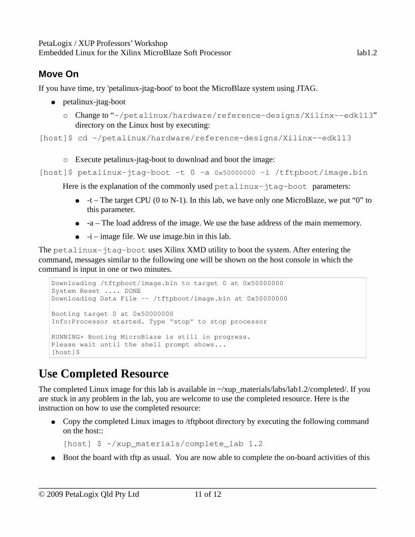
The petalinux-jtag-boot uses Xilinx XMD utility to boot the system. After entering the command, messages similar to the following one will be shown on the host console in which the command is input in one or two minutes.
Downloading /tftpboot/image.bin to target 0 at 0x50000000 System Reset .... DONE Downloading Data File -- /tftpboot/image.bin at 0x50000000
Booting target 0 at 0x50000000 Info:Processor started. Type "stop" to stop processor
RUNNING> Booting MicroBlaze is still in progress. Please wait until the shell prompt shows...[host]$
Use Completed ResourceThe completed Linux image for this lab is available in ~/xup_materials/labs/lab1.2/completed/. If you are stuck in any problem in the lab, you are welcome to use the completed resource. Here is the instruction on how to use the completed resource:
● Copy the completed Linux images to /tftpboot directory by executing the following command on the host::
[host] $ ~/xup_materials/complete_lab 1.2
● Boot the board with tftp as usual. You are now able to complete the on-board activities of this
© 2009 PetaLogix Qld Pty Ltd 11 of 12
PetaLogix / XUP Professors’ WorkshopEmbedded Linux for the Xilinx MicroBlaze Soft Processor lab1.2
lab worksheet.
OutcomesIn this lab session, you have learned how to
● select a default vendor/product combination in the configuration menu
● build a default kernel and uclinux image
● download a new image to the board, via Ethernet
These capabilities will be used in subsequent workshop lab sessions, please ask the instructors if you have any questions!
Document VersionDoc ID: lab1_2Build: xupv5-edk113-7425Date: 2010-01-21
© 2009 PetaLogix Qld Pty Ltd 12 of 12
PetaLogix / XUP Professors’ WorkshopEmbedded Linux for the Xilinx MicroBlaze Soft Processor lab1.3
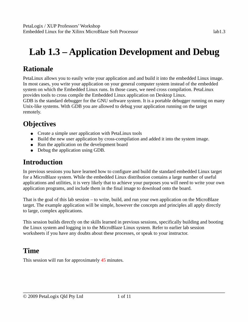
Lab 1.3 – Application Development and Debug
RationalePetaLinux allows you to easily write your application and and build it into the embedded Linux image. In most cases, you write your application on your general computer system instead of the embedded system on which the Embedded Linux runs. In those cases, we need cross compilation. PetaLinux provides tools to cross compile the Embedded Linux application on Desktop Linux.GDB is the standard debugger for the GNU software system. It is a portable debugger running on many Unix-like systems. With GDB you are allowed to debug your application running on the target remotely.
Objectives● Create a simple user application with PetaLinux tools● Build the new user application by cross-compilation and added it into the system image.● Run the application on the development board● Debug the application using GDB.
IntroductionIn previous sessions you have learned how to configure and build the standard embedded Linux target for a MicroBlaze system. While the embedded Linux distribution contains a large number of useful applications and utilities, it is very likely that to achieve your purposes you will need to write your own application programs, and include them in the final image to download onto the board.
That is the goal of this lab session – to write, build, and run your own application on the MicroBlaze target. The example application will be simple, however the concepts and principles all apply directly to large, complex applications.
This session builds directly on the skills learned in previous sessions, specifically building and booting the Linux system and logging in to the MicroBlaze Linux system. Refer to earlier lab session worksheets if you have any doubts about these processes, or speak to your instructor.
TimeThis session will run for approximately 45 minutes.
© 2009 PetaLogix Qld Pty Ltd 1 of 11
PetaLogix / XUP Professors’ WorkshopEmbedded Linux for the Xilinx MicroBlaze Soft Processor lab1.3
PreparationIf this is the first lab you are doing then please refer to sections “Before You Start” of Lab 1.1 document for necessary preparatory information on how to setup the hardware environment.
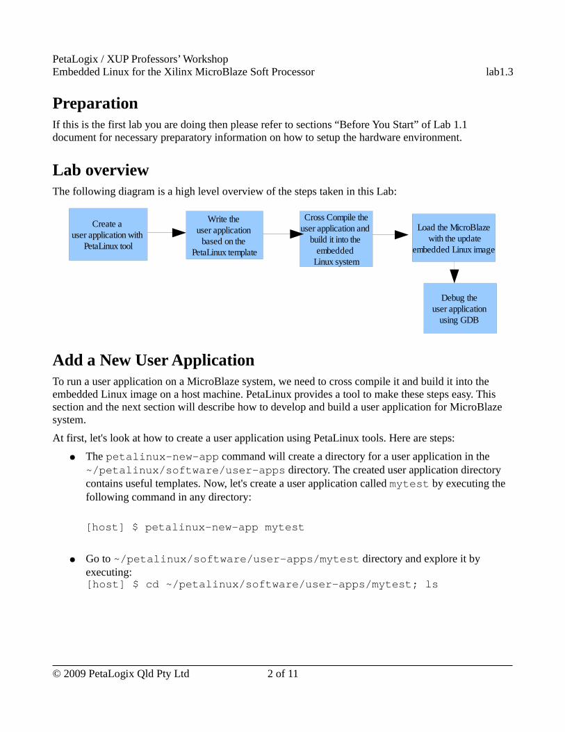
Lab overviewThe following diagram is a high level overview of the steps taken in this Lab:
Add a New User ApplicationTo run a user application on a MicroBlaze system, we need to cross compile it and build it into the embedded Linux image on a host machine. PetaLinux provides a tool to make these steps easy. This section and the next section will describe how to develop and build a user application for MicroBlaze system.
At first, let's look at how to create a user application using PetaLinux tools. Here are steps:
● The petalinux-new-app command will create a directory for a user application in the ~/petalinux/software/user-apps directory. The created user application directory contains useful templates. Now, let's create a user application called mytest by executing the following command in any directory:
[host] $ petalinux-new-app mytest
● Go to ~/petalinux/software/user-apps/mytest directory and explore it by executing:[host] $ cd ~/petalinux/software/user-apps/mytest; ls
© 2009 PetaLogix Qld Pty Ltd 2 of 11
Create a user application with
PetaLinux tool
Write the user application
based on the PetaLinux template
Cross Compile theuser application and
build it into the embedded
Linux system
Debug the user application
using GDB
Load the MicroBlaze with the update
embedded Linux image
PetaLogix / XUP Professors’ WorkshopEmbedded Linux for the Xilinx MicroBlaze Soft Processor lab1.3
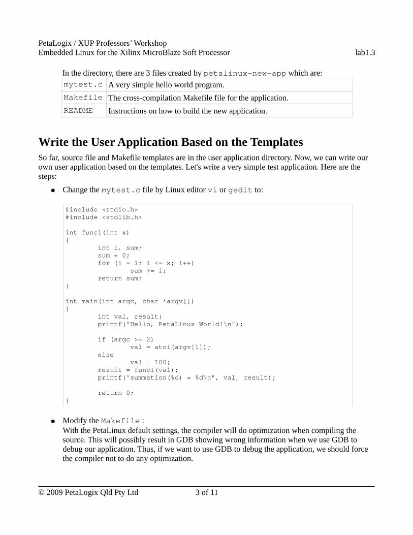
In the directory, there are 3 files created by petalinux-new-app which are:mytest.c A very simple hello world program.
Makefile The cross-compilation Makefile file for the application.
README Instructions on how to build the new application.
Write the User Application Based on the TemplatesSo far, source file and Makefile templates are in the user application directory. Now, we can write our own user application based on the templates. Let's write a very simple test application. Here are the steps:
● Change the mytest.c file by Linux editor vi or gedit to:
#include <stdio.h>#include <stdlib.h>
int func1(int x) { int i, sum; sum = 0; for (i = 1; i <= x; i++) sum += i; return sum; }
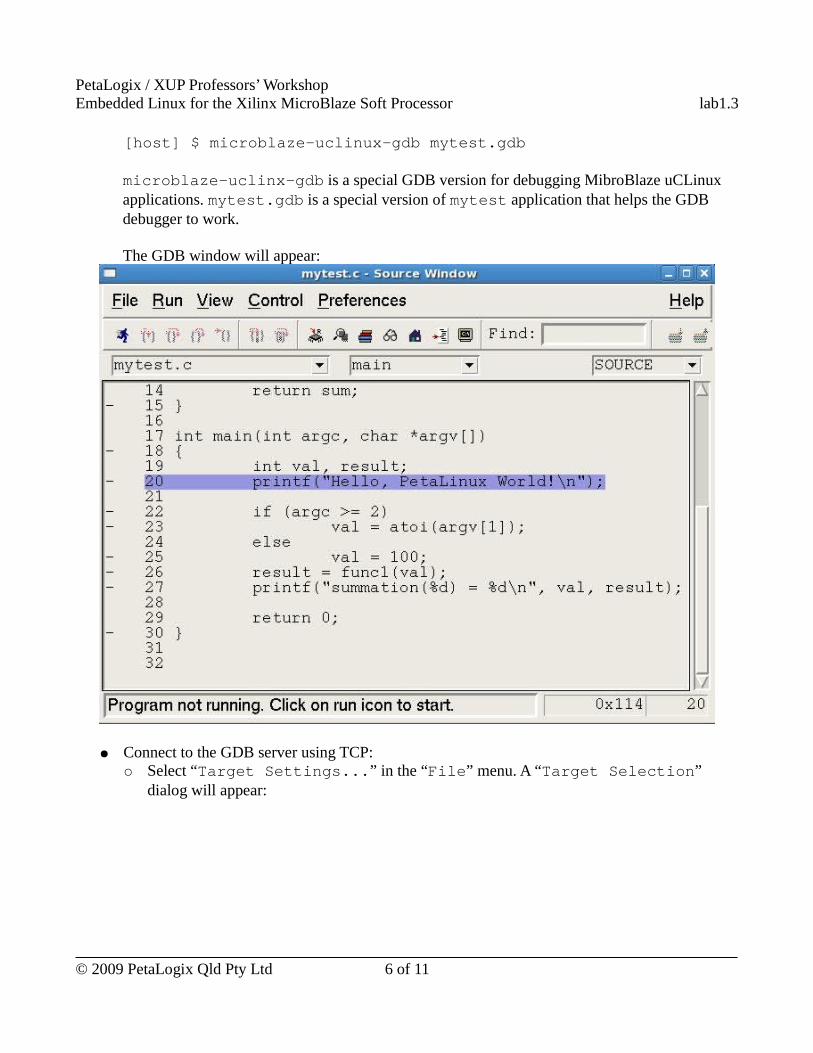
int main(int argc, char *argv[]) { int val, result; printf("Hello, PetaLinux World!\n");
if (argc >= 2) val = atoi(argv[1]); else val = 100; result = func1(val); printf("summation(%d) = %d\n", val, result);
return 0; }
● Modify the Makefile :With the PetaLinux default settings, the compiler will do optimization when compiling the source. This will possibly result in GDB showing wrong information when we use GDB to debug our application. Thus, if we want to use GDB to debug the application, we should force the compiler not to do any optimization.
© 2009 PetaLogix Qld Pty Ltd 3 of 11
PetaLogix / XUP Professors’ WorkshopEmbedded Linux for the Xilinx MicroBlaze Soft Processor lab1.3
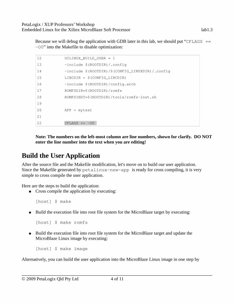
Because we will debug the application with GDB later in this lab, we should put “CFLAGS += -O0” into the Makefile to disable optimization:
12 UCLINUX_BUILD_USER = 1
13 -include $(ROOTDIR)/.config
14 -include $(ROOTDIR)/$(CONFIG_LINUXDIR)/.config
15 LIBCDIR = $(CONFIG_LIBCDIR)
16 -include $(ROOTDIR)/config.arch
17 ROMFSDIR=$(ROOTDIR)/romfs
18 ROMFSINST=$(ROOTDIR)/tools/romfs-inst.sh
19
20 APP = mytest
21
22 CFLAGS += -O0
Note: The numbers on the left-most column are line numbers, shown for clarify. DO NOT enter the line number into the text when you are editing!
Build the User ApplicationAfter the source file and the Makefile modification, let's move on to build our user application.Since the Makefile generated by petalinux-new-app is ready for cross compiling, it is very simple to cross compile the user application.
Here are the steps to build the application:● Cross compile the application by executing:
[host] $ make
● Build the execution file into root file system for the MicroBlaze target by executing:
[host] $ make romfs
● Build the execution file into root file system for the MicroBlaze target and update the MicroBlaze Linux image by executing:
[host] $ make image
Alternatively, you can build the user application into the MicroBlaze Linux image in one step by
© 2009 PetaLogix Qld Pty Ltd 4 of 11
PetaLogix / XUP Professors’ WorkshopEmbedded Linux for the Xilinx MicroBlaze Soft Processor lab1.3
executing:[host] $ make all image
Boot the Board with the New Image● Boot the board with updated image using TFTP. Please refer to the “Booting the New Image”
section in the Lab 1.2 manual for the instructions
● After the system has booted, login the system. Examine the /bin directory, you should see mytest application is there. Here is the command to see what's in the /bin directory on the kermit console:
# ls /bin
● Execute the mytest application on the kermit console:
# mytest
Here is the output of the command in the kermit console:Hello, PetaLinux World!
summation(100) = 5050
Debug the new ApplicationGDB server has already included in the system image through the default configuration. Below are the steps to use GDB:
● On the MicroBlaze kermit window, start GDB server by executing:
# gdbserver host:1234 /bin/mytest 10
This tells GDB server to listen on TCP/IP port 1234 for a remote debugging connection. Parameter “10” is passed to the mytest application. Messages similar to the following will be shown after executing the command.
# gdbserver host:1234 /bin/mytest 10
Process /bin/mytest created; pid = 54
Listening on port 1234
● On a host console, start GDB client by executing:
[host] $ cd ~/petalinux/software/user-apps/mytest
© 2009 PetaLogix Qld Pty Ltd 5 of 11
PetaLogix / XUP Professors’ WorkshopEmbedded Linux for the Xilinx MicroBlaze Soft Processor lab1.3
[host] $ microblaze-uclinux-gdb mytest.gdb
microblaze-uclinx-gdb is a special GDB version for debugging MibroBlaze uCLinux applications. mytest.gdb is a special version of mytest application that helps the GDB debugger to work.
The GDB window will appear:
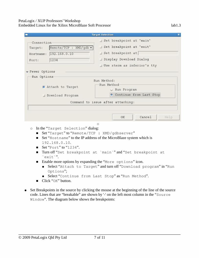
● Connect to the GDB server using TCP:○ Select “Target Settings...” in the “File” menu. A “Target Selection”
dialog will appear:
© 2009 PetaLogix Qld Pty Ltd 6 of 11
PetaLogix / XUP Professors’ WorkshopEmbedded Linux for the Xilinx MicroBlaze Soft Processor lab1.3
○
○ In the “Target Selection” dialog:■ Set “Target” to “Remote/TCP : XMD/gdbserver”■ Set “Hostname” to the IP address of the MicroBlaze system which is
192.168.0.10.■ Set “Port” to “1234”.■ Turn off “Set breakpoint at `main`” and “Set breakpoint at
`exit`”.■ Enable more options by expanding the “More options” icon.
● Select “Attach to Target” and turn off “Download program” in “Run Options”;
● Select “Continue from Last Stop” as “Run Method”.■ Click “OK” button.
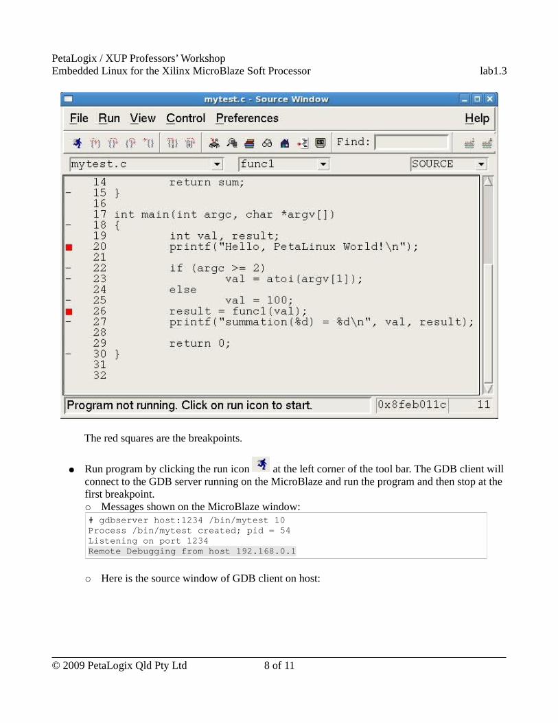
● Set Breakpoints in the source by clicking the mouse at the beginning of the line of the source code. Lines that are “breakable” are shown by '-' on the left most column in the “Source Window”. The diagram below shows the breakpoints:
© 2009 PetaLogix Qld Pty Ltd 7 of 11
PetaLogix / XUP Professors’ WorkshopEmbedded Linux for the Xilinx MicroBlaze Soft Processor lab1.3
The red squares are the breakpoints.
● Run program by clicking the run icon at the left corner of the tool bar. The GDB client will connect to the GDB server running on the MicroBlaze and run the program and then stop at the first breakpoint.○ Messages shown on the MicroBlaze window:# gdbserver host:1234 /bin/mytest 10Process /bin/mytest created; pid = 54Listening on port 1234Remote Debugging from host 192.168.0.1
○ Here is the source window of GDB client on host:
© 2009 PetaLogix Qld Pty Ltd 8 of 11
PetaLogix / XUP Professors’ WorkshopEmbedded Linux for the Xilinx MicroBlaze Soft Processor lab1.3
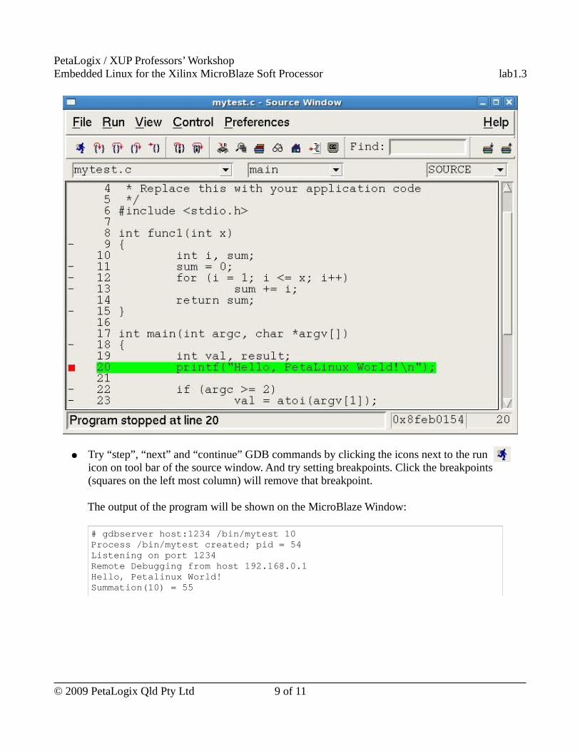
● Try “step”, “next” and “continue” GDB commands by clicking the icons next to the run icon on tool bar of the source window. And try setting breakpoints. Click the breakpoints (squares on the left most column) will remove that breakpoint.
The output of the program will be shown on the MicroBlaze Window:
# gdbserver host:1234 /bin/mytest 10Process /bin/mytest created; pid = 54Listening on port 1234Remote Debugging from host 192.168.0.1Hello, Petalinux World!Summation(10) = 55
© 2009 PetaLogix Qld Pty Ltd 9 of 11
PetaLogix / XUP Professors’ WorkshopEmbedded Linux for the Xilinx MicroBlaze Soft Processor lab1.3
● When the program finishes, the GDB server application running on MicroBlaze will exit. Message to show GDB server exit will be shown on the kermit console:# gdbserver host:1234 /bin/mytest 10Process /bin/mytest created; pid = 54Listening on port 1234Remote Debugging from host 192.168.0.1Hello, Petalinux World!Summation(10) = 55
Child exited with retcode = 0
Child exited with status 0
GDBserver exiting#
Moving On
If you have time, try GDB command line debugging.
● The debugger may also be used in command line mode, by starting it on the host with the “-nw” parameter:
[host]# microblaze-uclinux-gdb � nw mytest.gdb
● Start gdbserver on the target.
● Connect the target by entering the following command on the GDB console on the host:
(gdb) target remote 192.168.0.10:1234
● Debug the program by entering commands on the GDB console.
○ Breakpoints are set with the break command. e.g. to set a breakpoint at the start of the main() function:
(gdb) break main
○ To Continue
(gdb) continue
○ To single step, use the step command:
(gdb) step
○ To step over functions, use the next command:
© 2009 PetaLogix Qld Pty Ltd 10 of 11
PetaLogix / XUP Professors’ WorkshopEmbedded Linux for the Xilinx MicroBlaze Soft Processor lab1.3
(gdb) next
○ To exit, use the quit command:
(gdb) quit
Use Completed ResourceThe completed Linux image for this lab is available in ~/xup_materials/labs/lab1.3/completed/. If you are stuck in any problem in the lab, you are welcome to use the completed resource. Here is the instruction on how to use the completed resource:
● Copy the completed user applications to PetaLinux tree and the Linux images to /tftpboot directory by executing the following command on the host:
[host] $ ~/xup_materials/complete_lab 1.3
● Boot the board with tftp as usual. You are now able to complete the on-board activities of this lab worksheet.
OutcomesIn this lab session, you have learned how to
● Create your MicroBlaze Embedded Linux application.● Build your application and added it into the system image.● Debug your application using GDB
These capabilities are very useful, please ask the instructors if you have any questions!Note however, although GDB can be used to debug your application, print or log information whenever necessary in your application is very important for tracking issues.
Document VersionDoc ID: lab1_3Build: xupv5-edk113-7425Date: 2010-01-21
© 2009 PetaLogix Qld Pty Ltd 11 of 11
PetaLogix / XUP Professors’ WorkshopEmbedded Linux for the Xilinx MicroBlaze Soft Processor lab1.4
Lab 1.4 – Networking and TCP/IP
RationaleThe ready availability of a complete TCP/IP stack, as well as a wide array of networking applications, is a prime capability that argues in favor of using embedded Linux. This lab session will introduce you to Embedded Linux networking, and demonstrate how it can be useful both during application development and deployment.
Objectives● Explore the kernel configuration menu
○ Learn about the configuration sub-menus that enable Linux TCP/IP networking● Login to the MicroBlaze Linux system using telnet● Transfer files to and from Linux using FTP● Use NFS (Network File System) to mount your host file system on the Linux targe
○ Investigate how this capability impacts the cross-development cycle● Experiment with the embedded web server on the Linux target● Build and experiment with web-based applications under Linux
IntroductionIn the previous sessions you have already used Linux’s networking capabilities – the TFTP utility – that pulls kernel/user images over the network.
In this lab session, you will make more explicit use of the system’s networking capabilities, and in particular see how they can be used to dramatically speed up the application building/download/test cycle. We will also build a web-enabled application that can control some physical I/O on the development board. This will be a fairly simple (some might say trivial) program, but it hints at something much more powerful.
TimeThis session will run for approximately 45 minutes.
PreparationIf this is the first lab you are doing then please refer to sections “Before You Start” of Lab 1.1 document for necessary preparatory information on how to setup the hardware environment.
© 2009 PetaLogix Qld Pty Ltd 1 of 16
PetaLogix / XUP Professors’ WorkshopEmbedded Linux for the Xilinx MicroBlaze Soft Processor lab1.4
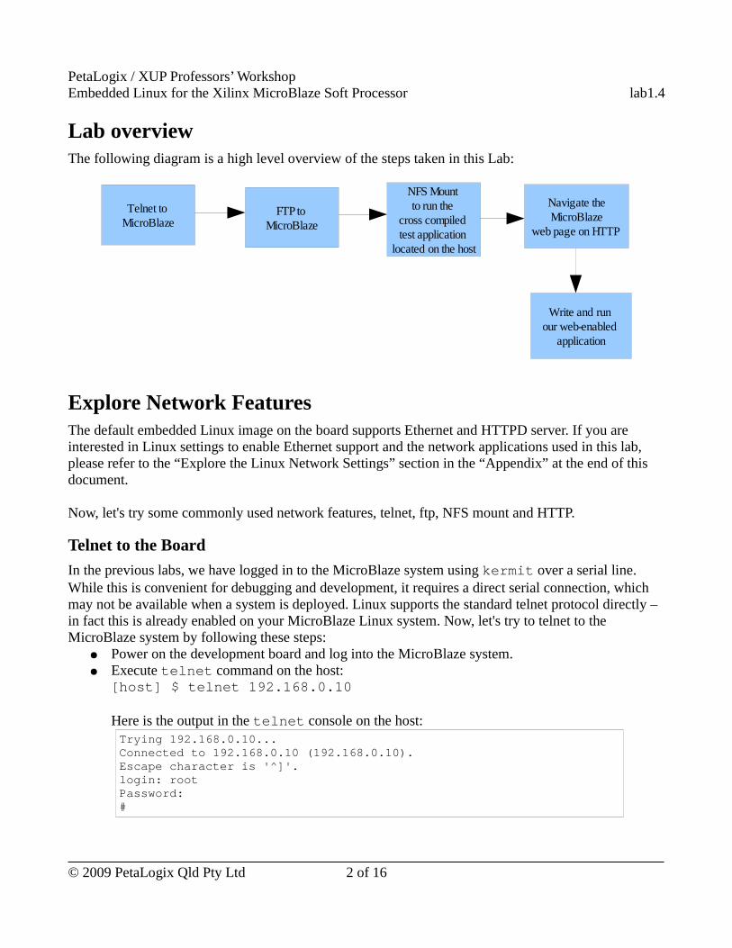
Lab overviewThe following diagram is a high level overview of the steps taken in this Lab:
Explore Network FeaturesThe default embedded Linux image on the board supports Ethernet and HTTPD server. If you are interested in Linux settings to enable Ethernet support and the network applications used in this lab, please refer to the “Explore the Linux Network Settings” section in the “Appendix” at the end of this document.
Now, let's try some commonly used network features, telnet, ftp, NFS mount and HTTP.
Telnet to the Board
In the previous labs, we have logged in to the MicroBlaze system using kermit over a serial line. While this is convenient for debugging and development, it requires a direct serial connection, which may not be available when a system is deployed. Linux supports the standard telnet protocol directly – in fact this is already enabled on your MicroBlaze Linux system. Now, let's try to telnet to the MicroBlaze system by following these steps:
● Power on the development board and log into the MicroBlaze system.● Execute telnet command on the host:
[host] $ telnet 192.168.0.10
Here is the output in the telnet console on the host:Trying 192.168.0.10...Connected to 192.168.0.10 (192.168.0.10).Escape character is '^]'.login: rootPassword:#
© 2009 PetaLogix Qld Pty Ltd 2 of 16
FTP to MicroBlaze
Telnet to MicroBlaze
NFS Mount to run the
cross compiled test application
located on the host
Navigate the MicroBlaze
web page on HTTP
Write and run our web-enabled
application
PetaLogix / XUP Professors’ WorkshopEmbedded Linux for the Xilinx MicroBlaze Soft Processor lab1.4
● We have telnet to the MicroBlaze. Try some Linux commands on the telnet console such as ls, pwd and so on.
Transferring Files with FTP
FTP is another frequently used network feature. Your MicroBlaze Linux system is also pre-configured with a FTP server. Here the steps to use the FTP:
● To connect, simply launch the ftp application from your host by executing:
[host] $ ftp 192.168.0.10
● Login as root with the root password.
You can now transfer files to and from the MicroBlaze system. If you are sending files to the MicroBlaze, remember that only the /tmp subdirectory is writable and its contents are not persistent between reboots because in this lab we are using read-only root file system on MicroBlaze.
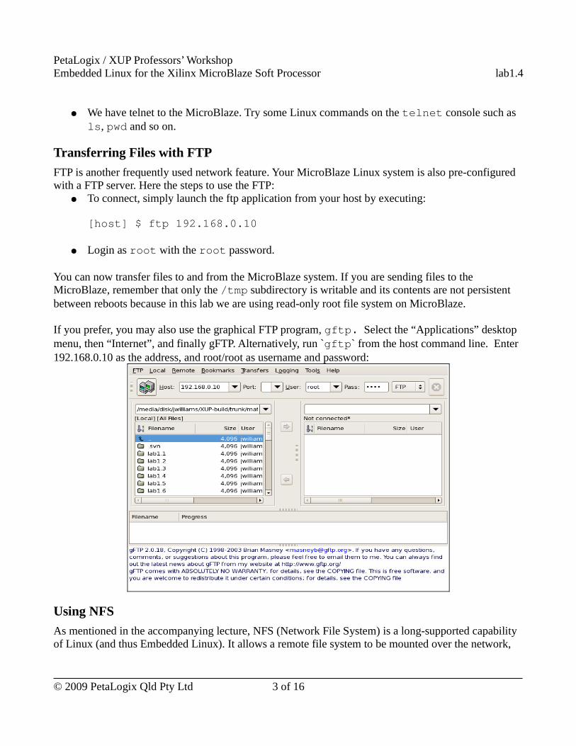
If you prefer, you may also use the graphical FTP program, gftp. Select the “Applications” desktop menu, then “Internet”, and finally gFTP. Alternatively, run `gftp` from the host command line. Enter 192.168.0.10 as the address, and root/root as username and password:
Using NFS
As mentioned in the accompanying lecture, NFS (Network File System) is a long-supported capability of Linux (and thus Embedded Linux). It allows a remote file system to be mounted over the network,
© 2009 PetaLogix Qld Pty Ltd 3 of 16
PetaLogix / XUP Professors’ WorkshopEmbedded Linux for the Xilinx MicroBlaze Soft Processor lab1.4
and used as though it were physically on the local host. In the context of cross-compiled embedded Linux systems, this can be invaluable.
NFS is very useful when you are debugging your application. Instead of rebuilding and downloading an entire image every time you make a change to your application, you can simply mount your development directory onto the MicroBlaze system. When you recompile your application, the new version is immediately available to run on the target.
Host Support
To allow your MicroBlaze system to mount a remote file system from you host, the host must be configured to allow it. This is specified in the /etc/exports file. Go and look at the contents of this file by executing:
[host] $ cat /etc/exportsYou can find this line in the file:
/home/centos 192.168.0.* (rw,sync,no_root_squash)
This says that the directory /home/centos may be exported to the machine with IP address 192.168.0.* (IP address from 192.168.0.1 to 192.168.0.255) and that it may be mounted with read-write permission.
Let’s try it out. Restart the NFS server on host:
[host] $ sudo /etc/init.d/nfs restartThis command will stop the running NFS service if there is NFS service running and then restart it. Here is the output on the host from this command:
Shutting down NFS mountd: [ OK ] Shutting down NFS daemon: [ OK ] Shutting down NFS services: [ OK ] Starting NFS services: [ OK ] Starting NFS daemon: [ OK ] Starting NFS mountd: [ OK ]
If you want to change the share folder, you should:● Edit the /etc/exports file;● Restart the NFS server by executing:
[host] $ sudo /etc/init.d/nfs restart
Now, the host allows our MicroBlaze system to NFS mount to its /home/centos directory. Let's move to NFS mount this directory on the MicroBlaze system.
© 2009 PetaLogix Qld Pty Ltd 4 of 16
PetaLogix / XUP Professors’ WorkshopEmbedded Linux for the Xilinx MicroBlaze Soft Processor lab1.4
NFS Mount on MicroBlaze
Scroll the kermit console back and take a closer look at the bootup output. You should see where the network device driver is initialized, where the Linux networking stack is configured, and, towards the end, when the “portmap” application is run. This “portmap” application is required for NFS mount.
You are now ready to mount the file system on the desktop PC on the MicroBlaze system by executing the following command on the kermit console:
# mount -t nfs 192.168.0.1:/home/centos /mnt -otcp,rsize=4096,wsize=4096
This is telling mount that ● you want to mount a file system of NFS type(-t NFS);● the host of this file system has IP address 192.168.0.1;● the directory on that host you wish to mount is /home/centos ( ie. your home directory);● you want this file system to be mounted underneath the local /mnt directory (this is known as
the “mount point”);● data transfer uses TCP protocol (-otcp);● the read and write operations should use blocks of size 4096 (-o
rsize=4096,wsize=4096). This prevents the fast desktop PC overrunning the little Microblaze target with data.
Now, change into the /mnt directory on the MicroBlaze system, and have a look around by executing:# cd /mnt# ls...#ls petalinux/software/petalinux-dist...
Does it all seem strangely familiar? It should – it’s the home directory on your desktop machine. You have read/write access, so be careful. Delete a file on this mounted NFS drive – it’s deleted from your desktop, and vice-versa.
To see how NFS mounting can be useful, on your host machine, return to the out-of-tree mytest application from an earlier Lab session by executing:
[host]$ cd ~/petalinux/software/user-apps/mytest
Similarly, on the MicroBlaze system, find the equivalent NFS directory by executing the following command on the kermit console:
# cd /mnt/petalinux/software/user-apps/mytest
© 2009 PetaLogix Qld Pty Ltd 5 of 16
PetaLogix / XUP Professors’ WorkshopEmbedded Linux for the Xilinx MicroBlaze Soft Processor lab1.4
You should be able to run the hello application directly over the network by executing:
# ./mytest
Try making some changes to the mytest.c file, e.g. change “printf(“Hello, Petalinux World!\n”)” to “printf(“Hello, Welcome to XUP workshop!\n”)”, and then rebuild it on the host by executing:
[host] $ vi mytest.c&[host] $ make
Then, run it again on MicroBlaze over the NFS mount by executing the following command in /mnt/petalinux/software/user-apps/mytest directory:
# ./mytest
The output of the application should change to “Hello, Welcome to XUP workshop!”.Any changes made on the host to the application can be tested on MicroBlaze immediately over NFS mount!
Embedded Web Server
More and more embedded systems and applications are becoming web-enabled, allowing for remote control, management, and monitoring. In this exercise, you will experiment with the httpd.
Firstly, reboot the development board by power it off and power it on again. It is not necessary to login yet. At the bottom of the boot-up messages, you can see the httpd has been started during boot.
On your host machine, open up a web browser, and point it to the following URL:
http://192.168.0.10
You will see the default placeholder page which is installed on the MicroBlaze Linux system. Logon to the MicroBlaze, and explore the /home subdirectory by executing:
# cd /home# ls
httpd
# ls httpd
© 2009 PetaLogix Qld Pty Ltd 6 of 16
PetaLogix / XUP Professors’ WorkshopEmbedded Linux for the Xilinx MicroBlaze Soft Processor lab1.4
index.html
# cat httpd/index.html...
Back on the host, to change or add static HTML pages, we must do so on the host. These files live in the ~/petalinux/software/petalinux-dist/vendors/PetaLogix/common/http-content directory. Have a look at what is in the http-content directory by executing:
[host]$ cd ~/petalinux/software/petalinux-dist/vendors/PetaLogix/common/http-content
[host]$ ls
Here are what are in the directory:
cgi-bin images index.html
Feel free to edit index.html, or add new HTML files – they will be automatically included when you rebuild the MicroBlaze root file system and the MicroBlaze Linux image by executing:
[host]$ cd ~/petalinux/software/petalinux-dist[host]$ make romfs image
To try your new HTML file, you can reboot the MicroBlaze with the new MicroBlaze Linux image using tftp (Please refer to “Booting the New Image” section in the Lab 1.2 manual for the instructions), and then navigate to the updated/new HTML file(s) on your host's web browser.. If you have changed the index.html but you cannot see the updated web page on your host's web browser, it is probably because your browser doesn't get the new page from the web server on the board. In this case, clear the private data of your web browser:
● Select “Tools” --> “Clear Private Data” on Firefox's menu bar.
Web-enabled applications
Web serving embedded applications become a lot more useful when the web interface can be used to control the device, or monitor sensor inputs. In this exercise you will build and experiment with a simple web-enabled application on the MicroBlaze system.
© 2009 PetaLogix Qld Pty Ltd 7 of 16
PetaLogix / XUP Professors’ WorkshopEmbedded Linux for the Xilinx MicroBlaze Soft Processor lab1.4
The Sample Program
We have a sample CGI application to control the on/off of LEDs on the board. Let's try to build this program and run it step by step:
● Copy the cgi-leds application from the Lab 1.4 materials to the user-apps of the PetaLinux tree by executing the following commands on the host machine:
[host] $ cd ~/petalinux/software/user-apps[host] $ cp -r ~/xup-materials/labs/lab1.4/resources/user-apps/cgi-leds ./
● Change to the user-apps/cgi-leds directory of the PetaLinux tree on the host machine by executing:
[host] $ cd ~/petalinux/software/user-apps/cgi-leds
The main application are composed of cgi_leds.c and led.cgi.c; other files are for a small CGI library.
● Compile the application and update the MicroBlaze Linux image by executing:
[host] $ make all image
● Reboot the board with updated image using tftp. Please refer to the “Booting the New Image” section in the Lab 1.2 manual for the instructions.
● Once the board reboots, point the web browser on the host back to the board:
http://192.168.0.10
Again, the index page will display. Append the path to our new led.cgi application, to the URL:
http://192.168.0.10/cgi-bin/led.cgi
● Try the demo web page:Press the “ON/OFF” on the web page and watch what happens on the board and the web page.
Manually entering the URL to the cgi-bin applications is a bit tedious – try editing the index.html file (It is in ~/petalinux/software/petalinux-dist/vendors/PetaLogix/common/http-content directory) to include a link to the script. An HTML snippet like this should do the trick:
<a href=cgi-bin/led.cgi>Go Blinken-demo!</a>
© 2009 PetaLogix Qld Pty Ltd 8 of 16
PetaLogix / XUP Professors’ WorkshopEmbedded Linux for the Xilinx MicroBlaze Soft Processor lab1.4
Don’t forget you’ll need to regenerate the romfs and update the MicroBlaze Linux image to include both the new index.html and the led.cgi after changing the original index.html file. Here is the steps to do it after you finish editing the index.html file:
[host] $ cd ~/petalinux/software/petalinux-dist[host] $ make romfs[host] $ cd ~/petalinux/software/user-apps/cgi-leds[host] $ make romfs image
After rebuilding the image, reboot the board with the new image. This time, you should be able to enter the LED demo web page by clicking the link on the updated home page.
Use Completed ResourceThe completed Linux image for this lab is available in ~/xup_materials/labs/lab1.4/completed/. If you are stuck in any problem in the lab, you are welcome to use the completed resource. Here is the instruction on how to use the completed resource:
● Copy the completed user applications to PetaLinux tree and Linux images to /tftpboot directory by executing the following command on the host:
[host] $ ~/xup_materials/complete_lab 1.4
● Boot the board with tftp as usual. You are now able to complete the on-board activities of this lab worksheet.
OutcomesAt the completion of this lab you should
● Understand how to use NFS to mount your development system onto the Linux target;● Have experience in executing a Linux application directly over the NFS mount, instead of
updating and downloading an entirely new image file;● Understand how to create and modify simple static HTML pages so that they can be served by
the embedded web server;● Have a basic understanding of simple web-enabled applications running on the Linux target.
Appendix
Explore the Linux Network Settings
The MicroBlaze Linux system has been configured to support all the network operations we use in this lab. This section is to show you where these network related configurations are in the menuconfig
© 2009 PetaLogix Qld Pty Ltd 9 of 16
PetaLogix / XUP Professors’ WorkshopEmbedded Linux for the Xilinx MicroBlaze Soft Processor lab1.4
such that you know how to configure Linux to support network in future when you configure your own embedded Linux with PetaLinux tools.
! Please don't change anything in menuconfig, navigate only!
Embedded Linux Kernel Settings to Support Network
This section gives instructions on how to configure embedded Linux kernel to support Network. Here are the instructions:
● Run menuconfig on the host by executing:[host] $ cd ~/petalinux/software/petalinux-dist[host] $ make menuconfig
● In the pop-up configuration window, select ` Kernel/Library/Defaults Selection ` --> `Customize Kernel Settings`:[*] Customize Kernel Settings
● Exit the menu and select “Yes” to “save your new kernel configuration”, the “Linux Kernel Configuration” menu window will pop up.
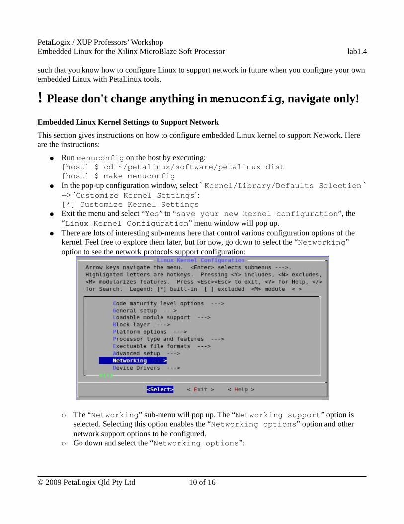
● There are lots of interesting sub-menus here that control various configuration options of the kernel. Feel free to explore them later, but for now, go down to select the “Networking” option to see the network protocols support configuration:
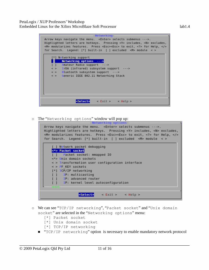
○ The “Networking” sub-menu will pop up. The “Networking support” option is selected. Selecting this option enables the “Networking options” option and other network support options to be configured.
○ Go down and select the “Networking options”:
© 2009 PetaLogix Qld Pty Ltd 10 of 16
PetaLogix / XUP Professors’ WorkshopEmbedded Linux for the Xilinx MicroBlaze Soft Processor lab1.4
○ The “Networking options” window will pop up:
○ We can see “TCP/IP networking”, “Packet socket” and “Unix domain socket” are selected in the “Networking options” menu:
[*] Packet socket[*] Unix domain socket[*] TCP/IP networking
■ “TCP/IP networking” option is necessary to enable mandatory network protocol
© 2009 PetaLogix Qld Pty Ltd 11 of 16
PetaLogix / XUP Professors’ WorkshopEmbedded Linux for the Xilinx MicroBlaze Soft Processor lab1.4
support in embedded Linux. To see more information about each option, go down to that option and then enter <?> or <h> for help.
■ Even though “Packet socket” is not required for most operations - the most that is required is to enable main “TCP/IP networking” - it is selected because some applications communicate directly with the network without an intermediate network protocol implemented in the kernel, e.g. NFS.
■ “Unix domain socket” option is to support Unix domain sockets. It is required to some commonly used network applications such as ssh. But it is not necessary for this lab.
● A network device driver is also required to connect the TCP/IP stack and the physical Ethernet device. The network device driver depends on the Ethernet device hardware. In this workshop, because we use Xilinx LL_TEMAC as the network adapter, the “Xilinx 10/100/1000 EMACLITE” driver is selected by default. Here is where the “Xilinx 10/100/1000 EMACLITE” driver is in menuconfig:
Linux Kernel Configuration -> Device Drivers -> Network device support -> Ethernet (10 or 100Mbit) -> Xilinx 10/100/1000 EMACLITE support.
● Exit from the kernel configuration, and don’t save any changes (you shouldn’t have made any!).
Embedded Linux Kernel Settings to Support NFSAs mentioned in the previous section “Embedded Linux Kernel Settings to Support Network”, “Packet socket” is required in networking support configuration to support NFS. Besides, Linux kernel file system configuration is also required to configured to support NFS file system. Here are the instructions on Linux kernel file system configuration to support NFS:
● From the main kernel configuration menu (“Linux Kernel Configuration” menu), scroll down and select the “File Systems” sub-menu.
● The “File Systems” menu will show up. This is where you can configure which of the many supported file systems to build into your kernel:
© 2009 PetaLogix Qld Pty Ltd 12 of 16
PetaLogix / XUP Professors’ WorkshopEmbedded Linux for the Xilinx MicroBlaze Soft Processor lab1.4
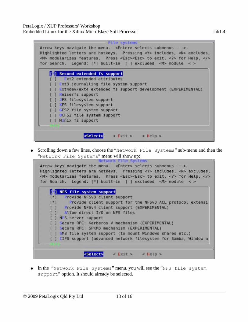
● Scrolling down a few lines, choose the “Network File Systems” sub-menu and then the “Network File Systems” menu will show up:
● In the “Network File Systems” menu, you will see the “NFS file system support” option. It should already be selected.
© 2009 PetaLogix Qld Pty Ltd 13 of 16
PetaLogix / XUP Professors’ WorkshopEmbedded Linux for the Xilinx MicroBlaze Soft Processor lab1.4
● Exit from the kernel configuration, and don’t save any changes (you shouldn’t have made any!).
User Space Networking Applications ConfigurationTelnet server, FTP server, NFS mount and web server are all user space applications. There are many more user space networking applications. This section tells you where the network applications are in menuconfig such that you can select to build them into the embedded Linux system. Let's start exploring the menuconfig to look for those network applications:
● Run menuconfig on the host by executing:[host] $ cd ~/petalinux/software/petalinux-dist[host] $ make menuconfig
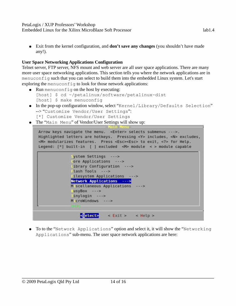
● In the pop-up configuration window, select “Kernel/Library/Defaults Selection” --> “Customize Vendor/User Settings”:[*] Customize Vendor/User Settings
● The “Main Menu” of Vendor/User Settings will show up:
● To to the “Network Applications” option and select it, it will show the “Networking Applications” sub-menu. The user space network applications are here:
© 2009 PetaLogix Qld Pty Ltd 14 of 16
PetaLogix / XUP Professors’ WorkshopEmbedded Linux for the Xilinx MicroBlaze Soft Processor lab1.4
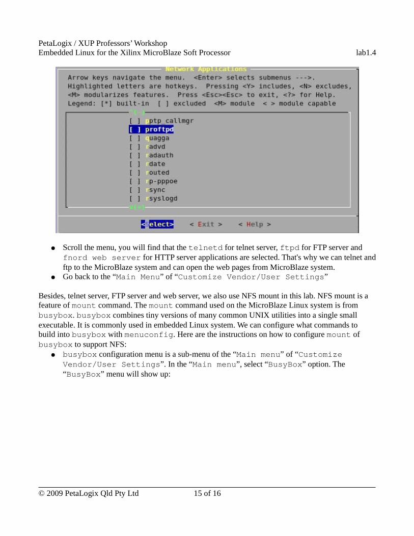
● Scroll the menu, you will find that the telnetd for telnet server, ftpd for FTP server and fnord web server for HTTP server applications are selected. That's why we can telnet and ftp to the MicroBlaze system and can open the web pages from MicroBlaze system.
● Go back to the “Main Menu” of “Customize Vendor/User Settings”
Besides, telnet server, FTP server and web server, we also use NFS mount in this lab. NFS mount is a feature of mount command. The mount command used on the MicroBlaze Linux system is from busybox. busybox combines tiny versions of many common UNIX utilities into a single small executable. It is commonly used in embedded Linux system. We can configure what commands to build into busybox with menuconfig. Here are the instructions on how to configure mount of busybox to support NFS:
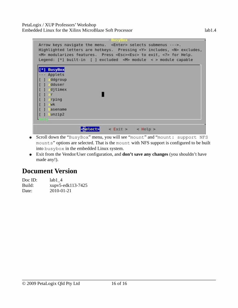
● busybox configuration menu is a sub-menu of the “Main menu” of “Customize Vendor/User Settings”. In the “Main menu”, select “BusyBox” option. The “BusyBox” menu will show up:
© 2009 PetaLogix Qld Pty Ltd 15 of 16
PetaLogix / XUP Professors’ WorkshopEmbedded Linux for the Xilinx MicroBlaze Soft Processor lab1.4
● Scroll down the “BusyBox” menu, you will see “mount” and “mount: support NFS mounts” options are selected. That is the mount with NFS support is configured to be built into busybox in the embedded Linux system.
● Exit from the Vendor/User configuration, and don’t save any changes (you shouldn’t have made any!).
Document VersionDoc ID: lab1_4Build: xupv5-edk113-7425Date: 2010-01-21
© 2009 PetaLogix Qld Pty Ltd 16 of 16
PetaLogix / XUP Professors’ WorkshopEmbedded Linux for the Xilinx MicroBlaze Soft Processor lab1.5
Lab 1.5 – Your first kernel module
RationaleA lot of Embedded Linux kernel device drivers are developed as kernel modules, such as the Ethernet adapter driver. If a kernel is configured to allow loadable modules, after the kernel boots we can load or unload a module at run time.
Objectives● Create a simple kernel module using PetaLinux tools.● Experience the load module command and unload module command
IntroductionIf a kernel is configured to allow loadable modules, users are able to load kernel modules after the kernel is booted.
In this lab session, you will create your first very simple kernel module and learn how to load a module and unload a module in Linux.
TimeThis session will run for approximately 45 minutes.
PreparationIf this is the first lab you are doing then please refer to sections “Before You Start” of Lab 1.1 document for necessary preparatory information on how to setup the hardware environment.
© 2009 PetaLogix Qld Pty Ltd 1 of 11
PetaLogix / XUP Professors’ WorkshopEmbedded Linux for the Xilinx MicroBlaze Soft Processor lab1.5
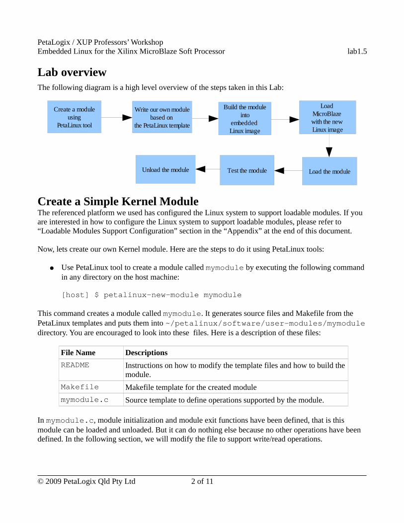
Lab overviewThe following diagram is a high level overview of the steps taken in this Lab:
Create a Simple Kernel ModuleThe referenced platform we used has configured the Linux system to support loadable modules. If you are interested in how to configure the Linux system to support loadable modules, please refer to “Loadable Modules Support Configuration” section in the “Appendix” at the end of this document.
Now, lets create our own Kernel module. Here are the steps to do it using PetaLinux tools:
● Use PetaLinux tool to create a module called mymodule by executing the following command in any directory on the host machine:
[host] $ petalinux-new-module mymodule
This command creates a module called mymodule. It generates source files and Makefile from the PetaLinux templates and puts them into ~/petalinux/software/user-modules/mymodule directory. You are encouraged to look into these files. Here is a description of these files:
File Name Descriptions
README Instructions on how to modify the template files and how to build the module.
Makefile Makefile template for the created module
mymodule.c Source template to define operations supported by the module.
In mymodule.c, module initialization and module exit functions have been defined, that is this module can be loaded and unloaded. But it can do nothing else because no other operations have been defined. In the following section, we will modify the file to support write/read operations.
© 2009 PetaLogix Qld Pty Ltd 2 of 11
Create a module using
PetaLinux tool
Write our own modulebased on
the PetaLinux template
Build the module into
embedded Linux image
Test the module Load the module
Load MicroBlaze with the new Linux image
Unload the module
PetaLogix / XUP Professors’ WorkshopEmbedded Linux for the Xilinx MicroBlaze Soft Processor lab1.5
Write a Simple Virtual Miscellaneous Device DriverNow let's make the module capable of doing something.
Miscellaneous device is a type of character device. It can be accessed by specifying a device name through file system. To make the simplest workable miscellaneous device driver, we need to :
● Register the device;● implement the the very basic file operations: open(), release(), read() and write().
The source files are already in ~/xup-materials/labs/lab1.5/resources/user-modules/mymodule directory. Please copy those files to the mymodule directory you have created by executing (all in one line):
[host] $ cp ~/xup-materials/labs/lab1.5/resources/user-modules/mymodule/* ~/petalinux/software/user-modules/mymodule/
You are encouraged to go through these source files and the Makefile.
Below is a description about the changes to the template files.● mymodule.c
○ Module initialization function – Changed to initialize the device resources and register the devices. A device has to be registered to use.
○ Module exit function – Changed to unregister the devices and free resources.○ Open function – This function will be called when the device file is opened.○ Release function – This function will be called when the device file is closed.○ Read function – Retrieve data from device.○ Write function – Send data to device.Because the module is a fake device, a buffer acts as the data storage of the device.
● MakefileBecause our Embedded Linux system is a read-only system, it is not allowed to make a node in /dev directory after the system is booted, the device file has to be added into the the system image during compilation. The modification in Makefile is on this purpose. Here is the line in Makefile to define a device file:
DEVICES = mymodule0,c,10,128
Each “field” in the above definition is described as follows:○ “mymodule0” is the device name○ “c” indicates it is a character device○ “10” is the major number of the device. Miscellaneous devices' major number is 10.○ “128” is the minor number of the device which is used by the kernel to determine
exactly which device is being referred to.
© 2009 PetaLogix Qld Pty Ltd 3 of 11
PetaLogix / XUP Professors’ WorkshopEmbedded Linux for the Xilinx MicroBlaze Soft Processor lab1.5
Target romfs in the template Makefile is to put the module file to the root file system. It has been changed to add the device file to the root file system as well. Here is the command defined in the romfs target in mymodule/Makefile to generate the device file to the root file system:for i in $(DEVICES); do \ touch $(ROMFSDIR)/dev/@$$i; \ done
The above command will add the device file to the /dev directory in the root file system.
Build the module We have developed a simple virtual miscellaneous device driver. Now, let's build the driver. Here are the steps:
● Compile mymodule by executing:
[host] $ cd ~/petalinux/software/user-modules/mymodule[host] $ makeA module file mymodule.ko is generated.
● Add the module and its device file into the MicroBlaze root file system system and update the MicroBlaze Linux image by executing:
[host] $ make image
Alternatively, you can compile the module, update the MicroBlaze root file system and the MicroBlaze Linux image in only one step by executing:
[host] $ make all image
Create a New User Application to Test the ModuleAfter we developed a module, we need a test application to test it.
● In Lab 1.3, we have learned how to create a new application with PetaLinux tools. Now let's create a test application with what we have learned. Type the following command on the host:
[host] $ petalinux-new-app testmymodule
Directory ~/petalinux/software/user-apps/testmymodule directory containing the template source file and Makefile will be created.
● The test application is already in ~/xup-materials/labs/lab1.5/resources/user-apps/testmymodule directory. Copy it to your newly created testmymodule directory by executing:
© 2009 PetaLogix Qld Pty Ltd 4 of 11
PetaLogix / XUP Professors’ WorkshopEmbedded Linux for the Xilinx MicroBlaze Soft Processor lab1.5
[host] $ cd ~/petalinux/software/user-apps/testmymodule
[host] $ cp ~/xup-materials/labs/lab1.5/resources/user-apps/testmymodule/* ./
This test application takes the command parameter as an input string, writes that string to /dev/mymodule0 device and then reads the string back from the device.
● Now, build the test application and update the MicroBlaze root file system and the MicroBlaze Linux image by executing:
[host] $ make all image
Load and Unload a ModuleSo far, the MicroBlaze Linux image with our own module and the test application is ready, it is time to test our module. In this section, we will load our module, test the module and in the end, unload it.
Here are the steps:
● reboot the development board with the new MicroBlaze Linux image using TFTP as we have learned in the “Booting the New Image” section in Lab 1.2.
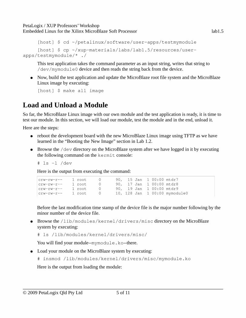
● Browse the /dev directory on the MicroBlaze system after we have logged in it by executing the following command on the kermit console:
# ls -l /dev
Here is the output from executing the command:
crw-rw-r-- 1 root 0 90, 15 Jan 1 00:00 mtdr7 crw-rw-r-- 1 root 0 90, 17 Jan 1 00:00 mtdr8 crw-rw-r-- 1 root 0 90, 19 Jan 1 00:00 mtdr9 crw-rw-r-- 1 root 0 10, 128 Jan 1 00:00 mymodule0
Before the last modification time stamp of the device file is the major number following by the minor number of the device file.
● Browse the /lib/modules/kernel/drivers/misc directory on the MicroBlaze system by executing:
# ls /lib/modules/kernel/drivers/misc/
You will find your module--mymodule.ko--there.
● Load your module on the MicroBlaze system by executing:
# insmod /lib/modules/kernel/drivers/misc/mymodule.ko
Here is the output from loading the module:
© 2009 PetaLogix Qld Pty Ltd 5 of 11
PetaLogix / XUP Professors’ WorkshopEmbedded Linux for the Xilinx MicroBlaze Soft Processor lab1.5
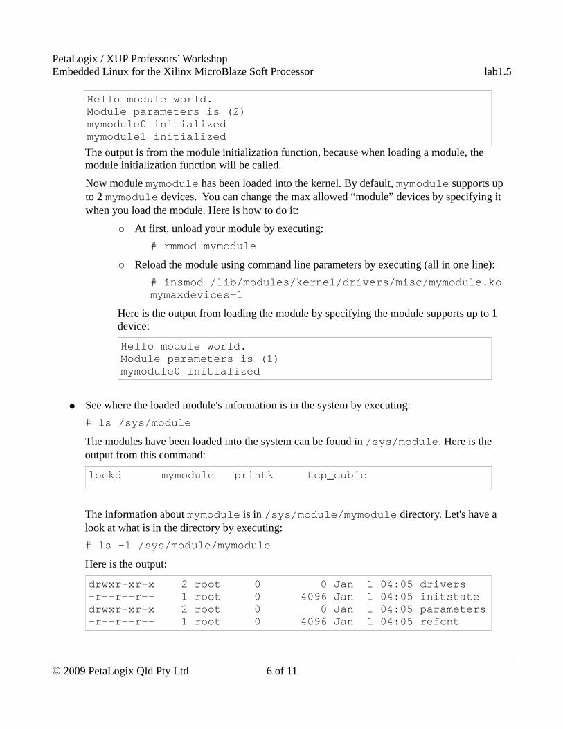
Hello module world. Module parameters is (2) mymodule0 initialized mymodule1 initialized
The output is from the module initialization function, because when loading a module, the module initialization function will be called.
Now module mymodule has been loaded into the kernel. By default, mymodule supports up to 2 mymodule devices. You can change the max allowed “module” devices by specifying it when you load the module. Here is how to do it:
○ At first, unload your module by executing:
# rmmod mymodule
○ Reload the module using command line parameters by executing (all in one line):
# insmod /lib/modules/kernel/drivers/misc/mymodule.ko mymaxdevices=1
Here is the output from loading the module by specifying the module supports up to 1 device:
Hello module world. Module parameters is (1) mymodule0 initialized
● See where the loaded module's information is in the system by executing:
# ls /sys/module
The modules have been loaded into the system can be found in /sys/module. Here is the output from this command:
lockd mymodule printk tcp_cubic
The information about mymodule is in /sys/module/mymodule directory. Let's have a look at what is in the directory by executing:
# ls -l /sys/module/mymodule
Here is the output:
drwxr-xr-x 2 root 0 0 Jan 1 04:05 drivers -r--r--r-- 1 root 0 4096 Jan 1 04:05 initstate drwxr-xr-x 2 root 0 0 Jan 1 04:05 parameters -r--r--r-- 1 root 0 4096 Jan 1 04:05 refcnt
© 2009 PetaLogix Qld Pty Ltd 6 of 11
PetaLogix / XUP Professors’ WorkshopEmbedded Linux for the Xilinx MicroBlaze Soft Processor lab1.5
Here is a brief description of these files/directories:
File/Directory Name Description
drivers The drivers belong to the module.
initstate The state of the module initialization.
parameters The value of the input parameters to load the module.
refcnt The number of memory reference counters.
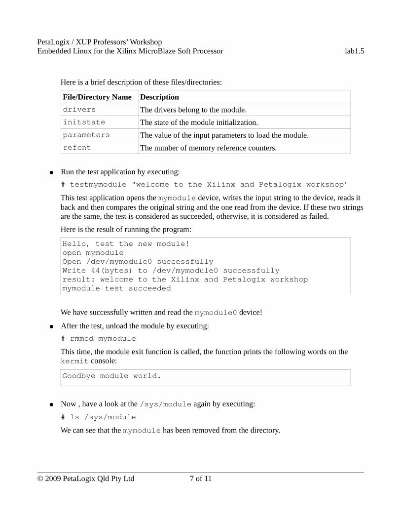
● Run the test application by executing:
# testmymodule "welcome to the Xilinx and Petalogix workshop"
This test application opens the mymodule device, writes the input string to the device, reads it back and then compares the original string and the one read from the device. If these two strings are the same, the test is considered as succeeded, otherwise, it is considered as failed.
Here is the result of running the program:
Hello, test the new module! open mymodule Open /dev/mymodule0 successfully Write 44(bytes) to /dev/mymodule0 successfully result: welcome to the Xilinx and Petalogix workshop mymodule test succeeded
We have successfully written and read the mymodule0 device!
● After the test, unload the module by executing:
# rmmod mymodule
This time, the module exit function is called, the function prints the following words on the kermit console:
Goodbye module world.
● Now , have a look at the /sys/module again by executing:
# ls /sys/module
We can see that the mymodule has been removed from the directory.
© 2009 PetaLogix Qld Pty Ltd 7 of 11
PetaLogix / XUP Professors’ WorkshopEmbedded Linux for the Xilinx MicroBlaze Soft Processor lab1.5
Use Completed ResourceThe completed Linux image for this lab is available in ~/xup_materials/labs/lab1.5/completed/. If you are stuck in any problem in the lab, you are welcome to use the completed resource. Here is the instructions on how to use the completed resource:
● Copy the completed user applications and user modules to PetaLinux tree and the Linux images to /tftpboot directory by executing the following command on the host:
[host] $ ~/xup_materials/complete_lab 1.5
● Boot the board with tftp as usual. You may now complete the on-board activities of this lab worksheet.
OutcomesAt the completion of this lab you should know
● how to configure the kernel to support loadable modules● how to create a simple module● how to add a device node in romfs system.● how to load and unload a module● where to find the module information
Appendix
Loadable Modules Support Configuration
The MicroBlaze Linux system has been configured to support loadable modules in this workshop. This section is to show you where these configurations are in the menuconfig such that you know how to configure Linux to support loadable in future when you configure your own embedded Linux with PetaLinux tools.
! Please don't change anything in menuconfig, navigate only!
To support loadable modules, both the Linux kernel settings and the user space application settings are required to be configured properly to support it.
In this section, we will look at how to configure the Linux kernel to support loadable modules and then look at what user space applications should be configured to load and unload modules.
Kernel Settings for Supporting Loadable Modules
We will navigate the configuration of the referenced platform used in this lab to learn how to configure the Linux Kernel to support loadable modules:
© 2009 PetaLogix Qld Pty Ltd 8 of 11
PetaLogix / XUP Professors’ WorkshopEmbedded Linux for the Xilinx MicroBlaze Soft Processor lab1.5
● Run menuconfig on the host by executing:[host] $ cd ~/petalinux/software/petalinux-dist[host] $ make menuconfig
● In the pop-up configuration window, select “Kernel/Library/Defaults Selection” --> “Customize Kernel Settings”:[*] Customize Kernel Settings
● Exit the menu and select “Yes” to “save your new kernel configuration”, the “Linux Kernel Configuration” menu window will pop up.
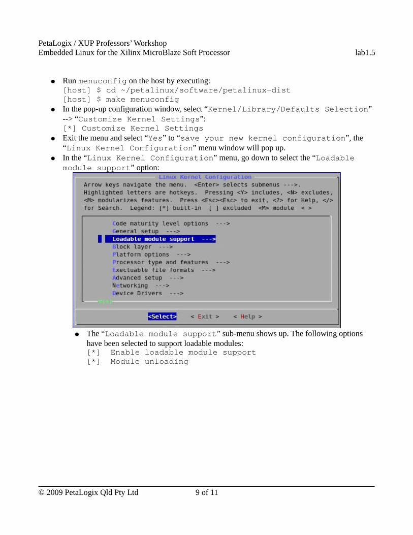
● In the “Linux Kernel Configuration” menu, go down to select the “Loadable module support” option:
● The “Loadable module support” sub-menu shows up. The following options have been selected to support loadable modules:[*] Enable loadable module support[*] Module unloading
© 2009 PetaLogix Qld Pty Ltd 9 of 11
PetaLogix / XUP Professors’ WorkshopEmbedded Linux for the Xilinx MicroBlaze Soft Processor lab1.5
● Exit without saving any changes. (No changes should be made to menuconfig. Just browse.)
Vendors/User Settings for Supporting Loadable Modules
insmod and rmmod are commands of busybox, let's see how to configure the busybox to support loading and unloading modules:
● Run menuconfig on the host by executing:[host] $ cd ~/petalinux/software/petalinux-dist[host] $ make menuconfig
● In the pop-up configuration window, select “Kernel/Library/Defaults Selection” --> “Customize Vendor/User Settings”:[*] Customize Vendor/User Settings
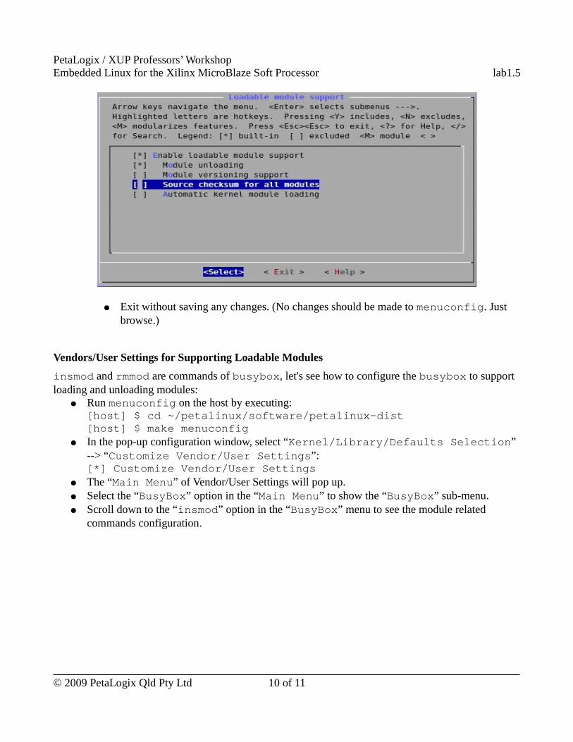
● The “Main Menu” of Vendor/User Settings will pop up.● Select the “BusyBox” option in the “Main Menu” to show the “BusyBox” sub-menu.● Scroll down to the “insmod” option in the “BusyBox” menu to see the module related
commands configuration.
© 2009 PetaLogix Qld Pty Ltd 10 of 11
PetaLogix / XUP Professors’ WorkshopEmbedded Linux for the Xilinx MicroBlaze Soft Processor lab1.5
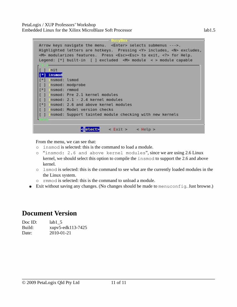
From the menu, we can see that:○ insmod is selected: this is the command to load a module.○ “insmod: 2.6 and above kernel modules”, since we are using 2.6 Linux
kernel, we should select this option to compile the insmod to support the 2.6 and above kernel.
○ lsmod is selected: this is the command to see what are the currently loaded modules in the the Linux system.
○ rmmod is selected: this is the command to unload a module.● Exit without saving any changes. (No changes should be made to menuconfig. Just browse.)
Document VersionDoc ID: lab1_5Build: xupv5-edk113-7425Date: 2010-01-21
© 2009 PetaLogix Qld Pty Ltd 11 of 11
XUP Professors’ WorkshopEmbedded Linux for the Xilinx MicroBlaze Soft Processor lab1.6
Lab 1.6 – MMU build and boot
RationaleMemory Management Unit (MMU) is a computer hardware component responsible for handling memory access. Its functions include translation of virtual address to physical address, memory protection and so on. If the processor is configured to have MMU and the Embedded Linux is configured to support MMU, memory management will protect processes from accessing the other's memory space; otherwise, all the processes including those in user space can access the whole memory.
Objectives● Build Embedded Linux with MMU support● Compare the system with MMU support and that without MMU support
IntroductionThe previous labs are all about uCLinux (Embedded Linux without MMU support). In this lab, we will build an Embedded Linux system with MMU support. We will then compare this system with uCLinux to see the effect of introducing MMU support.
TimeThis session will run for approximately 45 minutes.
PreparationIf this is the first lab you are doing then please refer to sections “Before You Start” of Lab 1.1 document for necessary preparatory information on how to setup the hardware environment.
© 2009 PetaLogix Qld Pty Ltd 1 of 9
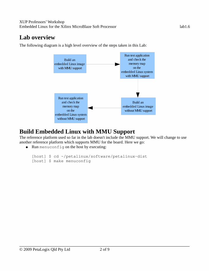
XUP Professors’ WorkshopEmbedded Linux for the Xilinx MicroBlaze Soft Processor lab1.6
Lab overviewThe following diagram is a high level overview of the steps taken in this Lab:
Build Embedded Linux with MMU SupportThe reference platform used so far in the lab doesn't include the MMU support. We will change to use another reference platform which supports MMU for the board. Here we go:
● Run menuconfig on the host by executing:
[host] $ cd ~/petalinux/software/petalinux-dist[host] $ make menuconfig
© 2009 PetaLogix Qld Pty Ltd 2 of 9
Build an embedded Linux image
with MMU support
Run test application and check the memory map
on the embedded Linux system
with MMU support
Build an embedded Linux image
without MMU support
Run test application and check the memory map
on the embedded Linux system
without MMU support
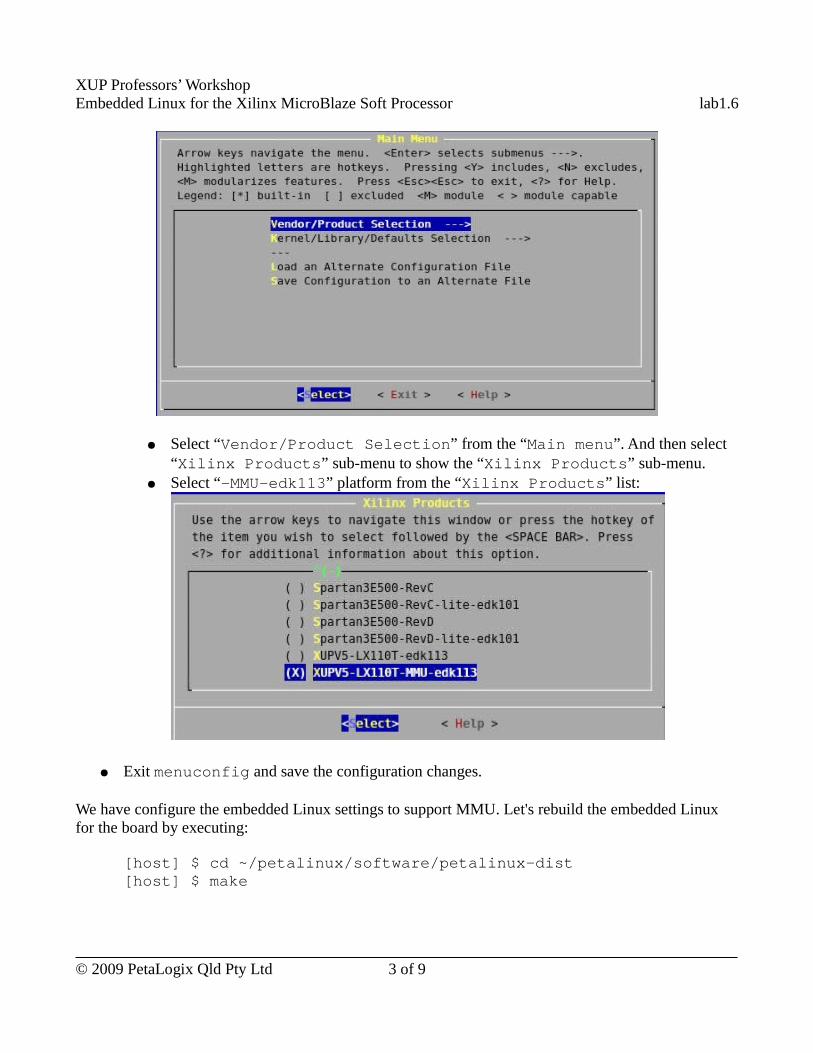
XUP Professors’ WorkshopEmbedded Linux for the Xilinx MicroBlaze Soft Processor lab1.6
● Select “Vendor/Product Selection” from the “Main menu”. And then select “Xilinx Products” sub-menu to show the “Xilinx Products” sub-menu.
● Select “-MMU-edk113” platform from the “Xilinx Products” list:
● Exit menuconfig and save the configuration changes.
We have configure the embedded Linux settings to support MMU. Let's rebuild the embedded Linux for the board by executing:
[host] $ cd ~/petalinux/software/petalinux-dist[host] $ make
© 2009 PetaLogix Qld Pty Ltd 3 of 9
XUP Professors’ WorkshopEmbedded Linux for the Xilinx MicroBlaze Soft Processor lab1.6
Create a User Application to Test MMUWhat's the difference between a Linux system supporting MMU and and the one not supporting MMU? Let's create a simple user application to check it. In the application, we will write some garbage to memory randomly. Here are the steps to create such an test application:
● Use PetaLinux tool to create a new user application by executing:
[host] $ petalinux-new-app memwalkThis command will create a memwalk directory containing source code template and Makefile in the ~/petalinux/software/user-apps directory.
● There is a complete application in ~/xup-materials/labs/lab1.6/resources/user-apps/memwalk; Please copy the files in that directory to the memwalk directory you have just created by executing (all in one line):
[host] $ cp ~/xup-materials/labs/lab1.6/resources/user-apps/memwalk/* ~/petalinux/software/user-apps/memwalk/
● Please take some time to look at the contents of memwalk.c file.
● Build the memwalk application and update the MicroBlaze Linux image by executing:
[host] $ cd ~/petalinux/software/user-apps/memwalk[host] $ make all image
Check the MMU EffectWhy is MMU useful? Let's check the MMU effect by running the memwalk program on both the MMU embedded Linux system and the non-MMU embedded Linux system.
Run Test Application on Embedded Linux with MMU Support
● Reboot the development board with the new embedded Linux image with MMU support using TFTP as we have learned in the “Booting the New Image” section in Lab 1.2.
● Run our test application memwalk after log into the MicroBlaze Linux system by executing the following command on the kermit console:
# memwalkThis application will write garbage to a randomly generated memory address. Here is the output on the kermit console after running the program:.SIGSEGV#
The application will be terminated and the system is still running. The MMU support protects the process from accessing memory which doesn't belong to it.
© 2009 PetaLogix Qld Pty Ltd 4 of 9
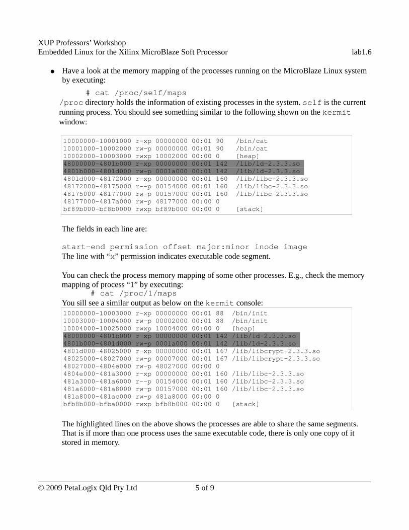
XUP Professors’ WorkshopEmbedded Linux for the Xilinx MicroBlaze Soft Processor lab1.6
● Have a look at the memory mapping of the processes running on the MicroBlaze Linux system by executing:
# cat /proc/self/maps/proc directory holds the information of existing processes in the system. self is the current running process. You should see something similar to the following shown on the kermit window:
10000000-10001000 r-xp 00000000 00:01 90 /bin/cat 10001000-10002000 rw-p 00000000 00:01 90 /bin/cat 10002000-10003000 rwxp 10002000 00:00 0 [heap] 48000000-4801b000 r-xp 00000000 00:01 142 /lib/ld-2.3.3.so 4801b000-4801d000 rw-p 0001a000 00:01 142 /lib/ld-2.3.3.so 4801d000-48172000 r-xp 00000000 00:01 160 /lib/libc-2.3.3.so 48172000-48175000 r--p 00154000 00:01 160 /lib/libc-2.3.3.so 48175000-48177000 rw-p 00157000 00:01 160 /lib/libc-2.3.3.so 48177000-4817a000 rw-p 48177000 00:00 0 bf89b000-bf8b0000 rwxp bf89b000 00:00 0 [stack]
The fields in each line are:
start-end permission offset major:minor inode imageThe line with “x” permission indicates executable code segment.
You can check the process memory mapping of some other processes. E.g., check the memory mapping of process “1” by executing:
# cat /proc/1/mapsYou sill see a similar output as below on the kermit console:10000000-10003000 r-xp 00000000 00:01 88 /bin/init 10003000-10004000 rw-p 00002000 00:01 88 /bin/init 10004000-10025000 rwxp 10004000 00:00 0 [heap] 48000000-4801b000 r-xp 00000000 00:01 142 /lib/ld-2.3.3.so 4801b000-4801d000 rw-p 0001a000 00:01 142 /lib/ld-2.3.3.so 4801d000-48025000 r-xp 00000000 00:01 167 /lib/libcrypt-2.3.3.so 48025000-48027000 rw-p 00007000 00:01 167 /lib/libcrypt-2.3.3.so 48027000-4804e000 rw-p 48027000 00:00 0 4804e000-481a3000 r-xp 00000000 00:01 160 /lib/libc-2.3.3.so 481a3000-481a6000 r--p 00154000 00:01 160 /lib/libc-2.3.3.so 481a6000-481a8000 rw-p 00157000 00:01 160 /lib/libc-2.3.3.so 481a8000-481ac000 rw-p 481a8000 00:00 0 bfb8b000-bfba0000 rwxp bfb8b000 00:00 0 [stack]
The highlighted lines on the above shows the processes are able to share the same segments. That is if more than one process uses the same executable code, there is only one copy of it stored in memory.
© 2009 PetaLogix Qld Pty Ltd 5 of 9
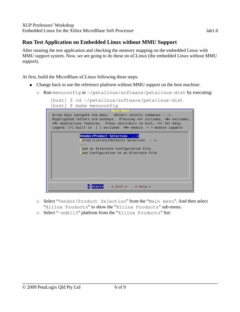
XUP Professors’ WorkshopEmbedded Linux for the Xilinx MicroBlaze Soft Processor lab1.6
Run Test Application on Embedded Linux without MMU Support
After running the test application and checking the memory mapping on the embedded Linux with MMU support system. Now, we are going to do these on uCLinux (the embedded Linux without MMU support).
At first, build the MicroBlaze uCLinux following these steps:
● Change back to use the reference platform without MMU support on the host machine:
○ Run menuconfig in ~/petalinux/software/petalinux-dist by executing:
[host] $ cd ~/petalinux/software/petalinux-dist[host] $ make menuconfig
○ Select “Vendor/Product Selection” from the “Main menu”. And then select “Xilinx Products” to show the “Xilinx Products” sub-menu.
○ Select “-edk113” platform from the “Xilinx Products” list:
© 2009 PetaLogix Qld Pty Ltd 6 of 9
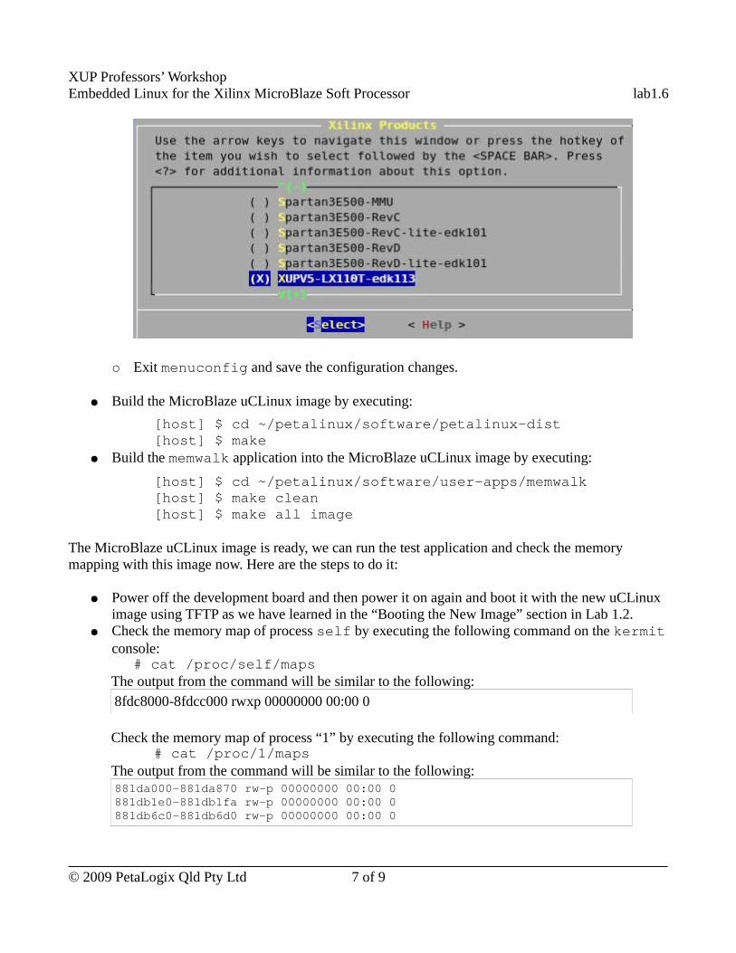
XUP Professors’ WorkshopEmbedded Linux for the Xilinx MicroBlaze Soft Processor lab1.6
○ Exit menuconfig and save the configuration changes.
● Build the MicroBlaze uCLinux image by executing:
[host] $ cd ~/petalinux/software/petalinux-dist[host] $ make
● Build the memwalk application into the MicroBlaze uCLinux image by executing:
[host] $ cd ~/petalinux/software/user-apps/memwalk[host] $ make clean[host] $ make all image
The MicroBlaze uCLinux image is ready, we can run the test application and check the memory mapping with this image now. Here are the steps to do it:
● Power off the development board and then power it on again and boot it with the new uCLinux image using TFTP as we have learned in the “Booting the New Image” section in Lab 1.2.
● Check the memory map of process self by executing the following command on the kermit console:
# cat /proc/self/mapsThe output from the command will be similar to the following:8fdc8000-8fdcc000 rwxp 00000000 00:00 0
Check the memory map of process “1” by executing the following command:# cat /proc/1/maps
The output from the command will be similar to the following:881da000-881da870 rw-p 00000000 00:00 0 881db1e0-881db1fa rw-p 00000000 00:00 0 881db6c0-881db6d0 rw-p 00000000 00:00 0
© 2009 PetaLogix Qld Pty Ltd 7 of 9
XUP Professors’ WorkshopEmbedded Linux for the Xilinx MicroBlaze Soft Processor lab1.6
881dbec0-881dbecc rw-p 00000000 00:00 0 881dbf80-881dbf88 rw-p 00000000 00:00 0 881dbfc0-881dbfda rw-p 00000000 00:00 0 884af698-884af6c1 rw-p 00000000 00:00 0 884af6d8-884af701 rw-p 00000000 00:00 0 884af718-884af73f rw-p 00000000 00:00 0 884af758-884af77f rw-p 00000000 00:00 0 884e0000-88500000 rwxp 00000000 00:00 0
Check the memory mapping of the other processes. The output will be similar to the above. For every process, all its executable code is kept in the one segment. No sharable executable code will be in a system without MMU support.
● Run our memwalk application by executing:# memwalk
The system hangs after the program printing some dots:
...........................................................
The system crashes because every process can access the whole memory if the Linux system has no MMU support.
Use Completed ResourceThe completed Linux image for this lab is available in ~/xup_materials/labs/lab1.6/completed/. If you are stuck in any problem in the lab, you are welcome to use the completed resource. Here is the instructions on how to use the completed resource:
● Copy the completed user applications to PetaLinux tree and the Linux images to /tftpboot directory by executing the following command on the host:
[host] $ ~/xup_materials/complete_lab 1.6
The Linux image with MMU support is ~/tftpboot/image.ub.
The Linux image without MMU support is ~/tftpboot/image.ub.nommu
● Hit any key to stop auto boot when you see
Hit any key to stop autoboot: 5
on the kermit console.
● Boot the board with Linux image with MMU support using tftp by executing the following command on the kermit console:
U-Boot> tftp $(netstart) image.ub; bootm
© 2009 PetaLogix Qld Pty Ltd 8 of 9
XUP Professors’ WorkshopEmbedded Linux for the Xilinx MicroBlaze Soft Processor lab1.6
● Boot the board with Linux image without MMU support using tftp by executing the following command on the kermit console:
U-Boot> tftp $(netstart) image.ub.nommu; bootm
OutcomesAt the completion of this lab you should
● know how to configure the system with MMU support● understand some important differences between MicroBlaze Linux systems configure with and
without hardware MMU support.
Document VersionDoc ID: lab1_6Build: xupv5-edk113-7425Date: 2010-01-21
© 2009 PetaLogix Qld Pty Ltd 9 of 9
XUP Professors’ WorkshopEmbedded Linux for the Xilinx MicroBlaze Soft Processor lab2.1
Lab 2.1 – Base System Builder and Board Bring up
RationaleThe real power of Linux on an FPGA platform comes when the custom logic resources of the FPGA are combined with the usability and software infrastructure of the operating system. Xilinx provides a powerful tool to ease FPGA design. The purpose of this lab session is to go through the Xilinx Base System Builder (BSB) and learn how to use PetaLogix tools to configure Embedded Linux system for a new platform.
Objectives● Use BSB and EDK to create a simple Linux-capable design● Use PetaLinux to create a new Embedded Linux target for the hardware platform● Build and boot the new Embedded Linux system
IntroductionIn previous labs, we have learned how to configure and build Embedded Linux systems. Embedded Linux always runs on a certain hardware platform. In this lab session, you will create a Linux capable FPGA platform from scratch.
TimeThis session will run for approximately 70 minutes.
PreparationIf this is the first lab you are doing then please refer to sections “Before You Start” of Lab 1.1 document for necessary preparatory information on how to setup the hardware environment.
© 2009 PetaLogix Qld Pty Ltd 1 of 29
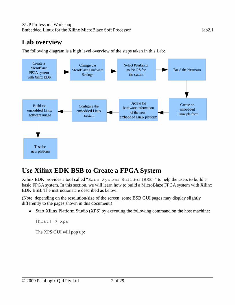
XUP Professors’ WorkshopEmbedded Linux for the Xilinx MicroBlaze Soft Processor lab2.1
Lab overviewThe following diagram is a high level overview of the steps taken in this Lab:
Use Xilinx EDK BSB to Create a FPGA SystemXilinx EDK provides a tool called “Base System Builder(BSB)” to help the users to build a basic FPGA system. In this section, we will learn how to build a MicroBlaze FPGA system with Xilinx EDK BSB. The instructions are described as below:
(Note: depending on the resolution/size of the screen, some BSB GUI pages may display slightly differently to the pages shown in this document.)
● Start Xilinx Platform Studio (XPS) by executing the following command on the host machine:
[host] $ xps
The XPS GUI will pop up:
© 2009 PetaLogix Qld Pty Ltd 2 of 29
Create a MicroBlaze
FPGA system with Xilinx EDK
Change the MicroBlaze Hardware
Settings
Select PetaLinux as the OS for
the systemBuild the bitstream
Create an embedded
Linux platform
Update the hardware information
of the new embedded Linux platform
Configure the embedded Linux
system
Build the embedded Linux software image
Test the new platform
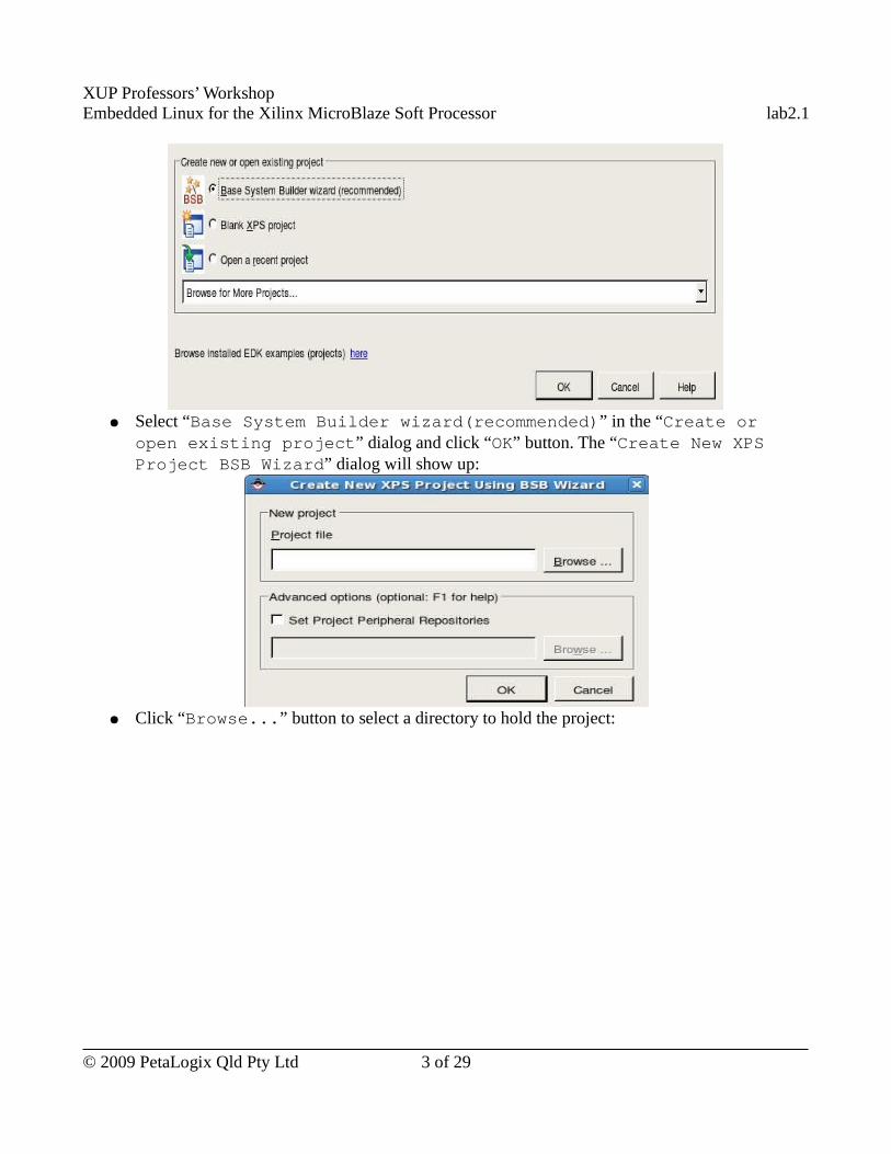
XUP Professors’ WorkshopEmbedded Linux for the Xilinx MicroBlaze Soft Processor lab2.1
● Select “Base System Builder wizard(recommended)” in the “Create or open existing project” dialog and click “OK” button. The “Create New XPS Project BSB Wizard” dialog will show up:
● Click “Browse...” button to select a directory to hold the project:
© 2009 PetaLogix Qld Pty Ltd 3 of 29
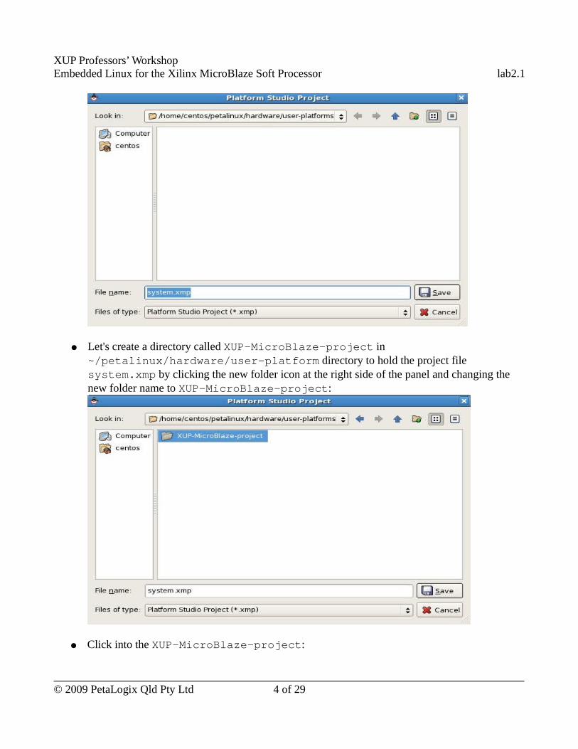
XUP Professors’ WorkshopEmbedded Linux for the Xilinx MicroBlaze Soft Processor lab2.1
● Let's create a directory called XUP-MicroBlaze-project in ~/petalinux/hardware/user-platform directory to hold the project file system.xmp by clicking the new folder icon at the right side of the panel and changing the new folder name to XUP-MicroBlaze-project:
● Click into the XUP-MicroBlaze-project:
© 2009 PetaLogix Qld Pty Ltd 4 of 29
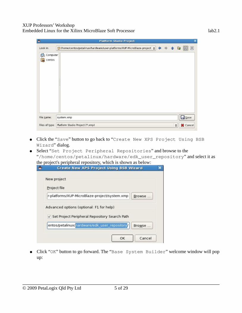
XUP Professors’ WorkshopEmbedded Linux for the Xilinx MicroBlaze Soft Processor lab2.1
● Click the “Save” button to go back to “Create New XPS Project Using BSB Wizard” dialog.
● Select “Set Project Peripheral Repositories” and browse to the “/home/centos/petalinux/hardware/edk_user_repository” and select it as the project's peripheral repository, which is shown as below:
● Click “OK” button to go forward. The “Base System Builder” welcome window will pop up:
© 2009 PetaLogix Qld Pty Ltd 5 of 29
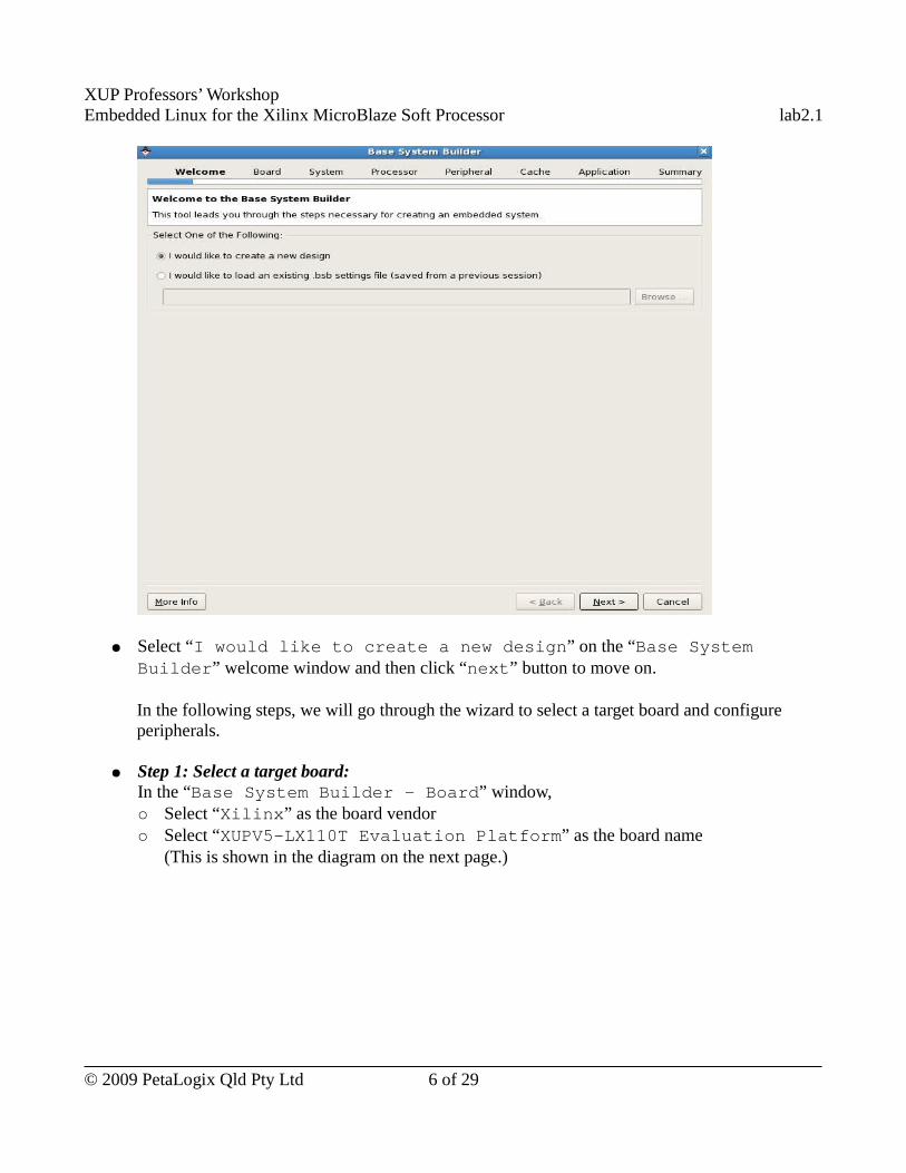
XUP Professors’ WorkshopEmbedded Linux for the Xilinx MicroBlaze Soft Processor lab2.1
● Select “I would like to create a new design” on the “Base System Builder” welcome window and then click “next” button to move on.
In the following steps, we will go through the wizard to select a target board and configure peripherals.
● Step 1: Select a target board:In the “Base System Builder - Board” window, ○ Select “Xilinx” as the board vendor ○ Select “XUPV5-LX110T Evaluation Platform” as the board name
(This is shown in the diagram on the next page.)
© 2009 PetaLogix Qld Pty Ltd 6 of 29
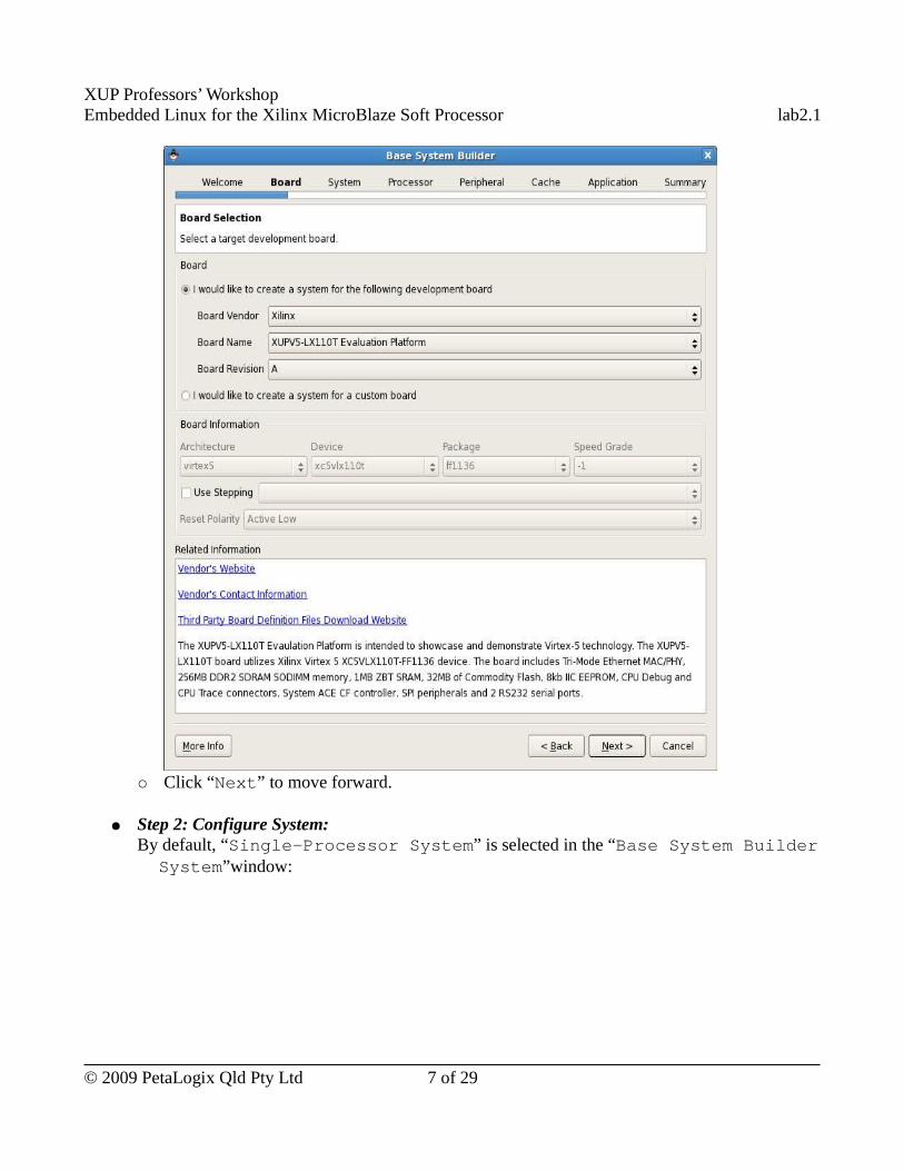
XUP Professors’ WorkshopEmbedded Linux for the Xilinx MicroBlaze Soft Processor lab2.1
○ Click “Next” to move forward.
● Step 2: Configure System:By default, “Single-Processor System” is selected in the “Base System Builder � System”window:
© 2009 PetaLogix Qld Pty Ltd 7 of 29
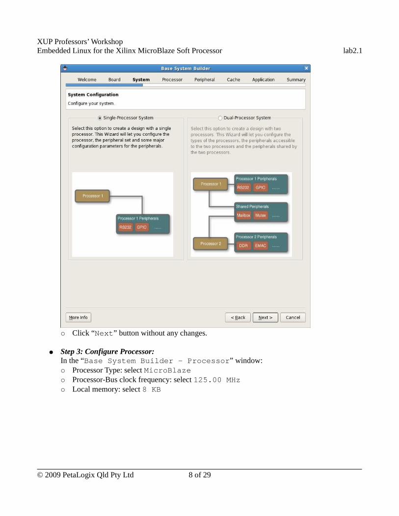
XUP Professors’ WorkshopEmbedded Linux for the Xilinx MicroBlaze Soft Processor lab2.1
○ Click “Next” button without any changes.
● Step 3: Configure Processor:In the “Base System Builder - Processor” window:○ Processor Type: select MicroBlaze○ Processor-Bus clock frequency: select 125.00 MHz○ Local memory: select 8 KB
© 2009 PetaLogix Qld Pty Ltd 8 of 29
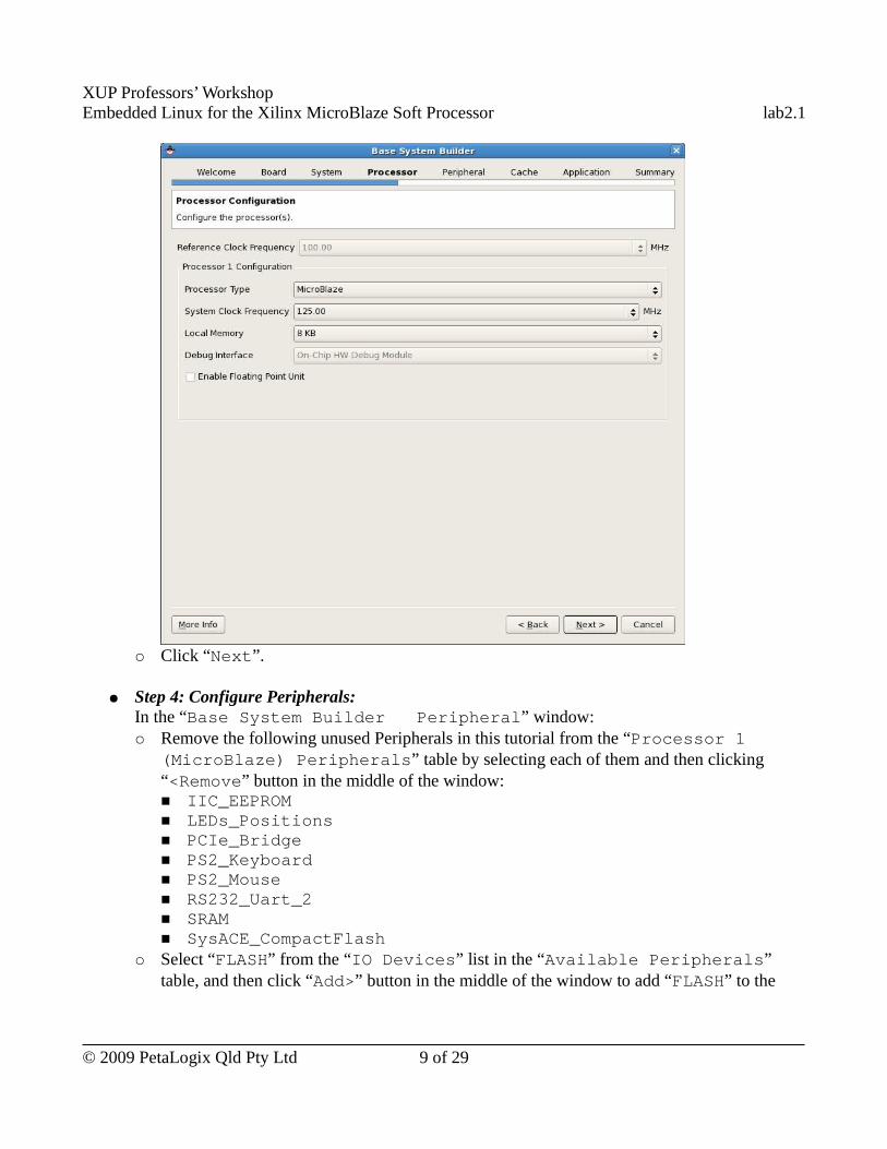
XUP Professors’ WorkshopEmbedded Linux for the Xilinx MicroBlaze Soft Processor lab2.1
○ Click “Next”.
● Step 4: Configure Peripherals:In the “Base System Builder � Peripheral” window:○ Remove the following unused Peripherals in this tutorial from the “Processor 1
(MicroBlaze) Peripherals” table by selecting each of them and then clicking “<Remove” button in the middle of the window:■ IIC_EEPROM■ LEDs_Positions■ PCIe_Bridge■ PS2_Keyboard■ PS2_Mouse■ RS232_Uart_2■ SRAM■ SysACE_CompactFlash
○ Select “FLASH” from the “IO Devices” list in the “Available Peripherals” table, and then click “Add>” button in the middle of the window to add “FLASH” to the
© 2009 PetaLogix Qld Pty Ltd 9 of 29
XUP Professors’ WorkshopEmbedded Linux for the Xilinx MicroBlaze Soft Processor lab2.1
processor's peripherals. Now, you should see “FLASH” listed in the “Processor 1 (MicroBlaze) Peripherals” table.
○ Click “Select All” button which is just above the peripheral list on the right of the window. This operation will select all the peripherals and expand their settings.
○ Change “Hard_Ethernet_MAC” settings:■ Tick “Use DMA” and “Use Interrupt”
○ Change “RS232_UART_1” settings:■ Baud Rate: Select 115200■ Tick “Use Interrupt”
○ Because Linux relies on timer ticks and the timer is not configured by default, we add a timer peripheral by following these steps: ■ Click “xps_timer” on the “Internal Peripherals” list on the “Available
Peripherals” list to select it.■ Click “Add>” button in the middle of the window to add a timer to the peripherals list
on the right of the window. The xps_timer_0 is automatically selected when it is added.
■ Tick “Use Interrupt” of timer “xps_timer_0”The Peripherals settings are shown in the diagram on the next page (Please make sure your peripheral settings are the same as those in the following diagram
© 2009 PetaLogix Qld Pty Ltd 10 of 29
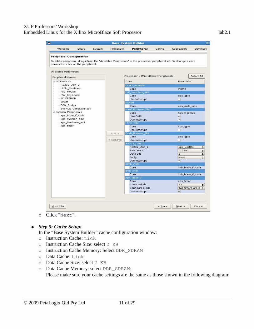
XUP Professors’ WorkshopEmbedded Linux for the Xilinx MicroBlaze Soft Processor lab2.1
○ Click “Next”.
● Step 5: Cache Setup:In the “Base System Builder” cache configuration window:○ Instruction Cache: tick○ Instruction Cache Size: select 2 KB○ Instruction Cache Memory: Select DDR_SDRAM○ Data Cache: tick○ Data Cache Size: select 2 KB○ Data Cache Memory: select DDR_SDRAM:
Please make sure your cache settings are the same as those shown in the following diagram:
© 2009 PetaLogix Qld Pty Ltd 11 of 29
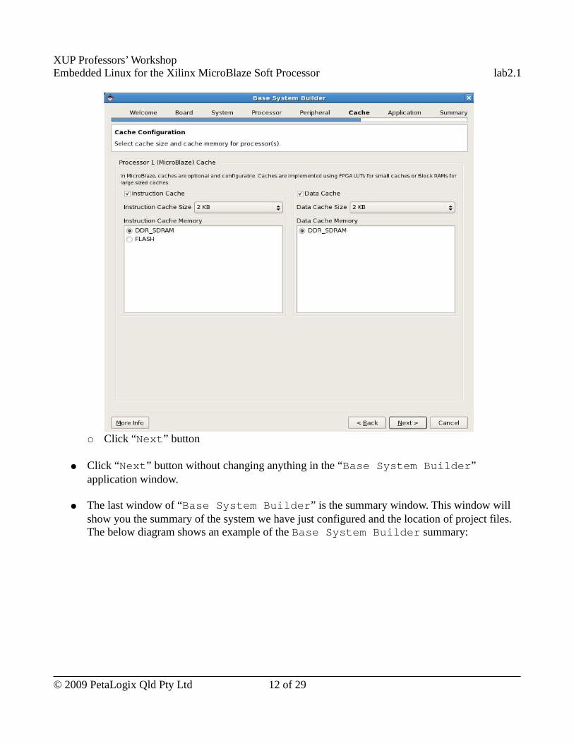
XUP Professors’ WorkshopEmbedded Linux for the Xilinx MicroBlaze Soft Processor lab2.1
○ Click “Next” button
● Click “Next” button without changing anything in the “Base System Builder” application window.
● The last window of “Base System Builder” is the summary window. This window will show you the summary of the system we have just configured and the location of project files. The below diagram shows an example of the Base System Builder summary:
© 2009 PetaLogix Qld Pty Ltd 12 of 29
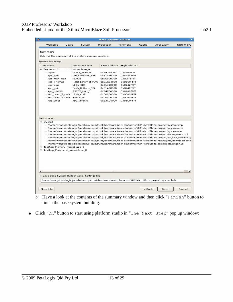
XUP Professors’ WorkshopEmbedded Linux for the Xilinx MicroBlaze Soft Processor lab2.1
○ Have a look at the contents of the summary window and then click “Finish” button to finish the base system building.
● Click “OK” button to start using platform studio in “The Next Step” pop up window:
© 2009 PetaLogix Qld Pty Ltd 13 of 29
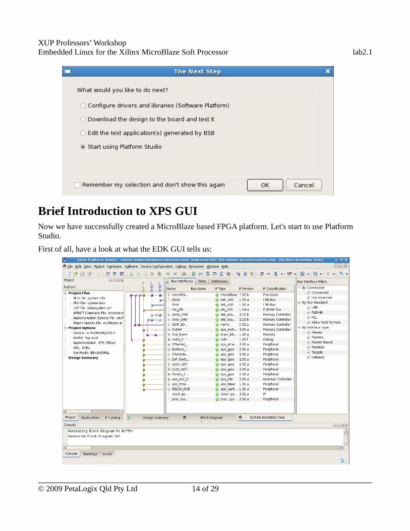
XUP Professors’ WorkshopEmbedded Linux for the Xilinx MicroBlaze Soft Processor lab2.1
Brief Introduction to XPS GUINow we have successfully created a MicroBlaze based FPGA platform. Let's start to use Platform Studio.
First of all, have a look at what the EDK GUI tells us:
© 2009 PetaLogix Qld Pty Ltd 14 of 29
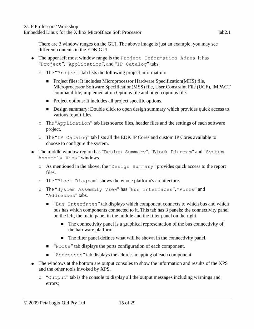
XUP Professors’ WorkshopEmbedded Linux for the Xilinx MicroBlaze Soft Processor lab2.1
There are 3 window ranges on the GUI. The above image is just an example, you may see different contents in the EDK GUI.
● The upper left most window range is the Project Information Adrea. It has “Project”, “Application”, and “IP Catalog” tabs.
○ The “Project” tab lists the following project information:
■ Project files: It includes Microprocessor Hardware Specification(MHS) file, Microprocessor Software Specification(MSS) file, User Constraint File (UCF), iMPACT command file, implementation Options file and bitgen options file.
■ Project options: It includes all project specific options.
■ Design summary: Double click to open design summary which provides quick access to various report files.
○ The “Application” tab lists source files, header files and the settings of each software project.
○ The “IP Catalog” tab lists all the EDK IP Cores and custom IP Cores available to choose to configure the system.
● The middle window region has “Design Summary”, “Block Diagram” and “System Assembly View” windows.
○ As mentioned in the above, the “Design Summary” provides quick access to the report files.
○ The “Block Diagram” shows the whole platform's architecture.
○ The “System Assembly View” has “Bus Interfaces”, “Ports” and “Addresses” tabs.
■ “Bus Interfaces” tab displays which component connects to which bus and which bus has which components connected to it. This tab has 3 panels: the connectivity panel on the left, the main panel in the middle and the filter panel on the right.
■ The connectivity panel is a graphical representation of the bus connectivity of the hardware platform.
■ The filter panel defines what will be shown in the connectivity panel.
■ “Ports” tab displays the ports configuration of each component.
■ “Addresses” tab displays the address mapping of each component.
● The windows at the bottom are output consoles to show the information and results of the XPS and the other tools invoked by XPS.
○ “Output” tab is the console to display all the output messages including warnings and errors;
© 2009 PetaLogix Qld Pty Ltd 15 of 29
XUP Professors’ WorkshopEmbedded Linux for the Xilinx MicroBlaze Soft Processor lab2.1
○ “Warning” tab is the console to display the warning messages;
○ “Error” tab is the console to display the error messages.
Major Project Files IntroductionAs mentioned previously in this lab, BSB generates a complete hardware system. The hardware system is described by the following files:
● system.mhs – Microprocessor Hardware Specification file. This file describes the hardware structure of the system. It describes the bus connection, ports connection, address mappings and other configuration settings of each of the cores in the system. If you add or delete a Core or change its configuration through the GUI, this file will be changed too(and vice versa).
● system.mss – Microprocessor Software Specification file. This file describes the software settings about OS and drivers of the system but not applications.
The PetaLinux tools read the system.mss file to know what cores are used in the system.
● data/system.ucf – User constraint file. Describes IO standard constraints, location constraints, timing constraints and etc.
● system.xmp – XPS project file. This file describes project options of the system and the software applications settings.
Configure the MicroBlaze to Enable Barrel ShifterSo far, we have configured a basic MicroBlaze FPGA system. In this section we will change the MicroBlaze hardware settings to enable Barrel Shifter to learn how to change the settings of a hardware core using XPS.
At first, let's have a general idea on Barrel shifter. A Barrel shifter can shift a data word by a specified number of bits in one clock cycle. Including Barrel shifter will dramatically improve the performance but will increase the size of the processor.
Now, we will change the MicroBlaze configuration to include Barrel Shifter on XPS GUI and see the change done by XPS automatically to system.mhs file.
We can change system through “System Assembly View” or modify the system.mhs file directly.
● Before we do any changes, have a look at the MicroBlaze settings in the system.mhs file. Open the system.mhs file by double clicking the system.mhs item from “Project” tab. And then read the settings of microblaze component. Here is the MicroBlaze settings defined in the system.mhs file:
BEGIN microblaze
© 2009 PetaLogix Qld Pty Ltd 16 of 29
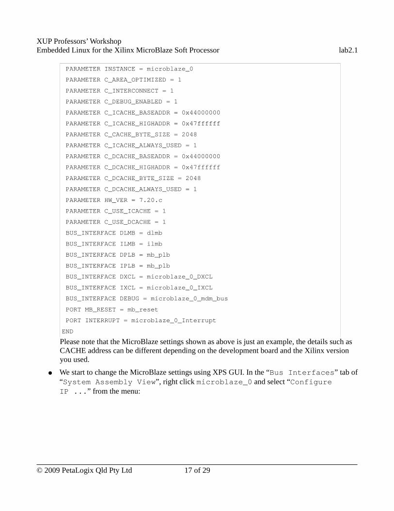
XUP Professors’ WorkshopEmbedded Linux for the Xilinx MicroBlaze Soft Processor lab2.1
PARAMETER INSTANCE = microblaze_0
PARAMETER C_AREA_OPTIMIZED = 1
PARAMETER C_INTERCONNECT = 1
PARAMETER C_DEBUG_ENABLED = 1
PARAMETER C_ICACHE_BASEADDR = 0x44000000
PARAMETER C_ICACHE_HIGHADDR = 0x47ffffff
PARAMETER C_CACHE_BYTE_SIZE = 2048
PARAMETER C_ICACHE_ALWAYS_USED = 1
PARAMETER C_DCACHE_BASEADDR = 0x44000000
PARAMETER C_DCACHE_HIGHADDR = 0x47ffffff
PARAMETER C_DCACHE_BYTE_SIZE = 2048
PARAMETER C_DCACHE_ALWAYS_USED = 1
PARAMETER HW_VER = 7.20.c
PARAMETER C_USE_ICACHE = 1
PARAMETER C_USE_DCACHE = 1
BUS_INTERFACE DLMB = dlmb
BUS_INTERFACE ILMB = ilmb
BUS_INTERFACE DPLB = mb_plb
BUS_INTERFACE IPLB = mb_plb
BUS_INTERFACE DXCL = microblaze_0_DXCL
BUS_INTERFACE IXCL = microblaze_0_IXCL
BUS_INTERFACE DEBUG = microblaze_0_mdm_bus
PORT MB_RESET = mb_reset
PORT INTERRUPT = microblaze_0_Interrupt
END
Please note that the MicroBlaze settings shown as above is just an example, the details such as CACHE address can be different depending on the development board and the Xilinx version you used.
● We start to change the MicroBlaze settings using XPS GUI. In the “Bus Interfaces” tab of “System Assembly View”, right click microblaze_0 and select “Configure IP ...” from the menu:
© 2009 PetaLogix Qld Pty Ltd 17 of 29
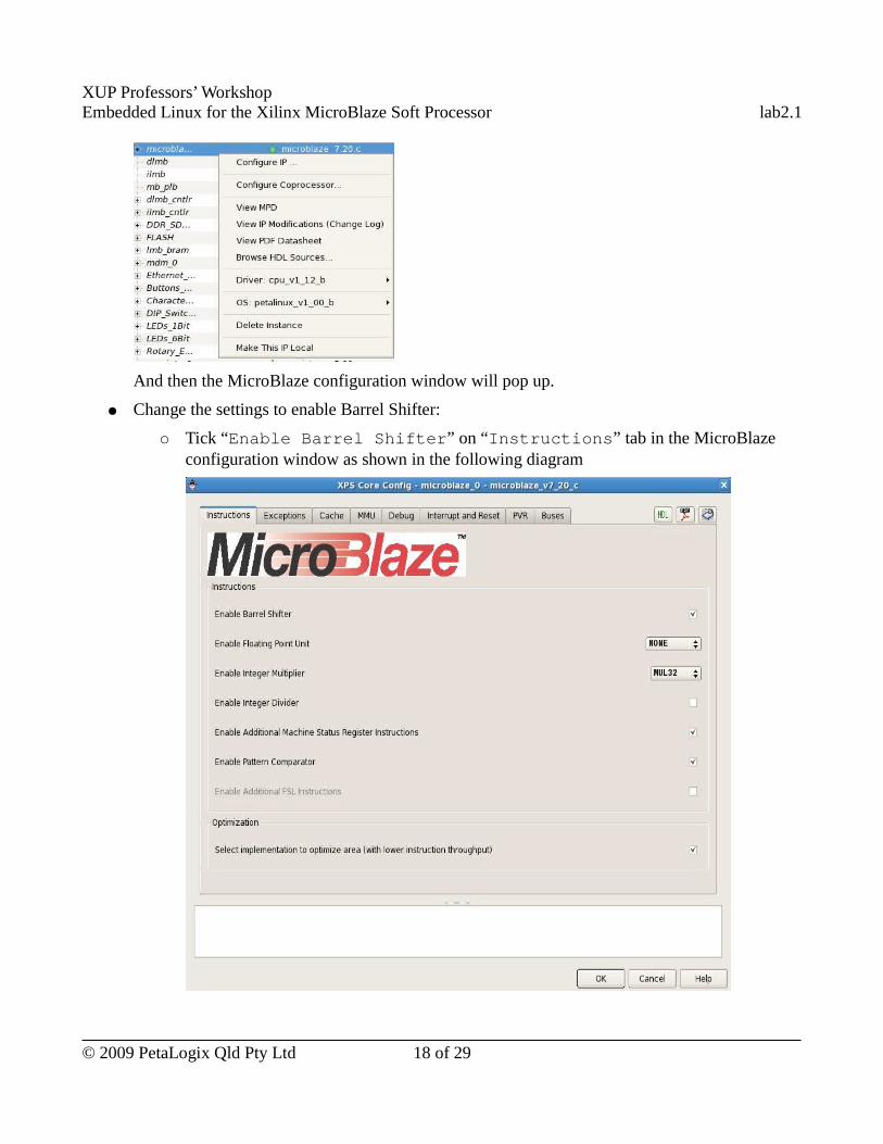
XUP Professors’ WorkshopEmbedded Linux for the Xilinx MicroBlaze Soft Processor lab2.1
And then the MicroBlaze configuration window will pop up.
● Change the settings to enable Barrel Shifter:
○ Tick “Enable Barrel Shifter” on “Instructions” tab in the MicroBlaze configuration window as shown in the following diagram
© 2009 PetaLogix Qld Pty Ltd 18 of 29
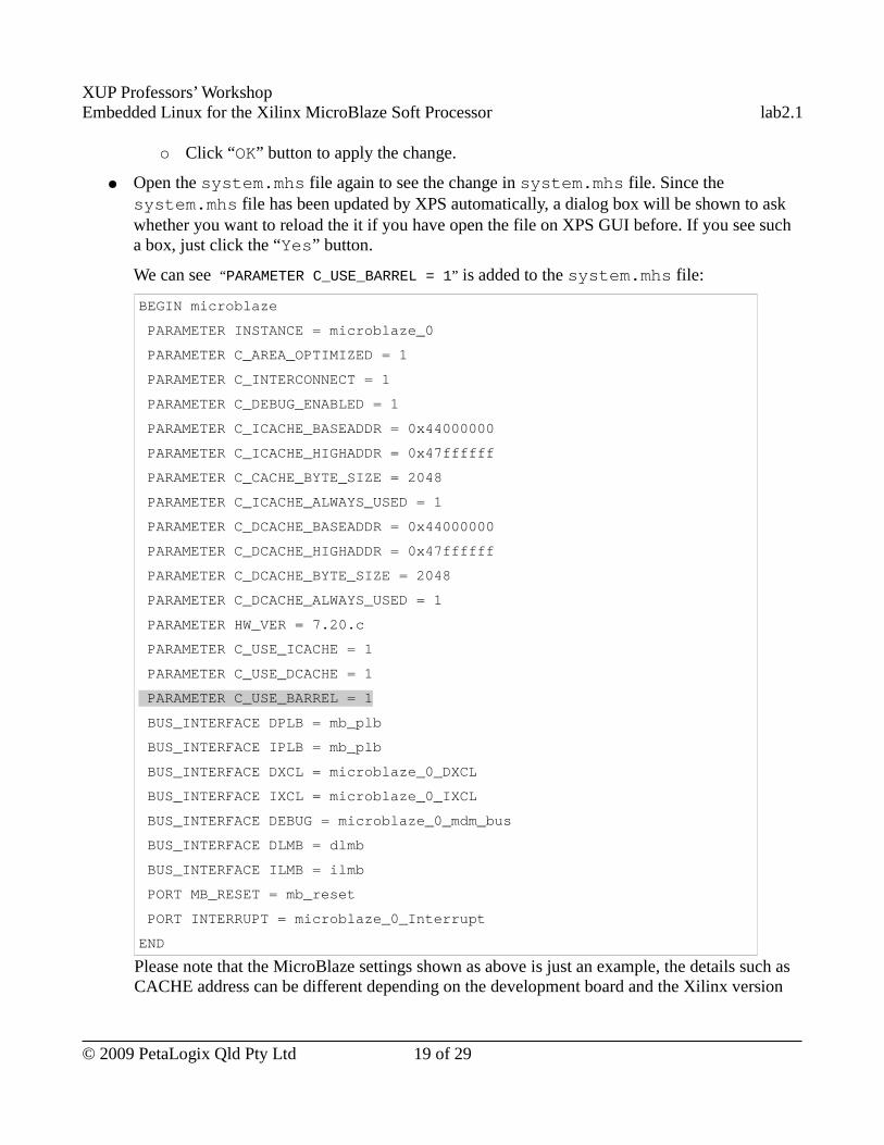
XUP Professors’ WorkshopEmbedded Linux for the Xilinx MicroBlaze Soft Processor lab2.1
○ Click “OK” button to apply the change.
● Open the system.mhs file again to see the change in system.mhs file. Since the system.mhs file has been updated by XPS automatically, a dialog box will be shown to ask whether you want to reload the it if you have open the file on XPS GUI before. If you see such a box, just click the “Yes” button.
We can see “PARAMETER C_USE_BARREL = 1” is added to the system.mhs file:
BEGIN microblaze
PARAMETER INSTANCE = microblaze_0
PARAMETER C_AREA_OPTIMIZED = 1
PARAMETER C_INTERCONNECT = 1
PARAMETER C_DEBUG_ENABLED = 1
PARAMETER C_ICACHE_BASEADDR = 0x44000000
PARAMETER C_ICACHE_HIGHADDR = 0x47ffffff
PARAMETER C_CACHE_BYTE_SIZE = 2048
PARAMETER C_ICACHE_ALWAYS_USED = 1
PARAMETER C_DCACHE_BASEADDR = 0x44000000
PARAMETER C_DCACHE_HIGHADDR = 0x47ffffff
PARAMETER C_DCACHE_BYTE_SIZE = 2048
PARAMETER C_DCACHE_ALWAYS_USED = 1
PARAMETER HW_VER = 7.20.c
PARAMETER C_USE_ICACHE = 1
PARAMETER C_USE_DCACHE = 1
PARAMETER C_USE_BARREL = 1
BUS_INTERFACE DPLB = mb_plb
BUS_INTERFACE IPLB = mb_plb
BUS_INTERFACE DXCL = microblaze_0_DXCL
BUS_INTERFACE IXCL = microblaze_0_IXCL
BUS_INTERFACE DEBUG = microblaze_0_mdm_bus
BUS_INTERFACE DLMB = dlmb
BUS_INTERFACE ILMB = ilmb
PORT MB_RESET = mb_reset
PORT INTERRUPT = microblaze_0_Interrupt
END
Please note that the MicroBlaze settings shown as above is just an example, the details such as CACHE address can be different depending on the development board and the Xilinx version
© 2009 PetaLogix Qld Pty Ltd 19 of 29
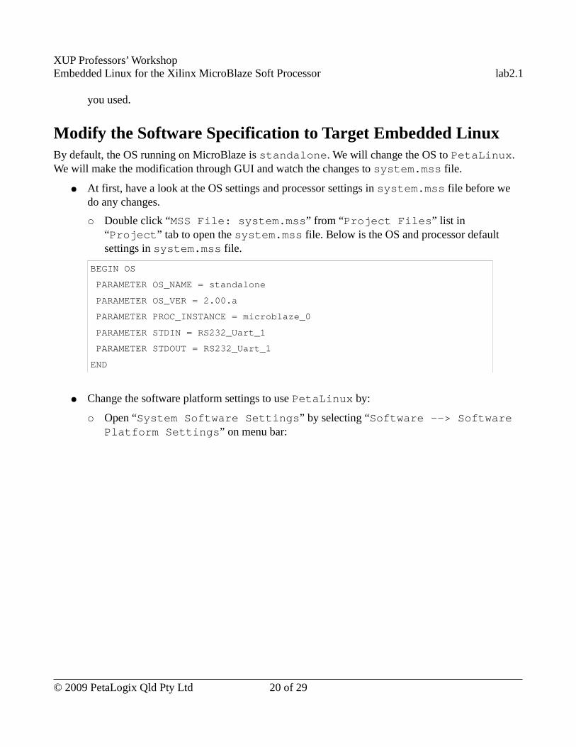
XUP Professors’ WorkshopEmbedded Linux for the Xilinx MicroBlaze Soft Processor lab2.1
you used.
Modify the Software Specification to Target Embedded LinuxBy default, the OS running on MicroBlaze is standalone. We will change the OS to PetaLinux. We will make the modification through GUI and watch the changes to system.mss file.
● At first, have a look at the OS settings and processor settings in system.mss file before we do any changes.
○ Double click “MSS File: system.mss” from “Project Files” list in “Project” tab to open the system.mss file. Below is the OS and processor default settings in system.mss file.
BEGIN OS
PARAMETER OS_NAME = standalone
PARAMETER OS_VER = 2.00.a
PARAMETER PROC_INSTANCE = microblaze_0
PARAMETER STDIN = RS232_Uart_1
PARAMETER STDOUT = RS232_Uart_1
END
● Change the software platform settings to use PetaLinux by:
○ Open “System Software Settings” by selecting “Software --> Software Platform Settings” on menu bar:
© 2009 PetaLogix Qld Pty Ltd 20 of 29
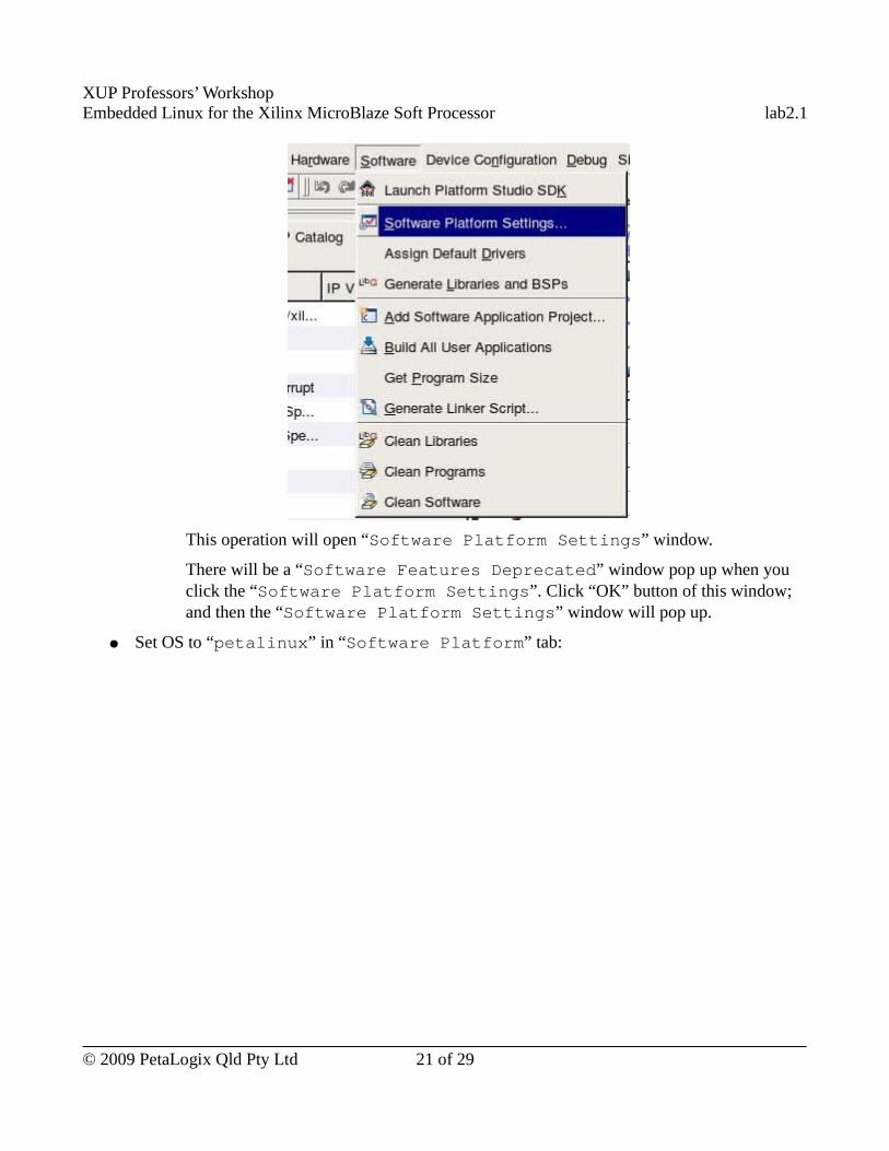
XUP Professors’ WorkshopEmbedded Linux for the Xilinx MicroBlaze Soft Processor lab2.1
This operation will open “Software Platform Settings” window.
There will be a “Software Features Deprecated” window pop up when you click the “Software Platform Settings”. Click “OK” button of this window; and then the “Software Platform Settings” window will pop up.
● Set OS to “petalinux” in “Software Platform” tab:
© 2009 PetaLogix Qld Pty Ltd 21 of 29
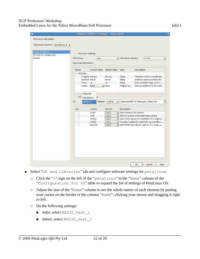
XUP Professors’ WorkshopEmbedded Linux for the Xilinx MicroBlaze Soft Processor lab2.1
● Select “OS and Libraries” tab and configure software settings for petalinux:
○ Click the “+” sign on the left of the “petalinux” in the “Name” column of the “Configuration for OS” table to expand the list of settings of PetaLinux OS.
○ Adjust the size of the “Name” column to see the whole names of each element by putting your cursor on the border of the column “Name”, clicking your mouse and dragging it right or left.
○ Do the following settings:
■ stdin: select RS232_Uart_1
■ stdout: select RS232_Uart_1
© 2009 PetaLogix Qld Pty Ltd 22 of 29
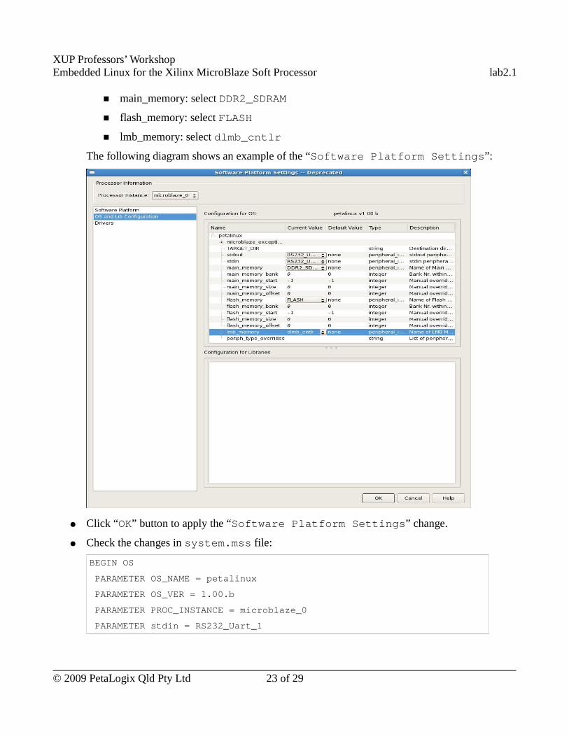
XUP Professors’ WorkshopEmbedded Linux for the Xilinx MicroBlaze Soft Processor lab2.1
■ main_memory: select DDR2_SDRAM
■ flash_memory: select FLASH
■ lmb_memory: select dlmb_cntlr
The following diagram shows an example of the “Software Platform Settings”:
● Click “OK” button to apply the “Software Platform Settings” change.
● Check the changes in system.mss file:
BEGIN OS
PARAMETER OS_NAME = petalinux
PARAMETER OS_VER = 1.00.b
PARAMETER PROC_INSTANCE = microblaze_0
PARAMETER stdin = RS232_Uart_1
© 2009 PetaLogix Qld Pty Ltd 23 of 29
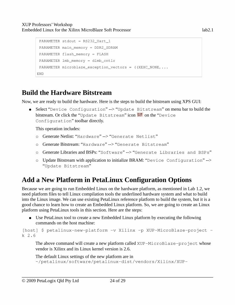
XUP Professors’ WorkshopEmbedded Linux for the Xilinx MicroBlaze Soft Processor lab2.1
PARAMETER stdout = RS232_Uart_1
PARAMETER main_memory = DDR2_SDRAM
PARAMETER flash_memory = FLASH
PARAMETER lmb_memory = dlmb_cntlr
PARAMETER microblaze_exception_vectors = ((XEXC_NONE,...
END
Build the Hardware BitstreamNow, we are ready to build the hardware. Here is the steps to build the bitstream using XPS GUI:
● Select “Device Configuration” --> “Update Bitstream” on menu bar to build the bitstream. Or click the “Update Bitstream” icon on the “Device Configuration” toolbar directly.
This operation includes:
○ Generate Netlist: “Hardware” --> “Generate Netlist”
○ Generate Bitstream: “Hardware” --> “Generate Bitstream”
○ Generate Libraries and BSPs: “Software” --> “Generate Libraries and BSPs”
○ Update Bitstream with application to initialize BRAM: “Device Configuration” --> “Update Bitstream”
Add a New Platform in PetaLinux Configuration OptionsBecause we are going to run Embedded Linux on the hardware platform, as mentioned in Lab 1.2, we need platform files to tell Linux compilation tools the underlined hardware system and what to build into the Linux image. We can use existing PetaLinux reference platform to build the system, but it is a good chance to learn how to create an Embedded Linux platform. So, we are going to create an Linux platform using PetaLinux tools in this section. Here are the steps:
● Use PetaLinux tool to create a new Embedded Linux platform by executing the following commands on the host machine:
[host] $ petalinux-new-platform -v Xilinx -p XUP-MicroBlaze-project -k 2.6
The above command will create a new platform called XUP-MicroBlaze-project whose vendor is Xilinx and its Linux kernel version is 2.6.
The default Linux settings of the new platform are in ~/petalinux/software/petalinux-dist/vendors/Xilinx/XUP-
© 2009 PetaLogix Qld Pty Ltd 24 of 29
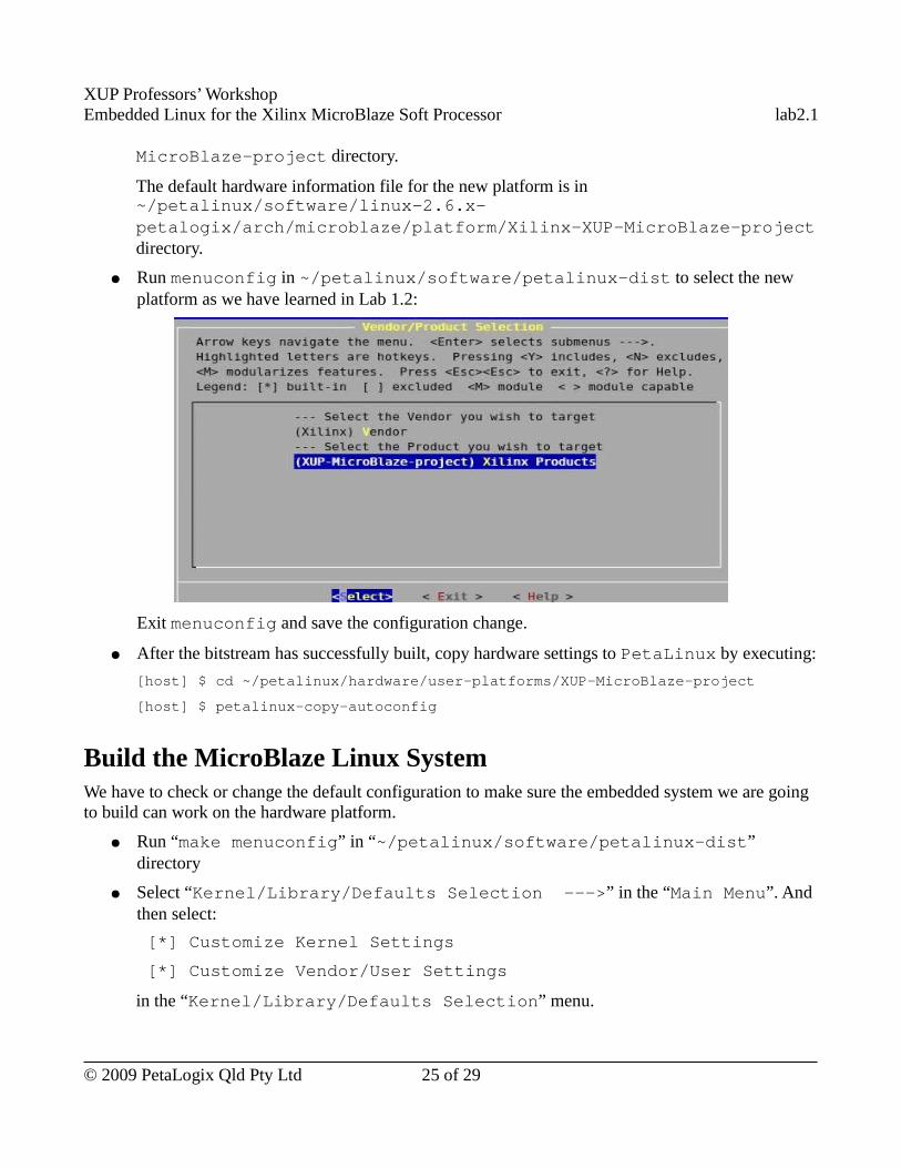
XUP Professors’ WorkshopEmbedded Linux for the Xilinx MicroBlaze Soft Processor lab2.1
MicroBlaze-project directory.
The default hardware information file for the new platform is in ~/petalinux/software/linux-2.6.x-petalogix/arch/microblaze/platform/Xilinx-XUP-MicroBlaze-project directory.
● Run menuconfig in ~/petalinux/software/petalinux-dist to select the new platform as we have learned in Lab 1.2:
Exit menuconfig and save the configuration change.
● After the bitstream has successfully built, copy hardware settings to PetaLinux by executing:
[host] $ cd ~/petalinux/hardware/user-platforms/XUP-MicroBlaze-project
[host] $ petalinux-copy-autoconfig
Build the MicroBlaze Linux SystemWe have to check or change the default configuration to make sure the embedded system we are going to build can work on the hardware platform.
● Run “make menuconfig” in “~/petalinux/software/petalinux-dist” directory
● Select “Kernel/Library/Defaults Selection --->” in the “Main Menu”. And then select:
[*] Customize Kernel Settings
[*] Customize Vendor/User Settings
in the “Kernel/Library/Defaults Selection” menu.
© 2009 PetaLogix Qld Pty Ltd 25 of 29
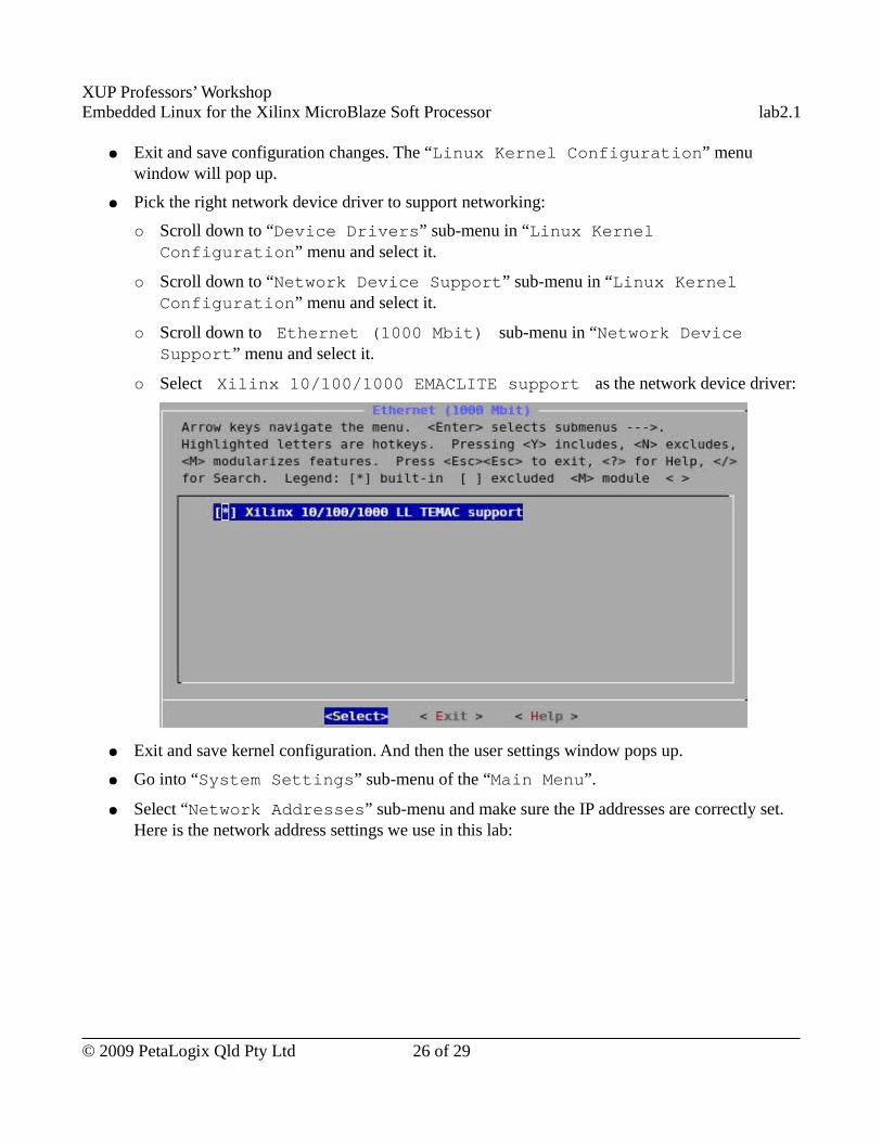
XUP Professors’ WorkshopEmbedded Linux for the Xilinx MicroBlaze Soft Processor lab2.1
● Exit and save configuration changes. The “Linux Kernel Configuration” menu window will pop up.
● Pick the right network device driver to support networking:
○ Scroll down to “Device Drivers” sub-menu in “Linux Kernel Configuration” menu and select it.
○ Scroll down to “Network Device Support” sub-menu in “Linux Kernel Configuration” menu and select it.
○ Scroll down to � Ethernet (1000 Mbit)� sub-menu in “Network Device Support” menu and select it.
○ Select � Xilinx 10/100/1000 EMACLITE support� as the network device driver:
● Exit and save kernel configuration. And then the user settings window pops up.
● Go into “System Settings” sub-menu of the “Main Menu”.
● Select “Network Addresses” sub-menu and make sure the IP addresses are correctly set. Here is the network address settings we use in this lab:
© 2009 PetaLogix Qld Pty Ltd 26 of 29
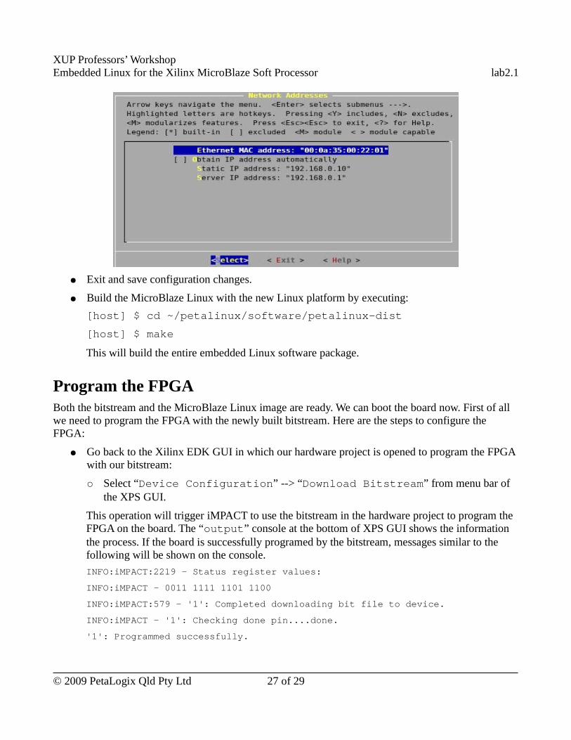
XUP Professors’ WorkshopEmbedded Linux for the Xilinx MicroBlaze Soft Processor lab2.1
● Exit and save configuration changes.
● Build the MicroBlaze Linux with the new Linux platform by executing:
[host] $ cd ~/petalinux/software/petalinux-dist
[host] $ make
This will build the entire embedded Linux software package.
Program the FPGABoth the bitstream and the MicroBlaze Linux image are ready. We can boot the board now. First of all we need to program the FPGA with the newly built bitstream. Here are the steps to configure the FPGA:
● Go back to the Xilinx EDK GUI in which our hardware project is opened to program the FPGA with our bitstream:
○ Select “Device Configuration” --> “Download Bitstream” from menu bar of the XPS GUI.
This operation will trigger iMPACT to use the bitstream in the hardware project to program the FPGA on the board. The “output” console at the bottom of XPS GUI shows the information the process. If the board is successfully programed by the bitstream, messages similar to the following will be shown on the console.
INFO:iMPACT:2219 - Status register values:
INFO:iMPACT - 0011 1111 1101 1100
INFO:iMPACT:579 - '1': Completed downloading bit file to device.
INFO:iMPACT - '1': Checking done pin....done.
'1': Programmed successfully.
© 2009 PetaLogix Qld Pty Ltd 27 of 29

XUP Professors’ WorkshopEmbedded Linux for the Xilinx MicroBlaze Soft Processor lab2.1
Elapsed time = 3 sec.
Done!
● In the kermit window, we should see some outputs from the application used to initialized the BRAM. In this lab, TestApp_Memroy application is configured by default by the Xilnx EDK Base System Builder as the program to initialize BRAM.
If you choose different application to initialize BRAM, the output in the kermit window will be different. E.g., the PetaLinux hardware reference designs use fs-boot to initialize BRAM. If you create your hardware system based on the PetaLinux hardware reference designs as you will learn in the coming labs, the output in the kermit window will be from the fs-boot application after the FPGA is programed by your bitstream.
Boot PetaLinux with JTAGThe FGPA has been programed, now, we can boot PetaLinux on it. Here are the steps to do it:
● Use PetaLinux tool to download the new kernel image to the board on JTAG by executing the following command on the host machine:
[host] $ petalinux-jtag-boot -t 0 -a 0x50000000 -i /tftpboot/image.bin
The “0x50000000” is the base address of the main system memory, if your main memory address is different, please change it to the right one. You can find the address map of the system in the “Address” tab of “System Assembly View” of “Xilinx Platform Studio”.
● When the login prompt comes up in the kermit window. Log in and try command such as “gpio-test”, “ping” and “ifconfig”.
Use Completed ResourceThe completed Linux image for this lab is available in
~/xup_materials/labs/lab2.1/completed/
If you are stuck in any problem in the lab, you are welcome to use the completed resource. Here is the instruction on how to use the completed resource:
● Copy the completed hardware project to PetaLinux tree and the Linux images to /tftpboot directory by executing the following command on the host machine:
[host] $ ~/xup_materials/complete_lab 2.1
● Download the bitstream to the board by executing:
[host] $ cd ~/petalinux/hardware/user-platforms/XUP-MicroBlaze-
© 2009 PetaLogix Qld Pty Ltd 28 of 29
XUP Professors’ WorkshopEmbedded Linux for the Xilinx MicroBlaze Soft Processor lab2.1
project
[host] $ impact -batch etc/download.cmd
This command will download the bitstream implementation/download.bit to the board. (iMPACT is an Xilinx device configuration tool.)
● Boot the board using `petalinux-jtag-boot` by executing:
[host] $ petalinux-jtag-boot -t 0 -a 0x50000000 -i /tftpboot/image.bin
OutcomesAt the completion of this lab you should
● know how to use XPS BSB to create a hardware plartform● know how to build bitstream with PetaLinux support● know how to create new Embedded Linux platform● know how to build Embedded Linux for a hardware platform.
Document VersionDoc ID: lab2_1Build: xupv5-edk113-7425Date: 2010-01-21
© 2009 PetaLogix Qld Pty Ltd 29 of 29
XUP Professors’ WorkshopEmbedded Linux for the Xilinx MicroBlaze Soft Processor lab2.2a
Lab 2.2.a – Custom Hardware Development – PLB PWM
RationaleXilinx provides commonly used bus interfaces for customized IP Core to talk to the rest of the on-chip system. It also provides a customized IP Core creation tool to automatically add the specified bus interface to our IP Core when we use it to create our customized hardware.
The purpose of this lab session is to go through XPS Create and Import Peripheral Wizard and experience one of the commonly used buses, Processor Local Bus (PLB).
Objectives● Design a IP Core in VHDL● Use XPS Create and Import Peripheral Wizard to create customized IP Core● Integrate a IP Core with PLB interface● Use XMD to debug the hardware
IntroductionIn the previous lab, we have learned how to create a hardware platform with BSB. In this lab, we are going to create our PWM core with PLB interface with XPS Create and Import Peripheral Wizard.
Pulse Width Modulation (PWM) is a method of generating analog-like signals from purely digital circuits. By varying the duty cycle of a square wave signal from 0 to 100 percent, and filtering the output through a low-pass filter, analog outputs may be simulated.
We will use multichannel PWM to vary the brightness of 4 User LEDs on the development board. Varying the duty cycle of the LED control signal, and with your eye providing the low pass filtering, you can vary the apparent brightness of the LED from all-off to all-on.
TimeThis session will run for approximately 75 minutes.
PreparationIf this is the first lab you are doing then please refer to sections “Before You Start” of Lab 1.1 document for necessary preparatory information on how to setup the hardware environment.
© 2009 PetaLogix Qld Pty Ltd 1 of 20
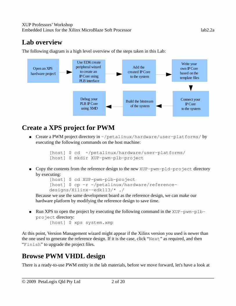
XUP Professors’ WorkshopEmbedded Linux for the Xilinx MicroBlaze Soft Processor lab2.2a
Lab overviewThe following diagram is a high level overview of the steps taken in this Lab:
Create a XPS project for PWM● Create a PWM project directory in ~/petalinux/hardware/user-platforms/ by
executing the following commands on the host machine:
[host] $ cd ~/petalinux/hardware/user-platforms/[host] $ mkdir XUP-pwm-plb-project
● Copy the contents from the reference design to the new XUP-pwm-pld-project directory by executing:
[host] $ cd XUP-pwm-plb-project [host] $ cp -r ~/petalinux/hardware/reference-designs/Xilinx--edk113/* ./
Because we use the same development board as the reference design, we can make our hardware platform by modifying the reference design to save time.
● Run XPS to open the project by executing the following command in the XUP-pwm-plb-project directory:
[host] $ xps system.xmp
At this point, Version Management wizard might appear if the Xilinx version you used is newer than the one used to generate the reference design. If it is the case, click “Next” as required, and then “Finish” to upgrade the project files.
Browse PWM VHDL designThere is a ready-to-use PWM entity in the lab materials, before we move forward, let's have a look at
© 2009 PetaLogix Qld Pty Ltd 2 of 20
Open an XPS hardware project
Use EDK createperipheral wizard
to create an IP Core using PLB interface
Add the created IP Core to the system
Write your own IP Core based on the template files
Build the bitstream of the system
Connect your IP Core
to the system
Debug your PLB IP Core using XMD
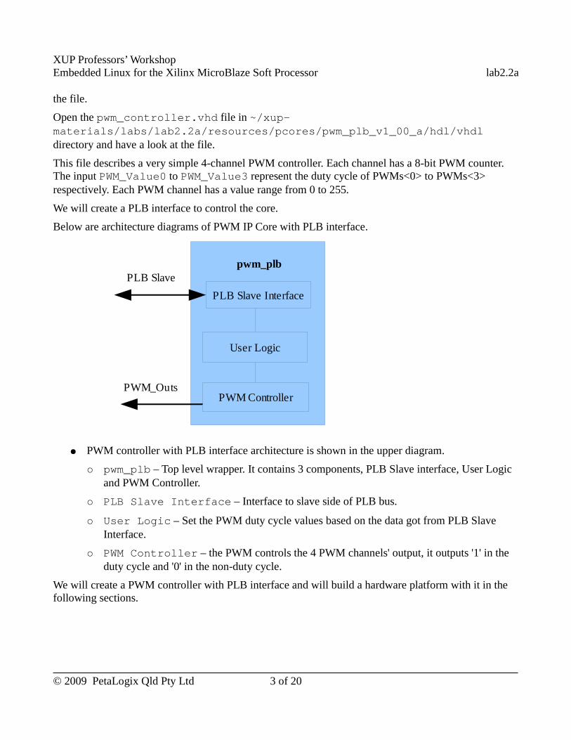
XUP Professors’ WorkshopEmbedded Linux for the Xilinx MicroBlaze Soft Processor lab2.2a
the file.
Open the pwm_controller.vhd file in ~/xup-materials/labs/lab2.2a/resources/pcores/pwm_plb_v1_00_a/hdl/vhdl directory and have a look at the file.
This file describes a very simple 4-channel PWM controller. Each channel has a 8-bit PWM counter. The input PWM_Value0 to PWM_Value3 represent the duty cycle of PWMs<0> to PWMs<3> respectively. Each PWM channel has a value range from 0 to 255.
We will create a PLB interface to control the core.
Below are architecture diagrams of PWM IP Core with PLB interface.
● PWM controller with PLB interface architecture is shown in the upper diagram.
○ pwm_plb – Top level wrapper. It contains 3 components, PLB Slave interface, User Logic and PWM Controller.
○ PLB Slave Interface – Interface to slave side of PLB bus.
○ User Logic – Set the PWM duty cycle values based on the data got from PLB Slave Interface.
○ PWM Controller – the PWM controls the 4 PWM channels' output, it outputs '1' in the duty cycle and '0' in the non-duty cycle.
We will create a PWM controller with PLB interface and will build a hardware platform with it in the following sections.
© 2009 PetaLogix Qld Pty Ltd 3 of 20
PLB Slave Interface
User Logic
pwm_plb
PWM Controller
PLB Slave
PWM_Outs
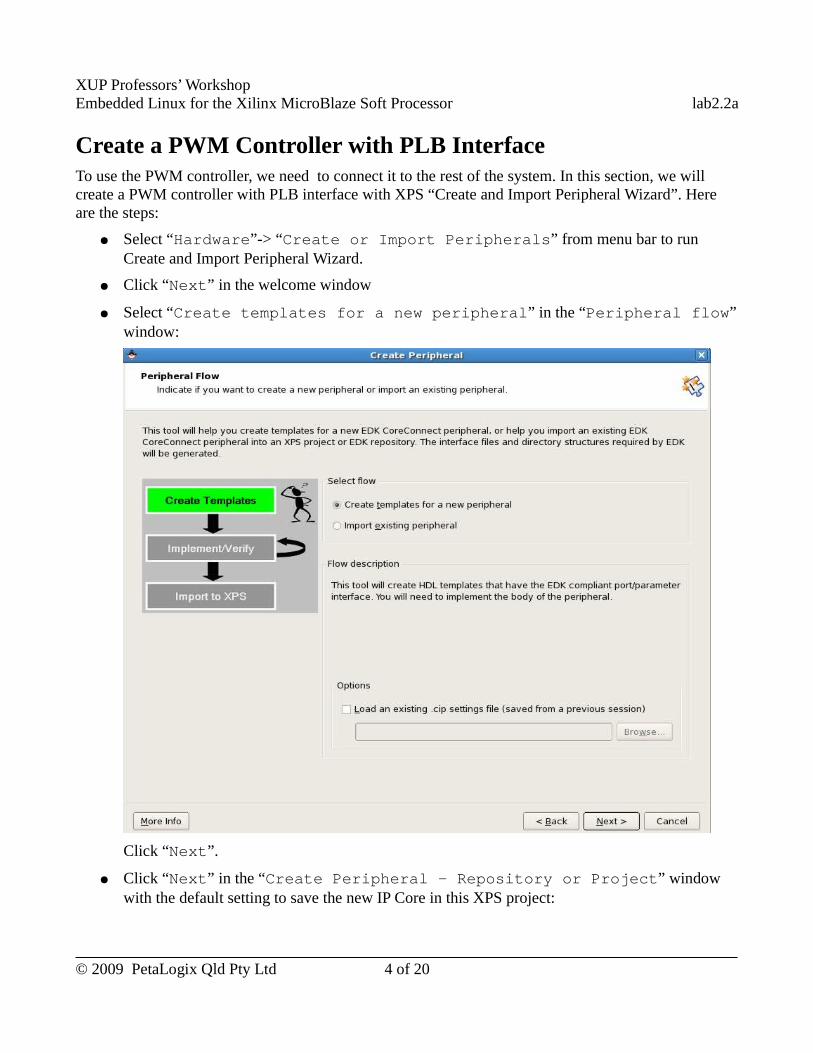
XUP Professors’ WorkshopEmbedded Linux for the Xilinx MicroBlaze Soft Processor lab2.2a
Create a PWM Controller with PLB InterfaceTo use the PWM controller, we need to connect it to the rest of the system. In this section, we will create a PWM controller with PLB interface with XPS “Create and Import Peripheral Wizard”. Here are the steps:
● Select “Hardware”-> “Create or Import Peripherals” from menu bar to run Create and Import Peripheral Wizard.
● Click “Next” in the welcome window
● Select “Create templates for a new peripheral” in the “Peripheral flow” window:
Click “Next”.
● Click “Next” in the “Create Peripheral - Repository or Project” window with the default setting to save the new IP Core in this XPS project:
© 2009 PetaLogix Qld Pty Ltd 4 of 20
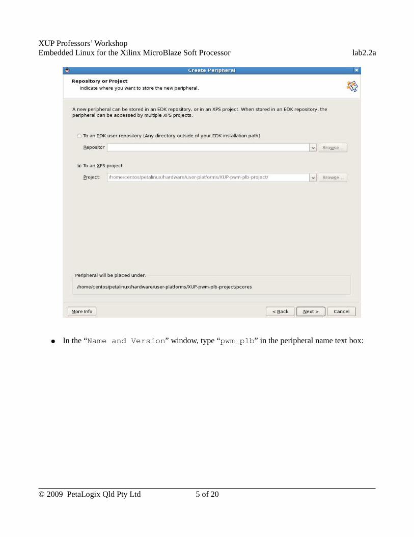
XUP Professors’ WorkshopEmbedded Linux for the Xilinx MicroBlaze Soft Processor lab2.2a
● In the “Name and Version” window, type “pwm_plb” in the peripheral name text box:
© 2009 PetaLogix Qld Pty Ltd 5 of 20
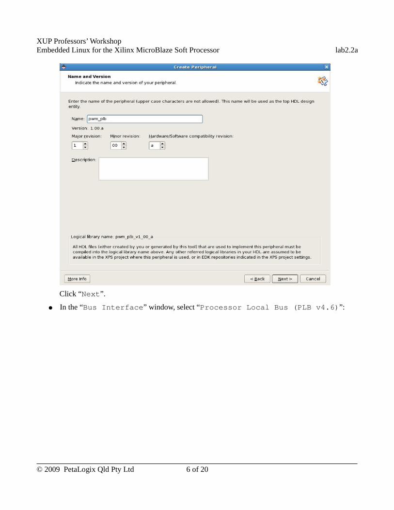
XUP Professors’ WorkshopEmbedded Linux for the Xilinx MicroBlaze Soft Processor lab2.2a
Click “Next”.
● In the “Bus Interface” window, select “Processor Local Bus (PLB v4.6)”:
© 2009 PetaLogix Qld Pty Ltd 6 of 20
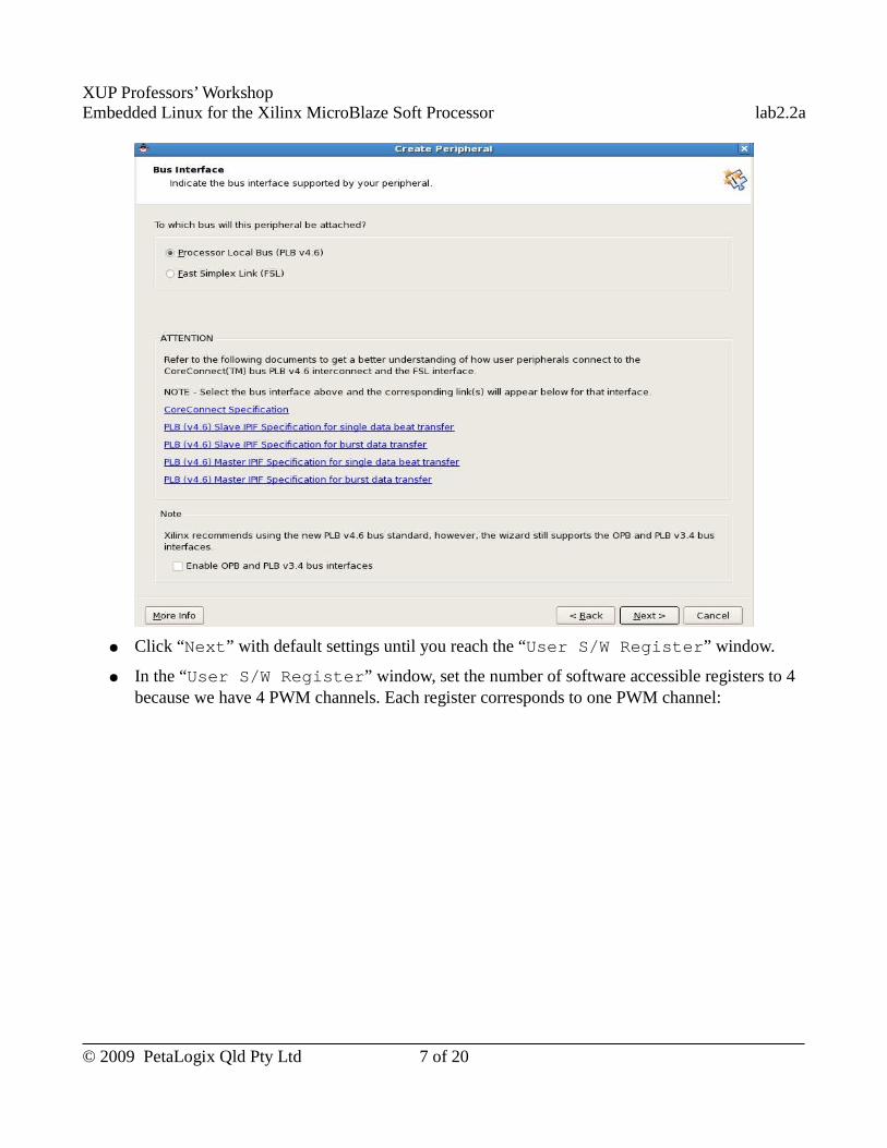
XUP Professors’ WorkshopEmbedded Linux for the Xilinx MicroBlaze Soft Processor lab2.2a
● Click “Next” with default settings until you reach the “User S/W Register” window.
● In the “User S/W Register” window, set the number of software accessible registers to 4 because we have 4 PWM channels. Each register corresponds to one PWM channel:
© 2009 PetaLogix Qld Pty Ltd 7 of 20
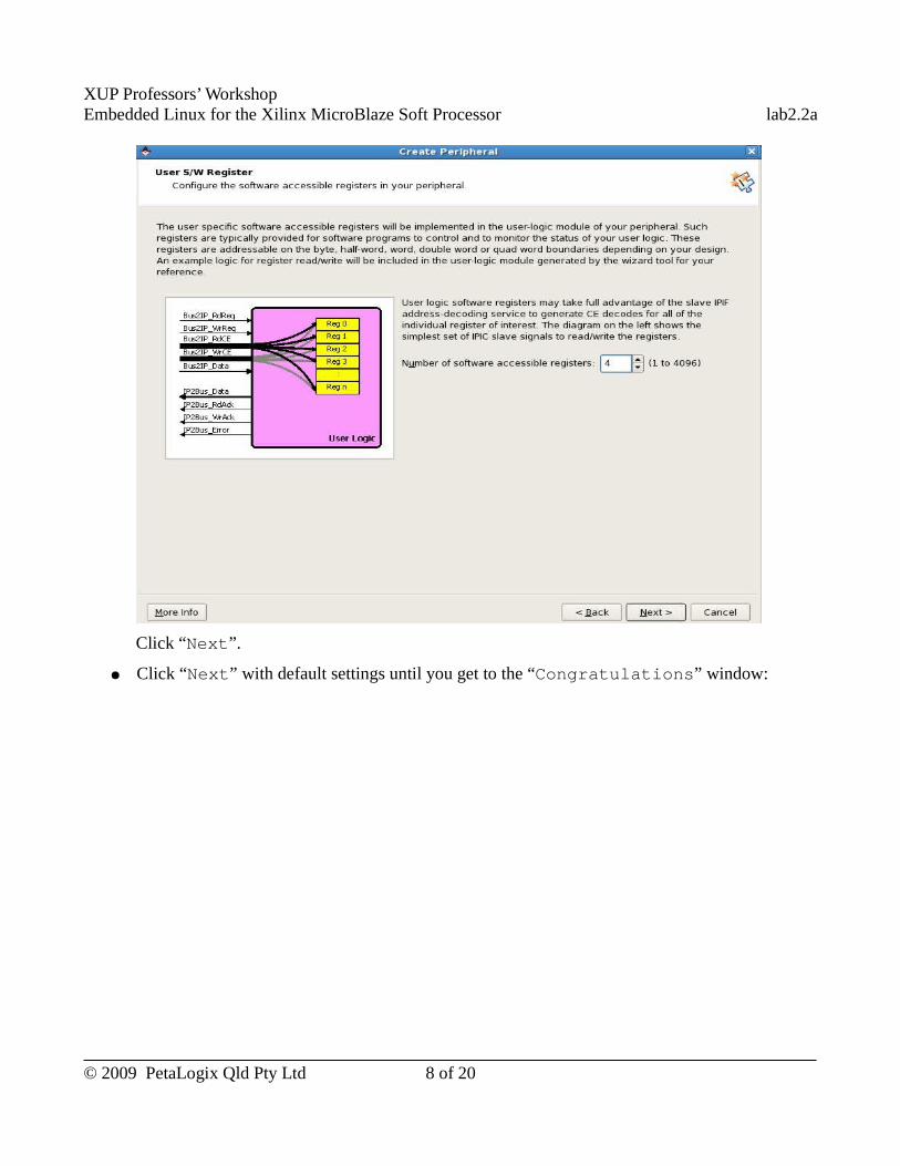
XUP Professors’ WorkshopEmbedded Linux for the Xilinx MicroBlaze Soft Processor lab2.2a
Click “Next”.
● Click “Next” with default settings until you get to the “Congratulations” window:
© 2009 PetaLogix Qld Pty Ltd 8 of 20
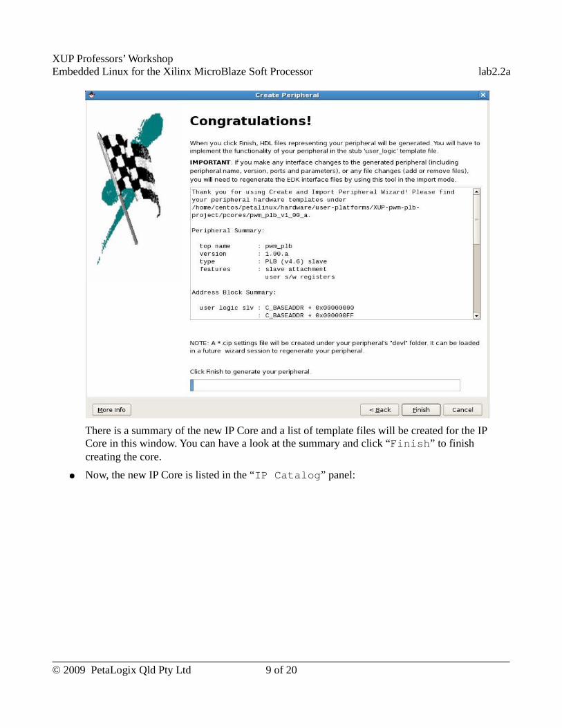
XUP Professors’ WorkshopEmbedded Linux for the Xilinx MicroBlaze Soft Processor lab2.2a
There is a summary of the new IP Core and a list of template files will be created for the IP Core in this window. You can have a look at the summary and click “Finish” to finish creating the core.
● Now, the new IP Core is listed in the “IP Catalog” panel:
© 2009 PetaLogix Qld Pty Ltd 9 of 20
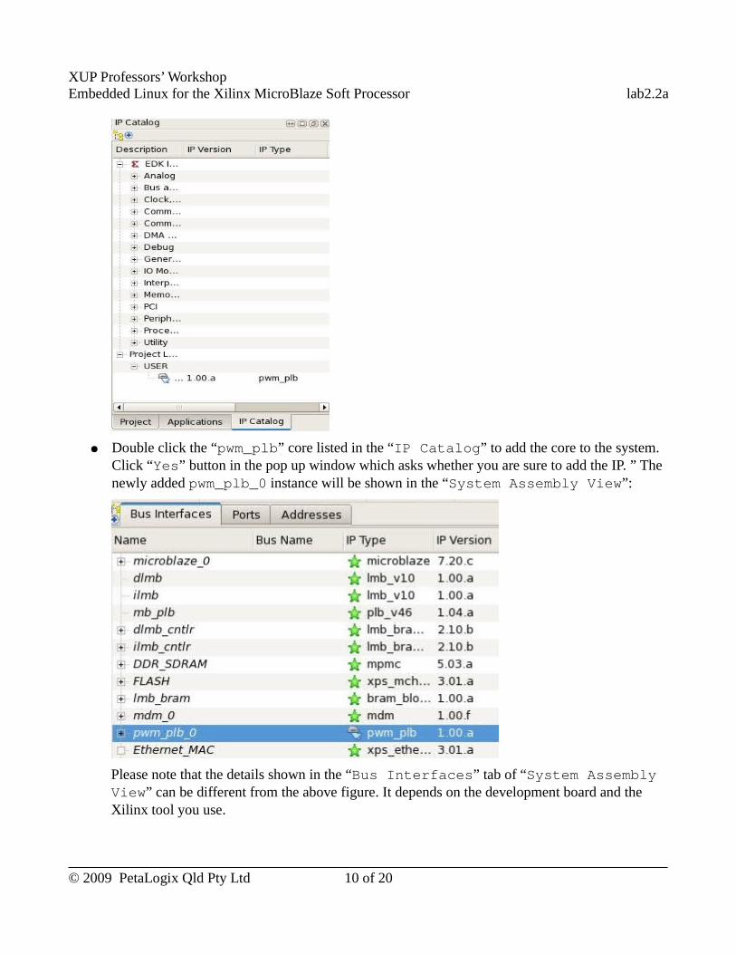
XUP Professors’ WorkshopEmbedded Linux for the Xilinx MicroBlaze Soft Processor lab2.2a
● Double click the “pwm_plb” core listed in the “IP Catalog” to add the core to the system. Click “Yes” button in the pop up window which asks whether you are sure to add the IP. ” The newly added pwm_plb_0 instance will be shown in the “System Assembly View”:
Please note that the details shown in the “Bus Interfaces” tab of “System Assembly View” can be different from the above figure. It depends on the development board and the Xilinx tool you use.
© 2009 PetaLogix Qld Pty Ltd 10 of 20
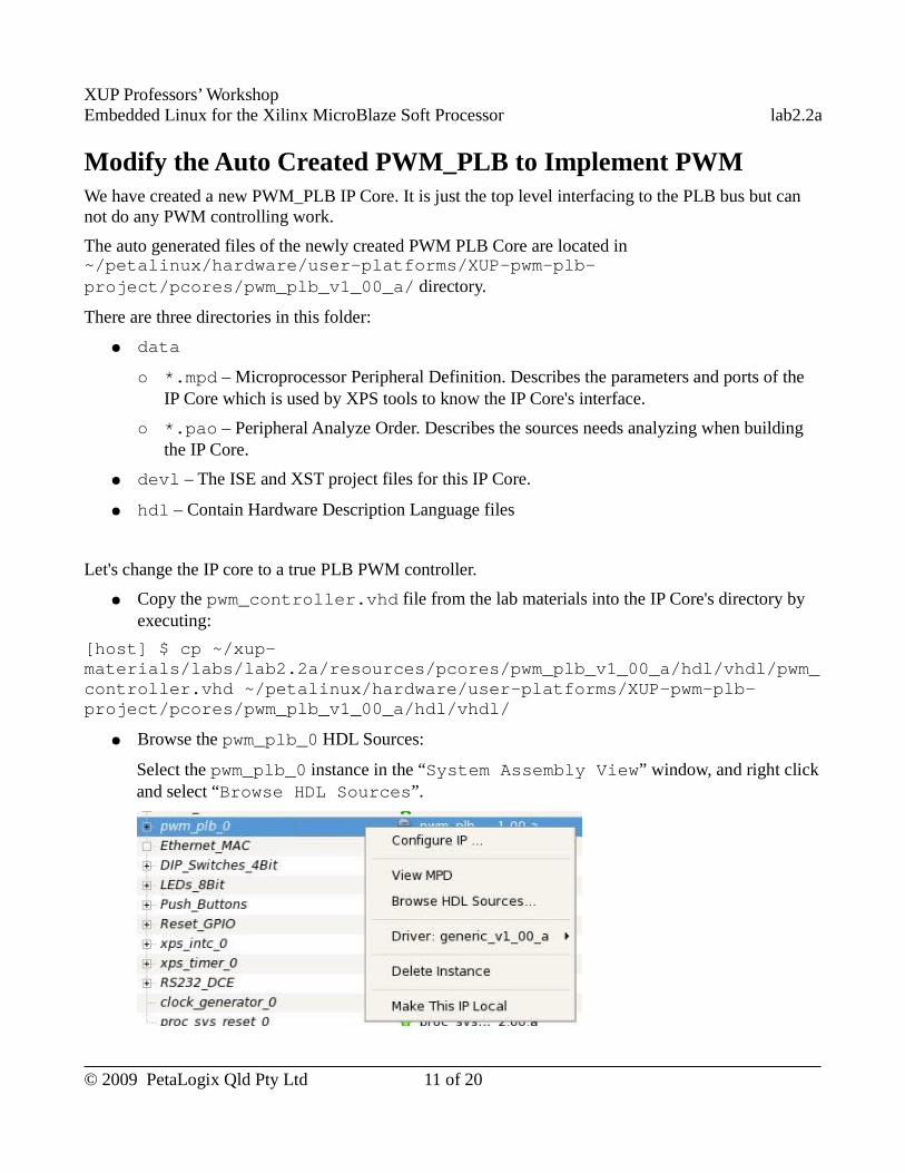
XUP Professors’ WorkshopEmbedded Linux for the Xilinx MicroBlaze Soft Processor lab2.2a
Modify the Auto Created PWM_PLB to Implement PWMWe have created a new PWM_PLB IP Core. It is just the top level interfacing to the PLB bus but can not do any PWM controlling work.
The auto generated files of the newly created PWM PLB Core are located in ~/petalinux/hardware/user-platforms/XUP-pwm-plb-project/pcores/pwm_plb_v1_00_a/ directory.
There are three directories in this folder:
● data
○ *.mpd – Microprocessor Peripheral Definition. Describes the parameters and ports of the IP Core which is used by XPS tools to know the IP Core's interface.
○ *.pao – Peripheral Analyze Order. Describes the sources needs analyzing when building the IP Core.
● devl – The ISE and XST project files for this IP Core.
● hdl – Contain Hardware Description Language files
Let's change the IP core to a true PLB PWM controller.
● Copy the pwm_controller.vhd file from the lab materials into the IP Core's directory by executing:
[host] $ cp ~/xup-materials/labs/lab2.2a/resources/pcores/pwm_plb_v1_00_a/hdl/vhdl/pwm_controller.vhd ~/petalinux/hardware/user-platforms/XUP-pwm-plb-project/pcores/pwm_plb_v1_00_a/hdl/vhdl/
● Browse the pwm_plb_0 HDL Sources:
Select the pwm_plb_0 instance in the “System Assembly View” window, and right click and select “Browse HDL Sources”.
© 2009 PetaLogix Qld Pty Ltd 11 of 20
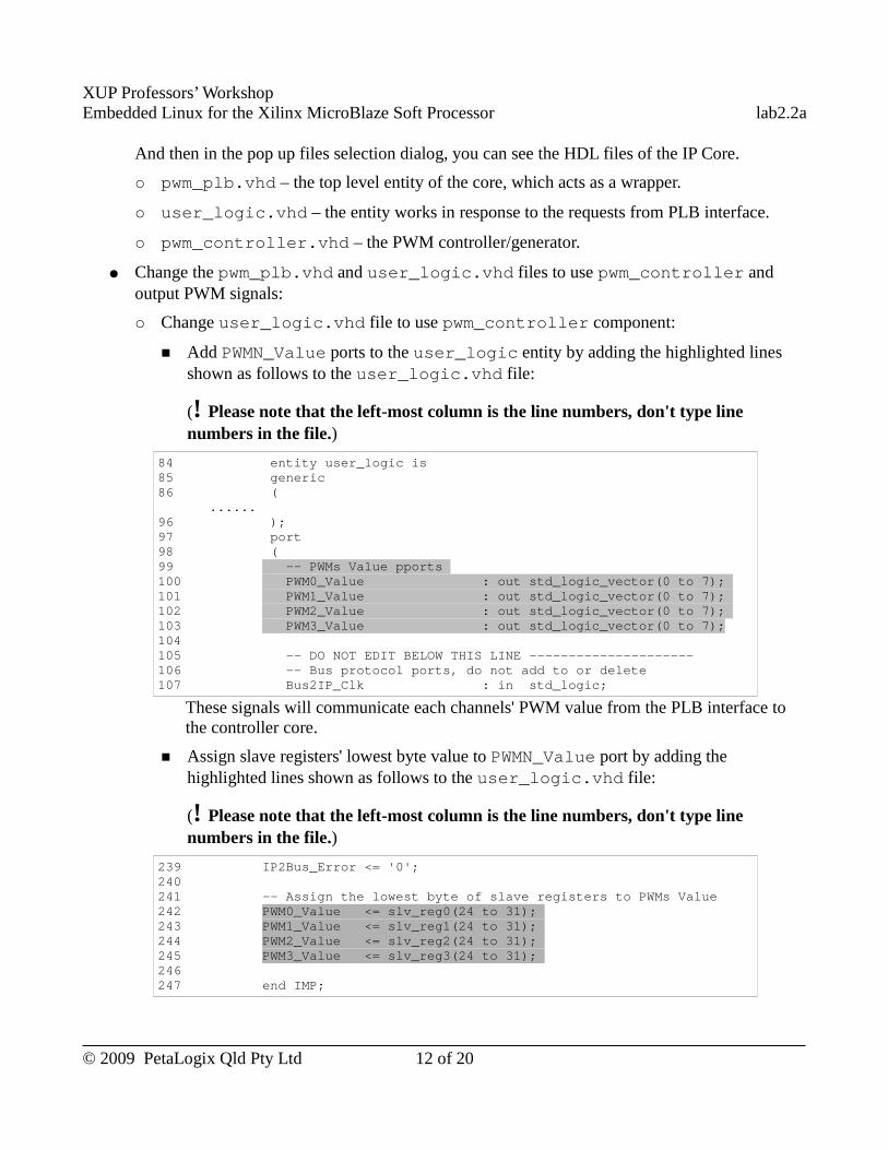
XUP Professors’ WorkshopEmbedded Linux for the Xilinx MicroBlaze Soft Processor lab2.2a
And then in the pop up files selection dialog, you can see the HDL files of the IP Core.
○ pwm_plb.vhd – the top level entity of the core, which acts as a wrapper.
○ user_logic.vhd – the entity works in response to the requests from PLB interface.
○ pwm_controller.vhd – the PWM controller/generator.
● Change the pwm_plb.vhd and user_logic.vhd files to use pwm_controller and output PWM signals:
○ Change user_logic.vhd file to use pwm_controller component:
■ Add PWMN_Value ports to the user_logic entity by adding the highlighted lines shown as follows to the user_logic.vhd file:
(! Please note that the left-most column is the line numbers, don't type line numbers in the file.)
84 entity user_logic is 85 generic 86 (
......96 ); 97 port 98 ( 99 -- PWMs Value pports 100 PWM0_Value : out std_logic_vector(0 to 7); 101 PWM1_Value : out std_logic_vector(0 to 7); 102 PWM2_Value : out std_logic_vector(0 to 7); 103 PWM3_Value : out std_logic_vector(0 to 7);104 105 -- DO NOT EDIT BELOW THIS LINE --------------------- 106 -- Bus protocol ports, do not add to or delete 107 Bus2IP_Clk : in std_logic;
These signals will communicate each channels' PWM value from the PLB interface to the controller core.
■ Assign slave registers' lowest byte value to PWMN_Value port by adding the highlighted lines shown as follows to the user_logic.vhd file:
(! Please note that the left-most column is the line numbers, don't type line numbers in the file.)
239 IP2Bus_Error <= '0'; 240241 -- Assign the lowest byte of slave registers to PWMs Value 242 PWM0_Value <= slv_reg0(24 to 31); 243 PWM1_Value <= slv_reg1(24 to 31); 244 PWM2_Value <= slv_reg2(24 to 31); 245 PWM3_Value <= slv_reg3(24 to 31); 246 247 end IMP;
© 2009 PetaLogix Qld Pty Ltd 12 of 20
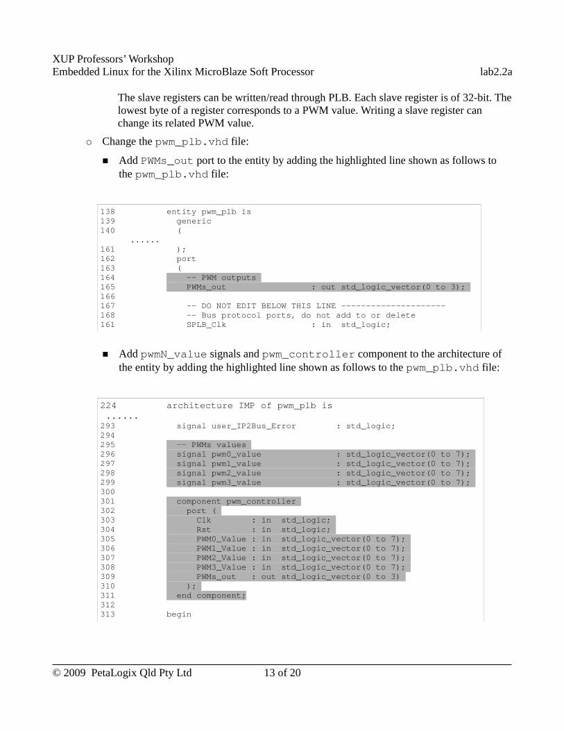
XUP Professors’ WorkshopEmbedded Linux for the Xilinx MicroBlaze Soft Processor lab2.2a
The slave registers can be written/read through PLB. Each slave register is of 32-bit. The lowest byte of a register corresponds to a PWM value. Writing a slave register can change its related PWM value.
○ Change the pwm_plb.vhd file:
■ Add PWMs_out port to the entity by adding the highlighted line shown as follows to the pwm_plb.vhd file:
138 entity pwm_plb is139 generic140 ( ......161 ); 162 port 163 ( 164 -- PWM outputs 165 PWMs_out : out std_logic_vector(0 to 3); 166 167 -- DO NOT EDIT BELOW THIS LINE --------------------- 168 -- Bus protocol ports, do not add to or delete 161 SPLB_Clk : in std_logic;
■ Add pwmN_value signals and pwm_controller component to the architecture of the entity by adding the highlighted line shown as follows to the pwm_plb.vhd file:
224 architecture IMP of pwm_plb is ......293 signal user_IP2Bus_Error : std_logic; 294295 -- PWMs values 296 signal pwm0_value : std_logic_vector(0 to 7); 297 signal pwm1_value : std_logic_vector(0 to 7); 298 signal pwm2_value : std_logic_vector(0 to 7); 299 signal pwm3_value : std_logic_vector(0 to 7); 300301 component pwm_controller 302 port ( 303 Clk : in std_logic; 304 Rst : in std_logic; 305 PWM0_Value : in std_logic_vector(0 to 7); 306 PWM1_Value : in std_logic_vector(0 to 7); 307 PWM2_Value : in std_logic_vector(0 to 7); 308 PWM3_Value : in std_logic_vector(0 to 7); 309 PWMs_out : out std_logic_vector(0 to 3) 310 ); 311 end component; 312313 begin
© 2009 PetaLogix Qld Pty Ltd 13 of 20
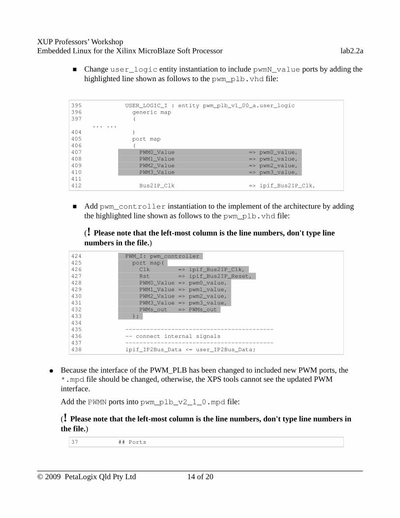
XUP Professors’ WorkshopEmbedded Linux for the Xilinx MicroBlaze Soft Processor lab2.2a
■ Change user_logic entity instantiation to include pwmN_value ports by adding the highlighted line shown as follows to the pwm_plb.vhd file:
395 USER_LOGIC_I : entity pwm_plb_v1_00_a.user_logic 396 generic map 397 ( ... ...404 ) 405 port map 406 ( 407 PWM0_Value => pwm0_value, 408 PWM1_Value => pwm1_value, 409 PWM2_Value => pwm2_value, 410 PWM3_Value => pwm3_value, 411 412 Bus2IP_Clk => ipif_Bus2IP_Clk,
■ Add pwm_controller instantiation to the implement of the architecture by adding the highlighted line shown as follows to the pwm_plb.vhd file:
(! Please note that the left-most column is the line numbers, don't type line numbers in the file.)
424 PWM_I: pwm_controller 425 port map( 426 Clk => ipif_Bus2IP_Clk, 427 Rst => ipif_Bus2IP_Reset, 428 PWM0_Value => pwm0_value, 429 PWM1_Value => pwm1_value, 430 PWM2_Value => pwm2_value, 431 PWM3_Value => pwm3_value, 432 PWMs_out => PWMs_out 433 ); 434 435 ------------------------------------------ 436 -- connect internal signals 437 ------------------------------------------ 438 ipif_IP2Bus_Data <= user_IP2Bus_Data;
● Because the interface of the PWM_PLB has been changed to included new PWM ports, the *.mpd file should be changed, otherwise, the XPS tools cannot see the updated PWM interface.
Add the PWMN ports into pwm_plb_v2_1_0.mpd file:
(! Please note that the left-most column is the line numbers, don't type line numbers in the file.)
37 ## Ports
© 2009 PetaLogix Qld Pty Ltd 14 of 20
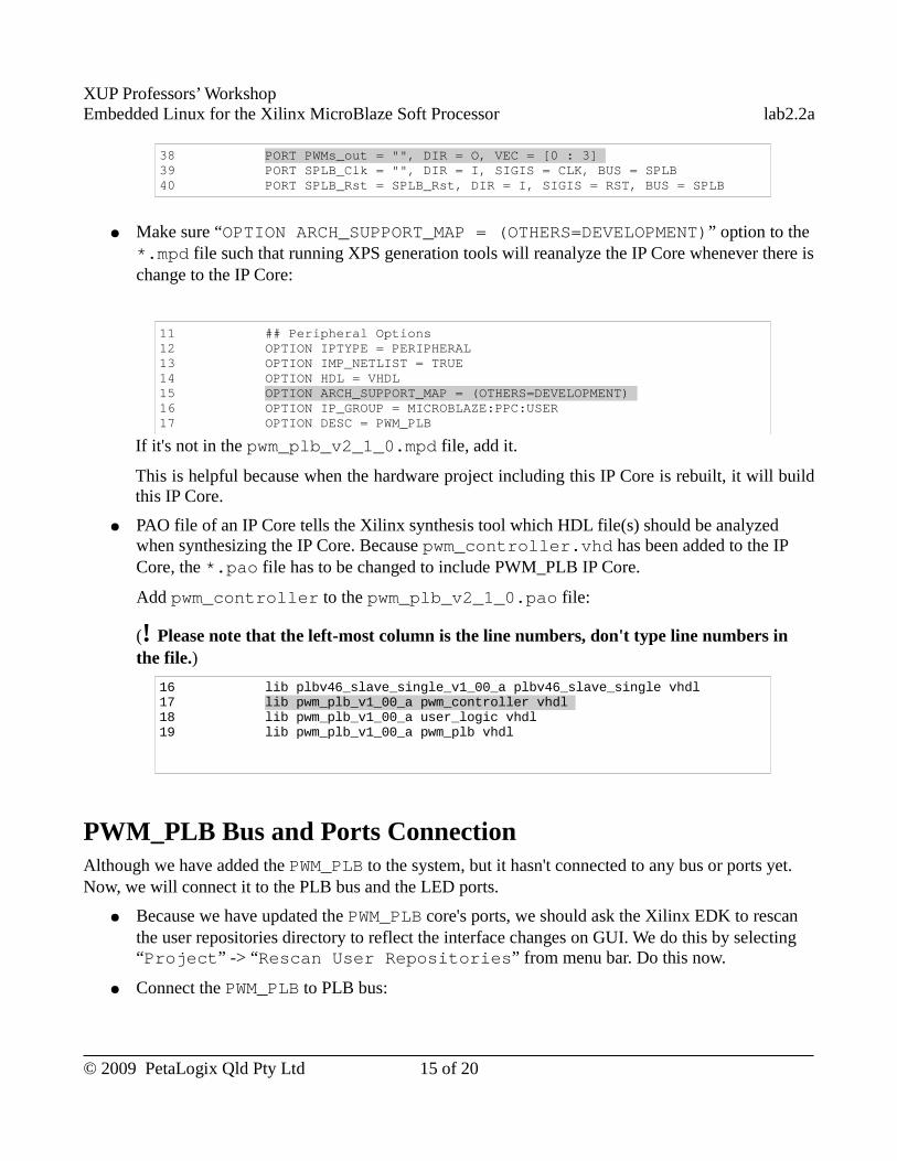
XUP Professors’ WorkshopEmbedded Linux for the Xilinx MicroBlaze Soft Processor lab2.2a
38 PORT PWMs_out = "", DIR = O, VEC = [0 : 3] 39 PORT SPLB_Clk = "", DIR = I, SIGIS = CLK, BUS = SPLB 40 PORT SPLB_Rst = SPLB_Rst, DIR = I, SIGIS = RST, BUS = SPLB
● Make sure “OPTION ARCH_SUPPORT_MAP = (OTHERS=DEVELOPMENT)” option to the *.mpd file such that running XPS generation tools will reanalyze the IP Core whenever there is change to the IP Core:
11 ## Peripheral Options 12 OPTION IPTYPE = PERIPHERAL 13 OPTION IMP_NETLIST = TRUE 14 OPTION HDL = VHDL 15 OPTION ARCH_SUPPORT_MAP = (OTHERS=DEVELOPMENT) 16 OPTION IP_GROUP = MICROBLAZE:PPC:USER 17 OPTION DESC = PWM_PLB
If it's not in the pwm_plb_v2_1_0.mpd file, add it.
This is helpful because when the hardware project including this IP Core is rebuilt, it will build this IP Core.
● PAO file of an IP Core tells the Xilinx synthesis tool which HDL file(s) should be analyzed when synthesizing the IP Core. Because pwm_controller.vhd has been added to the IP Core, the *.pao file has to be changed to include PWM_PLB IP Core.
Add pwm_controller to the pwm_plb_v2_1_0.pao file:
(! Please note that the left-most column is the line numbers, don't type line numbers in the file.)
16 lib plbv46_slave_single_v1_00_a plbv46_slave_single vhdl 17 lib pwm_plb_v1_00_a pwm_controller vhdl 18 lib pwm_plb_v1_00_a user_logic vhdl 19 lib pwm_plb_v1_00_a pwm_plb vhdl
PWM_PLB Bus and Ports ConnectionAlthough we have added the PWM_PLB to the system, but it hasn't connected to any bus or ports yet. Now, we will connect it to the PLB bus and the LED ports.
● Because we have updated the PWM_PLB core's ports, we should ask the Xilinx EDK to rescan the user repositories directory to reflect the interface changes on GUI. We do this by selecting “Project” -> “Rescan User Repositories” from menu bar. Do this now.
● Connect the PWM_PLB to PLB bus:
© 2009 PetaLogix Qld Pty Ltd 15 of 20
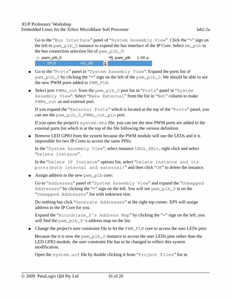
XUP Professors’ WorkshopEmbedded Linux for the Xilinx MicroBlaze Soft Processor lab2.2a
Go to the “Bus Interface” panel of “System Assembly View”. Click the “+” sign on the left to pwm_plb_0 instance to expend the bus interface of the IP Core. Select mb_plb in the bus connection selection list of pwm_plb_0:
● Go to the “Ports” panel in “System Assembly View”. Expand the ports list of pwm_plb_0 by clicking the “+” sign on the left of the pwm_plb_0. We should be able to see the new PWM ports added to PWM_PLB.
● Select port PWMs_out from the pwm_plb_0 port list in “Ports” panel in “System Assembly View”. Select “Make External” from the list in “Net” column to make PWMs_out as and external port.
If you expand the “External Ports” which is located at the top of the “Ports” panel, you can see the pwm_plb_0_PWMs_out_pin port.
If you open the project's system.mhs file, you can see the new PWM ports are added to the external ports list which is at the top of the file following the version definition.
● Remove LED GPIO from the system because the PWM module will use the LEDs and it is impossible for two IP Cores to access the same PINs:
In the “System Assembly View”, select instance LEDs_8Bit, right click and select “Delete Instance”.
In the “Delete IP Instance” options list, select “Delete instance and its ports(both internal and external)” and then click “OK” to delete the instance.
● Assign address to the new pwm_plb core:
Go to “Addresses” panel of “System Assembly View” and expand the “Unmapped Addresses” by clicking the “+” sign on the left. You will see pwm_plb_0 is on the “Unmapped Addresses” list with unknown size.
Do nothing but click “Generate Addresses” at the right top corner. XPS will assign address to the IP Core for you.
Expand the “microblaze_0's Address Map” by clicking the “+” sign on the left, you will find the pwm_plb_0's address map on the list.
● Change the project's user constraint file to let the PWM_PLB core to access the user LEDs pins:
Because the it is now the pwm_plb_0 instance to access the user LEDs pins rather than the LED GPIO module, the user constraint file has to be changed to reflect this system modification.
Open the system.ucf file by double clicking it from “Project Files” list in
© 2009 PetaLogix Qld Pty Ltd 16 of 20
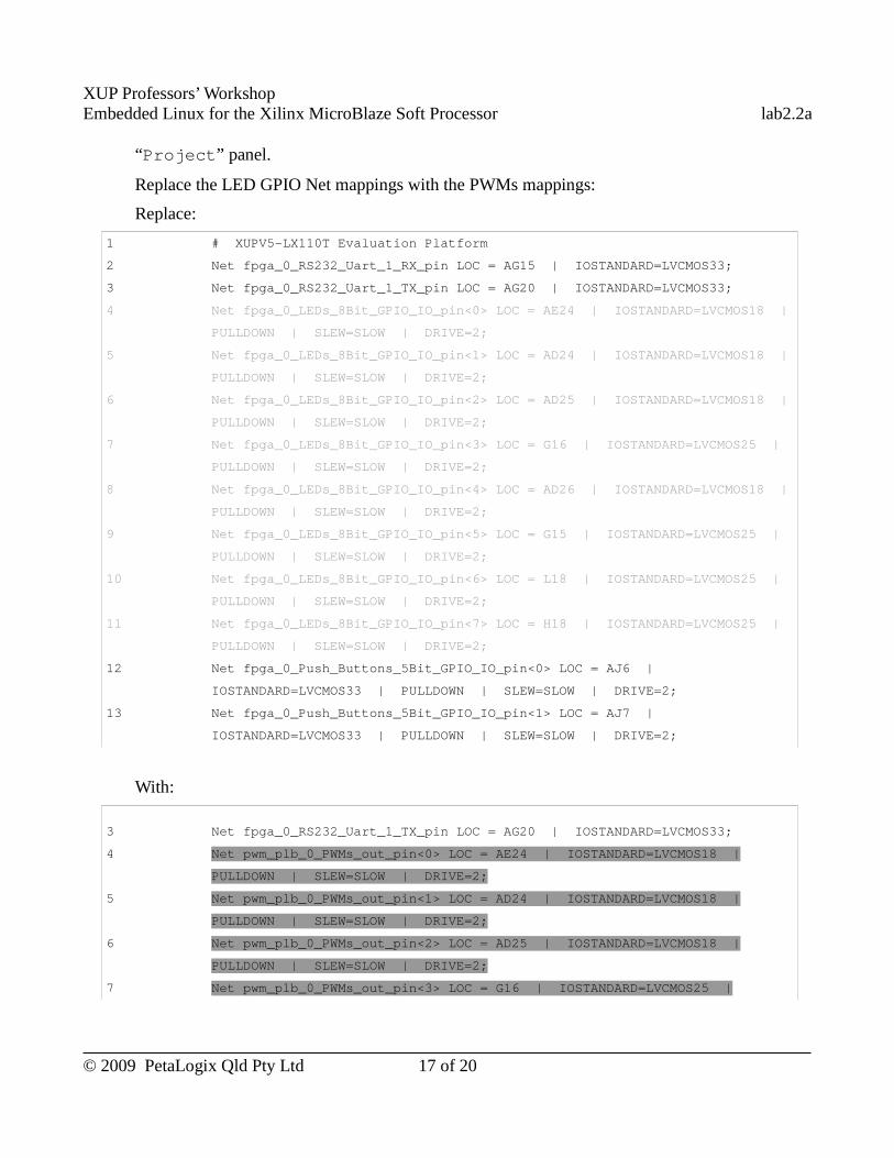
XUP Professors’ WorkshopEmbedded Linux for the Xilinx MicroBlaze Soft Processor lab2.2a
“Project” panel.
Replace the LED GPIO Net mappings with the PWMs mappings:
Replace:
1 # XUPV5-LX110T Evaluation Platform
2 Net fpga_0_RS232_Uart_1_RX_pin LOC = AG15 | IOSTANDARD=LVCMOS33;
3 Net fpga_0_RS232_Uart_1_TX_pin LOC = AG20 | IOSTANDARD=LVCMOS33;
4 Net fpga_0_LEDs_8Bit_GPIO_IO_pin<0> LOC = AE24 | IOSTANDARD=LVCMOS18 |
PULLDOWN | SLEW=SLOW | DRIVE=2;
5 Net fpga_0_LEDs_8Bit_GPIO_IO_pin<1> LOC = AD24 | IOSTANDARD=LVCMOS18 |
PULLDOWN | SLEW=SLOW | DRIVE=2;
6 Net fpga_0_LEDs_8Bit_GPIO_IO_pin<2> LOC = AD25 | IOSTANDARD=LVCMOS18 |
PULLDOWN | SLEW=SLOW | DRIVE=2;
7 Net fpga_0_LEDs_8Bit_GPIO_IO_pin<3> LOC = G16 | IOSTANDARD=LVCMOS25 |
PULLDOWN | SLEW=SLOW | DRIVE=2;
8 Net fpga_0_LEDs_8Bit_GPIO_IO_pin<4> LOC = AD26 | IOSTANDARD=LVCMOS18 |
PULLDOWN | SLEW=SLOW | DRIVE=2;
9 Net fpga_0_LEDs_8Bit_GPIO_IO_pin<5> LOC = G15 | IOSTANDARD=LVCMOS25 |
PULLDOWN | SLEW=SLOW | DRIVE=2;
10 Net fpga_0_LEDs_8Bit_GPIO_IO_pin<6> LOC = L18 | IOSTANDARD=LVCMOS25 |
PULLDOWN | SLEW=SLOW | DRIVE=2;
11 Net fpga_0_LEDs_8Bit_GPIO_IO_pin<7> LOC = H18 | IOSTANDARD=LVCMOS25 |
PULLDOWN | SLEW=SLOW | DRIVE=2;
12 Net fpga_0_Push_Buttons_5Bit_GPIO_IO_pin<0> LOC = AJ6 |
IOSTANDARD=LVCMOS33 | PULLDOWN | SLEW=SLOW | DRIVE=2;
13 Net fpga_0_Push_Buttons_5Bit_GPIO_IO_pin<1> LOC = AJ7 |
IOSTANDARD=LVCMOS33 | PULLDOWN | SLEW=SLOW | DRIVE=2;
With:
3 Net fpga_0_RS232_Uart_1_TX_pin LOC = AG20 | IOSTANDARD=LVCMOS33;
4 Net pwm_plb_0_PWMs_out_pin<0> LOC = AE24 | IOSTANDARD=LVCMOS18 |
PULLDOWN | SLEW=SLOW | DRIVE=2;
5 Net pwm_plb_0_PWMs_out_pin<1> LOC = AD24 | IOSTANDARD=LVCMOS18 |
PULLDOWN | SLEW=SLOW | DRIVE=2;
6 Net pwm_plb_0_PWMs_out_pin<2> LOC = AD25 | IOSTANDARD=LVCMOS18 |
PULLDOWN | SLEW=SLOW | DRIVE=2;
7 Net pwm_plb_0_PWMs_out_pin<3> LOC = G16 | IOSTANDARD=LVCMOS25 |
© 2009 PetaLogix Qld Pty Ltd 17 of 20
XUP Professors’ WorkshopEmbedded Linux for the Xilinx MicroBlaze Soft Processor lab2.2a
PULLDOWN | SLEW=SLOW | DRIVE=2;
8 Net fpga_0_Push_Buttons_5Bit_GPIO_IO_pin<0> LOC = AJ6 |
IOSTANDARD=LVCMOS33 | PULLDOWN | SLEW=SLOW | DRIVE=2;
Build BitstreamBuild the bitstream with Xilinx EDK GUI as we have learned in Lab 2.1. If it is your first lab, please refer to section “Build the Hardware Bitstream” section in the Lab 2.1 manual.
Download Bitstream to the BoardNow, we can program the FPGA with the newly built bitstream as we have learned in section “Program the FPGA” in the Lab 2.1 manual.
Debug the PWM with PLB IP Core With XMDLow level hardware debug is useful when testing new Hardware IP Core, otherwise, if we combine the hardware test, driver test and application test together, it is hard to tell whether it is a hardware problem or a software problem if there is a problem.
Xilinx Microprocessor Debugger(XMD) allows us directly write PLB registers. In this section, we will use XMD to debug our PWM with PLB IP Core. The XMD provides powerful debug functions, please refer to Xilinx documents or XPS help for more information.
Let's start debugging our PWM PLB core using XMD:
● Run XMD from command line in the working directory from the host machine by executing:
[host] $ xmd
● After the XMD started, connect XMD to the target by executing the following XMD command in the XMD console on the host machine:
XMD% connect mb mdm
● Stop the running application on MicroBlaze:
Because the board is boot up with application to initialize BRAM and we cannot access registers when application is running on MicroBlaze, before accessing PWM PLB registers, we have to stop the running application. Here is the XMD command to stop the running application:
XMD% stop
● Test our PWM PLB core by writing duty cycle values (0 ~ 255) to the PWM PLB registers, watch the LED status change on the board and read the PWM PLB core registers value back.
© 2009 PetaLogix Qld Pty Ltd 18 of 20
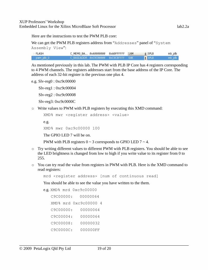
XUP Professors’ WorkshopEmbedded Linux for the Xilinx MicroBlaze Soft Processor lab2.2a
Here are the instructions to test the PWM PLB core:
We can get the PWM PLB registers address from “Addresses” panel of “System Assembly View”:
As mentioned previously in this lab. The PWM with PLB IP Core has 4 registers corresponding to 4 PWM channels. The registers addresses start from the base address of the IP Core. The address of each 32-bit register is the previous one plus 4.
e.g. Slv-reg0 : 0xc9c00000
Slv-reg1 : 0xc9c00004
Slv-reg2 : 0xc9c00008
Slv-reg3: 0xc9c0000C
○ Write values to PWM with PLB registers by executing this XMD command:
XMD% mwr <register address> <value>
e.g.
XMD% mwr 0xc9c00000 100
The GPIO LED 7 will be on.
PWM with PLB registers 0 ~ 3 corresponds to GPIO LED 7 ~ 4.
○ Try writing different values to different PWM with PLB registers. You should be able to see the LED brightness is changed from low to high if you write value to its register from 0 to 255.
○ You can try read the value from registers in PWM with PLB. Here is the XMD command to read registers:
mrd <register address> [num of continuous read]
You should be able to see the value you have written to the them.
e.g. XMD% mrd 0xc9c00000
C9C00000: 00000064
XMD% mrd 0xc9c00000 4
C9C00000: 00000064
C9C00004: 00000064
C9C00008: 00000032
C9C0000C: 000000FF
© 2009 PetaLogix Qld Pty Ltd 19 of 20
XUP Professors’ WorkshopEmbedded Linux for the Xilinx MicroBlaze Soft Processor lab2.2a
○ Exit xmd by typing XMD exit command:
XMD% exit
Use Completed ResourceThe completed Linux image for this lab is available in ~/xup_materials/labs/lab2.2a/completed/. If you are stuck in any problem in the lab, you are welcome to use the completed resource. Here is the instruction on how to use the completed resource:
● Copy the completed hardware project to PetaLinux tree by executing:
[host] $ ~/xup_materials/complete_lab 2.2a
● Download the bitstream to the board by executing:
[host] $ cd ~/petalinux/hardware/user-platforms/XUP-pwm-plb-project
[host] $ impact -batch etc/download.cmd
This command will download the bitstream implementation/download.bit to the board. (iMPACT is the Xilinx device configuration tool.)
OutcomesAt the completion of this lab you should
● know how to create a custom hardware IP Core with XPS tool ● know how to build bitstream from XPS GUI● know the common bus interface -- PLB● know how to use XMD to access software accessible PLB registers.
Document VersionDoc ID: lab2_2aBuild: xupv5-edk113-7425Date: 2010-01-21
© 2009 PetaLogix Qld Pty Ltd 20 of 20
XUP Professors’ WorkshopEmbedded Linux for the Xilinx MicroBlaze Soft Processor lab2.2b
Lab 2.2.b – Custom Hardware Development
-- FSL PWM
RationaleXilinx provides commonly used bus interfaces for customized IP Core to talk to the rest of the on-chip system. It also provides a customized IP Core creation tool to automatically add the specified bus interface to our IP Core when we use it to create our customized hardware.
The purpose of this lab session is to go through XPS Create and Import Peripheral Wizard and experience one of the commonly used bus, Fast Simplex Link(FSL).
Objectives● Design a IP Core in VHDL● Use XPS Create and Import Peripheral Wizard to create customized IP Core● Integrate a IP Core with FSL interface
IntroductionIn the previous lab, we have learned how to create a hardware platform with BSB. In this lab, we are going to create our PWM core with FSL interface with XPS Create and Import Peripheral Wizard.
Pulse Width Modulation (PWM) is a method of generating analog-like signals from purely digital circuits. By varying the duty cycle of a square wave signal from 0 to 100 percent, and filtering the output through a low-pass filter, analog outputs may be simulated.
We will use multichannel PWM to vary the brightness of 4 User LEDs on the development board. Varying the duty cycle of the LED control signal, and with your eye providing the low pass filtering, you can vary the apparent brightness of the LED from all-off to all-on.
TimeThis session will run for approximately 75 minutes.
PreparationIf this is the first lab you are doing then please refer to sections “Before You Start” of Lab 1.1 document for necessary preparatory information on how to setup the hardware environment.
© 2009 PetaLogix Qld Pty Ltd 1 of 17
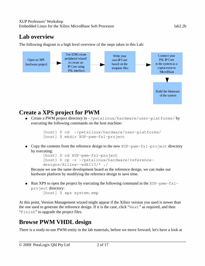
XUP Professors’ WorkshopEmbedded Linux for the Xilinx MicroBlaze Soft Processor lab2.2b
Lab overviewThe following diagram is a high level overview of the steps taken in this Lab:
Create a XPS project for PWM ● Create a PWM project directory in ~/petalinux/hardware/user-platforms/ by
executing the following commands on the host machine:
[host] $ cd ~/petalinux/hardware/user-platforms/[host] $ mkdir XUP-pwm-fsl-project
● Copy the contents from the reference design to the new XUP-pwm-fsl-project directory by executing:
[host] $ cd XUP-pwm-fsl-project [host] $ cp -r ~/petalinux/hardware/reference-designs/Xilinx--edk113/* ./
Because we use the same development board as the reference design, we can make our hardware platform by modifying the reference design to save time.
● Run XPS to open the project by executing the following command in the XUP-pwm-fsl-project directory:
[host] $ xps system.xmp
At this point, Version Management wizard might appear if the Xilinx version you used is newer than the one used to generate the reference design. If it is the case, click “Next” as required, and then “Finish” to upgrade the project files.
Browse PWM VHDL designThere is a ready-to-use PWM entity in the lab materials, before we move forward, let's have a look at
© 2009 PetaLogix Qld Pty Ltd 2 of 17
Open an XPS hardware project
Use EDK createperipheral wizard
to create an IP Core using FSL interface
Write your own IP Core based on the template files
Build the bitstream of the system
Connect your FSL IP Core
to the system as a coprocessor to
MicroBlaze
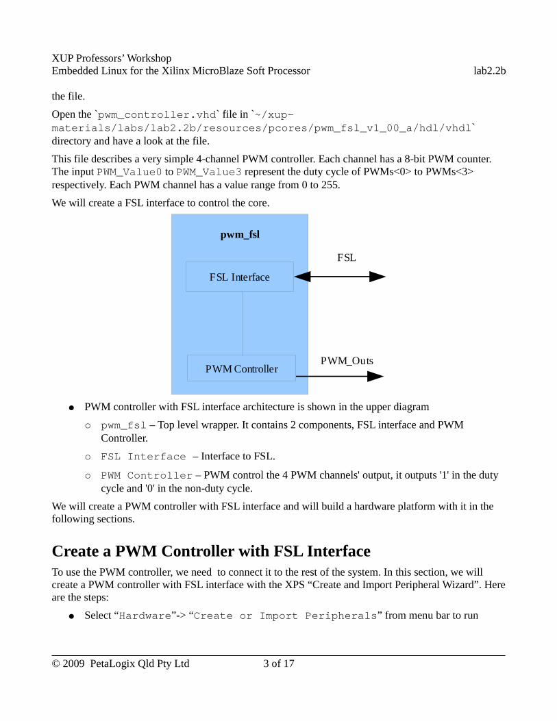
XUP Professors’ WorkshopEmbedded Linux for the Xilinx MicroBlaze Soft Processor lab2.2b
the file.
Open the `pwm_controller.vhd` file in `~/xup-materials/labs/lab2.2b/resources/pcores/pwm_fsl_v1_00_a/hdl/vhdl` directory and have a look at the file.
This file describes a very simple 4-channel PWM controller. Each channel has a 8-bit PWM counter. The input PWM_Value0 to PWM_Value3 represent the duty cycle of PWMs<0> to PWMs<3> respectively. Each PWM channel has a value range from 0 to 255.
We will create a FSL interface to control the core.
● PWM controller with FSL interface architecture is shown in the upper diagram
○ pwm_fsl – Top level wrapper. It contains 2 components, FSL interface and PWM Controller.
○ FSL Interface – Interface to FSL.
○ PWM Controller – PWM control the 4 PWM channels' output, it outputs '1' in the duty cycle and '0' in the non-duty cycle.
We will create a PWM controller with FSL interface and will build a hardware platform with it in the following sections.
Create a PWM Controller with FSL InterfaceTo use the PWM controller, we need to connect it to the rest of the system. In this section, we will create a PWM controller with FSL interface with the XPS “Create and Import Peripheral Wizard”. Here are the steps:
● Select “Hardware”-> “Create or Import Peripherals” from menu bar to run
© 2009 PetaLogix Qld Pty Ltd 3 of 17
pwm_fsl
FSL Interface
PWM Controller
FSL
PWM_Outs
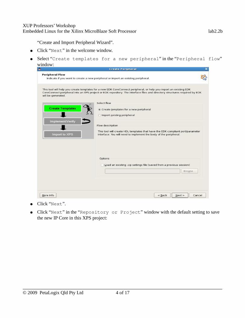
XUP Professors’ WorkshopEmbedded Linux for the Xilinx MicroBlaze Soft Processor lab2.2b
“Create and Import Peripheral Wizard”.
● Click “Next” in the welcome window.
● Select “Create templates for a new peripheral” in the “Peripheral flow” window:
● Click “Next”.
● Click “Next” in the “Repository or Project” window with the default setting to save the new IP Core in this XPS project:
© 2009 PetaLogix Qld Pty Ltd 4 of 17
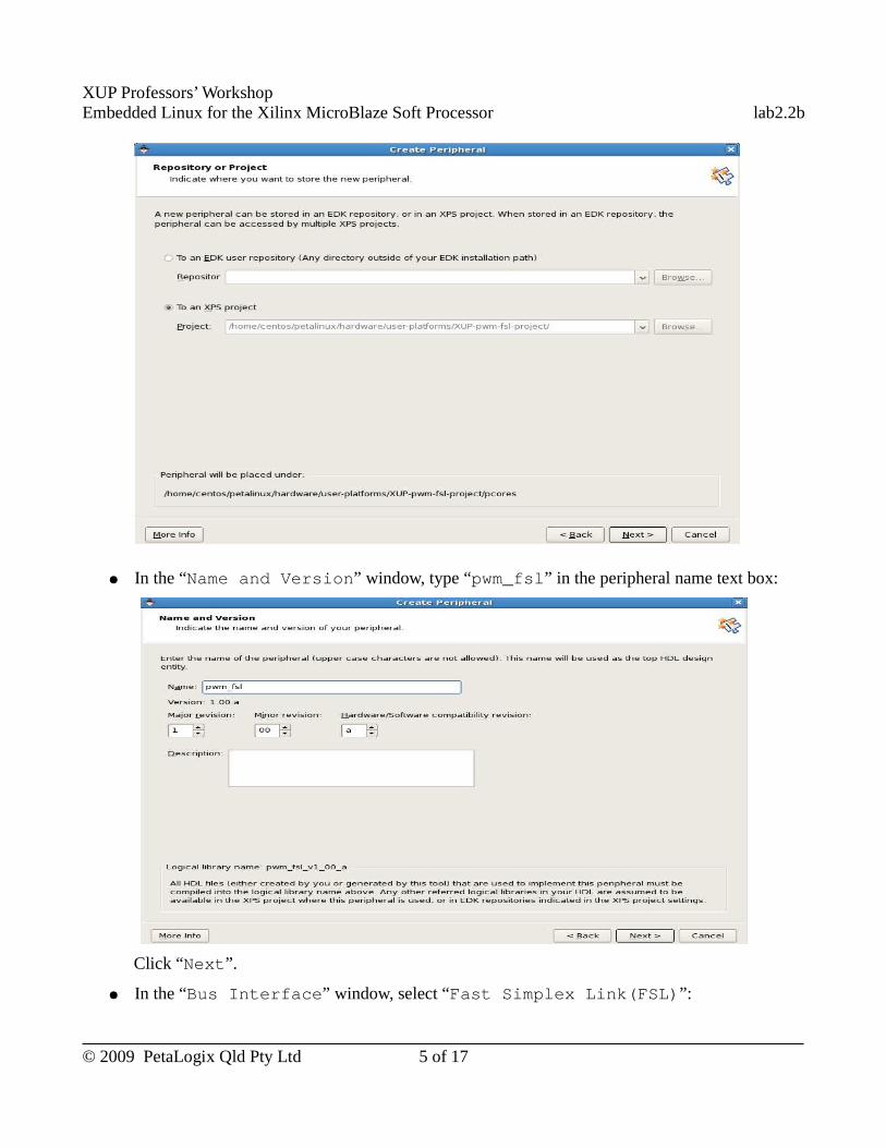
XUP Professors’ WorkshopEmbedded Linux for the Xilinx MicroBlaze Soft Processor lab2.2b
● In the “Name and Version” window, type “pwm_fsl” in the peripheral name text box:
Click “Next”.
● In the “Bus Interface” window, select “Fast Simplex Link(FSL)”:
© 2009 PetaLogix Qld Pty Ltd 5 of 17
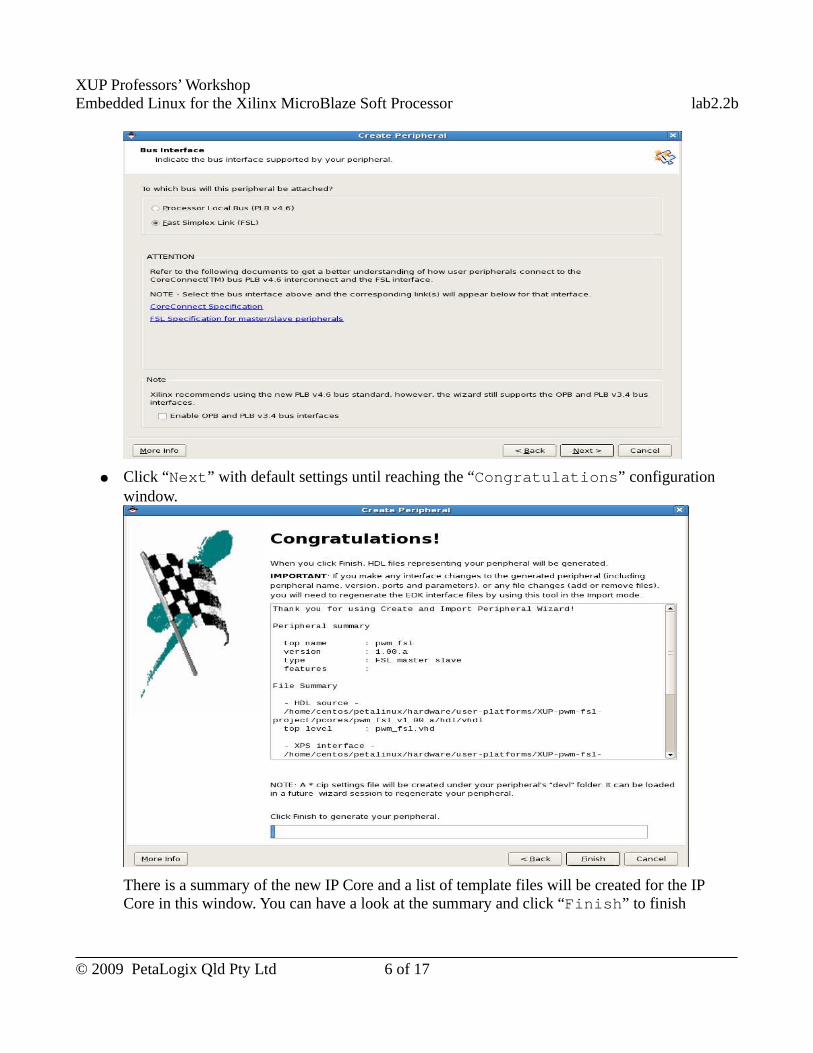
XUP Professors’ WorkshopEmbedded Linux for the Xilinx MicroBlaze Soft Processor lab2.2b
● Click “Next” with default settings until reaching the “Congratulations” configuration window.
There is a summary of the new IP Core and a list of template files will be created for the IP Core in this window. You can have a look at the summary and click “Finish” to finish
© 2009 PetaLogix Qld Pty Ltd 6 of 17
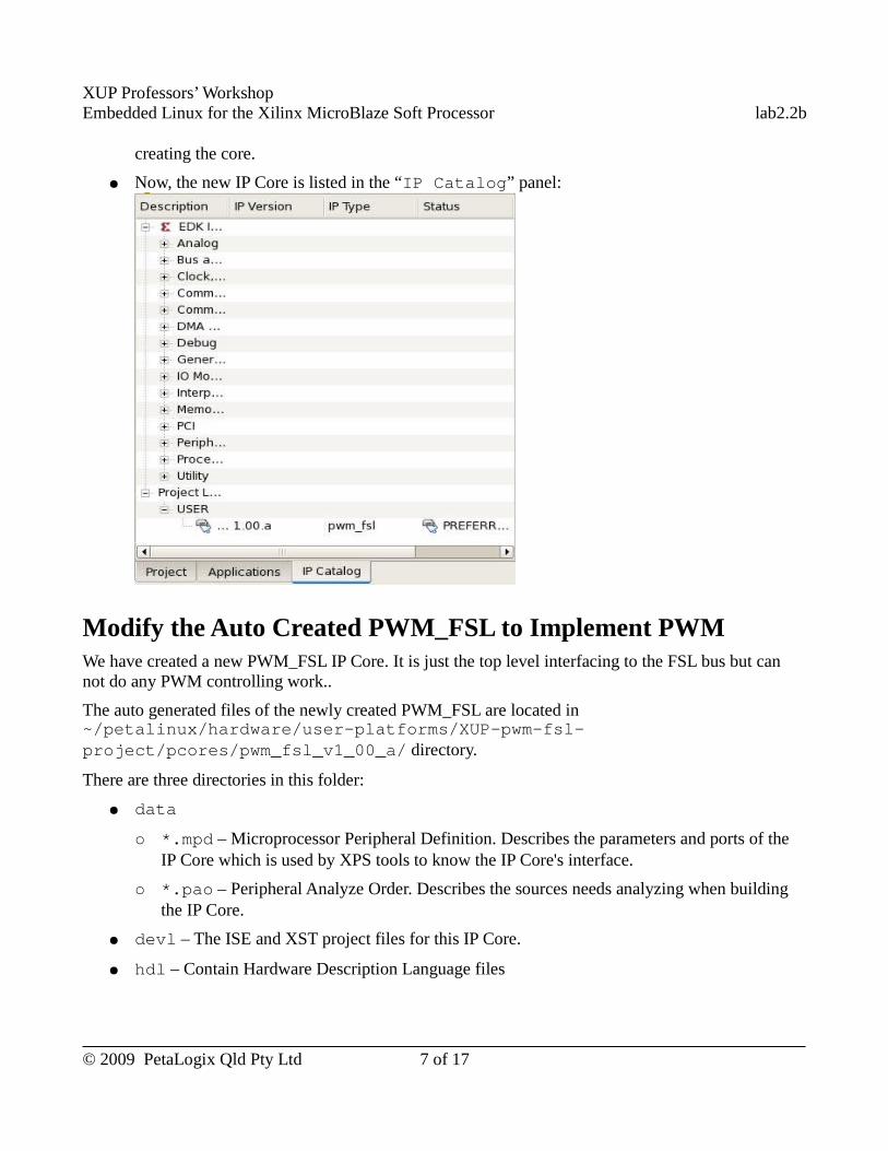
XUP Professors’ WorkshopEmbedded Linux for the Xilinx MicroBlaze Soft Processor lab2.2b
creating the core.
● Now, the new IP Core is listed in the “IP Catalog” panel:
Modify the Auto Created PWM_FSL to Implement PWMWe have created a new PWM_FSL IP Core. It is just the top level interfacing to the FSL bus but can not do any PWM controlling work..
The auto generated files of the newly created PWM_FSL are located in ~/petalinux/hardware/user-platforms/XUP-pwm-fsl-project/pcores/pwm_fsl_v1_00_a/ directory.
There are three directories in this folder:
● data
○ *.mpd – Microprocessor Peripheral Definition. Describes the parameters and ports of the IP Core which is used by XPS tools to know the IP Core's interface.
○ *.pao – Peripheral Analyze Order. Describes the sources needs analyzing when building the IP Core.
● devl – The ISE and XST project files for this IP Core.
● hdl – Contain Hardware Description Language files
© 2009 PetaLogix Qld Pty Ltd 7 of 17
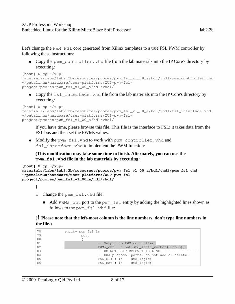
XUP Professors’ WorkshopEmbedded Linux for the Xilinx MicroBlaze Soft Processor lab2.2b
Let's change the PWM_FSL core generated from Xilinx templates to a true FSL PWM controller by following these instructions:
● Copy the pwm_controller.vhd file from the lab materials into the IP Core's directory by executing:
[host] $ cp ~/xup-materials/labs/lab2.2b/resources/pcores/pwm_fsl_v1_00_a/hdl/vhdl/pwm_controller.vhd ~/petalinux/hardware/user-platforms/XUP-pwm-fsl-project/pcores/pwm_fsl_v1_00_a/hdl/vhdl/
● Copy the fsl_interface.vhd file from the lab materials into the IP Core's directory by executing:
[host] $ cp ~/xup-materials/labs/lab2.2b/resources/pcores/pwm_fsl_v1_00_a/hdl/vhdl/fsl_interface.vhd ~/petalinux/hardware/user-platforms/XUP-pwm-fsl-project/pcores/pwm_fsl_v1_00_a/hdl/vhdl/
If you have time, please browse this file. This file is the interface to FSL; it takes data from the FSL bus and then set the PWMs values.
● Modify the pwm_fsl.vhd to work with pwm_controller.vhd and fsl_interface.vhd to implement the PWM function:
(This modification may take some time to finish. Alternately, you can use the pwm_fsl.vhd file in the lab materials by executing:
[host] $ cp ~/xup-materials/labs/lab2.2b/resources/pcores/pwm_fsl_v1_00_a/hdl/vhdl/pwm_fsl.vhd ~/petalinux/hardware/user-platforms/XUP-pwm-fsl-project/pcores/pwm_fsl_v1_00_a/hdl/vhdl/
)
○ Change the pwm_fsl.vhd file:
■ Add PWMs_out port to the pwm_fsl entity by adding the highlighted lines shown as follows to the pwm_fsl.vhd file:
(! Please note that the left-most column is the line numbers, don't type line numbers in the file.)
78 entity pwm_fsl is 79 port 80 ( 81 -- Output to PWM controller 82 PWMs_out : out std_logic_vector(0 to 3); 83 -- DO NOT EDIT BELOW THIS LINE ----------------- 84 -- Bus protocol ports, do not add or delete. 85 FSL_Clk : in std_logic; 86 FSL_Rst : in std_logic;
© 2009 PetaLogix Qld Pty Ltd 8 of 17
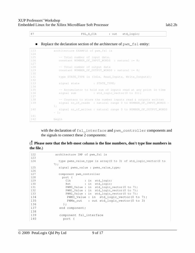
XUP Professors’ WorkshopEmbedded Linux for the Xilinx MicroBlaze Soft Processor lab2.2b
87 FSL_S_Clk : out std_logic;
■ Replace the declaration section of the architecture of pwm_fsl entity:
123 architecture EXAMPLE of pwm_fsl is 124125 -- Total number of input data. 126 constant NUMBER_OF_INPUT_WORDS : natural := 8; 127128 -- Total number of output data 129 constant NUMBER_OF_OUTPUT_WORDS : natural := 8; 130131 type STATE_TYPE is (Idle, Read_Inputs, Write_Outputs); 132133 signal state : STATE_TYPE; 134135 -- Accumulator to hold sum of inputs read at any point in time 136 signal sum : std_logic_vector(0 to 31); 137138 -- Counters to store the number inputs read & outputs written 139 signal nr_of_reads : natural range 0 to NUMBER_OF_INPUT_WORDS -
1; 140 signal nr_of_writes : natural range 0 to NUMBER_OF_OUTPUT_WORDS
- 1; 141142 begin
with the declaration of fsl_interface and pwm_controller components and the signals to connect these 2 components:
(! Please note that the left-most column is the line numbers, don't type line numbers in the file.)
122 architecture IMP of pwm_fsl is 123 124 type pwms_value_type is array(0 to 3) of std_logic_vector(0 to
7); 125 signal pwms_value : pwms_value_type; 126 127 component pwm_controller 128 port ( 129 Clk : in std_logic; 130 Rst : in std_logic; 131 PWM0_Value : in std_logic_vector(0 to 7); 132 PWM1_Value : in std_logic_vector(0 to 7); 133 PWM2_Value : in std_logic_vector(0 to 7); 134 PWM3_Value : in std_logic_vector(0 to 7); 135 PWMs_out : out std_logic_vector(0 to 3) 136 ); 137 end component; 138 139 component fsl_interface 140 port (
© 2009 PetaLogix Qld Pty Ltd 9 of 17
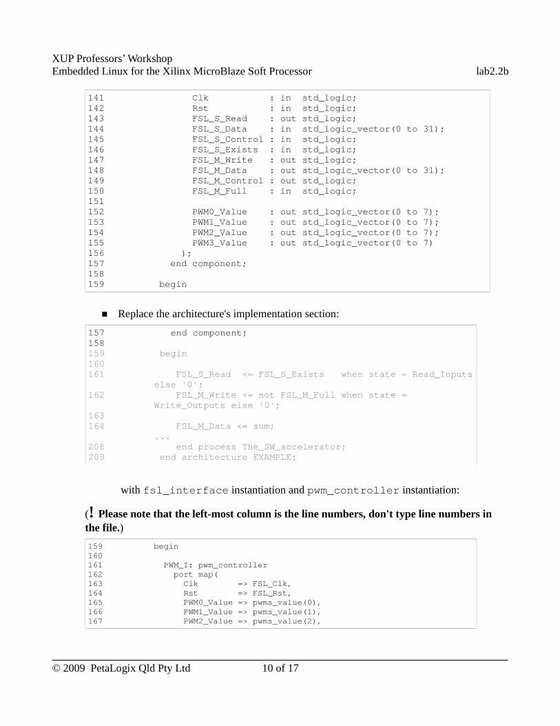
XUP Professors’ WorkshopEmbedded Linux for the Xilinx MicroBlaze Soft Processor lab2.2b
141 Clk : in std_logic; 142 Rst : in std_logic; 143 FSL_S_Read : out std_logic; 144 FSL_S_Data : in std_logic_vector(0 to 31); 145 FSL_S_Control : in std_logic; 146 FSL_S_Exists : in std_logic; 147 FSL_M_Write : out std_logic; 148 FSL_M_Data : out std_logic_vector(0 to 31); 149 FSL_M_Control : out std_logic; 150 FSL_M_Full : in std_logic; 151 152 PWM0_Value : out std_logic_vector(0 to 7); 153 PWM1_Value : out std_logic_vector(0 to 7); 154 PWM2_Value : out std_logic_vector(0 to 7); 155 PWM3_Value : out std_logic_vector(0 to 7) 156 ); 157 end component; 158 159 begin
■ Replace the architecture's implementation section:
157 end component; 158 159 begin 160 161 FSL_S_Read <= FSL_S_Exists when state = Read_Inputs
else '0'; 162 FSL_M_Write <= not FSL_M_Full when state =
Write_Outputs else '0'; 163 164 FSL_M_Data <= sum;
...208 end process The_SW_accelerator; 209 end architecture EXAMPLE;
with fsl_interface instantiation and pwm_controller instantiation:
(! Please note that the left-most column is the line numbers, don't type line numbers in the file.)
159 begin 160 161 PWM_I: pwm_controller 162 port map( 163 Clk => FSL_Clk, 164 Rst => FSL_Rst, 165 PWM0_Value => pwms_value(0), 166 PWM1_Value => pwms_value(1), 167 PWM2_Value => pwms_value(2),
© 2009 PetaLogix Qld Pty Ltd 10 of 17
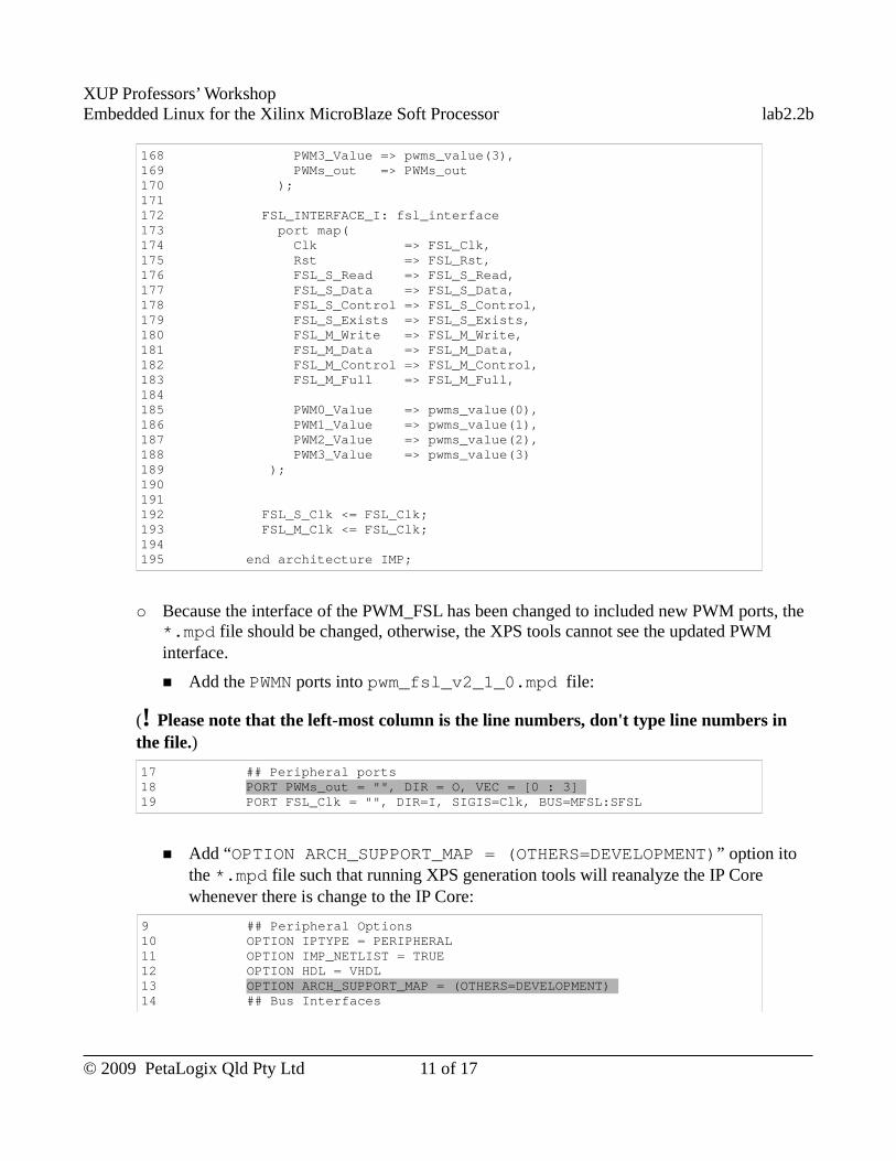
XUP Professors’ WorkshopEmbedded Linux for the Xilinx MicroBlaze Soft Processor lab2.2b
168 PWM3_Value => pwms_value(3), 169 PWMs_out => PWMs_out 170 ); 171 172 FSL_INTERFACE_I: fsl_interface 173 port map( 174 Clk => FSL_Clk, 175 Rst => FSL_Rst, 176 FSL_S_Read => FSL_S_Read, 177 FSL_S_Data => FSL_S_Data, 178 FSL_S_Control => FSL_S_Control, 179 FSL_S_Exists => FSL_S_Exists, 180 FSL_M_Write => FSL_M_Write, 181 FSL_M_Data => FSL_M_Data, 182 FSL_M_Control => FSL_M_Control, 183 FSL_M_Full => FSL_M_Full, 184185 PWM0_Value => pwms_value(0), 186 PWM1_Value => pwms_value(1), 187 PWM2_Value => pwms_value(2), 188 PWM3_Value => pwms_value(3) 189 ); 190 191192 FSL_S_Clk <= FSL_Clk; 193 FSL_M_Clk <= FSL_Clk; 194195 end architecture IMP;
○ Because the interface of the PWM_FSL has been changed to included new PWM ports, the *.mpd file should be changed, otherwise, the XPS tools cannot see the updated PWM interface.
■ Add the PWMN ports into pwm_fsl_v2_1_0.mpd file:
(! Please note that the left-most column is the line numbers, don't type line numbers in the file.)
17 ## Peripheral ports 18 PORT PWMs_out = "", DIR = O, VEC = [0 : 3] 19 PORT FSL_Clk = "", DIR=I, SIGIS=Clk, BUS=MFSL:SFSL
■ Add “OPTION ARCH_SUPPORT_MAP = (OTHERS=DEVELOPMENT)” option ito the *.mpd file such that running XPS generation tools will reanalyze the IP Core whenever there is change to the IP Core:
9 ## Peripheral Options 10 OPTION IPTYPE = PERIPHERAL 11 OPTION IMP_NETLIST = TRUE 12 OPTION HDL = VHDL 13 OPTION ARCH_SUPPORT_MAP = (OTHERS=DEVELOPMENT) 14 ## Bus Interfaces
© 2009 PetaLogix Qld Pty Ltd 11 of 17
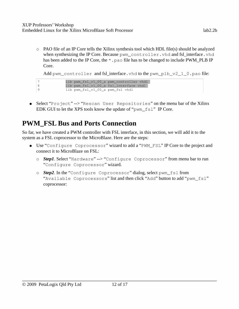
XUP Professors’ WorkshopEmbedded Linux for the Xilinx MicroBlaze Soft Processor lab2.2b
○ PAO file of an IP Core tells the Xilinx synthesis tool which HDL file(s) should be analyzed when synthesizing the IP Core. Because pwm_controller.vhd and fsl_interface.vhd has been added to the IP Core, the *.pao file has to be changed to include PWM_PLB IP Core.
Add pwm_controller and fsl_interface.vhd to the pwm_plb_v2_1_0.pao file:
7 lib pwm_fsl_v1_00_a pwm_controller vhdl 8 lib pwm_fsl_v1_00_a fsl_interface vhdl 9 lib pwm_fsl_v1_00_a pwm_fsl vhdl
● Select “Project” --> “Rescan User Repositories” on the menu bar of the Xilinx EDK GUI to let the XPS tools know the update of “pwm_fsl” IP Core.
PWM_FSL Bus and Ports ConnectionSo far, we have created a PWM controller with FSL interface, in this section, we will add it to the system as a FSL coprocessor to the MicroBlaze. Here are the steps:
● Use “Configure Coprocessor” wizard to add a “PWM_FSL” IP Core to the project and connect it to MicroBlaze on FSL:
○ Step1. Select “Hardware” --> “Configure Coprocessor” from menu bar to run “Configure Coprocessor” wizard.
○ Step2. In the “Configure Coprocessor” dialog, select pwm_fsl from “Available Coprocessors” list and then click “Add” button to add “pwm_fsl” coprocessor:
© 2009 PetaLogix Qld Pty Ltd 12 of 17
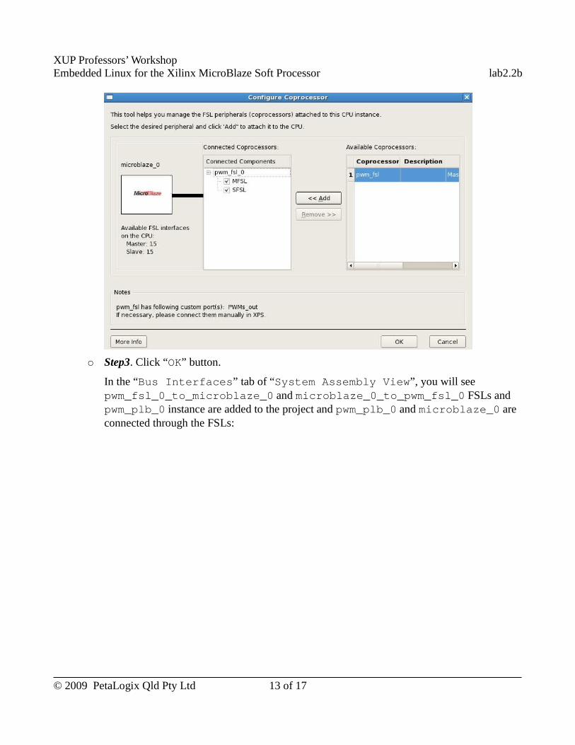
XUP Professors’ WorkshopEmbedded Linux for the Xilinx MicroBlaze Soft Processor lab2.2b
○ Step3. Click “OK” button.
In the “Bus Interfaces” tab of “System Assembly View”, you will see pwm_fsl_0_to_microblaze_0 and microblaze_0_to_pwm_fsl_0 FSLs and pwm_plb_0 instance are added to the project and pwm_plb_0 and microblaze_0 are connected through the FSLs:
© 2009 PetaLogix Qld Pty Ltd 13 of 17
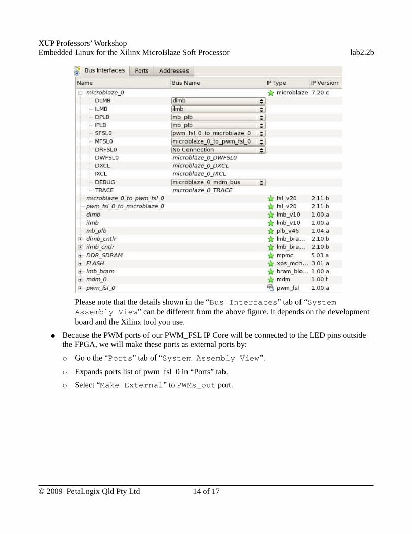
XUP Professors’ WorkshopEmbedded Linux for the Xilinx MicroBlaze Soft Processor lab2.2b
Please note that the details shown in the “Bus Interfaces” tab of “System Assembly View” can be different from the above figure. It depends on the development board and the Xilinx tool you use.
● Because the PWM ports of our PWM_FSL IP Core will be connected to the LED pins outside the FPGA, we will make these ports as external ports by:
○ Go o the “Ports” tab of “System Assembly View”.
○ Expands ports list of pwm_fsl_0 in “Ports” tab.
○ Select “Make External” to PWMs_out port.
© 2009 PetaLogix Qld Pty Ltd 14 of 17
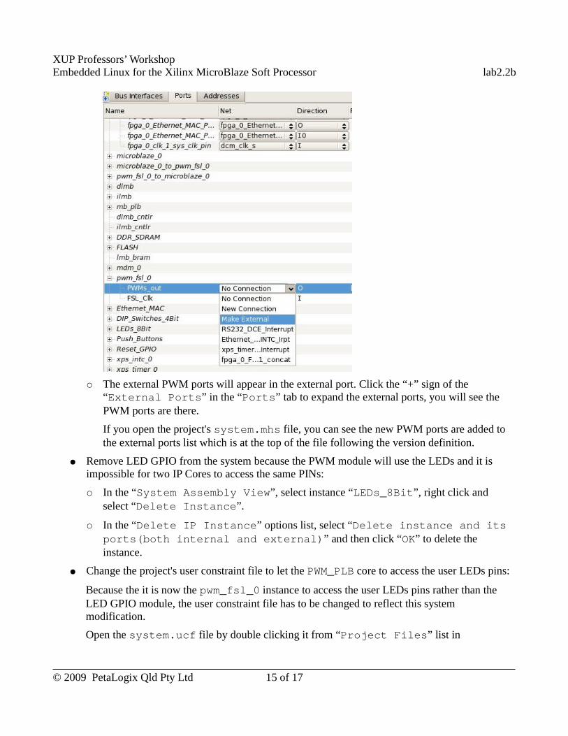
XUP Professors’ WorkshopEmbedded Linux for the Xilinx MicroBlaze Soft Processor lab2.2b
○ The external PWM ports will appear in the external port. Click the “+” sign of the “External Ports” in the “Ports” tab to expand the external ports, you will see the PWM ports are there.
If you open the project's system.mhs file, you can see the new PWM ports are added to the external ports list which is at the top of the file following the version definition.
● Remove LED GPIO from the system because the PWM module will use the LEDs and it is impossible for two IP Cores to access the same PINs:
○ In the “System Assembly View”, select instance “LEDs_8Bit”, right click and select “Delete Instance”.
○ In the “Delete IP Instance” options list, select “Delete instance and its ports(both internal and external)” and then click “OK” to delete the instance.
● Change the project's user constraint file to let the PWM_PLB core to access the user LEDs pins:
Because the it is now the pwm_fsl_0 instance to access the user LEDs pins rather than the LED GPIO module, the user constraint file has to be changed to reflect this system modification.
Open the system.ucf file by double clicking it from “Project Files” list in
© 2009 PetaLogix Qld Pty Ltd 15 of 17
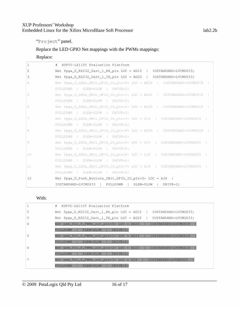
XUP Professors’ WorkshopEmbedded Linux for the Xilinx MicroBlaze Soft Processor lab2.2b
“Project” panel.
Replace the LED GPIO Net mappings with the PWMs mappings:
Replace:
1 # XUPV5-LX110T Evaluation Platform
2 Net fpga_0_RS232_Uart_1_RX_pin LOC = AG15 | IOSTANDARD=LVCMOS33;
3 Net fpga_0_RS232_Uart_1_TX_pin LOC = AG20 | IOSTANDARD=LVCMOS33;
4 Net fpga_0_LEDs_8Bit_GPIO_IO_pin<0> LOC = AE24 | IOSTANDARD=LVCMOS18 |
PULLDOWN | SLEW=SLOW | DRIVE=2;
5 Net fpga_0_LEDs_8Bit_GPIO_IO_pin<1> LOC = AD24 | IOSTANDARD=LVCMOS18 |
PULLDOWN | SLEW=SLOW | DRIVE=2;
6 Net fpga_0_LEDs_8Bit_GPIO_IO_pin<2> LOC = AD25 | IOSTANDARD=LVCMOS18 |
PULLDOWN | SLEW=SLOW | DRIVE=2;
7 Net fpga_0_LEDs_8Bit_GPIO_IO_pin<3> LOC = G16 | IOSTANDARD=LVCMOS25 |
PULLDOWN | SLEW=SLOW | DRIVE=2;
8 Net fpga_0_LEDs_8Bit_GPIO_IO_pin<4> LOC = AD26 | IOSTANDARD=LVCMOS18 |
PULLDOWN | SLEW=SLOW | DRIVE=2;
9 Net fpga_0_LEDs_8Bit_GPIO_IO_pin<5> LOC = G15 | IOSTANDARD=LVCMOS25 |
PULLDOWN | SLEW=SLOW | DRIVE=2;
10 Net fpga_0_LEDs_8Bit_GPIO_IO_pin<6> LOC = L18 | IOSTANDARD=LVCMOS25 |
PULLDOWN | SLEW=SLOW | DRIVE=2;
11 Net fpga_0_LEDs_8Bit_GPIO_IO_pin<7> LOC = H18 | IOSTANDARD=LVCMOS25 |
PULLDOWN | SLEW=SLOW | DRIVE=2;
12 Net fpga_0_Push_Buttons_5Bit_GPIO_IO_pin<0> LOC = AJ6 |
IOSTANDARD=LVCMOS33 | PULLDOWN | SLEW=SLOW | DRIVE=2;
With:
1 # XUPV5-LX110T Evaluation Platform
2 Net fpga_0_RS232_Uart_1_RX_pin LOC = AG15 | IOSTANDARD=LVCMOS33;
3 Net fpga_0_RS232_Uart_1_TX_pin LOC = AG20 | IOSTANDARD=LVCMOS33;
4 Net pwm_fsl_0_PWMs_out_pin<0> LOC = AE24 | IOSTANDARD=LVCMOS18 |
PULLDOWN | SLEW=SLOW | DRIVE=2;
5 Net pwm_fsl_0_PWMs_out_pin<1> LOC = AD24 | IOSTANDARD=LVCMOS18 |
PULLDOWN | SLEW=SLOW | DRIVE=2;
6 Net pwm_fsl_0_PWMs_out_pin<2> LOC = AD25 | IOSTANDARD=LVCMOS18 |
PULLDOWN | SLEW=SLOW | DRIVE=2;
7 Net pwm_fsl_0_PWMs_out_pin<3> LOC = G16 | IOSTANDARD=LVCMOS25 |
PULLDOWN | SLEW=SLOW | DRIVE=2;
© 2009 PetaLogix Qld Pty Ltd 16 of 17
XUP Professors’ WorkshopEmbedded Linux for the Xilinx MicroBlaze Soft Processor lab2.2b
8 Net fpga_0_Push_Buttons_5Bit_GPIO_IO_pin<0> LOC = AJ6 |
IOSTANDARD=LVCMOS33 | PULLDOWN | SLEW=SLOW | DRIVE=2;
Build BitstreamBuild the bitstream as we have learned in Lab 2.1 using Xilinx EDK GUI. If it is your first lab, please refer to section “Build the Hardware Bitstream” section in the Lab 2.1 manual.
We leave the PWM_FSL test to next lab.
Use Completed ResourceThe completed Linux image for this lab is available in ~/xup_materials/labs/lab2.2b/completed/. If you are stuck in any problem in the lab, you are welcome to use the completed resource. Here is the instruction on how to use the completed resource:
● Copy the completed hardware project to PetaLinux tree by executing:
[host] $ ~/xup_materials/complete_lab 2.2b
● Download the bitstream to the board by executing:
[host] $ cd ~/petalinux/hardware/user-platforms/XUP-pwm-fsl-project
[host] $ impact -batch etc/download.cmd
This command will download the bitstream implementation/download.bit to the board. (iMPACT is the Xilinx device configuration tool.)
OutcomesAt the completion of this lab you should
● know how to create a custom hardware IP Core with XPS tool ● know how to add a and modify an FSL-based coprocessor using the Xilinx tools● know how to build bitstream from XPS GUI● know the common bus interface – FSL
Document VersionDoc ID: lab2_2bBuild: xupv5-edk113-7425Date: 2010-01-21
© 2009 PetaLogix Qld Pty Ltd 17 of 17
XUP Professors’ WorkshopEmbedded Linux for the Xilinx MicroBlaze Soft Processor lab2.3a
Lab 2.3a – Custom Driver Development
-- PLB Device
RationaleUsually, after we created a new IP Core in hardware platform, we should create a device driver for it so that the system is able to access the new hardware through its driver.
There are different device models provided by Embedded Linux. Platform devices are devices that typically appear as autonomous entities in the system. What they usually have in common is direct addressing from a CPU bus such as Processor Local Bus (PLB).
Objectives● Design a driver for the plb_pwm IP Core created in the previous lab.● Write a simple application to test the driver.
IntroductionIn the previous Lab 2.2a, we have created a PWM controller with PLB interface. In this lab, we are going to create an Embedded Linux driver for the PWM with PLB interface IP Core and an application to test it.
TimeThis session will run for approximately 60 minutes.
PreparationIf this is the first lab you are doing then please refer to sections “Before You Start” of Lab 1.1 document for necessary preparatory information on how to setup the hardware environment.
© 2009 PetaLogix Qld Pty Ltd 1 of 12
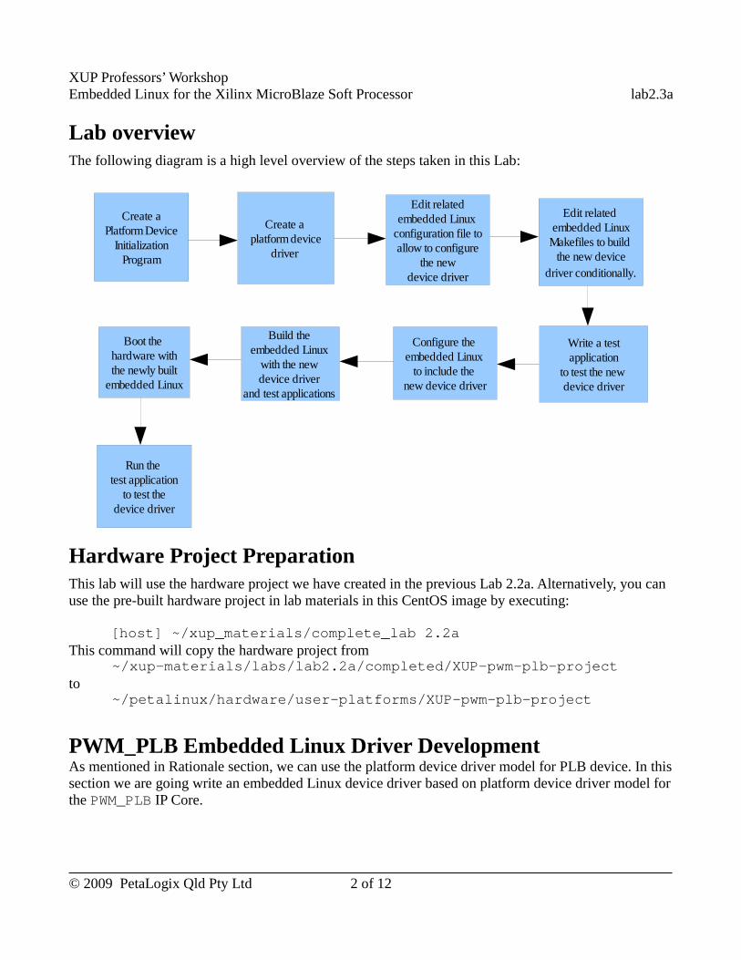
XUP Professors’ WorkshopEmbedded Linux for the Xilinx MicroBlaze Soft Processor lab2.3a
Lab overviewThe following diagram is a high level overview of the steps taken in this Lab:
Hardware Project Preparation This lab will use the hardware project we have created in the previous Lab 2.2a. Alternatively, you can use the pre-built hardware project in lab materials in this CentOS image by executing:
[host] ~/xup_materials/complete_lab 2.2aThis command will copy the hardware project from
~/xup-materials/labs/lab2.2a/completed/XUP-pwm-plb-projectto
~/petalinux/hardware/user-platforms/XUP-pwm-plb-project
PWM_PLB Embedded Linux Driver DevelopmentAs mentioned in Rationale section, we can use the platform device driver model for PLB device. In this section we are going write an embedded Linux device driver based on platform device driver model for the PWM_PLB IP Core.
© 2009 PetaLogix Qld Pty Ltd 2 of 12
Create aPlatform Device
Initialization Program
Create a platform device
driver
Edit relatedembedded Linux
configuration file toallow to configure
the new device driver
Edit related embedded Linux
Makefiles to build the new device
driver conditionally.
Build the embedded Linux
with the new device driver
and test applications
Configure the embedded Linux
to include the new device driver
Write a test application
to test the new device driver
Boot the hardware with the newly built
embedded Linux
Run the test application
to test the device driver
XUP Professors’ WorkshopEmbedded Linux for the Xilinx MicroBlaze Soft Processor lab2.3a
Get Addressable Resource of PWM_PLB
In order to access a platform device, the Linux system needs to know where a platform device is. Thus, first of all, we need to write a initialization program for the Embedded Linux system to know what is the accessible resource of the PWM_PLB device at the early stage of the embedded Linux system startup.
● Create a PWM_PLB device initialization program by following these steps:
○ Go to ~/petalinux/software/petalinux-dist/linux-2.6.x/arch/microblaze/platform directory by executing the following command on the host machine:
[host] $ cd ~/petalinux/software/petalinux-dist/linux-2.6.x/arch/microblaze/platform
There are platforms directories in this folder. Our pwm_plb device is independent to any special platform, thus, we will put the program in the common directory.
○ Go to the common directory by executing:
[host] $ cd common
There is a ready-to-use program to get resources of PWM_PLB core in the lab materials. Please copy that program to the common directory by executing:
[host] $ cp ~/xup-materials/labs/lab2.3a/resources/platform/common/petalogix_pwm.c ./
● Browse the petalogix_pwm.c file.
This file has a function “ppm_platform_init()” to get the accessible resource information of PWM_PLB device and register the device.
The line “device_initcall(ppwm_platform_init);” at the end of the file will expose the “ppm_platform_init()” function to the kernel initialization process such that this function will be called when the system is booting.
After the platform device has been registered, the Embedded Linux will try to bind the device with a driver.
Write PWM_PLB Driver
Now, we go to write a driver for the PWM_PLB platform device by following these steps:
● Let's consider the PWM_PLB device driver as a miscellaneous device driver which is a type of char devices. Go to drivers/misc directory by executing:
[host] $ cd ~/petalinux/software/petalinux-
© 2009 PetaLogix Qld Pty Ltd 3 of 12
XUP Professors’ WorkshopEmbedded Linux for the Xilinx MicroBlaze Soft Processor lab2.3a
dist/linux-2.6.x/drivers/misc
● There is a ready-to-use driver file for this device in the lab materials. Please copy that file to thedirectory by executing:
[host] $ cp ~/xup-materials/labs/lab2.3a/resources/drivers/misc/ppwm_adapter.c .
● Have a look at the driver file.
In this ppwm_adapter.c file, it defines the misc device file operations and the platform device operations for the PWM_PLB device.
User accessing the PWM_PLB device is almost the same as accessing a normal file. The driver provides these file access functions: open(), release(), read(), write() and ioctl().
PWM_PLB is a platform device, the driver also defines platform device driver operations such as probe() to allocate system resource for the device and then register it as a miscellaneous device; and remove() to unregister it as miscellaneous device and then delete all the system resource for the device.
A platform device driver has to be registered before it can be used, thus, in the module initialization function--ppwm_init(), it register the PWM platform device driver. Accordingly, in the module exit function--ppwm_cleanup(), it unregister the PWM platform device driver.
● Write a header file for pwm_plb driver's ioctl() function.
The ioctl() function is usually used to write/read a control word or a single data to the device. In the pwm_plb driver, the ioctl() is designed to write/read a single data to/from a specified channel. We need some customized data structure and macros to implement this function. Thus, we need a header file for the customized ioctl().
The header file, ppwm_ioctl.h is already in the lab materials. Please copy that file to ~/petalinux/software/linux-2.6.x-petalogix/include/asm-microblaze by executing:
[host] $ cd ~/petalinux/software/linux-2.6.x-petalogix/include/asm-microblaze
[host] $ cp ~/xup-materials/labs/lab2.3/resources/asm/ppwm_ioctl.h ./
● Browse the ppwm_ioctl.h file.
This header file defines a PWM ioctl data structure, and in/out PWM device ioctl operations macros.
© 2009 PetaLogix Qld Pty Ltd 4 of 12
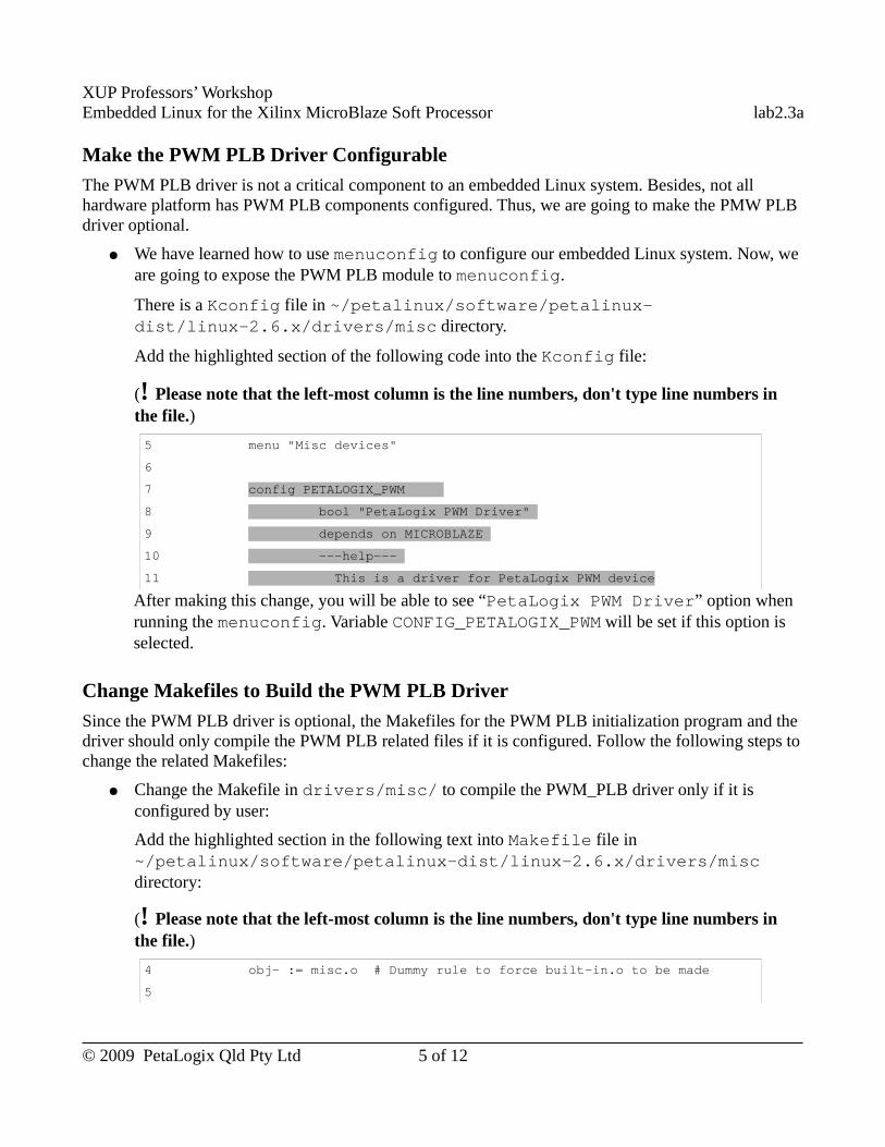
XUP Professors’ WorkshopEmbedded Linux for the Xilinx MicroBlaze Soft Processor lab2.3a
Make the PWM PLB Driver Configurable
The PWM PLB driver is not a critical component to an embedded Linux system. Besides, not all hardware platform has PWM PLB components configured. Thus, we are going to make the PMW PLB driver optional.
● We have learned how to use menuconfig to configure our embedded Linux system. Now, we are going to expose the PWM PLB module to menuconfig.
There is a Kconfig file in ~/petalinux/software/petalinux-dist/linux-2.6.x/drivers/misc directory.
Add the highlighted section of the following code into the Kconfig file:
(! Please note that the left-most column is the line numbers, don't type line numbers in the file.)
5 menu "Misc devices"
6
7 config PETALOGIX_PWM
8 bool "PetaLogix PWM Driver"
9 depends on MICROBLAZE
10 ---help---
11 This is a driver for PetaLogix PWM device
After making this change, you will be able to see “PetaLogix PWM Driver” option when running the menuconfig. Variable CONFIG_PETALOGIX_PWM will be set if this option is selected.
Change Makefiles to Build the PWM PLB Driver
Since the PWM PLB driver is optional, the Makefiles for the PWM PLB initialization program and the driver should only compile the PWM PLB related files if it is configured. Follow the following steps to change the related Makefiles:
● Change the Makefile in drivers/misc/ to compile the PWM_PLB driver only if it is configured by user:
Add the highlighted section in the following text into Makefile file in ~/petalinux/software/petalinux-dist/linux-2.6.x/drivers/misc directory:
(! Please note that the left-most column is the line numbers, don't type line numbers in the file.)
4 obj- := misc.o # Dummy rule to force built-in.o to be made
5
© 2009 PetaLogix Qld Pty Ltd 5 of 12
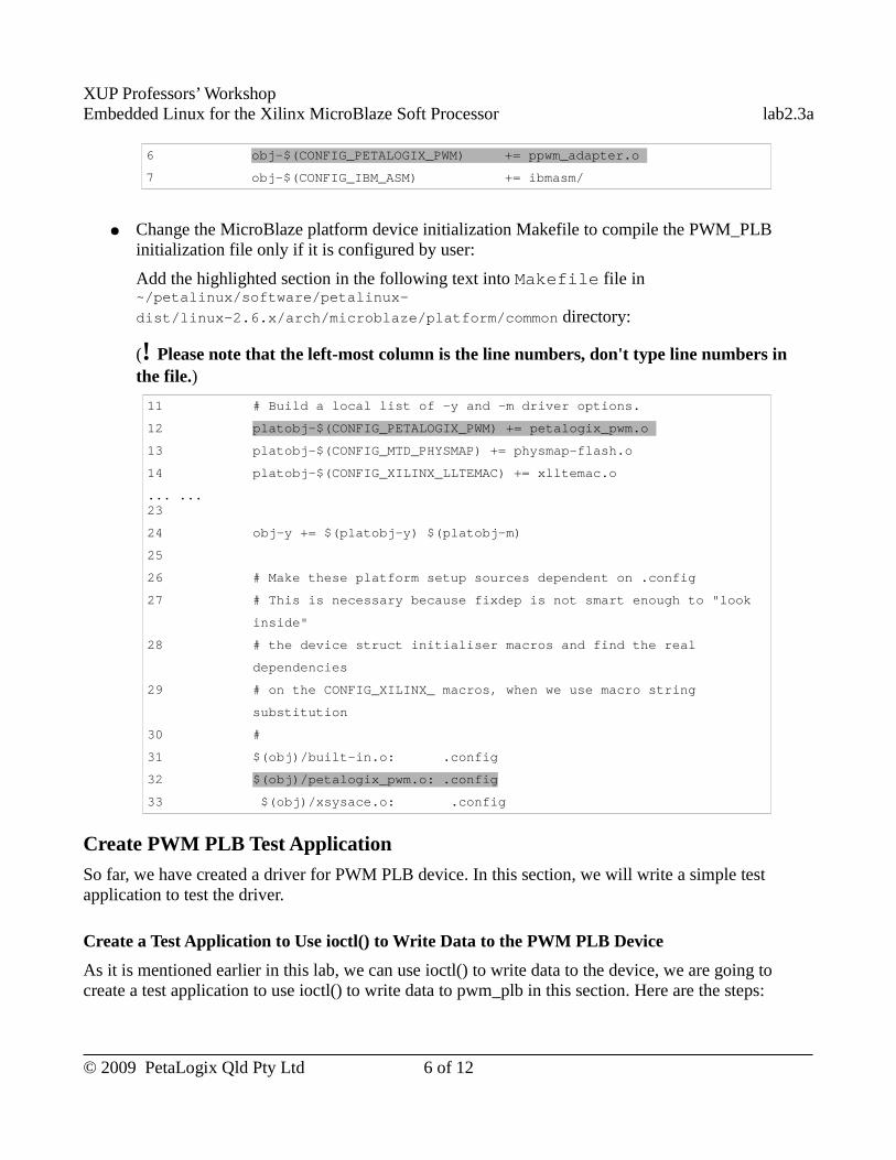
XUP Professors’ WorkshopEmbedded Linux for the Xilinx MicroBlaze Soft Processor lab2.3a
6 obj-$(CONFIG_PETALOGIX_PWM) += ppwm_adapter.o
7 obj-$(CONFIG_IBM_ASM) += ibmasm/
● Change the MicroBlaze platform device initialization Makefile to compile the PWM_PLB initialization file only if it is configured by user:
Add the highlighted section in the following text into Makefile file in ~/petalinux/software/petalinux-
dist/linux-2.6.x/arch/microblaze/platform/common directory:
(! Please note that the left-most column is the line numbers, don't type line numbers in the file.)
11 # Build a local list of -y and -m driver options.
12 platobj-$(CONFIG_PETALOGIX_PWM) += petalogix_pwm.o
13 platobj-$(CONFIG_MTD_PHYSMAP) += physmap-flash.o
14 platobj-$(CONFIG_XILINX_LLTEMAC) += xlltemac.o
... ...23
24 obj-y += $(platobj-y) $(platobj-m)
25
26 # Make these platform setup sources dependent on .config
27 # This is necessary because fixdep is not smart enough to "look
inside"
28 # the device struct initialiser macros and find the real
dependencies
29 # on the CONFIG_XILINX_ macros, when we use macro string
substitution
30 #
31 $(obj)/built-in.o: .config
32 $(obj)/petalogix_pwm.o: .config
33 $(obj)/xsysace.o: .config
Create PWM PLB Test Application
So far, we have created a driver for PWM PLB device. In this section, we will write a simple test application to test the driver.
Create a Test Application to Use ioctl() to Write Data to the PWM PLB Device
As it is mentioned earlier in this lab, we can use ioctl() to write data to the device, we are going to create a test application to use ioctl() to write data to pwm_plb in this section. Here are the steps:
© 2009 PetaLogix Qld Pty Ltd 6 of 12
XUP Professors’ WorkshopEmbedded Linux for the Xilinx MicroBlaze Soft Processor lab2.3a
● Use PetaLogix tool to create a new user application by executing:
[host] $ petalinux-new-app pwm_plb_test_ioctl
● There is a ready-to-use PWM PLB ioctl test application in the lab materials. Copy those test application files to the newly created pwm_plb_test_ioctl directory by executing:
[host] $ cd ~/petalinux/software/user-apps/pwm_plb_test_ioctl
[host] $ cp ~/xup-materials/labs/lab2.3a/resources/user-apps/pwm_plb_test_ioctl/* ./
● Browse the files in the pwm_plb_test_ioctl directory. Here is a brief description of these files:
○ Makefile – Build the pwm_plb_test_ioctl application and create a device file ppwm0 to /dev/ directory in the root file system.
○ pwm_plb_test_ioctl.c – A simple test program to get input from 4 buttons and send PWM value to PWM_PLB driver. Each button corresponds to one LED. The PWM value will increase by “10” from 0 to 255 whenever the corresponding button is pressed; when the value saturates, it will drop to “0” or “5”; and then it will increase by “10” again when the button is pressed.
Note: The file name of the button's GPIO device is hard coded ( #define BUTTON_FILE "/dev/gpio1")in the source files. Please make sure it is correct. The sequence of the GPIOs listed in “/dev” directory is the same as the alphabet sequence of the hardware instance names of the GPIOs.
Create PWM PLB Test Application to Use write()
We have created a test application to test the ioctl() function of the driver, in this section, we will create an application to test the write() function of the pwm_plb driver. Here are the steps:
● Use PetaLogix tool to create a new user application
[host] $ petalinux-new-app pwm_plb_test_write
● There is a ready-to-use PWM PLB write() test application in the lab materials. Copy those test application files to the newly created pwm_plb_test_write directory by executing:
[host] $ cd ~/petalinux/software/user-apps/pwm_plb_test_write
[host] $ cp ~/xup-materials/labs/lab2.3a/resources/user-apps/pwm_plb_test_write/* ./
● Browse the files in the pwm_plb_test_write directory. Here is a brief description of these files:
○ Makefile – Build the pwm_plb_test_write application and create a device file ppwm0 to /dev/ directory in the root file system.
© 2009 PetaLogix Qld Pty Ltd 7 of 12
XUP Professors’ WorkshopEmbedded Linux for the Xilinx MicroBlaze Soft Processor lab2.3a
○ pwm_plb_test_write.c – A simple test program to implement the same function as pwm_plb_test_ioctl.c. But it uses write() to write the PWM_PLB core instead of ioctl().
Create PWM PLB Test Application to Read Data from the Device
We have created test applications to write data to the PWM PLB device. Now we are going to write a test application to read the PWM value from it. Here are the steps:
There is an already-done test application in `~/xup-materials/labs/lab2.3/resources/user-apps/pwm_plb_testr`.
● Use PetaLogix tool to create a new user application
[host] $ petalinux-new-app pwm_plb_testr
● There is a ready-to-use read PWM PLB test application in the lab materials. Copy those test application files to the newly created pwm_plb_testr directory by executing:
[host] $ cd ~/petalinux/software/user-apps/pwm_plb_testr
[host] $ cp ~/xup-materials/labs/lab2.3a/resources/user-apps/pwm_plb_testr/* ./
● Browse the files in the pwm_plb_testr directory. Here is a brief description of these files:
○ Makefile – Build the pwm_plb_testr applicationand create a device file ppwm0 to /dev/ directory in the root file system.
○ pwm_plb_testr.c – A simple test program to read PWM values from PWM_PLB with ioctl() and read().
Build Embedded LinuxSo far, we have created PWM_PLB driver and PWM_PLB test application. In this section, we will build an Embedded Linux image including the PWM PLB driver and the test applications by following these instructions:
● Use menuconfig to select a proper reference platform for the embedded Linux system. Follow these steps:
○ Run menuconfig by executing:
[host] $ cd ~/petalinux/software/petalinux-dist
[host] $ make menuconfig
○ Select the “Vendor/Product Selection --->” sub-menu.
○ Set the vendor to “Xilinx” and product to “-edk113” in the “Vendor/Product
© 2009 PetaLogix Qld Pty Ltd 8 of 12
XUP Professors’ WorkshopEmbedded Linux for the Xilinx MicroBlaze Soft Processor lab2.3a
Selection --->” sub-menu.
○ Select Exit the menuconfig and then save the change.
● Go to the hardware project directory and copy the hardware configuration to PetaLinux by executing:
[host] $ cd ~/petalinux/hardware/user-platforms/XUP-pwm-plb-project
[host] $ petalinux-copy-autoconfig
● Use menuconfig to configure the embedded Linux system to include the PWM PLB driver by following these steps:
○ Run menuconfig by executing:
[host] $ cd ~/petalinux/software/petalinux-dist
[host] $ make menuconfig
○ Select “[*] Customise Kernel Settings” in “Kernel/Library/Defaults Section” sub-menu.
○ Exit and save the configuration.○ When the “Linux Kernel Configuration” menu pop up, select the “Device
Drivers” sub-menu.
○ Select “Misc devices” sub-menu in “Device Drivers” menu.
○ Select “PetaLogix PWM Driver” in “Misc devices” menu:
[*] PetaLogix PWM Driver
© 2009 PetaLogix Qld Pty Ltd 9 of 12
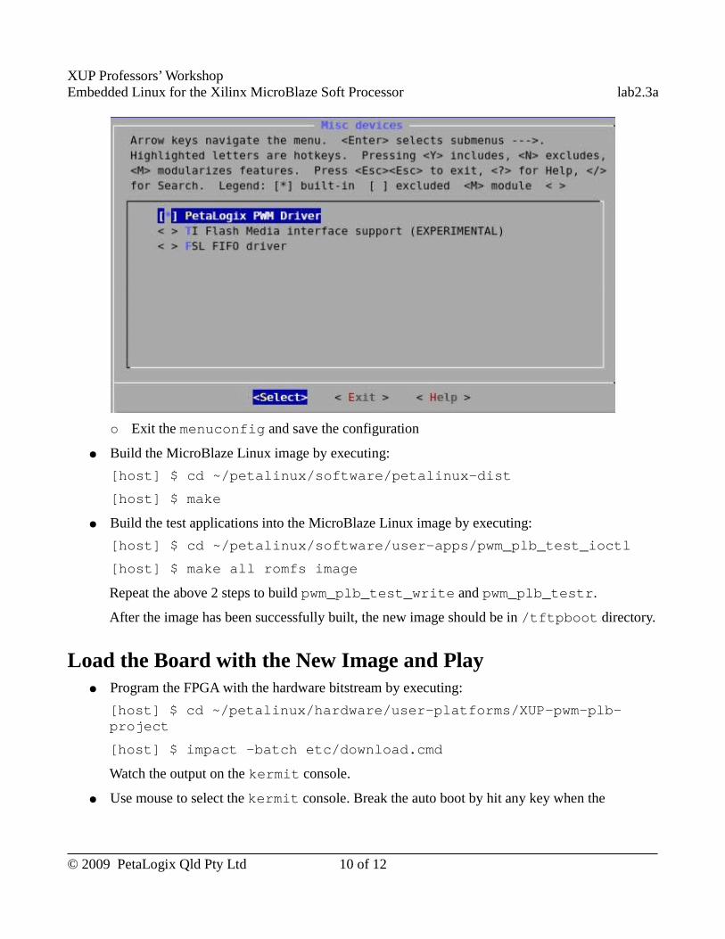
XUP Professors’ WorkshopEmbedded Linux for the Xilinx MicroBlaze Soft Processor lab2.3a
○ Exit the menuconfig and save the configuration
● Build the MicroBlaze Linux image by executing:
[host] $ cd ~/petalinux/software/petalinux-dist
[host] $ make
● Build the test applications into the MicroBlaze Linux image by executing:
[host] $ cd ~/petalinux/software/user-apps/pwm_plb_test_ioctl
[host] $ make all romfs image
Repeat the above 2 steps to build pwm_plb_test_write and pwm_plb_testr.
After the image has been successfully built, the new image should be in /tftpboot directory.
Load the Board with the New Image and Play● Program the FPGA with the hardware bitstream by executing:
[host] $ cd ~/petalinux/hardware/user-platforms/XUP-pwm-plb-project
[host] $ impact -batch etc/download.cmd
Watch the output on the kermit console.
● Use mouse to select the kermit console. Break the auto boot by hit any key when the
© 2009 PetaLogix Qld Pty Ltd 10 of 12
XUP Professors’ WorkshopEmbedded Linux for the Xilinx MicroBlaze Soft Processor lab2.3a
messages similar to the following are shown on the kermit console:
FLASH: 16 MB
ETHERNET: MAC:00:0a:35:00:22:01
Hit any key to stop autoboot: 4
● Download the Embedded Linux image to the board using tftp and boot the system by executing the following command on the kermit console:
U-Boot> run netboot
● Watch the MicroBlaze Linux booting information on the kermit console, you should see the PWM_PLB driver initialization information similar to this:
ppwm0 #0 at 0xC9C00000 mapped to 0xC9C00000 device: 10,128
● Login when the MicroBlaze Linux system is boot.
● Try pwm_plb_test_ioctl by executing the following command on the kermit console:
# pwm_plb_test_ioctl
The following message will be shown on the kermit console:
PWM PLB Test -- ioctl()
Push button N, E, S, W corresponds to GPIO LED 4 ~ 7. When you press the buttons, you will see the brightness change of the GPIO LEDs.
● Try pwm_plb_test_write and press the buttons. The same as running pwm_plb_test_ioctl, you should see the brightness change of the LEDs.
● Try pwm_plb_testr, you will see the current PWM values.
e.g.
# pwm_plb_testr
Read PWM PLB Test
Read PWM PLB -- ioctl()
PWM[0]: 200
PWM[1]: 150
PWM[2]: 130
© 2009 PetaLogix Qld Pty Ltd 11 of 12
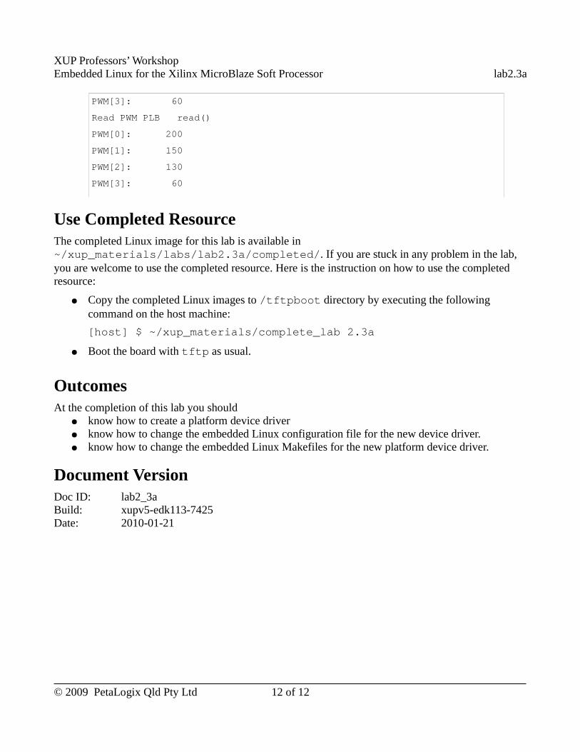
XUP Professors’ WorkshopEmbedded Linux for the Xilinx MicroBlaze Soft Processor lab2.3a
PWM[3]: 60
Read PWM PLB � read()
PWM[0]: 200
PWM[1]: 150
PWM[2]: 130
PWM[3]: 60
Use Completed ResourceThe completed Linux image for this lab is available in ~/xup_materials/labs/lab2.3a/completed/. If you are stuck in any problem in the lab, you are welcome to use the completed resource. Here is the instruction on how to use the completed resource:
● Copy the completed Linux images to /tftpboot directory by executing the following command on the host machine:
[host] $ ~/xup_materials/complete_lab 2.3a
● Boot the board with tftp as usual.
OutcomesAt the completion of this lab you should
● know how to create a platform device driver ● know how to change the embedded Linux configuration file for the new device driver.● know how to change the embedded Linux Makefiles for the new platform device driver.
Document VersionDoc ID: lab2_3aBuild: xupv5-edk113-7425Date: 2010-01-21
© 2009 PetaLogix Qld Pty Ltd 12 of 12
XUP Professors’ WorkshopEmbedded Linux for the Xilinx MicroBlaze Soft Processor lab2.3b
Lab 2.3b – Custom Driver Development
-- FSL Device
RationaleUsually, after we created a new IP Core in hardware platform, we should create a device driver for it so that the system is able to access the new hardware through its driver.
In the previous Lab 2.2b, we have created a PWM FSL IP Core. This IP Core connects to the MicroBlaze on the Fast Simplex Link(FSL) bus. FSL is a commonly used bus to connect the MicroBlaze to its coprocessors. PetaLinux has an existing FSL driver and thus, we can use the PetaLinux FSL driver for our PWM FSL IP Core.
Objectives● Use the existing PetaLinux FSL driver for a newly created FSL hardware device.● Write a simple application to use the PetaLinux FSL driver to test the FSL PWM controller.
IntroductionIn the previous lab2.2b, we have created a PWM controller with FSL interface. We are going to use the existing PetaLinux FSL driver for it and write an test application to test the PWM FSL device.
TimeThis session will run for approximately 60 minutes.
PreparationIf this is the first lab you are doing then please refer to sections “Before You Start” of Lab 1.1 document for necessary preparatory information on how to setup the hardware environment.
© 2009 PetaLogix Qld Pty Ltd 1 of 7
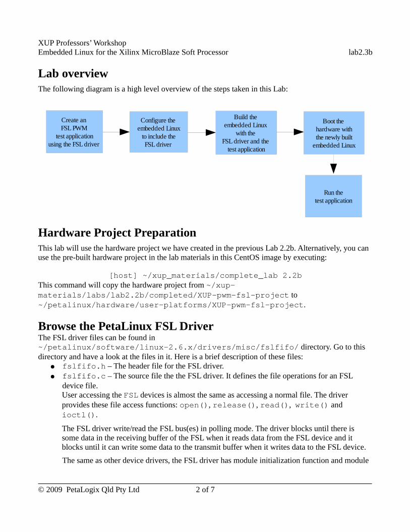
XUP Professors’ WorkshopEmbedded Linux for the Xilinx MicroBlaze Soft Processor lab2.3b
Lab overviewThe following diagram is a high level overview of the steps taken in this Lab:
Hardware Project Preparation This lab will use the hardware project we have created in the previous Lab 2.2b. Alternatively, you can use the pre-built hardware project in the lab materials in this CentOS image by executing:
[host] ~/xup_materials/complete_lab 2.2bThis command will copy the hardware project from ~/xup-materials/labs/lab2.2b/completed/XUP-pwm-fsl-project to ~/petalinux/hardware/user-platforms/XUP-pwm-fsl-project.
Browse the PetaLinux FSL Driver The FSL driver files can be found in ~/petalinux/software/linux-2.6.x/drivers/misc/fslfifo/ directory. Go to this directory and have a look at the files in it. Here is a brief description of these files:
● fslfifo.h – The header file for the FSL driver.● fslfifo.c – The source file the the FSL driver. It defines the file operations for an FSL
device file.User accessing the FSL devices is almost the same as accessing a normal file. The driver provides these file access functions: open(), release(), read(), write() and ioctl().
The FSL driver write/read the FSL bus(es) in polling mode. The driver blocks until there is some data in the receiving buffer of the FSL when it reads data from the FSL device and it blocks until it can write some data to the transmit buffer when it writes data to the FSL device.
The same as other device drivers, the FSL driver has module initialization function and module
© 2009 PetaLogix Qld Pty Ltd 2 of 7
Create an FSL PWM
test applicationusing the FSL driver
Configure the embedded Linux to include the
FSL driver
Build the embedded Linux
with the FSL driver and the
test application
Boot the hardware withthe newly built
embedded Linux
Run thetest application
XUP Professors’ WorkshopEmbedded Linux for the Xilinx MicroBlaze Soft Processor lab2.3b
exit function. A misc device has to be registered before it can be used, thus, in the module initialization function--init_fsl_fifo_devices(), it register the FSL device(s) as misc device(s). Accordingly, in the module exit function--fsl_fifo_cleanup(), it unregister the FSL device(s).
● Makefile – The Makefile to build the FSL driver.
The FSL driver is configurable, you can configure whether to build the FSL driver or not and configure how many FSL devices are in the system on menuconfig. The the linux-2.6.x-petalogix/drivers/misc/Kconfig file defines how to configure the FSL driver and other misc device drivers.
The FSL driver has its own ioctl operations, the linux-2.6.x-petalogix/include/asm/fslfifo_ioctl.h file defines the macros for the FSL driver ioctl operations.
Write Test Application for PWM_FSLWe have browsed the source files of the FSL driver. Now we are going to create a test application to use the FSL driver to test our PWM FSL IP Core.
Here are the steps to create the test application:
● Use PetaLinux tool to create a new user application by executing the following command on the host machine:
[host] $ petalinux-new-app pwm_fsl_test
● A ready-to-use test application is alreadt in the lab materials. Please copy it to the newly created application directory pwm_fsl_test by executing:
[host] $ cd ~/petalinux/software/user-apps/pwm_fsl_test
[host] $ cp ~/xup-materials/labs/lab2.3b/resources/user-apps/pwm_fsl_test/* ./
● Have a look at the contents of pwm_fsl_test.c file before we move on.
This file has a very simple test program to test the PWM FSL IP Core. The program takes the button input as requests to change the PWM duty ratio. It will increase a PWM channel's value from 0 to 255 by 10 every time the corresponding button is pressed; when the value saturates, it will drop to “0” or “5”; and then it will increase by “10” again when the button is pressed..
Note: The file name of the button's GPIO device is hard coded ( #define BUTTON_FILE "/dev/gpio1")in the source files. Please make sure it is correct. The sequence of the GPIOs listed in “/dev” directory is the same as the alphabet sequence of the hardware instance names of the GPIOs.
© 2009 PetaLogix Qld Pty Ltd 3 of 7
XUP Professors’ WorkshopEmbedded Linux for the Xilinx MicroBlaze Soft Processor lab2.3b
Build Embedded LinuxSo far, we have created PWM_FSL test application. In this section, we will build an embedded Linux image including the test application by following these instructions:
● Use menuconfig to select a proper reference platform for the embedded Linux system. Follow these steps:
○ Run menuconfig by executing:
[host] $ cd ~/petalinux/software/petalinux-dist
[host] $ make menuconfig
○ Select the “Vendor/Product Selection --->” sub-menu.
○ Set the vendor to “Xilinx” and product to “-edk113” in the “Vendor/Product Selection --->” sub-menu.
○ Select Exit the menuconfig and then save the change.
● Go to the hardware project directory and copy the hardware configuration to PetaLinux by executing:
[host] $ cd ~/petalinux/hardware/user-platforms/XUP-pwm-fsl-project
[host] $ petalinux-copy-autoconfig
● Use menuconfig to configure the FSL driver by following these steps:
○ Run menuconfig by executing:
[host] $ cd ~/petalinux/software/petalinux-dist
[host] $ make menuconfig
○ Select “[*] Customise Kernel Settings” in “Kernel/Library/Defaults Section” sub-menu.
○ Exit and save the configuration.○ When the “Linux Kernel Configuration” menu pop up, select “Device
Drivers” sub-menu.
○ Select “Misc devices” sub-menu in “Device Drivers” menu.
○ Select “FSL FIFO Driver” as built-in driver in the “Misc devices” menu:
<*> FSL FIFO driver
© 2009 PetaLogix Qld Pty Ltd 4 of 7
XUP Professors’ WorkshopEmbedded Linux for the Xilinx MicroBlaze Soft Processor lab2.3b
○ Select the “FSL Channel Selection” sub-menu in the “Misc devices” menu, and then select “FIFO on FSL0”:
[*] FIFO on FSL0
○ Exit and save the configuration
● Build the MicroBlaze Linux image by executing:
[host] $ cd ~/petalinux/software/petalinux-dist
[host] $ make
● Build the test applications into the MicroBlaze Linux image by executing:
© 2009 PetaLogix Qld Pty Ltd 5 of 7
XUP Professors’ WorkshopEmbedded Linux for the Xilinx MicroBlaze Soft Processor lab2.3b
[host] $ cd ~/petalinux/software/user-apps/ pwm_fsl_test
[host] $ make all romfs image
After the image has been successfully built, the new image should be in /tftpboot directory.
Load the Board with the New Image and Play● Program the FPGA with the hardware bitstream by executing:
[host] $ cd ~/petalinux/hardware/user-platforms/XUP-pwm-fsl-project
[host] $ impact -batch etc/download.cmd
Watch the output on the kermit console.
● Use mouse to select the kermit console. Break the auto boot by hit any key when the messages similar to the following are shown on the kermit console:
FLASH: 16 MB
ETHERNET: MAC:00:0a:35:00:22:01
Hit any key to stop autoboot: 4
● Download the Embedded Linux image to the board using tftp and boot the system by executing the following command on the kermit console:
U-Boot> run netboot
● Watch the Embedded Linux booting information, you should be able to see the FSL driver initialization information similar to this:
FSL FIFO[0] initialised.
● Login when the system is boot up.
● Try pwm_fsl_test by executing the following command on the kermit console:
# pwm_fsl_test
● The following message will be shown on the kermit console:
PWM FSL Test
Push buttons N, E, S, W corresponds to GPIO LED 4 ~7 on the board. When you press the buttons, you will see the brightness change of the GPIO LEDs.
© 2009 PetaLogix Qld Pty Ltd 6 of 7
XUP Professors’ WorkshopEmbedded Linux for the Xilinx MicroBlaze Soft Processor lab2.3b
Use Completed ResourceThe completed Linux image for this lab is available in ~/xup_materials/labs/lab2.3b/completed/. If you are stuck in any problem in the lab, you are welcome to use the completed resource. Here is the instruction on how to use the completed resource:
● Copy the completed Linux images to /tftpboot directory by executing the following command on the host machine:
[host] $ ~/xup_materials/complete_lab 2.3b
● Boot the board with tftp as usual.
OutcomeAt the completion of this lab you should
● know how to use the existing embedded Linux driver for the newly created device.
Document VersionDoc ID: lab2_3bBuild: xupv5-edk113-7425Date: 2010-01-21
© 2009 PetaLogix Qld Pty Ltd 7 of 7
XUP Professors’ WorkshopEmbedded Linux for the Xilinx MicroBlaze Soft Processor lab2.4
Lab 2.4 – Working with WishBone and OpenCores
RationaleThe WishBone Bus is an open source hardware computer bus intended to let the parts of an integrated circuit communicate with each other. The aim of WishBone Bus is to allow the connection of different cores to each other inside of a chip. WishBone Bus is used by many designs in the OpenCores project.
Objectives● Add a pre-wrapped WishBone IP Core, and the PLB2WishBone bus bridge to an EDK project● Use low level hardware debugging to exercise the core
IntroductionIn this lab, we will create a hardware project based on the PetaLinux reference design and then add a pre-wrapped WishBone IP Core to it. We will then use the WishBone IP Core to drive the 8 LEDs and will test WishBone IP Core by XMD.
TimeThis session will run for approximately 45 minutes.
PreparationIf this is the first lab you are doing then please refer to sections “Before You Start” of Lab 1.1 document for necessary preparatory information on how to setup the hardware environment.
© 2008 PetaLogix Qld Pty Ltd 1 of 9
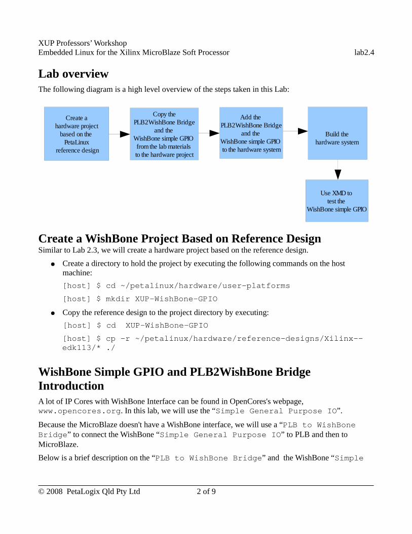
XUP Professors’ WorkshopEmbedded Linux for the Xilinx MicroBlaze Soft Processor lab2.4
Lab overviewThe following diagram is a high level overview of the steps taken in this Lab:
Create a WishBone Project Based on Reference DesignSimilar to Lab 2.3, we will create a hardware project based on the reference design.
● Create a directory to hold the project by executing the following commands on the host machine:
[host] $ cd ~/petalinux/hardware/user-platforms
[host] $ mkdir XUP-WishBone-GPIO
● Copy the reference design to the project directory by executing:
[host] $ cd XUP-WishBone-GPIO
[host] $ cp -r ~/petalinux/hardware/reference-designs/Xilinx--edk113/* ./
WishBone Simple GPIO and PLB2WishBone Bridge IntroductionA lot of IP Cores with WishBone Interface can be found in OpenCores's webpage, www.opencores.org. In this lab, we will use the “Simple General Purpose IO”.
Because the MicroBlaze doesn't have a WishBone interface, we will use a “PLB to WishBone Bridge” to connect the WishBone “Simple General Purpose IO” to PLB and then to MicroBlaze.
Below is a brief description on the “PLB to WishBone Bridge” and the WishBone “Simple
© 2008 PetaLogix Qld Pty Ltd 2 of 9
Copy thePLB2WishBone Bridge
and the WishBone simple GPIO from the lab materials to the hardware project
Use XMD to test the
WishBone simple GPIO
Add the PLB2WishBone Bridge
and the WishBone simple GPIO to the hardware system
Build the hardware system
Create ahardware project
based on the PetaLinux
reference design
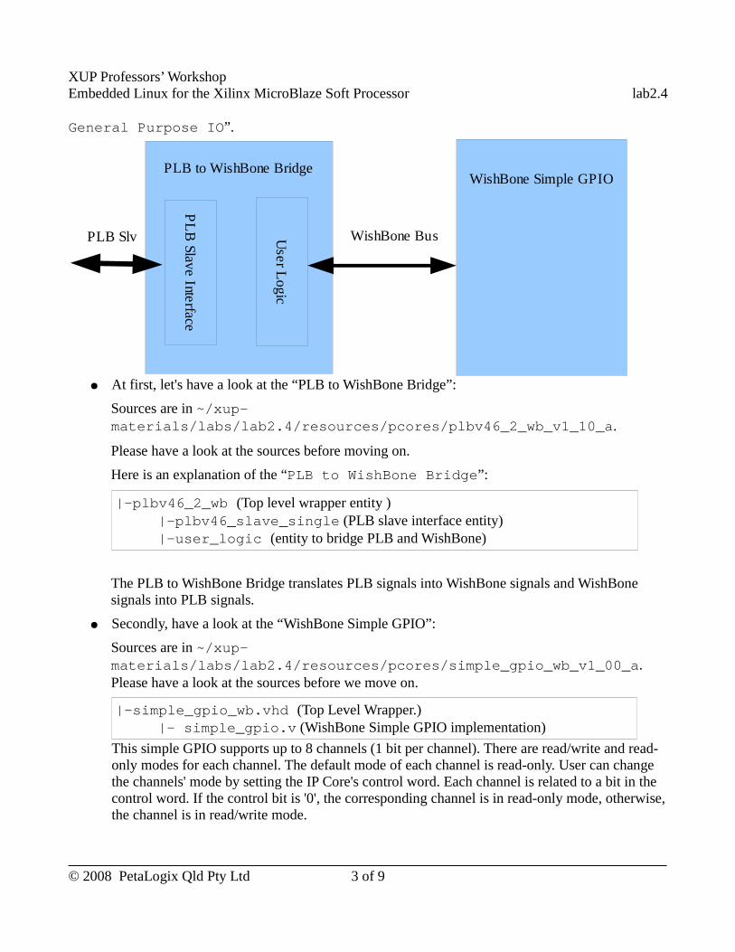
XUP Professors’ WorkshopEmbedded Linux for the Xilinx MicroBlaze Soft Processor lab2.4
General Purpose IO”.
● At first, let's have a look at the “PLB to WishBone Bridge”:
Sources are in ~/xup-materials/labs/lab2.4/resources/pcores/plbv46_2_wb_v1_10_a.
Please have a look at the sources before moving on.
Here is an explanation of the “PLB to WishBone Bridge”:
|-plbv46_2_wb (Top level wrapper entity )|-plbv46_slave_single (PLB slave interface entity)|-user_logic (entity to bridge PLB and WishBone)
The PLB to WishBone Bridge translates PLB signals into WishBone signals and WishBone signals into PLB signals.
● Secondly, have a look at the “WishBone Simple GPIO”:
Sources are in ~/xup-materials/labs/lab2.4/resources/pcores/simple_gpio_wb_v1_00_a. Please have a look at the sources before we move on.
|-simple_gpio_wb.vhd (Top Level Wrapper.)|- simple_gpio.v (WishBone Simple GPIO implementation)
This simple GPIO supports up to 8 channels (1 bit per channel). There are read/write and read-only modes for each channel. The default mode of each channel is read-only. User can change the channels' mode by setting the IP Core's control word. Each channel is related to a bit in the control word. If the control bit is '0', the corresponding channel is in read-only mode, otherwise, the channel is in read/write mode.
© 2008 PetaLogix Qld Pty Ltd 3 of 9
PLB to WishBone Bridge
PL
B Slave Interface
User L
ogic
PLB Slv
WishBone Simple GPIO
WishBone Bus
XUP Professors’ WorkshopEmbedded Linux for the Xilinx MicroBlaze Soft Processor lab2.4
Add WishBone IP Core to the ProjectAfter a brief introduction of the WishBone IP Core used in this lab, let's add them into the project we have just created.
● Copy the WishBone IP Cores from lab materials into our project's IP Cores repository by executing:
[host] $ cd ~/petalinux/hardware/user-platforms/XUP-WishBone-GPIO
[host] $ cp -r ~/xup-materials/labs/lab2.4/resources/pcores/* pcores/
● Add WishBone IP Cores into our project
○ Open the XUP-WishBone-GPIO project by executing the following command in the project directory:
[host] $ xps system.xmp
At this point, Version Management wizard might appear if the Xilinx version you used is newer than the one used to generate the reference design. If it is the case, click “Next” as required, and then “Finish” to upgrade the project files.
After the project is opened, the WishBone simple GPIO and the PLB to WishBone Bridge can be found in the IP catalog:
■ The “PLB to WishBone Bridge” is in “Project Local pcores”--> “Bus and Bridge”;
■ The “WishBone Simple GPIO” is in “Project Local pcores”--> “General Purpose IO”.
○ Add the WishBone IP Cores to the project:
Double click the “PLBv46 to Wishbone B3 Bridge” and “Simple GPIO with WishBone Interface” in the “IP Catalog” tab to add the IP Cores to the project.
You should be able to see the newly added IP Cores in the “System Assembly View”.
Connect the WishBone IP Cores to the SystemSo far, we have added the “WishBone Simple GPIO” and “PLB to WishBone Bridge” to the project. Now, we need to connect them to the system.
● Connect the “PLB to WishBone Bridge” to the PLB bus:
© 2008 PetaLogix Qld Pty Ltd 4 of 9
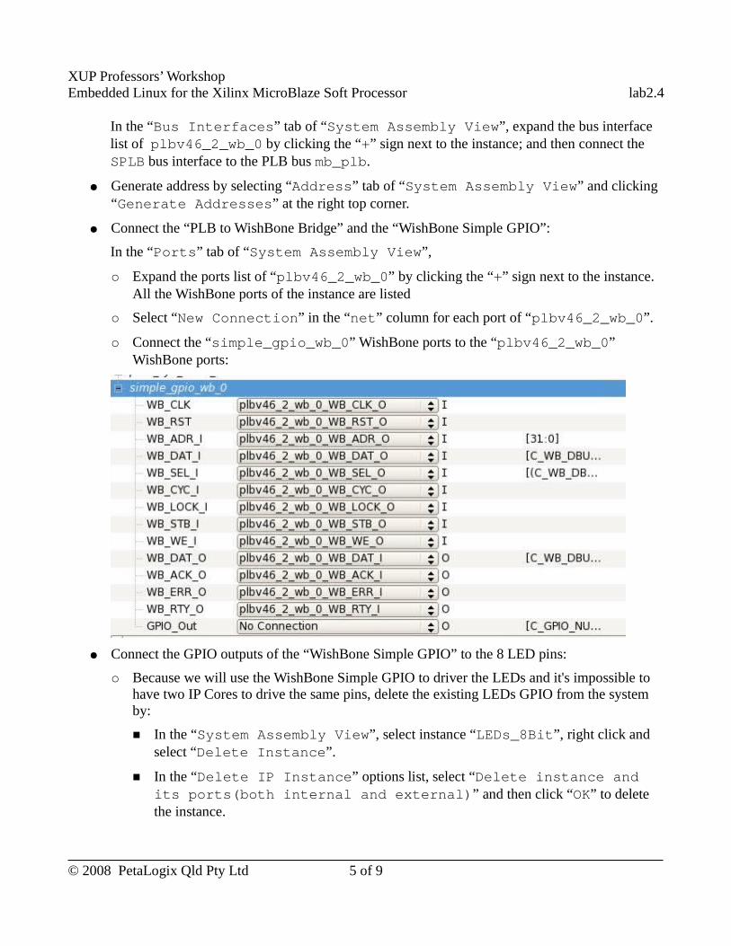
XUP Professors’ WorkshopEmbedded Linux for the Xilinx MicroBlaze Soft Processor lab2.4
In the “Bus Interfaces” tab of “System Assembly View”, expand the bus interface list of plbv46_2_wb_0 by clicking the “+” sign next to the instance; and then connect the SPLB bus interface to the PLB bus mb_plb.
● Generate address by selecting “Address” tab of “System Assembly View” and clicking “Generate Addresses” at the right top corner.
● Connect the “PLB to WishBone Bridge” and the “WishBone Simple GPIO”:
In the “Ports” tab of “System Assembly View”,
○ Expand the ports list of “plbv46_2_wb_0” by clicking the “+” sign next to the instance. All the WishBone ports of the instance are listed
○ Select “New Connection” in the “net” column for each port of “plbv46_2_wb_0”.
○ Connect the “simple_gpio_wb_0” WishBone ports to the “plbv46_2_wb_0” WishBone ports:
● Connect the GPIO outputs of the “WishBone Simple GPIO” to the 8 LED pins:
○ Because we will use the WishBone Simple GPIO to driver the LEDs and it's impossible to have two IP Cores to drive the same pins, delete the existing LEDs GPIO from the system by:
■ In the “System Assembly View”, select instance “LEDs_8Bit”, right click and select “Delete Instance”.
■ In the “Delete IP Instance” options list, select “Delete instance and its ports(both internal and external)” and then click “OK” to delete the instance.
© 2008 PetaLogix Qld Pty Ltd 5 of 9
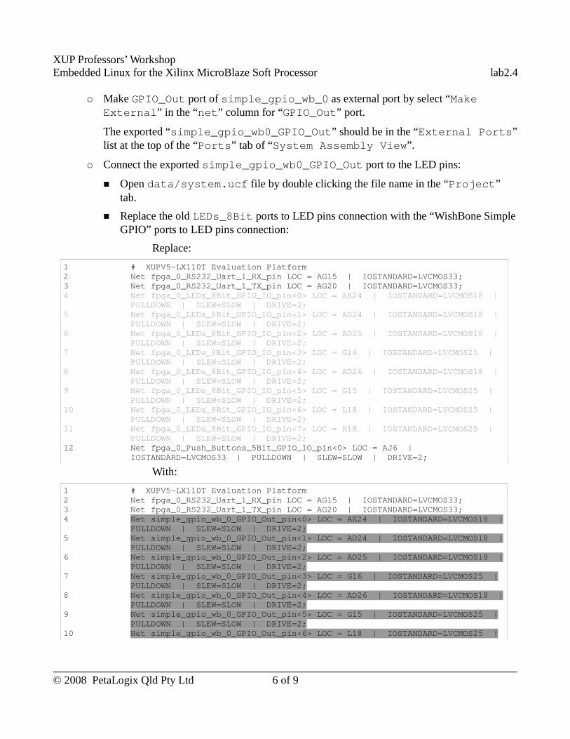
XUP Professors’ WorkshopEmbedded Linux for the Xilinx MicroBlaze Soft Processor lab2.4
○ Make GPIO_Out port of simple_gpio_wb_0 as external port by select “Make External” in the “net” column for “GPIO_Out” port.
The exported “simple_gpio_wb0_GPIO_Out” should be in the “External Ports” list at the top of the “Ports” tab of “System Assembly View”.
○ Connect the exported simple_gpio_wb0_GPIO_Out port to the LED pins:
■ Open data/system.ucf file by double clicking the file name in the “Project” tab.
■ Replace the old LEDs_8Bit ports to LED pins connection with the “WishBone Simple GPIO” ports to LED pins connection:
Replace:
1 # XUPV5-LX110T Evaluation Platform2 Net fpga_0_RS232_Uart_1_RX_pin LOC = AG15 | IOSTANDARD=LVCMOS33;3 Net fpga_0_RS232_Uart_1_TX_pin LOC = AG20 | IOSTANDARD=LVCMOS33;4 Net fpga_0_LEDs_8Bit_GPIO_IO_pin<0> LOC = AE24 | IOSTANDARD=LVCMOS18 |
PULLDOWN | SLEW=SLOW | DRIVE=2;5 Net fpga_0_LEDs_8Bit_GPIO_IO_pin<1> LOC = AD24 | IOSTANDARD=LVCMOS18 |
PULLDOWN | SLEW=SLOW | DRIVE=2;6 Net fpga_0_LEDs_8Bit_GPIO_IO_pin<2> LOC = AD25 | IOSTANDARD=LVCMOS18 |
PULLDOWN | SLEW=SLOW | DRIVE=2;7 Net fpga_0_LEDs_8Bit_GPIO_IO_pin<3> LOC = G16 | IOSTANDARD=LVCMOS25 |
PULLDOWN | SLEW=SLOW | DRIVE=2;8 Net fpga_0_LEDs_8Bit_GPIO_IO_pin<4> LOC = AD26 | IOSTANDARD=LVCMOS18 |
PULLDOWN | SLEW=SLOW | DRIVE=2;9 Net fpga_0_LEDs_8Bit_GPIO_IO_pin<5> LOC = G15 | IOSTANDARD=LVCMOS25 |
PULLDOWN | SLEW=SLOW | DRIVE=2;10 Net fpga_0_LEDs_8Bit_GPIO_IO_pin<6> LOC = L18 | IOSTANDARD=LVCMOS25 |
PULLDOWN | SLEW=SLOW | DRIVE=2;11 Net fpga_0_LEDs_8Bit_GPIO_IO_pin<7> LOC = H18 | IOSTANDARD=LVCMOS25 |
PULLDOWN | SLEW=SLOW | DRIVE=2;12 Net fpga_0_Push_Buttons_5Bit_GPIO_IO_pin<0> LOC = AJ6 |
IOSTANDARD=LVCMOS33 | PULLDOWN | SLEW=SLOW | DRIVE=2;
With:
1 # XUPV5-LX110T Evaluation Platform2 Net fpga_0_RS232_Uart_1_RX_pin LOC = AG15 | IOSTANDARD=LVCMOS33;3 Net fpga_0_RS232_Uart_1_TX_pin LOC = AG20 | IOSTANDARD=LVCMOS33;4 Net simple_gpio_wb_0_GPIO_Out_pin<0> LOC = AE24 | IOSTANDARD=LVCMOS18 |
PULLDOWN | SLEW=SLOW | DRIVE=2;5 Net simple_gpio_wb_0_GPIO_Out_pin<1> LOC = AD24 | IOSTANDARD=LVCMOS18 |
PULLDOWN | SLEW=SLOW | DRIVE=2;6 Net simple_gpio_wb_0_GPIO_Out_pin<2> LOC = AD25 | IOSTANDARD=LVCMOS18 |
PULLDOWN | SLEW=SLOW | DRIVE=2;7 Net simple_gpio_wb_0_GPIO_Out_pin<3> LOC = G16 | IOSTANDARD=LVCMOS25 |
PULLDOWN | SLEW=SLOW | DRIVE=2;8 Net simple_gpio_wb_0_GPIO_Out_pin<4> LOC = AD26 | IOSTANDARD=LVCMOS18 |
PULLDOWN | SLEW=SLOW | DRIVE=2;9 Net simple_gpio_wb_0_GPIO_Out_pin<5> LOC = G15 | IOSTANDARD=LVCMOS25 |
PULLDOWN | SLEW=SLOW | DRIVE=2;10 Net simple_gpio_wb_0_GPIO_Out_pin<6> LOC = L18 | IOSTANDARD=LVCMOS25 |
© 2008 PetaLogix Qld Pty Ltd 6 of 9
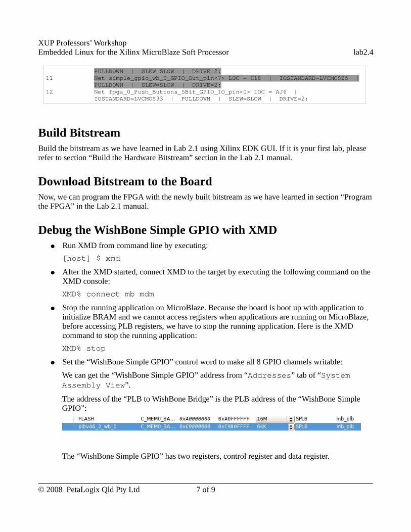
XUP Professors’ WorkshopEmbedded Linux for the Xilinx MicroBlaze Soft Processor lab2.4
PULLDOWN | SLEW=SLOW | DRIVE=2;11 Net simple_gpio_wb_0_GPIO_Out_pin<7> LOC = H18 | IOSTANDARD=LVCMOS25 |
PULLDOWN | SLEW=SLOW | DRIVE=2;12 Net fpga_0_Push_Buttons_5Bit_GPIO_IO_pin<0> LOC = AJ6 |
IOSTANDARD=LVCMOS33 | PULLDOWN | SLEW=SLOW | DRIVE=2;
Build BitstreamBuild the bitstream as we have learned in Lab 2.1 using Xilinx EDK GUI. If it is your first lab, please refer to section “Build the Hardware Bitstream” section in the Lab 2.1 manual.
Download Bitstream to the BoardNow, we can program the FPGA with the newly built bitstream as we have learned in section “Program the FPGA” in the Lab 2.1 manual.
Debug the WishBone Simple GPIO with XMD● Run XMD from command line by executing:
[host] $ xmd
● After the XMD started, connect XMD to the target by executing the following command on the XMD console:
XMD% connect mb mdm
● Stop the running application on MicroBlaze. Because the board is boot up with application to initialize BRAM and we cannot access registers when applications are running on MicroBlaze, before accessing PLB registers, we have to stop the running application. Here is the XMD command to stop the running application:
XMD% stop
● Set the “WishBone Simple GPIO” control word to make all 8 GPIO channels writable:
We can get the “WishBone Simple GPIO” address from “Addresses” tab of “System Assembly View”.
The address of the “PLB to WishBone Bridge” is the PLB address of the “WishBone Simple GPIO”:
The “WishBone Simple GPIO” has two registers, control register and data register.
© 2008 PetaLogix Qld Pty Ltd 7 of 9
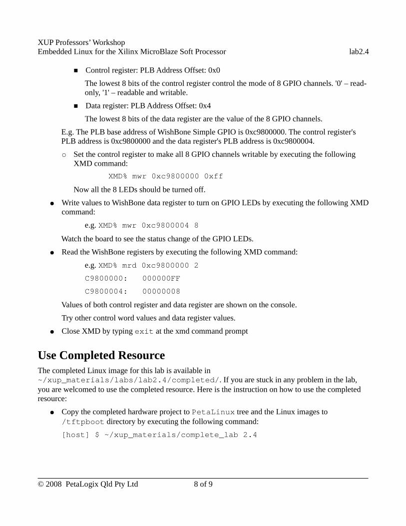
XUP Professors’ WorkshopEmbedded Linux for the Xilinx MicroBlaze Soft Processor lab2.4
■ Control register: PLB Address Offset: 0x0
The lowest 8 bits of the control register control the mode of 8 GPIO channels. '0' – read-only, '1' – readable and writable.
■ Data register: PLB Address Offset: 0x4
The lowest 8 bits of the data register are the value of the 8 GPIO channels.
E.g. The PLB base address of WishBone Simple GPIO is 0xc9800000. The control register's PLB address is 0xc9800000 and the data register's PLB address is 0xc9800004.
○ Set the control register to make all 8 GPIO channels writable by executing the following XMD command:
XMD% mwr 0xc9800000 0xff
Now all the 8 LEDs should be turned off.
● Write values to WishBone data register to turn on GPIO LEDs by executing the following XMD command:
e.g. XMD% mwr 0xc9800004 8
Watch the board to see the status change of the GPIO LEDs.
● Read the WishBone registers by executing the following XMD command:
e.g. XMD% mrd 0xc9800000 2
C9800000: 000000FF
C9800004: 00000008
Values of both control register and data register are shown on the console.
Try other control word values and data register values.
● Close XMD by typing exit at the xmd command prompt
Use Completed ResourceThe completed Linux image for this lab is available in ~/xup_materials/labs/lab2.4/completed/. If you are stuck in any problem in the lab, you are welcomed to use the completed resource. Here is the instruction on how to use the completed resource:
● Copy the completed hardware project to PetaLinux tree and the Linux images to /tftpboot directory by executing the following command:
[host] $ ~/xup_materials/complete_lab 2.4
© 2008 PetaLogix Qld Pty Ltd 8 of 9
XUP Professors’ WorkshopEmbedded Linux for the Xilinx MicroBlaze Soft Processor lab2.4
● Download the bitstream to the board by executing:
[host] $ cd ~/petalinux/hardware/user-platforms/XUP-WishBone-GPIO
[host] $ impact -batch etc/download.cmd
This command will download the bitstream implementation/download.bit to the board. (iMPACT is an Xilinx device configuration tool.)
OutcomesAt the completion of this lab you should understand
● what is WishBone bus ● how to connect a WishBone IP Core to MicroBlaze.● where to find IP cores on the OpenCores website.
Document VersionDoc ID: lab2_4Build: xupv5-edk113-7425Date: 2010-01-21
© 2008 PetaLogix Qld Pty Ltd 9 of 9
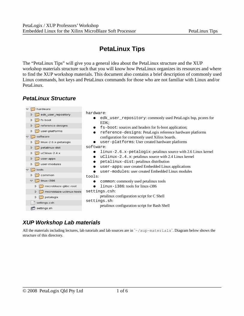
PetaLogix / XUP Professors’ WorkshopEmbedded Linux for the Xilinx MicroBlaze Soft Processor PetaLinux Tips
PetaLinux Tips
The “PetaLinux Tips” will give you a general idea about the PetaLinux structure and the XUP workshop materials structure such that you will know how PetaLinux organizes its resources and where to find the XUP workshop materials. This document also contains a brief description of commonly used Linux commands, hot keys and PetaLinux commands for those who are not familiar with Linux and/or PetaLinux.
PetaLinux Structure
hardware:● edk_user_repository: commonly used PetaLogix bsp, pcores for
EDK;● fs-boot: sources and headers for fs-boot application;● reference-designs: PetaLogix reference hardware platforms
configuration for commonly used Xilinx boards.● user-platforms: User created hardware platforms
software:● linux-2.6.x-petalogix: petalinux source with 2.6 Linux kernel● uClinux-2.4.x: petalinux source with 2.4 Linux kernel● petalinux-dist: petalinux distribution● user-apps: user created Embedded Linux applications● user-modules: user created Embedded Linux modules
tools:● common: commonly used petalinux tools● linux-i386: tools for linux-i386
settings.csh: petalinux configuration script for C Shell
settings.sh:petalinux configuration script for Bash Shell
XUP Workshop Lab materialsAll the materials including lectures, lab tutorials and lab sources are in `~/xup-materials`. Diagram below shows the structure of this directory.
© 2008 PetaLogix Qld Pty Ltd 1 of 6
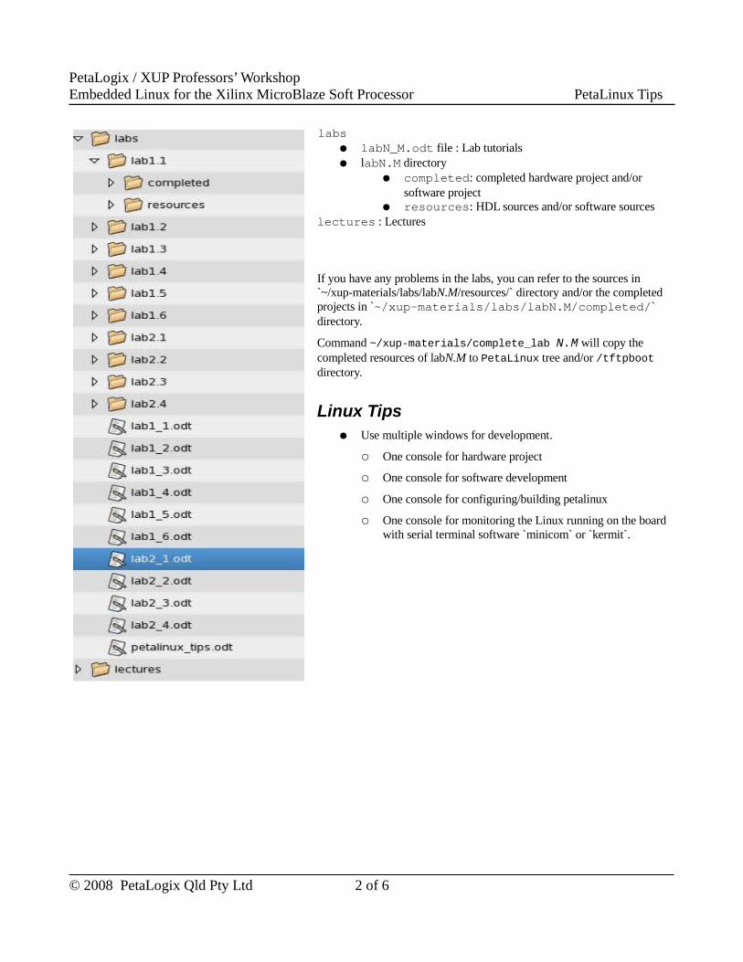
PetaLogix / XUP Professors’ WorkshopEmbedded Linux for the Xilinx MicroBlaze Soft Processor PetaLinux Tips
● labs● labN_M.odt file : Lab tutorials● labN.M directory
● completed: completed hardware project and/or software project
● resources: HDL sources and/or software sourceslectures : Lectures
If you have any problems in the labs, you can refer to the sources in `~/xup-materials/labs/labN.M/resources/` directory and/or the completed projects in `~/xup-materials/labs/labN.M/completed/` directory.
Command ~/xup-materials/complete_lab N.M will copy the completed resources of labN.M to PetaLinux tree and/or /tftpboot directory.
Linux Tips● Use multiple windows for development.
○ One console for hardware project
○ One console for software development
○ One console for configuring/building petalinux
○ One console for monitoring the Linux running on the board with serial terminal software `minicom` or `kermit`.
© 2008 PetaLogix Qld Pty Ltd 2 of 6
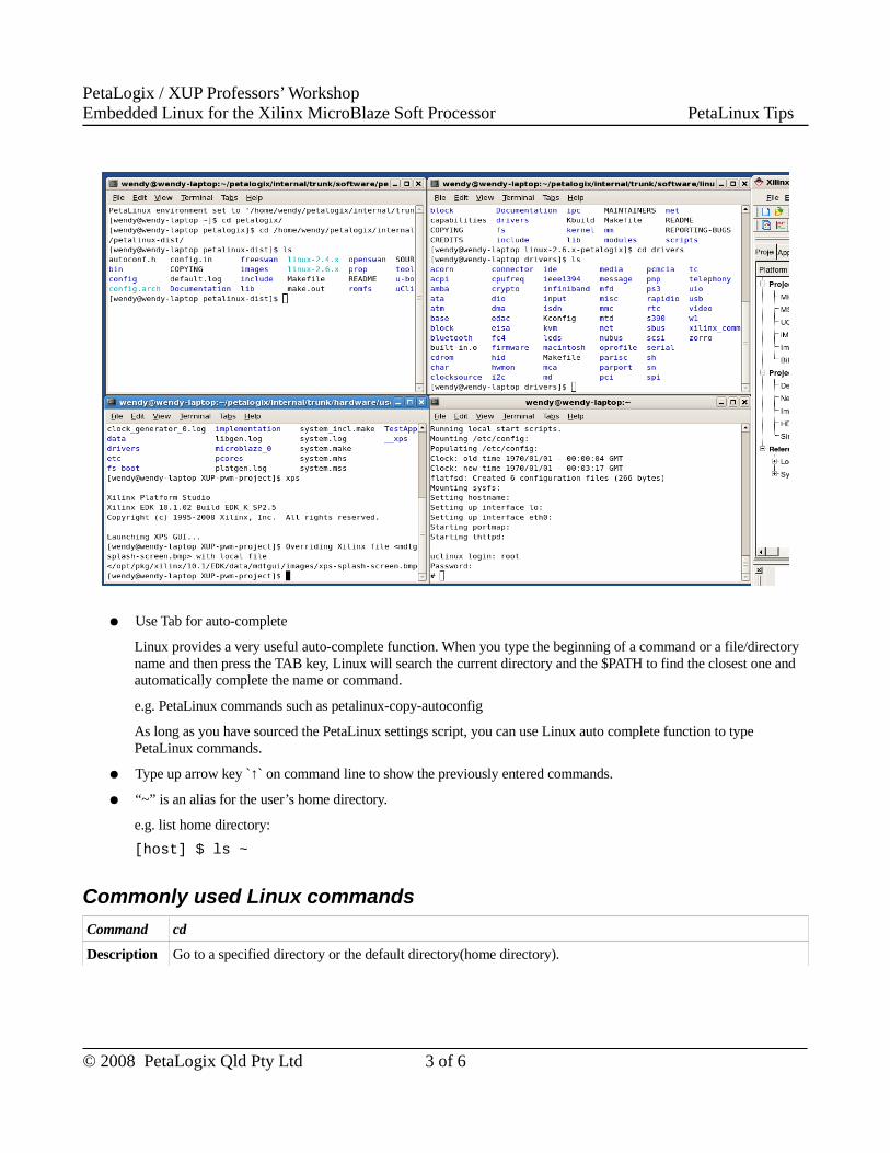
PetaLogix / XUP Professors’ WorkshopEmbedded Linux for the Xilinx MicroBlaze Soft Processor PetaLinux Tips
● Use Tab for auto-complete
Linux provides a very useful auto-complete function. When you type the beginning of a command or a file/directory name and then press the TAB key, Linux will search the current directory and the $PATH to find the closest one and automatically complete the name or command.
e.g. PetaLinux commands such as petalinux-copy-autoconfig
As long as you have sourced the PetaLinux settings script, you can use Linux auto complete function to type PetaLinux commands.
● Type up arrow key `↑` on command line to show the previously entered commands.
● “~” is an alias for the user’s home directory.
e.g. list home directory:
[host] $ ls ~
Commonly used Linux commands
Command cd
Description Go to a specified directory or the default directory(home directory).
© 2008 PetaLogix Qld Pty Ltd 3 of 6
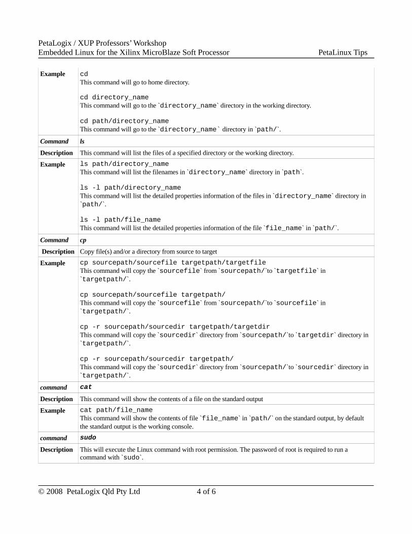
PetaLogix / XUP Professors’ WorkshopEmbedded Linux for the Xilinx MicroBlaze Soft Processor PetaLinux Tips
Example cd This command will go to home directory.
cd directory_nameThis command will go to the `directory_name` directory in the working directory.
cd path/directory_nameThis command will go to the `directory_name` directory in `path/`.
Command ls
Description This command will list the files of a specified directory or the working directory.
Example ls path/directory_nameThis command will list the filenames in `directory_name` directory in `path`.
ls -l path/directory_nameThis command will list the detailed properties information of the files in `directory_name` directory in `path/`.
ls -l path/file_nameThis command will list the detailed properties information of the file `file_name` in `path/`.
Command cp
Description Copy file(s) and/or a directory from source to target
Example cp sourcepath/sourcefile targetpath/targetfileThis command will copy the `sourcefile` from `sourcepath/`to `targetfile` in `targetpath/`.
cp sourcepath/sourcefile targetpath/This command will copy the `sourcefile` from `sourcepath/`to `sourcefile` in `targetpath/`.
cp -r sourcepath/sourcedir targetpath/targetdirThis command will copy the `sourcedir` directory from `sourcepath/`to `targetdir` directory in `targetpath/`.
cp -r sourcepath/sourcedir targetpath/This command will copy the `sourcedir` directory from `sourcepath/`to `sourcedir` directory in `targetpath/`.
command cat
Description This command will show the contents of a file on the standard output
Example cat path/file_nameThis command will show the contents of file `file_name` in `path/` on the standard output, by default the standard output is the working console.
command sudo
Description This will execute the Linux command with root permission. The password of root is required to run a command with `sudo`.
© 2008 PetaLogix Qld Pty Ltd 4 of 6
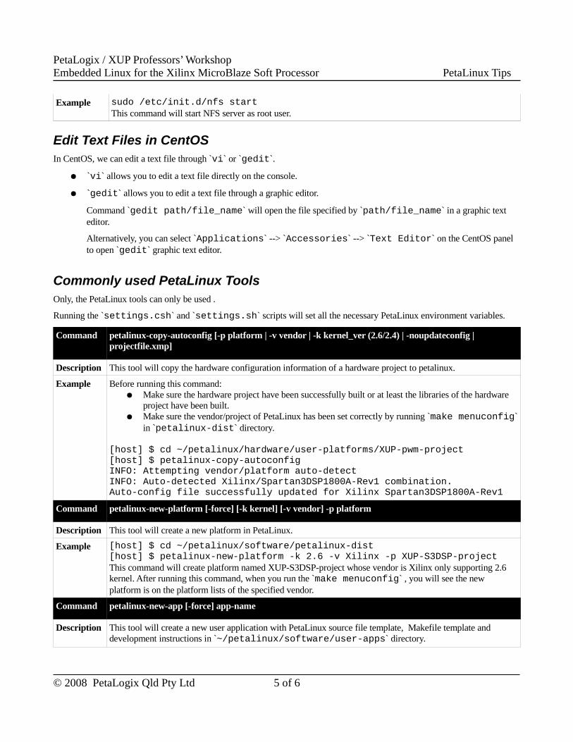
PetaLogix / XUP Professors’ WorkshopEmbedded Linux for the Xilinx MicroBlaze Soft Processor PetaLinux Tips
Example sudo /etc/init.d/nfs startThis command will start NFS server as root user.
Edit Text Files in CentOSIn CentOS, we can edit a text file through `vi` or `gedit`.
● `vi` allows you to edit a text file directly on the console.
● `gedit` allows you to edit a text file through a graphic editor.
Command `gedit path/file_name` will open the file specified by `path/file_name` in a graphic text editor.
Alternatively, you can select `Applications` --> `Accessories` --> `Text Editor` on the CentOS panel to open `gedit` graphic text editor.
Commonly used PetaLinux ToolsOnly, the PetaLinux tools can only be used .
Running the `settings.csh` and `settings.sh` scripts will set all the necessary PetaLinux environment variables.
Command petalinux-copy-autoconfig [-p platform | -v vendor | -k kernel_ver (2.6/2.4) | -noupdateconfig | projectfile.xmp]
Description This tool will copy the hardware configuration information of a hardware project to petalinux.
Example Before running this command:● Make sure the hardware project have been successfully built or at least the libraries of the hardware
project have been built.● Make sure the vendor/project of PetaLinux has been set correctly by running `make menuconfig`
in `petalinux-dist` directory.
[host] $ cd ~/petalinux/hardware/user-platforms/XUP-pwm-project[host] $ petalinux-copy-autoconfigINFO: Attempting vendor/platform auto-detect INFO: Auto-detected Xilinx/Spartan3DSP1800A-Rev1 combination. Auto-config file successfully updated for Xilinx Spartan3DSP1800A-Rev1
Command petalinux-new-platform [-force] [-k kernel] [-v vendor] -p platform
Description This tool will create a new platform in PetaLinux.
Example [host] $ cd ~/petalinux/software/petalinux-dist[host] $ petalinux-new-platform -k 2.6 -v Xilinx -p XUP-S3DSP-projectThis command will create platform named XUP-S3DSP-project whose vendor is Xilinx only supporting 2.6 kernel. After running this command, when you run the `make menuconfig` , you will see the new platform is on the platform lists of the specified vendor.
Command petalinux-new-app [-force] app-name
Description This tool will create a new user application with PetaLinux source file template, Makefile template and development instructions in `~/petalinux/software/user-apps` directory.
© 2008 PetaLogix Qld Pty Ltd 5 of 6
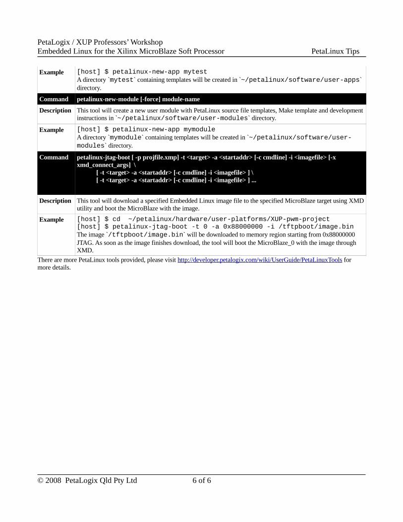
PetaLogix / XUP Professors’ WorkshopEmbedded Linux for the Xilinx MicroBlaze Soft Processor PetaLinux Tips
Example [host] $ petalinux-new-app mytestA directory `mytest` containing templates will be created in `~/petalinux/software/user-apps` directory.
Command petalinux-new-module [-force] module-name
Description This tool will create a new user module with PetaLinux source file templates, Make template and development instructions in `~/petalinux/software/user-modules` directory.
Example [host] $ petalinux-new-app mymoduleA directory `mymodule` containing templates will be created in `~/petalinux/software/user-modules` directory.
Command petalinux-jtag-boot [ -p projfile.xmp] -t <target> -a <startaddr> [-c cmdline] -i <imagefile> [-x xmd_connect_args] \ [ -t <target> -a <startaddr> [-c cmdline] -i <imagefile> ] \ [ -t <target> -a <startaddr> [-c cmdline] -i <imagefile> ] ...
Description This tool will download a specified Embedded Linux image file to the specified MicroBlaze target using XMD utility and boot the MicroBlaze with the image.
Example [host] $ cd ~/petalinux/hardware/user-platforms/XUP-pwm-project[host] $ petalinux-jtag-boot -t 0 -a 0x88000000 -i /tftpboot/image.binThe image `/tftpboot/image.bin` will be downloaded to memory region starting from 0x88000000 JTAG. As soon as the image finishes download, the tool will boot the MicroBlaze_0 with the image through XMD.
There are more PetaLinux tools provided, please visit http://developer.petalogix.com/wiki/UserGuide/PetaLinuxTools for more details.
© 2008 PetaLogix Qld Pty Ltd 6 of 6