Embed Size (px)
Citation preview

Embedded Systems
May 2016
Cristian Rotariu
Dept. of of Biomedical Sciences
“Grigore T Popa” University of Medicine and Pharmacy of Iasi,
Romania
Introduction
An embedded system is a dedicated computer systemdesigned for one or two specific functions.
This system is embedded as a part of a complete devicesystem that may include hardware, such as electrical andmechanical components.
Because an embedded system is engineered to performcertain tasks only, design engineers may optimize size,cost, power consumption, reliability and performance.
Introduction
Embedded systems are managed by single or multipleprocessing cores in the form of:
microcontrollers
digital signal processors (DSP)
field-programmable gate arrays (FPGA),
application-specific integrated circuits (ASIC)
gate arrays.
These processing components are integrated withcomponents dedicated to handling electric and/ormechanical interfacing.
Examples of Embedded Systems
1. Embedded System for remote monitoringof atrial fibrillation
2. Embedded System for remote monitoringof SpO2 and HR
ES for Remote Monitoring of AF
Atrial fibrillation (AF) is the most common chronic cardiacarrhythmia;
AF affects about 0.4% to 1.0% of the entire population;
AF increases the mortality rate;
The irregularity of the heart beat intervals can be used forthe detection of AF episodes.
ES for Remote Monitoring of AF
The homecare monitoring of patients represents analternative to medical supervision within hospitals;
Patient monitoring requires the use of sensors attached bywires to the medical devices, which limits the patient'sactivity;
ES is based on wireless devices for patient monitoring in alimited area.
ES for Remote Monitoring of AF
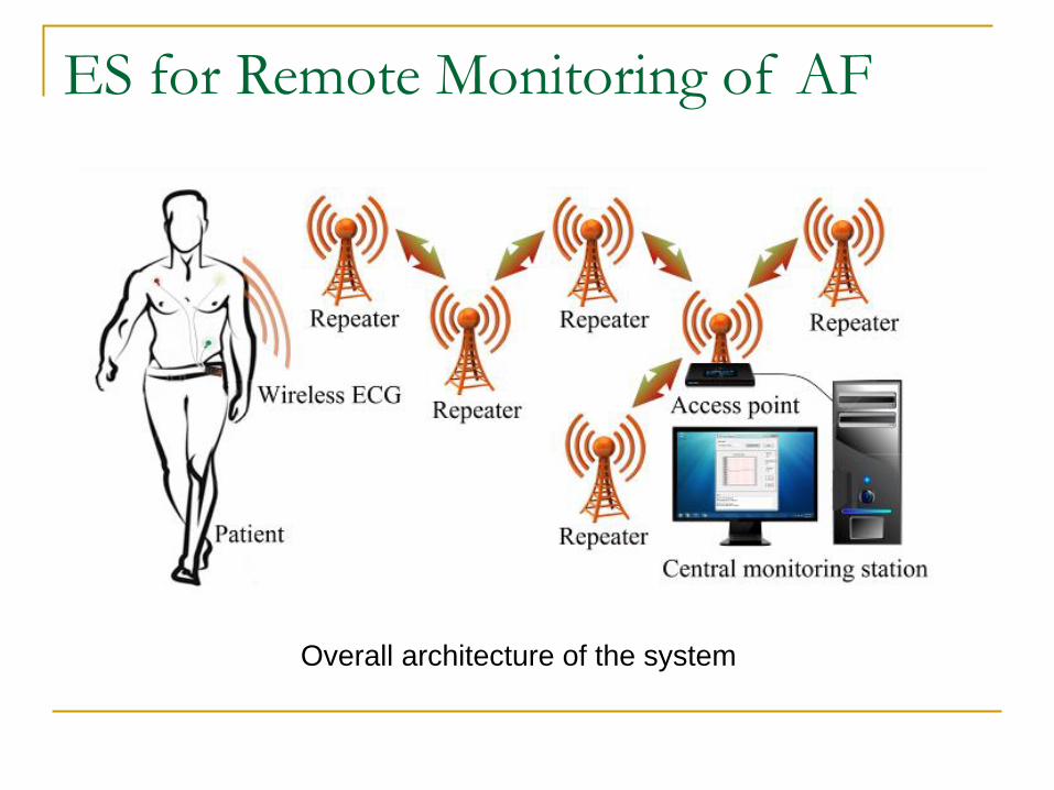
Overall architecture of the system
ES for Remote Monitoring of AF
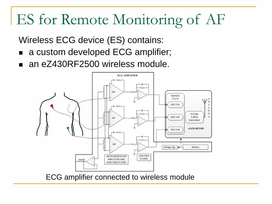
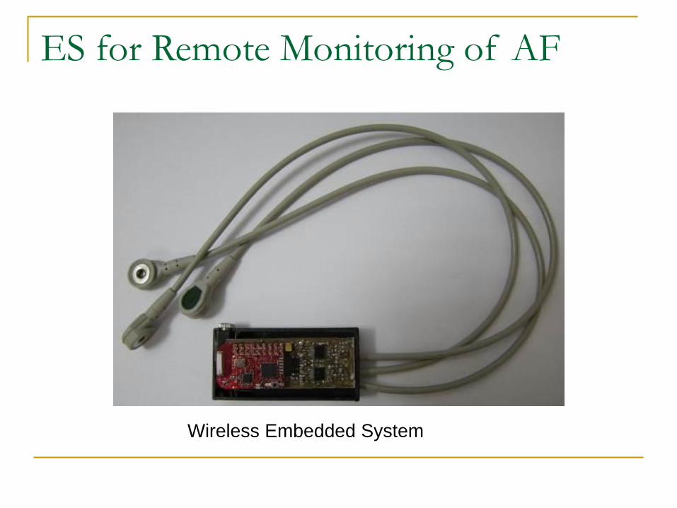
Wireless ECG device (ES) contains:
a custom developed ECG amplifier;
an eZ430RF2500 wireless module.
ECG amplifier connected to wireless module
ES for Remote Monitoring of AF
We used the SimpliciTi protocol to transfer data fromwireless ECG device to central monitoring station;
The ES was configured as ED, the wireless moduleconnected to central monitoring station as AP, and severalothers are configured as RE;
Data transmission rate between the ED and AP through REdepends on patient’s HR, and usually range from 0.5Hz (forHR = 30bpm) to 3Hz (for HR = 180bpm).
ES for Remote Monitoring of AF
Wireless Embedded System
ES for Remote Monitoring of AF
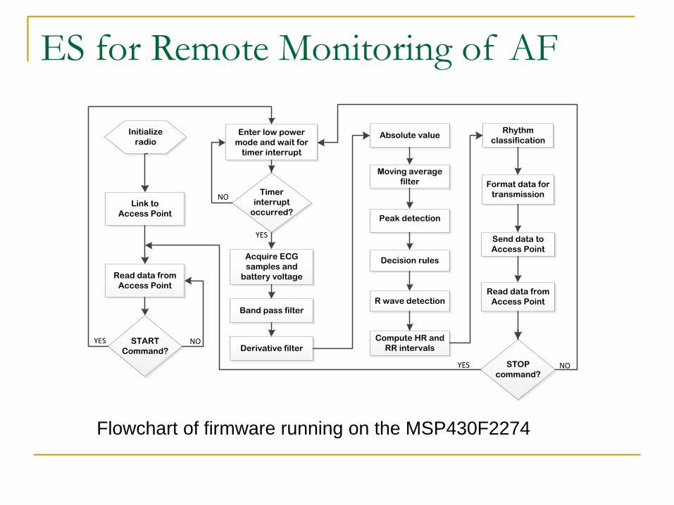
Flowchart of firmware running on the MSP430F2274
Link to
Access Point
Read data from
Access Point
Enter low power
mode and wait for
timer interrupt
Acquire ECG
samples and
battery voltage
Derivative filter
Format data for
transmission
Send data to
Access Point
Read data from
Access Point
START
Command?
Initialize
radio
STOP
command?
Timer
interrupt
occurred?
YES
NO
NOYES
NOYES
Absolute value
Moving average
filter
Peak detection
Decision rules
Compute HR and
RR intervals
Rhythm
classification
R wave detectionBand pass filter
ES for Remote Monitoring of AF
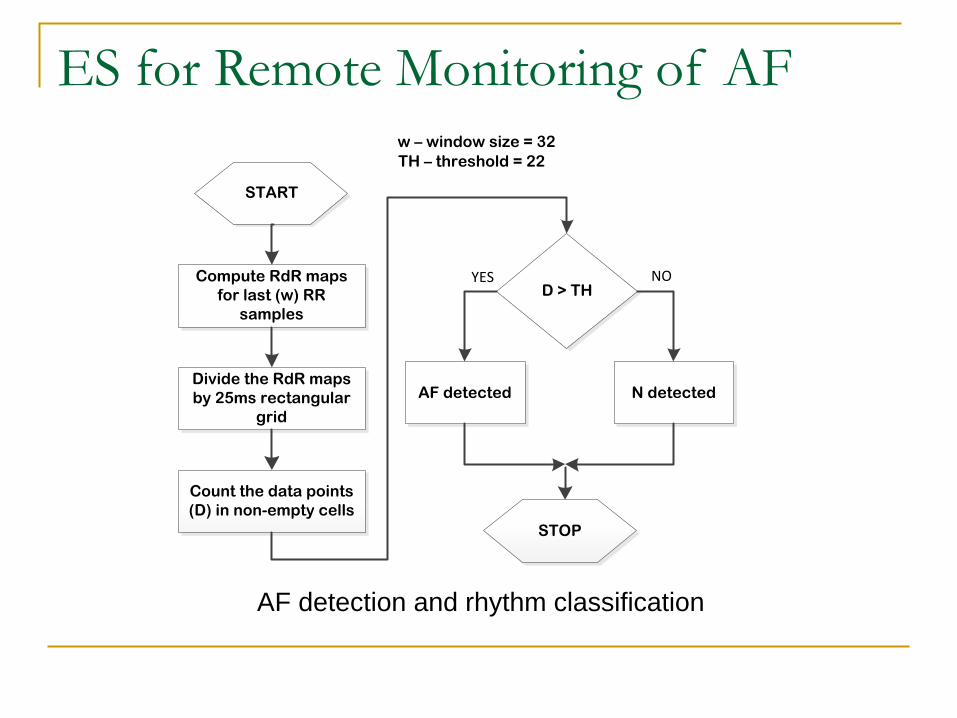
Compute RdR maps
for last (w) RR
samples
START
Divide the RdR maps
by 25ms rectangular
grid
Count the data points
(D) in non-empty cells
D > TH
AF detected N detected
YES NO
STOP
w – window size = 32
TH – threshold = 22
AF detection and rhythm classification
ES for Remote Monitoring of AF
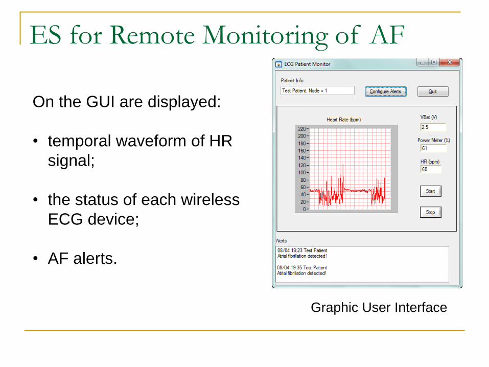
Graphic User Interface
On the GUI are displayed:
• temporal waveform of HR
signal;
• the status of each wireless
ECG device;
• AF alerts.
ES for Remote Monitoring of AF
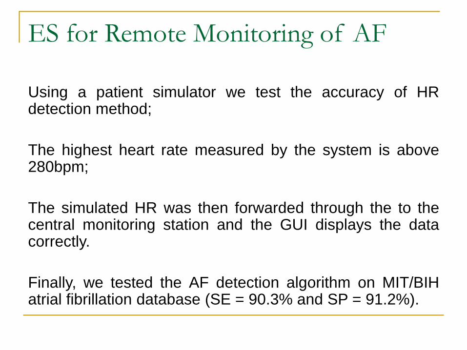
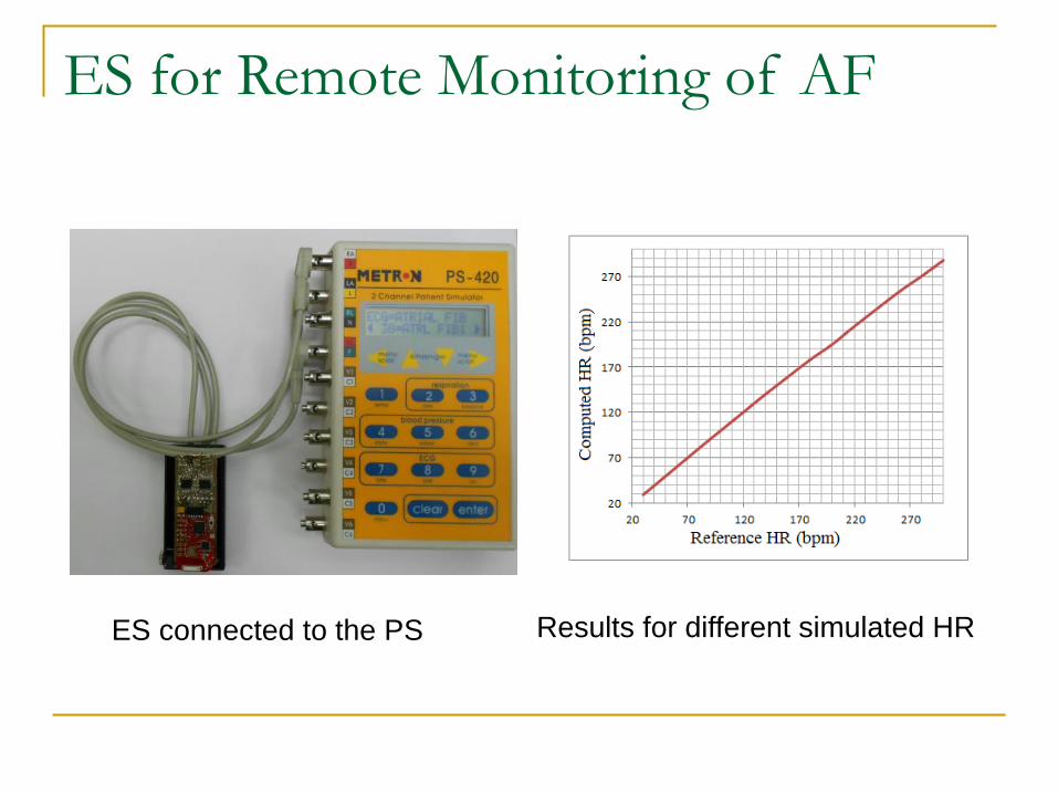
Using a patient simulator we test the accuracy of HRdetection method;
The highest heart rate measured by the system is above280bpm;
The simulated HR was then forwarded through the to thecentral monitoring station and the GUI displays the datacorrectly.
Finally, we tested the AF detection algorithm on MIT/BIHatrial fibrillation database (SE = 90.3% and SP = 91.2%).
ES for Remote Monitoring of AF
ES connected to the PS Results for different simulated HR
ES for Remote Monitoring of SpO2
and HR
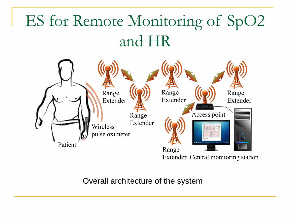
Reliable long term monitoring of patients is useful for anumber of medical conditions: heart diseases, sleep-related breathing disorder, patients with chronic diseases;
Oxygen saturation is an important vital parameter, used fordetection of hypoxemia;
Heart rate is physiological parameter commonly used bywireless patient monitoring systems.
ES for Remote Monitoring of SpO2
and HR
The advances of the IC technology, wireless networks, andmedical sensors have opened the way to miniature, lowpower, and intelligent monitoring pulse oximeters, suitablefor many wireless medical applications;
Monitoring patient’s SpO2 and HR within hospital or hishome requires the use of sensors attached by wires to themedical devices, which limits the patient's activity;
The SpO2 and HR are continuously measured usingcommercially available pulse oximeters and the results aretransmitted to a central monitoring station.
ES for Remote Monitoring of SpO2
and HR
Overall architecture of the system
ES for Remote Monitoring of SpO2
and HR
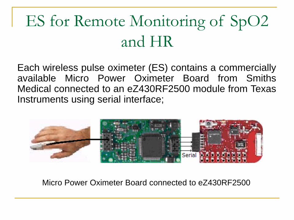
Each wireless pulse oximeter (ES) contains a commerciallyavailable Micro Power Oximeter Board from SmithsMedical connected to an eZ430RF2500 module from TexasInstruments using serial interface;
Micro Power Oximeter Board connected to eZ430RF2500
ES for Remote Monitoring of SpO2
and HR
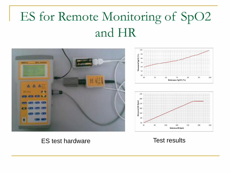
The pulse oximeter used to collect the SpO2 and HR hasthe following specifications:
measurement range of 0–99% SpO2 with ±2% accuracy for70–99% SpO2;
pulse rate measurement range of 30–254bpm with ±2bpmor ±2% accuracy.
ES for Remote Monitoring of SpO2
and HRWe used the SimpliciTi protocol from Texas Instruments totransfer data from wireless pulse oximeter to centralmonitoring station;
The ES was configured as End Device, the eZ430RF2500connected to central monitoring station as Access Point,and several others are configured as Range Extenders;
Data transmission rate between the ED and AP through REwas set at one transmission per second.
ES for Remote Monitoring of SpO2
and HR
Link to
Access Point
Read data from
Access Point
Enter low power
mode and wait for
serial interrupt
Acquire SpO2,
HR, and PPG
Acquire battery
voltage
Format data for
transmission
Send data to
Access Point
Read data from
Access Point
START
Command?
Initialize
radio
STOP
command?
Serial
interrupt
occurred?
YES
NO
NO YESNO YES
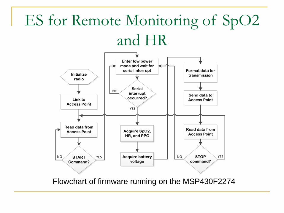
Flowchart of firmware running on the MSP430F2274
ES for Remote Monitoring of SpO2
and HR
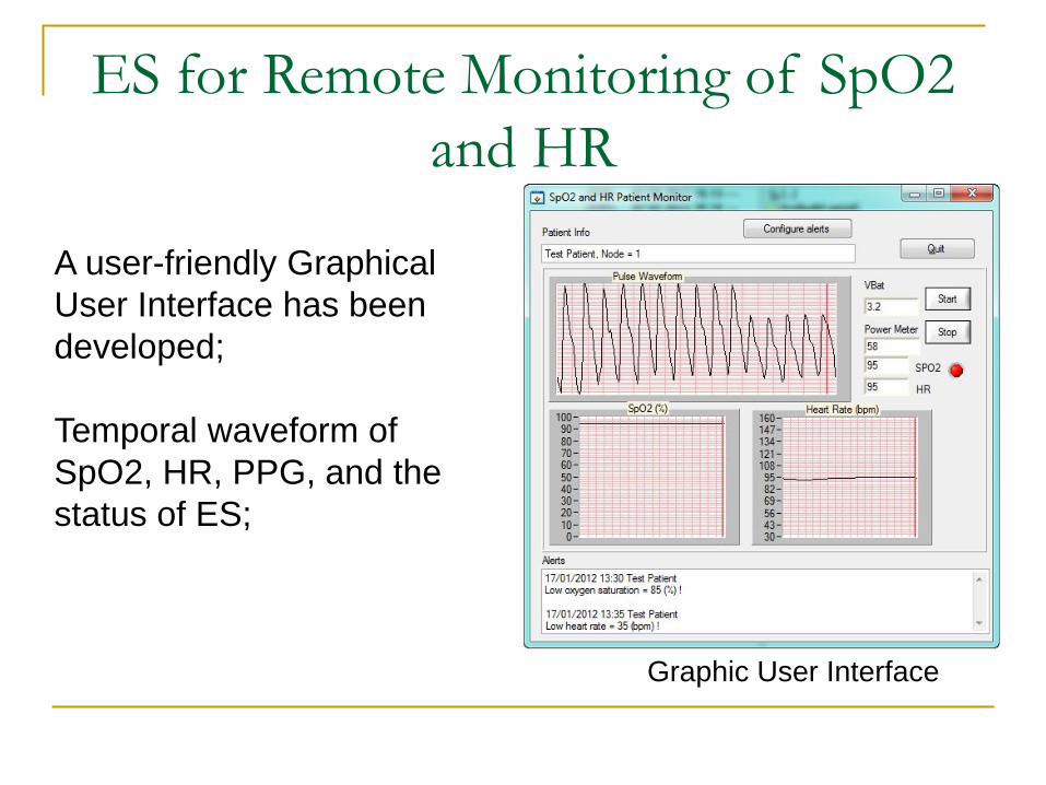
Graphic User Interface
A user-friendly Graphical
User Interface has been
developed;
Temporal waveform of
SpO2, HR, PPG, and the
status of ES;
ES for Remote Monitoring of SpO2
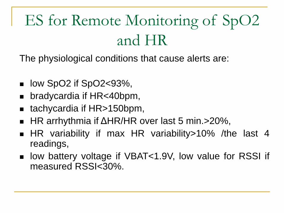
and HRThe physiological conditions that cause alerts are:
low SpO2 if SpO2<93%,
bradycardia if HR<40bpm,
tachycardia if HR>150bpm,
HR arrhythmia if ΔHR/HR over last 5 min.>20%,
HR variability if max HR variability>10% /the last 4readings,
low battery voltage if VBAT<1.9V, low value for RSSI ifmeasured RSSI<30%.
ES for Remote Monitoring of SpO2
and HR
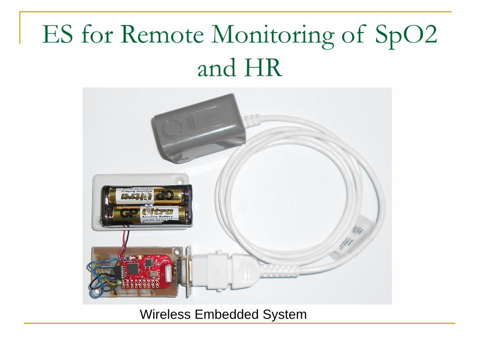
Wireless Embedded System
ES for Remote Monitoring of SpO2
and HR
ES test hardware Test results
ES for Remote Monitoring of SpO2
and HR
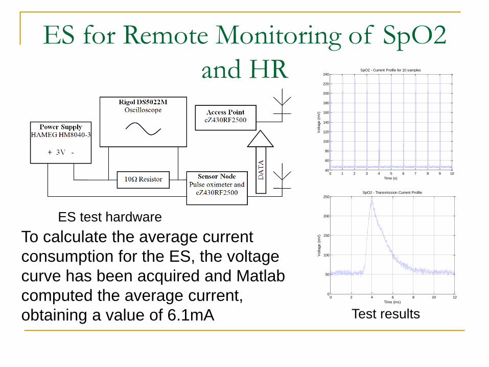
ES test hardware
Test results
0 1 2 3 4 5 6 7 8 9 1040
60
80
100
120
140
160
180
200
220
240
Time (s)
Voltage (
mV
)
SpO2 - Current Profile for 10 samples
0 2 4 6 8 10 120
50
100
150
200
250
Time (ms)
Voltage (
mV
)
SpO2 - Transmission Current Profile
To calculate the average current
consumption for the ES, the voltage
curve has been acquired and Matlab
computed the average current,
obtaining a value of 6.1mA
Conclusions
The described ES allow patients to be monitored:
from a remote location;
preventive or after major medical events;
within their home, as an alternative to medicalsupervision in hospitals.
ReferencesJ. G. Webster, Encyclopedia of Medical Devices and Instrumentation, 2ndEdition, Vol. 1, ISBN:978-0-470-04066-9, pp.471-475, 2006
C. Rotariu, V. Manta, Wireless System for Remote Monitoring of OxygenSaturation and Heart Rate, Proc. of the Federated Conference on ComputerScience and Information Systems, FedCSIS 2012, Wrocław, pp.215-218
C. Rotariu, D. Arotaritei, V. Manta, Wireless System for Remote Monitoring ofAtrial Fibrillation, Proc. of the 5th European DSP Education & ResearchConference EDERC 2012, Amsterdam, 2012, pp.129-133
eZ430RF2500 Development Tool User's Guide, MSP430 WirelessDevelopment Tool, http://www.ti.com/tool/ez430-rf2500
Smiths Medical, Technical Description for Micro Power Oximeter Board,Version 8, 2008.


![홍익대학교 - Hongikibsi.hongik.ac.kr/2021files/200417/20_kor_web.pdf · 공통필수서류+실기동영상 [p.12‘3.공연예술학부필수서류’참고] (04066)서울특별시마포구와우산로94](https://img.pdfslide.net/doc/110x75/5f77d8323b254a170270db09/eoee-eoeeeef-p12a3eeoeeae.jpg)